Richard44
-
Posts
429 -
Joined
-
Last visited
Content Type
Profiles
Forums
Gallery
Events
Everything posted by Richard44
-
For exercise, the 10km limit doesn't apply - you can go anywhere within your local LGA (I checked with Services NSW). The 10km limit applies to shopping. Hobby Tools Australia has a good selection and I've had good service from them. Cheers Edit. I wasn't quite right above - shopping is allowed anywhere in your LGA. "...can only shop, exercise or engage in outdoor recreation within their local government area (LGA) or, if outside your LGA, within 5 kilometres of your home."
-
 We've got some weird creatures here in Oz, but barking fish?? 😆 (Yes, I know Barking is a town in England, but temptation got the better of me.)
 -
And another welcome, not from Sydney, but from Gosford. We're in lockdown, not full lockdown, so I can actually get out for exercise in my local area - so far. But Covid cases are increasing.....
-
Chris, Your output is absolutely amazing!!! Just when do you sleep???? Cheers
-
When I was a kid, we used to make cannons out of empty .303 cartridges, drill a hole in the end, put in gunpowder from a firecracker plus a wick add a ball bearing, light the wick and let it rip!!! Could we do this with the Sphinx cannons? 😆
-
Hi B.E., Like you, age (I'm 77) and space have had me thinking about what to build, if anything, after I finish Pegasus. Chris's Sphinx has slowly but surely risen to the top of the list. And like you, I would build it without masting. It's too soon now to order one, not that there are any left, but sometime. Thanks Chris and James. Cheers
-
That's looking good Tim. And congratulations on your engagement.
- 164 replies
-
- 1
-

-
- fly
- Victory Models
- (and 4 more)
-
Glue up two pieces of scrap with your PVA, let dry, and try the mineral spirits on it. I don't think there will be any effect, after all, the stain you have applied is oil/mineral spirit based.
-
I'm following your build with interest Ron, as it's a kit I may buy myself at some time.
-
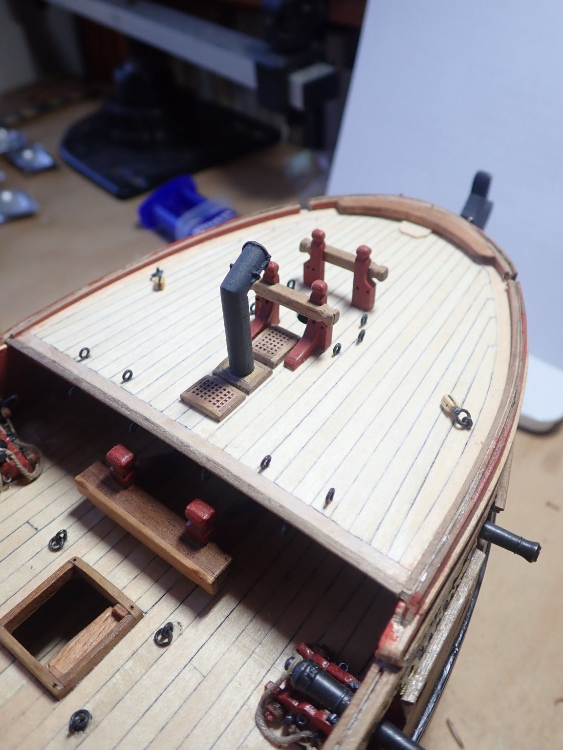
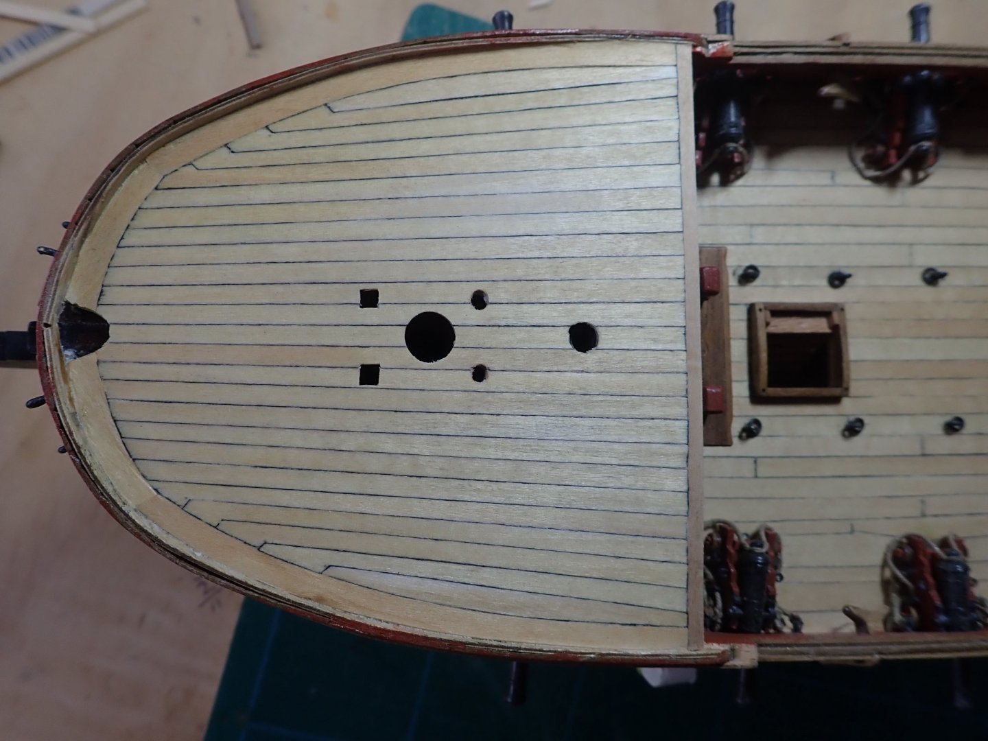
Thanks for the likes. A very brief update of work done on the foredeck. A breasthook and a partner for the bowsprit were added. The topsail sheet pins were inserted through the deck and the bitt attached. I had shortened the pins of the jeer standard because of the stove beneath and glued a block beneath the deck, prior to fitting it, to take the pins. The jeer standard with the short pins was then glued in place and its bitt attached. Small cheek pieces had been fastened to the outside of all four pins and holes drilled to simulate sheaves. Coamings for the chimney and the two steam gratings that sit above the stove were made. Instead of the gratings supplied in the kit, I bought a grating that was of a much finer mesh and used this. Cheers

- 104 replies
-
- 7
-

-
- pegasus
- victory models
- (and 2 more)
-
Absolutely marvellous BE. Congratulations, and like others, I'm looking forward to your next build 👍. Cheers
- 185 replies
-
- 3
-
-
- queen anne barge
- Syren Ship Model Company
- (and 1 more)
-
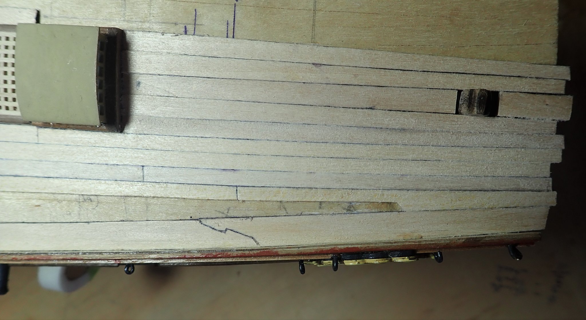
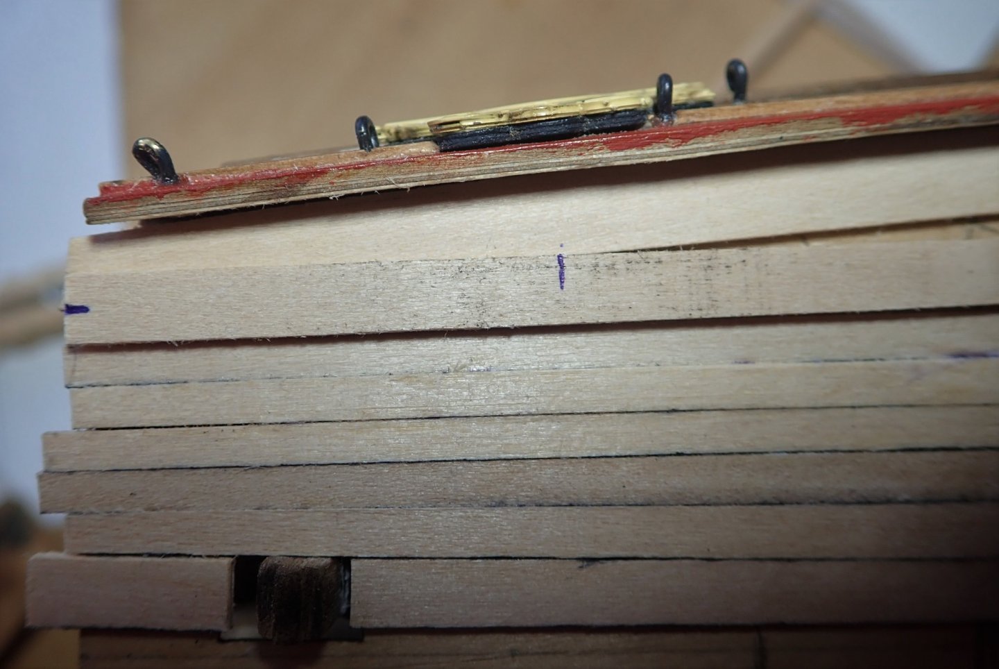
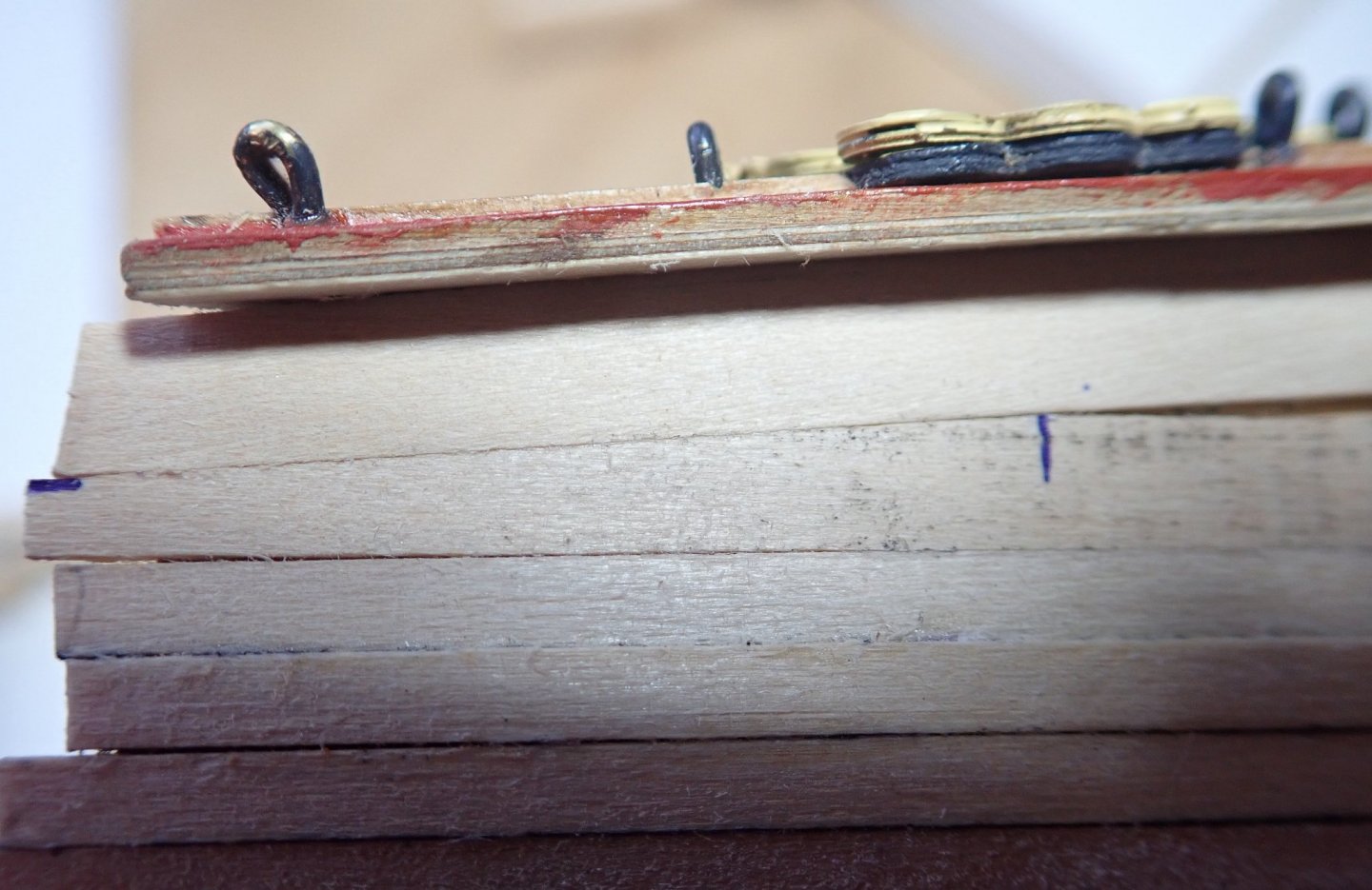
Thanks for the likes. The planking of the quarterdeck was completed. I made one mistake - one of the hooded ends abuts the hooked scarph in the margin plank, and it shouldn’t 😖. I did think about tearing up the planking and starting again, but decided against it. Not a big deal as it’s not going to affect the build, and I can always dump a coil of rope over it later 😁. The foredeck was then planked. Again, tapered planks, hooded ends and no joggling. The TFFM plan shows the margin plank as one continuous piece. I made this in two pieces simply to keep the grain running roughly along the length of each piece to avoid splitting. The two pieces were just butt joined and the join was located where the cathead will be and thus hide it. I did think about using the technique for tapering planks that Jason (Beef Wellington) described in his build log of HMS Jason, (link here) but I used a sharp knife and a straight edge instead. That’s it for the moment. Cheers
- 104 replies
-
- 5
-
-
- pegasus
- victory models
- (and 2 more)
-
Thanks for the comment Jason, much appreciated.
-
Ah...., I actually don't know what book 😚. I have the original 12 part Practicum and I have no idea how this relates to the books, but one of the authors, Greg Herbert, is a member here (dvm27) and you could ask him via a pm.
- 104 replies
-
- 1
-
-
- pegasus
- victory models
- (and 2 more)
-
Thanks for the comment. The plan I'm using as a guide comes from the books The Fully Framed Model by David Antscherl & Greg Herbert, a very complete description of Swan-class sloops. The books are available from Seawatch Books (seawatchbooks.com). Cheers
- 104 replies
-
- 1
-
-
- pegasus
- victory models
- (and 2 more)
-
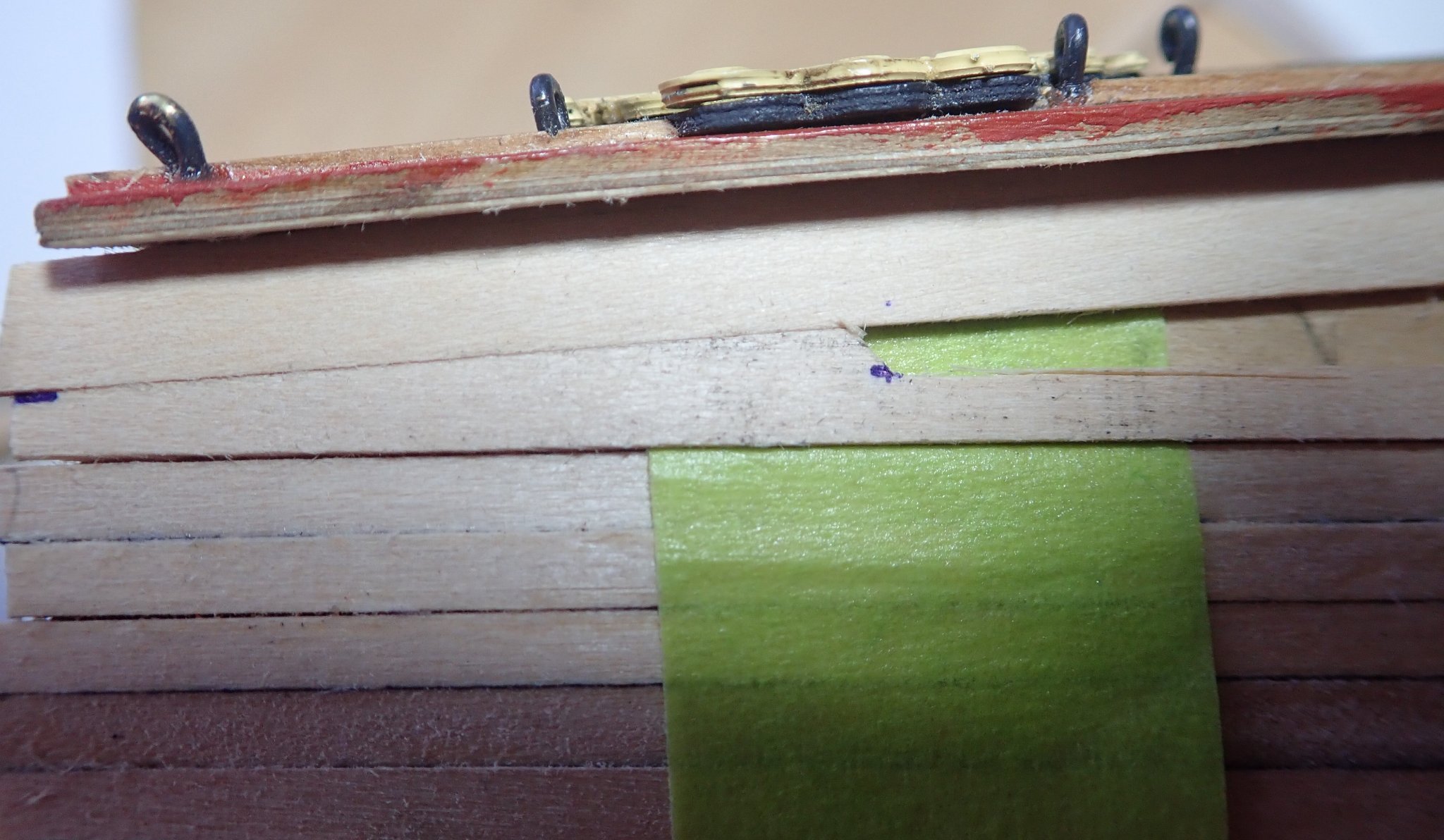
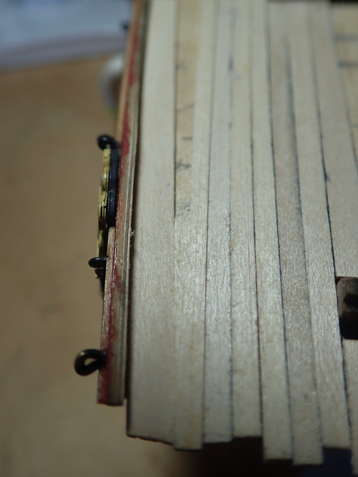
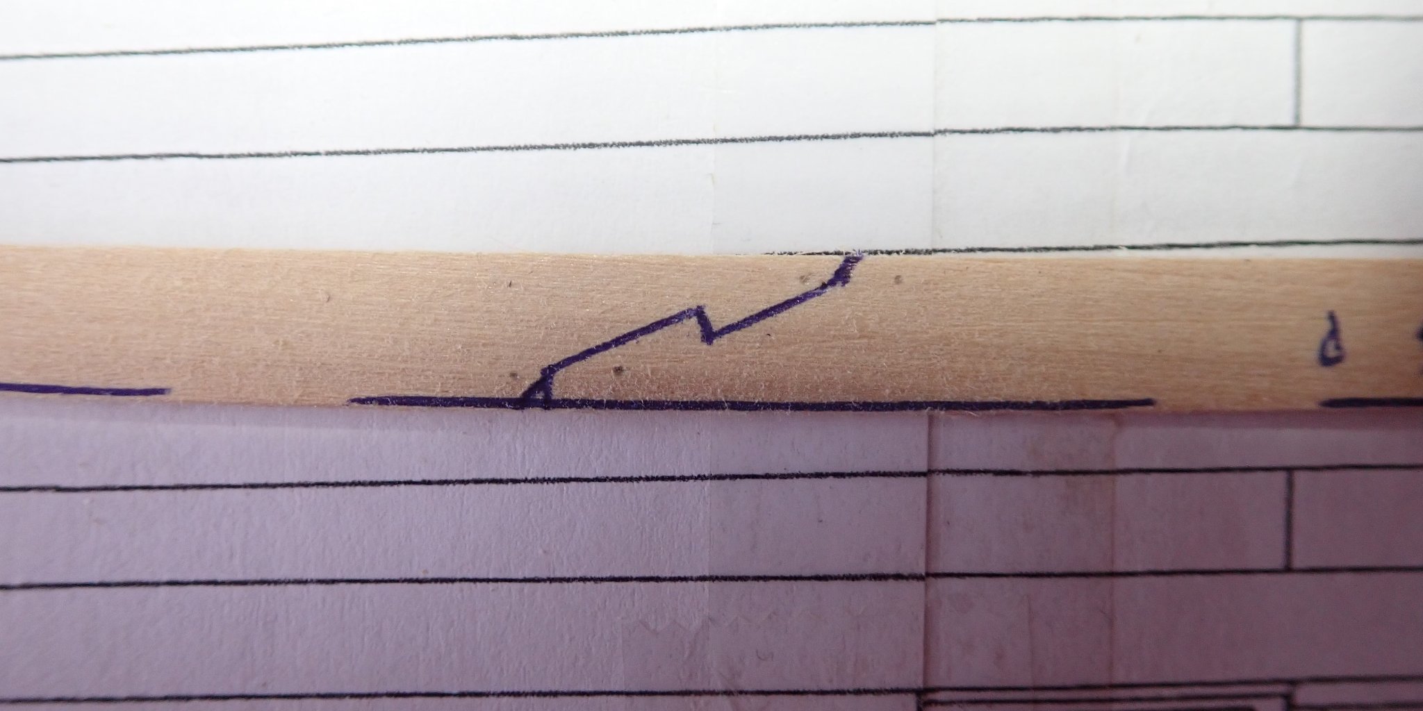
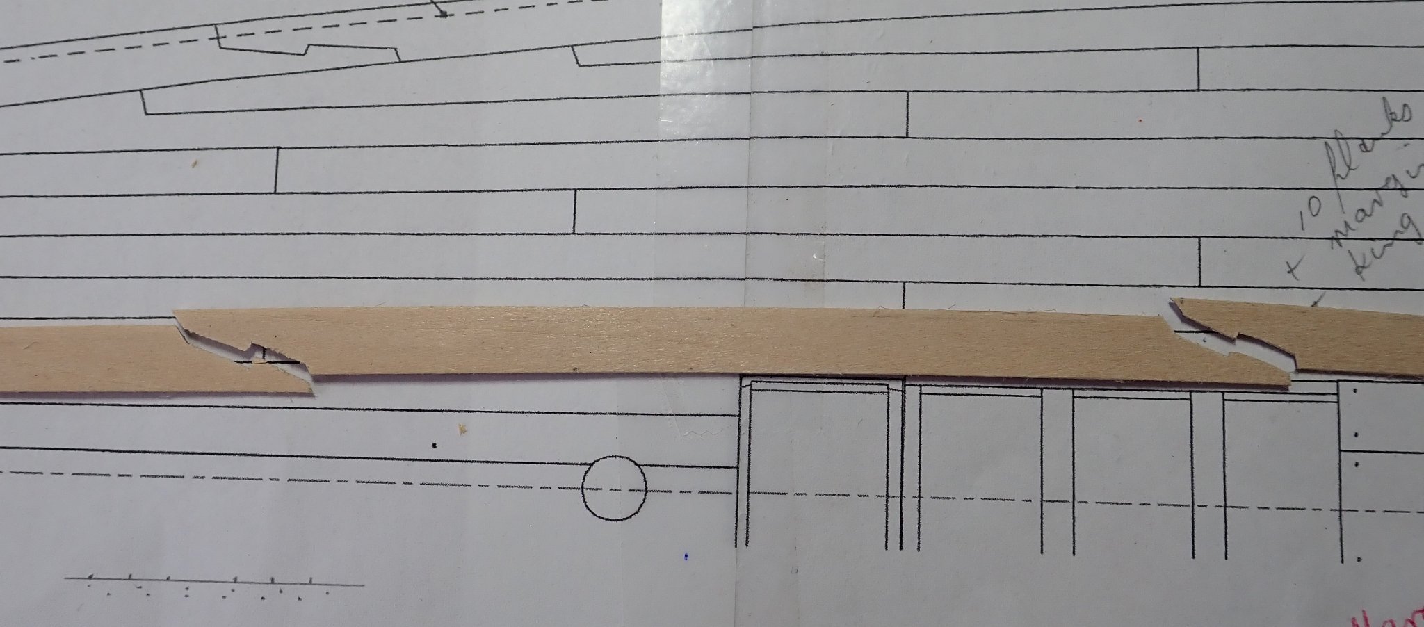
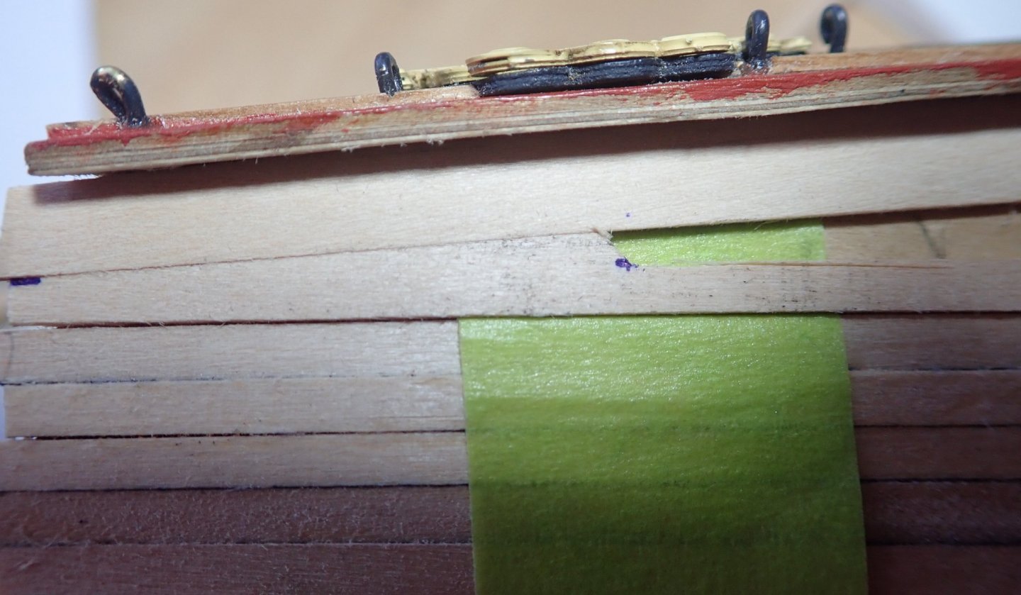
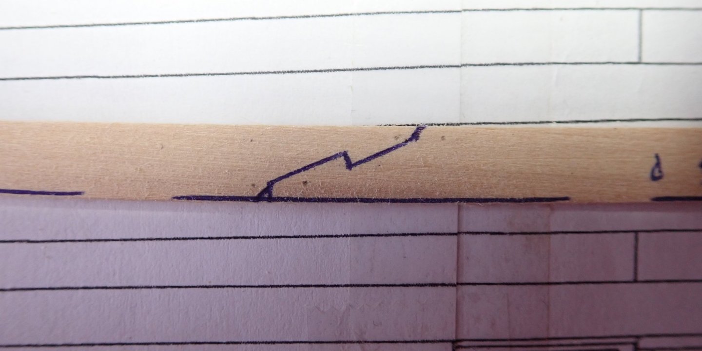
I’ve started to plank the quarterdeck. All the planks, except the king plank, are tapered. None of the planks is joggled into the margin plank but but some have hooded ends. The plank pattern is based on that given in TFFM. The first few planks in place. I decided to cover the two scuttles at the forward edge of the deck with solid covers rather than gratings as suggested in the instructions. My reasoning was that gratings provide light and ventilation through the deck and as these scuttles are very close to the forward edge of the deck, gratings here will do little, if anything, to provide additional light and air down to the upper deck. The next photos show how I marked and cut the hooded ends of the two planks that needed these. The piece of strip wood in the photos was a demo only, and not the actual plank. The margin plank (cut from some sheet) was held in place and the strip offered up. The width at the end was marked (A), and the point where the width of the strip became less than the gap between the margin plank and the already installed plank was marked (B). The strip was trimmed to these two points. At B, the plank was marked with a point 2mm in from the outer edge, the plank here was 5mm wide. An angled cut was made and the plank was tapered from here forwards, as shown in the photo. The actual plank is shown trial fitted. The margin plank has two hooked scarph joints. The underside of the margin plank with one of the scarph joints marked out with a pen. A sharp knife was used to cut the plank into three sections. The margin plank glued in place. Cheers


- 104 replies
-
- 6
-
-
- pegasus
- victory models
- (and 2 more)
-
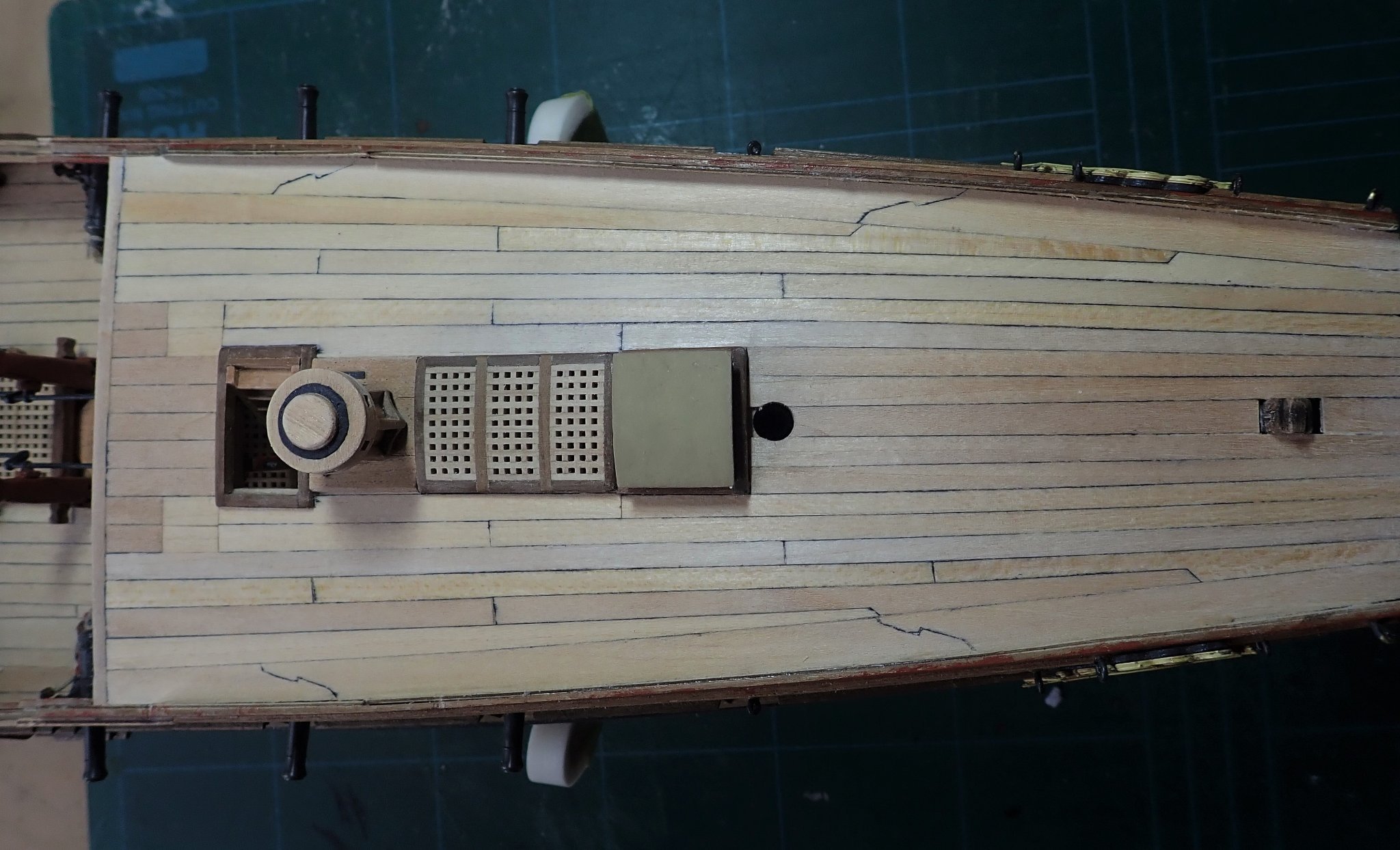
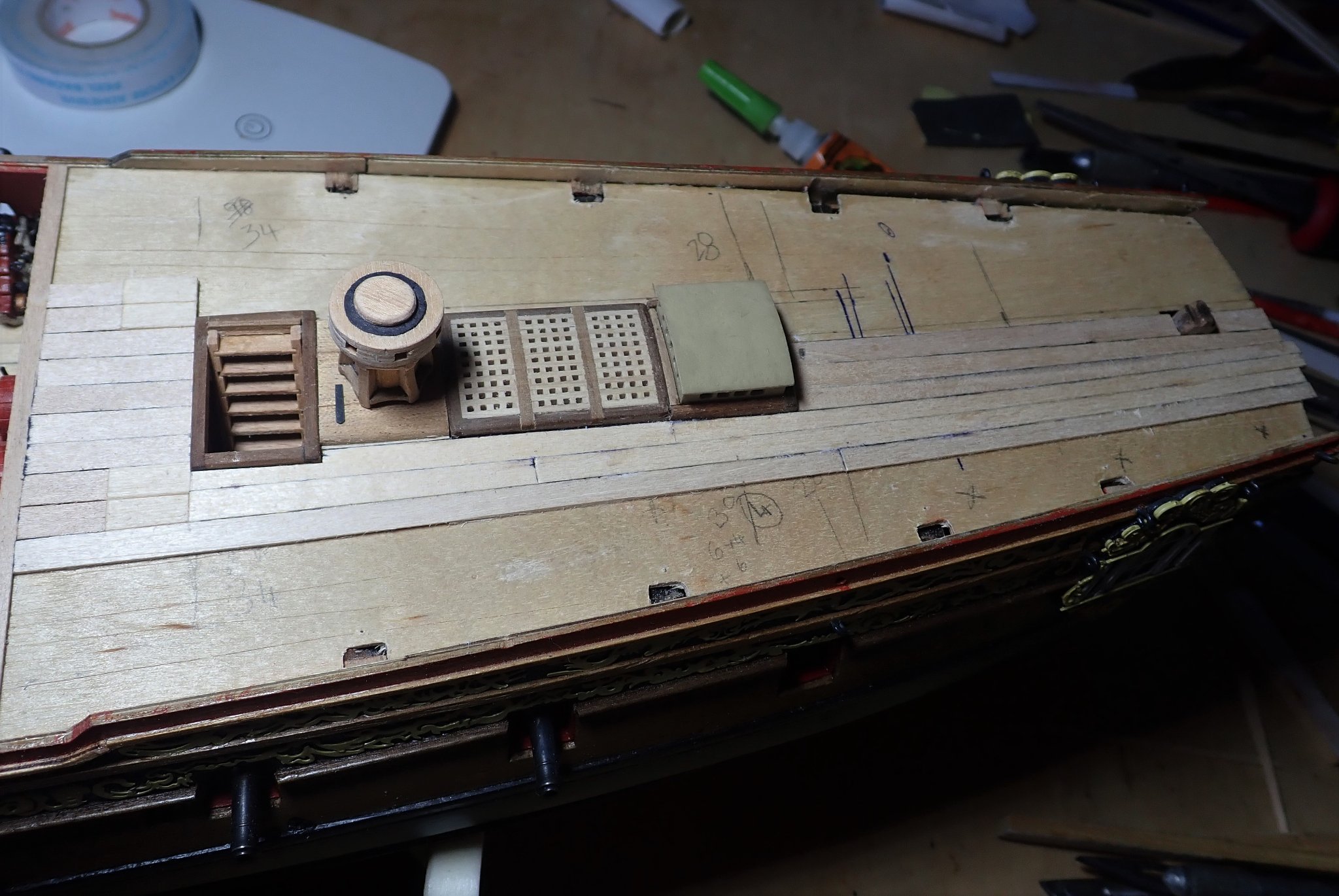
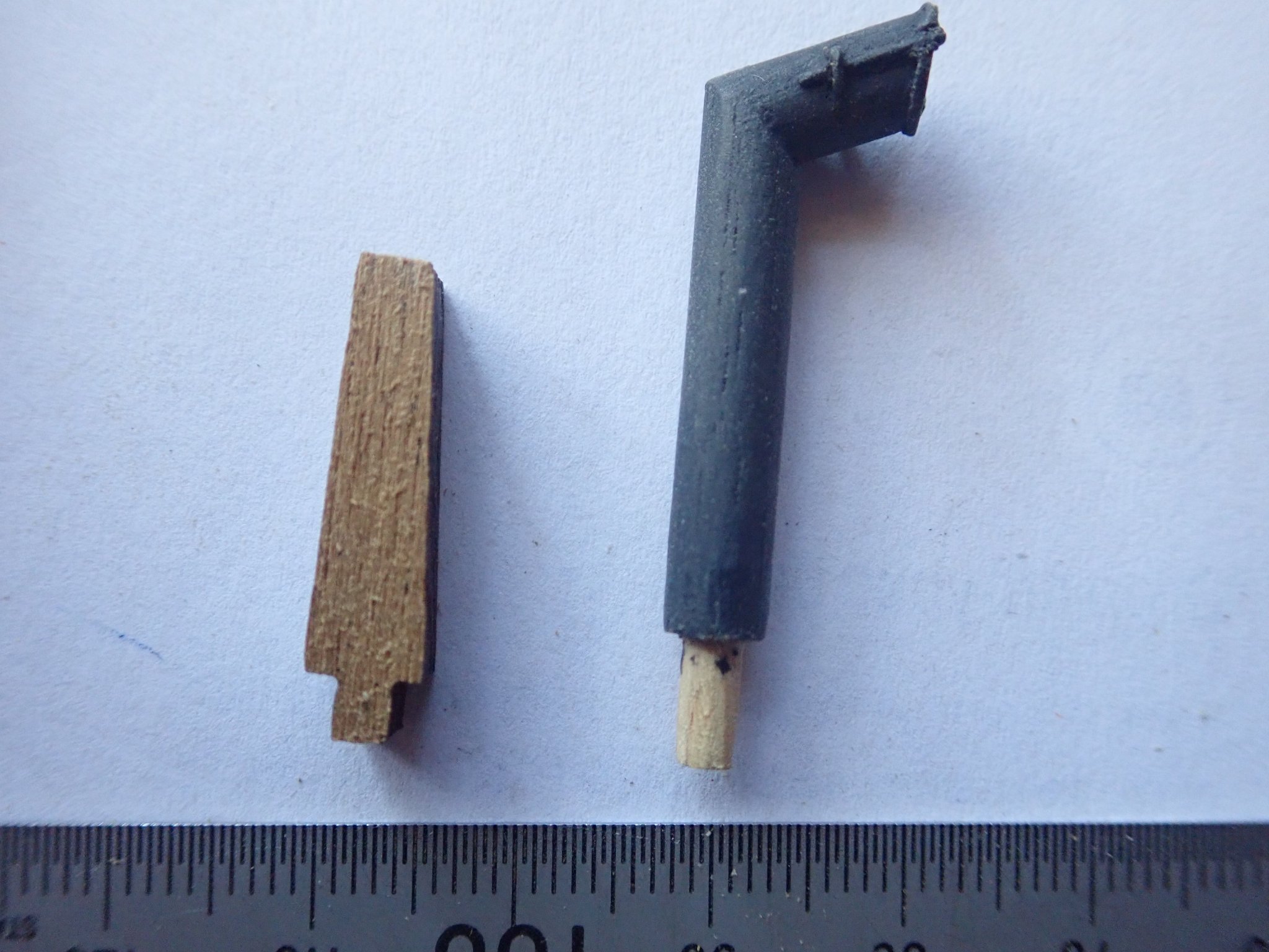
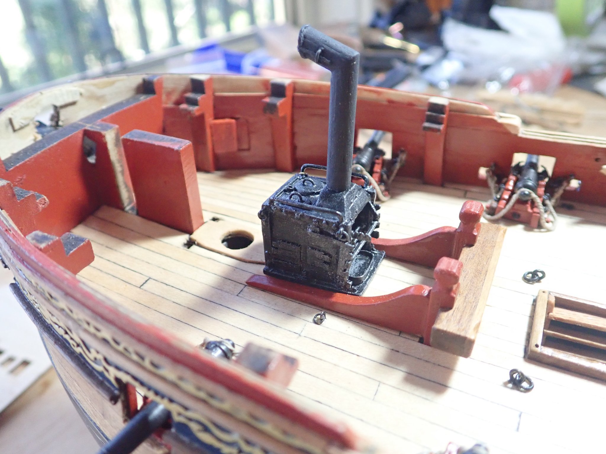
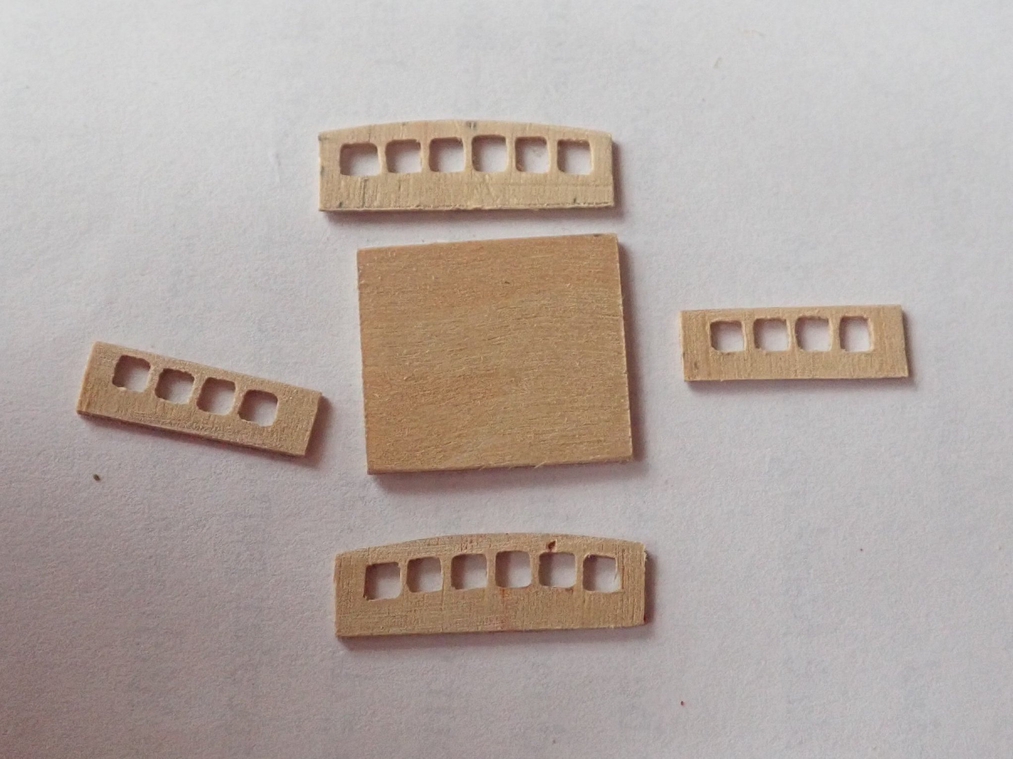
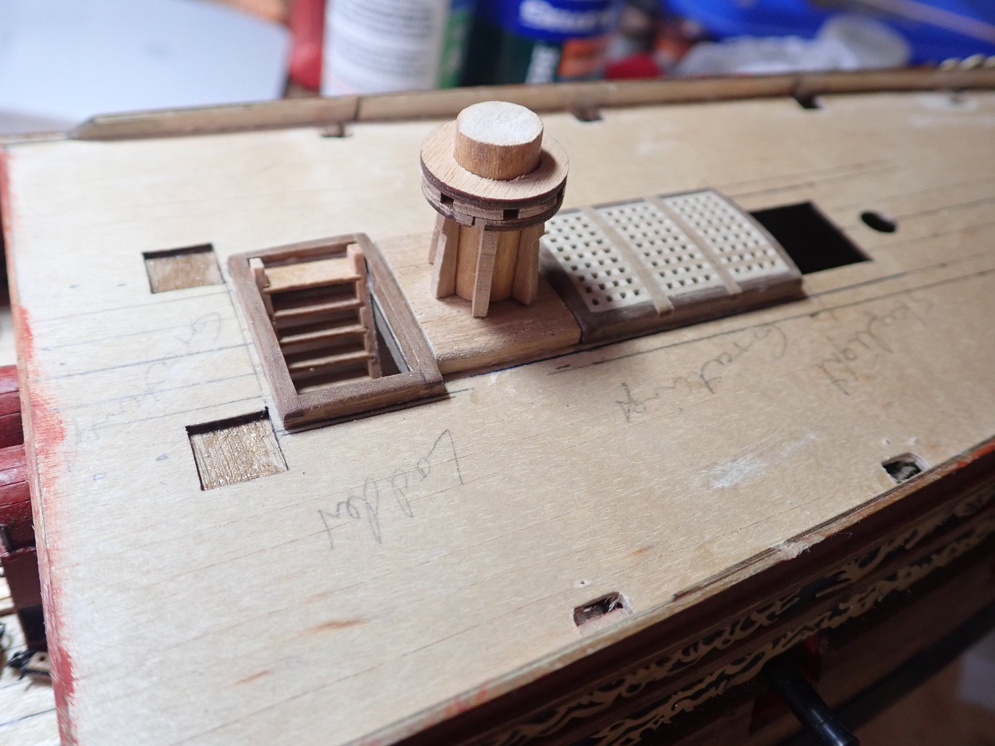
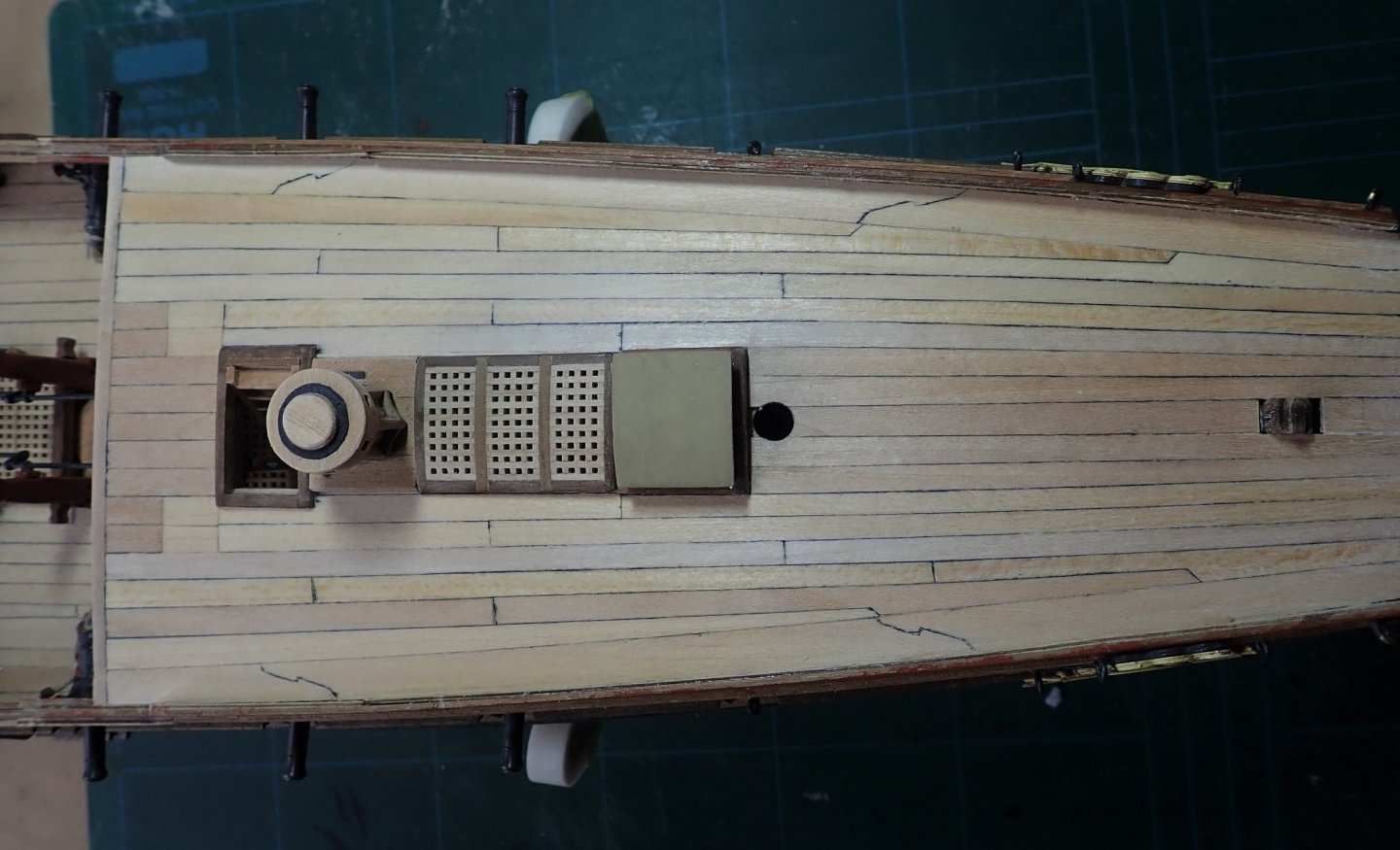
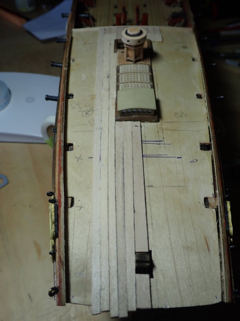
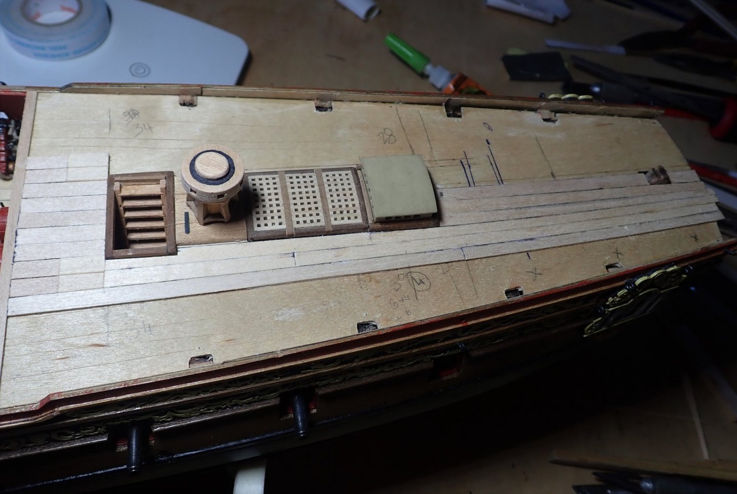
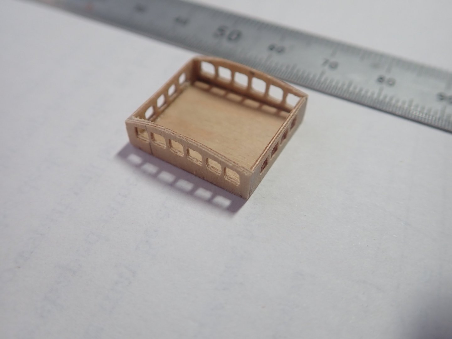
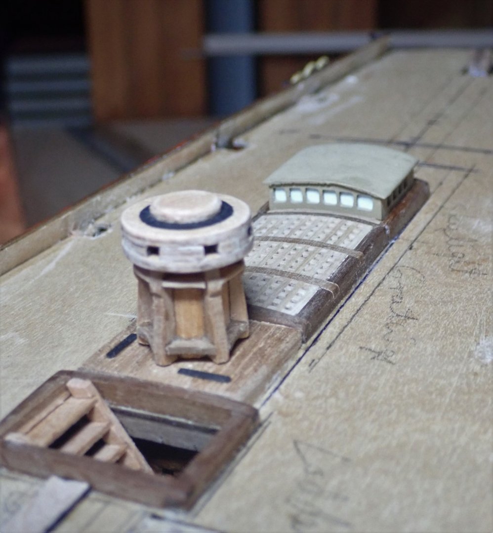
The stove needed a chimney. The one supplied with the kit looked a bit ordinary, so a new one was made. A wooden dowel was used, cut at an angle and the two parts rejoined. The baffle plate is a section cut from the handle of a very cheap paintbrush, it just happened to be the right diameter, and the slides for it are brass wire. This photo shows the kit supplied one and the new one. The stove and its chimney. The false fore and quarter decks were next fixed in place. The two breast beams were thinned and their undersides curved to improve their appearance. The ladder, gratings and the capstan were added to the quarterdeck. The capstan was made using the same technique I described in Post 27 for the one on the upper deck. The kit provides a skylight (the companion top) to go just aft of the gratings, but Antscherl in TFFM suggests that this was unlikely and that a clerestory cover over the hatch was more likely. So I built one using the diagram in TFFM as a guide. Good quality 1mm ply was used, the four sides were cut out, and a series of holes drilled. These holes were then opened out using square and triangular section needle files. The ply had been oriented so that the face grain ran parallel to the window frames, and splintering was thus avoided. “Glazing” was added with gloss blue photo paper as I did for the quarterlights. The four sides and base, and glued together. The finished companion top in place. The corner of the roof looks odd, but it’s the camera angle. Cheers


- 104 replies
-
- 5
-
-
- pegasus
- victory models
- (and 2 more)
-
Keep at it Mike. Things do improve once the second layer goes on. From memory, the limewood strips are narrower than those of the first layer, so the second layer strips will overlap the seams of the first layer and impart considerable strength and rigidity to the hull (you've probably realised this already). I found the build quite frustrating at times, but the finished model looks really good. Cheers
- 62 replies
-
- 1
-
-
- lancia armata
- panart
- (and 1 more)
-
You're welcome.
-
Hi Starlight, Yes, I would have planked the inner bulwarks first. Then I drilled the holes for the cannon eyebolts from the outside and through the inner bulwark. Then finished the second planking. By doing it this way, I avoided the hassle of trying to drill the holes from the inside with the drill (pinvice, whatever) just above the deck, and in particular, not drilling all the way through the second planking. From the outside, before the second planking, the drill hole can go all the way through; from the inside, after the second planking, the drill hole has to stop short - this can be tricky. Hope this makes sense. Cheers
- 104 replies
-
- 2
-
-
-
- pegasus
- victory models
- (and 2 more)
-
Hi Mike, I'm enjoying Pegasus. It's a good kit and there are plenty of build logs to read for advice at different times of the build. I have done quite a few modifications, using Antscherl & Herbert's treatise, The Fully Framed Model as a guide. Amati's instructions could have been better, but they're brilliant compared to Panart's for the launch. Later in your build, you will find that some of the instructions are not in a logical order, and the plans are often confusing. Still, once finished, it makes into a nice model. Cheers
-
I'm following your build 🙂. Can't really offer any advice at the moment as I planked my launch years ago - and there is no chance that I can remember what I did back then 😁.
-
Thanks B.E., much appreciated.
-
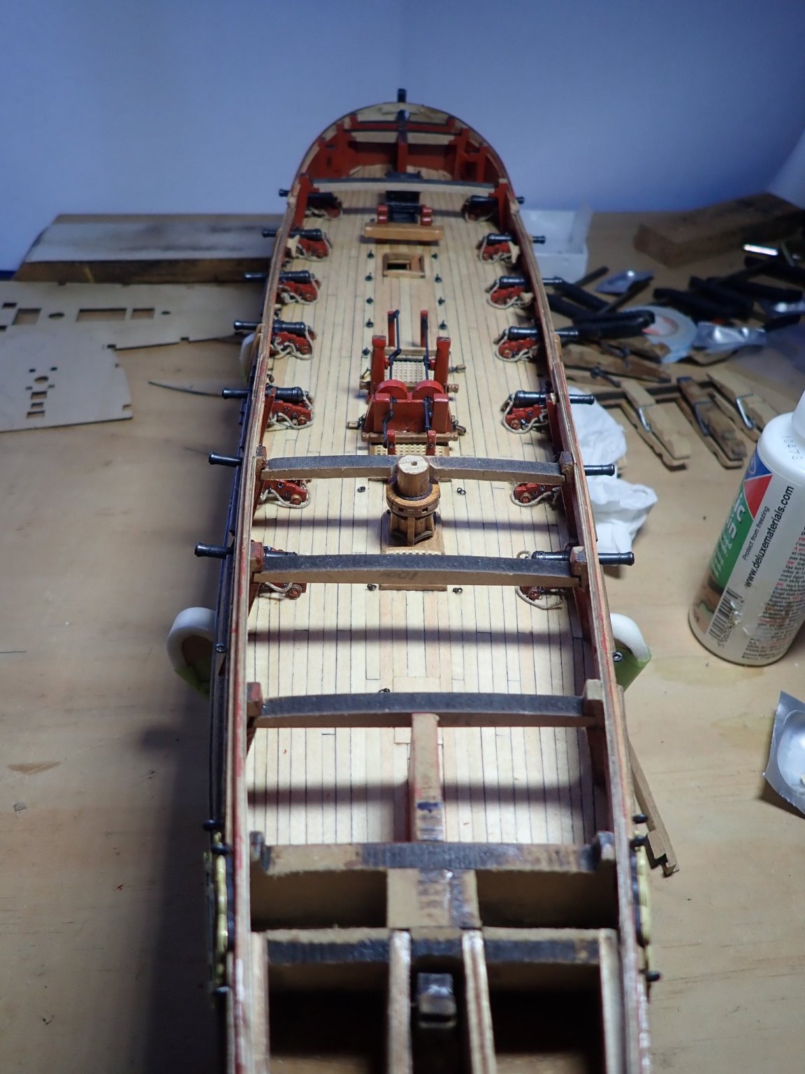
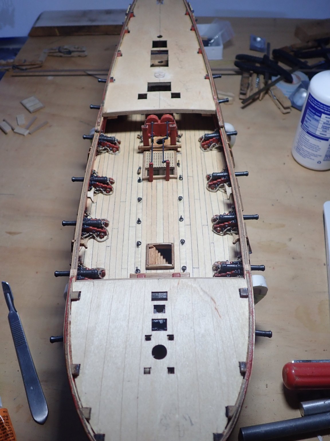
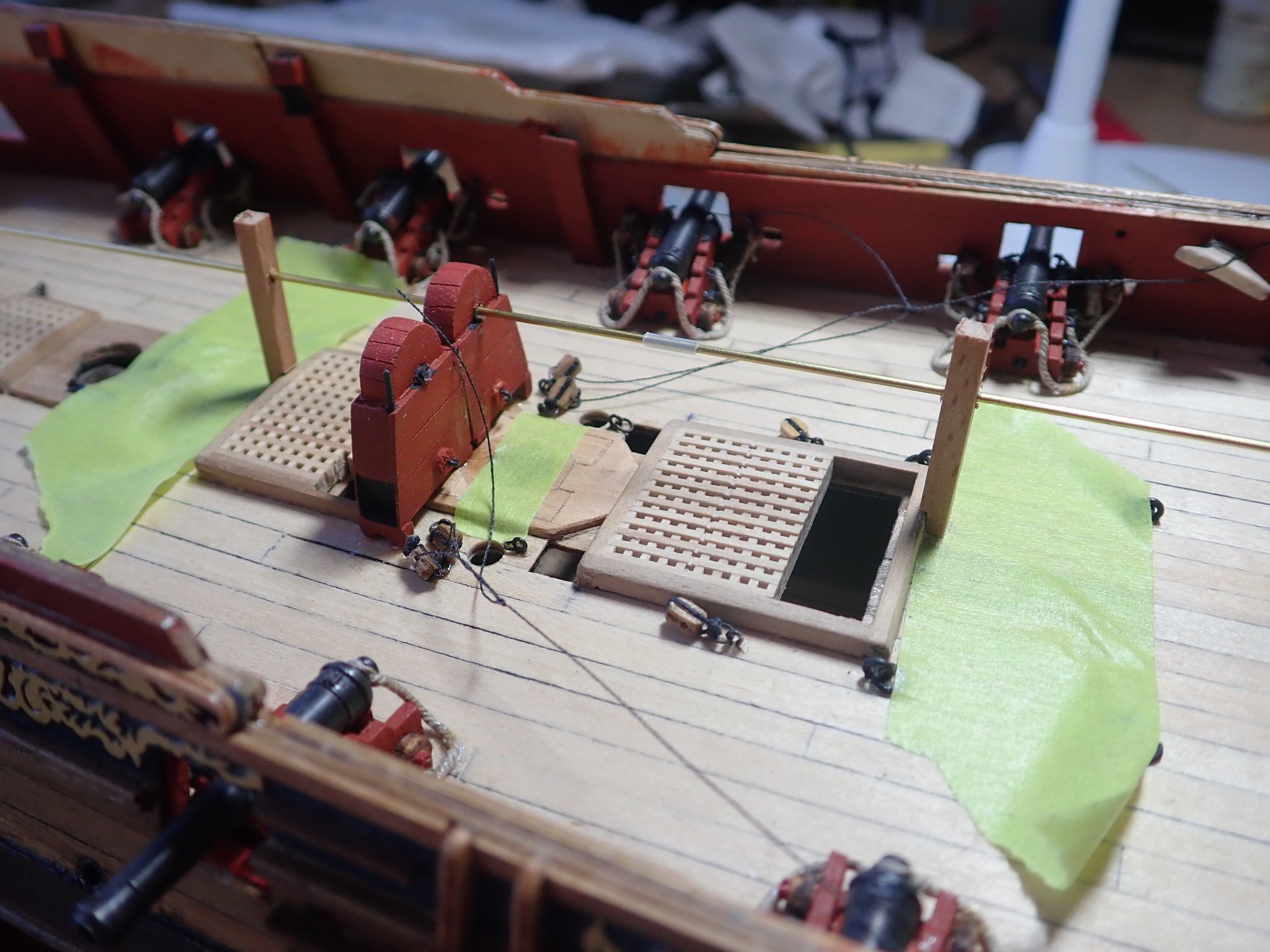
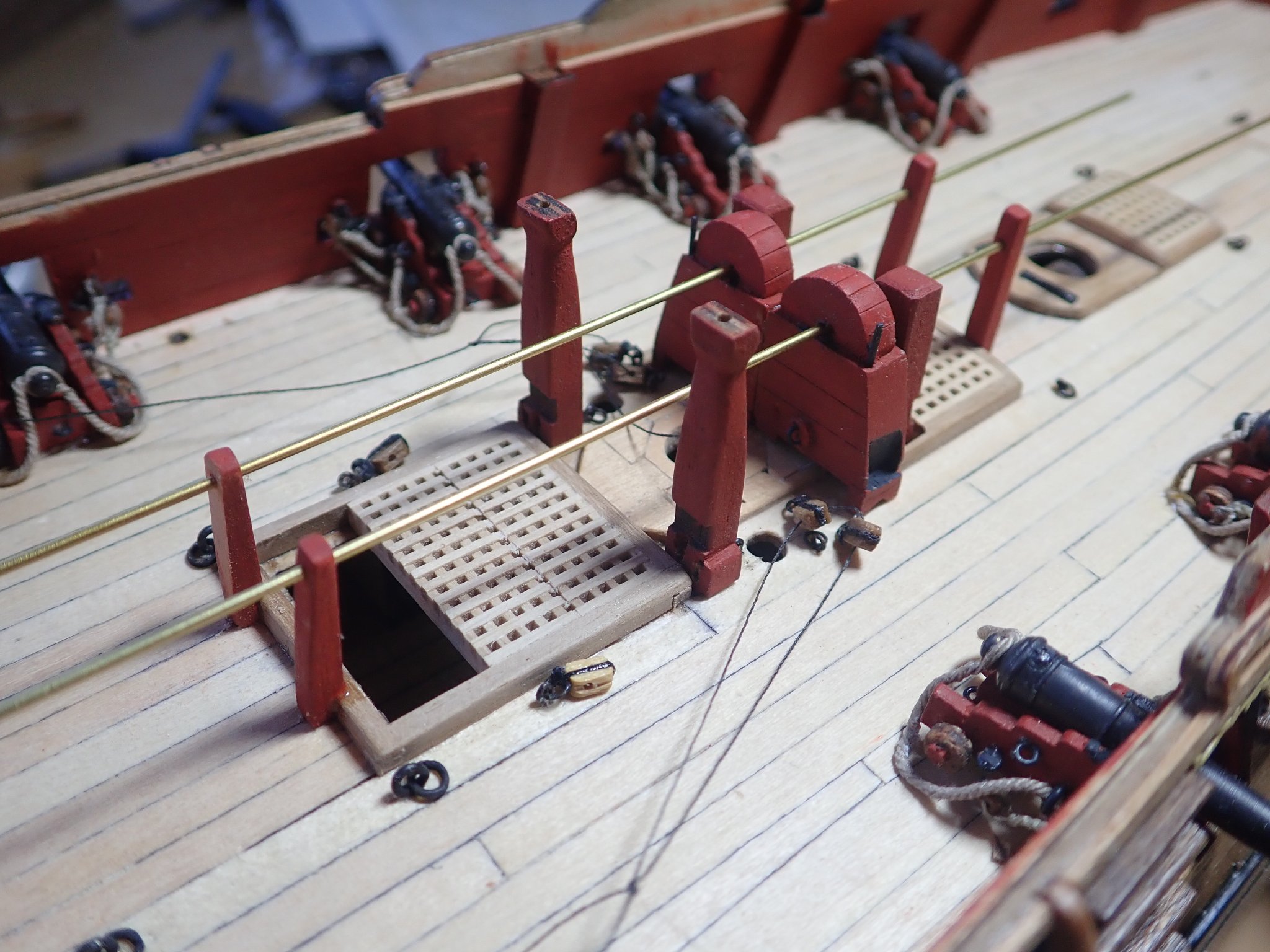
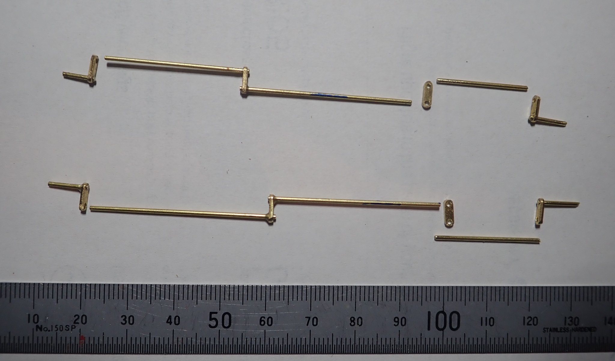
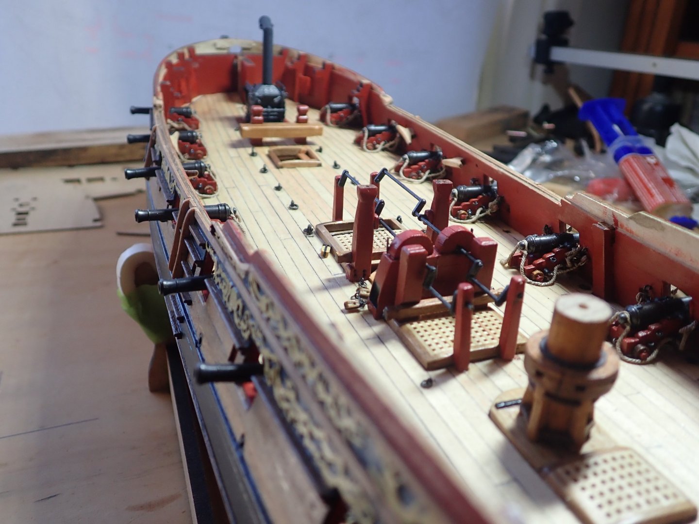
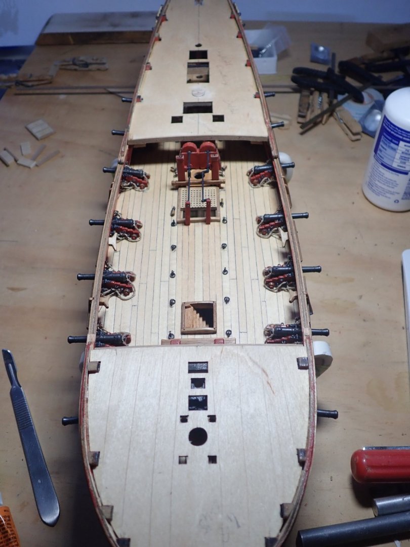
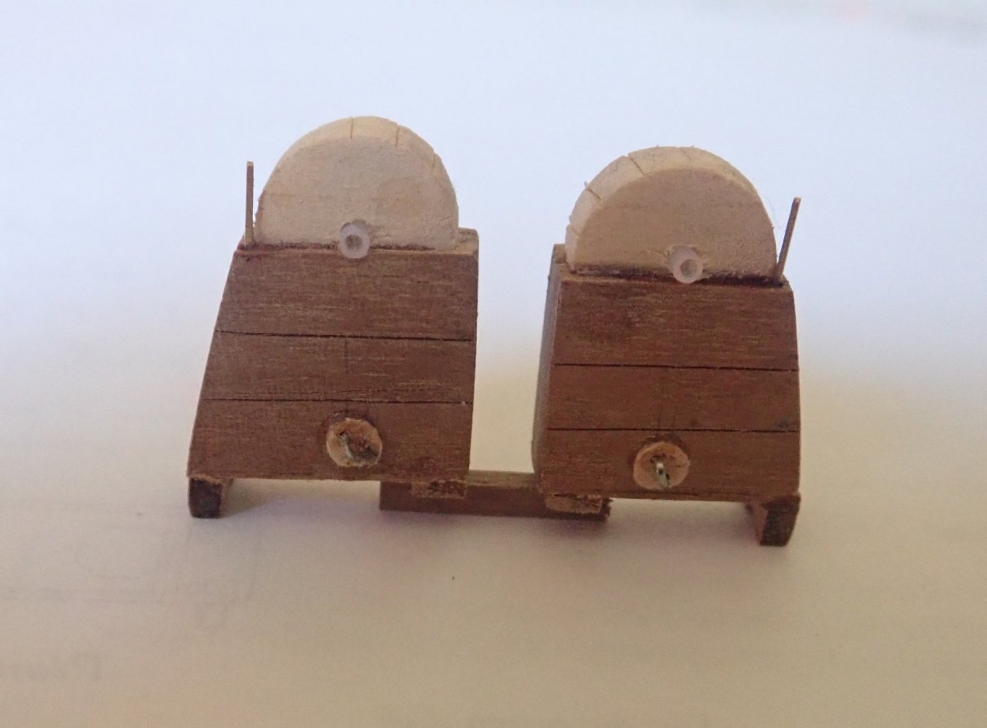
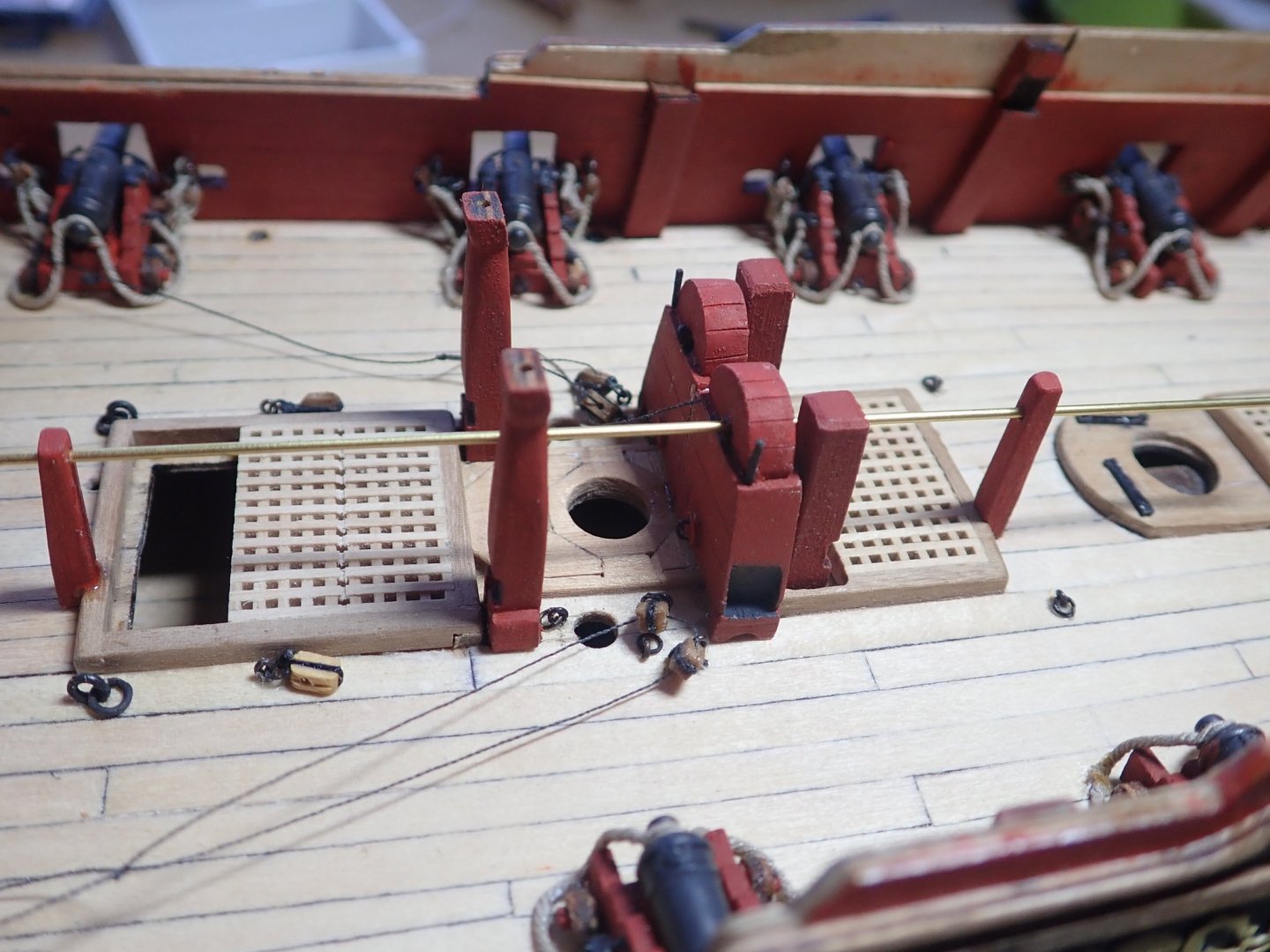
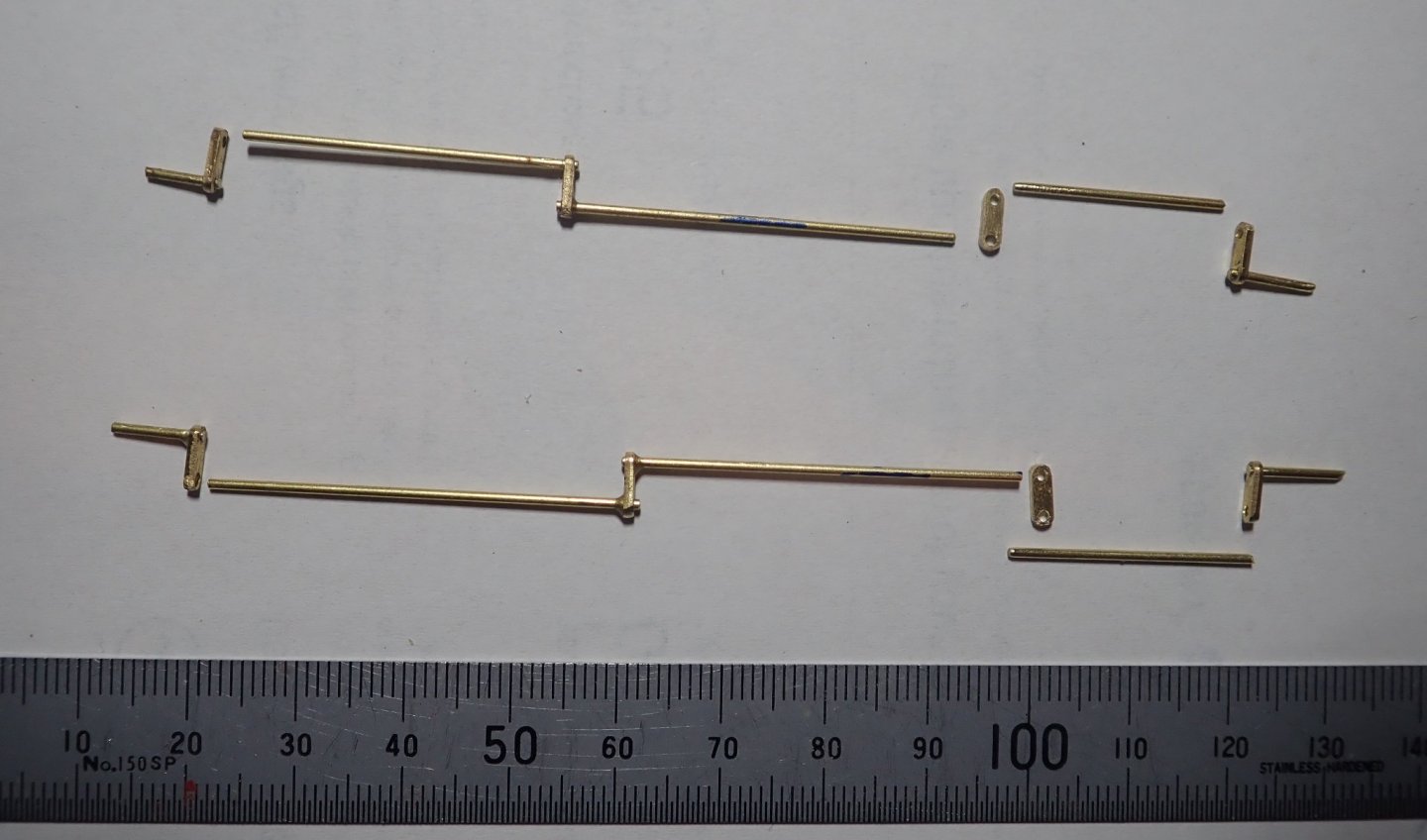
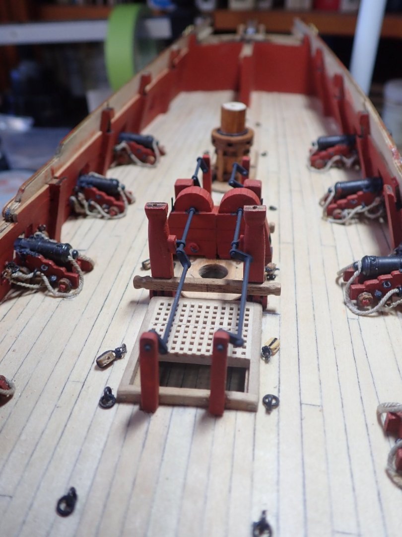
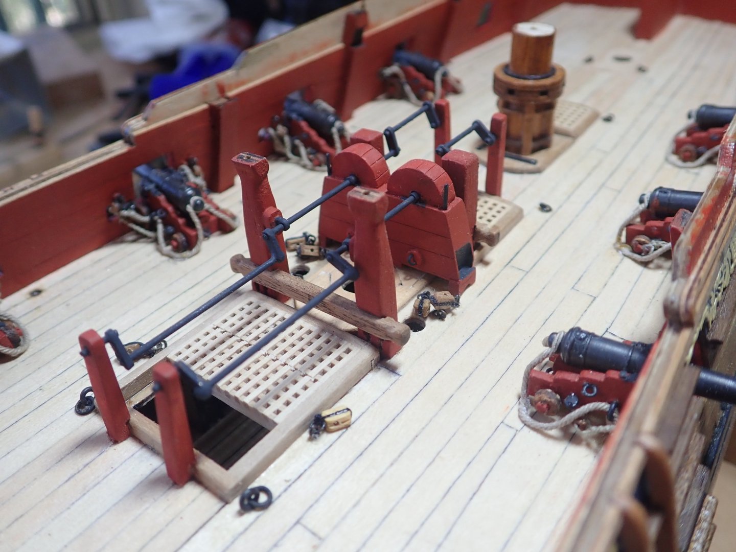
Thanks for all the likes. The chain pumps were the next task. I assembled the two-piece pumps as supplied, put them on the deck and immediately realised there was a significant problem. Specifically, the axletree was too close to the deck, so close in fact that the winches may not have had clearance over the grating over the hatch. It would have been very difficult, to say the least, for the crew to operate the winches. I measured the height of the axletree from the deck on the kit plans and it was 9mm, compared to 17mm for the same measurement on the NMM plan. So what to do. Kit bash of course, and this was going to include the aft winch which is not shown on the kit plans. The jeer bitt was also going to be moved from the front of the pins to the rear, as on the NMM plan. I tried to modify one of the already assembled pumps, but stuffed this up, so decided to scratch build two new ones. These were based on drawings in TFFM. The two new pumps with some embellishments compared to the kit versions. Scoring was used to simulate individual planks. The pumps in place with wooden pillars at each end to support the winches. These were notched to fit onto the hatch coamings, and the ends rounded to fit into holes drilled through the deck. A length of brass rod was used to align the pillars and the pump. The pillars shaped and painted. Port and starboard done. The axletrees and winches were made primarily of 1mm brass rod, while the actual cranks were made from some brass fittings left over from a previous kit. They just happened to be the right size after being trimmed to length. Left over brass fittings (plus wood spacers) were also used for the rhodings (bearings) that are on the pins of the main topsail sheet bitt. Epoxy was used to join the pieces, as final assembly was going to be on the deck. The various parts ready for final assembly. All complete, and yes, for those who are wondering, the winches do actually rotate.😊 Cheers.


- 104 replies
-
- 12
-
-
- pegasus
- victory models
- (and 2 more)