HOLIDAY DONATION DRIVE - SUPPORT MSW - DO YOUR PART TO KEEP THIS GREAT FORUM GOING!
×


Richard44
-
Posts
429 -
Joined
-
Last visited
Content Type
Profiles
Forums
Gallery
Events
Everything posted by Richard44
-
 Thanks Chris. I had assumed that this was what you did. Very neatly done.
 -
Absolutely outstanding Chris. Are the control cables to the elevators and rudder made from EZ-Line? You mentioned in an earlier post that this stuff could be difficult to glue. Cheers.
- 98 replies
-
- 12
-

-
Keep at it Mike, you're nearly at the fun stuff. 😁
-
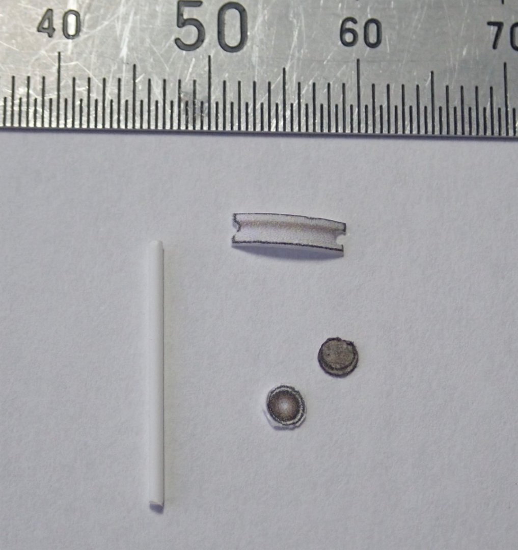
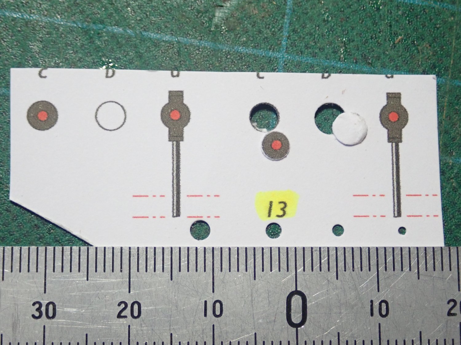
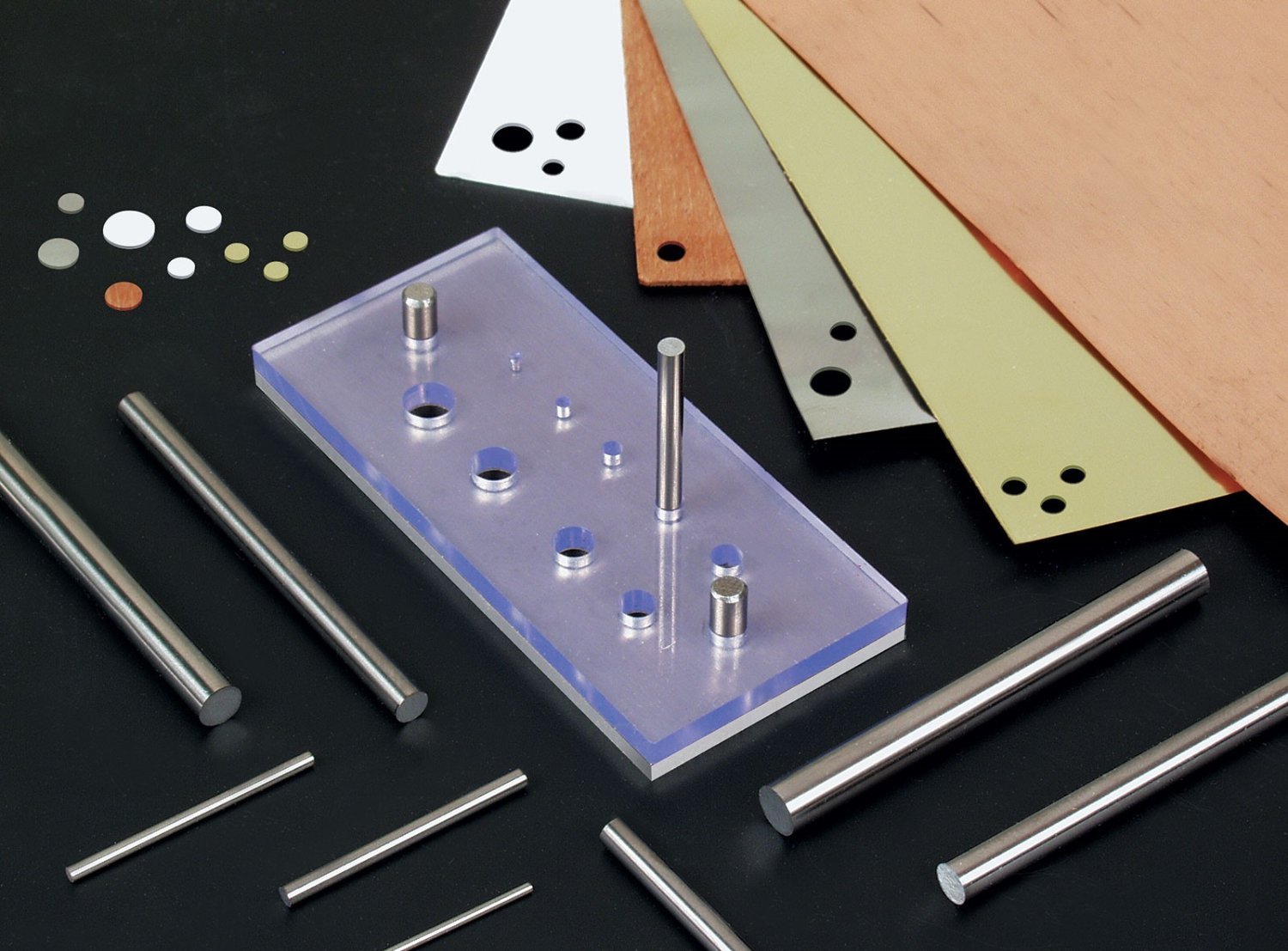
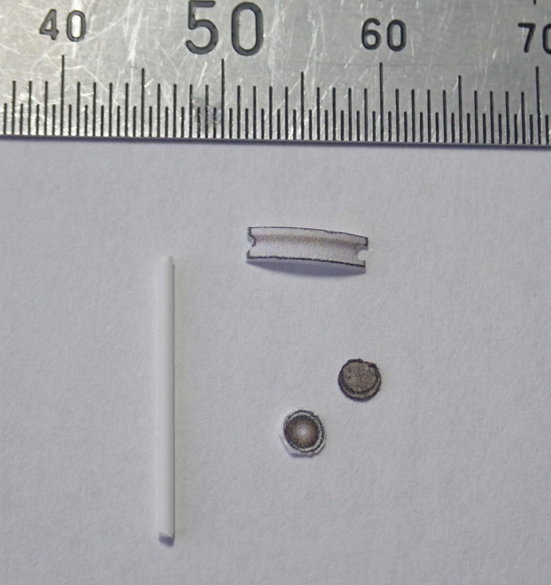
Thanks for all the comments and likes. One tool that I found to be very useful was a set of Micro Mark micro punches https://www.micromark.com/Micro-Punch-Set. (I bought mine from Hobby Tools Australia). These were good for punching small holes or for punching out discs instead of trying to cut them. The photo shows a couple of discs punched out of one of the printed sheets from Christiaan Brunings. I found that sometimes thin CA dripped onto the back of the proposed disc before punching out made for a cleaner cut. Cheers

- 23 replies
-
- 6
-

-
-
- card
- World of Paperships
- (and 2 more)
-
Thanks for the praise B.E.. Funny you should ask about a waterline setting. World of Paperships actually has a free download of a jetty that CB could be moored to. I've got the file and will make it up in a day or so. I'm intermittently following your build of Sphinx and continue to admire your skills 🙂. Cheers
- 23 replies
-
- 1
-
-
- card
- World of Paperships
- (and 2 more)
-
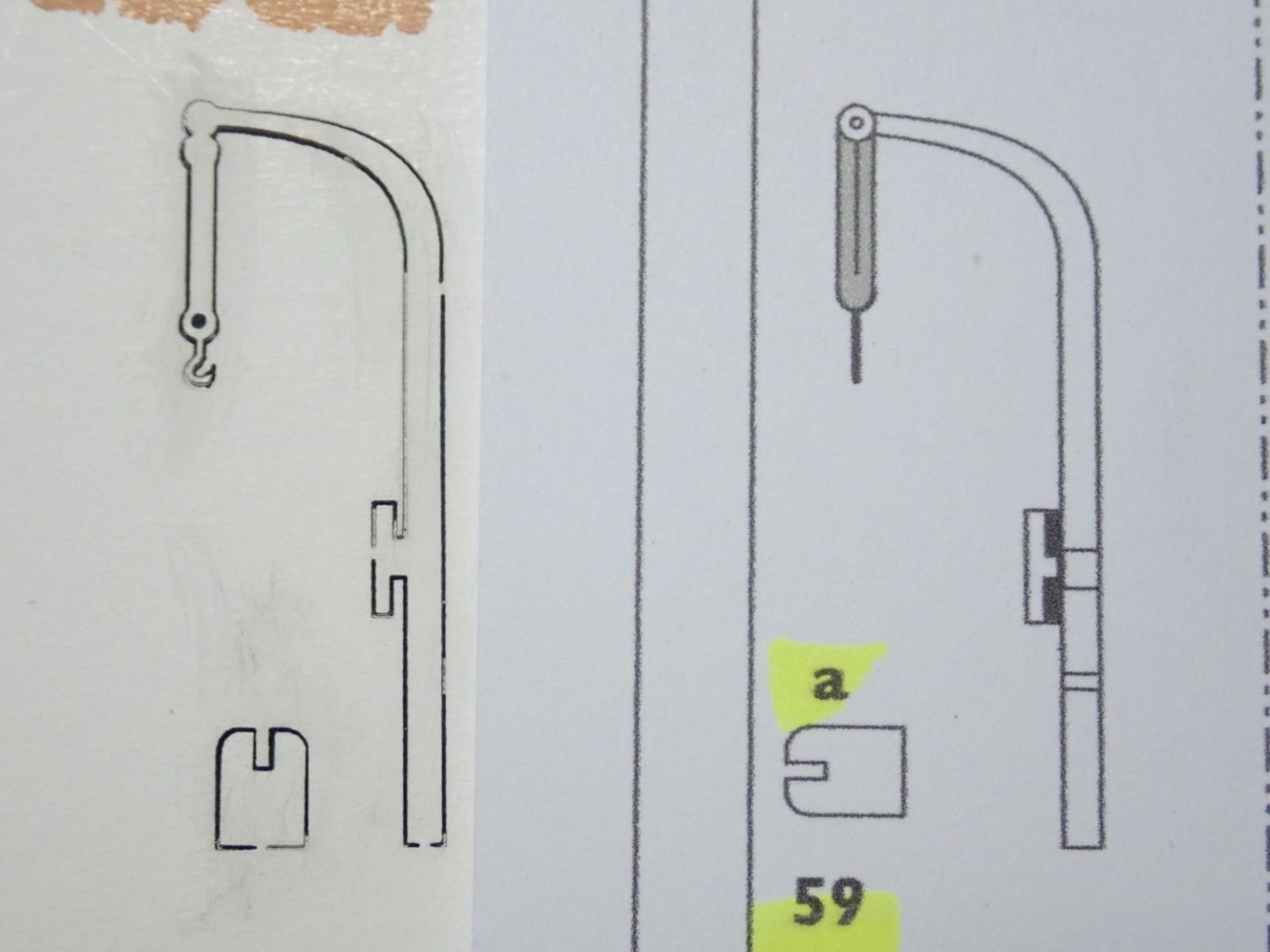
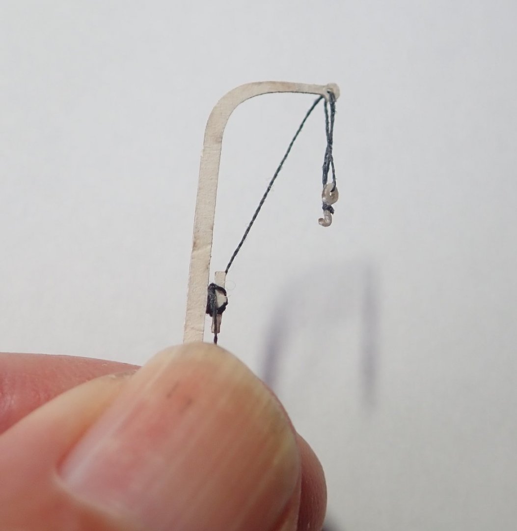
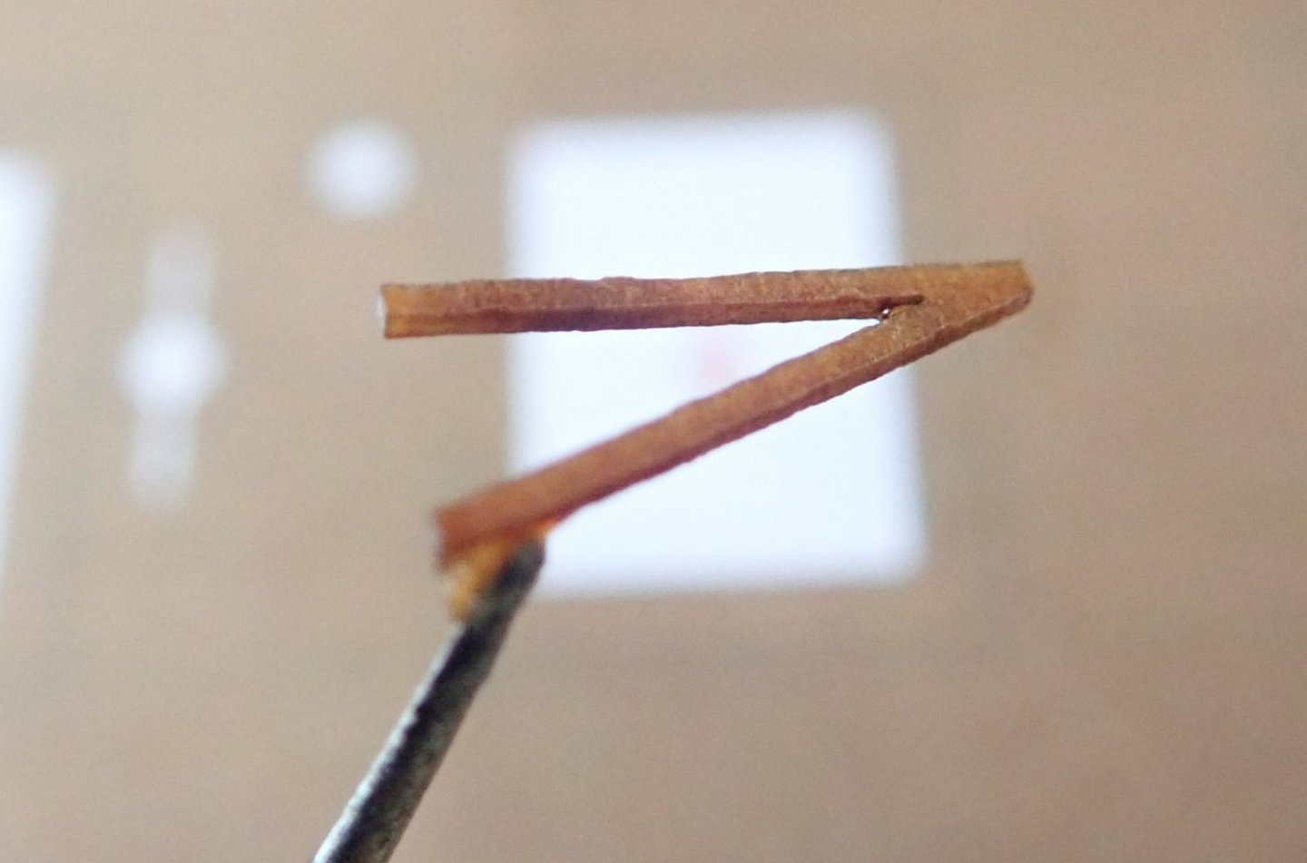
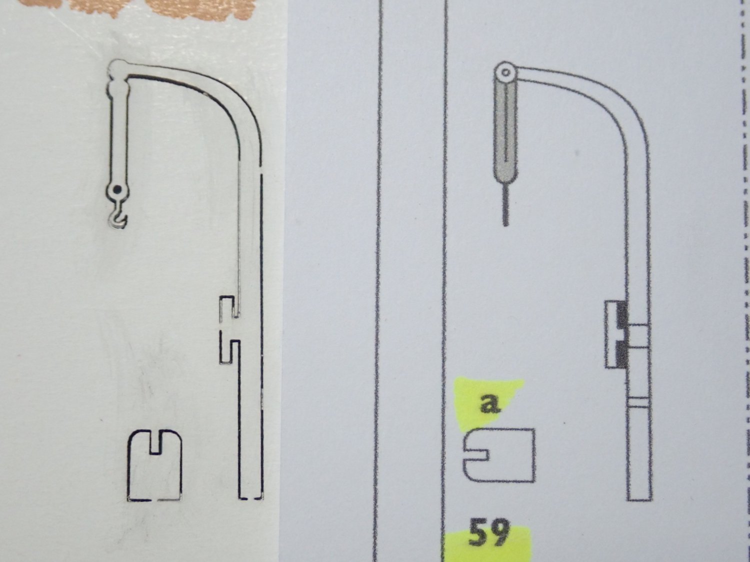
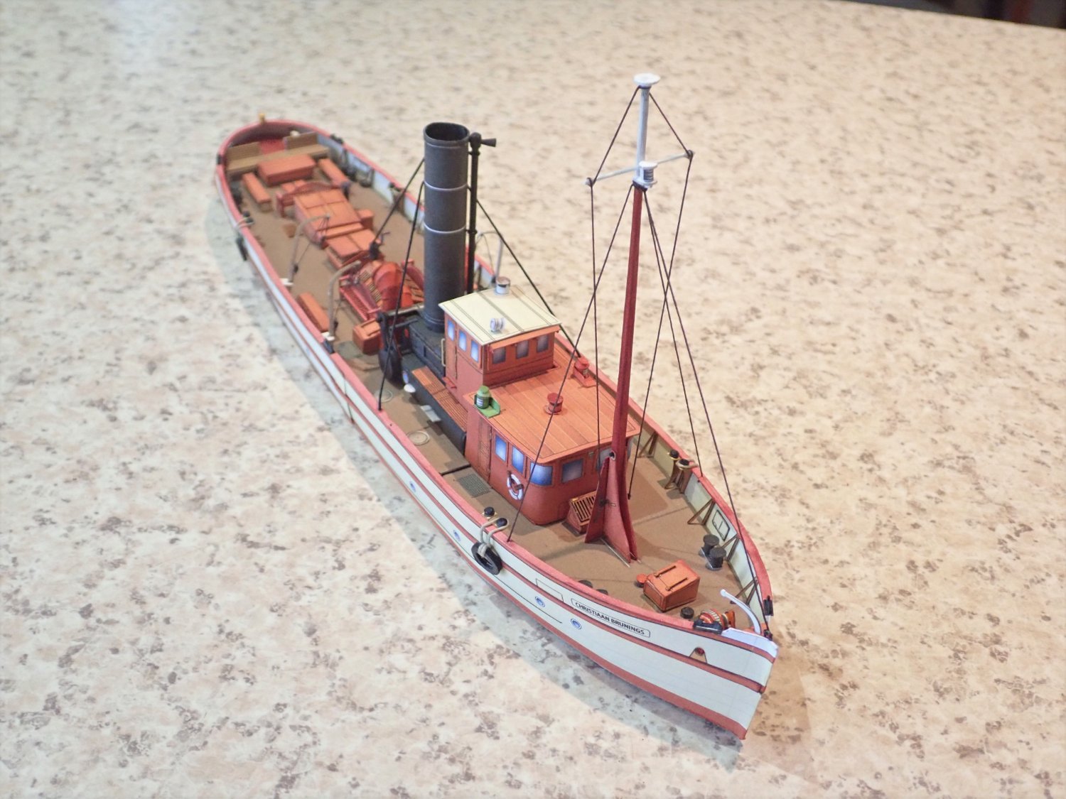
Thanks for the likes. There are four davits amidships and one at the bow. All are provided as prints or lasercut. The photo shows a midship davit, the image on the left being the lasercut version while the printed one is on the right. The lifting tackle is shown as lines on the latter, but as a solid “bar” on the lasercut one. The appearance of neither appealed to me, so I decided to rig some actual tackle on the lasercut davits. The “bar” between the tip of the actual davit and the hook at its end was removed and thin thread was used for the tackle. Not easy and the results were not quite as I had hoped. The following photos show one of the rigged davits and all four in place. The bow davit was left unadorned. Finally, the mast. This was fashioned from a length of strip wood, following the provided template. The base is made up of three printed parts, and would allow the mast, on the actual vessel, to be lowered before passing under a bridge (as was the funnel). The masthead light was made and rigging added. I found a photo on the net which showed the rigging more clearly than did the kit illustrations. So that’s the finish of this build. A little bit difficult in parts, the instructions are vague in places and the illustrations could definitely be improved. But I enjoyed it. Cheers


- 23 replies
-
- 9
-
-
- card
- World of Paperships
- (and 2 more)
-
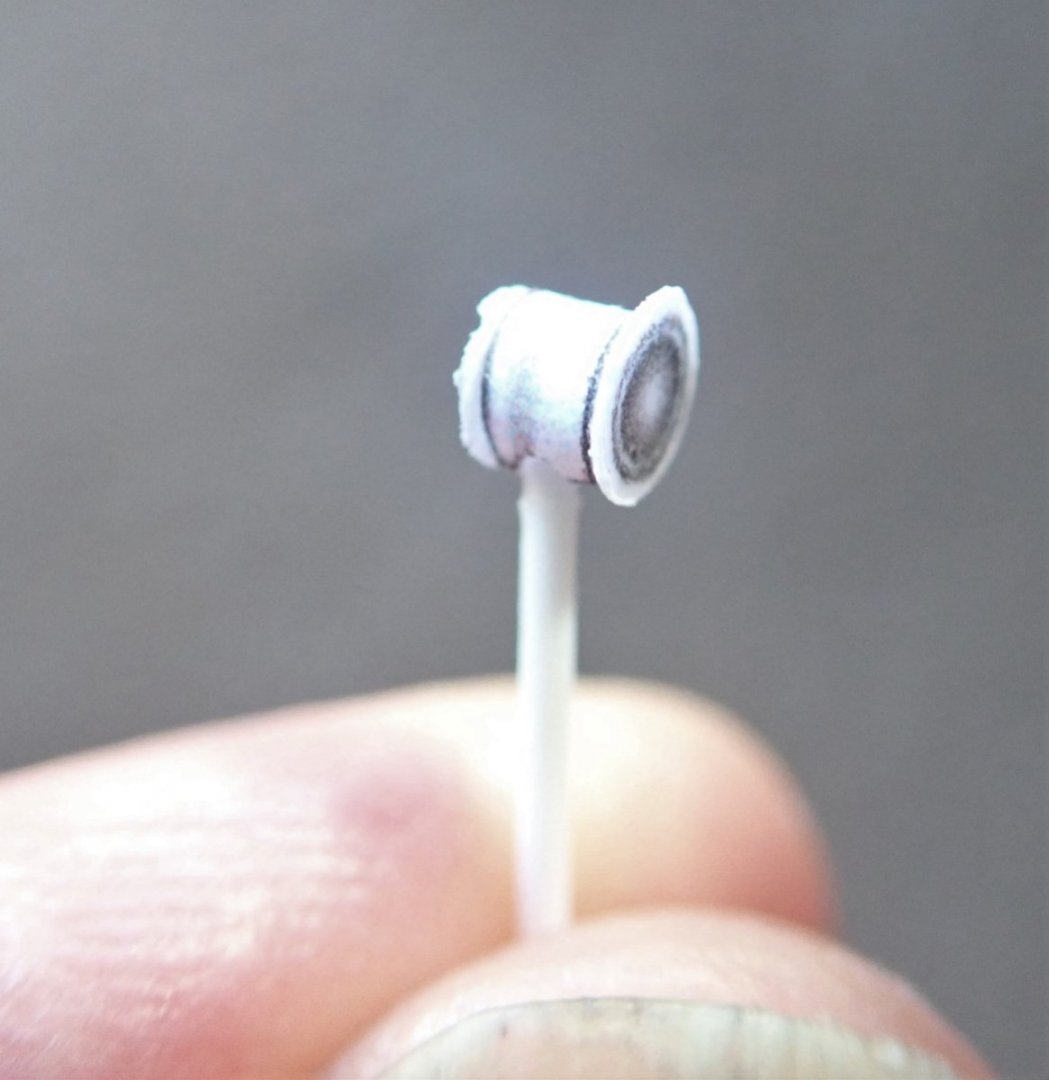
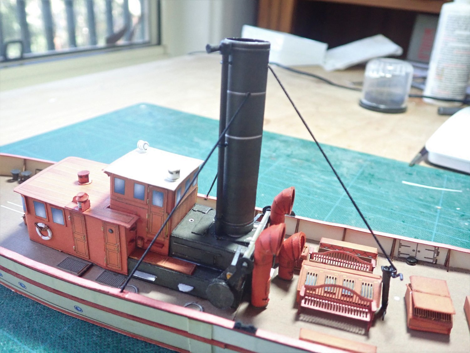
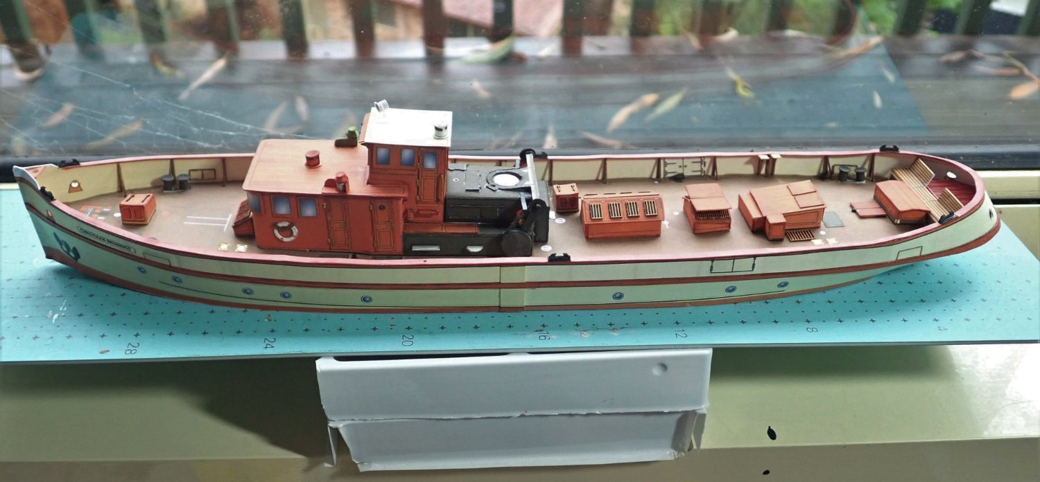
Thanks for the likes, and the comments Captain Slog, Chris and Ian. Not much to tell this time. The funnel is in place. This was a simple rolled tube with a joiner on the inside. The whistle that is alongside the funnel was made from a dowel as suggested in the instructions. A printed version came with the kit, but trying to roll a long, three mm diameter tube, proved to be beyond my skills. In particular the actual whistle at the top of the tube looked weird as it was an integral part of the print. The latter was therefore made from a short length of dowel. The completed whistle was attached to the funnel using small brass eye pins. The three guy ropes are elastic thread and the one running towards the stern is attached to a hand winch used when the funnel needed to be lowered. That winch is a card tube with the handle made from styrene rod. Also visible are two bench seats that were laser-cut. That’s it for now, not a lot more before it’s finished. Cheers

- 23 replies
-
- 5
-
-
- card
- World of Paperships
- (and 2 more)
-
Ahhhh, I just realised after looking at that photo that I've left off the bits that represent the outer drums!!! I'll have to fix that tomorrow. Thanks for that photo Jan.
- 23 replies
-
- 3
-
-
- card
- World of Paperships
- (and 2 more)
-
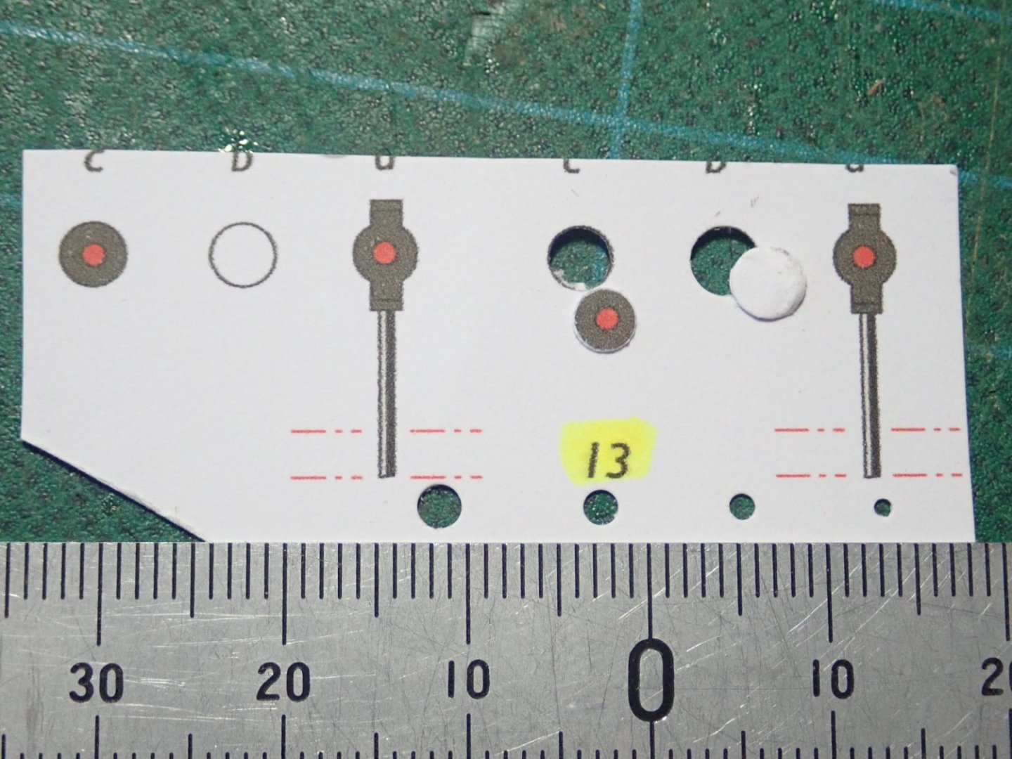
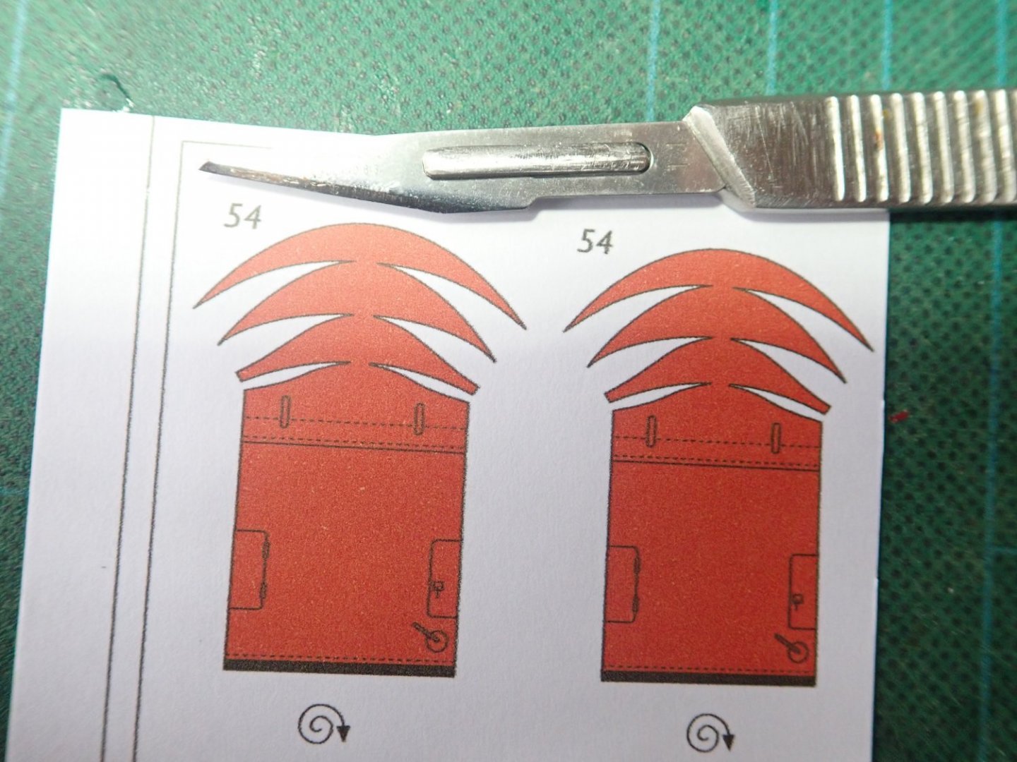
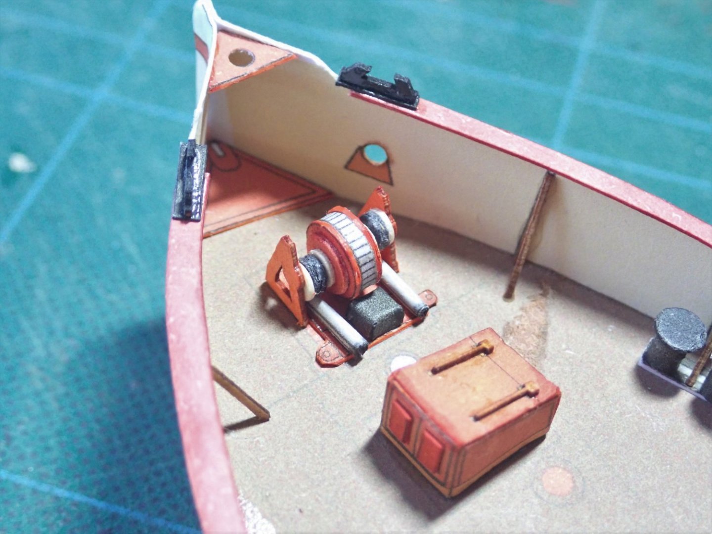
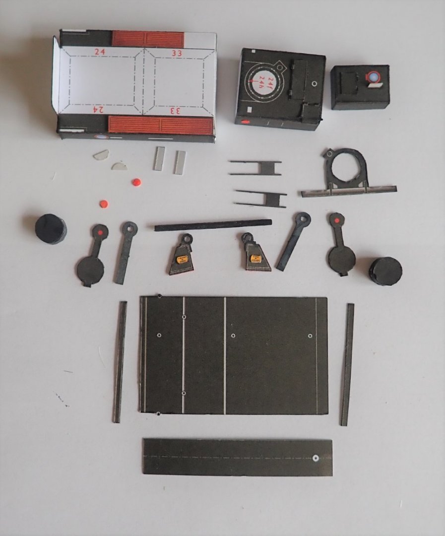
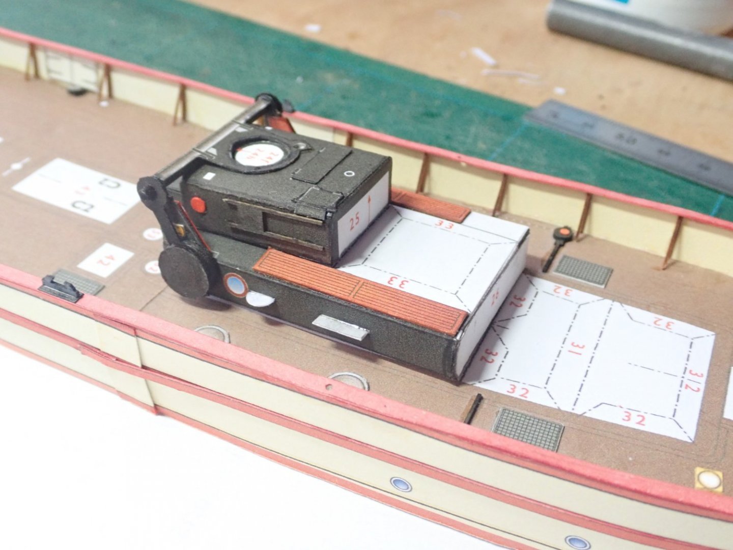
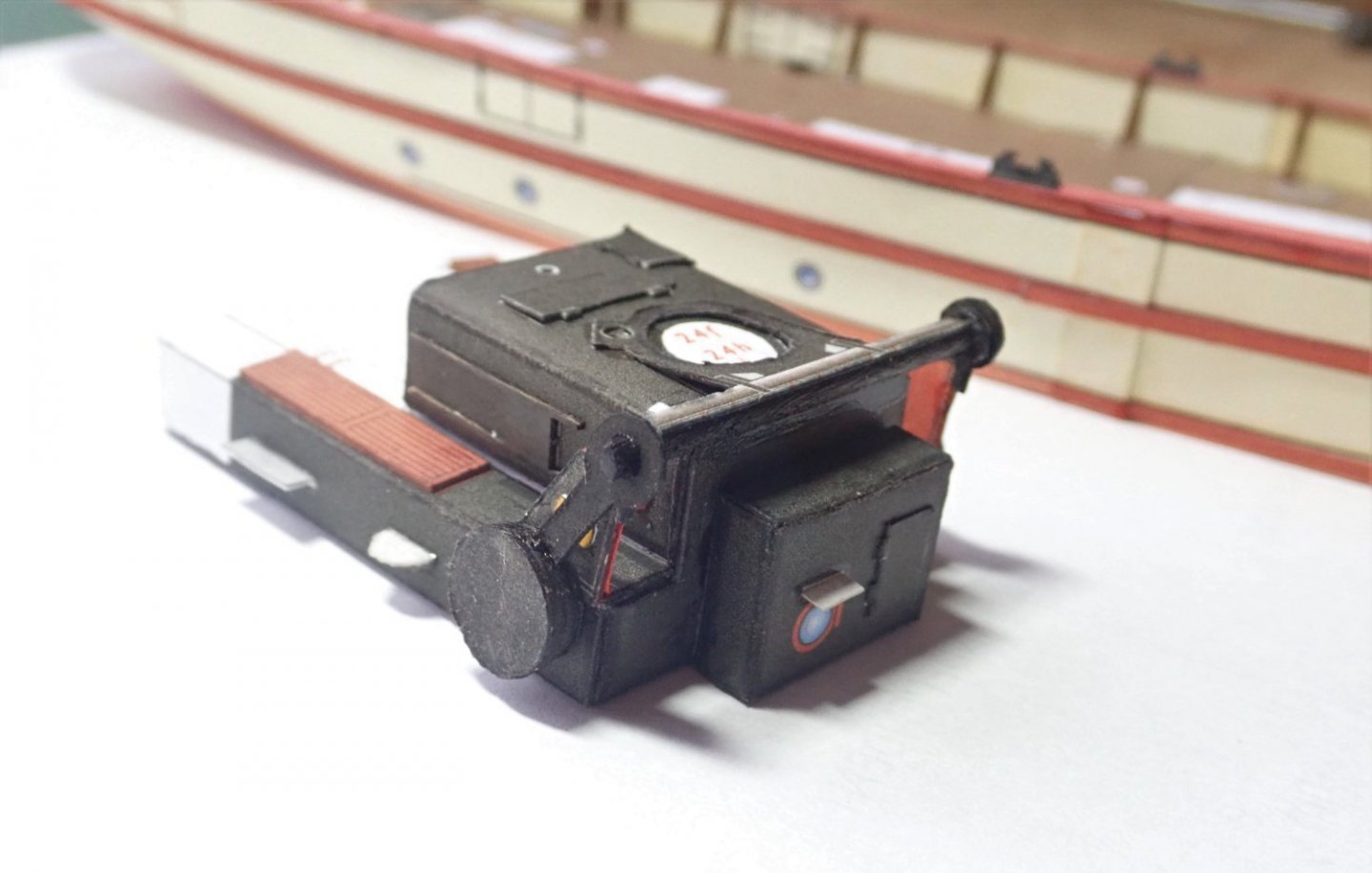
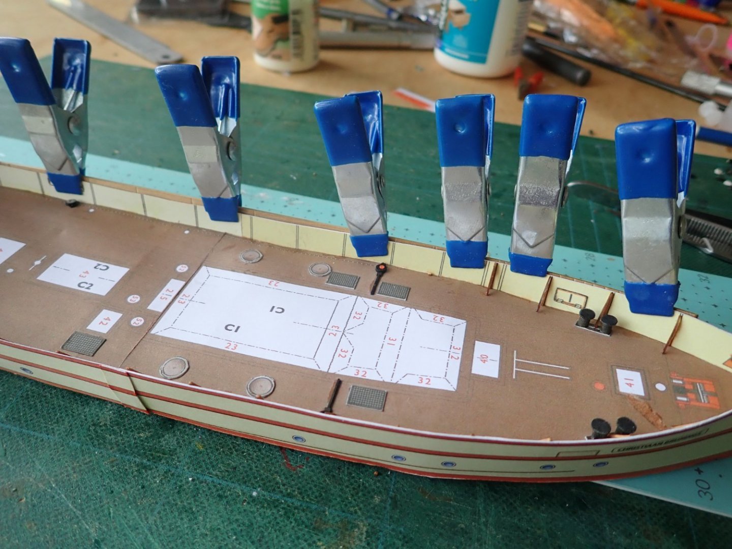
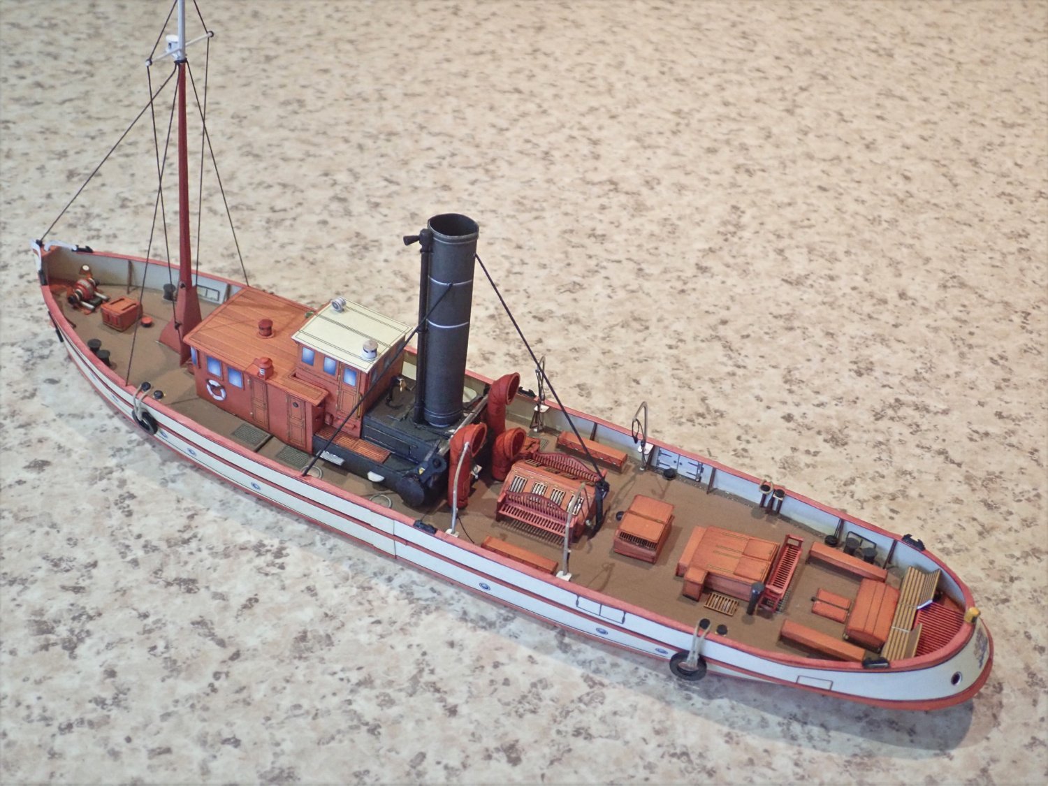
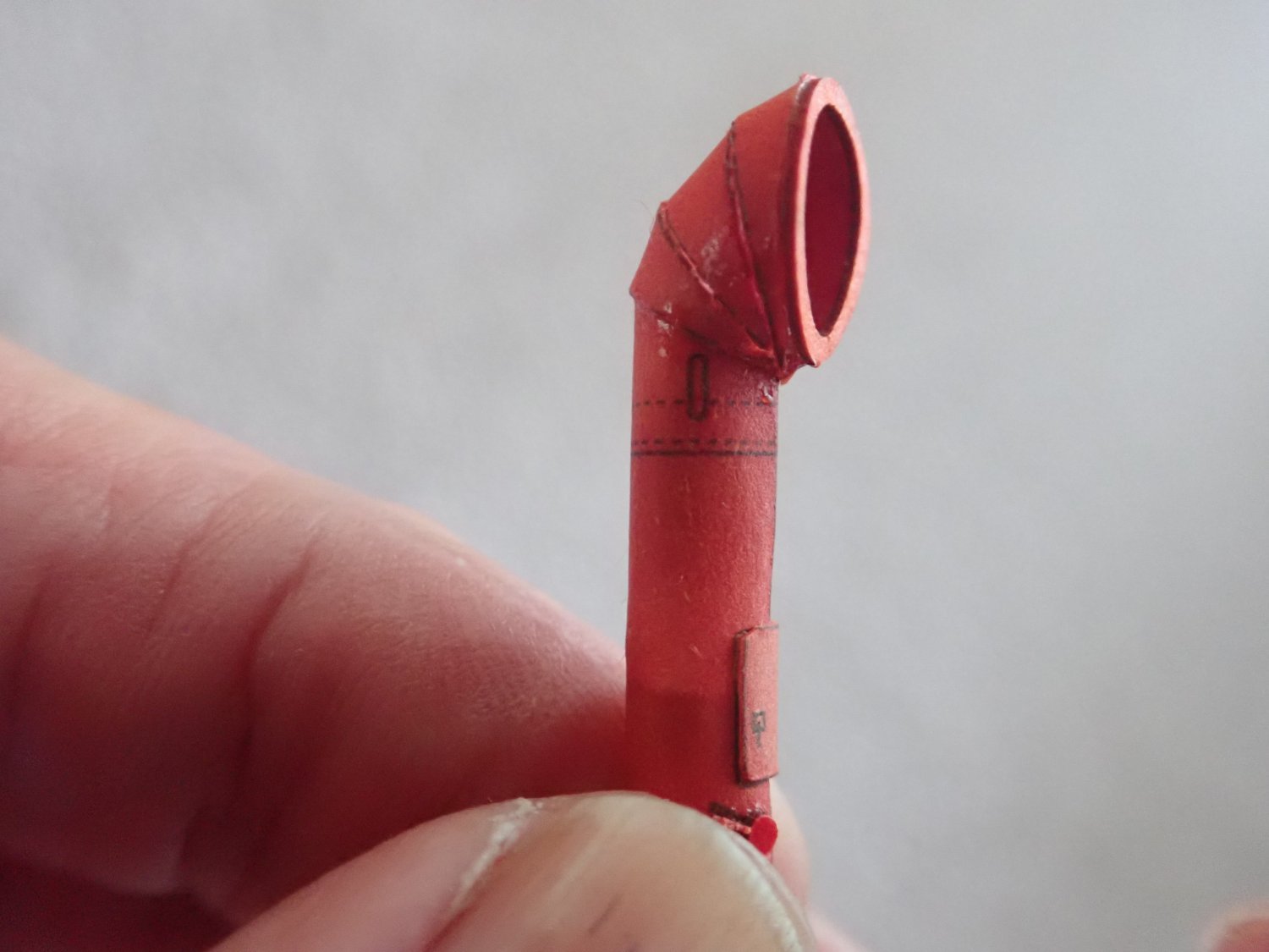
Thanks for all the likes. The next job was to make the cowl vents - three of them. The kit provides three choices for these - a simple folded version, a slightly more complicated version with a cylindrical body and a simple hood, or the complicated one with the hood made up of individual segments that have to be folded and glued together. Two of them as printed are shown here. I went for these. Bending and gluing the segments was an exercise in patience. To make it a little easier, the vent was held down on a steel rule with a small modified alligator clip (the teeth had been flattened). A finished vent, and the three of them in place. Next thing to be made was the bow winch. Again the kit provides options, simple and detailed. On the left is the detailed version with the simple version on the right, and again I’m doing the detailed one. The only guide to building this is contained within the red square (no actual instructions), and it hasn’t helped to find that some parts are mis-identified. Nevertheless, it was completed and glued in place. Cheers
- 23 replies
-
- 10
-
-
- card
- World of Paperships
- (and 2 more)
-
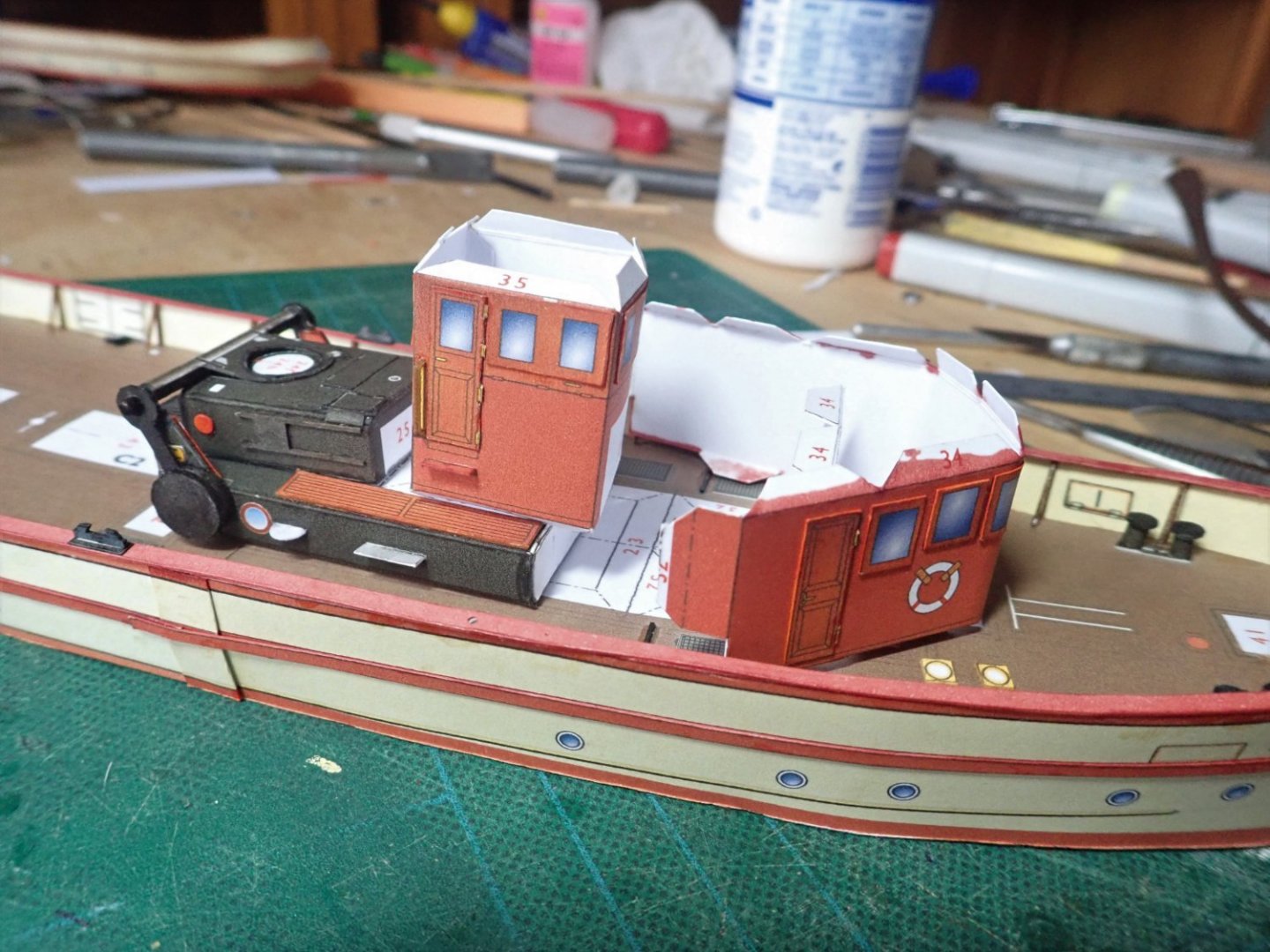
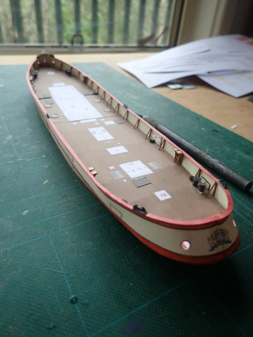
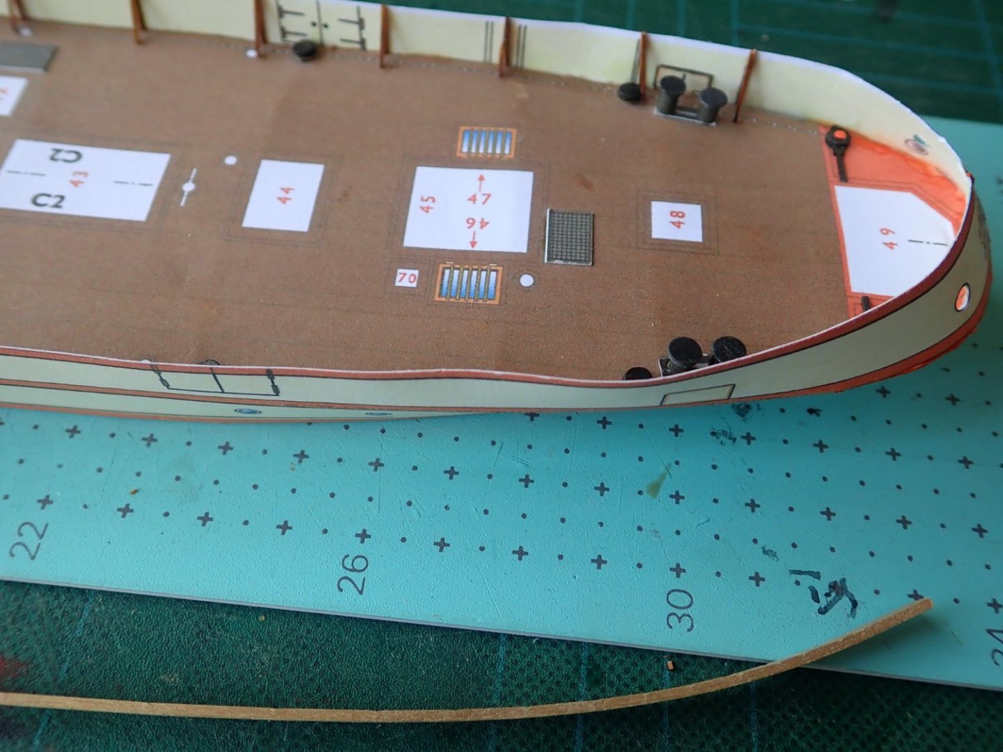
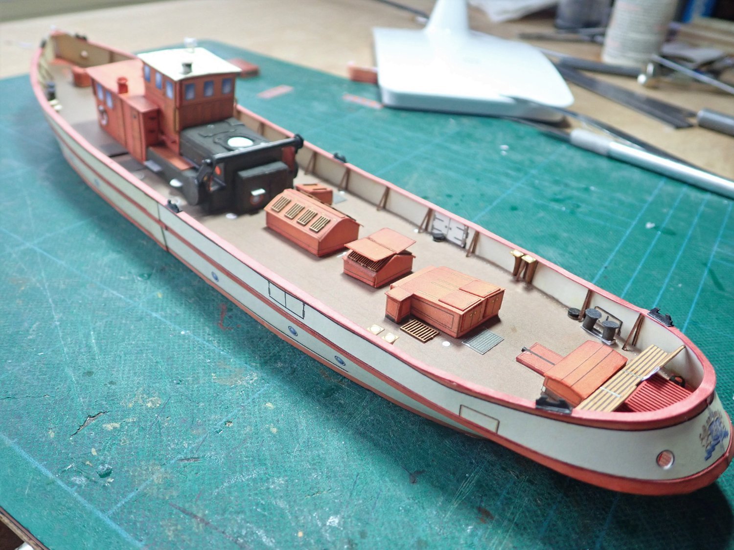
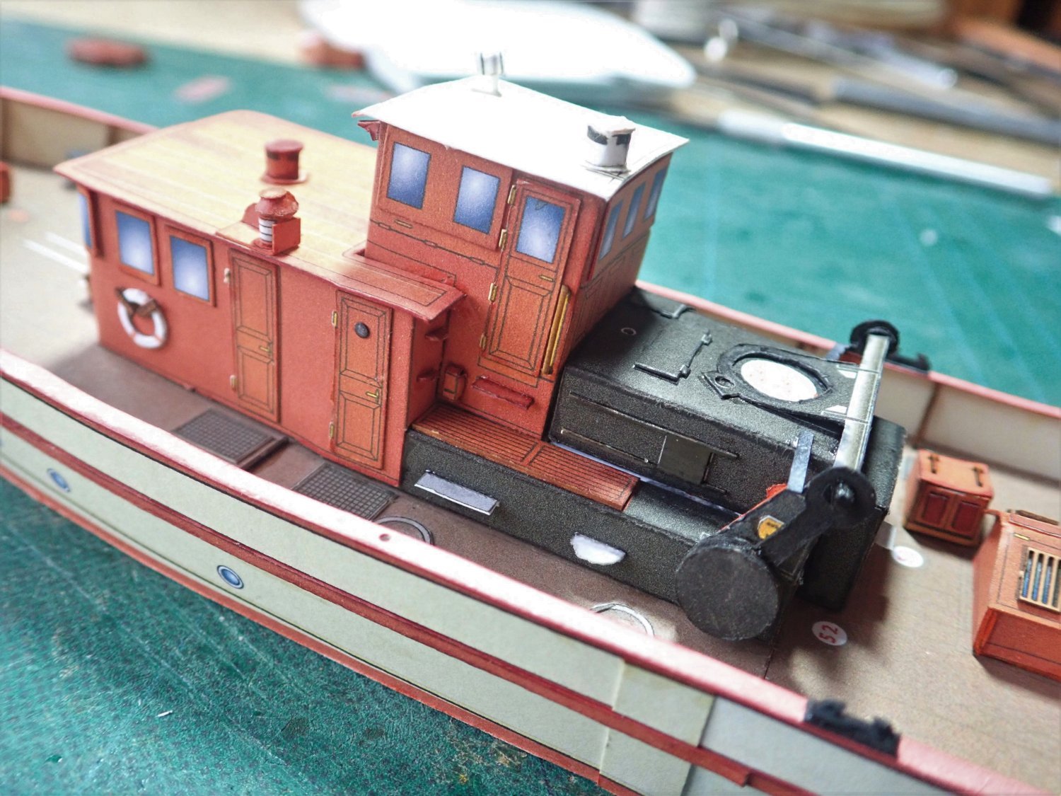
Thanks for the likes. The wheel house, cabin and boiler room loosely in place. I forgot to take photos of the next stage, so skipping ahead a little…The parts for the searchlight and the completed unit. This photo shows the printed parts for the navigation lights. The boat with most of the deck fittings in place. Also visible are the navigation lights, the searchlight and roof vents. The nav lights are not quite as I would like, but as they are only 4mm high, they’ll pass. The kit provides duplicates for the windows, doors, hatches and gratings and these can be overlaid on the basic printed part to add some depth. Cheers


- 23 replies
-
- 8
-
-
- card
- World of Paperships
- (and 2 more)
-
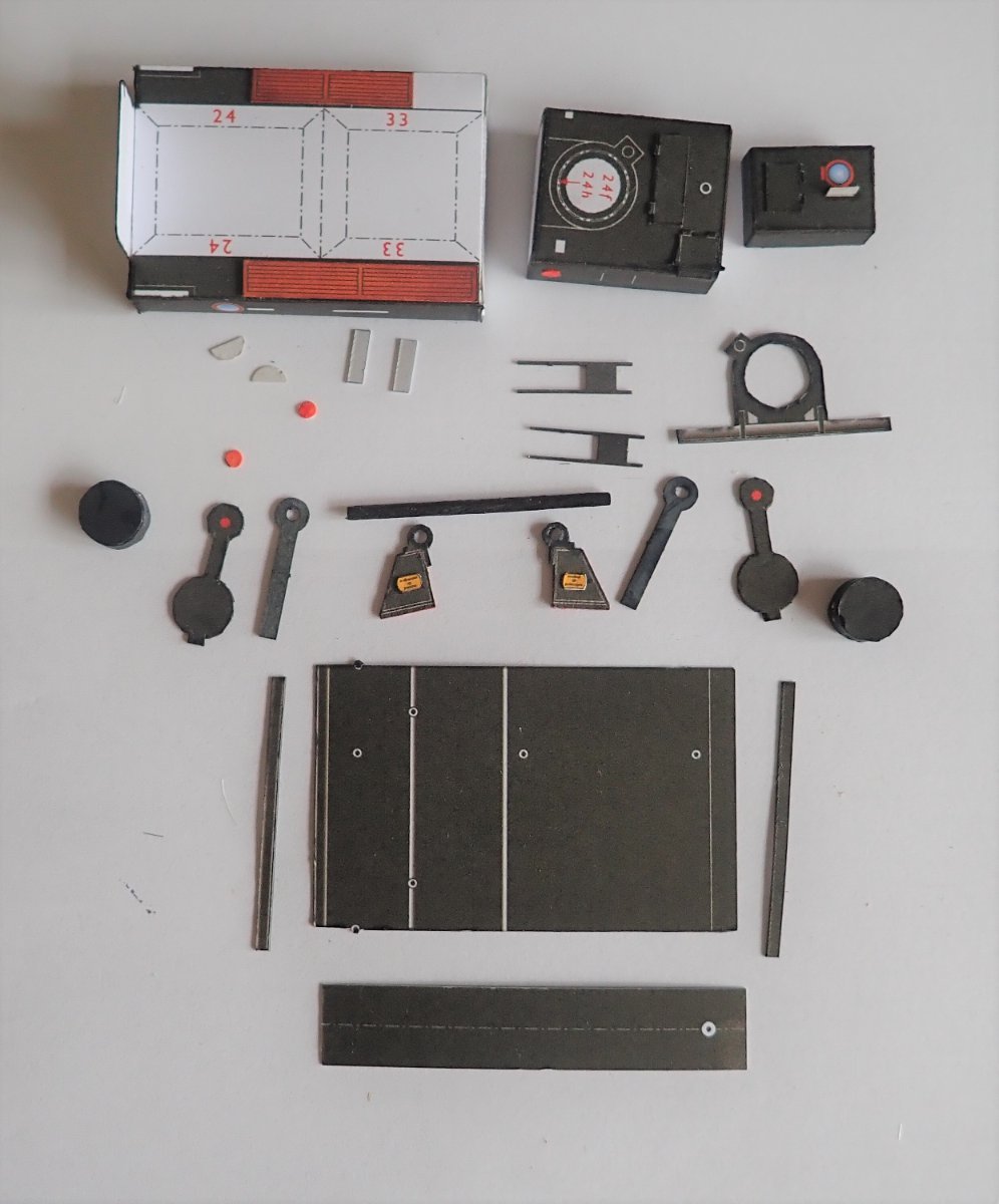
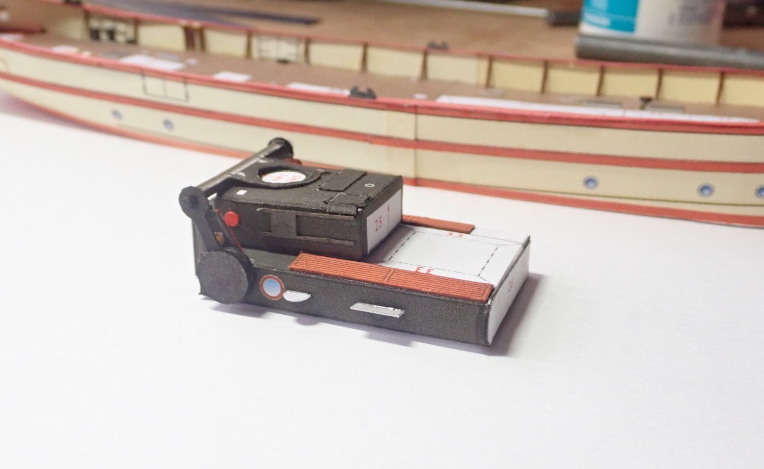
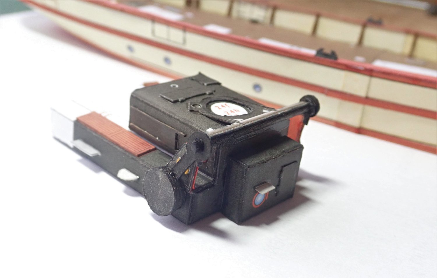
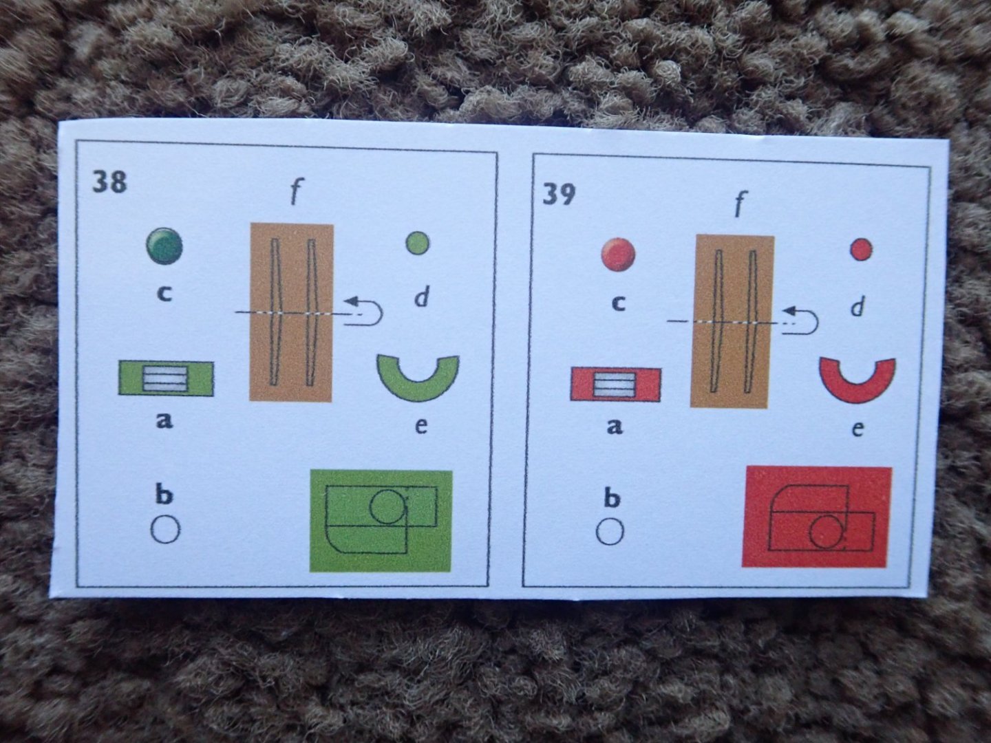
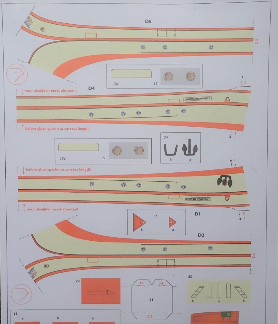
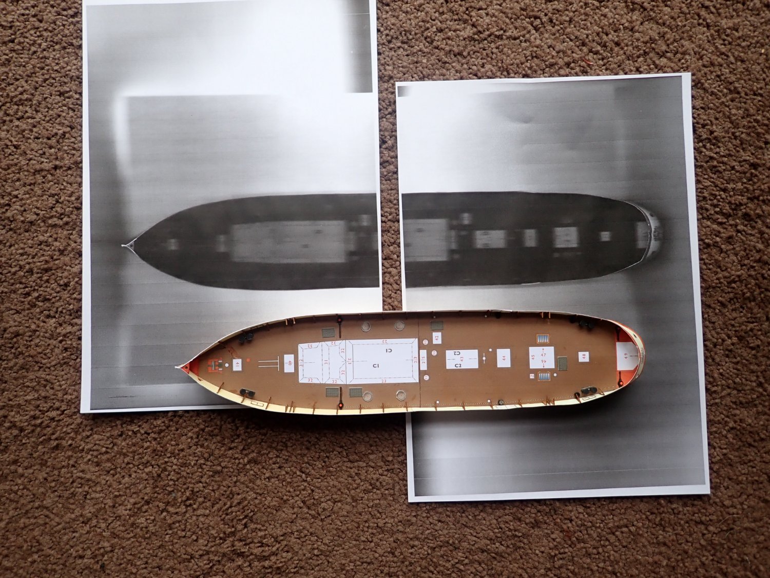
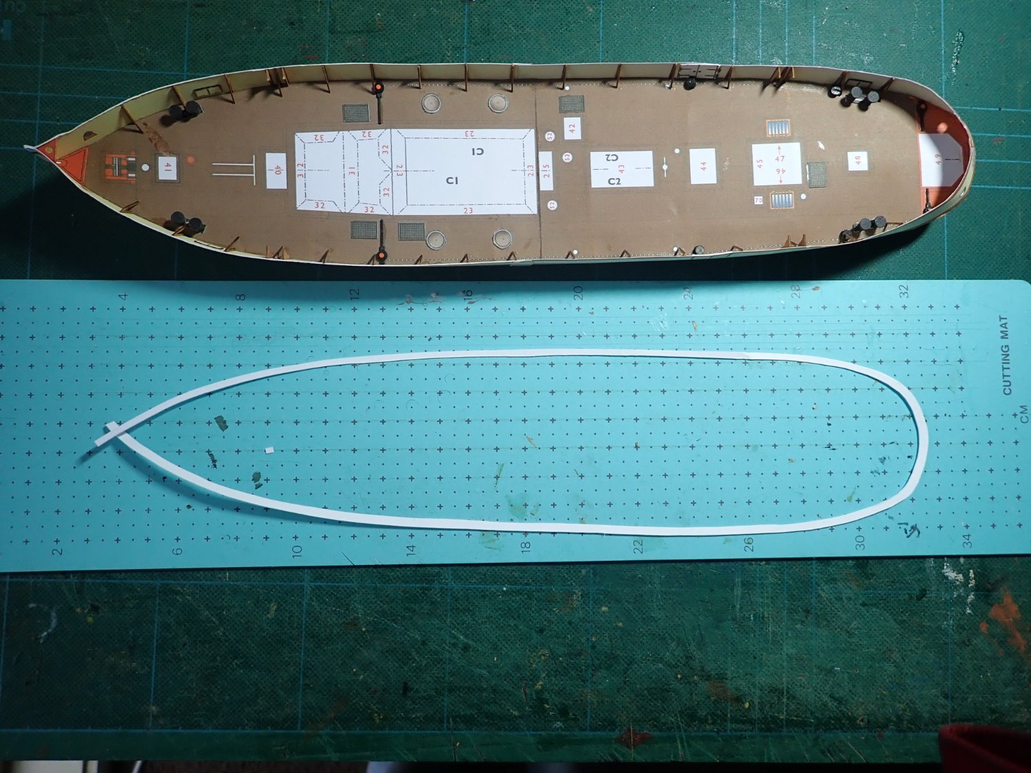
Thanks for the likes and your comment Rob. The next job was to glue the cap rail onto the top of the bulwarks. As supplied, this was in four pieces, but unfortunately, it didn’t fit, especially at the stern. Slight differences in my build would be the reason. So a new cap rail had to be made. The immediate problem was to get an accurate pattern of the top of the bulwarks. I couldn’t see that trying to trace the outline of the hull onto paper was going to work owing to the sheer of the deck and hence the bulwarks. The hull was not going to sit flat on the paper. So I decided to try photocopying the hull. The first photo shows the result of doing this and the second shows the new cap rail in one piece. Two attempts were required, the first not quite fitting. The cap rail in place. Also visible are six black fairleads on the rail - these are laser cut pieces. Next was the boiler house. The photo shows the partially complete unit, additional bits yet to be added and also the parts for the funnel. The latter can be made either fixed or pivoted so that it folds down aft. This was to allow the boat to pass under bridges. I decided to make the funnel fixed. The completed boiler house. The funnel is to go on top, and the rod that allows it to pivot is at the rear of the house, and the counter weights to balance the funnel are the large circular pieces on the end of the arms. Temporarily in place. Cheers


.thumb.JPG.2d226b93f606b3d9030abd8fa0a7b9c7.JPG)

- 23 replies
-
- 11
-
-
- card
- World of Paperships
- (and 2 more)
-
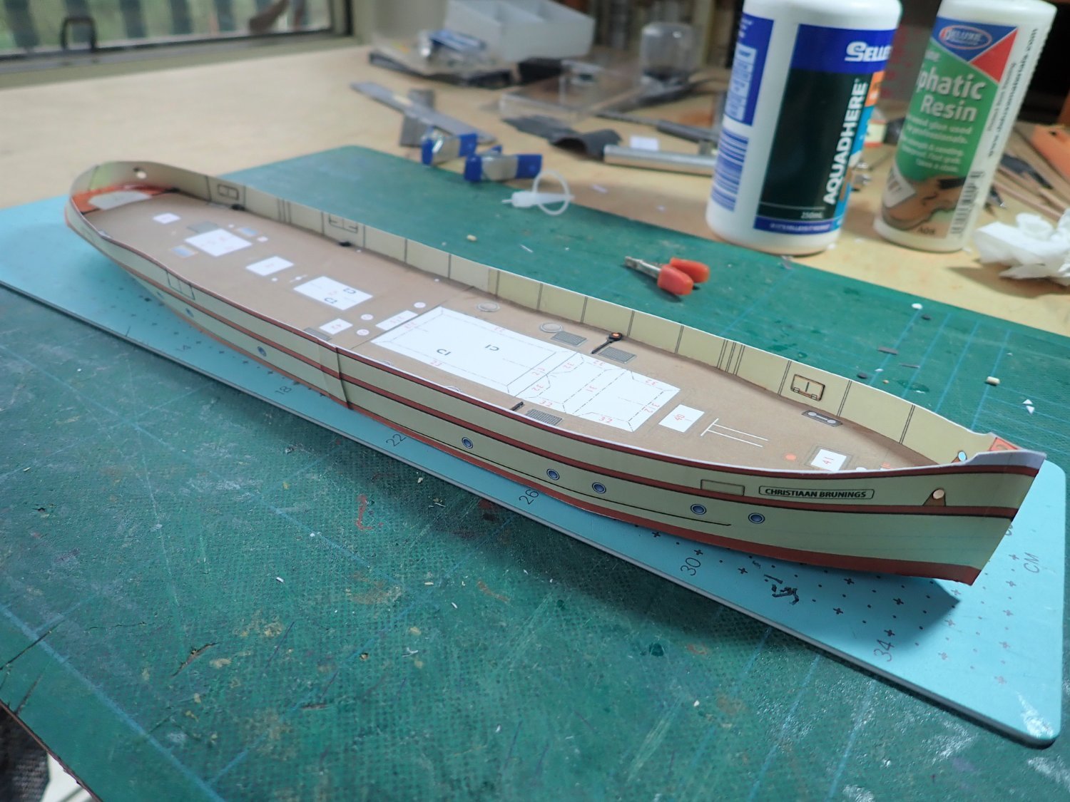
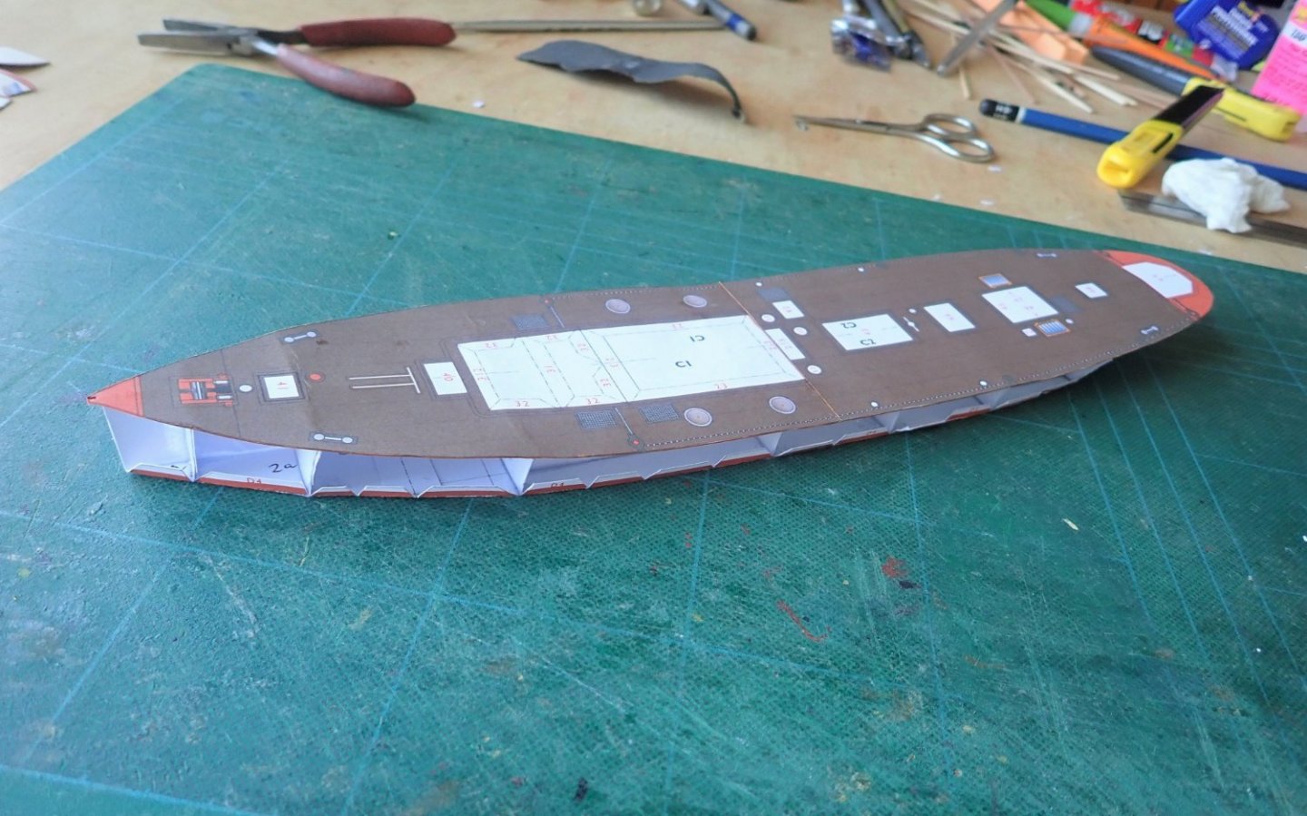
Thanks for the likes and Rob, you’re very welcome. The bulwark supports are laser cut and quite delicate. One is shown below. The waviness of the port bulwark is apparent in this photo. Also shown is the strip of pre-bent wood I used to hold and straighten the bulwark before gluing the supports in place. Those on the starboard side have already been done. A few small deck items have been placed. The strip of wood clamped to the port side with a few supports in place. The hull with both sides complete. Cheers

- 23 replies
-
- 7
-
-
- card
- World of Paperships
- (and 2 more)
-
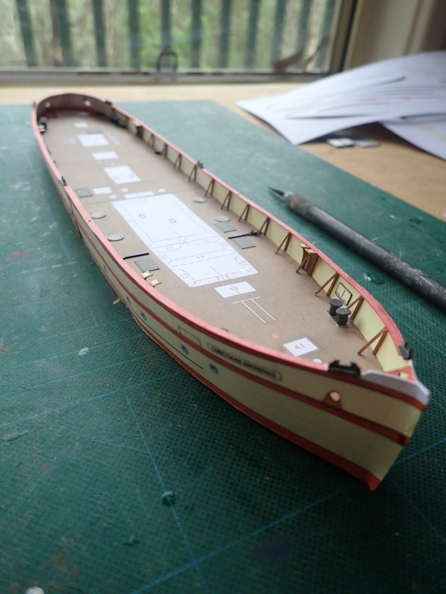
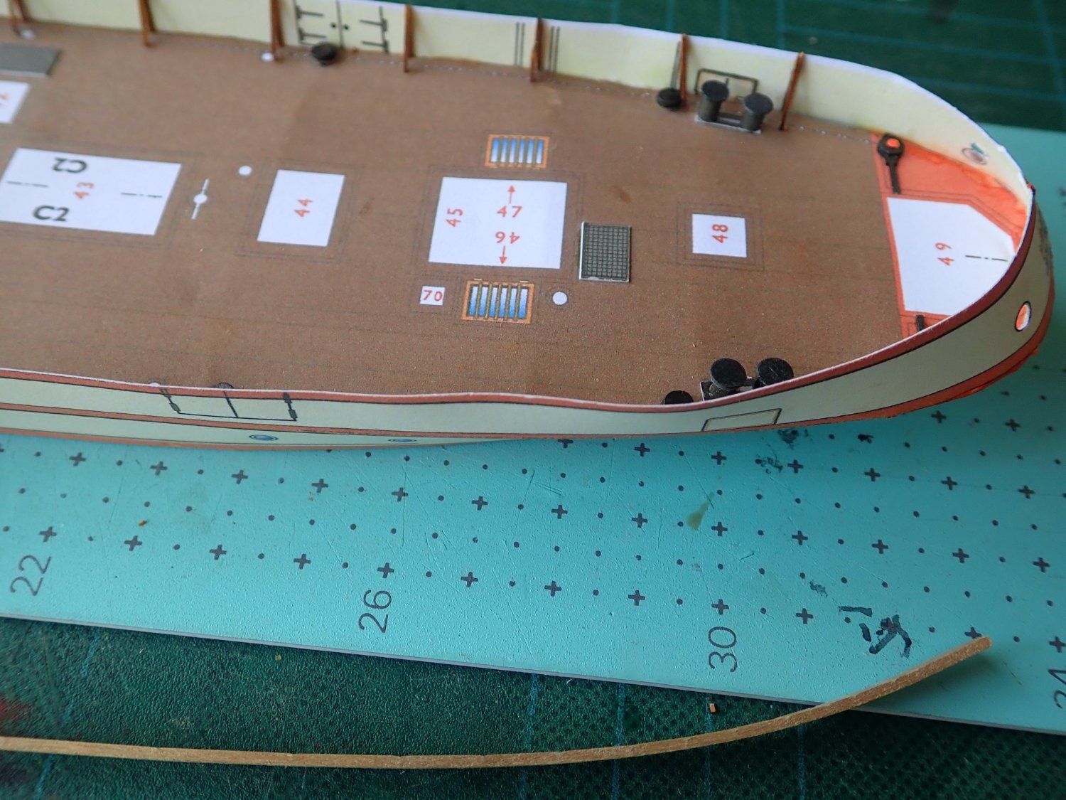
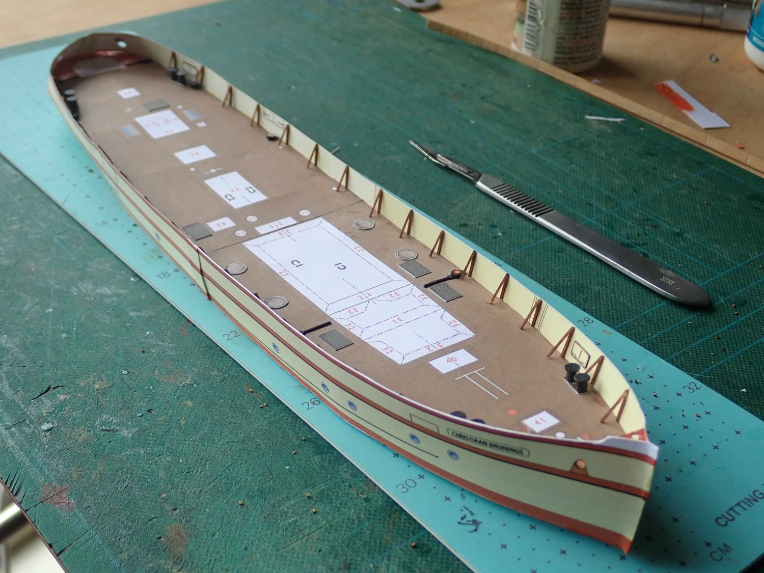
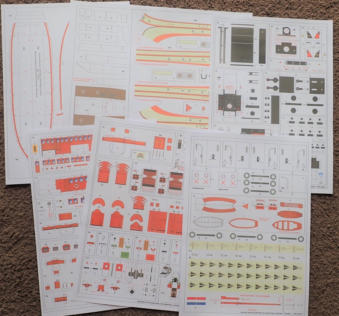
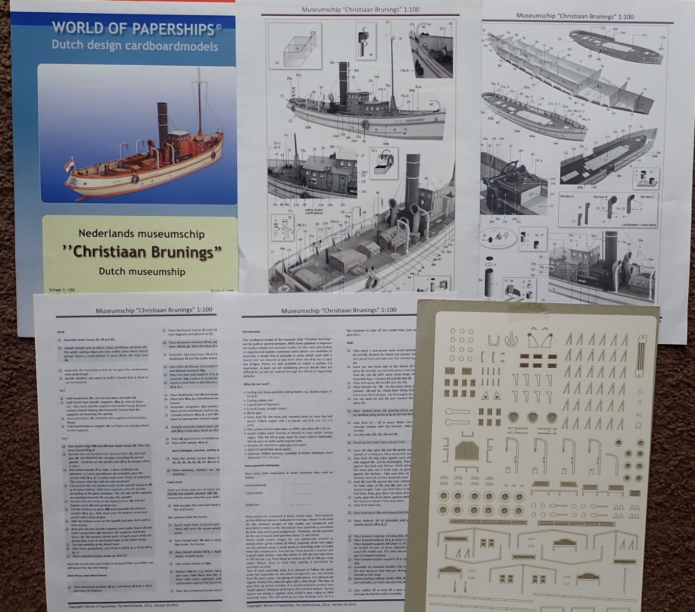
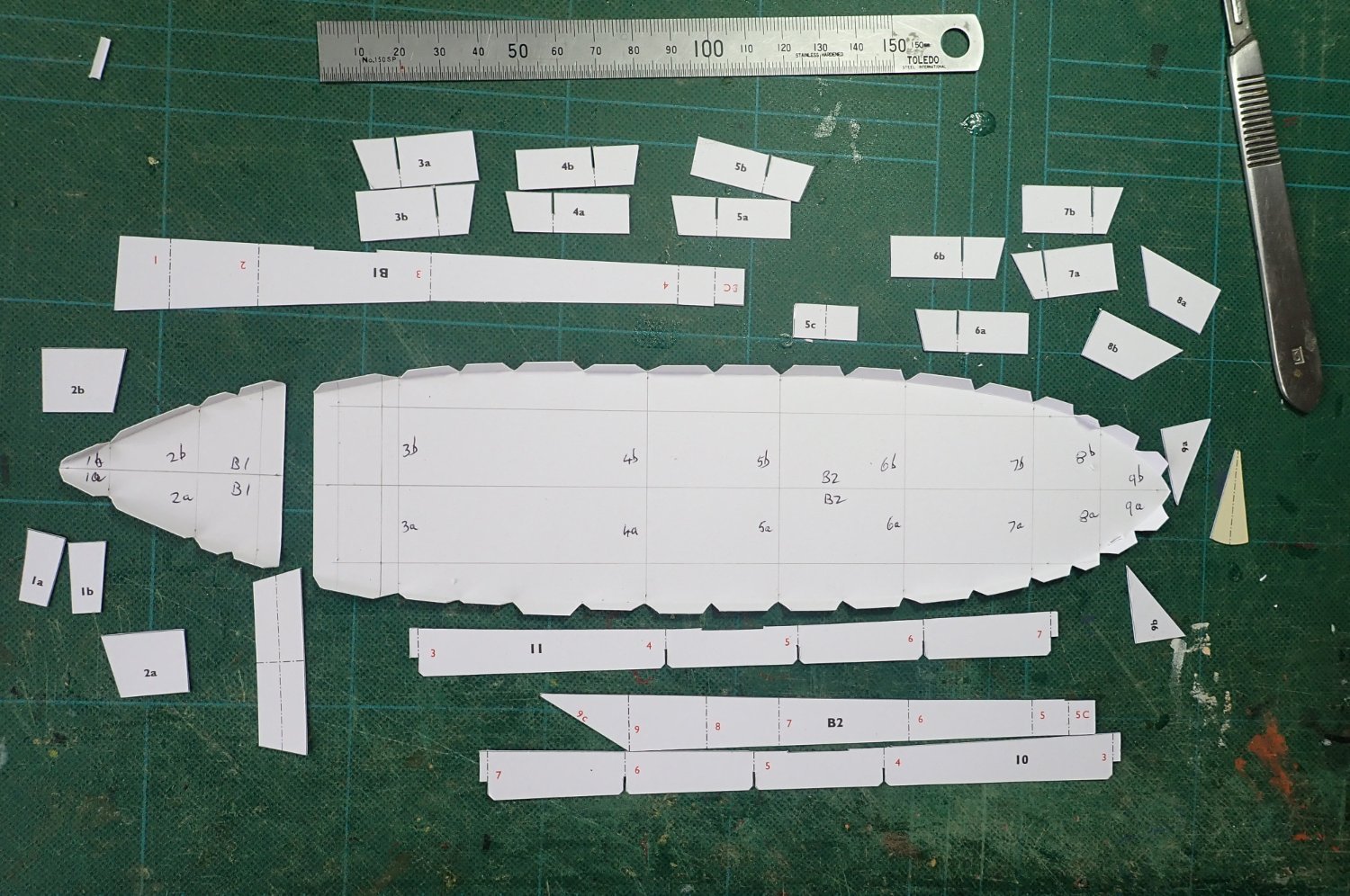
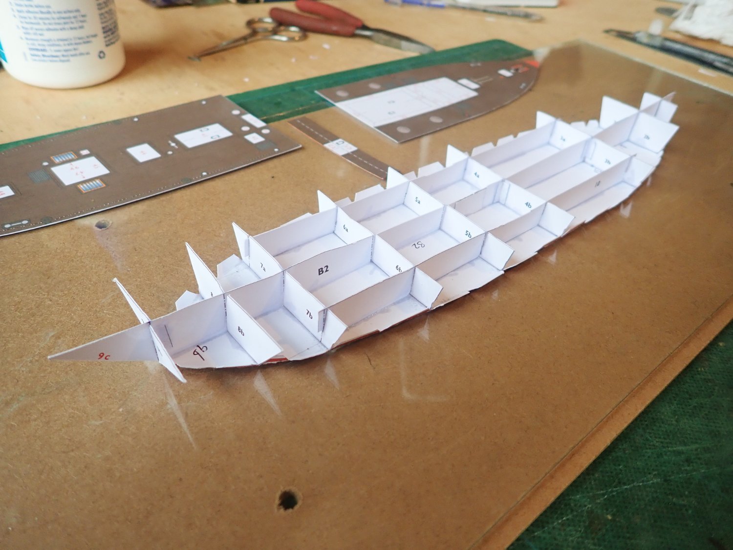
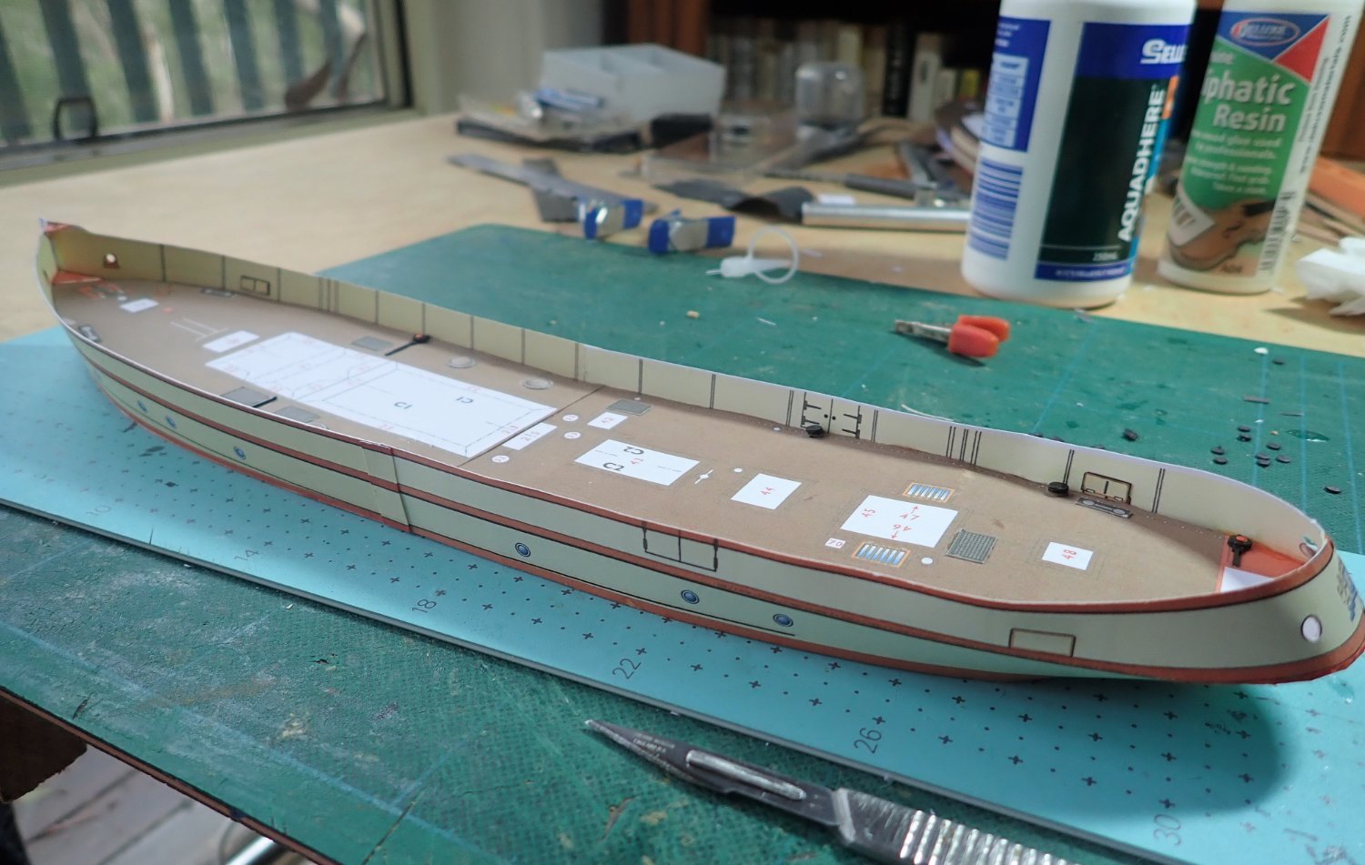
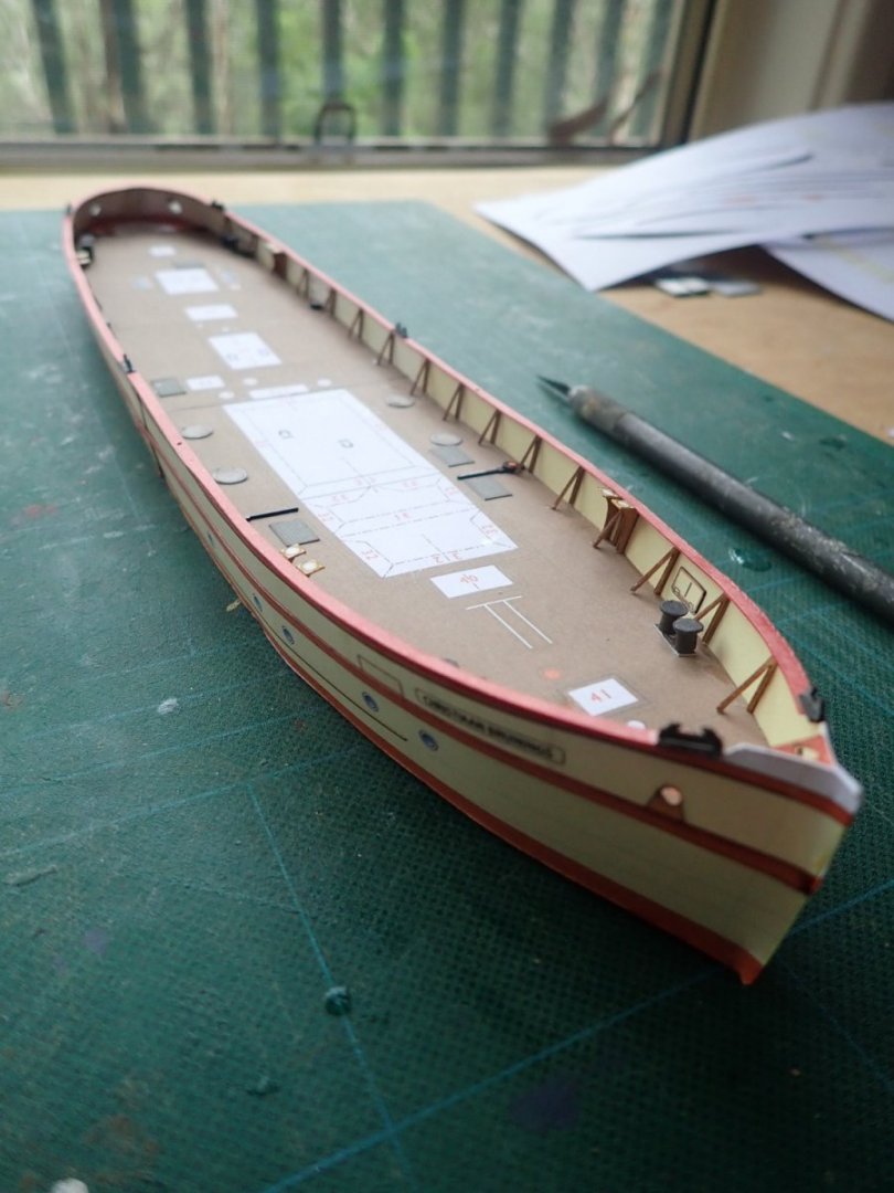
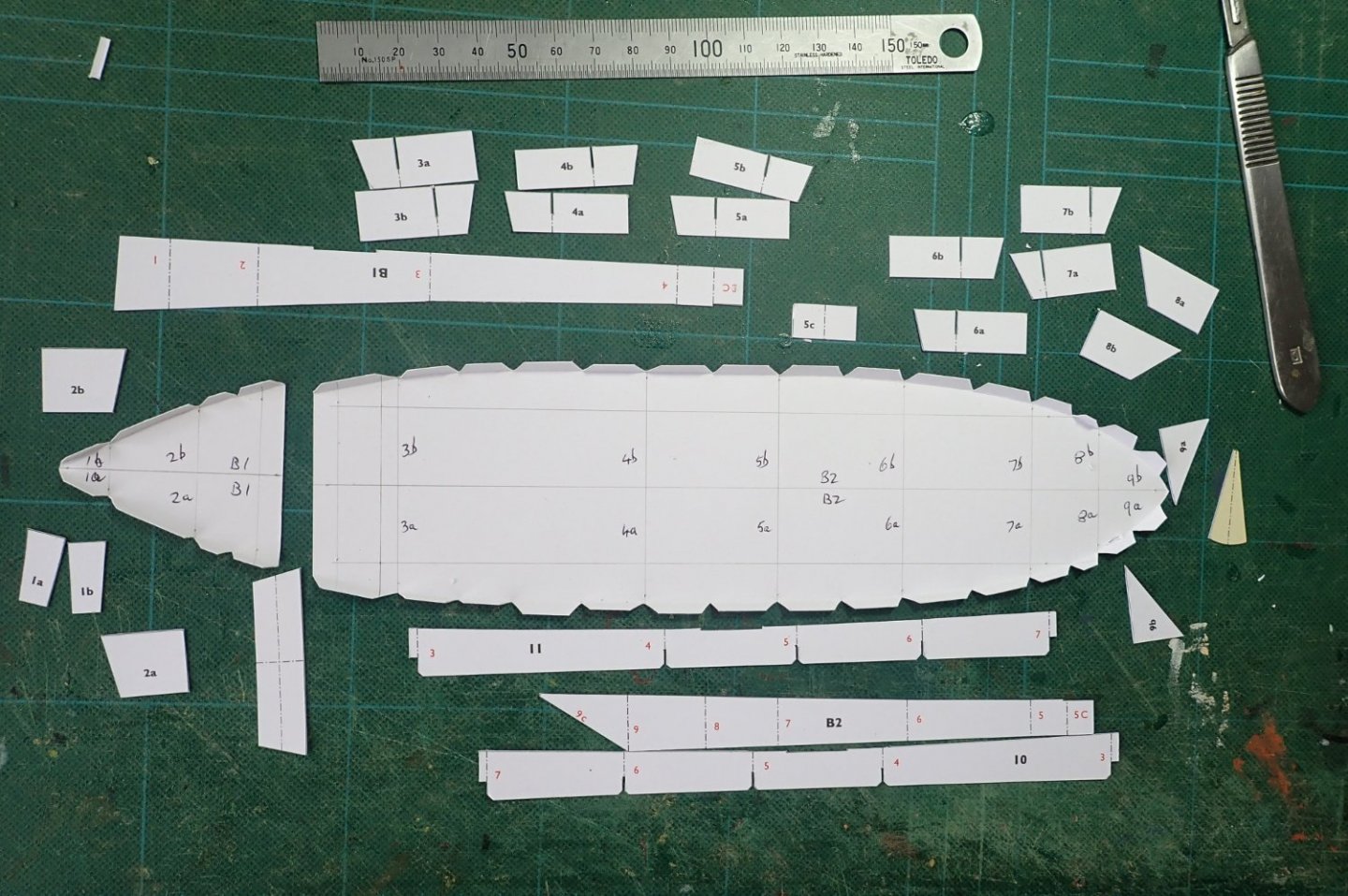
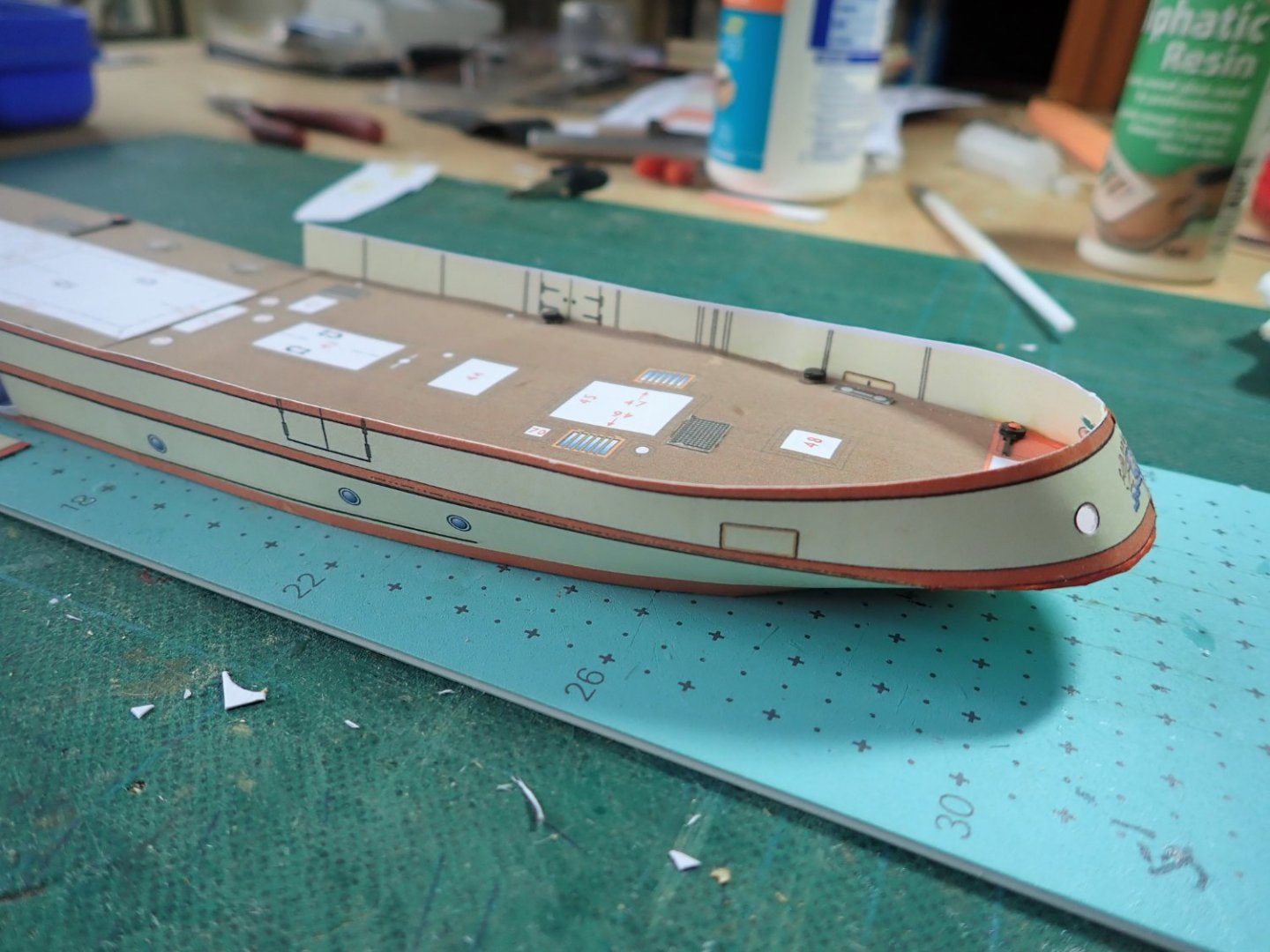
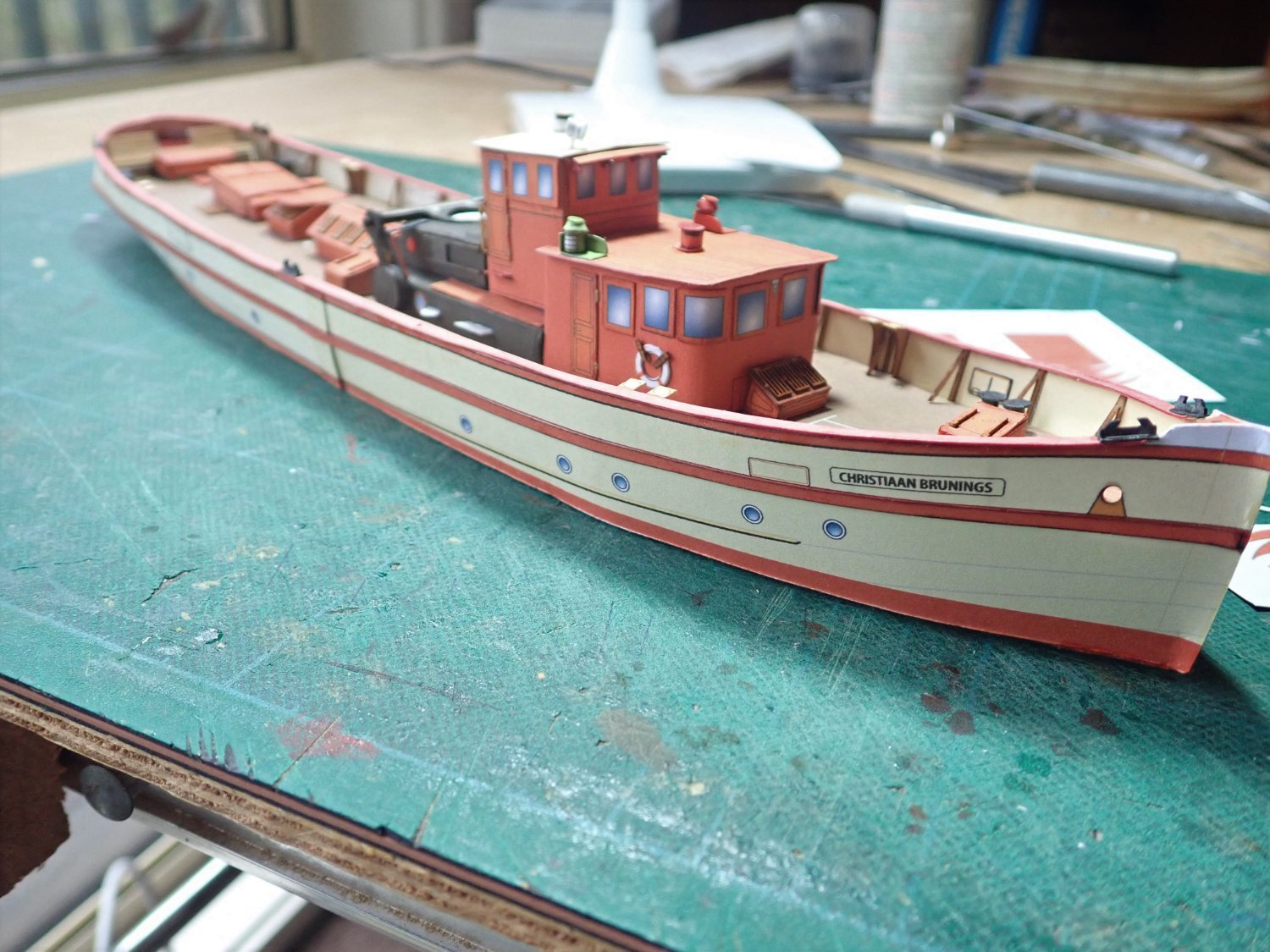
The Christiaan Brunings was commissioned in 1900 at an Amsterdam shipyard, with luxury accommodation (including a marble fireplace) and was apparently used as a “directorate ship”. It was also suitable as an icebreaker. The initial engine was compound steam, replaced in 1998 with a Scottish twin coal-fired boiler. After the war, it was used as a measuring vessel by the Dutch Government until 1968. It was then offered to the Dutch Historical Maritime Museum Association, and since then has been a museum ship. The kit from World of Paperships contains seven pre-printed sheets of A4 plus one sheet of laser-cut details. Some of the sheets are printed on both sides, making backup tricky. There are two and a half sheets of instructions and two illustrated sheets. The printed sheets look to be very good, the instructions we’ll see, but the illustrated sheets lack some clarity. The first photo shows the bare hull parts cut out ready for assembly, while the second shows the basic hull assembled. The hull with the two piece deck in place. The hull sides are in two pieces, within some obvious compound curves at the stern. The stern done. Some minor deck details have been added as well. Both sides are complete. The bulwarks are somewhat wavy, hopefully this will be corrected when the bulwark supports are added. Cheers


- 23 replies
-
- 9
-
-
- card
- World of Paperships
- (and 2 more)
-
Looking for a card model of the Arizona
Richard44 replied to Dion Dunn's topic in Card and Paper Models
Try here if you're not in a hurry - somethings are out of stock. https://www.kartonmodellbau.de/catalogsearch/result/?q=Arizona -
Thanks for all the likes and comments. B.E., with your skills, amply shown yet again with your Sphinx build, you would have no problem in building a card model. Chris, your models inspire me. I'll later be following your paper trail with HMV's Waratah, though at the moment it's been stuck at Frankfurt airport for a month now.😙. Cheers everyone.
- 18 replies
-
- 1
-
-
- card
- World of Paperships
- (and 2 more)
-
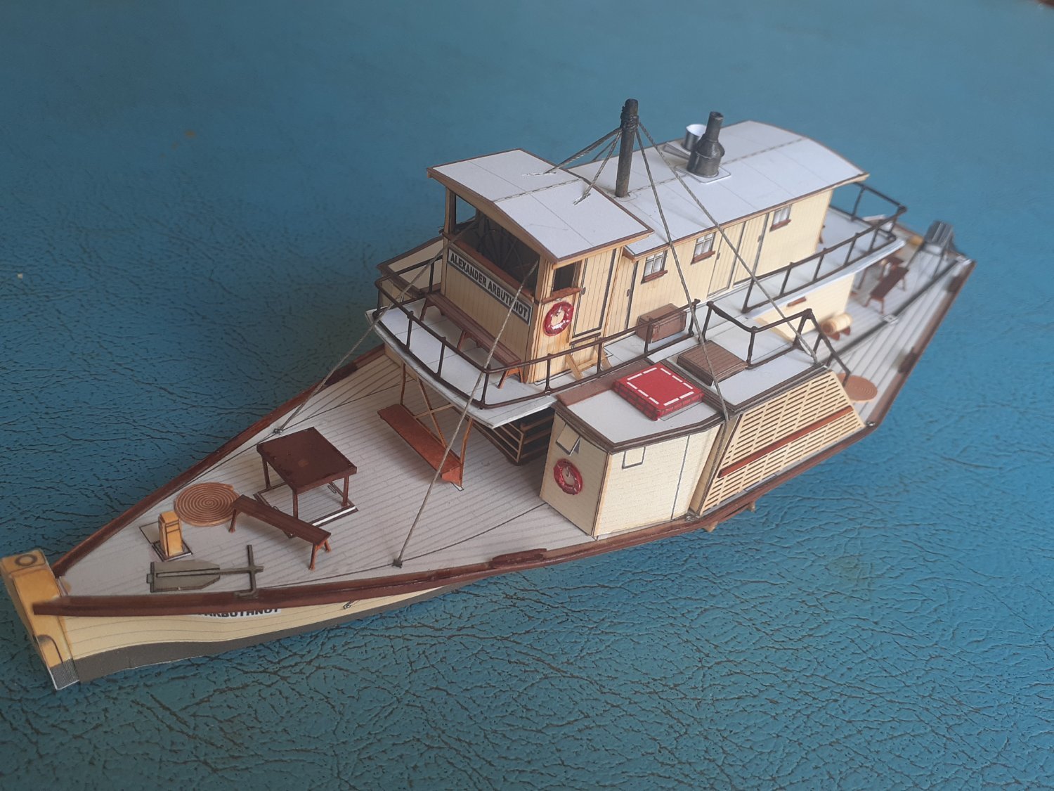
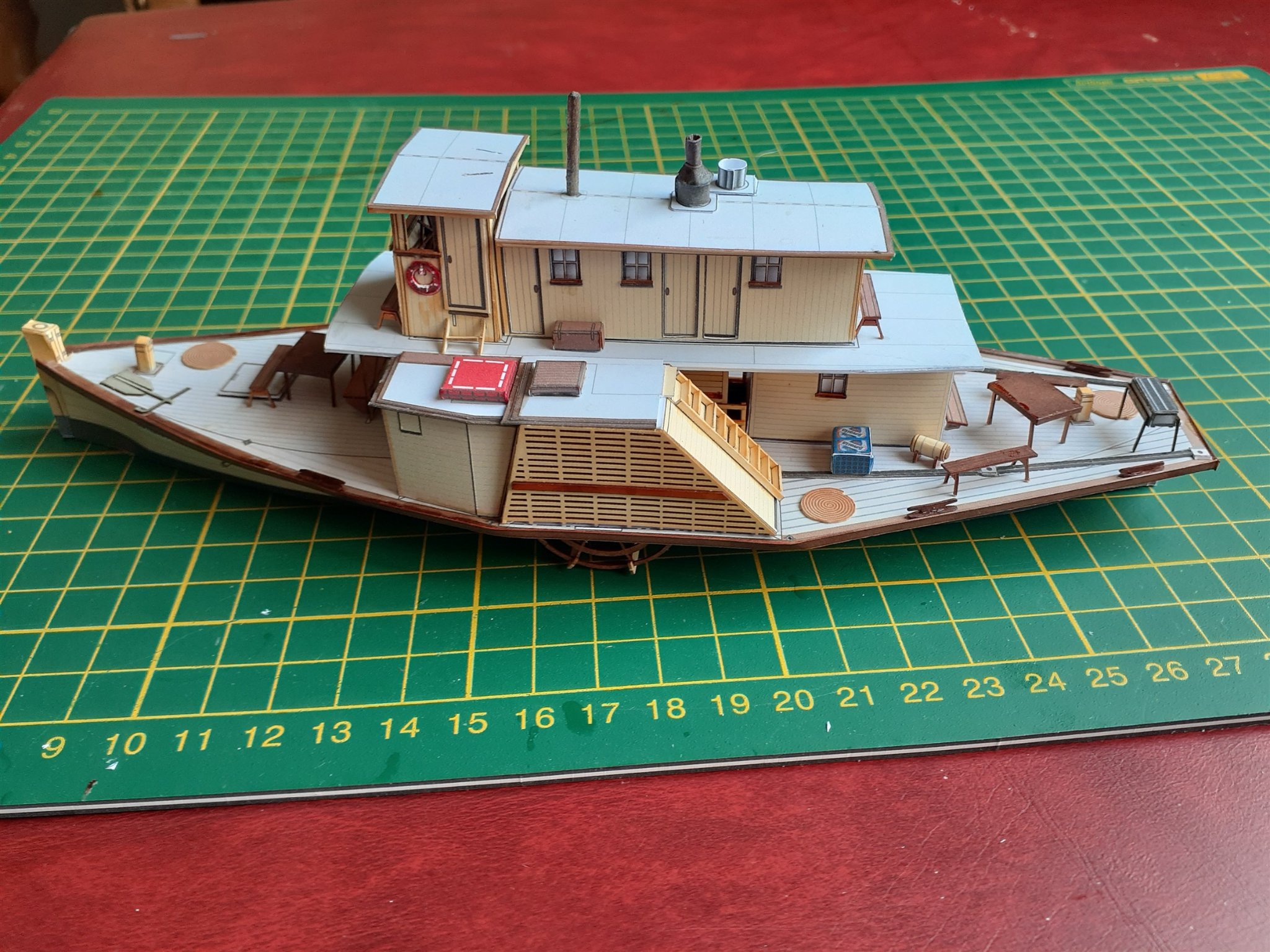
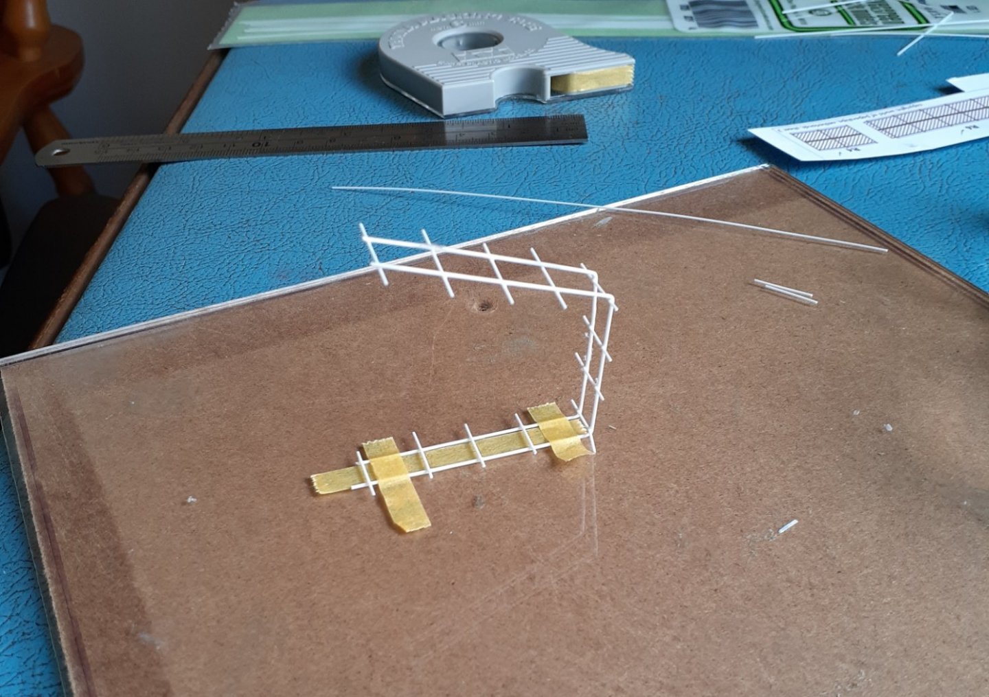
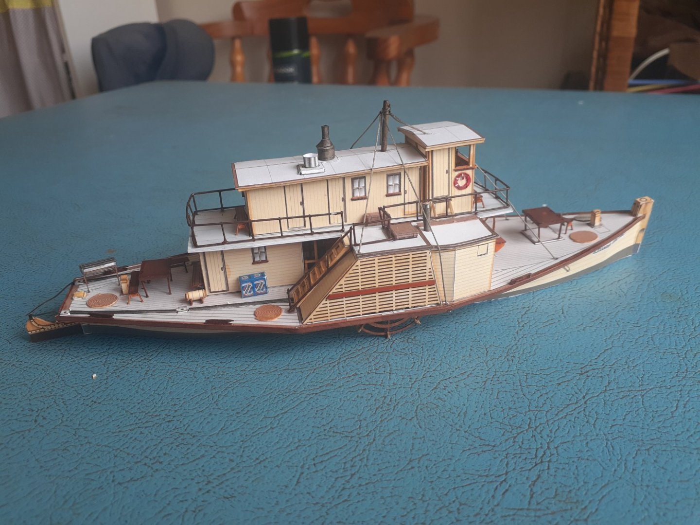
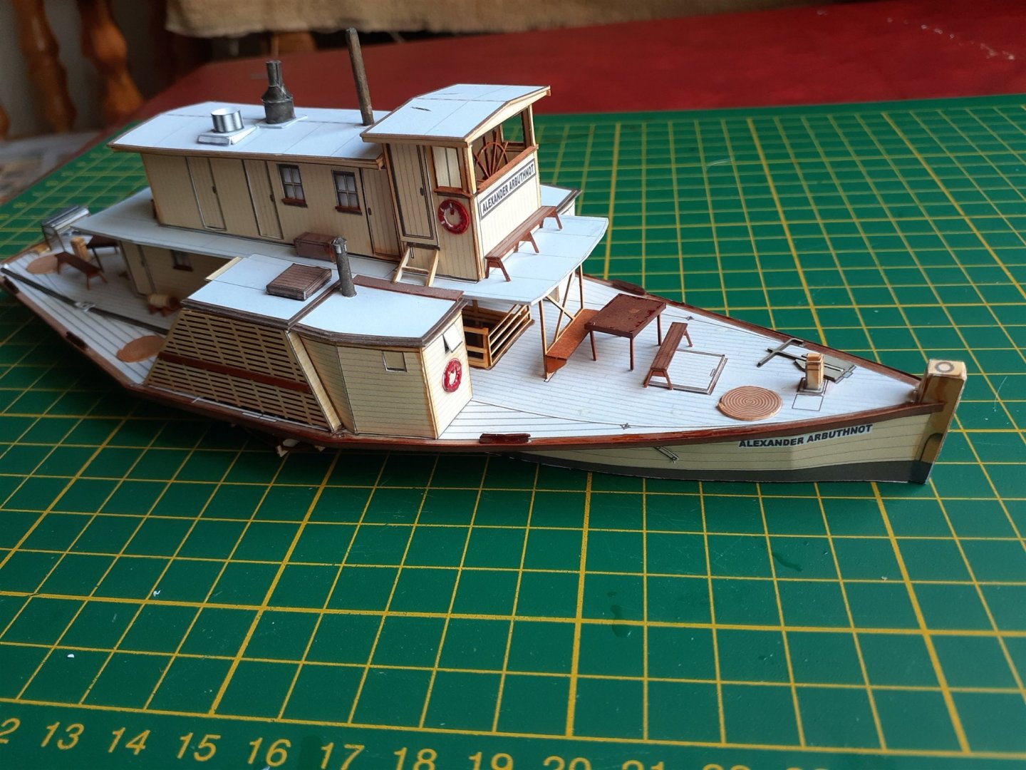
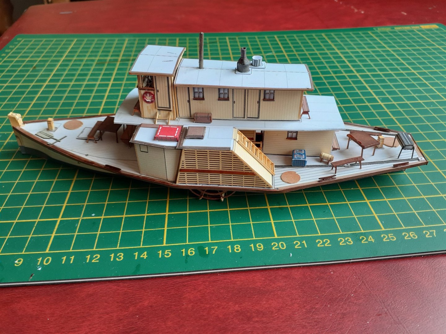
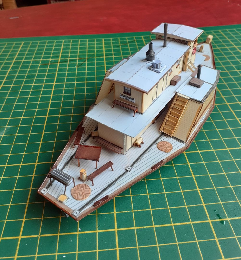
Thanks for the likes. After a break of some weeks, I've managed to get back to AlexA, and complete the build. The railings around the upper deck were done first. There are ten sections of printed railing but only six laser-cut sections. So my choices were to go with the printed ones, mix the printed and laser-cut or scratch build new ones. I didn't particularly like the printed ones, the mix would have looked odd, so I went with scratch built. I used styrene rod, 0.64mm for the horizontals and 0.50mm for the uprights. This photo shows one of the rail sections being made. This piece goes onto the forward part of the deck, and the kit has it in three sections. I have carefully bent the rod so that I have one wrap-around section instead of three. I did the same for the aft railing. All railing sections were then glued in place. Several of the verticals were kept long enough below the bottom rail to locate in holes very carefully drilled (with a pin vise) in the deck. The rudder was glued and the steering chains, which lie along the deck, were extended to the aft edge of the rudder. The minor amount of rigging was done and finally, the tables, seats, BBQ etc were glued in place. The finished Alexander Arbuthnot. Cheers


- 18 replies
-
- 8
-
-
-
- card
- World of Paperships
- (and 2 more)
-
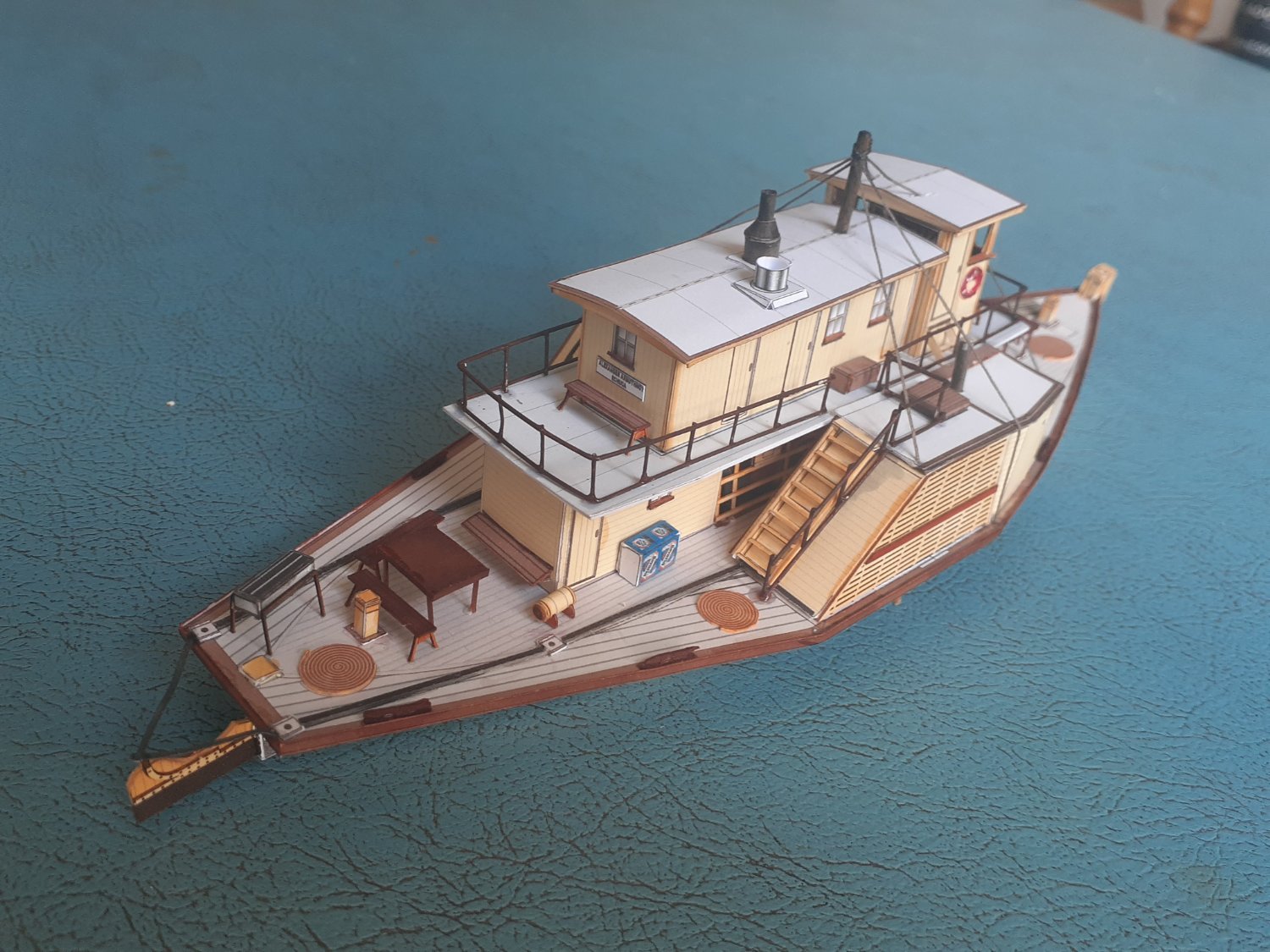
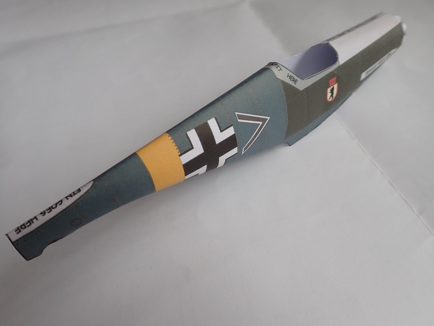
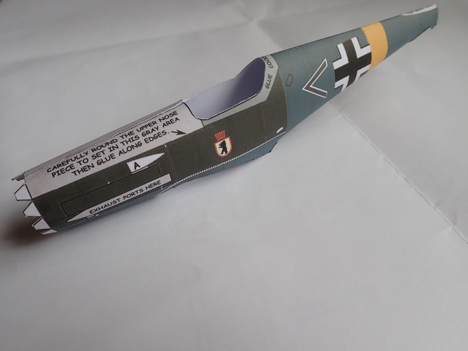
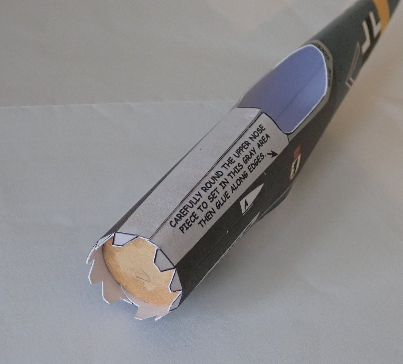
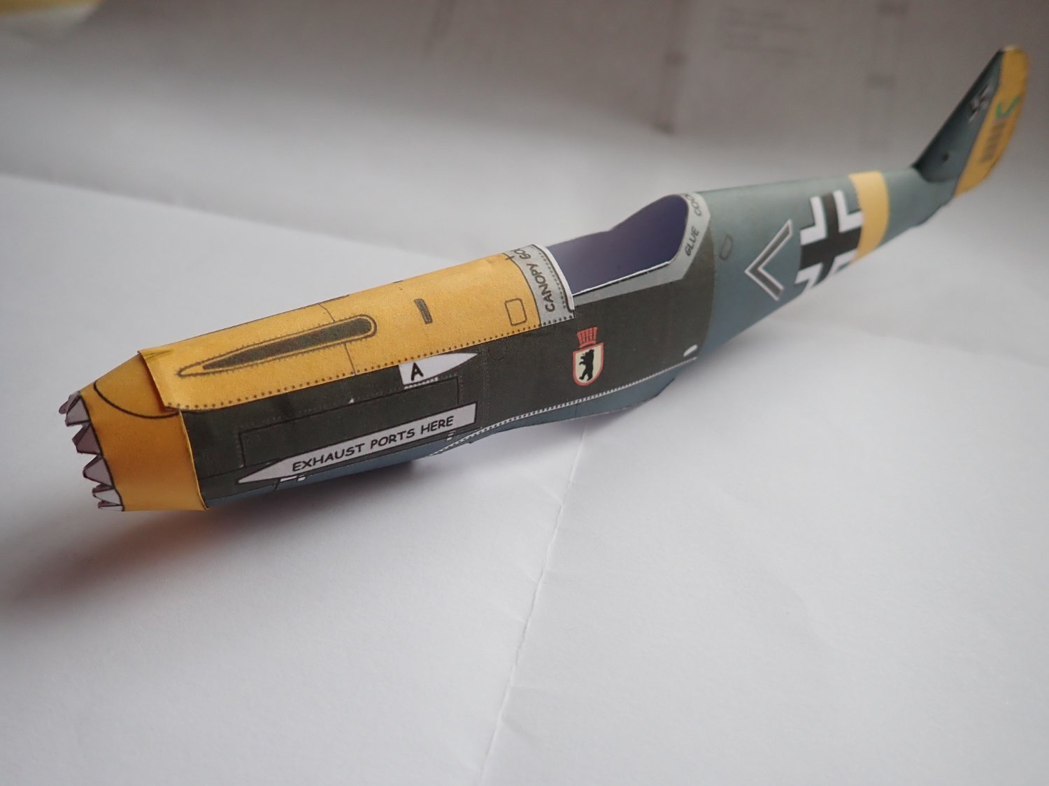
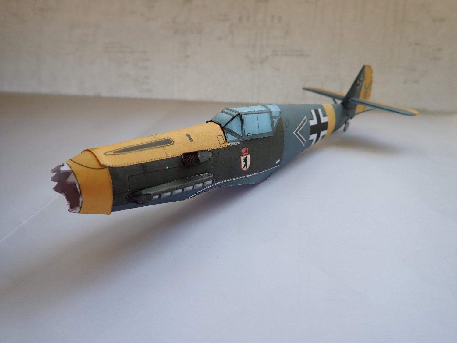
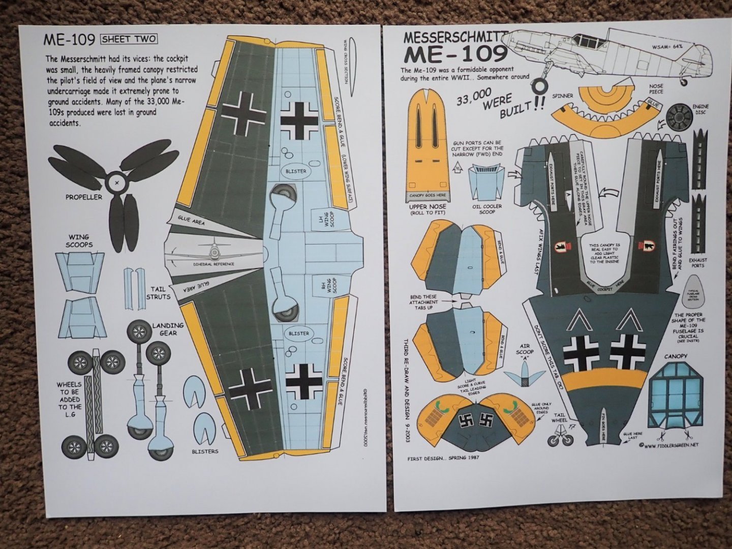
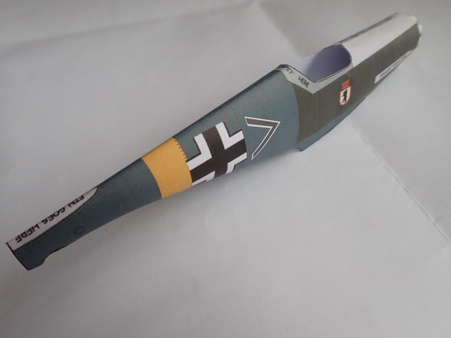
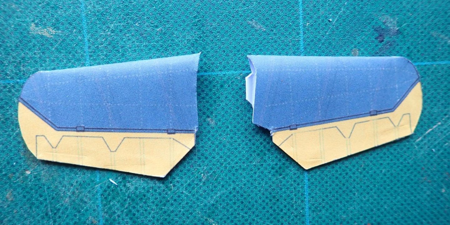
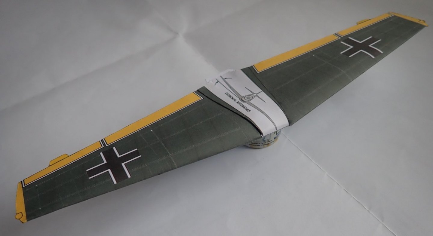
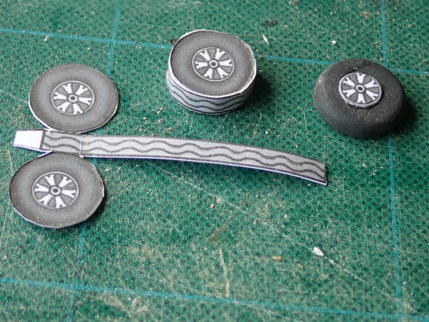
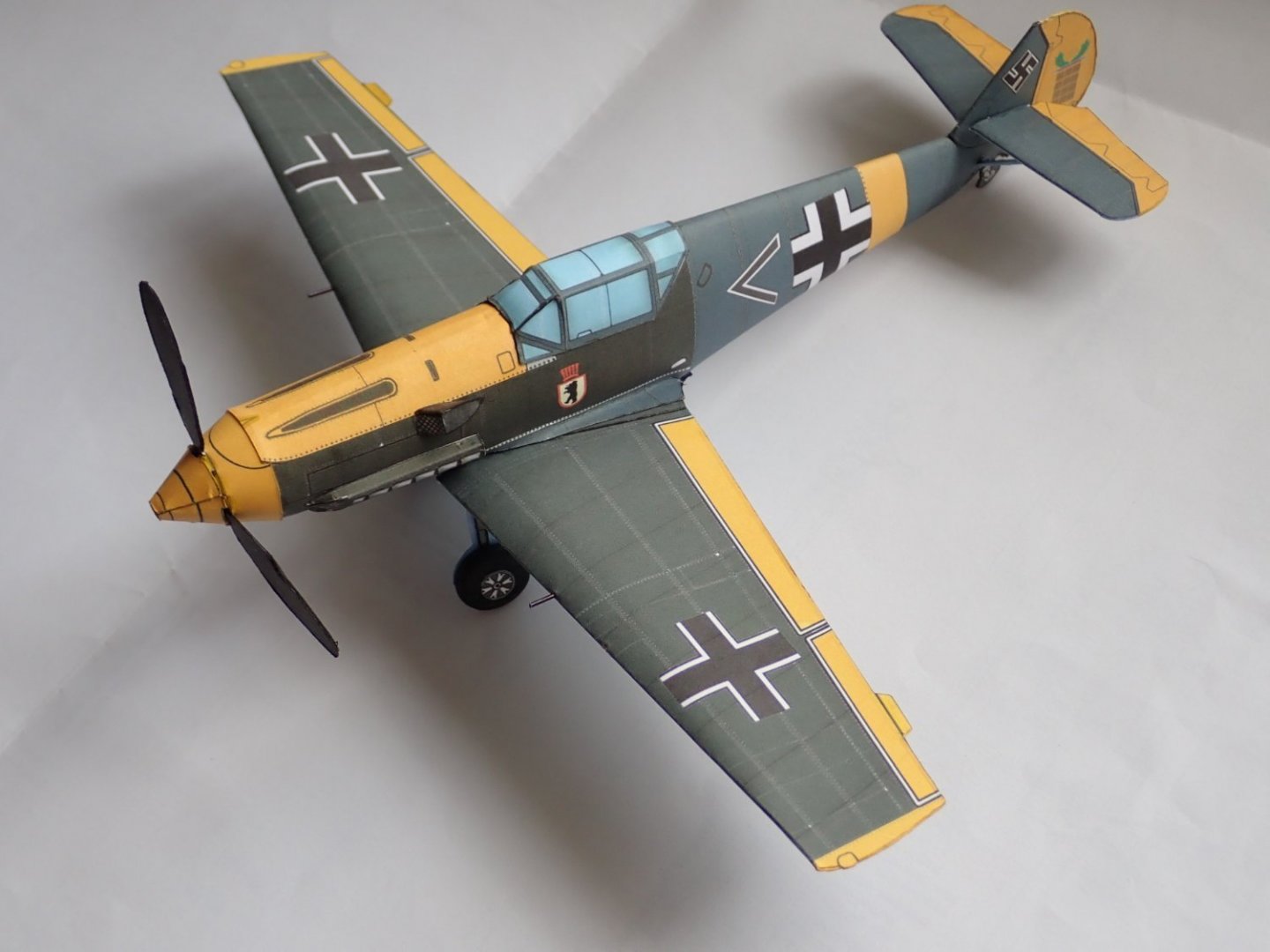
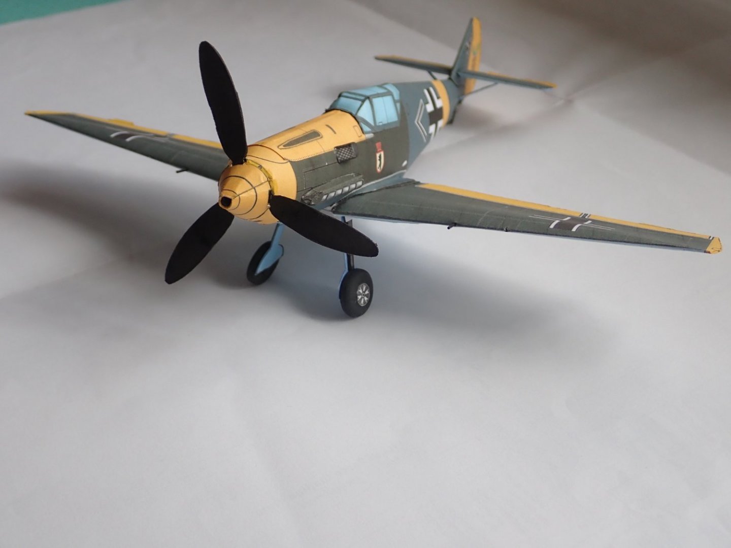
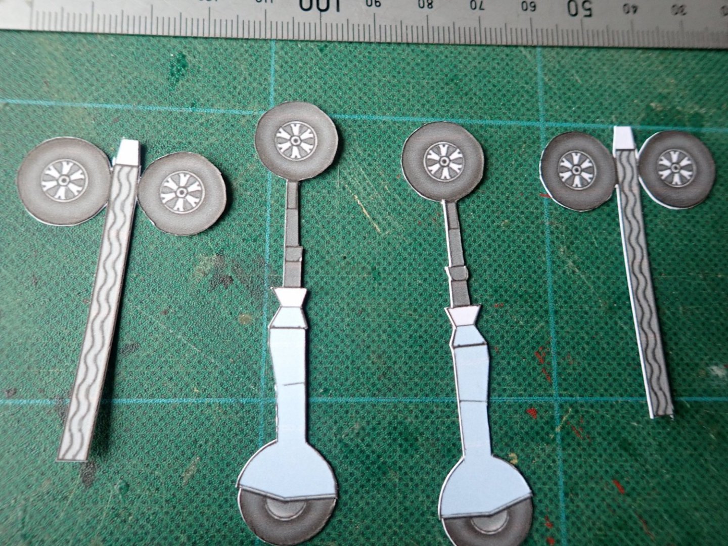
I decided that I'd like to try building a card aeroplane model. Certainly not one as complex as a Halinski kit, so I searched and found that Fiddlers Green allowed you three free models (to download) if you signed up, in the hope you would buy models in the future. One of the kits I chose was the Me109. This kit comprises just two A4 sheets with a total of 25 parts, there are no laser-cut pieces, no fuselage formers and no wing spars or ribs. Instructions are minimal. This build log will perhaps be the shortest one on MSW. The two sheets of parts. The basic fuselage assembled. The forward fuselage is circular in section, so I added a former (scrap wood) to make it easier to attach the cowling and spinner. The top deck, cowling and fin/rudder have been added. I have punched a hole through the fin to allow a short length of dowel to be used as a supporting spar for the tailplane as the kit simply has this glued to the fin with a short tab. This did not seem especially secure to me. And there was a problem with the tailplane anyway, which I'll come to in a minute. The two halves of the tailplane. The starboard one is as printed and cut out. The problem here is that there would be a large gap between the fin and the inboard end of the elevator, if assembled as per kit. The inboard end of the tailplane needs to be trimmed, and the port half has had this done. The mounting tab that is visible on the untouched starboard half vanishes as a result of the surgery, making the spar mentioned above even more essential. The tailplane (plus struts), tailwheel and canopy have been added. Also the exhaust stacks and the air filter on the side of the fuselage. The front of the cowling has been butchered slightly to allow for the fixing of the propeller. The wing, fairly simple, one piece folded along the leading edge. And now for the undercarriage. As cut out. The wheel, hub plus tyre, is supposedly to be made by wrapping a length of card patterned to represent the tyre tread around two discs that are the hub/tyre. This and my attempt at doing this are shown below, though to be fair I didn't put much effort into doing this as I couldn't imagine the end result being anything like an aircraft wheel. So, I made two tyres from scrap wood and glued hubs to these to give a reasonable representation of the wheels, as shown on the right. The undercarriage legs were strengthened with strips of wood. The fuselage and wing were joined together quite easily. Wing radiators, airscoop under the nose, wing guns (short lengths of styrene rod), the propeller and spinner were then fixed. Finally, the undercarriage. This was somewhat awkward as the kit made no provision for mounting this. Some scrap card was used to support the legs and to get, as near as I could, the correct angles. Seems to have worked. There are some problems with the kit, but as it was free, I cannot complain. Interestingly, there is a notation on the bottom of one of the sheets that says "First design Spring 1987" and "Third redraw and design 9-2003". Slightly frustrating at times, but a good introduction to a card model.


-
Thanks for the likes. Almost finished. The tables, bench seats, BBQ (on the rear deck) etc, have been placed on the boat for the photos but are not yet glued down. The upper deck railings will be the last major thing to be done. The rudder is not yet in place either. And there is some rigging to be added. Cheers
- 18 replies
-
- 8
-
-
- card
- World of Paperships
- (and 2 more)
-
Intro to Card Models Pt. V: Building V108 - The Hull
Richard44 replied to ccoyle's topic in Card and Paper Models
Chris, I understand that doing this gives the sheets, ie parts, protection, but how about gluing? There will be places where glue has to adhere to an area that has been treated, so do you swap from using PVA (I assume this is your usual glue) to another type of glue, eg CA? My apologies if you have answered this elsewhere. Thanks- 25 replies
-
- 2
-
-
- card models
- paper models
- (and 1 more)
-
Chris, I've looked at the Halinski website several times, and nowhere can I find any info about a particular kit other than what I assume is the cover photo. Am I missing something? Cheers
-
Thanks John. Not much more to do now. Small items, including a BBQ and a carton of beer!
- 18 replies
-
- 1
-
-
- card
- World of Paperships
- (and 2 more)


.JPG.18f5eb09d819a129174bcf5576742871.JPG)