HOLIDAY DONATION DRIVE - SUPPORT MSW - DO YOUR PART TO KEEP THIS GREAT FORUM GOING! (89 donations so far out of 49,000 members - C'mon guys!)
×


Richard44
-
Posts
429 -
Joined
-
Last visited
Content Type
Profiles
Forums
Gallery
Events
Everything posted by Richard44
-
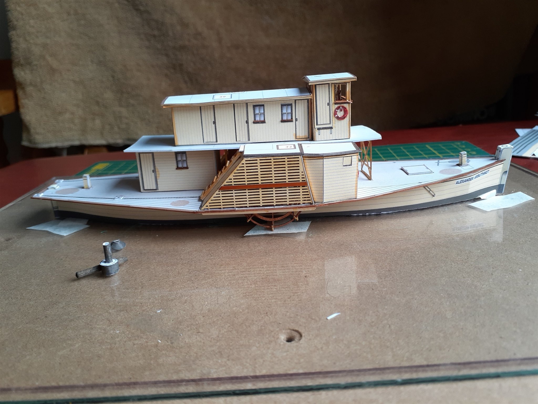
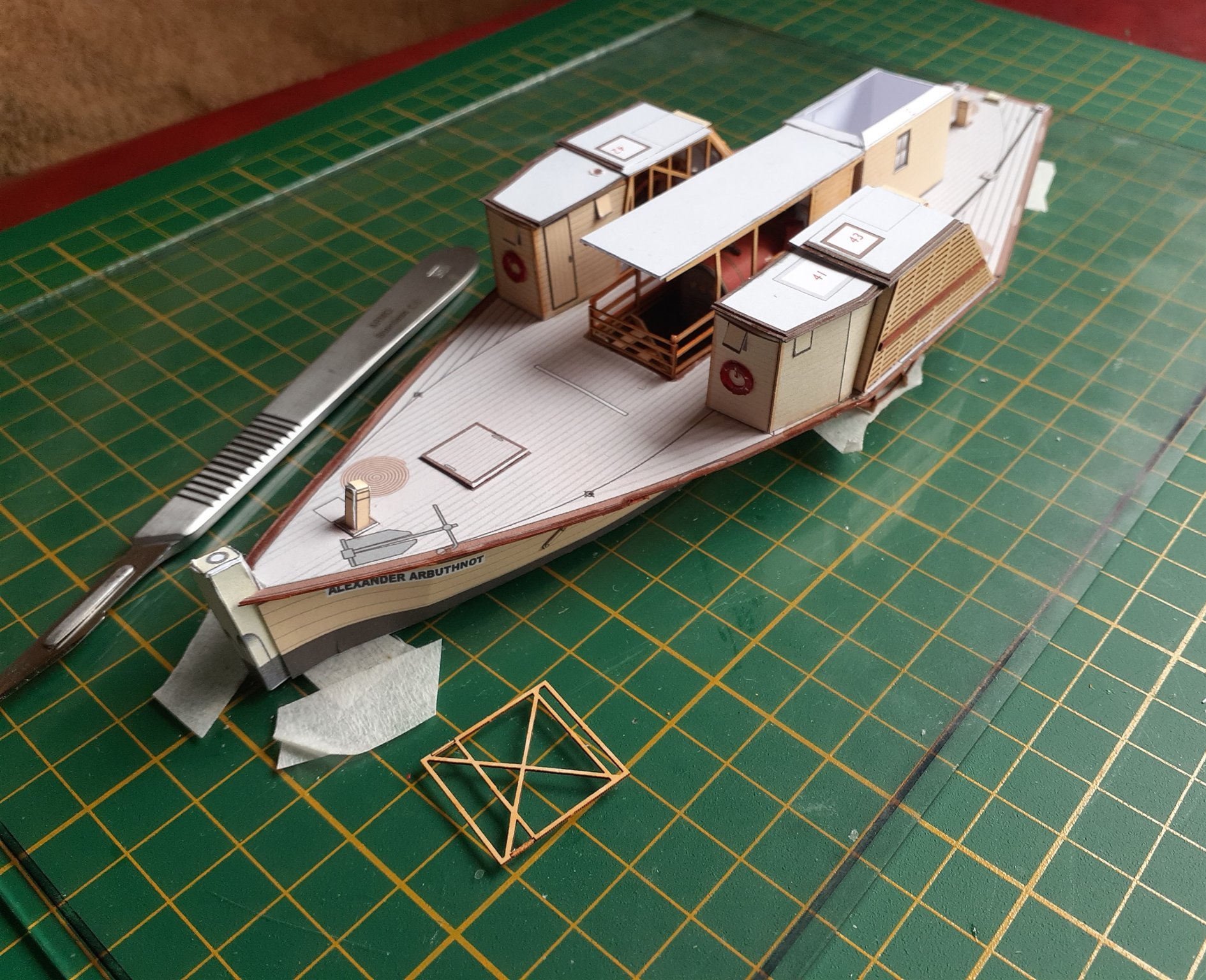
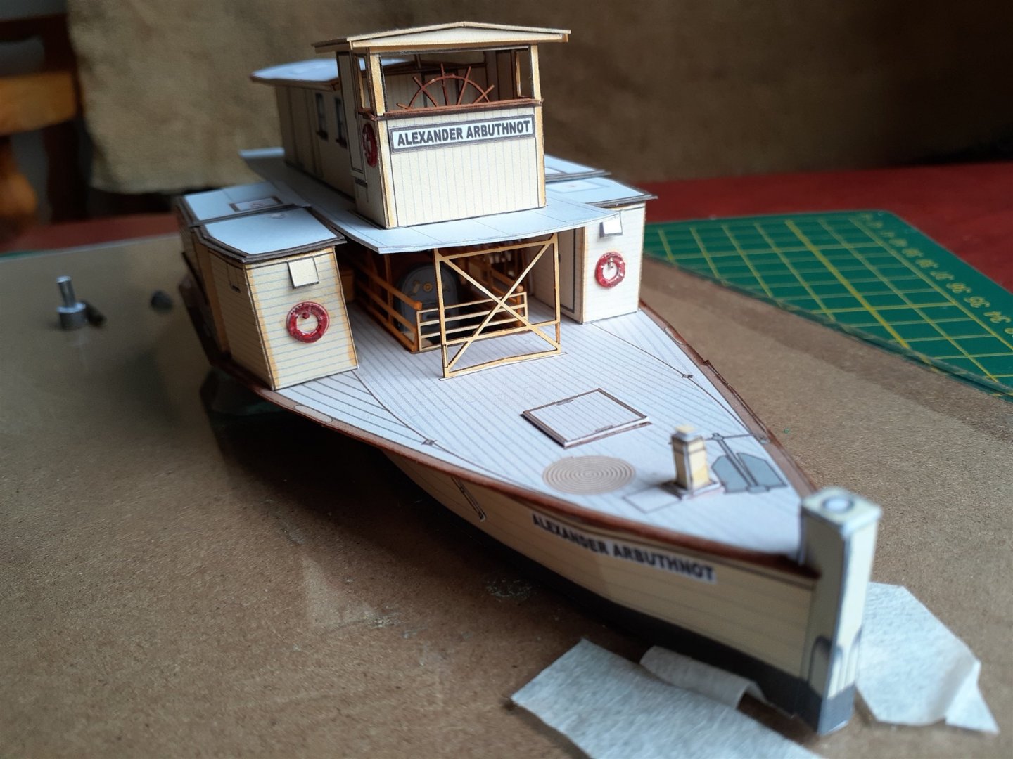
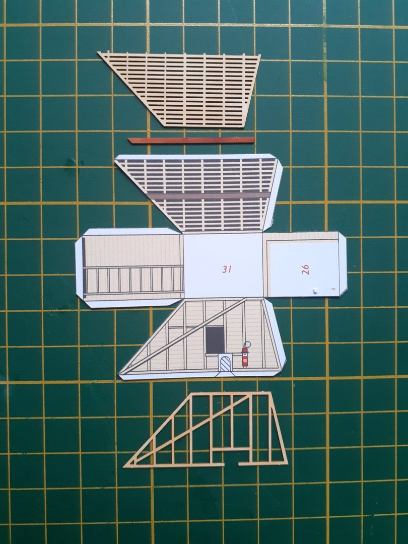
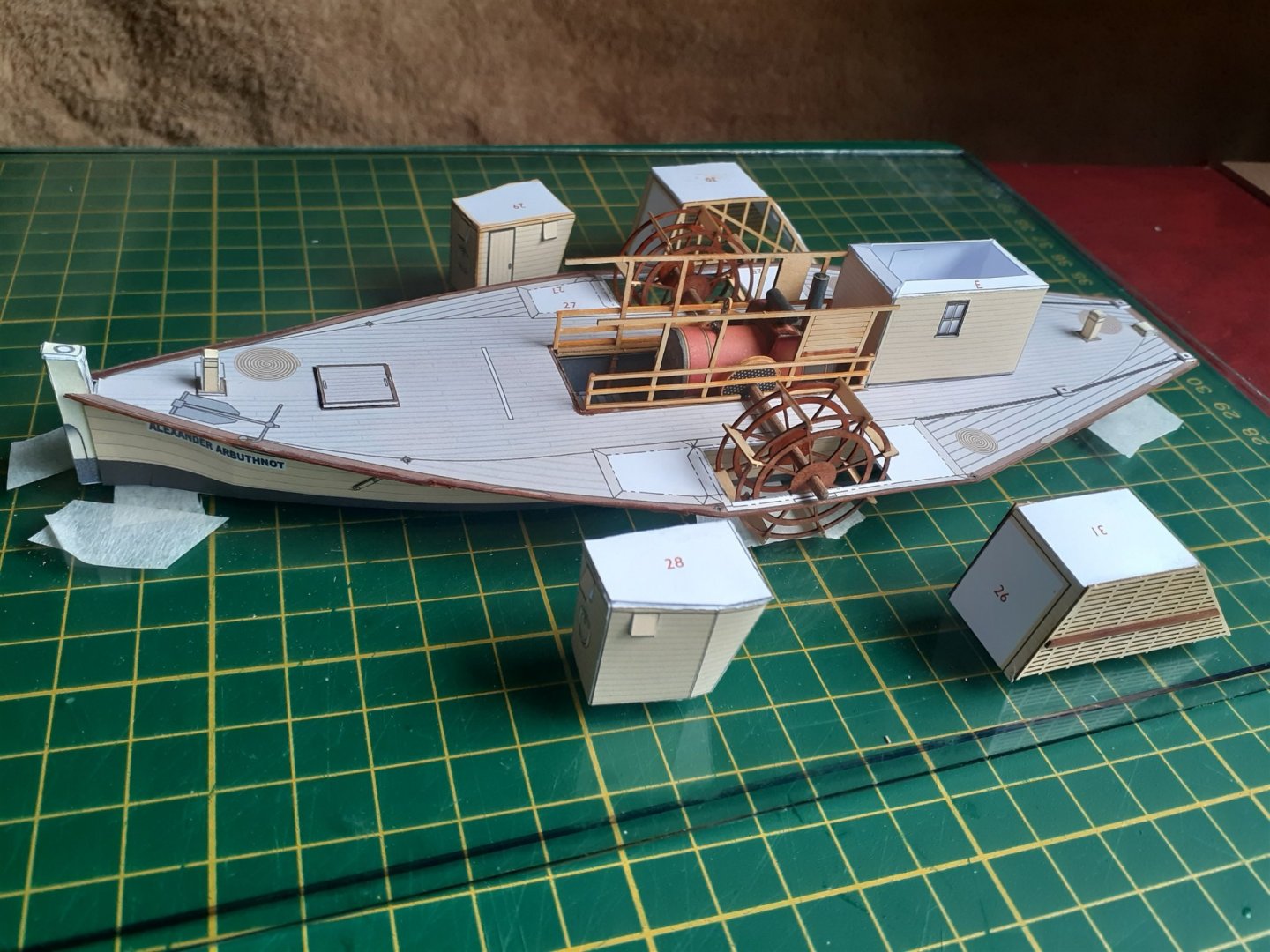
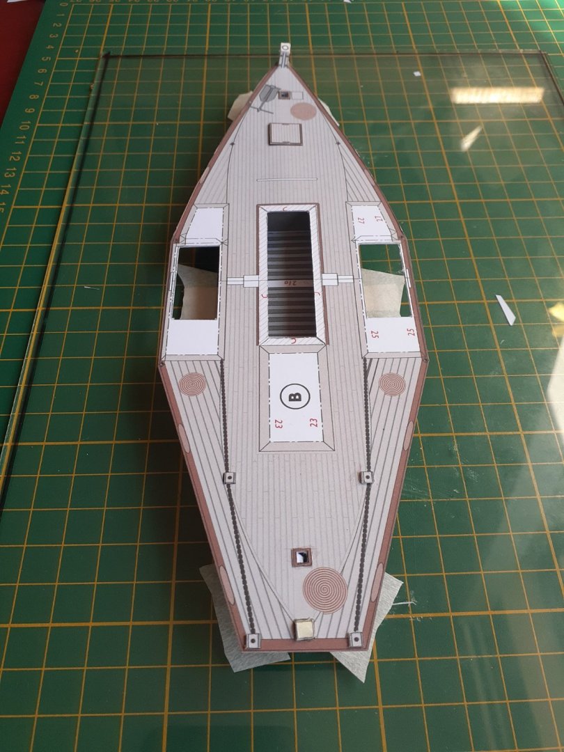
 Thanks for the comment and the likes. The upper deck cabins, the wheelhouse and the wheel, the latter from lasercut board, all ready for fixing in place. The hull with the completed superstructure. Cheers
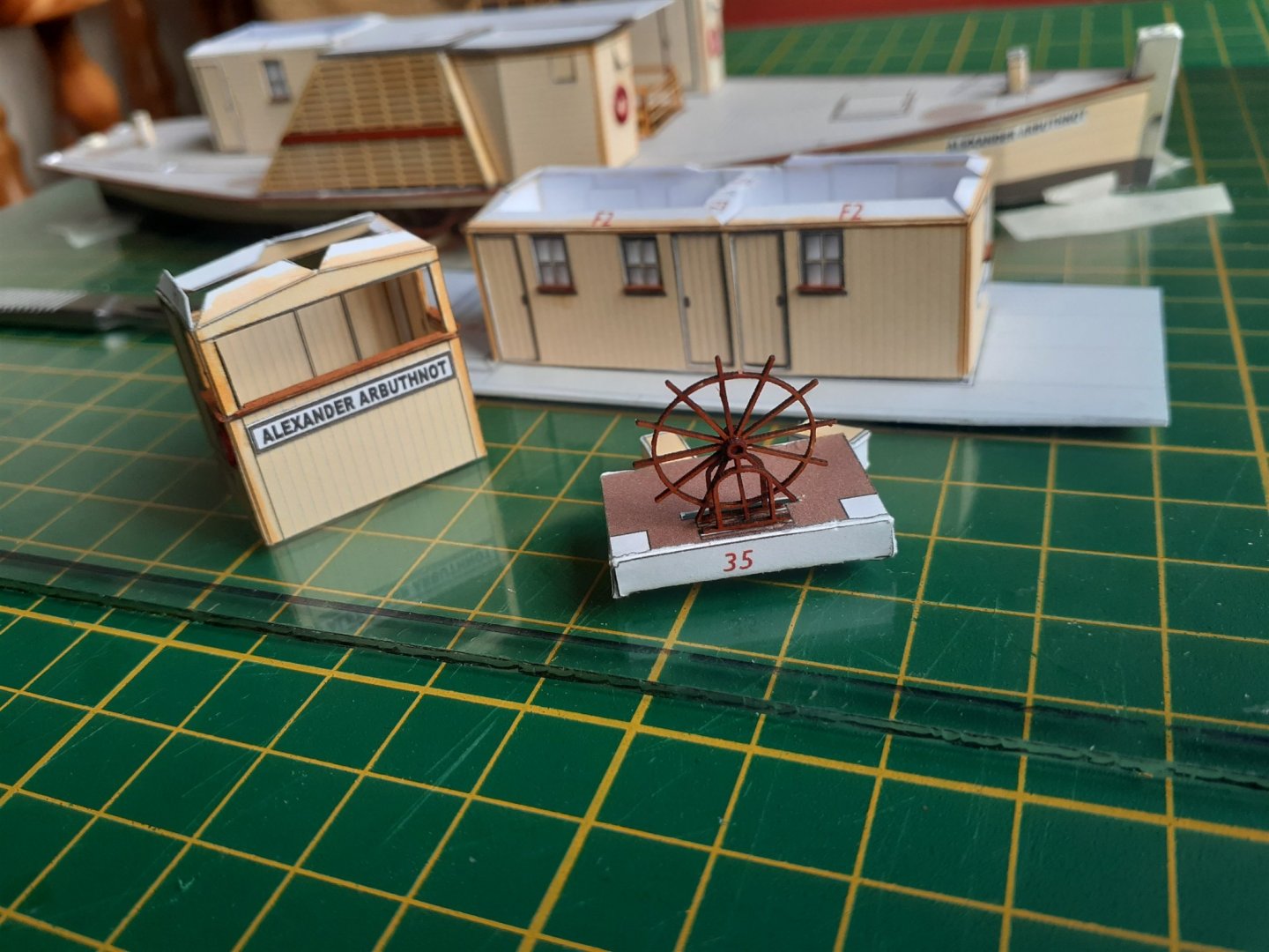

- 18 replies
-
- 7
-

-
- card
- World of Paperships
- (and 2 more)
-
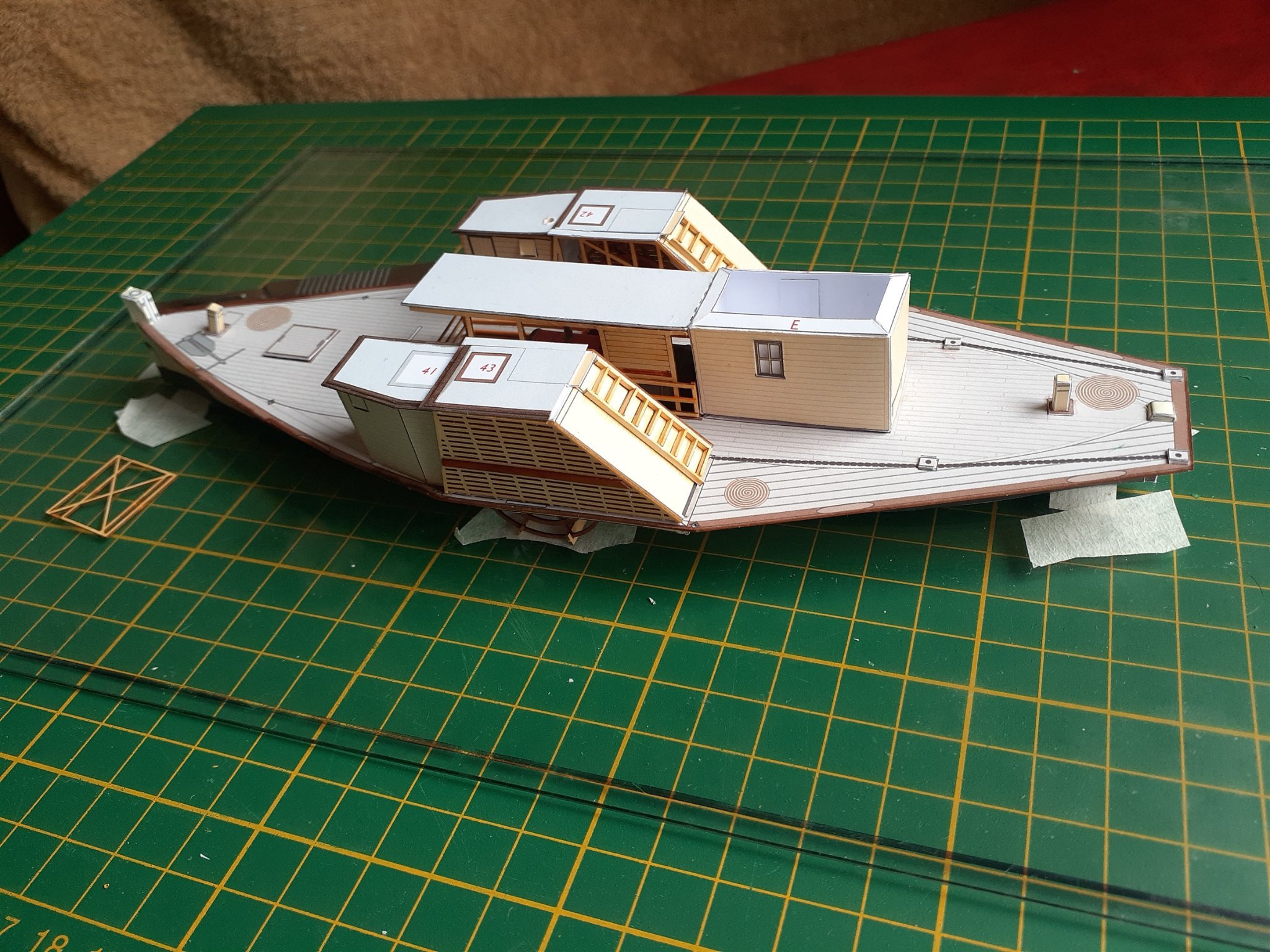
Thanks for the likes and the comments. One of the paddlewheel boxes as cut from the printed sheet, and the two lasercut replacements for the sides. The completed boxes and the forward side gallery ready to be added to the hull. The paddlewheels are in position but not fixed yet. The lasercut framing around the engine bay has been glued in place. The framing around the bay has been completed, the paddlewheels fixed in place, and the boxes, gallery and roof over the engine bay have all been added to the hull. The ladders on the aft of the boxes were made in place using the provided thin strips of printed card. This was one of the jobs where the quick grab of the PVA made this fairly easy. Cheers


- 18 replies
-
- 6
-
-
- card
- World of Paperships
- (and 2 more)
-
Hi Greg, As others have said, welcome to MSW. I'll be watching your build of the Pevensey with great interest as I have just ordered a 1:100 card model of it from World of Paperships. Cheers
-
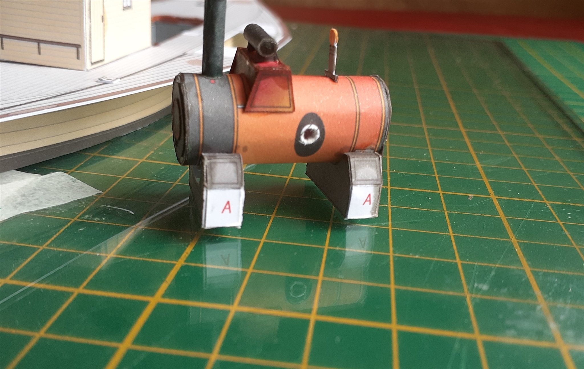
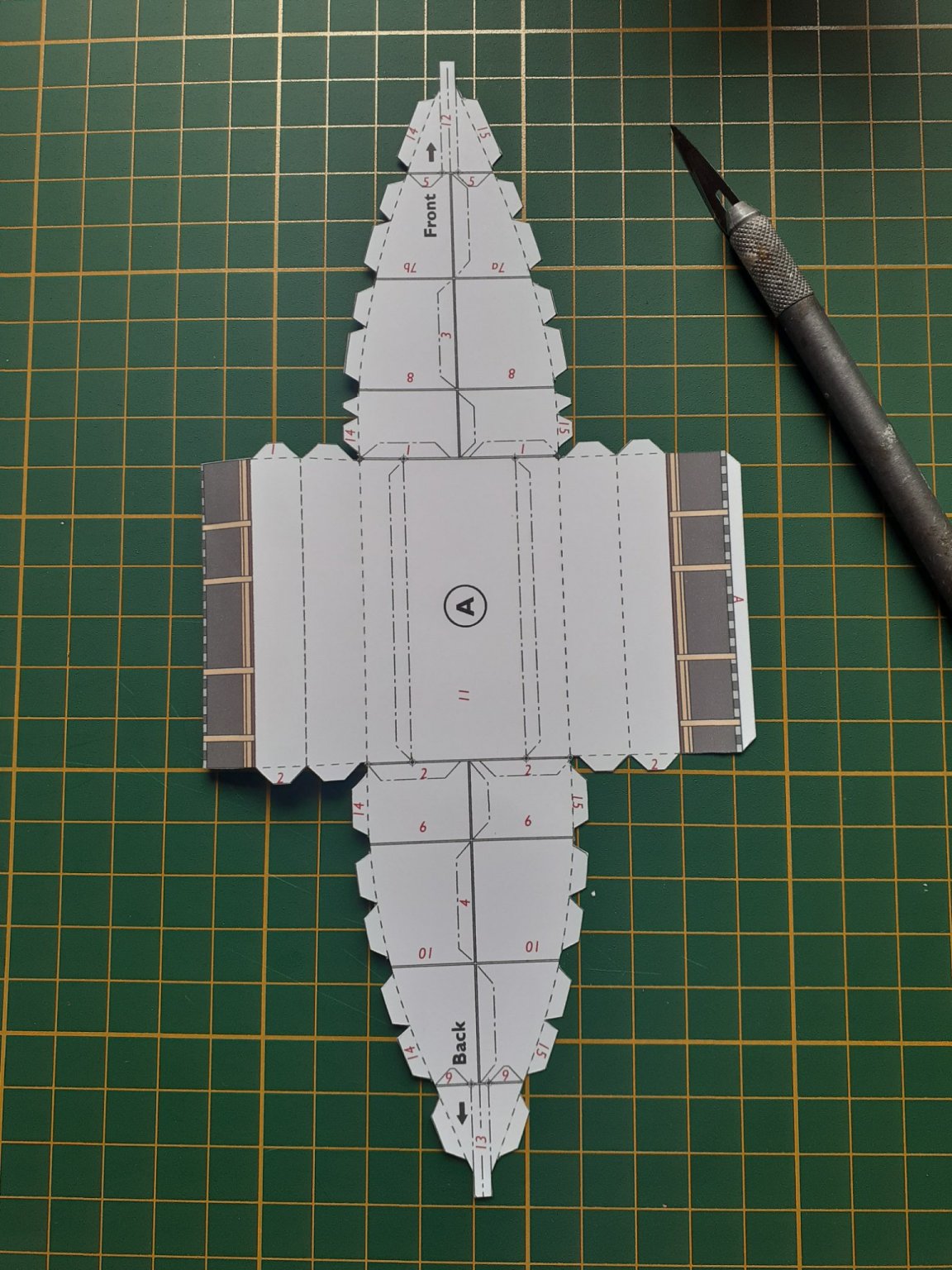
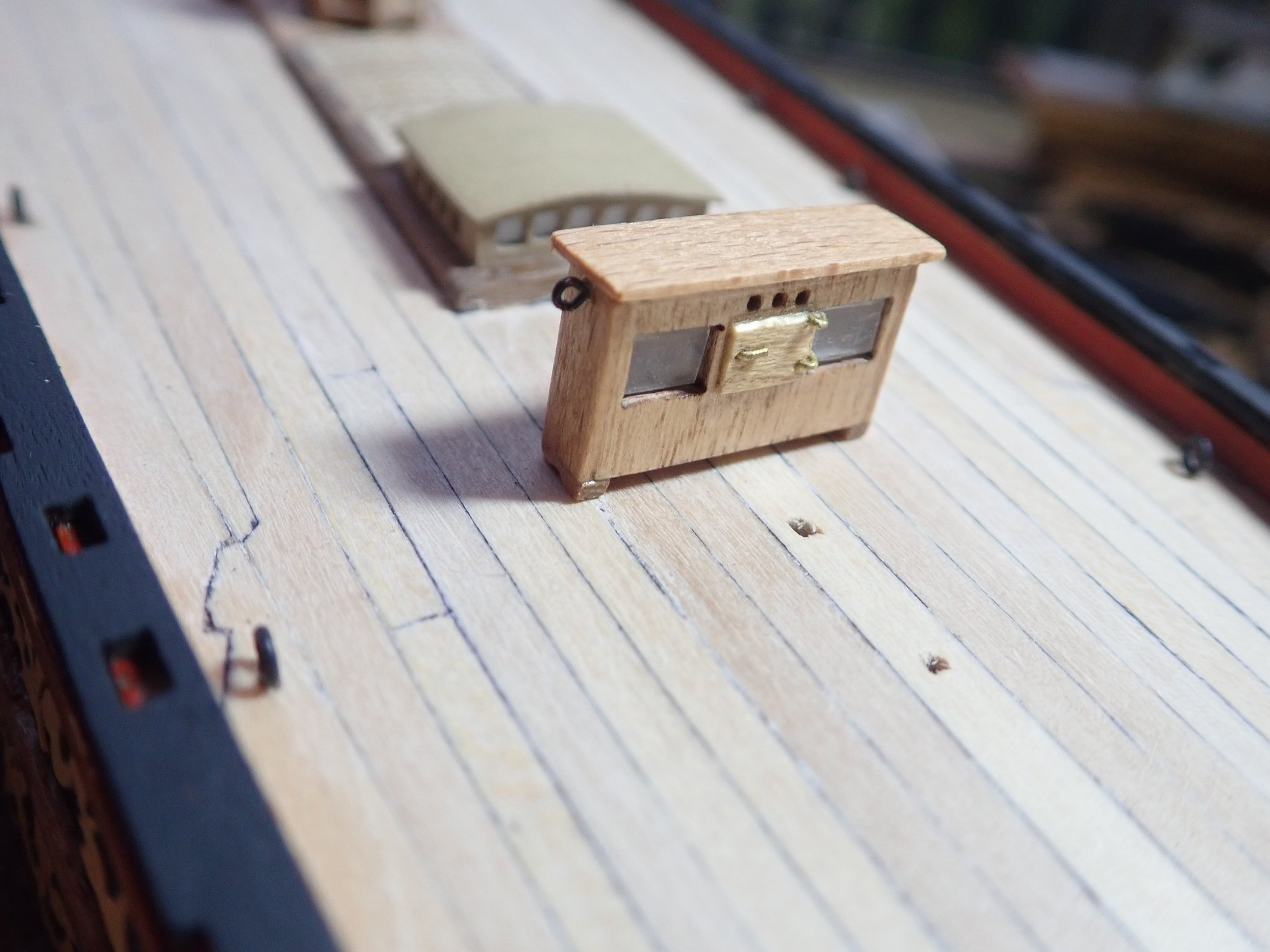
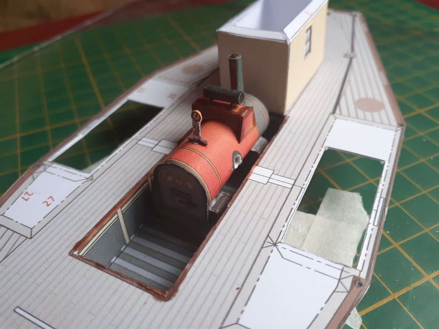
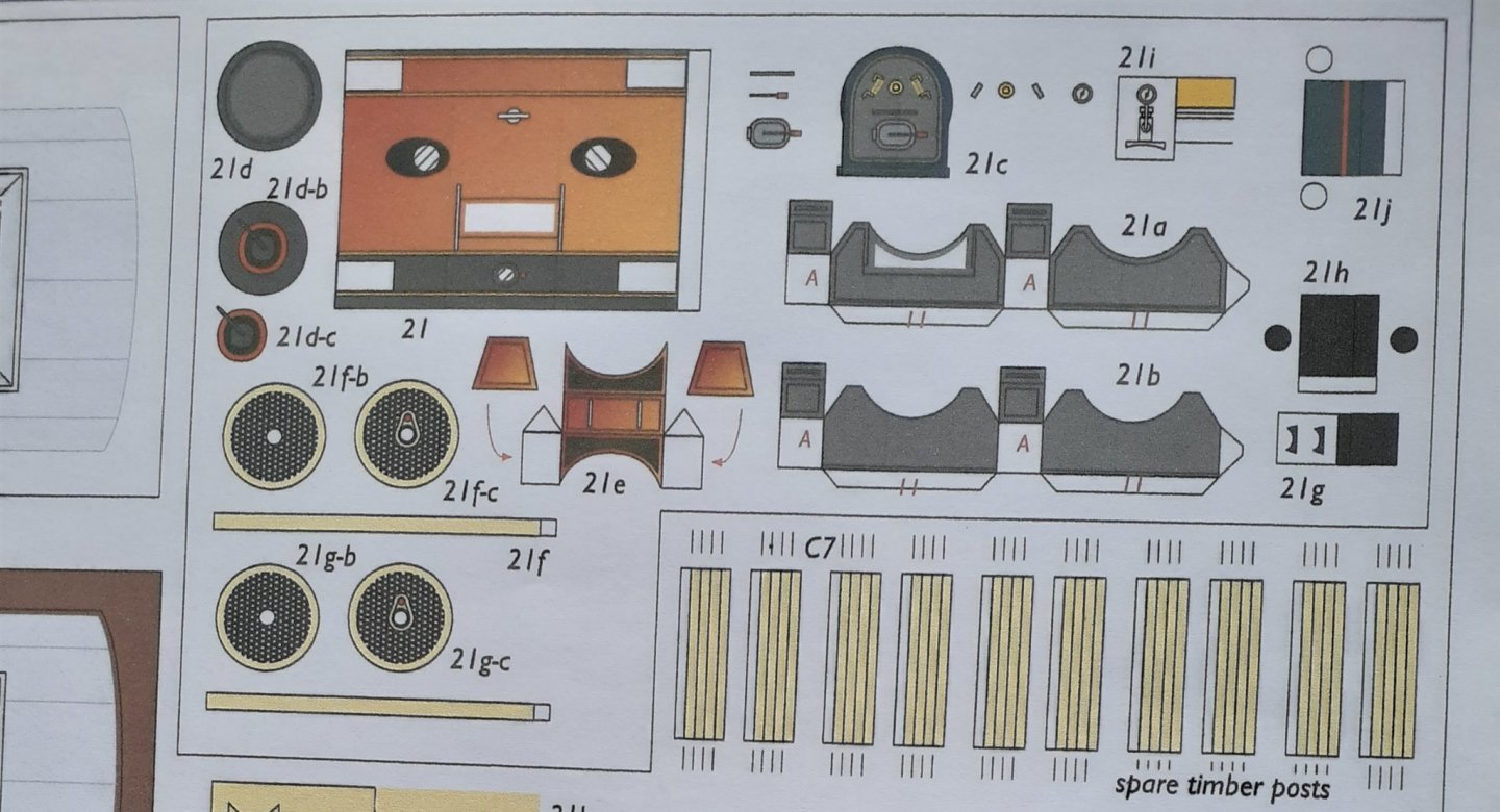
Thanks for the likes and the comments. The next job was to build the boiler. The kit actually says the boat can be built in a simplified form if you want to, and the boiler is one of those parts that can be omitted. I decided to build the boiler, even though when AlexA is completed it'll be barely visible. (As an aside, I edge coloured parts using some artists felt-tipped pens I already had that were reasonable matches for the printed colours.) The parts for the boiler are contained within an outlined box on one of the sheets. The completed boiler. The hole in the side is for the shaft for the paddlewheels, though this is certainly not how it actually was. Not all parts of the actual engine are provided, in particular the cylinders/pistons that would have driven the paddlewheels are missing, but they wouldn't be visible in the model anyway. The boiler in place. Cheers

- 18 replies
-
- 7
-
-
- card
- World of Paperships
- (and 2 more)
-
Hi John, Thanks for the comment. World of Paperships (a Dutch company) has two other Echuca paddlers - Adelaide and Pevensey. He also has six models of Sydney Harbour ferries! Cheers
- 18 replies
-
- 4
-
-
- card
- World of Paperships
- (and 2 more)
-
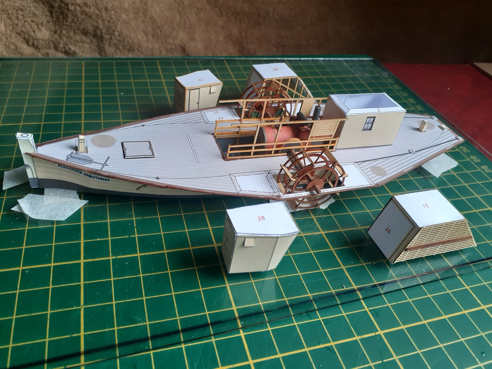
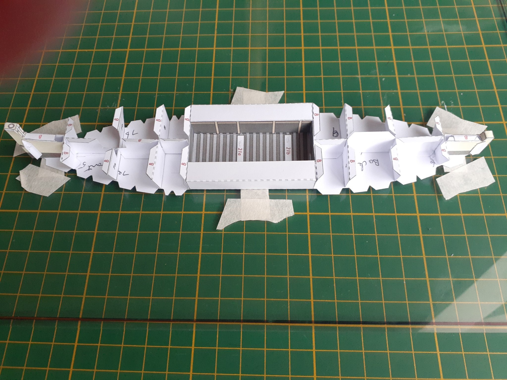
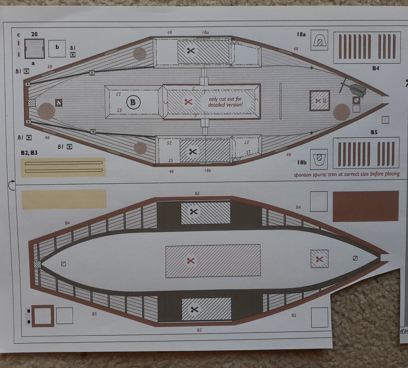
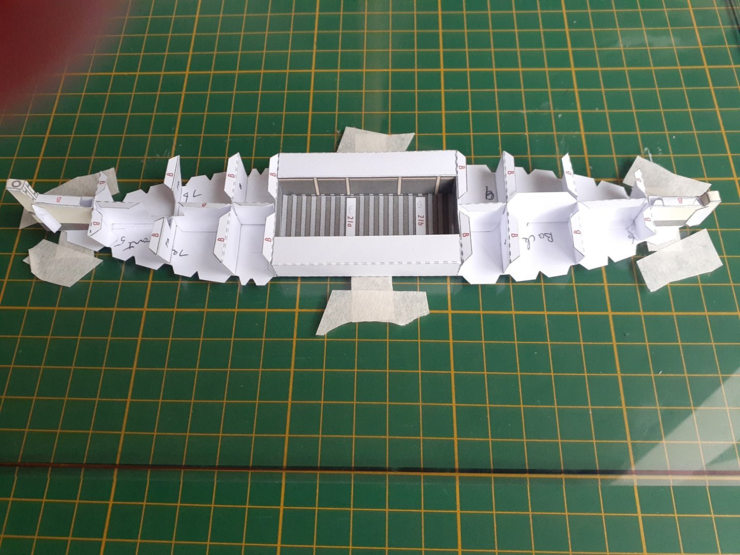
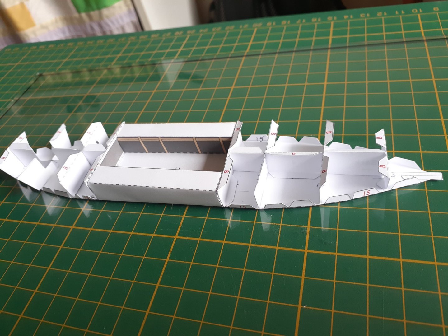
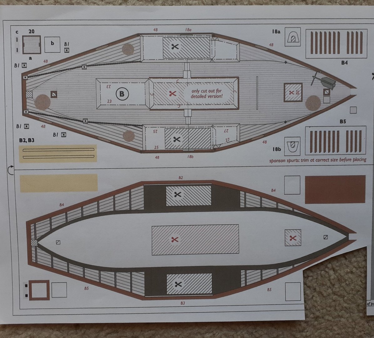
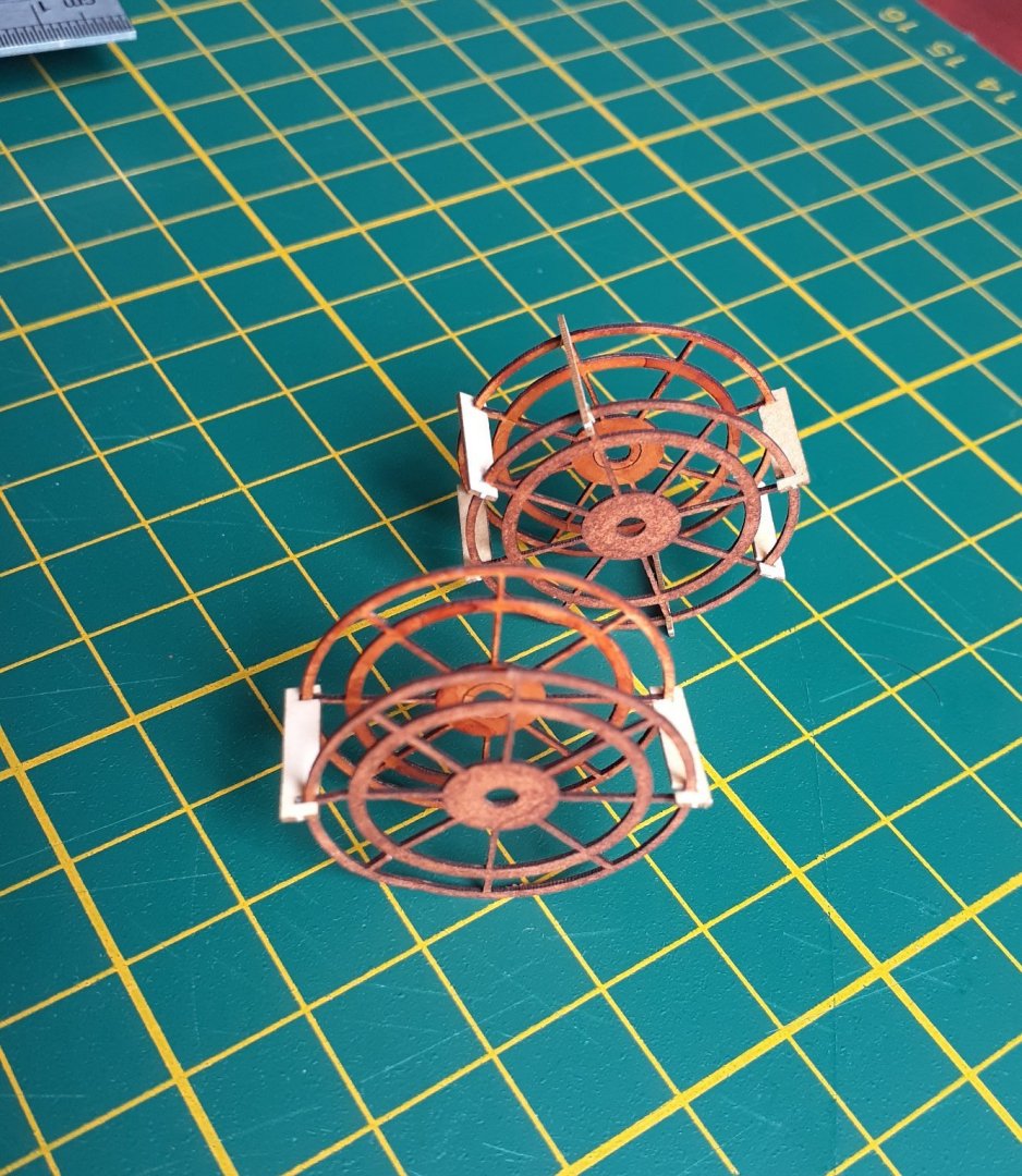
My first card model of a boat. I'm spending time between two homes, and Pegasus is too awkward to shuffle from home to home, so I needed a model to build at home2. A card model is highly suitable as it is compact, needs only a few hand tools, doesn't need painting other than touching up edges and is almost mess free. Chris Coyle's descriptions of his card models and his tutorial on building the torpedo boat, tipped me over the edge into what he has called the abyss. 🥴 So, what model. I certainly didn't want a complicated one to start with, the torpedo boat was tempting, but while browsing various websites I came across one that grabbed my interest. It is a 1:100 scale model of a Murray River (Australia) paddlewheeler - the Alexander Arbuthnot. This boat was built in 1923 and worked towing barges laden with logs to the Kroondrook sawmill on the Murray River. The mill was owned by Alex A himself after whom the boat was named. The boat worked until the 1940s but then fell into disrepair and sank. It was later raised and restored and now operates day cruises from Echuca on the Murray. The kit is one published by "World of Paperships", and comprises six printed sheets, one sheet of optional laser cut parts, five pages of instructions, one page of diagrams and one page of general info about the vessel. The designer's advice of scanning (or copying) the six printed sheets to provide backup in case of mistakes was followed. Photos of the build are sporadic as I often forgot to take them. The hull bottom was cut out, folded and the bulkheads glued in place. My first experience with using PVA on a card model. Interesting. The big advantage of using PVA was its quick grab time, just holding parts together with fingers for a minute or so was sufficient. The big disadvantage of using PVA was its quick grab time, the chances of repositioning anything is essentially zero. And so to my first mistake. Some of the bulkheads were very, very slightly mispositioned. This became apparent when I started to glue on the hull sides. Not normally a problem with a wooden model, but almost impossible to correct with a card model. So, out with the backup copies and start again. The second attempt. The hull bottom with the correctly placed bulkheads and held down on a sheet of glass by thin masking tape. The designer recommends to do this to keep the hull from warping in the early stages of construction, though he suggests paste not masking tape. The main deck, shown here on the sheet, was doubled and glued to the hull. The paddlewheels were constructed using the parts from the laser-cut sheet. The hull with part of the superstructure, the two paddlewheels and the supports for the boiler. The image is upside down, and I have no idea why. 😬 Cheers

- 18 replies
-
- 8
-
-
- card
- World of Paperships
- (and 2 more)
-
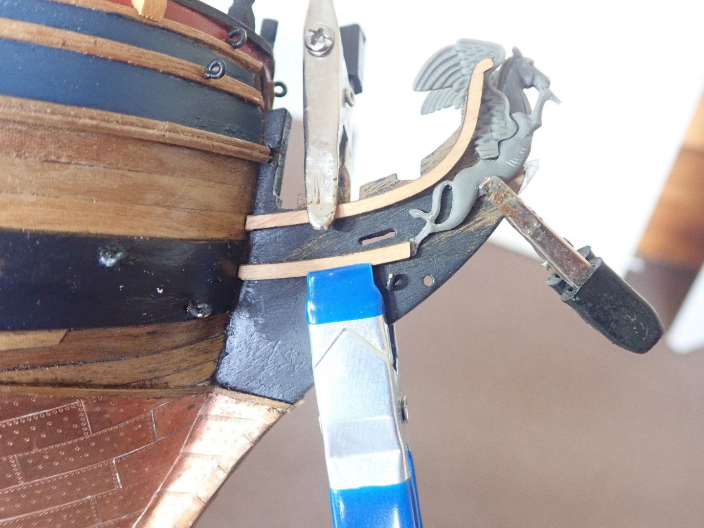
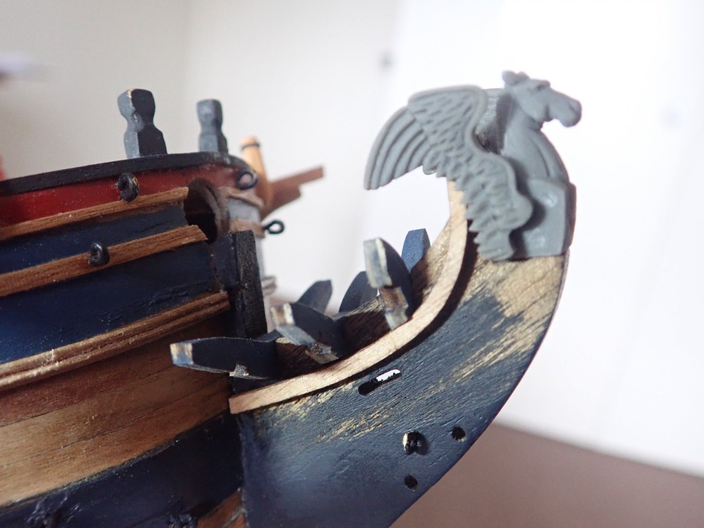
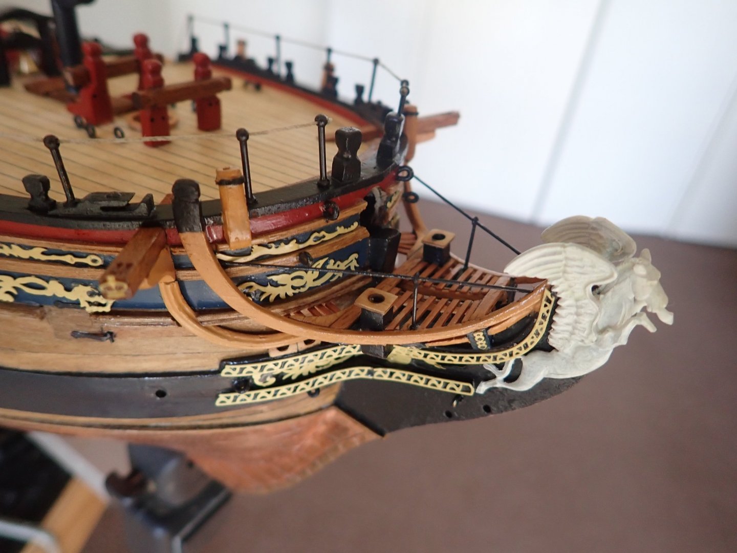
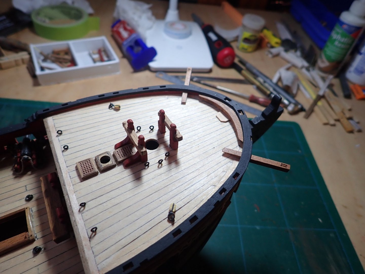
Onto the headworks, where I immediately ran into a problem. With the figurehead in place, there was insufficient clearance for the upper prow rails (part 127) to fit between it and the prow. If I moved the figurehead forwards to provide the clearance, it protruded past the prow by a couple of mm. I therefore thinned the prow so that the total width of the prow plus the two upper rails was 5mm, the original width of the prow. Construction of the headworks then more-or-less followed the plan/instructions. The head three timbers were glued in place and the ends carefully sanded to allow the upper rails to lie flush against them. The lower rails were very delicate pieces and I broke both trying to fit them into the slots on the undersides of the head timbers. Two more were made from leftover fret and more carefully glued in place. The lower prow cheek was positioned so as to just touch Pegasus’ foot. Once finished, the prow area looked decidedly empty - specifically, no seats of ease. So two seats of ease were made, the discharge tubes made from square wood strip sanded to provide the correct parallelogram cross-sectional shape, while the actual seats were made from thin ply, glued in place then gently sanded to thin them even more. Knees were fitted between the first head timber and the bow head rail. Ledges were fitted to fill the area. These were tricky to fit given the small area in which to work. Beams were first glued across the first and third head timbers, then two curved rails (to support the inboard ends of the ledges) were glued to the undersides of these. Five minute epoxy was used and gentle finger pressure held each rail in place until the glue grabbed (I preferred to use epoxy rather than gel CA). On the inside of the head rails, thin strips were glued to provide outboard support for the ledges. The upper edges of the strips were curved to match the head rail, while they protruded below it. The grain was kept horizontal, then once the ledges had been glued in place, a sharp knife trimmed those strips back flush with the rails. The decorations, the figurehead and the berthing rail were all fitted, as was the rail around the fore deck. Cheers


- 104 replies
-
- 6
-
-
- pegasus
- victory models
- (and 2 more)
-
Hi Bug, You may be interested in the way I made the pump cranks - Post 72. https://modelshipworld.com/topic/25331-hms-pegasus-by-richard44-victory-models-164/page/3/ Your Pegasus is looking great. Cheers
- 419 replies
-
- 4
-
-
- Victory Models
- Pegasus
- (and 2 more)
-
Hi TBE, The project is going OK, albeit slowly. Most of the time expended has been in trying to decide just what can I actually build in that very cramped space. I should have an update in my build log soonish. Cheers
-
Hi TBE, Your build is looking really good. I see that you've added the seats of ease - I'm just struggling with those myself at the moment. BE's list is actually at the end of his build log - https://modelshipworld.com/topic/15526-hms-pegasus-by-blue-ensign-finished-victory-models-164-scale/page/10/ Cheers
-
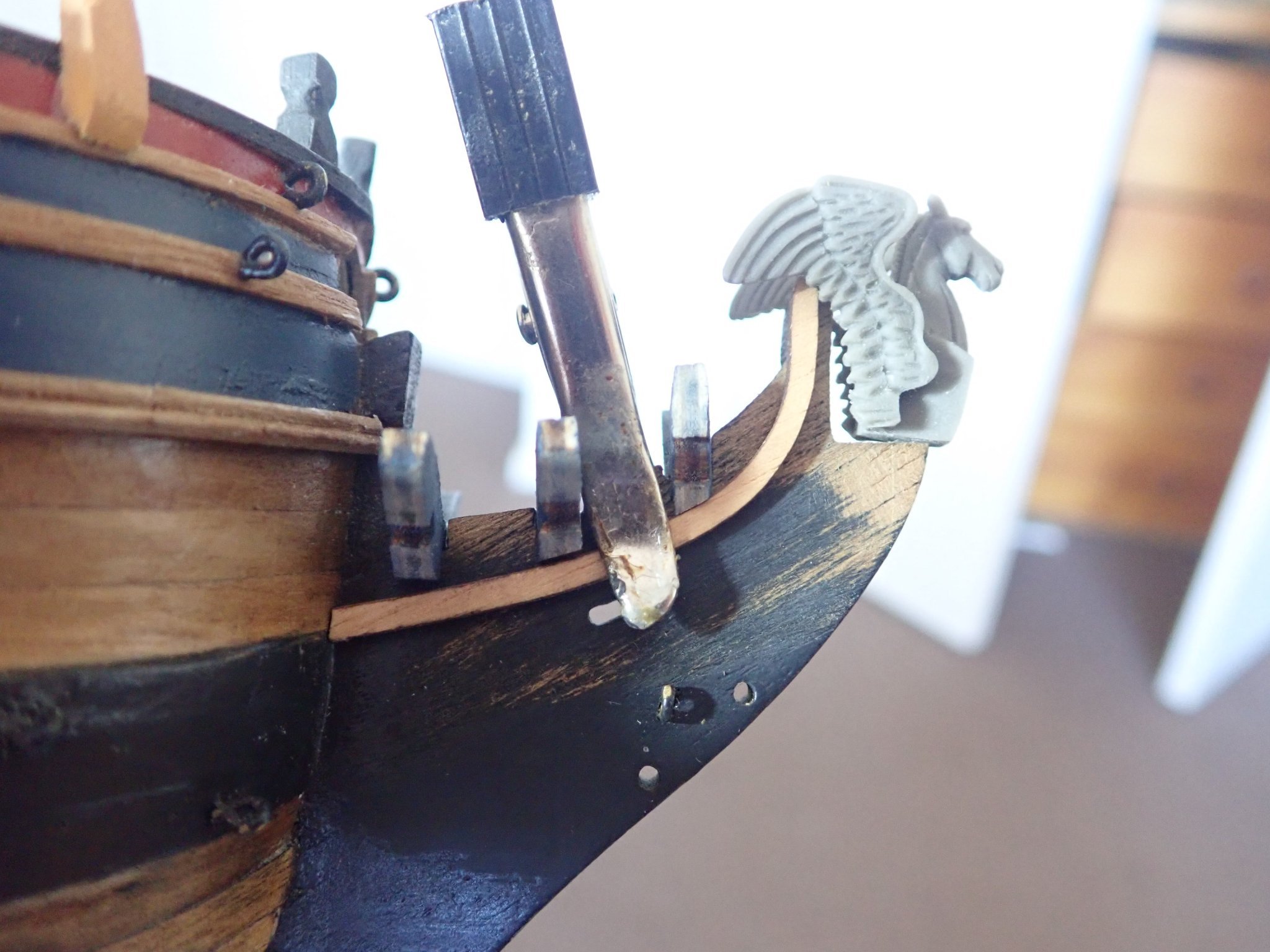
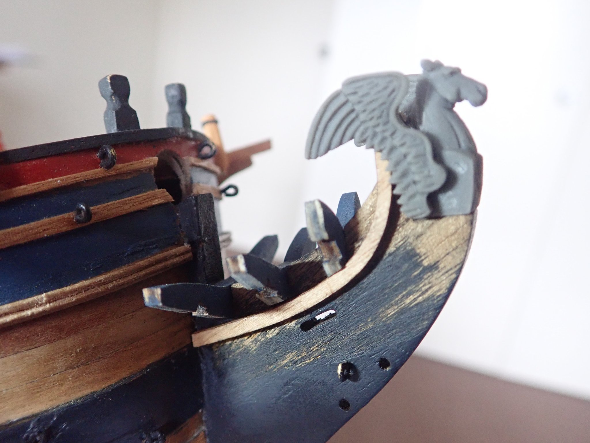
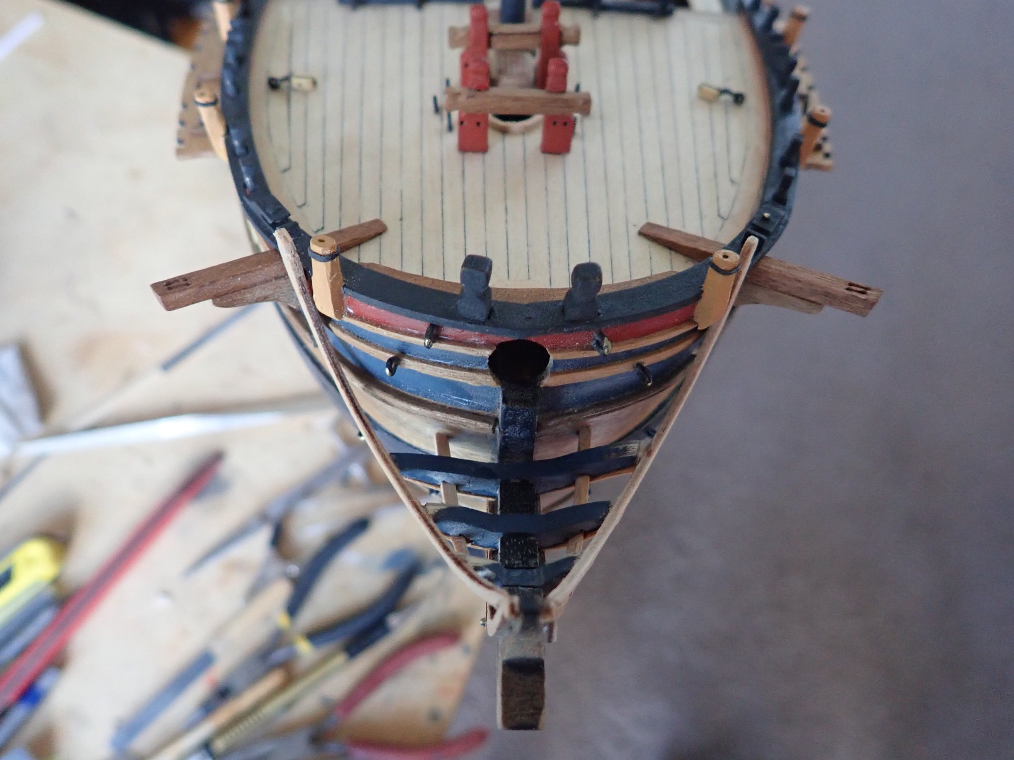
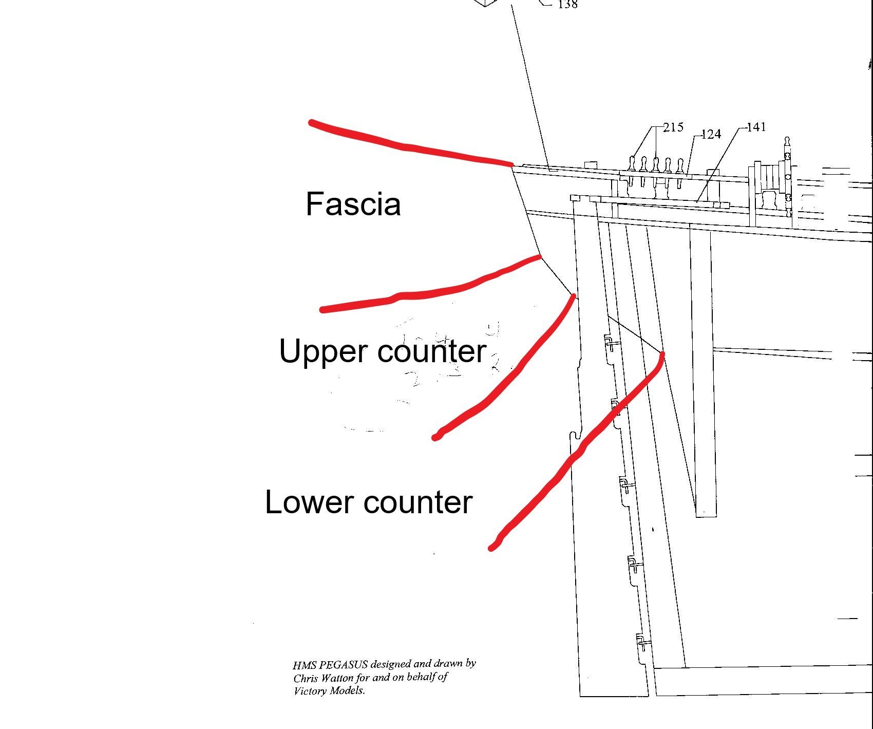
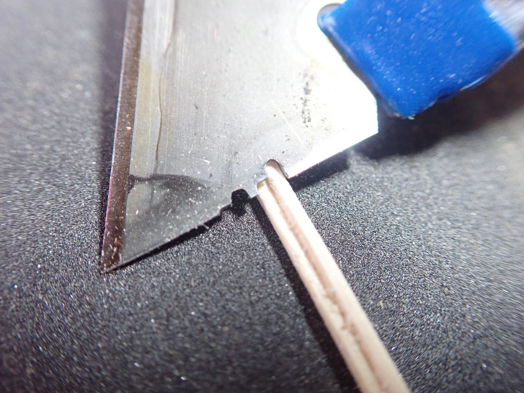
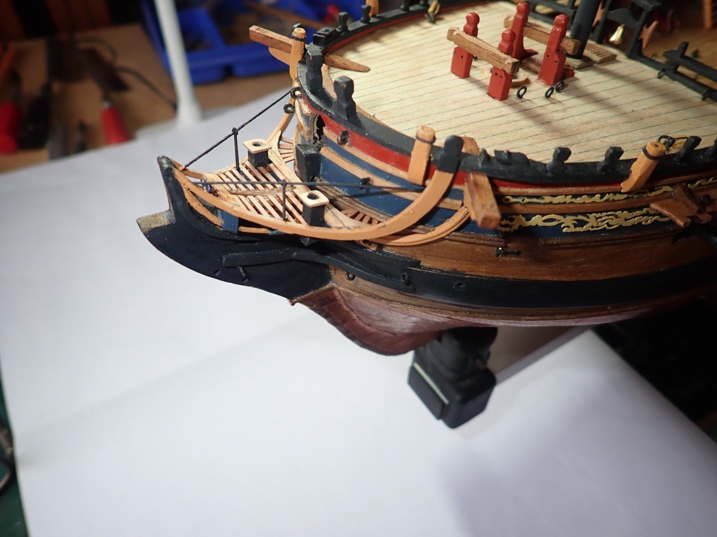
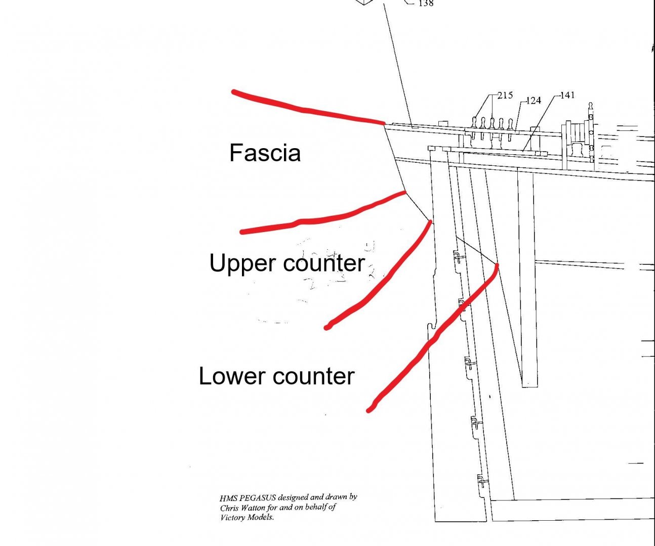
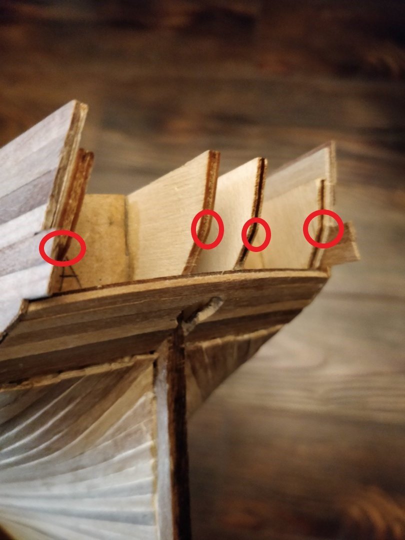
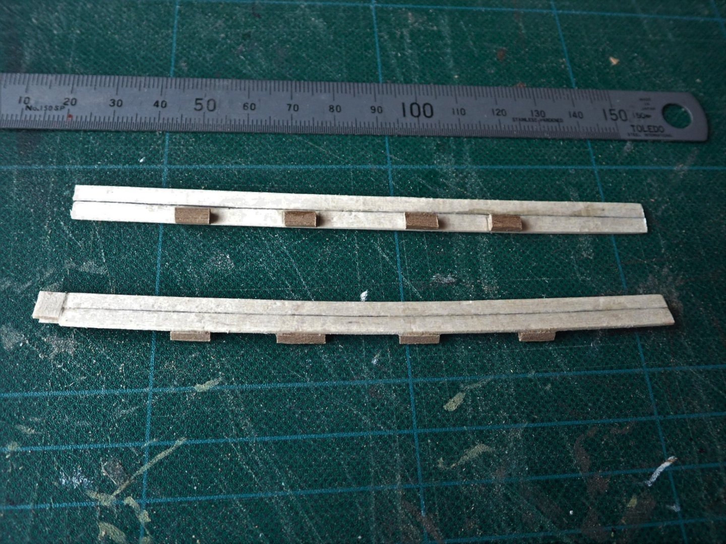
That's right it is. The first image, from a Pegasus plan, shows the the fascia and both counters (excuse the poor "straight" lines 🙂). In the second image, of your model, the lower extent of the fascia is shown by the red circles - not all of which are in exactly the right place, but you'll get the idea. Dry fit the fascia until you're happy with its placement. Some slight sanding of the four stern extensions may be required. For the moulding strips that seperate the different pieces, you could use 1mm square strip. I actually used 2mm square strips that I shaped using a tool made from a Stanley knife blade. I cut a profile in the blade using a Dremel with a cut-off wheel , but files could also be used. The image shows the blade with two profiles and a piece of strip with a profile cut in it. Simply drag the blade along the wood till you get the profile you want. Once you plank the decks you won't be able to remove them. Everything that you need/want on the upper deck has to be in place before you finally fix the ply false fore and quarter decks and plank them. This importantly includes the cannons that will be hidden by the fore and quarter decks. "Paralysis by analysis" strikes most of us at some stage 😁. Cheers

- 82 replies
-
- 2
-
-

-
- Fly
- Victory Models
- (and 2 more)
-
Probably not. Maybe the ply/walnut could be trimmed to shorten them and thus close the gap, but I certainly wouldn't force them into place. This would probably result in a disaster sometime later as the glue gives up. So long as the ply/walnut fits correctly elsewhere, then planking the deck will eliminate the gap. I'm not quite sure what you're asking. The side planking should overlap the planking of the upper and lower counters. Above those you have the stern fascia (this may be what you are calling the gallery) which itself extends out to the side and so overlaps the side planking. I would next plank the decks, only because you'll be able to run the Qdeck planks out over the stern, if the fascia is not in place, and so easily trim them to length. Then the fascia (?gallery) and finish the hull. All I can really say about the order in which you do things is - think it through and preferably several steps ahead. You're doing well, keep it up. Cheers.
- 82 replies
-
- 1
-
-
- Fly
- Victory Models
- (and 2 more)
-
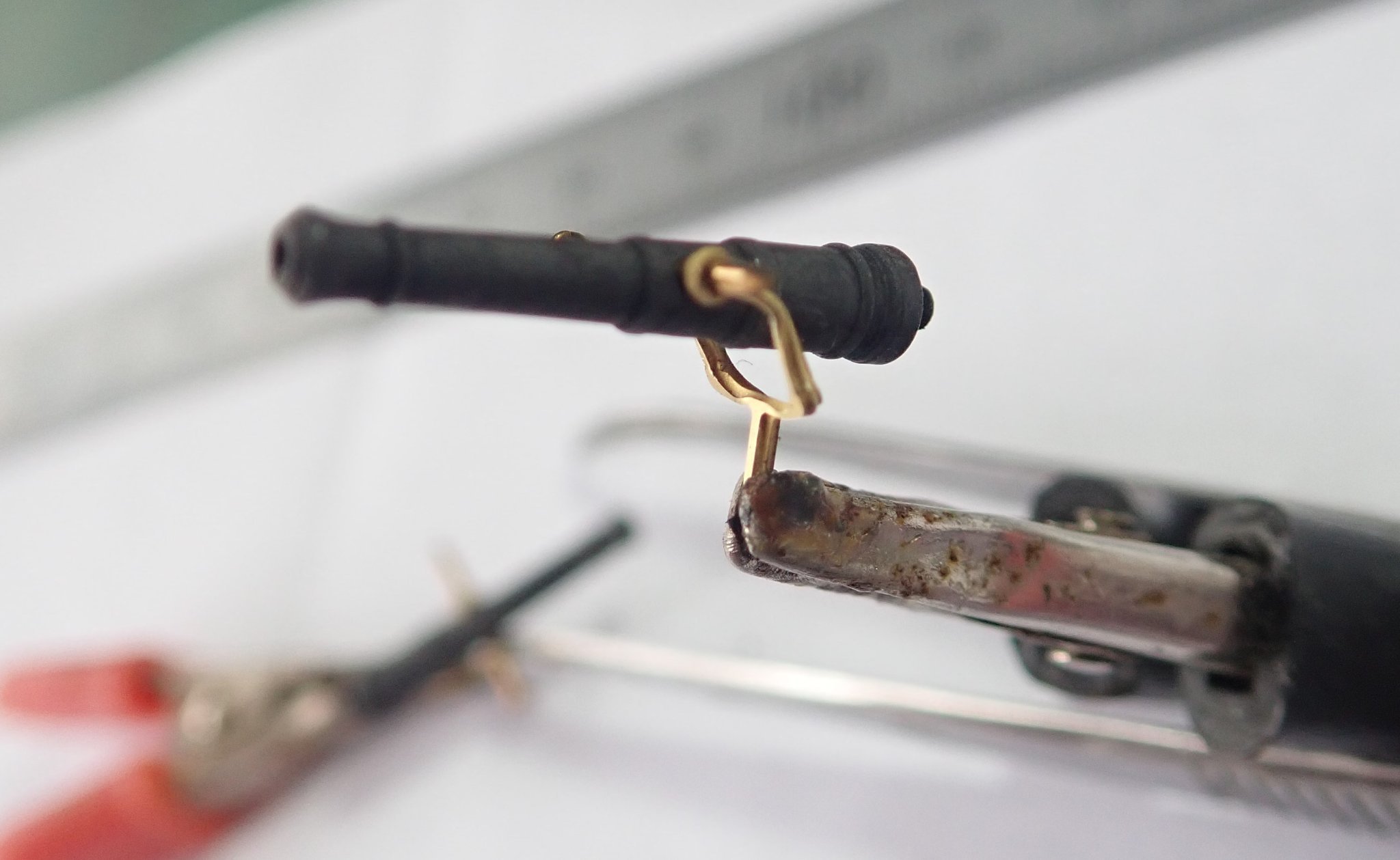
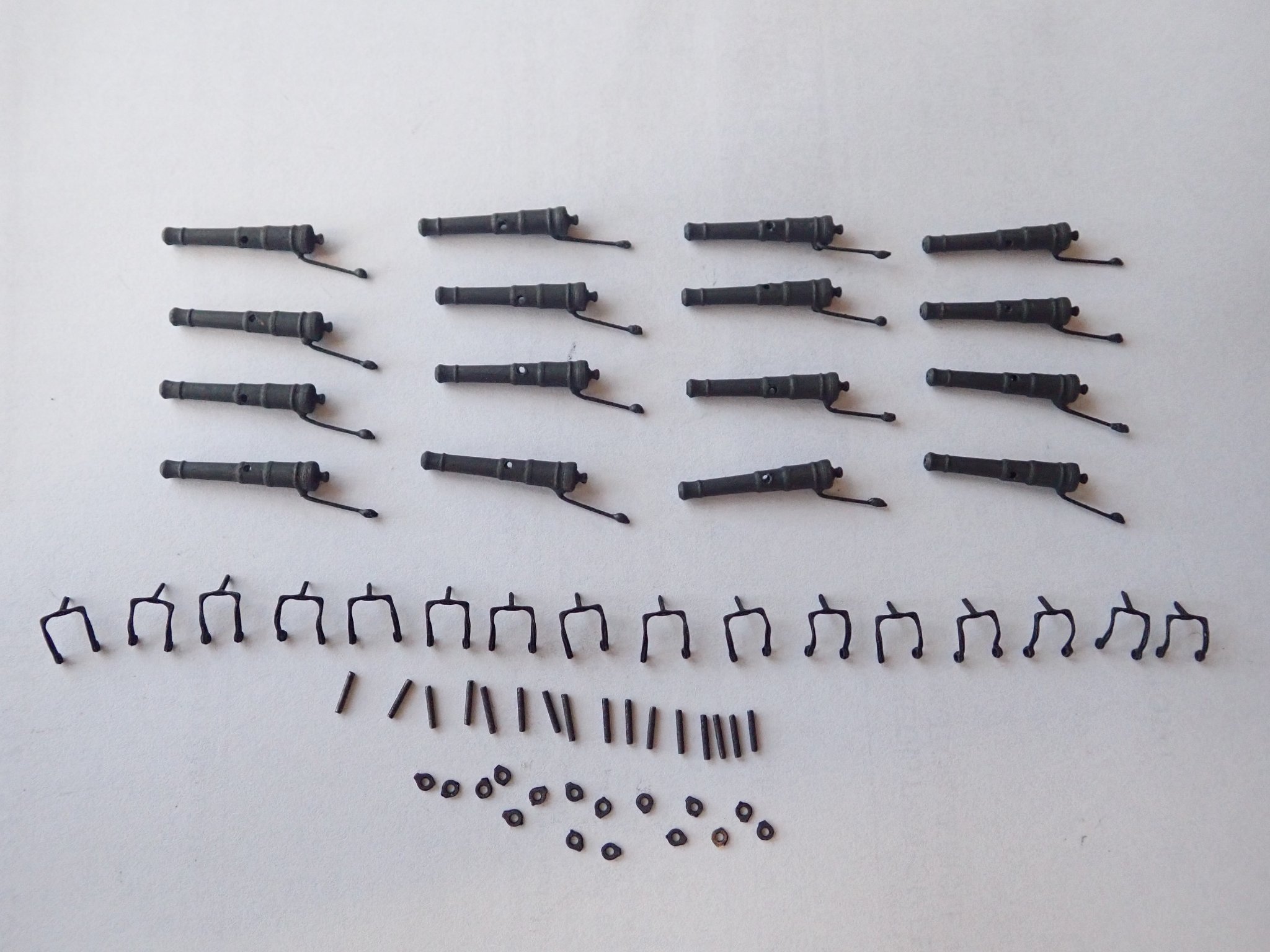
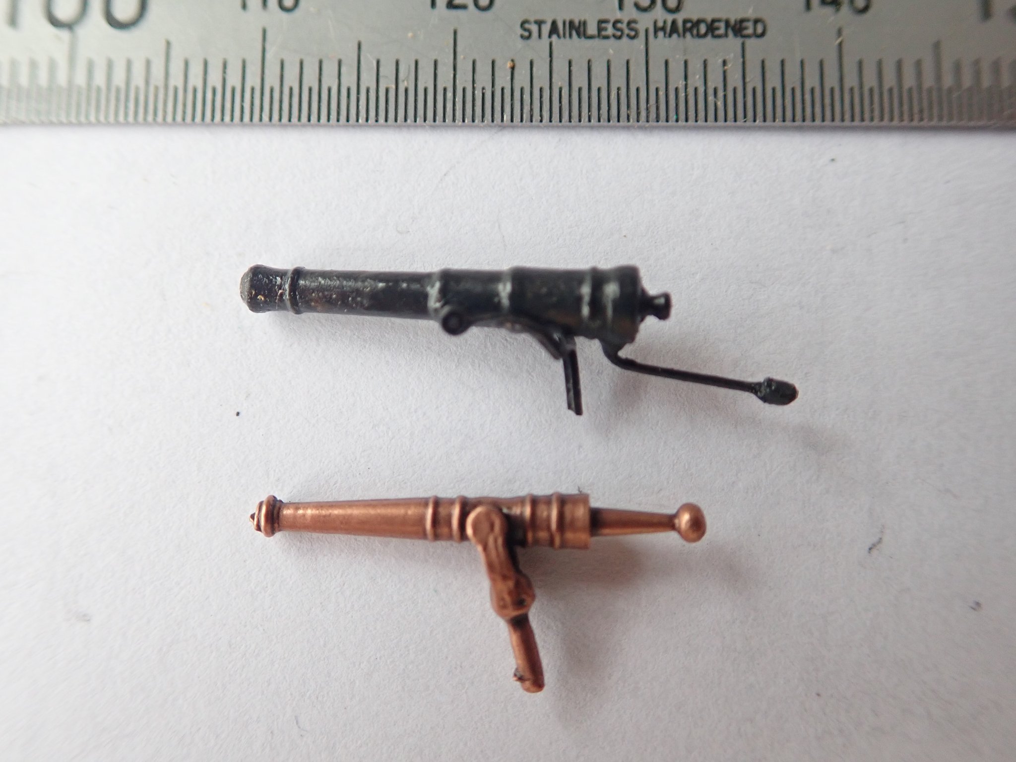
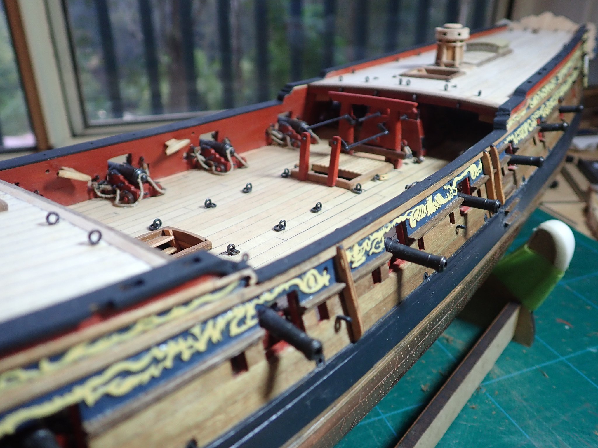
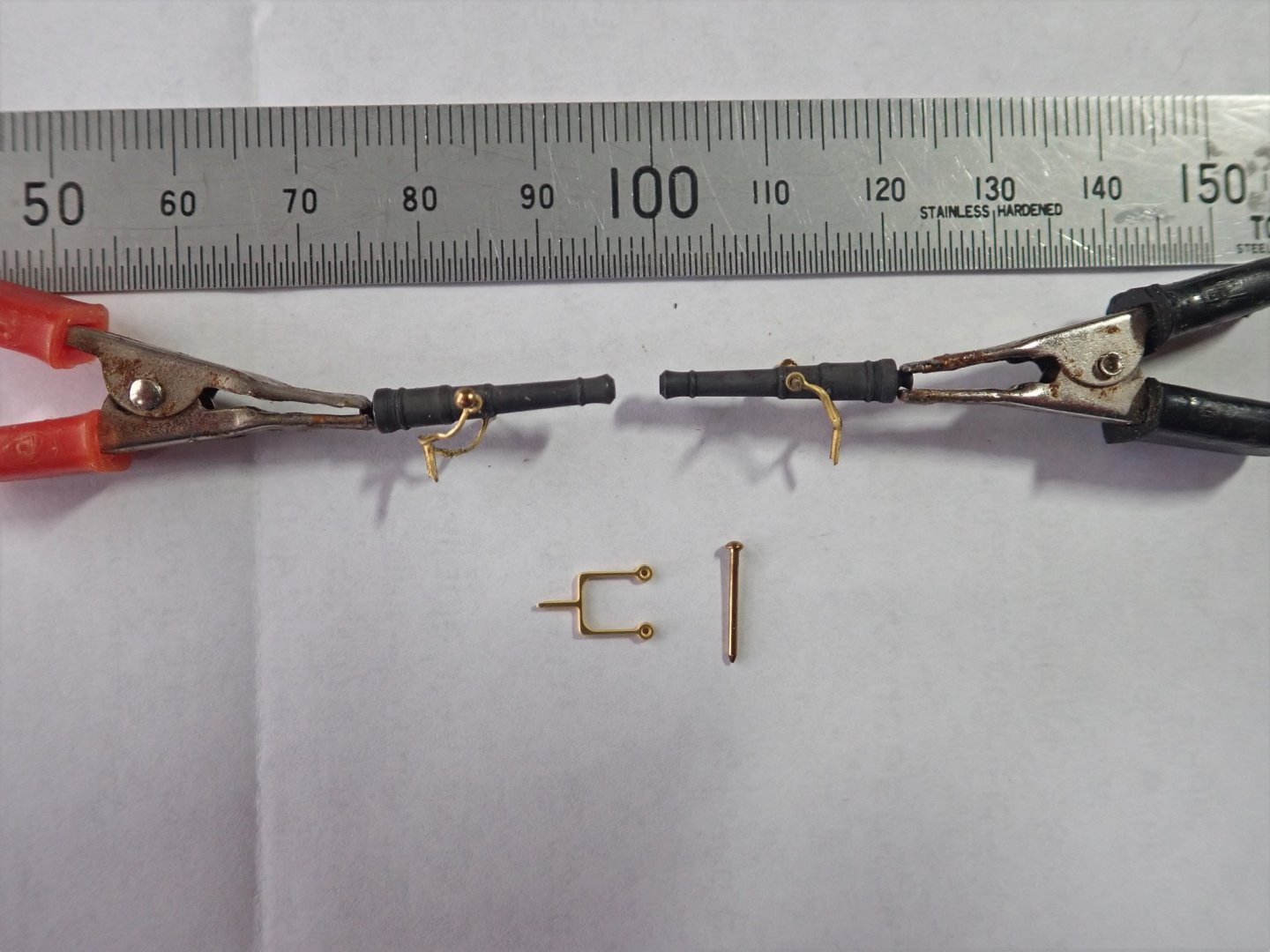
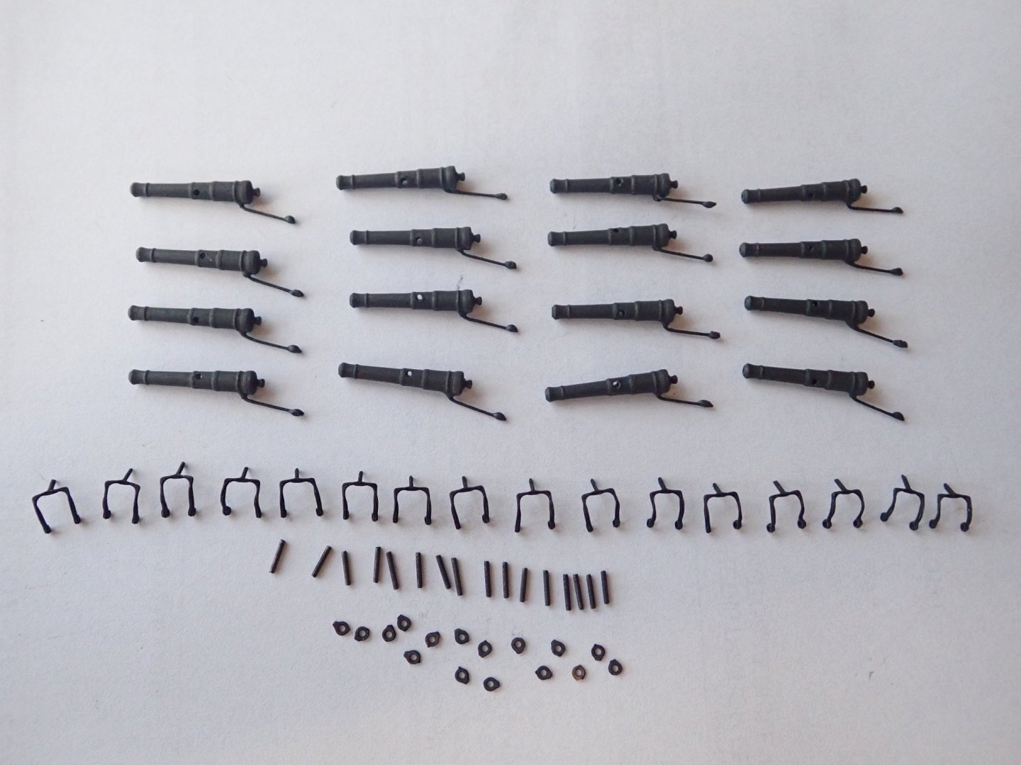
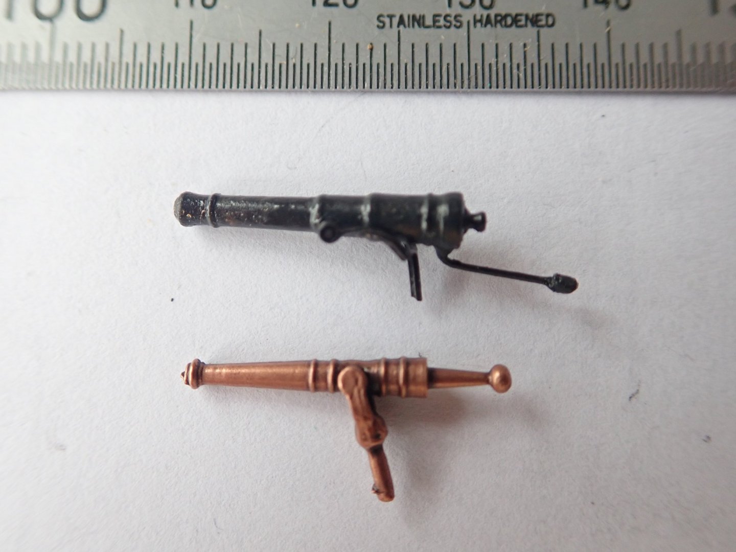
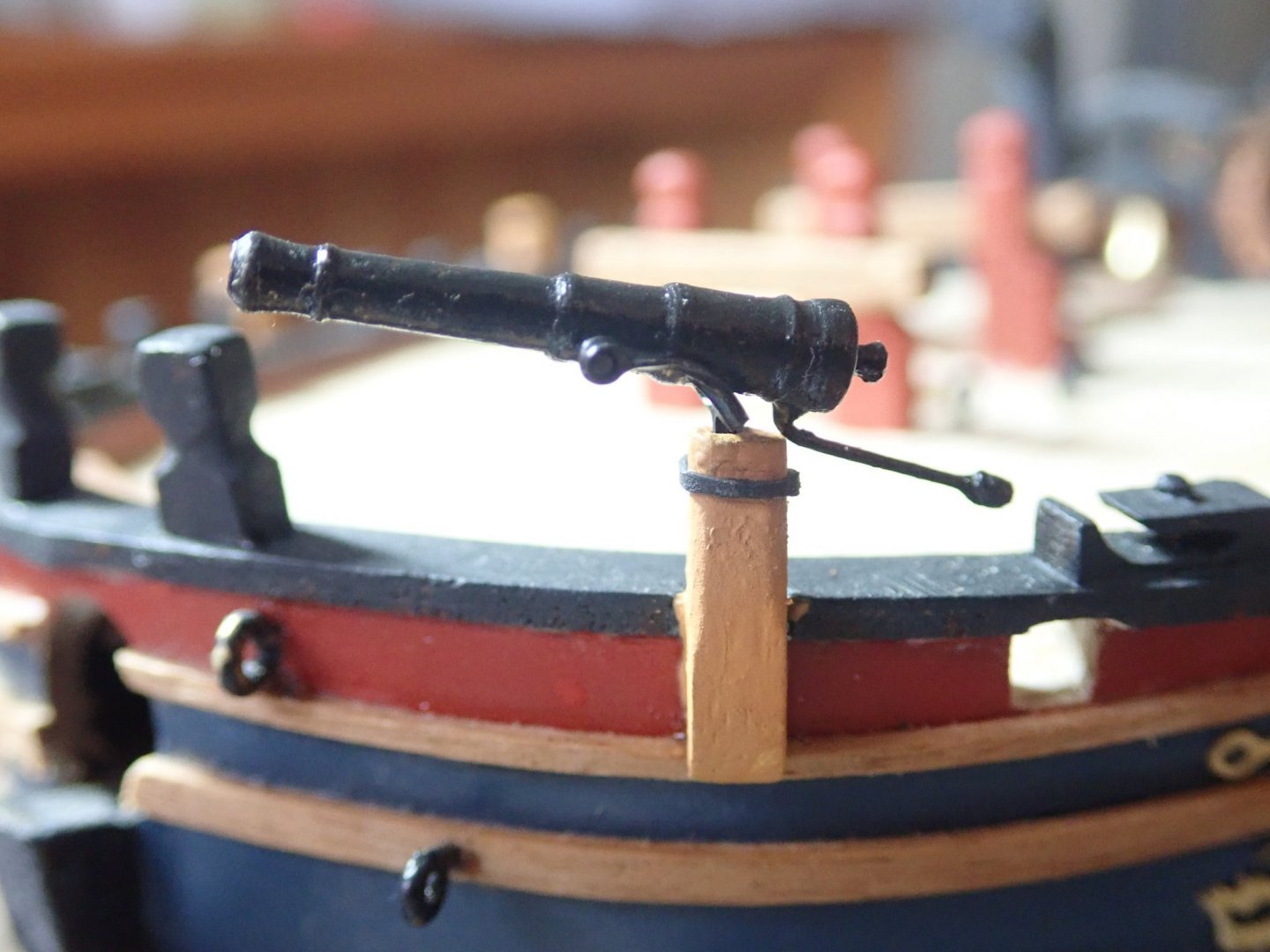
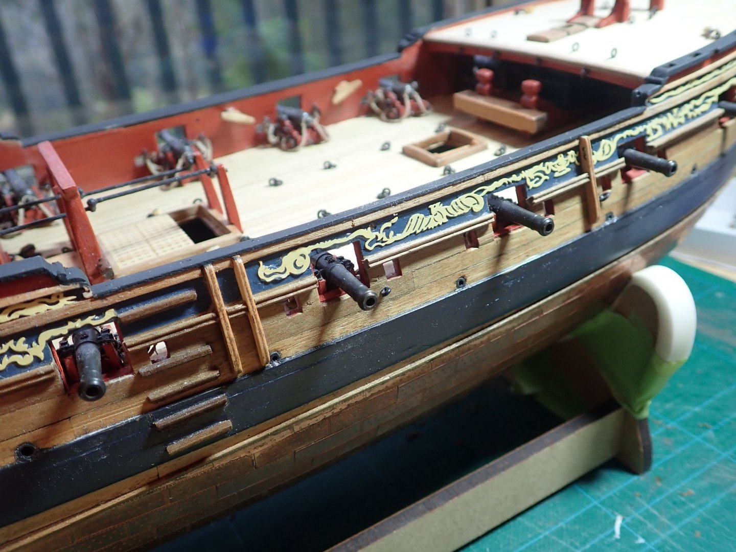
Thanks for the likes. All the swivel gun mounts are in place and now to deal with the guns themselves. The ones supplied in the kit are terrible, so guns were bought from Syren, nicely turned brass barrels, brass trunnions but no yokes. I initially thought that I would do what B.E. did and bend and silver solder together two brass hooks. I tried this but was unsuccessful. I then realised that because I was not going to install the hammock cranes, these could perhaps be used. The photo shows the first attempt (on the left) at adapting one of the cranes - rather rough. On the right is the second attempt, much better. Also shown is a hammock crane as supplied and a brass nail which I will have to cut down to use as the trunnion. The trunnions that came with Syren’s guns are too big to fit through the holes in the arms of the cranes, even after I had drilled these out as much as I dared. The new yokes are perhaps a little underscale, but even so, they look quite good. A 0.5mm hole was drilled in the gun and a short length of 0.5mm brass rod was epoxied in for the tiller with a blob of epoxy forming the knob at the end. The sixteen swivel guns ready for assembly. The small washers are to go onto the tops of the mounts as sockets for the yokes. One of the finished guns on a mount. Finally, this photo shows one of the kit guns compared to my version. That’s all for now, Cheers

- 104 replies
-
- 7
-
-
- pegasus
- victory models
- (and 2 more)
-
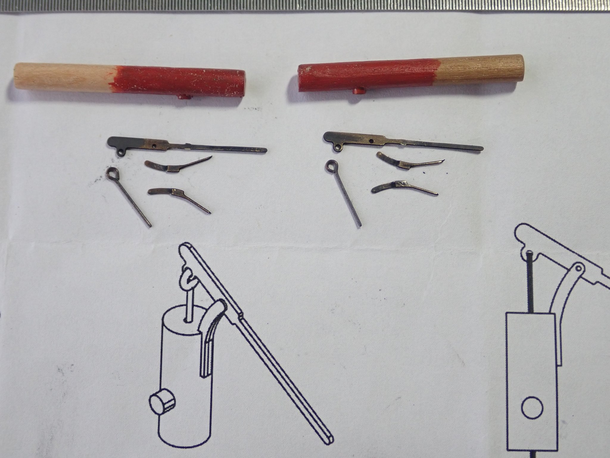
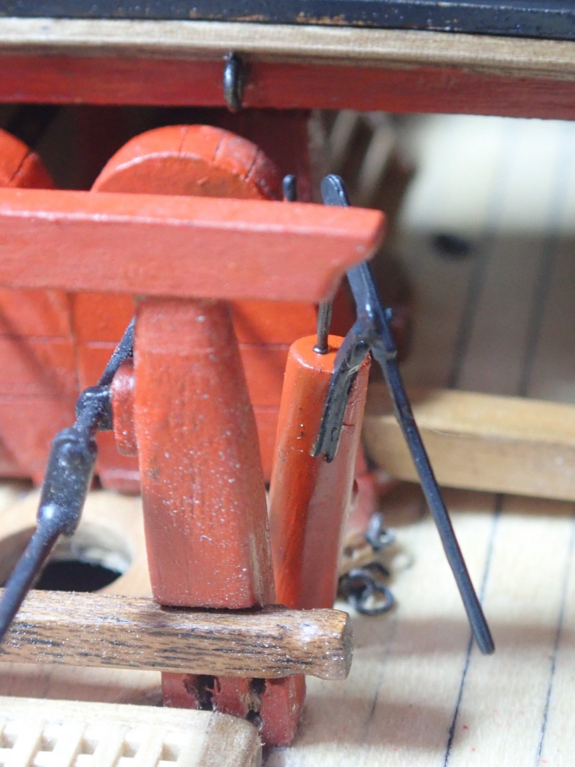
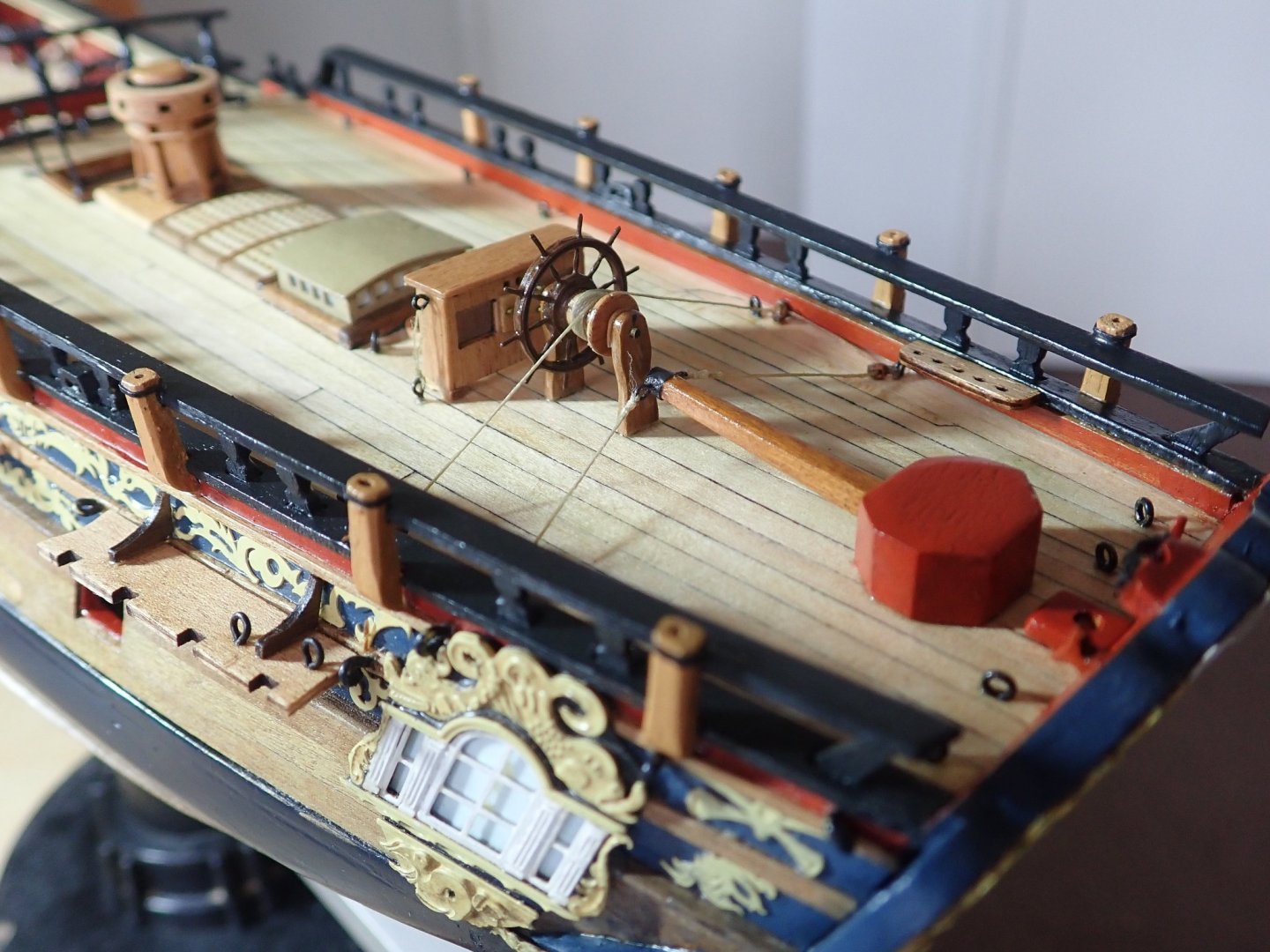
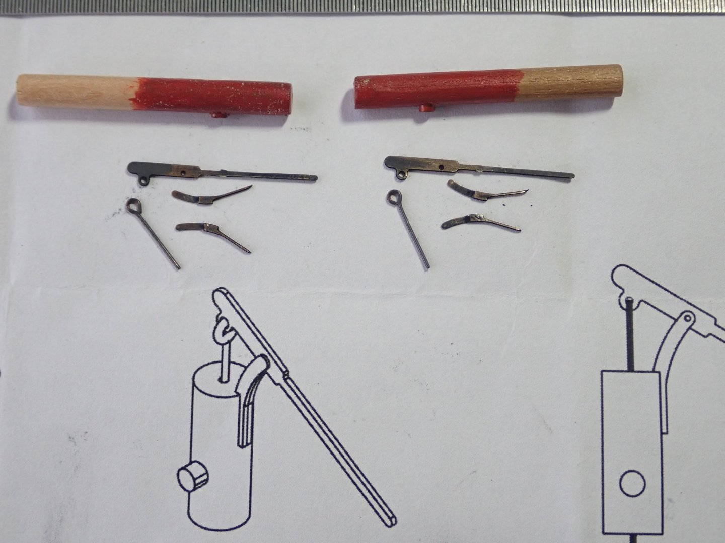
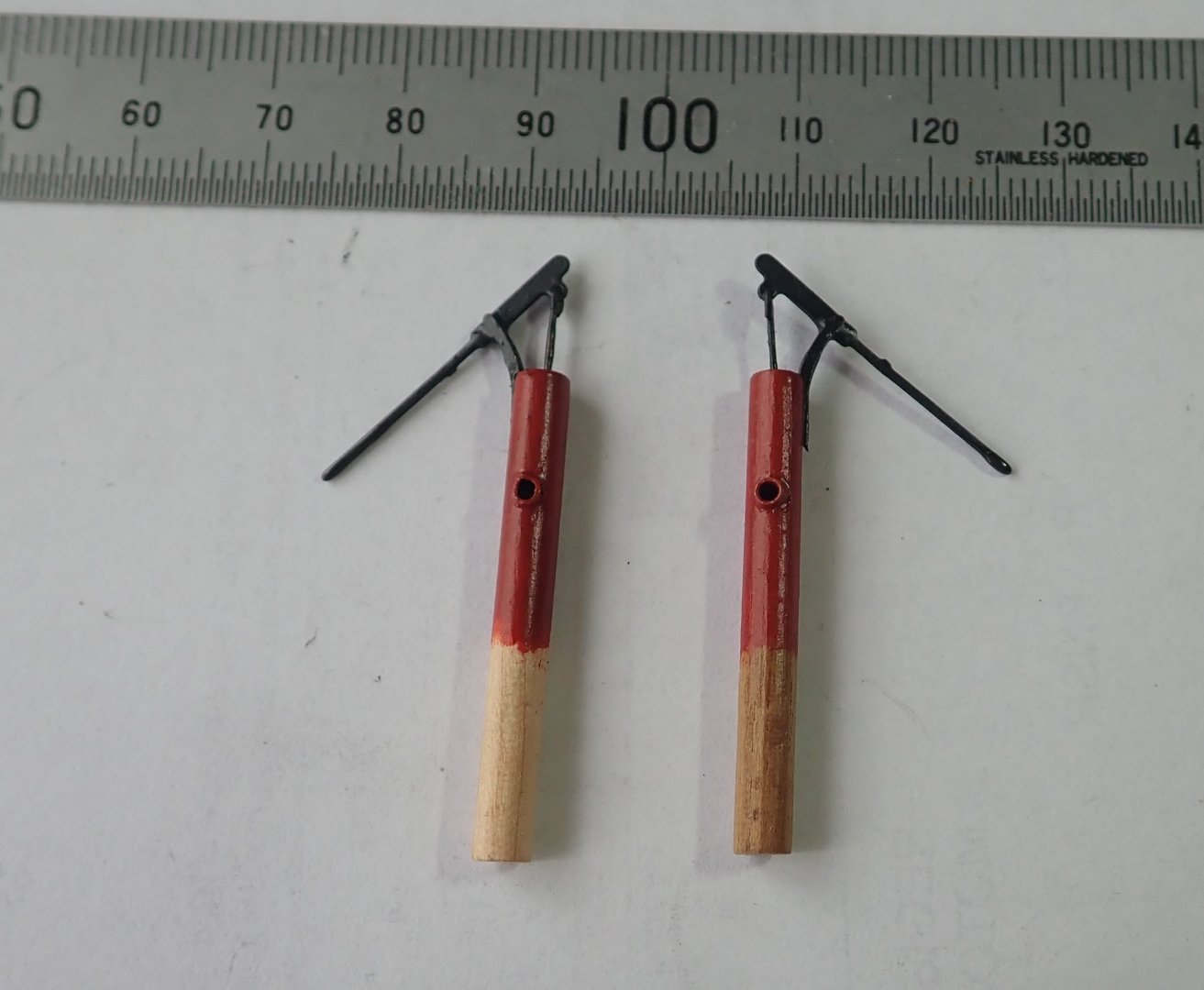
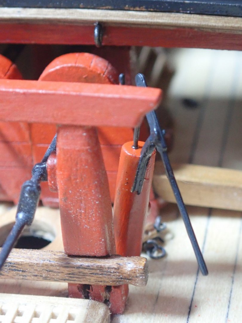
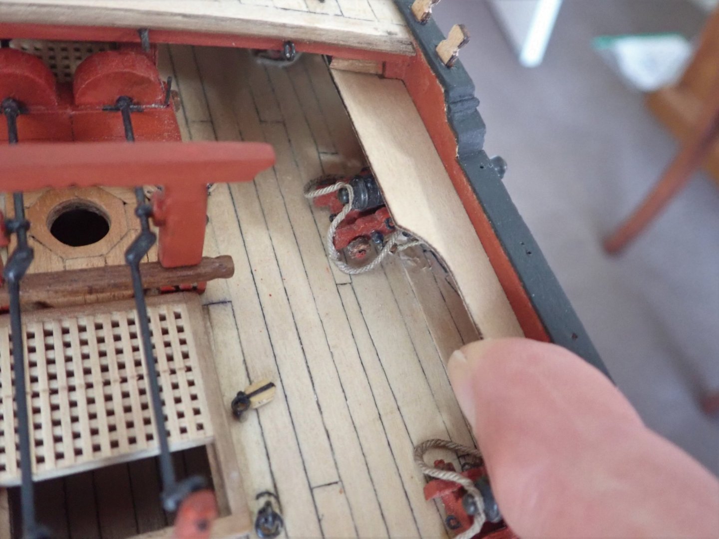
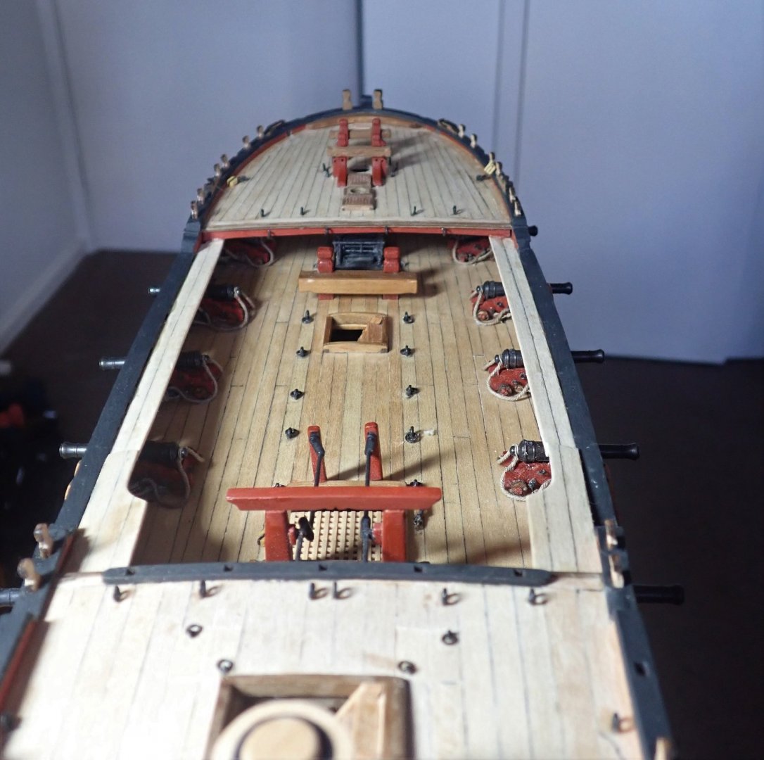
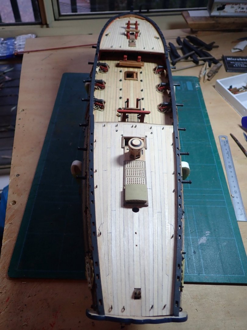
Thanks for the likes. The quarter deck cap rail is supported at its aft end by a simple post, and at the fore end by a pre-cut slot in the rail which goes over a post. In between these two are the five swivel gun mounts into which the rail slots. All seven points of fixing had to be aligned so that the rail formed a straight line in profile. To do this, I glued the rail to the aft post and the first and last gun mounts were similarly glued in place and adjusted so that the rail was reasonably straight - it did sag in the middle. The rail was just slipped onto the fore post, but not glued at this time. The remaining three gun mounts were then offered up to the rail and adjusted till the rail was straight. The join between the rail and the fore post was painted with glue, and after drying, the post was trimmed as it was overlong. The wheel had already been made, with a few changes from the kit. The end stanchions were simplified, the barrel was replaced as I did not like the appearance of the plywood one in the kit, and the wheel was rigged to the tiller following the diagram in TFFM, rather than the one in the plans. The binnacle was fastened in place. The Swan-class ships had two brake pumps (elm tree pumps) as well as the two chain pumps. The kit did not supply nor mention these. So, a Caldercraft kit for two pumps was bought. The instructions weren’t quite followed. The 4mm dowel supplied to form the body of the pump should have been cut into 13mm lengths and drilled length-wise through the centre (a 0.75mm diameter hole). A length of 0.7mm brass rod (the connecting rod) was to be fed through this hole, protruding through the bottom to make a locating peg, and formed into a small loop at the top to take the brake handle. I decided to cut a 4mm dowel into a length sufficient to reach the lower deck of Pegasus and to give the 13mm length suggested for the body of the pump above the upper deck level. A short hole was drilled in the top for the connecting rod for which I used a pre-formed eyelet. Caldercraft supplied 2mm dowel from which to make the outlet - I had some thin walled brass tubing which I used instead. The hole I made through the upper deck was angled as the pumps were not perpendicular to the deck. The instructions call for the pump, when in place, to be oriented so that the handle pointed aft and the outlet forwards. The TFFM says the opposite and this is the way I will install them. When looking at the space available, this is more logical as there is room for a sailor to operate the pump. Also the outlet now points directly at the scupper that the chain pump drains to. The parts to the pumps with the extra long dowel. The completed pumps, and I was careful to make port and starboard ones. One of the pumps in place. They’ll be permanently installed later. The next installment will be all about swivel guns. Cheers
- 104 replies
-
- 4
-
-
- pegasus
- victory models
- (and 2 more)
-
Just as an aside B.E., I hope you're backing up your build log - I'd hate for you to have to try and recreate it (as you did with Pegasus) if there is another system crash. Cheers
- 857 replies
-
- 2
-
-
- Sphinx
- Vanguard Models
- (and 1 more)
-
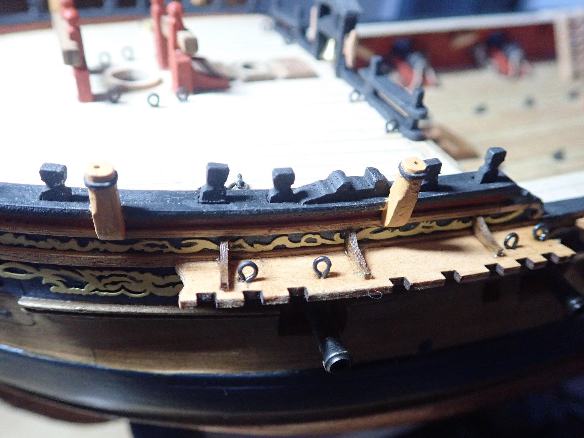
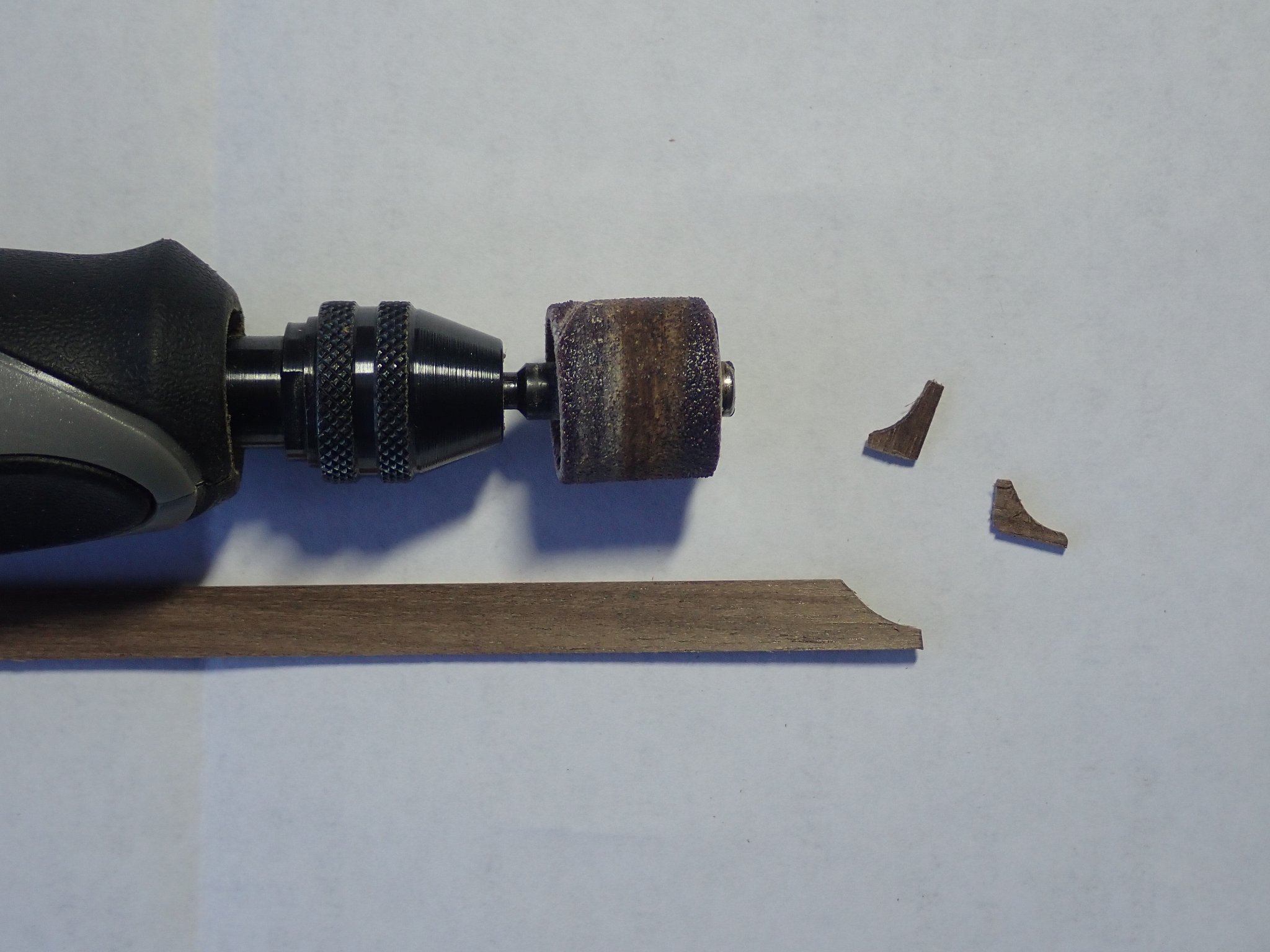
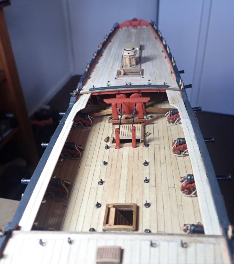
Thanks for the likes and comments. The two ladders in the waist, the swivel gun mounts at the bow, the tiller, the cover over the head of the rudder, the pin rails and the channels were all added. The wheel and binnacle will both be added later as I think they would be a little vulnerable to being knocked at the moment. It was immediately apparent that the channels lacked something - the supporting knees. The kit makes no mention of these, but TFFM says that the fore channel has three, the main four and the mizzen two. So knees were made from suitable strip and glued in place. A Dremel with a sanding drum was used to put the curve into the knee and it was then simply cut from the strip. There is a however, however. The knees butt against the hull between the two rails that have already been installed with PE decoration between them. Removing the PE, trimming it to allow for the knees and reinstalling was never an option. Neither was trimming the PE whilst in place. So the knees are simply glued against the PE decorations. Although close inspection would show this, the knees will be hard to see behind the rigging. The Dremel and two knees that have been parted from the strip. The tops of the swivel gun mounts were sanded to an octagonal form, but this is not readily apparent. The black “iron” bands around the tops of the mounts are heat-shrink tubing. The fore channel and two of the mounts. That's all for now. Cheers


- 104 replies
-
- 7
-
-
- pegasus
- victory models
- (and 2 more)
-
Chris, I've just got to ask...."starving cow" problem with card models? I'm really curious because my first card model (a Murray River paddle boat) is on its way from Europe, but more of that when it arrives. And I'm following your build log with much interest. Cheers
-
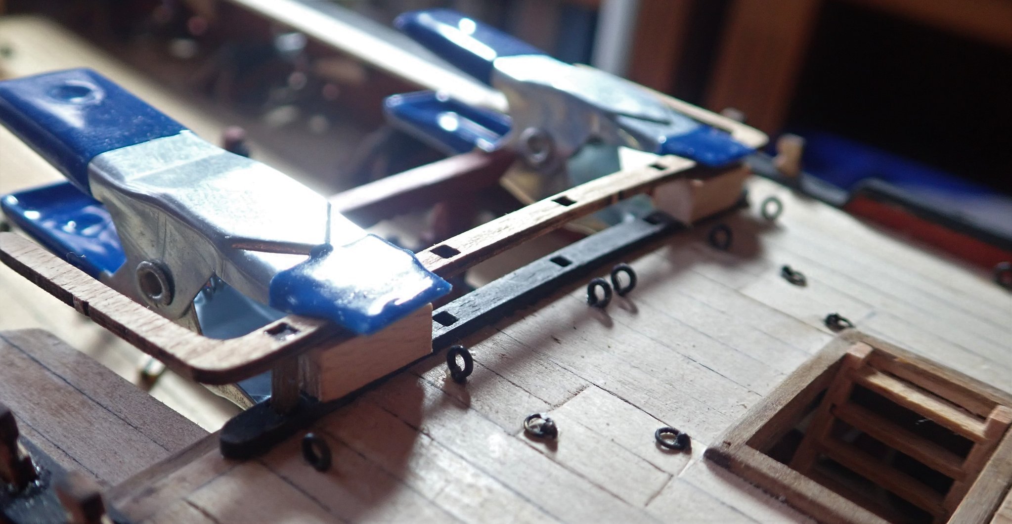
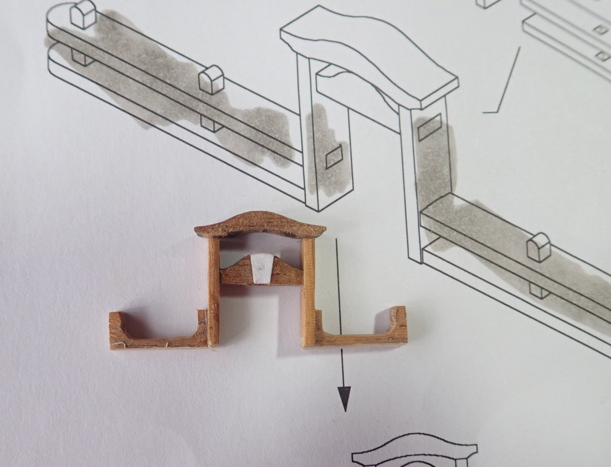
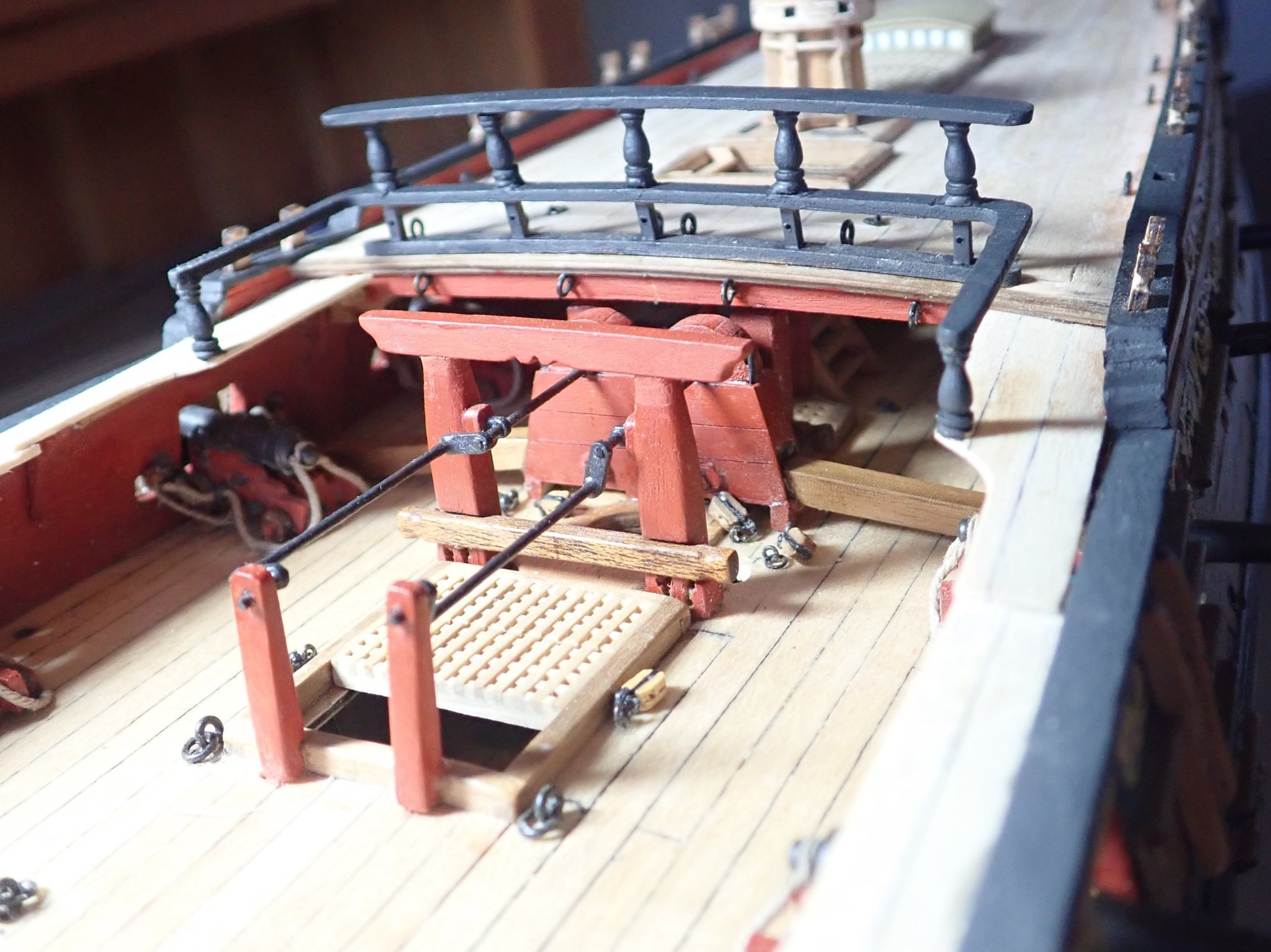
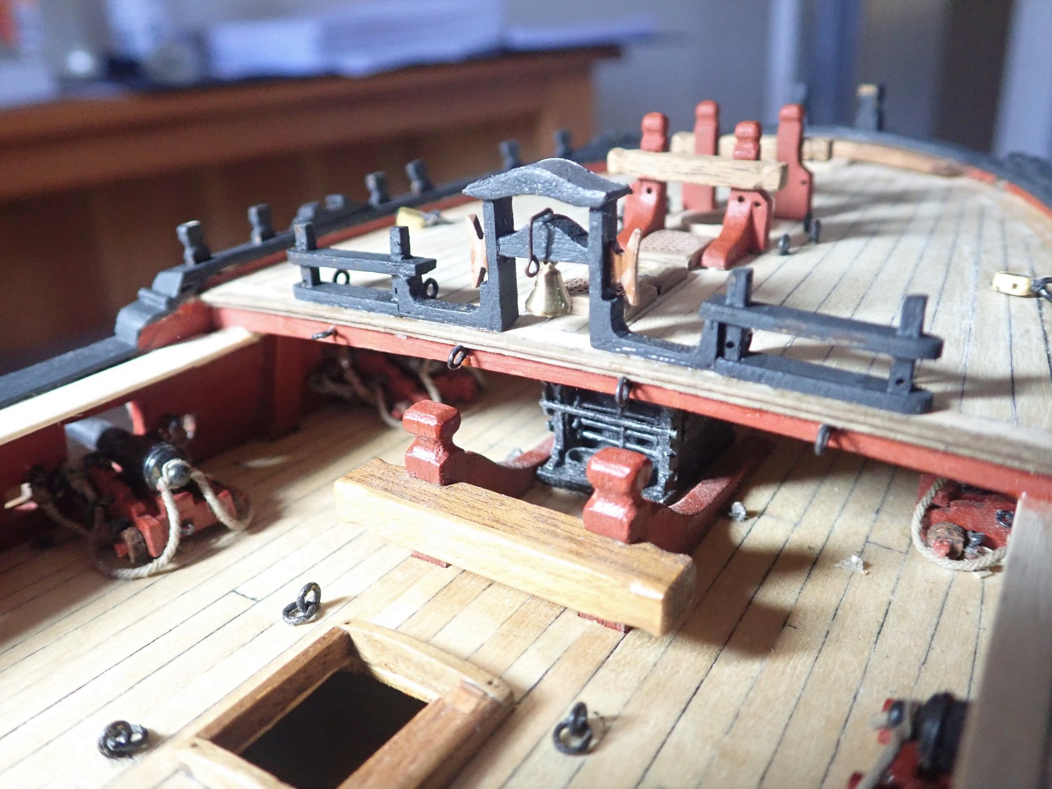
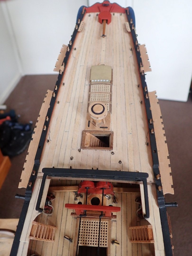
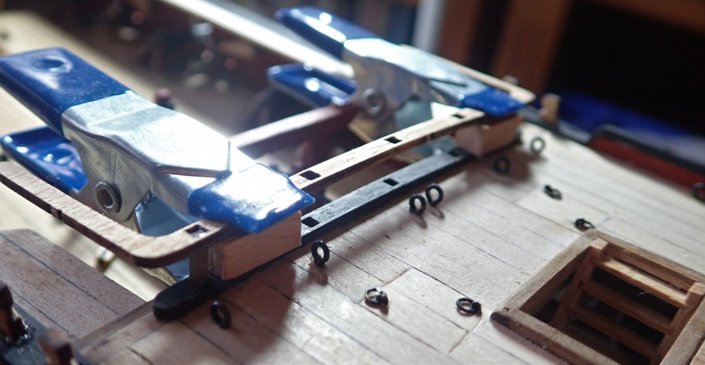
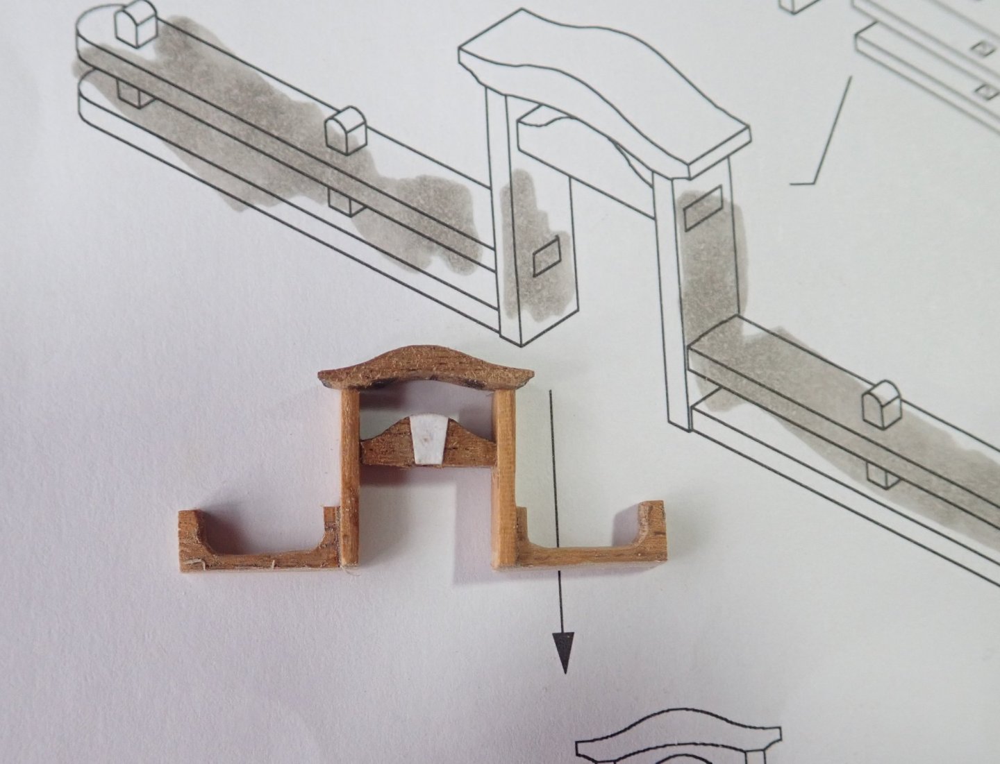
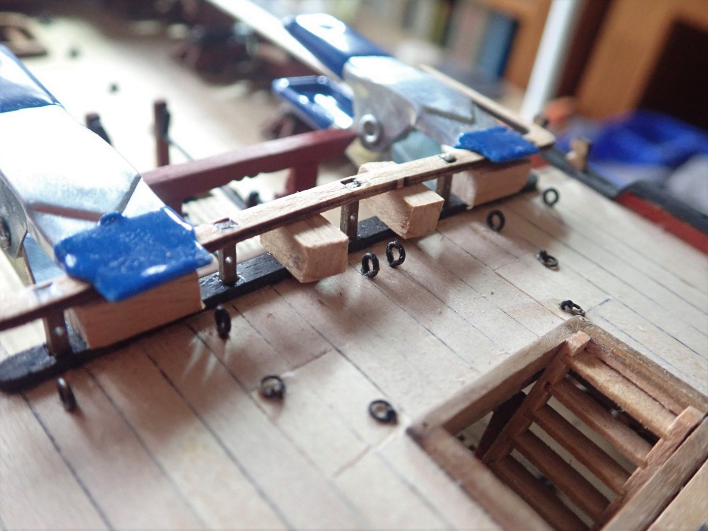
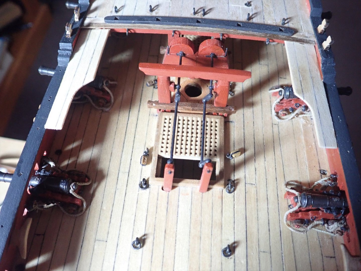
Thanks for the likes. The quarterdeck breastwork was the next thing to be done. This proved to be an exercise in frustration. There are three rails, the lower glued to the deck, the middle separated from the lower by square posts and the upper separated from the middle by turned pillars. The first part was easy as the lower and middle rails had square holes cut into them and the posts simply slotted home. The two outside posts were glued in place in the lower rail first, then the middle rail was glued to these, using blocks to keep the distance apart correct. The remaining posts were then glued in place, again using blocks to ensure correct distancing of the two rails. Gluing the pillars to the middle and upper rails was the frustrating part. As the pillars had to be vertical, and the rails were curved to match the deck, their tops and bottoms had to be carefully sanded to allow this. There were no holes to locate the pillars, they sat flush on the middle rail and the upper rail sat flush on them. To make things a little easier, the upper rail was prebent using a plank bender. Still, clamping this lot together while glue dried was not possible. So five minute epoxy was used with gentle finger pressure holding everything in place. Success occurred after several attempts. The middle rail curves around to lie above the gangways, with support being a newel post at the end. As I had modified the gangways, the supplied post was far too big. Fortunately, there were several spare turned pillars and as luck would have it, they were exactly the right height to be used here. The completed breastwork. I then tackled the belfry and modified the kit version to better resemble that shown in TFFM. The continuous rails each side of the actual belfry were trimmed and new cradles made. These will support one end of the spare spars, their other ends lying on the gallows. The photo shows the modified belfry (the small white patch is an iron reinforcing band, it will of course be painted) and the diagram of the kit version. The completed belfry. Although not obvious, the roof over the belfry is covered with lead (as per TFFM) - actual lead too, a piece of very flattened solder. Cleats were added to the belfry. A dowel in place showing how the spare spars will be carried. Cheers


- 104 replies
-
- 9
-
-

-
- pegasus
- victory models
- (and 2 more)
-
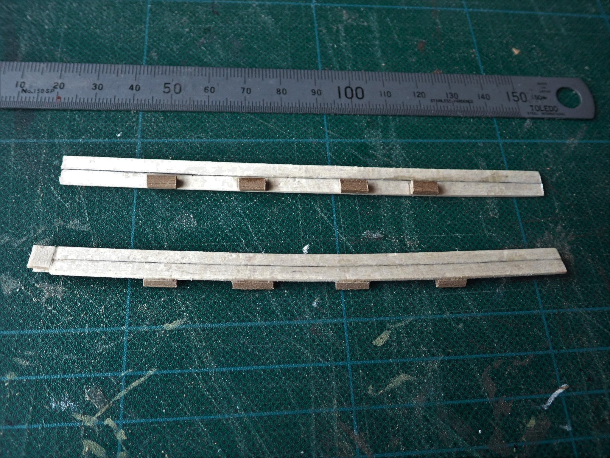
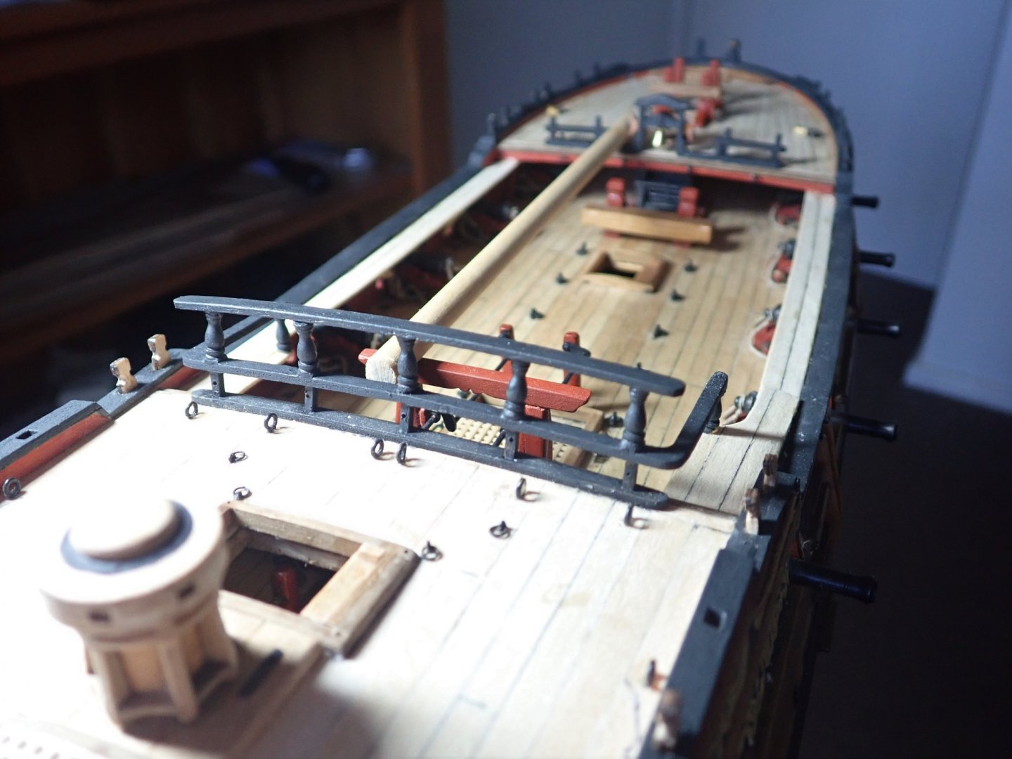
Thanks for the likes. The kit supplies gangways which extend from the quarterdeck forward for a short distance. I decided to follow TFFM and add gangboards which will run from the end of the gangways to the foredeck. There are several consequences to this decision - the gangways have to be raised a few mm so that they are very slightly above the level of the cap rail in the waist, the two ladders leading from the upper deck to the foredeck are no longer required, there is no mention in TFFM of hammock cranes along the cap rail in the waist so these will be omitted, and there are stanchions along the waist cap rail now with a rough tree rail on top. The photo shows the supplied ply gangway held in place as per the instructions. The gangway needed to be raised, which required trimming of the aft end so that it would fit flush against the quarterdeck breast beam rather than being below it. The ply also needs to be faced with planks. If I’d used the ply, I would have had to hide it’s exposed edge, so rather than do this, I made new gangways of edge joined planks. I didn’t think that simple edge gluing of the gangway against the bulwark was going to work very well, especially as the gangway is supposed to be slightly higher than the cap rail, so I added two blocks on the underside of the gangway to give a much larger gluing area. The photo shows the new gangways, trimmed to fit, with the knee and blocks. Only one knee is shown in TFFM, not the two supplied in the kit. The new gangways in place. The gangboards were made by edge gluing two, pre-bent, planks together. Four knees are supposed to support the gangboards, but in spite of several attempts,I couldn’t get these in place, so resorted to Plan B - gluing small blocks along the edge of the boards and then gluing the boards to the bulwarks. Fixing the knees in place would have been very easy if I had planned on adding the gangboards early in the build. The blocks are not visible, and I don’t think the knees would have been either. So, the gangways/gangboards are in place. Cheers

- 104 replies
-
- 8
-
-
- pegasus
- victory models
- (and 2 more)
-
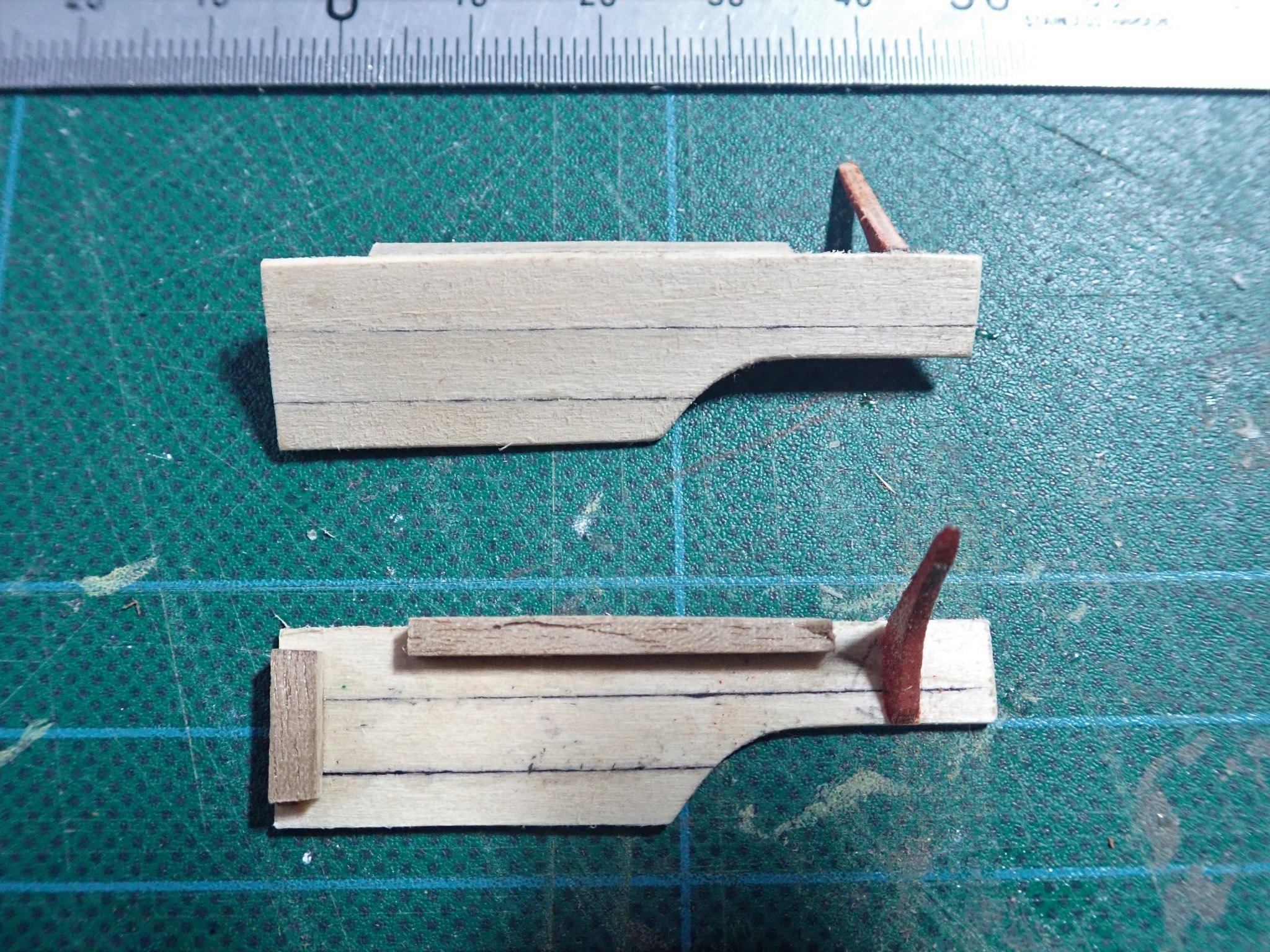
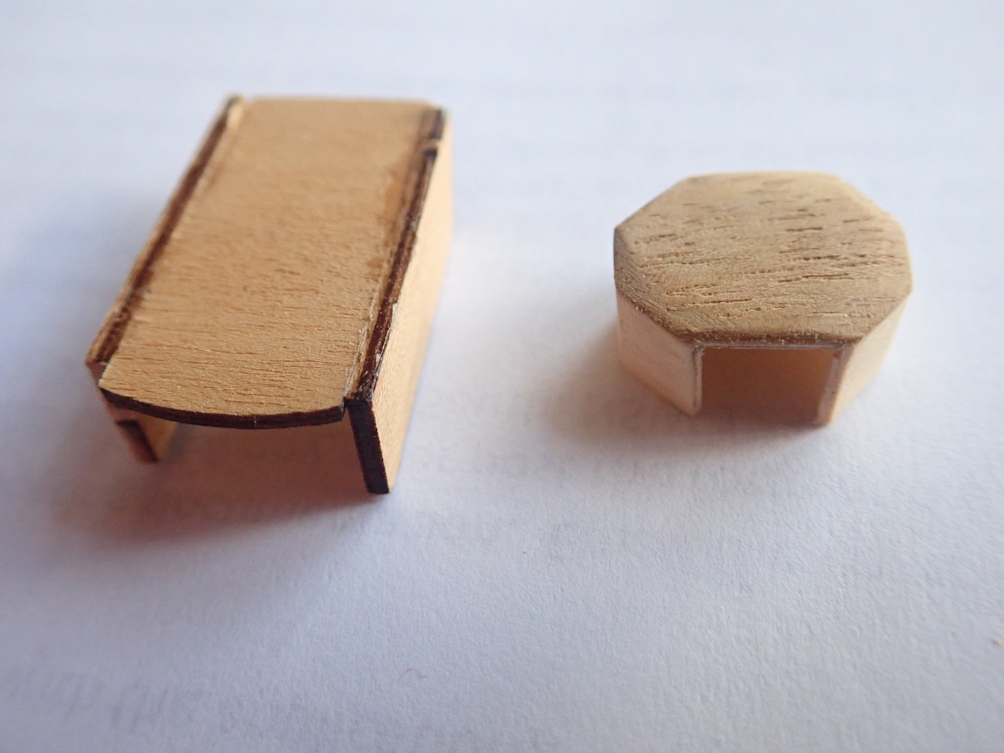
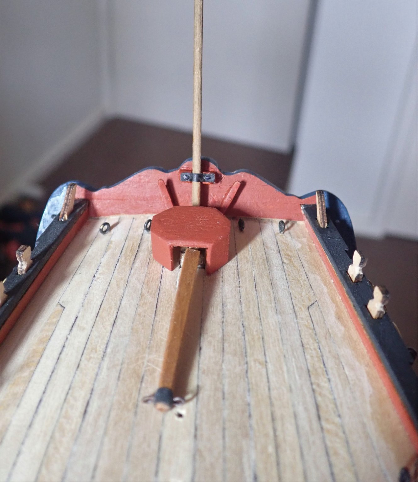
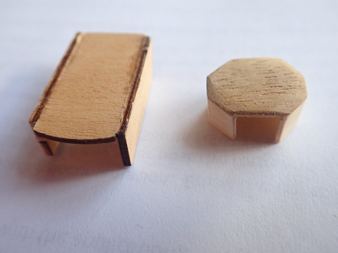
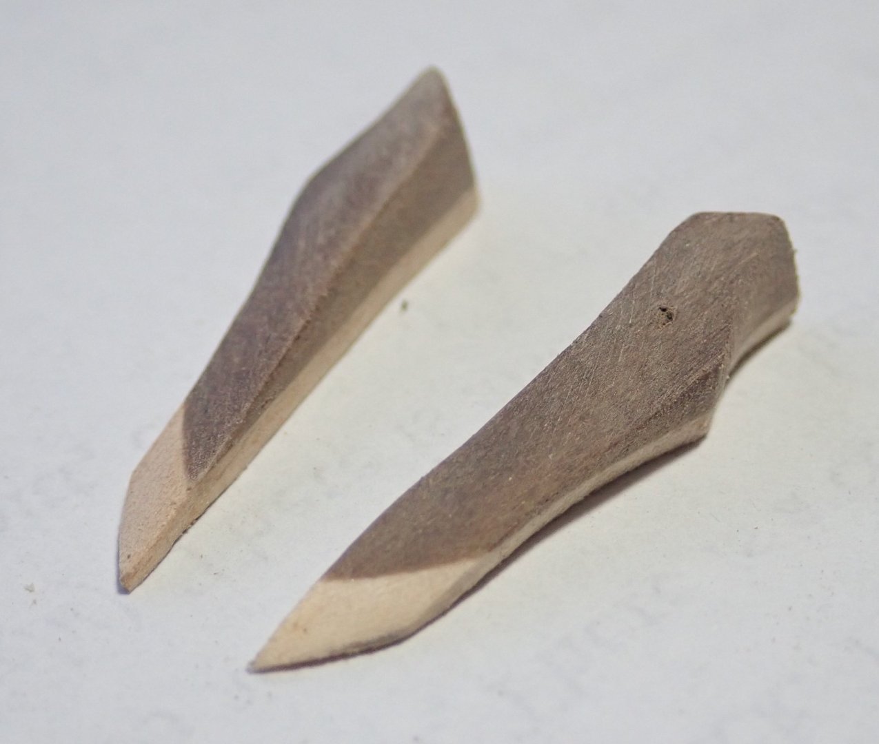
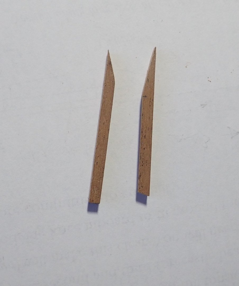
Thanks for the likes. A short update. The gap under the outboard end of the tafferal will be filled with a quarter piece, which will extend down to the wale. It’s a complex shape as it has to blend with the counter, be shaped to suit the PE decoration which will adorn it and taper to nothing at the wale. The photo shows the two quarter pieces after shaping. Each is about 25mm long and is laminated simply because I didn’t have a suitably sized piece of wood - they are to be painted. Two photos showing the piece in place. I didn’t like the rather ugly box (on the left in the photo) that was provided as the cover over the rudder head, so I made a new, smaller, octagonal one. In doing so, I freed up enough room between the rudder head and the transom to install an ensign staff, following the description in TFFM. The staff apparently has two small sheaves in the cap, so I’ve assumed two halliards would be present and I’ve added two cleats on the transom for them. I also made a new tiller and attached two small rings at its end with a simulated iron band. Cheers


- 104 replies
-
- 7
-
-
- pegasus
- victory models
- (and 2 more)
-
Yes, I agree. I actually made the two quarter pieces this afternoon, and have glued them in place. I'll look at them tomorrow and if they look OK, that'll be great, otherwise off they'll come and I'll have another go. All good fun 🙂. Cheers
- 104 replies
-
- 1
-
-
- pegasus
- victory models
- (and 2 more)
-
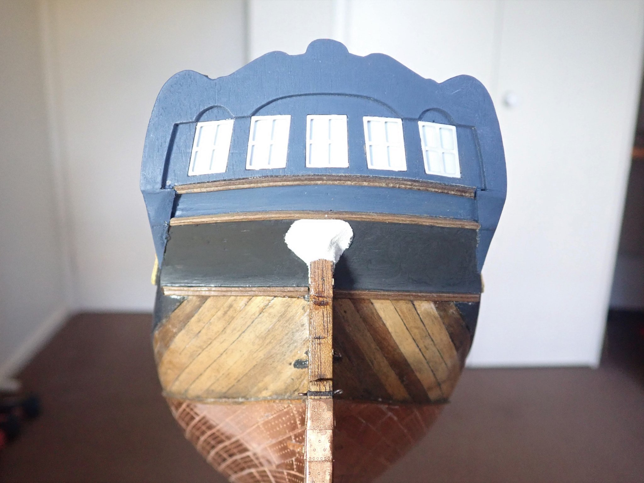
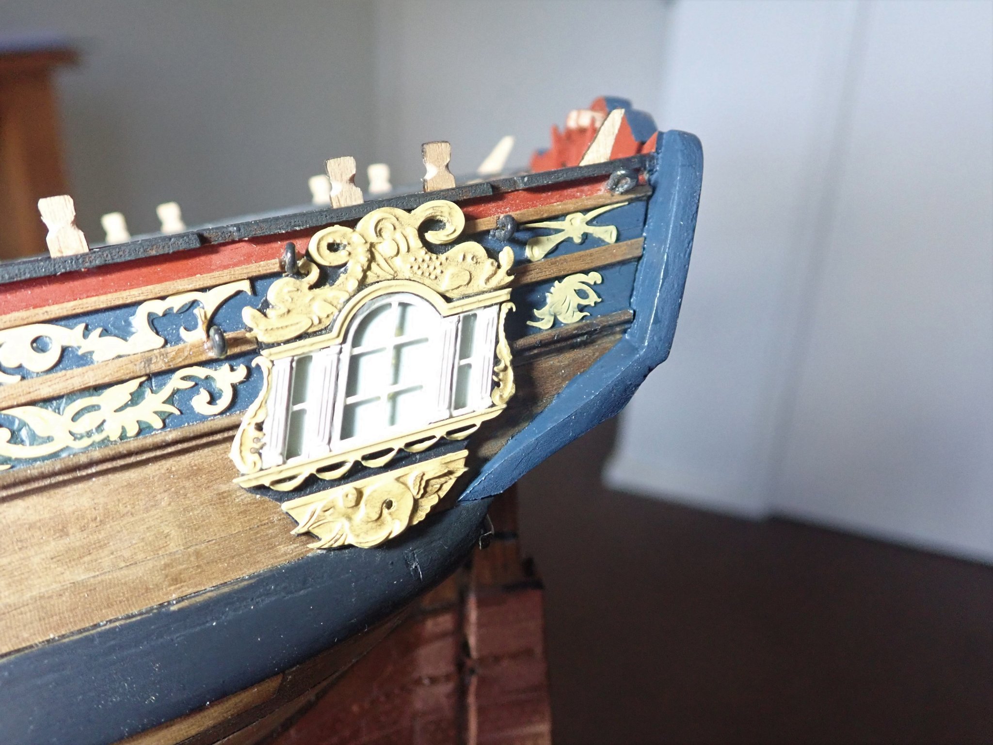
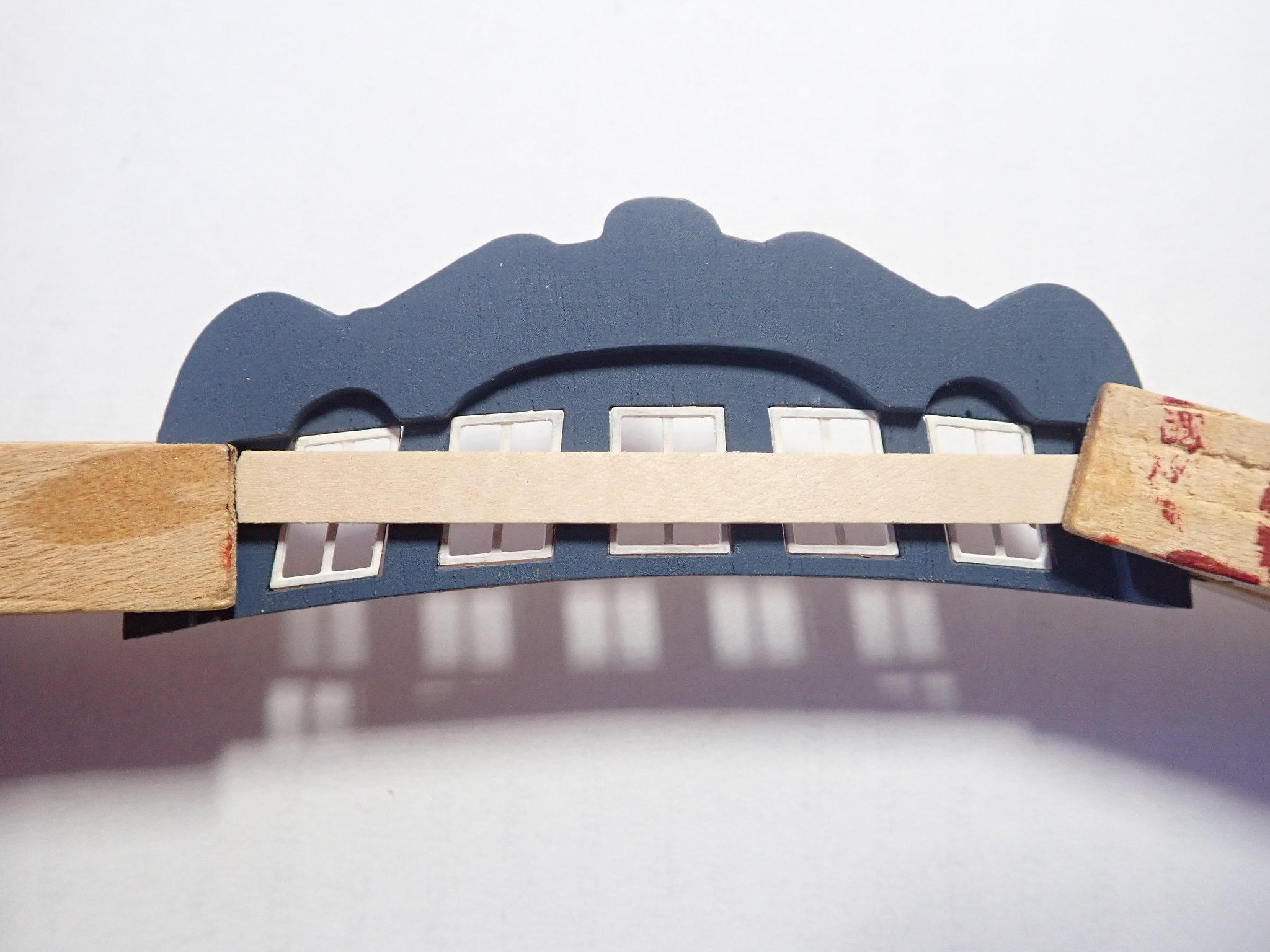
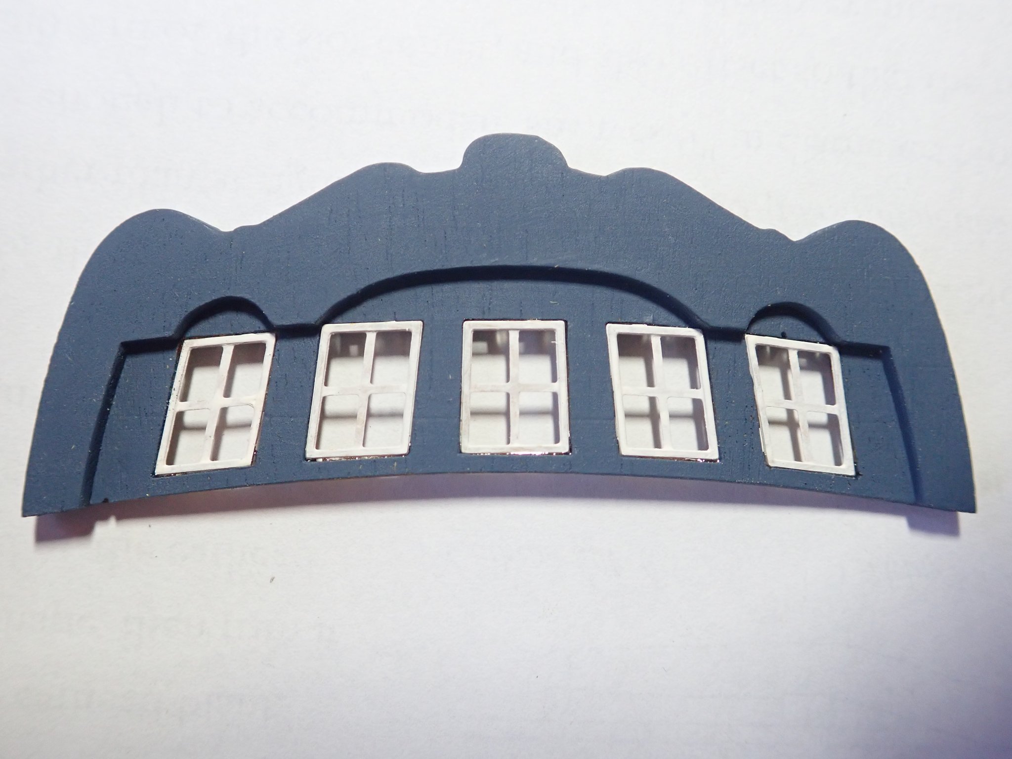
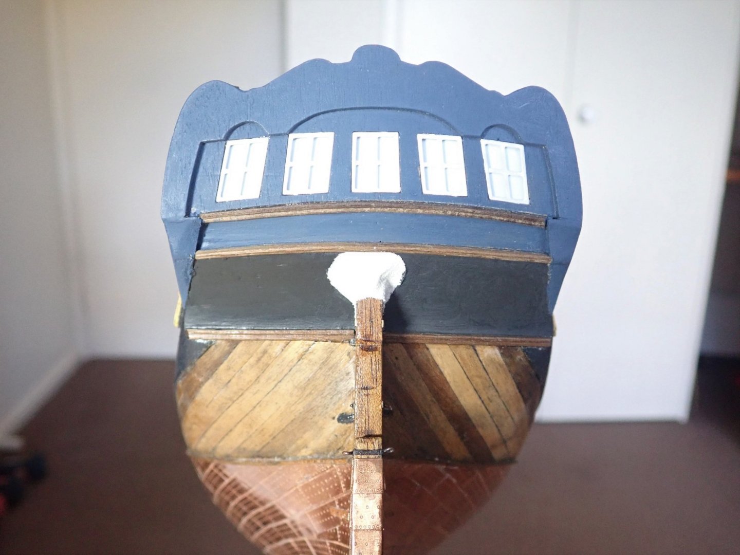
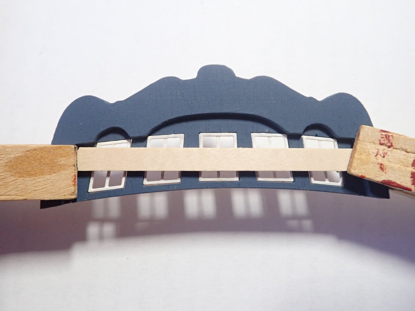
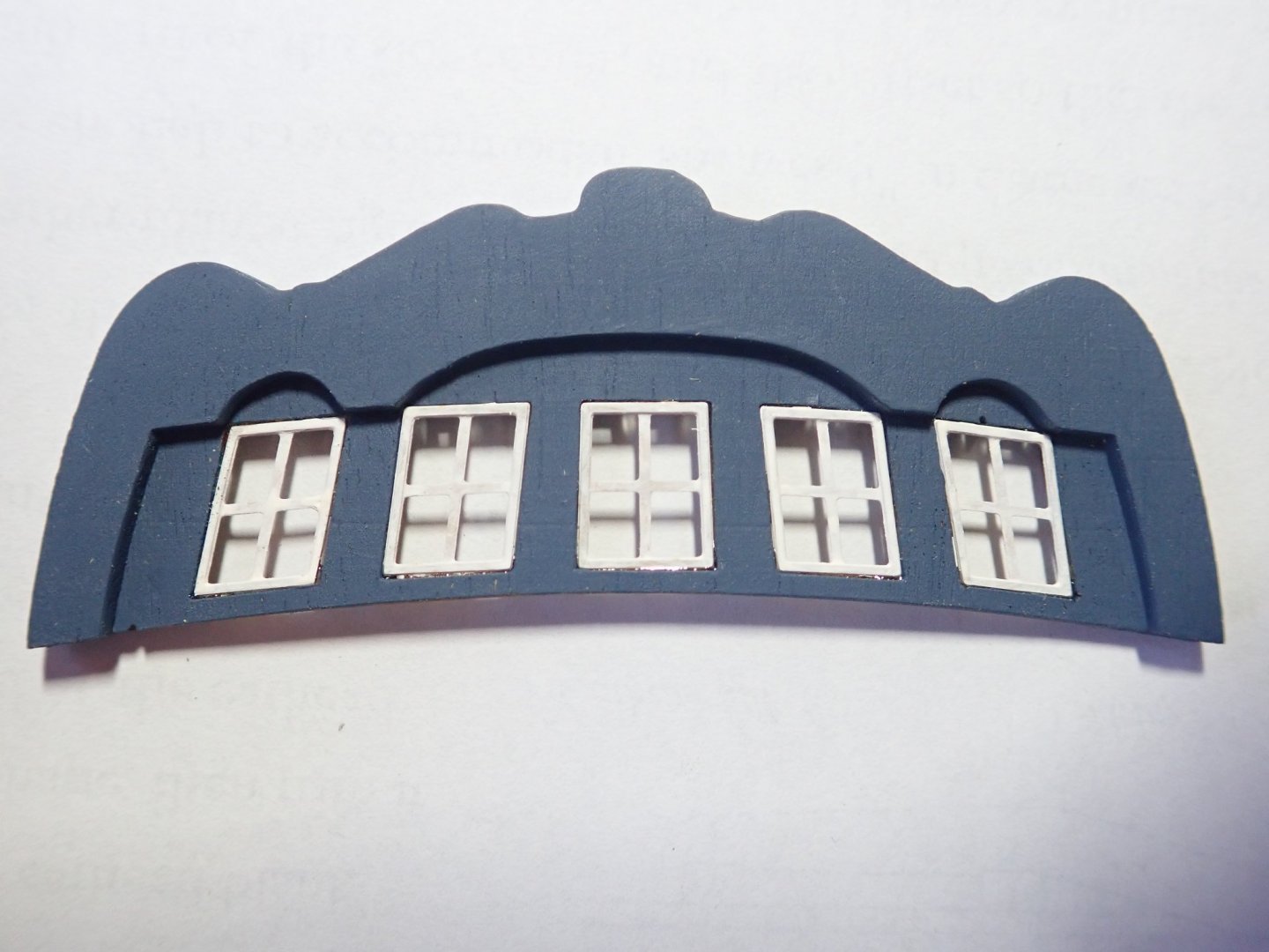
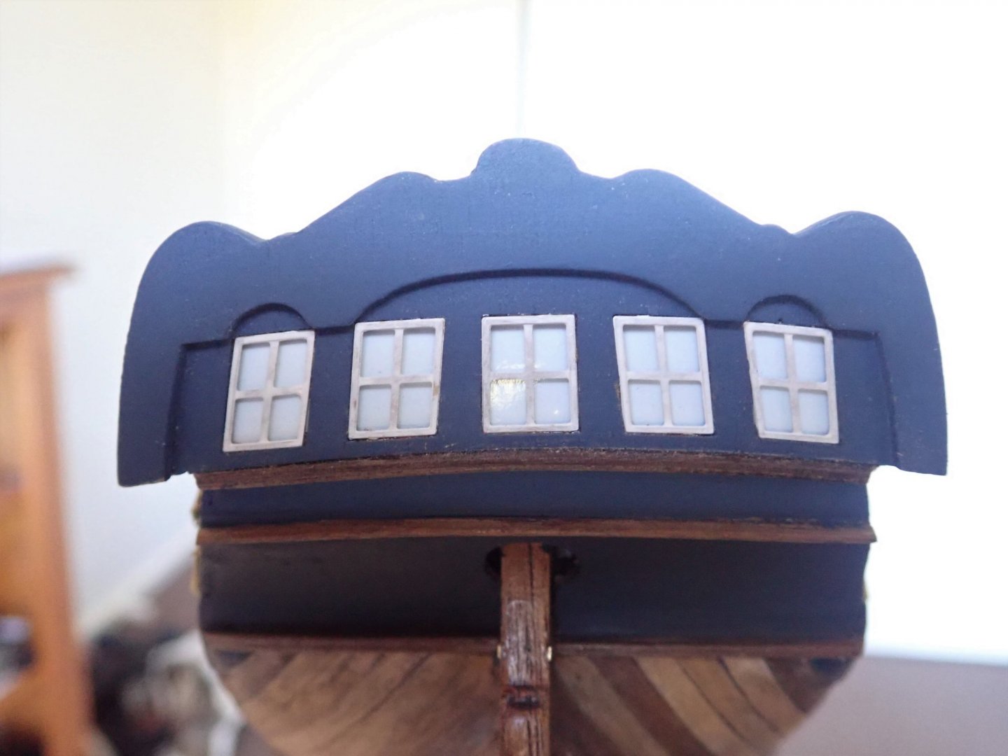
Thanks for the likes. A simpler binnacle than the one provided in the kit was made following advice from Blue Ensign and Greg Herbert - thanks guys.The photo shows it roughly in place on the deck.It will be finally fixed quite a bit later. The capping rail is made up of four laser-cut pieces that go on the fore and quarter decks, and in the waist, the instructions say to use 1.5mm thick strip here. When I offered up a section, it seemed to me to be too thick, so 1mm strip was used instead. Slots in the bulwarks for the catheads were cut before the capping rail was glued in place. The inboard end of the kit supplied catheads are at the wrong angle to allow them to fit under the capping rail and sit flush on the deck. While sanding a more correct angle, I broke one of the catheads and so had to make two new ones. Holes were drilled in the outboard ends to simulate the sheaves that would be there - the instructions do not mention these, nor do they mention cutting the slot first. It would certainly be tricky to cut the slots after the capping rail was in place, which is what the instructions say. The photo shows the kit supplied cathead on the left and the new one on the right. The catheads loosely in position, they will be removed for now and fastened sometime later. I have made a start on the fascia and tafferal at the stern. I prebent the tafferal then glued the fascia to it. I then added the windows to the tafferal. To ensure the PE window frames finished up flush with the outside of the tafferal, a piece of strip wood was held in position as shown in the photo. The frames were then inserted from the rear and gently pushed home against the strip. A thin bead of epoxy was run along the edges of the frames to hold them in place. As I did with the quarter lights, gloss pale blue paper was used to represent glazing of the windows. These were individually cut and a small amount of PVA used to glue them in place. The next job will be to do something about the very obvious gap under the lower, outboard ends of the tafferal. Cheers


- 104 replies
-
- 10
-
-
- pegasus
- victory models
- (and 2 more)