Egilman
-
Posts
4,375 -
Joined
-
Last visited
Content Type
Profiles
Forums
Gallery
Events
Everything posted by Egilman
-

Keeping my head in the game.....
Egilman replied to Egilman's topic in 3D-Printing and Laser-Cutting.
Thank you Brother! Well, it is off the beaten path, but welcome to the thread.... So far everything is going well, Doc is happy, Last scan showed no tumors and in 10 days I start another course of chemo... Prophylactic in nature to keep it from coming back since this type of cancer never goes away and could show up anywhere at any time... Year and a half in and I'm doing well they tell me, almost a third of the way to beating the average life expectancy of this... (5 years) God willing is all I can say.... I'll keep plugging away at something, like the title says keeping my head in the game....- 85 replies
-
- 10
-

-
P-51D Mustang by CDW - FINISHED - Dragon - 1:32 Scale
Egilman replied to CDW's topic in Non-ship/categorised builds
There's another guy that went one step further than just restoring them to flying condition... Paul Allen maintained a collection of warbirds, (a warbird is a plane that actually served in combat) that were not only restored to flying condition, but to original manufacturers specification as originally built... if they couldn't find an original part they went to the original part manufacturer or the current owner of the technical documentation, and had the part made using the original materials... Sometimes, they had to make the materials before they could make the part.... (the cloth covered wiring on the P-51 was a good example) all of the aircraft, (except for the Hurricane), are combat warbirds, and all of them are restored to original issued condition, and flyable... But of course it takes deep pockets for such, and with 30,000 million dollars to his credit (30 billion) he could afford it... The collection has been sold out of Mr Allen's estate, (his family didn't share his love of such things) and is being maintained by a 501C non profit corporation, created by one of the Sam Walton (Wal-Mart) heirs...... Flying Heritage -
P-51D Mustang by CDW - FINISHED - Dragon - 1:32 Scale
Egilman replied to CDW's topic in Non-ship/categorised builds
But it is something impossible to model... What he is talking about is the panel joints, yes in the mfg process, the panel joints were puttied to fill any gap, then smoothed to make an ultra smooth surface so the Laminar flow process would work to it's best advantage.... It's why you don't see it on any restored warbird and they polish up into seamless mirrors.... There isn't a modern kit out there that is going to require puttying the wing panel joints.... Besides the Aluminized paint the used to cover the putty polishes up almost like the metal itself does and a wartime bird didn't ever see any polish, cleaners yes but never polish... The only time you see a polished mirror shiny warbird is the airshow, never in theater... After looking at 10's of thousands of P-51 photos, reading the manufacturers manuals and the military reference manuals... Puttying the wings is something you can't model realistically.... Just my opinion as an avid P-51 lover and modeler... -
Keeping my head in the game.....
Egilman replied to Egilman's topic in 3D-Printing and Laser-Cutting.
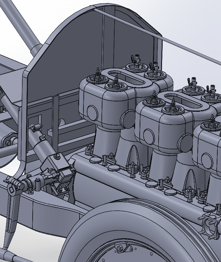
Thank you my friend, something to do while I get RL in order... Still recovering from the government actions that cost so much financially.... Currently working on the firewall.... And the reverse side.... It's complicated, a lot of other parts previously created have to mesh with it and it's not just one solid piece.... Closeup.... About to start version 2 of it, after I correct a few of the issues the other parts are creating... Anyway, onwards, eventually I'll get it sussed out....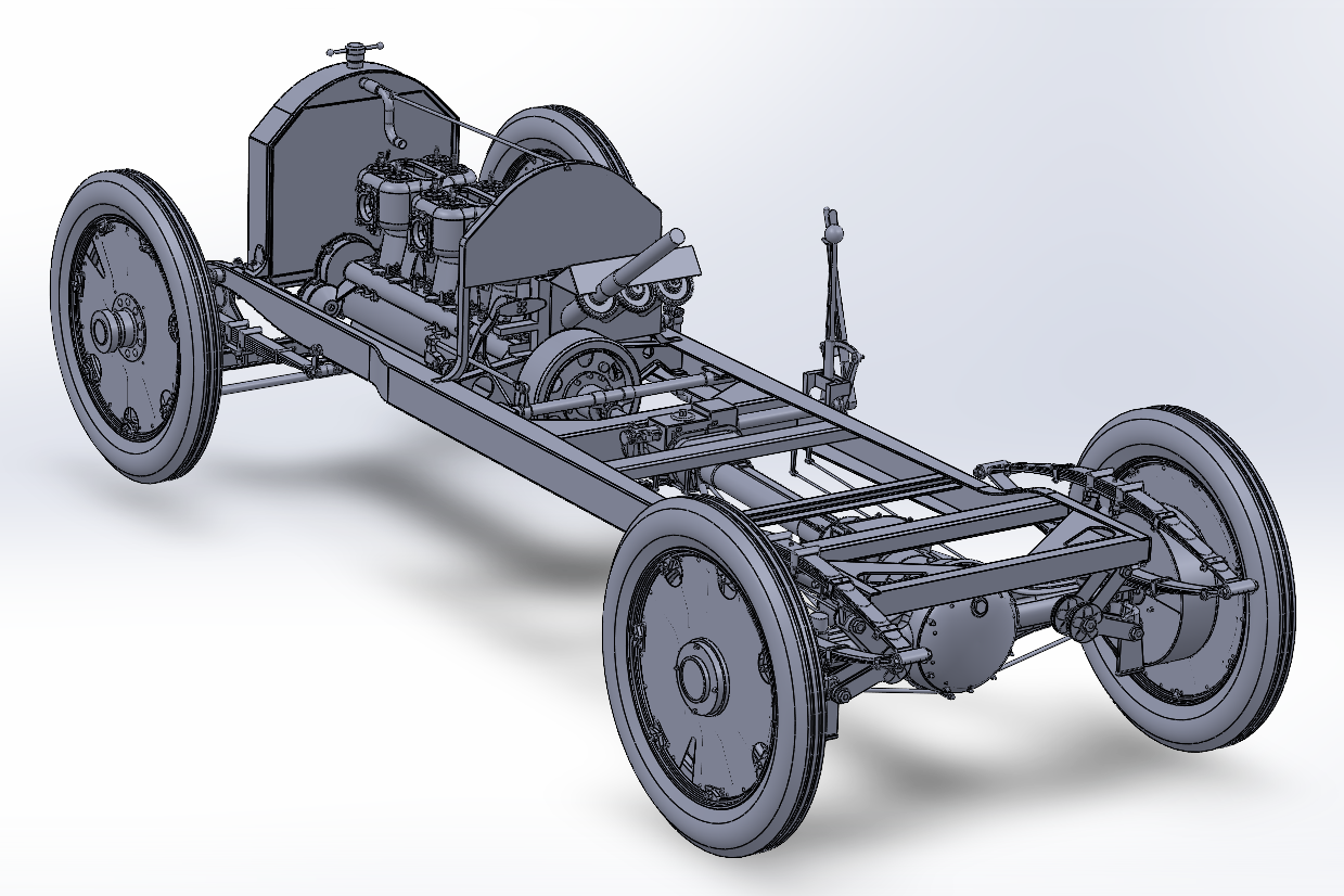
- 85 replies
-
- 10
-
-

-
Yep the last assault before the KGL gave it up... I always thought the French troops looked exhausted in that painting... That's why they lost.... The reduction of Le Haye Sainte, is one of the dramatic visions of heroism ever seen on the battlefield, on both sides...
-
P-51D Mustang by CDW - FINISHED - Dragon - 1:32 Scale
Egilman replied to CDW's topic in Non-ship/categorised builds
Yep, on all mustangs the panel around the exhaust was stainless steel.... And Yes, some of the Mustangs, (like the T-bolts), had camoed wings and bare metal fuselages... but for some reason pics are rare.... -
Yep Radio aerials are never taut, especially in the beginnings of wireless.... The copper wire was just plain too soft, they would break under their own weight if stretched too tight... By the time WWII came around they had switched to aluminum wire for aerials, much much stronger, they could actually pull them almost straight... I have a headache from trying to figure out how he did it without making a tangled mess...
-
It's a Whirly-bird? I'm in...
-
That's a pretty good rendition of the swell on a mild day on the North Sea.... (10 to 12ft) Now to duplicate the greyish black-blue of the water... Geese, a master at work... It's a sheer pleasure watching you do your thing brother...
-
It wasn't really that, it was the other.... {chuckle} there is a reason he had us shoveling out the milking barn.... He didn't warn us either, dad said it was the fastest way to permanently learn not to stand behind the cow....
-
My Great Uncle had a farm in West Burke VT. 40 some odd milk cows and a bull.... (learned not to stand around the back end as they were being milked, {chuckle}) They were very friendly, and always came in for milking in the morning.... The Bull had his own section of pasture and would stand about ten feet inside the fence and just stare at you, the look in his eye was terrifying.... We used to build forts in the hayloft from the bales.... it was a grand time in my life....
-
Excellent job!!! The depiction of a NE Normandy pasture scene is par excellence!!! And Yes, the livestock frequently got in the way....
-
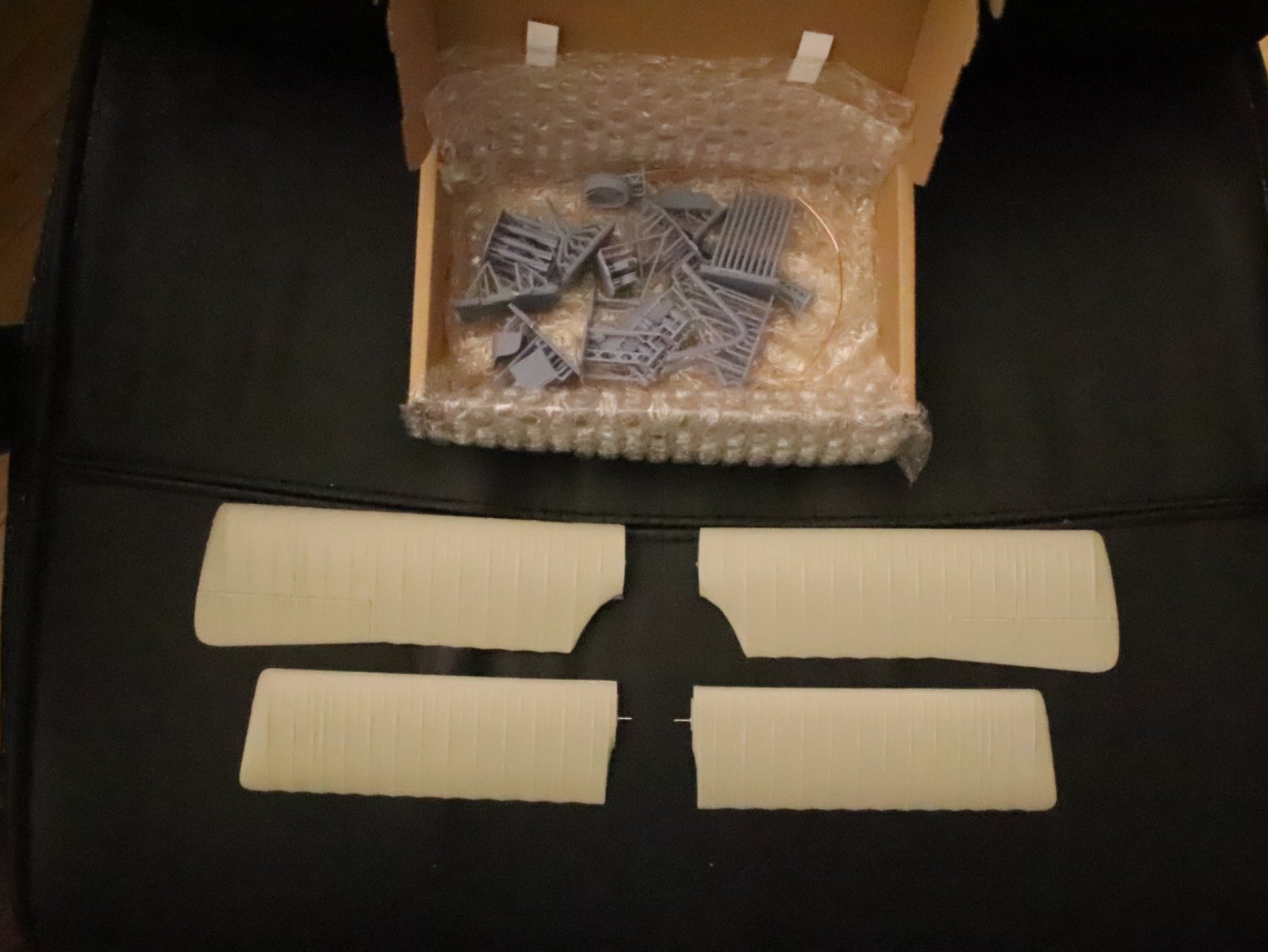
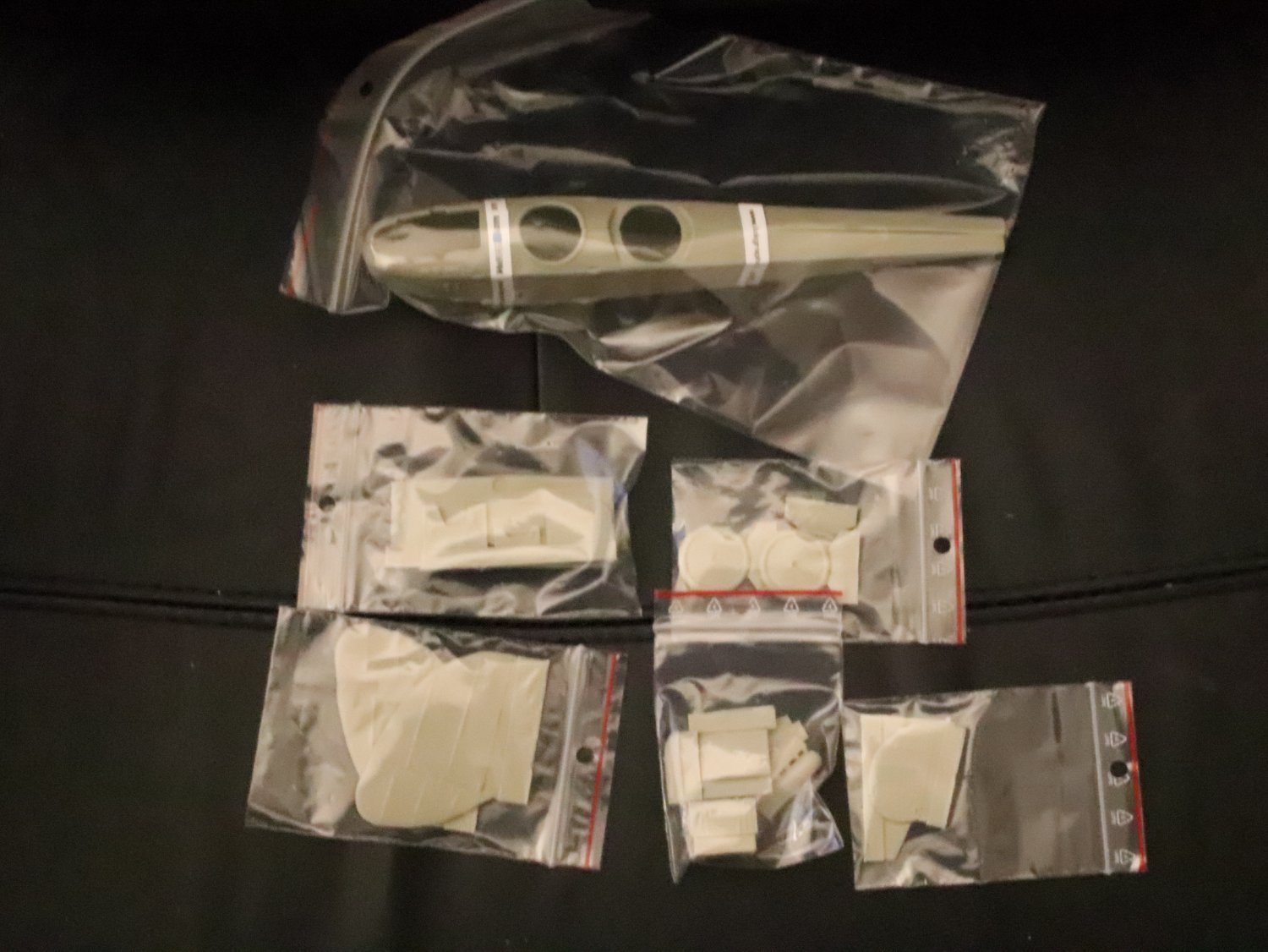
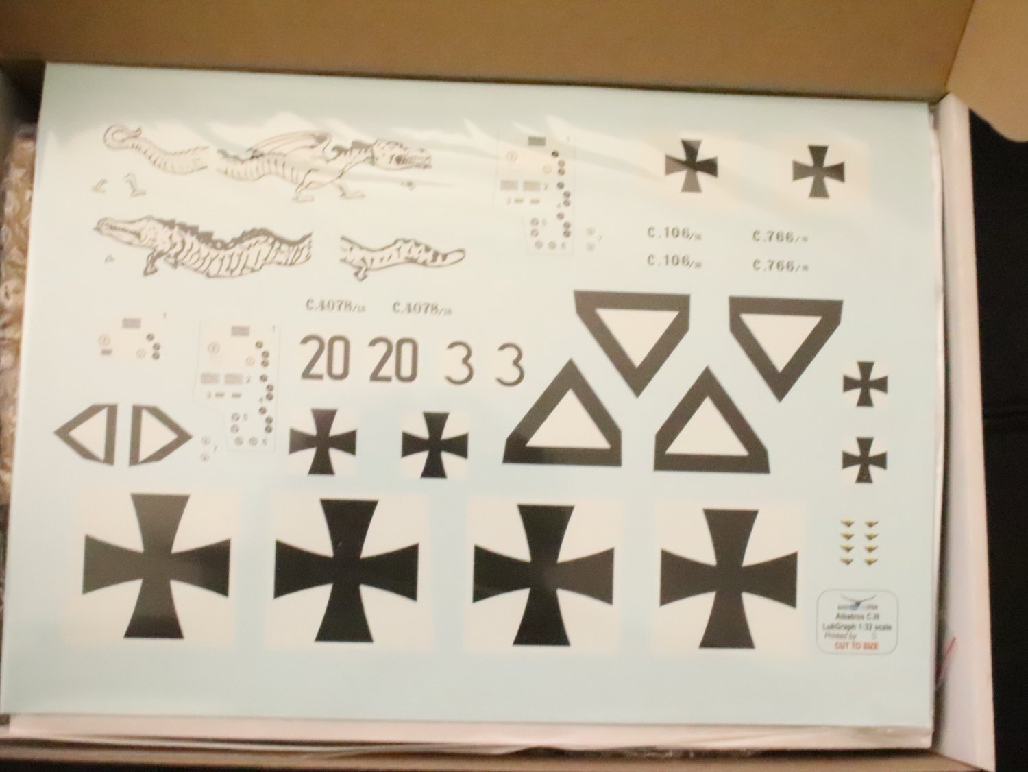
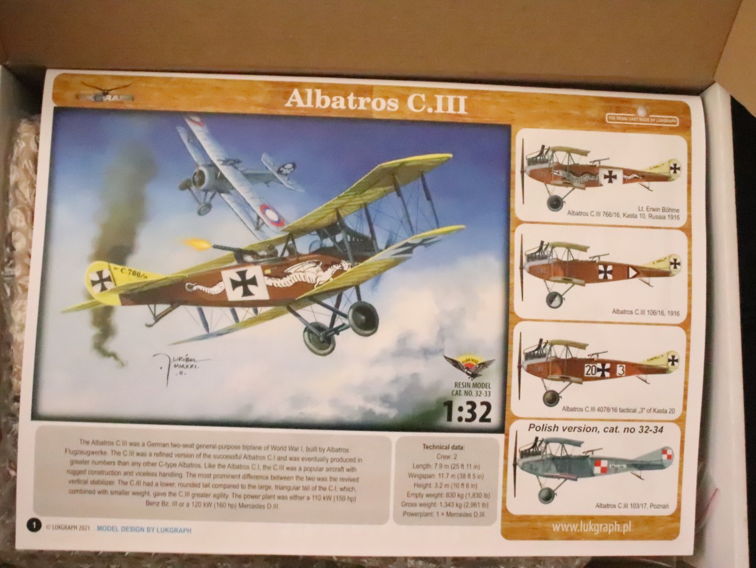
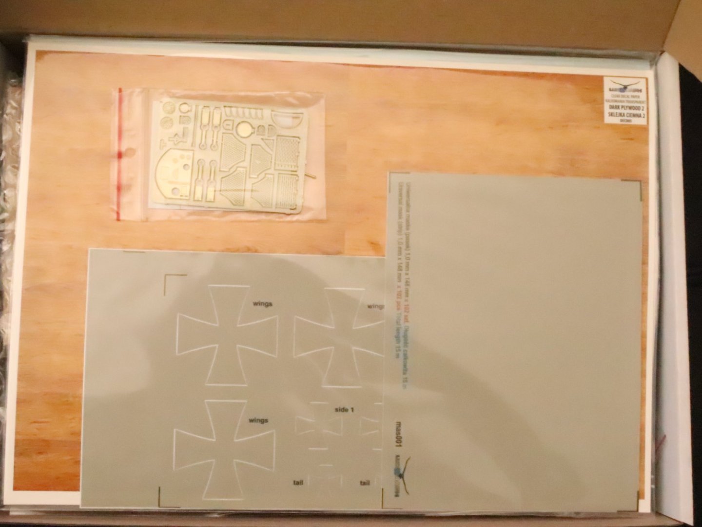
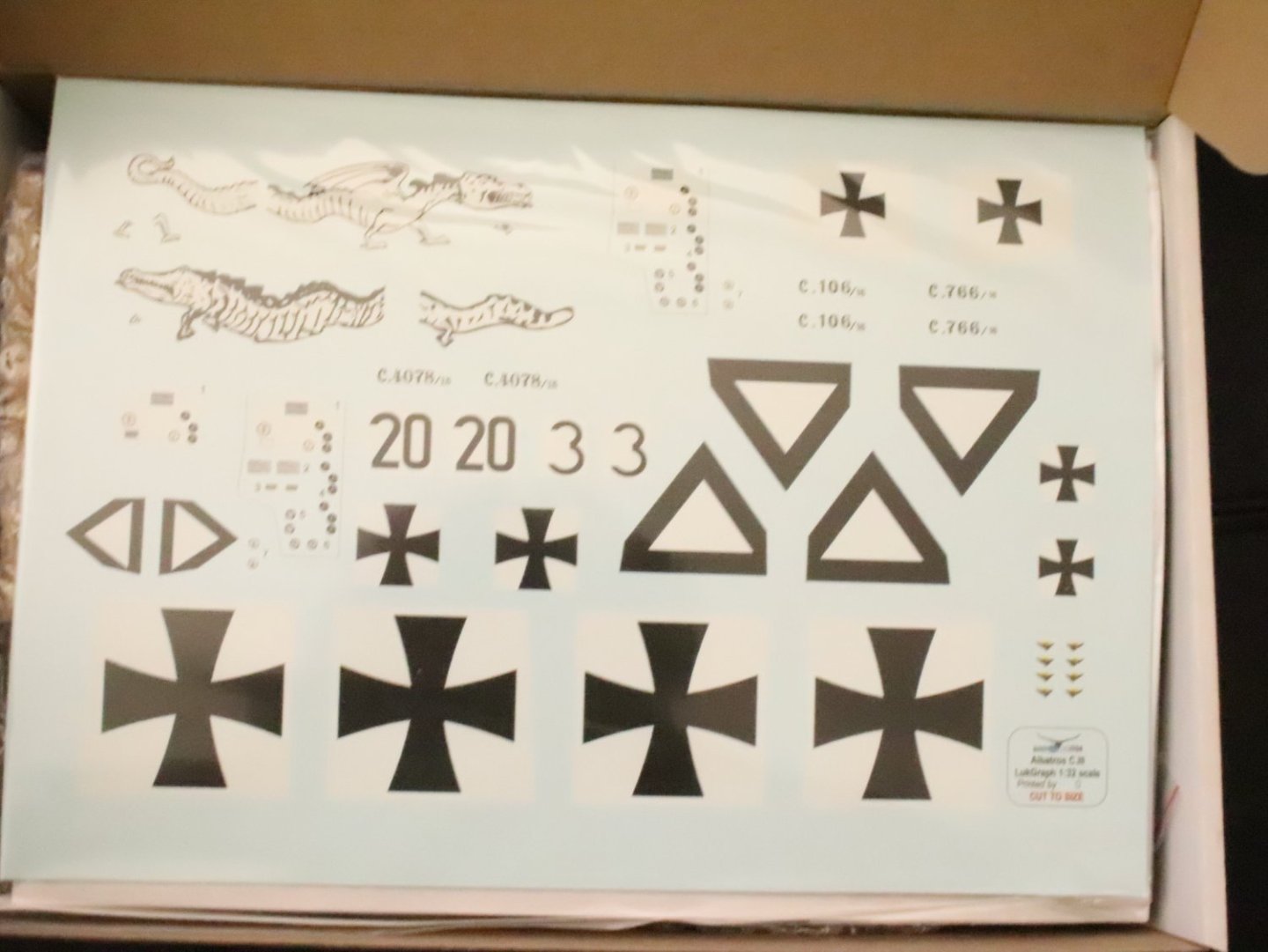
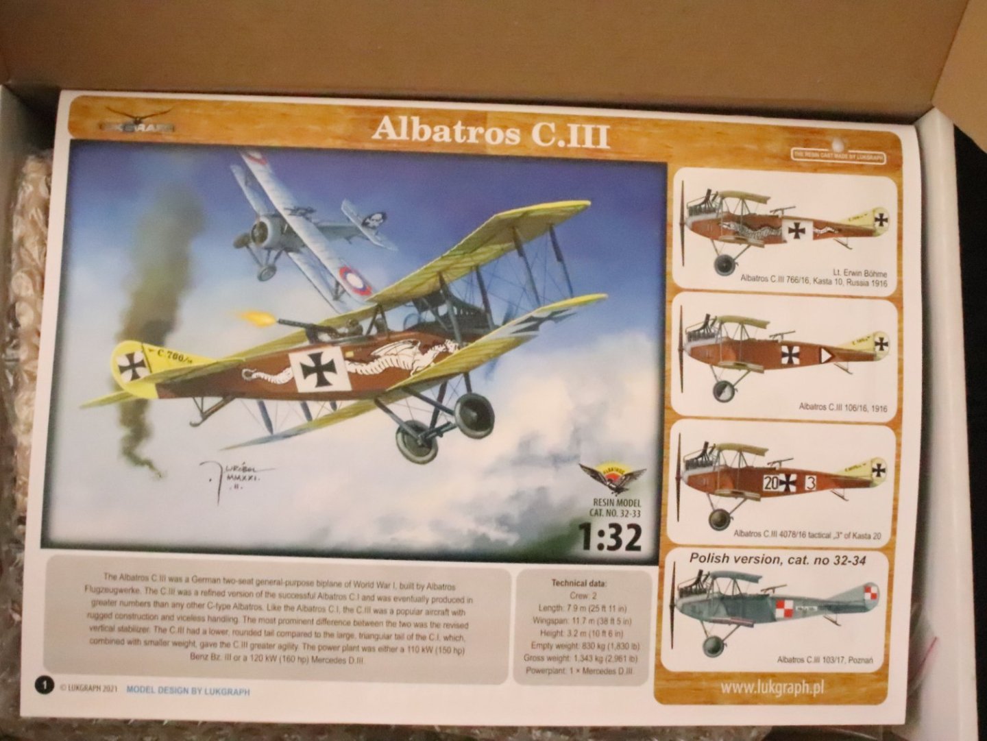
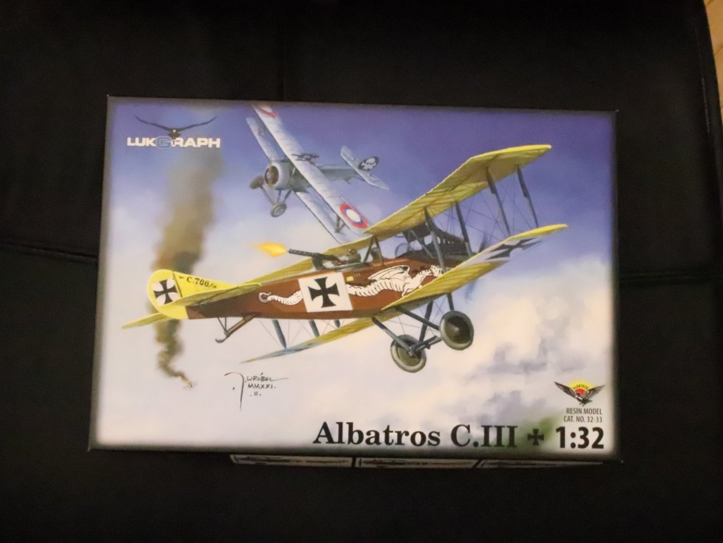
Yep, and subjects no one else has... I added some pics of the albatross to the previous posting, sorry for the de-rail Rob.... (probably should have done it in a PN) My apologies...
-
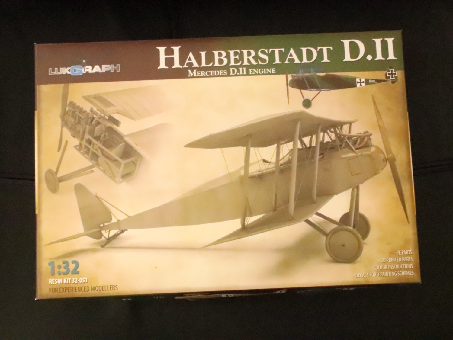
https://lukgraph.pl/ https://www.facebook.com/LukGraph/ They have an online store.... Best, (read cheapest) place to buy them... And they have all the extras (decals, both camo and plywood) as well... I have his Halberstadt D.II and Albatross C.III.... They are beautiful kits.... Send Lukasz a message, he's a great guy...


- 190 replies
-
- 10
-
-
-
P-51D Mustang by CDW - FINISHED - Dragon - 1:32 Scale
Egilman replied to CDW's topic in Non-ship/categorised builds
Yep, below 25,000ft... Amen brother.... Especially in bare metal..... -
P-51D Mustang by CDW - FINISHED - Dragon - 1:32 Scale
Egilman replied to CDW's topic in Non-ship/categorised builds
Actually yes it does, although he has slanted it towards the late war German Me 109 and the effort to keep it a viable combat aircraft, Daimler wasn't the first to use water injection and eventually methanol-water injection... Pratt & Whitney was.... In the R2800... It is what made the R2800 the engine it was... The water injection version entered production at the end of '42 and reached the front lines in mid '43... a full year before the first Me109K flew... As the initial production Corsairs and Hellcats came back for engine replacement they were upgraded to take the more powerful engine... By the end of the war all Corsairs and Hellcats were running on Water/Methanol injection engines... But it is interesting in it really explains what engine Knock is and what stops it.... (keeping combustion chamber temps down, while packing even more high octane fuel in) the easy way is to boost octane, but in wartime conditions that is not always available... Also something not said, the manifold boost and injection was not something used 100% of the time, it was used in emergencies only.... And yes even on the 109K, otherwise you would be rebuilding engines every two or three flights instead of every 50 flights.... Water injection was never incorporated into the Merlin engine in an operational aircraft to my knowledge... But I don't know everything {chuckle} and I'm sure those brothers that do will tell me quick... Excellent video my friend.... -
P-51D Mustang by CDW - FINISHED - Dragon - 1:32 Scale
Egilman replied to CDW's topic in Non-ship/categorised builds
Excellent Video Andy... Proves one thing, absolute speed is relative... Personally, Test aircraft should not be lumped in with service aircraft, and thankfully he didn't include the whole transonic arguments and the claims made in that genre... I tend to stick with combat aircraft.... Within the role they played in combat... Below 5,000ft the Tempest could walk an FW190, The Mustang couldn't do that... (in any configuration) Between 5-20,000ft they all flew in the same envelope and performed very similar.... Above 20,000ft there are only a few and of those only one saw significant combat.... And the Mustang, the Merlin powered Mustang, was that airplane.... In My Humble Opinion of course.... {chuckle} -
What you need to do brother is create driven pathways, places where the grass is trampled down along a vehicle track... The vehicles would always take a path repetitively and would wear down the grass eventually turning into mud paths.... Much like your mud puddle... They would be wider than the tires by two or three times, of course the grass on the airfield never got that high in the first place, but in the traveled areas and passage tracks it was always laying down... from being driven over...
-
P-51D Mustang by CDW - FINISHED - Dragon - 1:32 Scale
Egilman replied to CDW's topic in Non-ship/categorised builds
Yep the Vaunted Mustang.... The equal of any airplane in the sky below 18,000ft but she really showed her props above 20,000..... Nothing could outrun her or out maneuver her in the high sky... It took a jet propelled aircraft (Me262) to finally surpass her capabilities... After the war was over the USAF retired all other fighter aircraft in favor of her.... She wasn't downgraded until the F-80 Shooting Star was accepted into service.... She is still to this day the hottest propeller driven aircraft in the sky... (and a damn fine looking girl to boot) -
Keeping my head in the game.....
Egilman replied to Egilman's topic in 3D-Printing and Laser-Cutting.
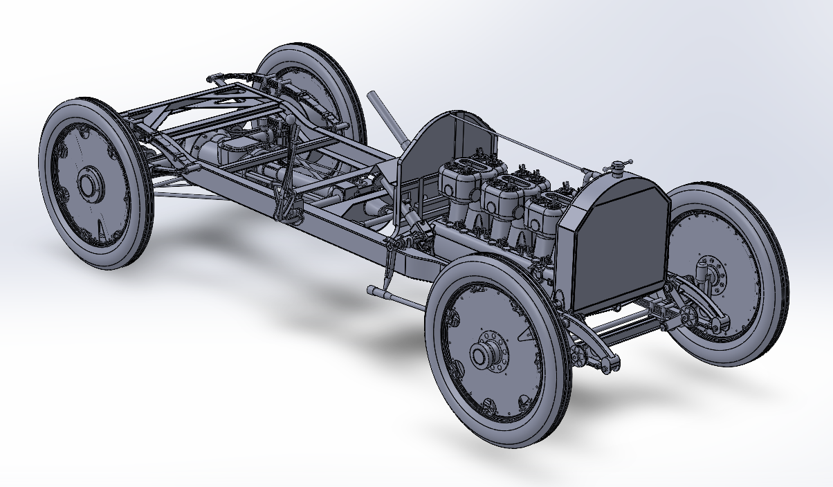
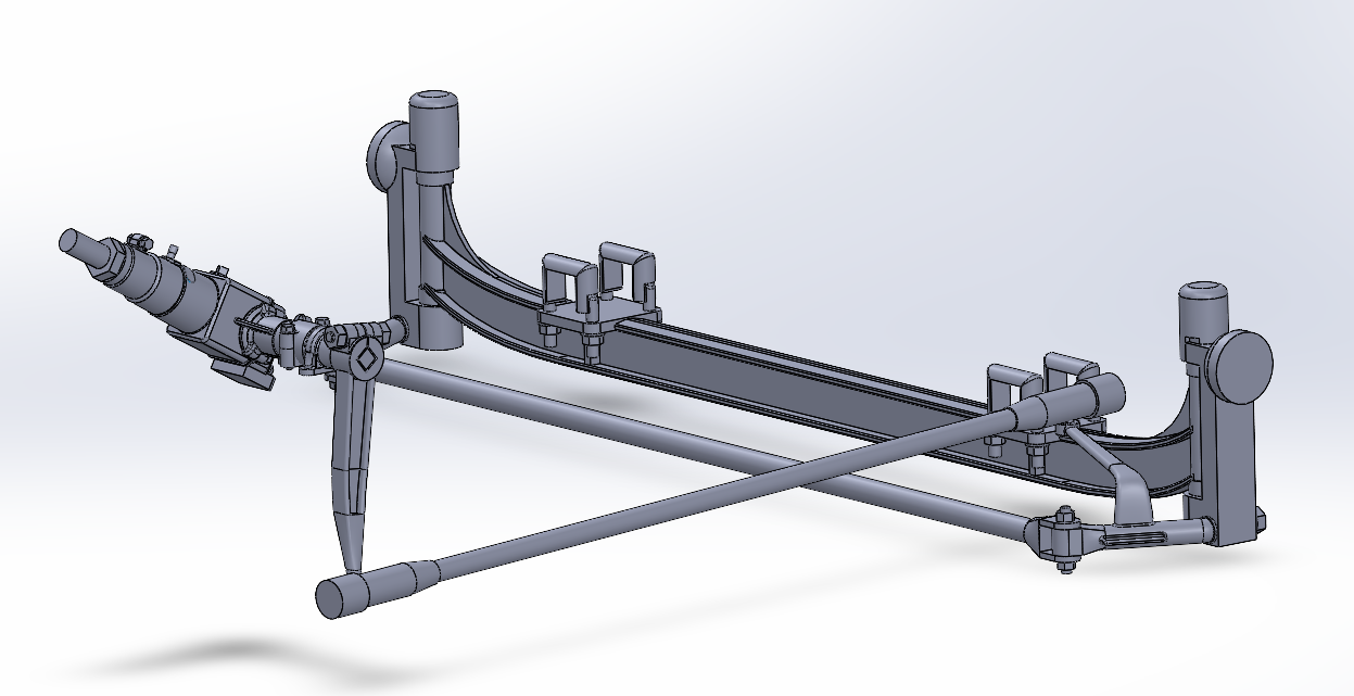
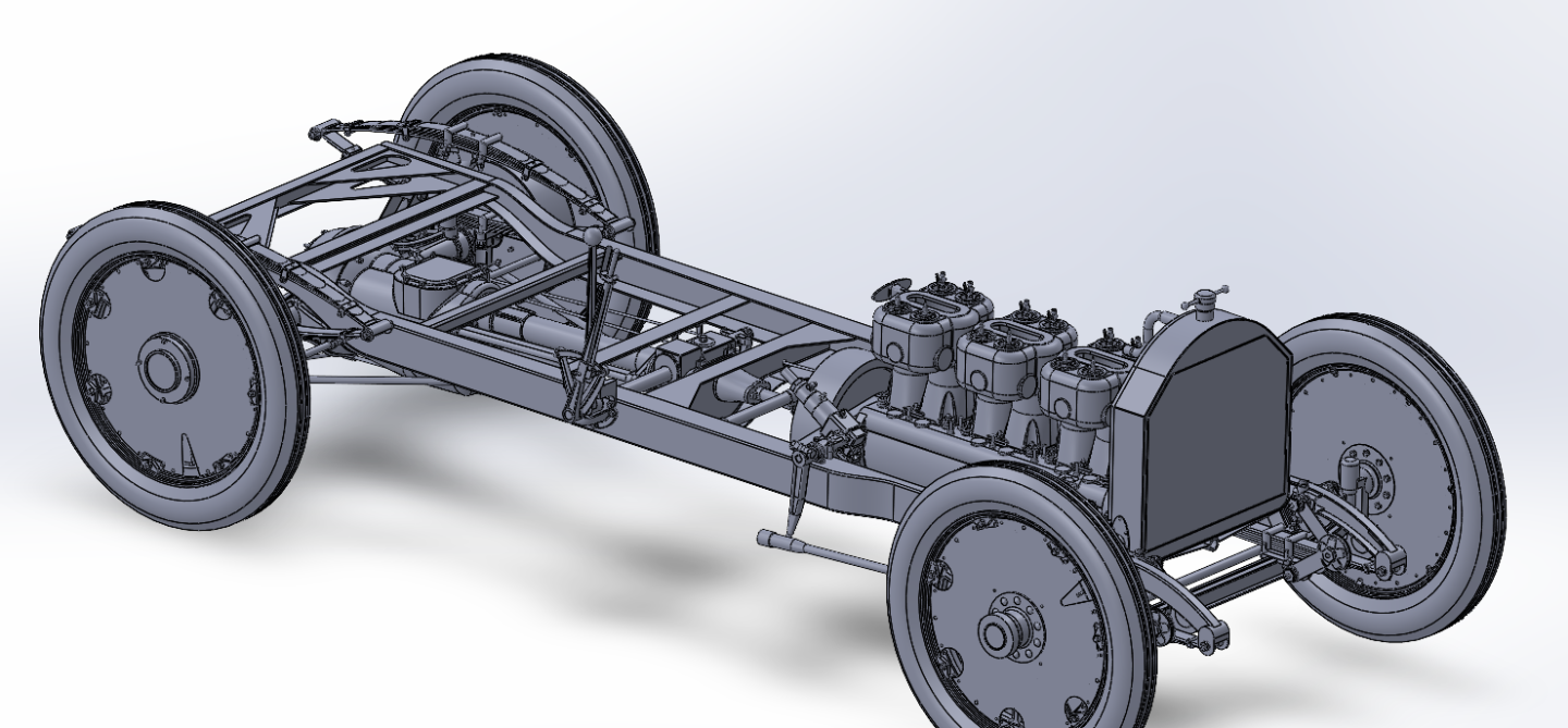
Another update... Steering gear is basically done... Some minor details to add.. And might need a bit of tweaking once the firewall is built but it's basic design is complete... Reverse angle view... And an overall right side 3/4 view.... We are getting closer to actually building something... {chuckle} I guess the firewall is next.... then I can adjust the gear box to it's final angle and install a steering wheel.... Anyways, the journey continues.... Onwards...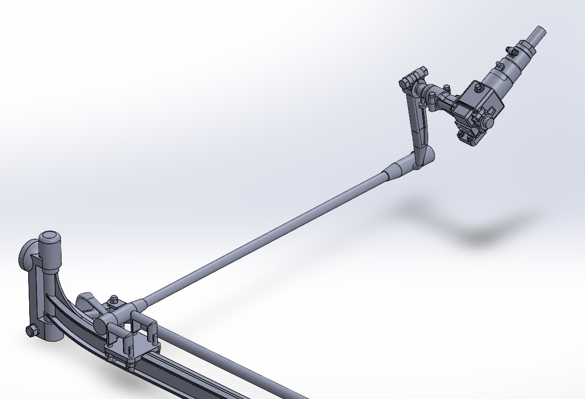
- 85 replies
-
- 10
-
-
Krupp 420mm Big Bertha by Haliburton - Takom - 1/35
Egilman replied to Haliburton's topic in Non-ship/categorised builds
Yep, History is replete with them, all eras, all societies..... It's the reason for Ike's famous piece of advice to Jack before Jack's inauguration, "beware the military-industrial complex"..... Play ball or you don't survive... -
Good Thinking, The Admiral said in passing that the solution was simple, it's just like tailoring a pair of pants or a skirt, when you need to make it larger you add a dart in the seam.... Well thought out my friend....
-
Krupp 420mm Big Bertha by Haliburton - Takom - 1/35
Egilman replied to Haliburton's topic in Non-ship/categorised builds
Yes they officially made railcars, but in reality the factory was "sold" to Bofors, and they continued to make guns under the Bofors name until about 1934 when they finally bought themselves out of it and a year later bought Bofors itself... Krupp was one of the most powerful industrialists in the world like Ford, Benz, Messerschmitt, Westinghouse, DuPont and several others... The normal rule of law doesn't apply to them... -
Issues like this is why I gave up on paper modeling.... Plenty of ways to fix this type of thing, but it's next to impossible once the skin is glued in place.... And you generally don't find this type of stuff until it is in place... Halinski's can be a challenge... Absolutely gorgeous when they go together correctly, frustrating fire lighters when they don't....