
HOLIDAY DONATION DRIVE - SUPPORT MSW - DO YOUR PART TO KEEP THIS GREAT FORUM GOING! (89 donations so far out of 49,000 members - C'mon guys!)
×


Egilman
-
Posts
4,377 -
Joined
-
Last visited
Content Type
Profiles
Forums
Gallery
Events
Everything posted by Egilman
-
 Yeah he's got it right for the cockpit portion only, somewhere between the cockpit and tail empennage, the cable will cross within the rear fuselage giving the proper direction to the elevator...
 -
The X1C and it's clones are a tool... fire and forget, load your file and print right out of the box... They are so good that both Anycubic and Prusa cloned it... It's the future of FDM... Resin still has it's place, but for some things FDM is now the turn to....... This is an excellent project YES, and I don't want to take it off course, if you want to discuss it, hit me up with a PN brother... Gladly share what I know... EG
-
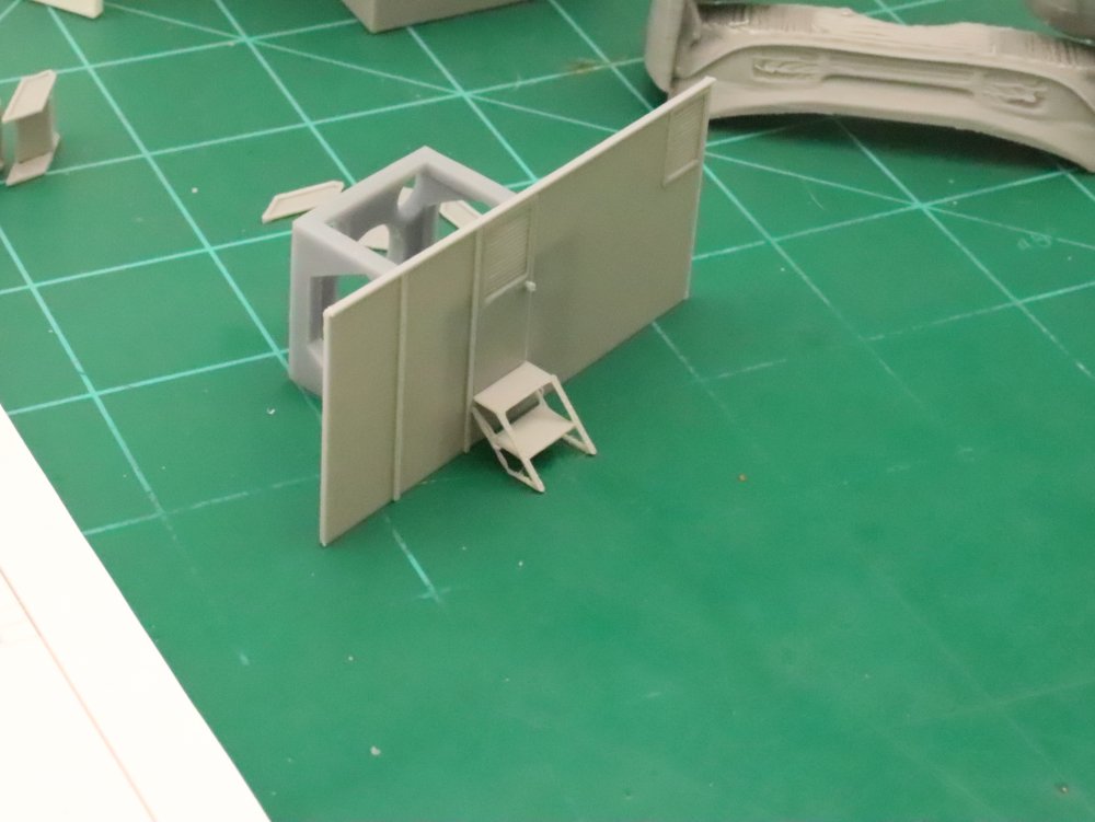
Ron, Brother, FDM printing has come a long way in the last few years... My X1C will produce parts that are just as smooth as most Resin printers... I suspect the Clones by Anycubic and Prusa will as well... I've actually gotten bead lines from the X1C at .007" off the build plate... Structural parts like he's proposing are no longer the private purview of SLA printers, they can be readily printed on a filament printer.... That's at 1/72 scale from a Bambu labs X1C.... That part in the upper right corner of the pic is the cowling section of the nose part for a '77 Pontiac Freeway Enforcer (Buford T Justice's car) printed off the X1C at 1/25th scale in ABS... Resin isn't the only option for fine details anymore...
-
I love it when manufacturers think they are doing a good job when they take the time to engineer an instrument panel that looks decent, then provide a single cover decal to put over a three or four level surface... Never gonna happen without cutting up the decal, and this plane had a grey interior with black faced instruments which will force you to cut up the decal to get it to look right... (or even attempt it) Roden isn't the only one to do this... And I usually chuck the decal and go straight to paint... I don't know if there is any aftermarket instrument panels for this model or aircraft, probably not given the obscurity of the subject... So I would agree with going straight to paint, the panel itself looks great, a fine piece of molding.... EG
-
Hey Dennis!! GOOD to see ya back!!! And with another great build as well... WE missed ya! Happy to see that you made it through the travails... The boy can build can't he..... {giggle}
-
Oh my pleasure, it is what we are here for.... EG
-
The Continental IO-360, has a steel crankcase, and steel sleeved aluminum finned Cylinders and Heads... The yellowish finish on the engine is the anodizing used to preserve and protect the parts from corrosion... and as you can see it doesn't last forever... Here is a link to the Maintenance and Overhaul manual on this engine... (scribd link) Looking good will be following...
-
Hold down weight and vibration damping...
-
Here's the Indiana Harbor Belt "O" scale (1/48 scale) 0-8-0 for sale... And, Casey Jones AHM O Scale Cannon Ball Express Locomotive Kit 4-6-0 for sale... (27 watchers on it, they don't last long) Both are reasonably priced.... EG
-
Me, I'm lusting after the Ferrari 330p4 or 412p both were upgraded 330p3's the only difference was the 330p4 had a fuel injected engine rather than carbs and the 412p was the North American Team version, otherwise identical...
-
He wasn't actually in the West German Luftwaffe, they wanted him but the US Airforce sent word thru NATO representatives that he was unacceptable... The Germans could have chosen him anyway, but decided not to... It is the only appointment of WWII Luftwaffe officers that was interfered with by the new NATO, (read US hierarchy) This was due to alleged sympathies with neo-nazi organizations... He became a consultant to the Argentine Airforce of Juan Peron.... Eventually returning to Germany and starting a consulting organization which eventually gained contracts with the West German Luftwaffe... He never held a military rank after WWII... He eventually became good friends with Douglas Bader and godfather to Bader's son.... And unofficially friends with many US Air Force officers, He was an Anti Nazi, both Goering and Himmler tried to get him imprisoned or assassinated during the war... He was an affable chap, very easy to get along with and one of the greatest fighter pilots to ever fly... An ace in both propeller fighters and jets... While with the Argentinian AF he flew the Gloster Meteor, he was reported to have said that if the Germans had anything like the meteor engine in the Me-262 it would have been the greatest fighter jet of all time....
-
Search the internet first your looking for names like Glardon-Vallorbe... Corradi... Esslinger Grobet... Ebay isn't the place to look brother... The real deal.... (but pricey, but then you know as we all do, you get what you pay for) EG
-
Look at any of my builds and you see the same identical thing... We all have that tendency brother...
-
This is one of the things that scares me with MFH kits, they are beautifully made yes, meticulous details and assemble much like the real thing... But if they are off in any way in the first sections, it shows up way down the line... The interference issue seen here would have easily been handled with shaving the engine parts to lower the carb and intake profile just a few portions of a mm... Then it would make it an easier job to shave the bonnet to fit... I know back seat driver and monday morning quarterbacking... But I have faith that You will get it right my friend... You skills are far past anything I've seen before...
-
Yep there is so much stealing of others customers that it is getting very hard to find some items online, like microfiles... And certain other tools of the trade... I still get my Micro-Mark catalogue in the mail, but seldom buy from them anymore, just about everything they have on specialty tools is sourced from somewhere else, low quality and almost twice as expensive as the original manufacturer... to me IMHO, they have become the Harbor Freight of online tool buying... Be very careful of what you order from them...
-
Jewelers micro file set... https://www.amazon.com/Micro-Mark-81845-12-piece-Micro-File/dp/B0058EDUM8/ref=asc_df_B0058EDUM8?mcid=71d1bde401673526aea980d2055a9046&hvocijid=16478961440123805471-B0058EDUM8-&hvexpln=73&tag=hyprod-20&linkCode=df0&hvadid=721245378154&hvpos=&hvnetw=g&hvrand=16478961440123805471&hvpone=&hvptwo=&hvqmt=&hvdev=c&hvdvcmdl=&hvlocint=&hvlocphy=9033430&hvtargid=pla-2281435178298&psc=1 It's a start, but do your research, there are many mfgr's labeling their needle files as micro files... make sure of what your getting..
-
I remember acquiring my two MFH kits, both of Sato's winning rides in the Indy 500... Pricy, pricy, hard to find... Definitely would have been cheaper off the website but they were both out of production with no though of re-release... I was lucky to find them...
-
Glad to hear that MFH is one of the few companies in this business that take CS seriously... Excellent to hear... Hopefully some of the others will take heed....
-
Doesn't matter brother, we'll still be here... (giggle)
-
Fokker D.VI by ccoyle - MPModel - 1/33 - CARD - TERMINATED
Egilman replied to ccoyle's topic in Non-ship/categorised builds
I can make a suggestion, It's a vent, a scoop facing backwards is a vent, it draws air out of the compartment it is open to... So, the rear will be open... And given the colored part of the fuselage where this vent is open I would say is the lower part of the vent where it meets the fuselage and the two parts are the inner and outer portions that cover the white section of the fuselage part... The smaller part glues to the larger outer part which is then bent to the appropriate shape and glued over the white section on the fuselage... It creates either a vent or a fairing, and yes some of these planes had a gauge of some type on the upper fuselage faired over, where the pilot could read it Only way it makes sense to me... -
Fokker D.VI by ccoyle - MPModel - 1/33 - CARD - TERMINATED
Egilman replied to ccoyle's topic in Non-ship/categorised builds
You said it brother, the gift that keeps on giving.... It seems like when one part of the process has these type of issues, ALL parts of the process develop the same or similar issues... {chuckle} You know it will pass with time... Keep on keeping on my friend... -
Fokker D.VI by ccoyle - MPModel - 1/33 - CARD - TERMINATED
Egilman replied to ccoyle's topic in Non-ship/categorised builds
...... For a designer, there is no excuse one can make... wrong is wrong.... Sad Very Sad... -
I'm still here brother... {chuckle}
-
It's been my experience that Tamiya primers work best on everything... (Even UHMW plastic which is notorious for NOTHING sticking to it) Standard Grey or Fine white is the best primer for high detail work... But use the Fine White when doing the bright colors, a lot better Color consistency, especially for the reds and yellows...
-
Skoda 30.5 cm 1911 Cannon by RGL - - WIP3D - 1/35
Egilman replied to RGL's topic in Non-ship/categorised builds
Resin has been around since since the middle ages, as what we today call plastics since the mid 30's, the funny thing is I'm still waiting for any scientist to show everyone the person that died from contact with Resins... That person just doesn't exist.... There are thousands of compounds that are a world sight more hazardous than resin in common usage every day... Breathing dust? I don't want to breath sawdust, but sawdust is not considered a health risk, but it is more carcinogenic that photopolymer resin... It's a simple fact, we can live in fear of things not likely to be proven, or we can live out lives taking normal precautions without fear... Brother, build those models, they are less dangerous than the margarine you spread on your toast... I did the research, I got the MSDS's pages... Heck they ship it around the world by the ton in bulk without any conditions, you want your kids to learn mold-making? Hobby Lobby sells it as stem kits to teach science and engineering to 10 year olds... How long are we going to live in fear? How long are we going to let the few dictate to the many? WE all learned a long time ago we can't believe everything we are told cause we aren't told all that much... And someone drops the words "Cancer causing" (without a shred of real proof mind you) on a material and everyone starts shivering in their diapers... Sorry, but I get more and more disgusted with the blind fear I see exhibited each day wondering when the world is going to wake up.... Getting off the high horse now brothers, just needed to vent a bit... 2.5 year cancer survivor here, I am working with photopolymer resins each and every day, there is no Oncologist in existence that can tell me that the resins caused my cancer, and that is from the HORSES MOUTH.... Build the models, the resin will not get you, but the paint you color them with will... EG

