
Strelok
-
Posts
95 -
Joined
-
Last visited
Content Type
Profiles
Forums
Gallery
Events
Posts posted by Strelok
-
-
I took a look at the book and unfortunately, the rudder/tiller construction is mentioned in the equipment-chapter. According to my thesis, this would correspond with Vol. 4 of the book series. Unfortunately this volume is either not available anymore OR it is not yet published. 😕
-
Yes, there is one book covering everything, which I have, too. But I found a series of books on amazon, where he goes into each chapter in more depth. So there are three volumes of around 160 pages each about boats and small vessels or two volumes of 220 pages each about building the hull. Therefore the single book covering everything acts like a summary for the series.
I think, as the volumes of the series seem to be in the same order as the chapters in his book, I think I should take a look, where Mondfeld talks about rudder- and tiller-constructions and buy the book, that deepens the corresponding chapter
-
I think abou getting the volumes 5.1 - 5.3 of zu Mondfeld's "Encyclopedia of building historical scale model ships" (Enzyklpädie des Historischen Schiffsmodellbaus), which are about boats and small vessels or vol. 8 about ropes, tackles and rigging 🤔
Does anybody know, if they are - in this particular case - of good use?
-
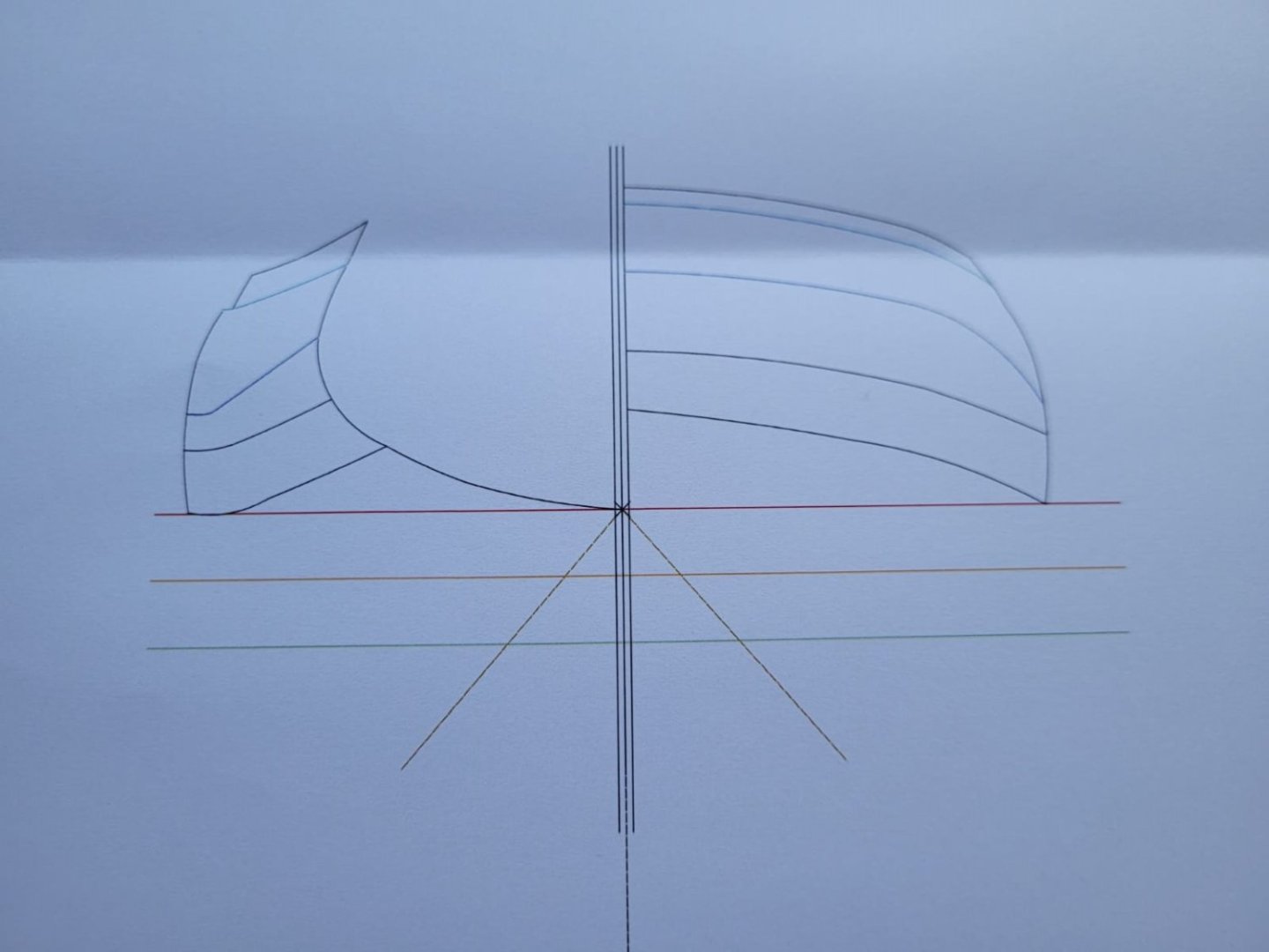
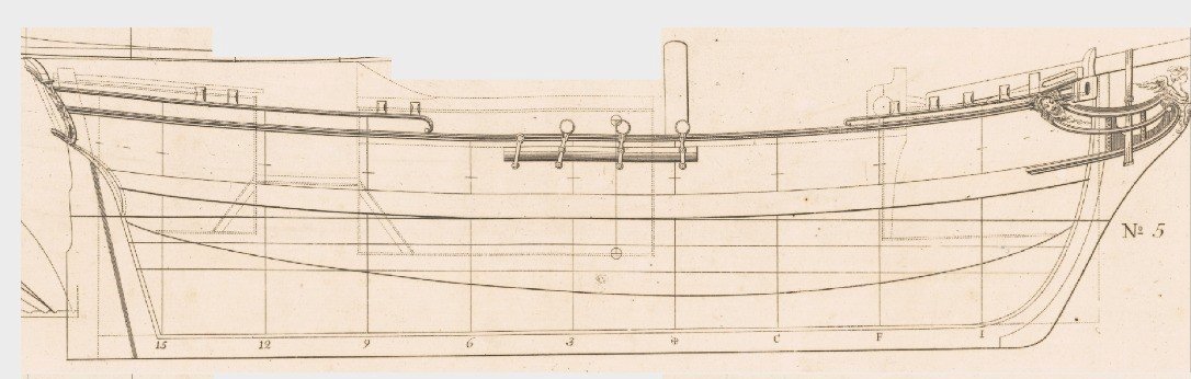
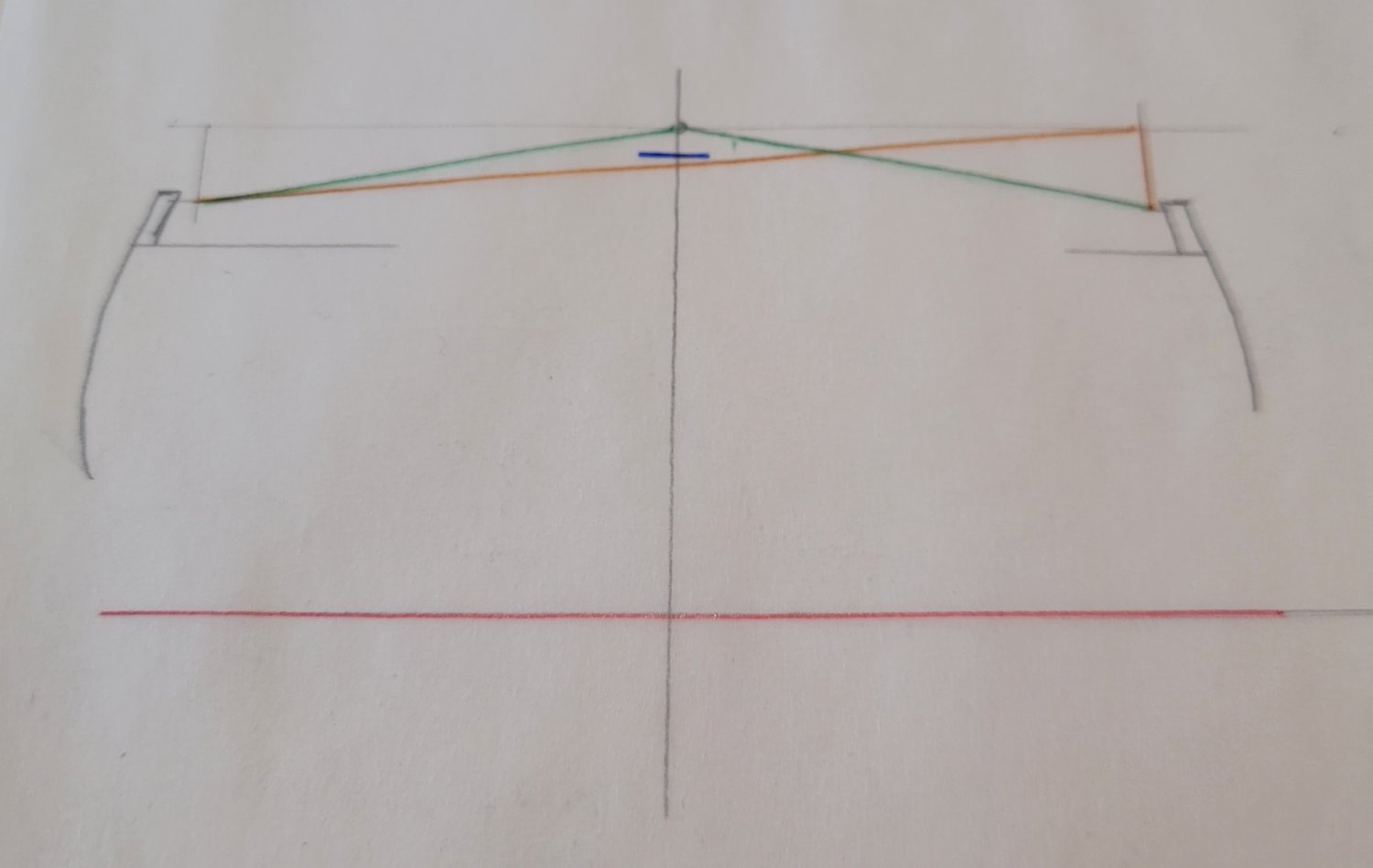
I just made a sketch concerning the tackles.
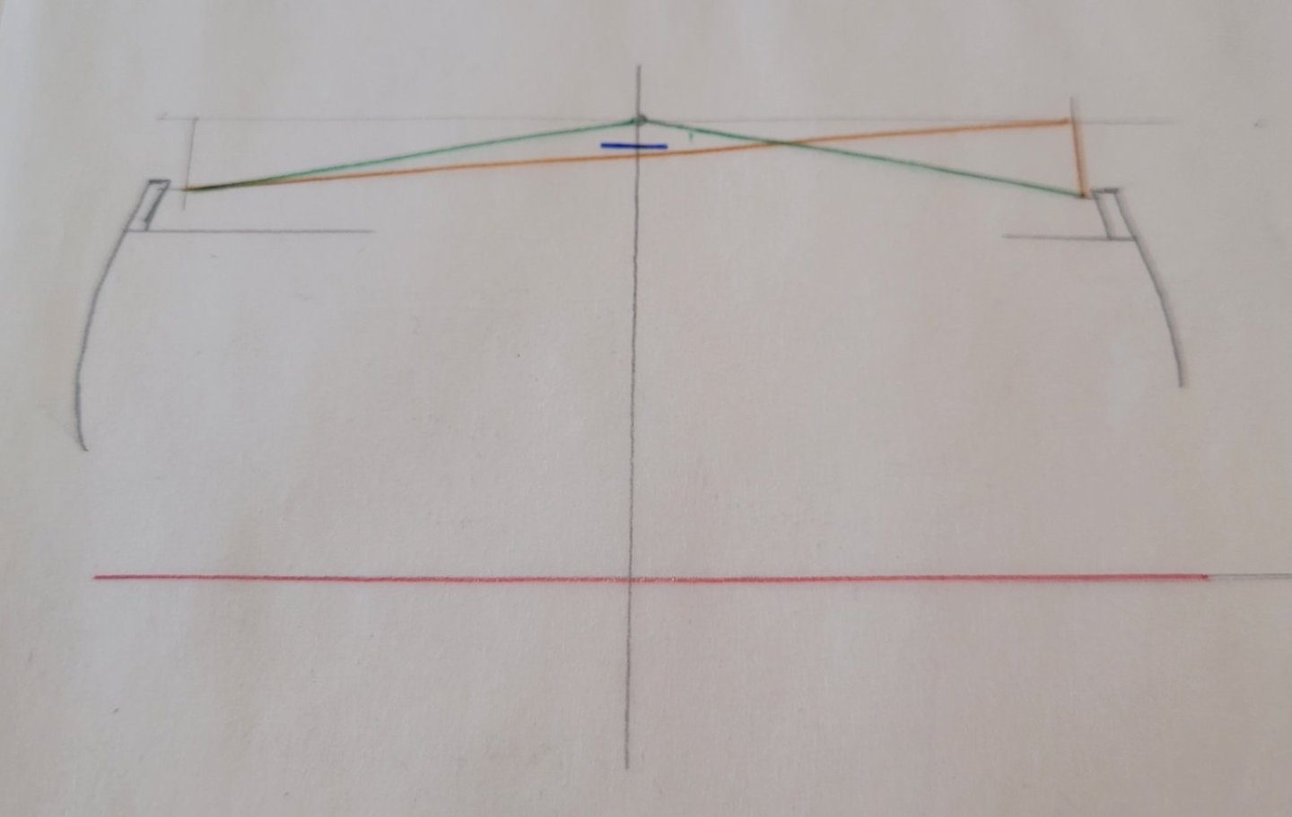
The red line is, as always, the water line. The blue one is the top of the rear cabin and the green and orange triangles show the rough position of the tackle-support in neutral position and extreme deflection.
As you can see, in extreme deflection the tackle cross the level of the roof.
So as I see it, there are three solutions now:
1. Such a large deflection was seen as such a rare case, that it was accepted, that the tackle-ropes rub over the roof
2. The rudder could not that widely deflected, that the tackles could not "cross" the level of the roof.
3. The tackle-support ran in front of the rear cabin.
- mtaylor, Saburo, GrandpaPhil and 1 other
-
 4
4
-
8 hours ago, wefalck said:
As to the tiller, I would assume that it was operated with the aid of tackles, rather than directly by hand.
There are a number of drawings of similar 'postjagden' in the archive of the Danish naval yard in Copenhagen: https://www.sa.dk/ao-soegesider/da/other/index-creator/40/3353816/17149179. They may provide additional useful detail. Check out the drawings with these archive nos.: G-4059 to G-4064.
There are some nice drawings in this archive! Thank you for that 😲 especially the ones showing the rig dimensions will be usefull!
I googled those tackle-supported tillers and I think, this is the way to go. I don't really know, HOW this works in detail, but I will have figured it out by the time, that I build it in scale.
I guess, the helmsman held the lose ends of the ropes of the starboardside and portside respectively in his hands, each one running through a tackle on the ship's side to a tackle mounted on the tiller and back to the outer tackle, where it was fastened.
If this true, the tackle-support ran either right in front of the rear cabin's wall or above its roof. That's another nice riddle. It's almost 10 p.m., so its solution is a task for tomorrow.
-
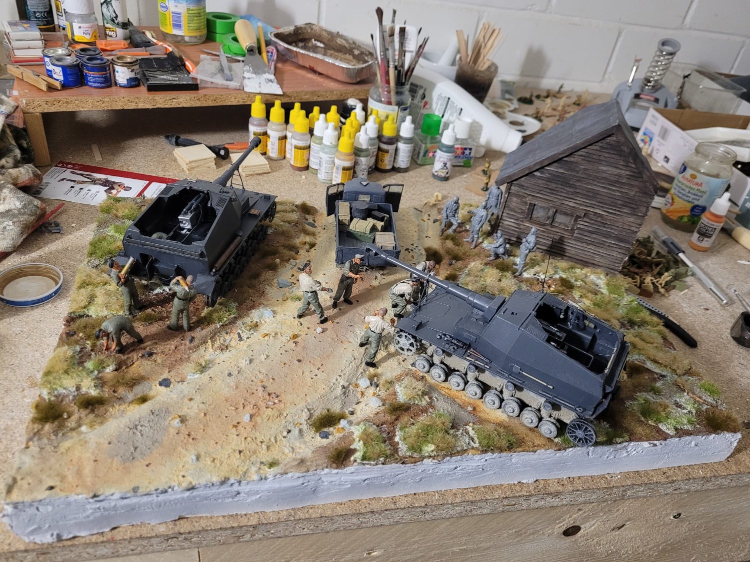
The self-propelled guns are two "Dicker Max"-vehicles. They were bunker busters prototypes built between 1939 an 1941. They are armed with 10,5cm K18 artillery pieces.
The diorama shows them being readied just before the German invasion of the Soviet Union. One of the vehicles will be destroyed five days later by a sudden explosion of its ammunition, the other one will disappear in November 1942 somewhere near Stalingrad.
-
I'm back from my holidays on the german coast of the baltic sea!
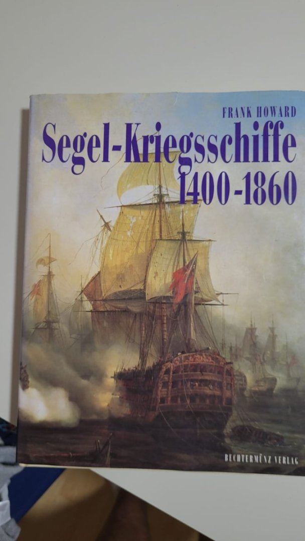
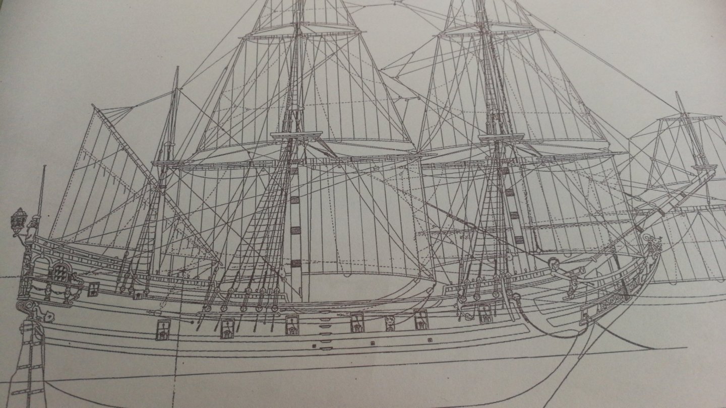
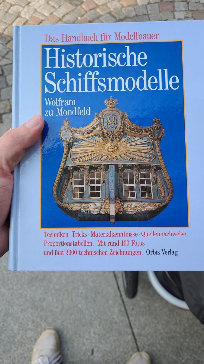
And I brought back another nugget from a flea market 😲 the german edition of Frank Howard's "Sailing Ships of War 1400 - 1860" for a mere 10€ ($10, 8,49 pound). I had walked past this booth at least two or three times and never had never seen it. But as I was about to leave the market, the artwork caught my eye 😆
It might not be directly helpfull with the packet sloop, but you never know, what the future brings.
I also brought home some wood I found in the forest or beach... some birch, beech, something what may be young cherry and a bit of pine. I plan to let it dry, cut it into usefull bits and make parts of the rigging or other details out of it.
-
Hi guys,
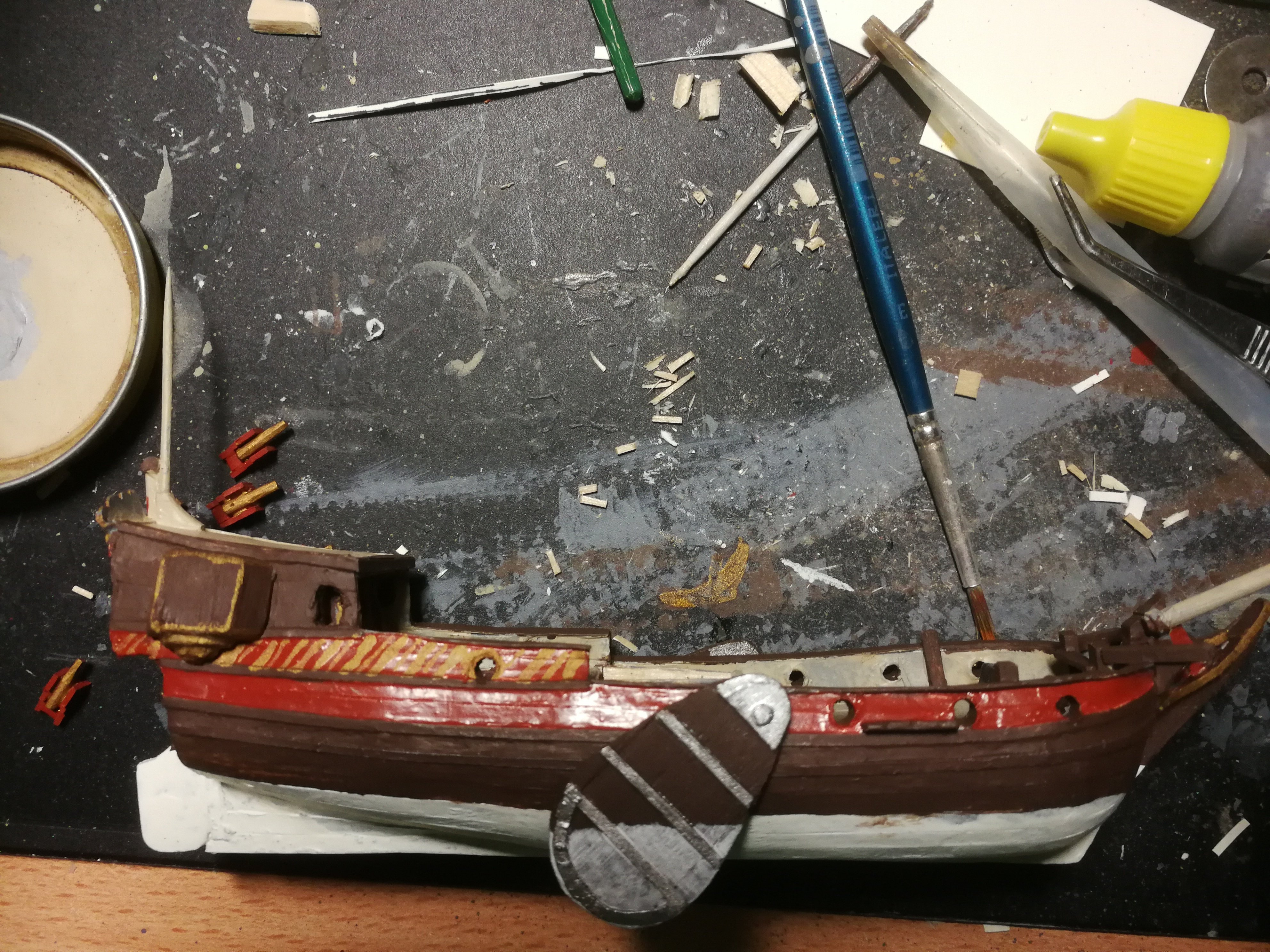
as promised: here come more details and my current progress.
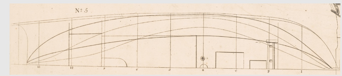
As I've said, I found the plans for the sloop on the internet. Via screenshot and Paint I secured the topview, sideview and "ribview" (pease give me the correct english words, if you may) in a seperate file and pronted the ribview to measure the dimensions and rescale the three plans to 1/35th scale. As noone would have guessed, this went wrong xD the topview came out in 1/35th, the ribview in 1/35,6 and the sideview in 1/47,9. So I measured them all again and re-drew them in said CAD programme. There I "built" it in 1/1 scale and let the PC do the magic to rescale them to 1/35th scale. Why easy, when you can make it difficult.
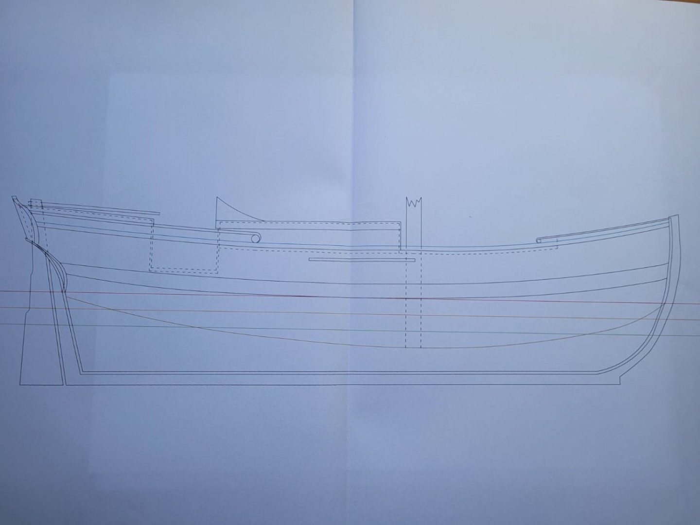
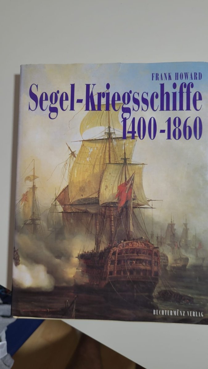
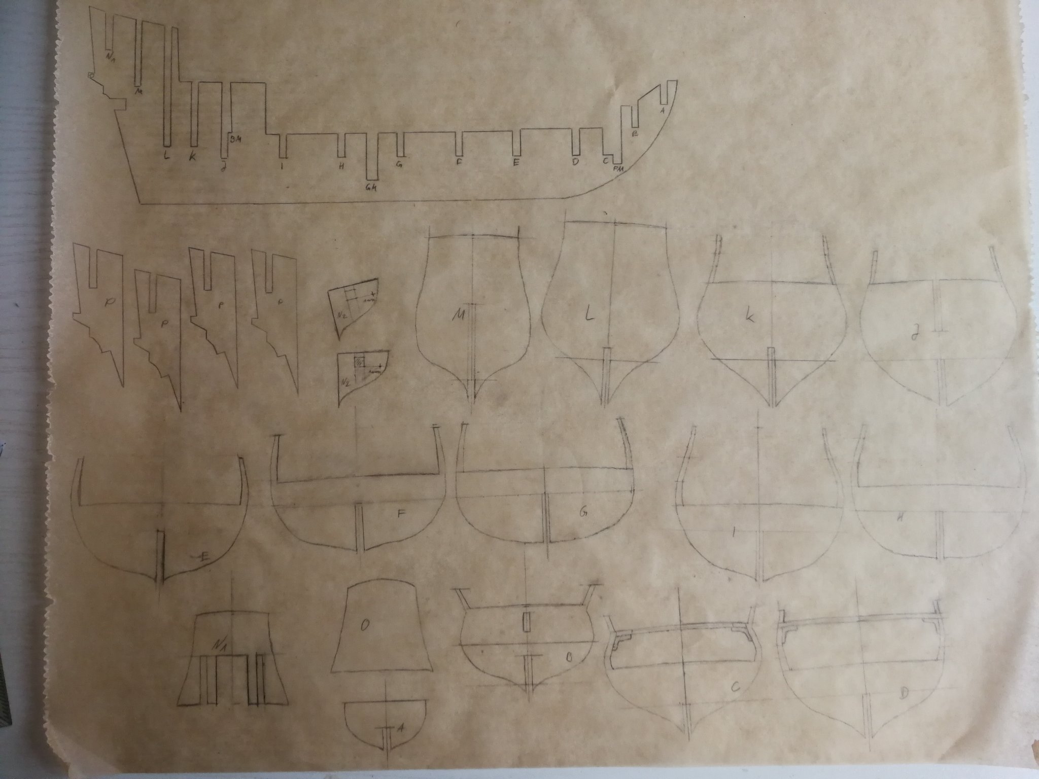
This is the sideview. Don't be confused, the stempost was too complex for the programme (or me) and will be taken directly from the original plans. the dotted lines show the height of the deck and cabins, the same hight minus the thickness of the planking (I took 6cm for deck planking and 3cm for the cabins, which scales to around 1,7mm for the decks and 0,9mm for the cabins)
You will notice the coloured lines. These are also marked in the two other plans and will help me to draw all needed bulkheads.
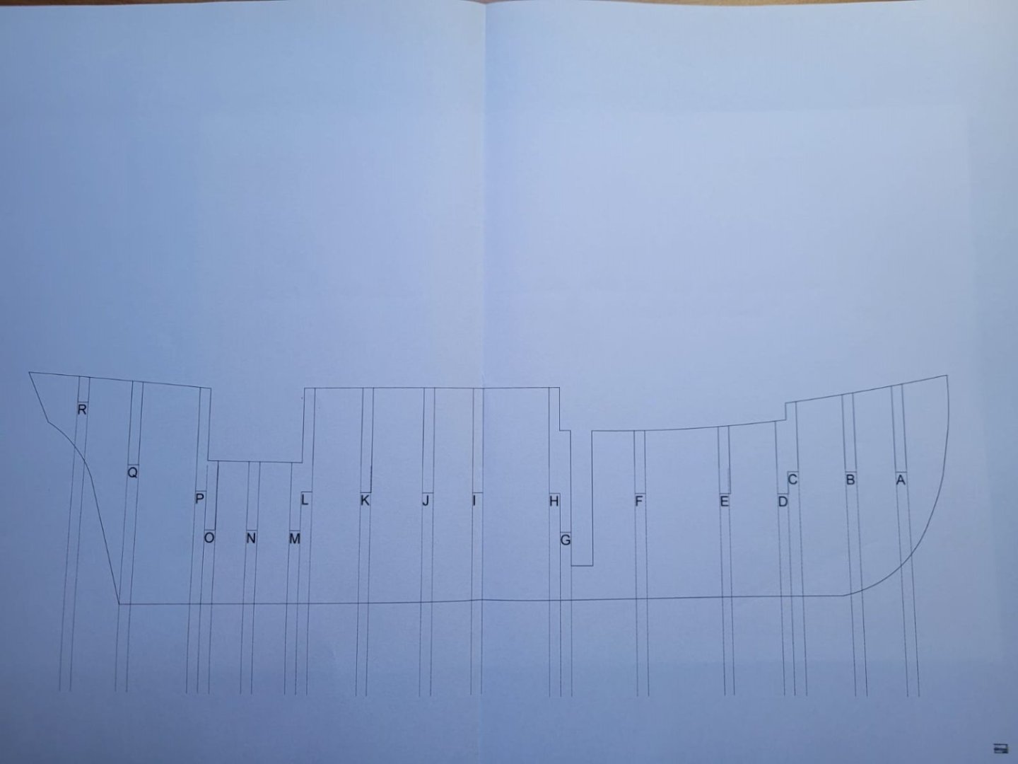
This is the plan for the backbone. It will be made out of 4mm thick plywood. All needed bulkheads are marked. The dotted lines extend to the topview to draw the tapering on each bulkhead.
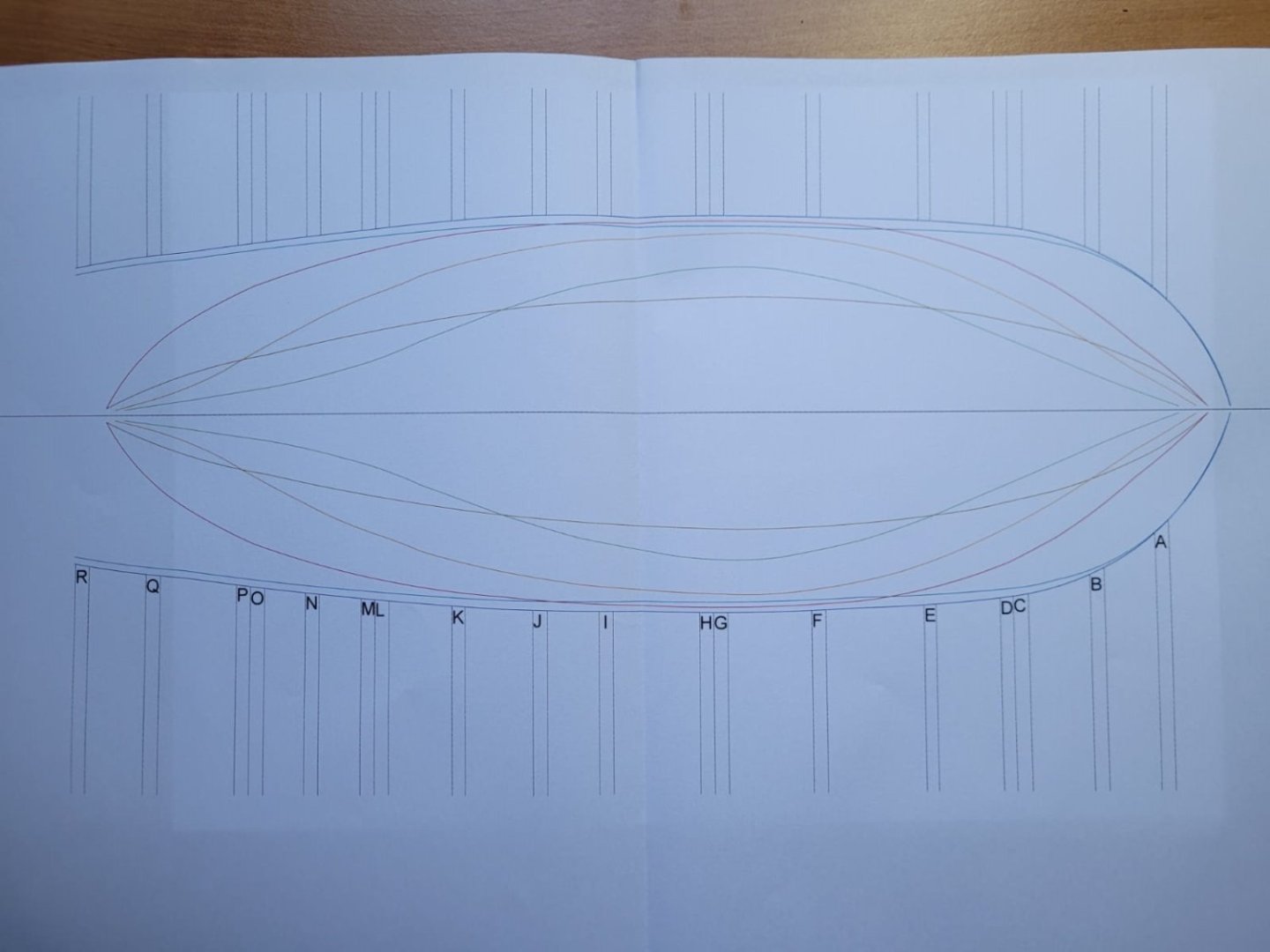
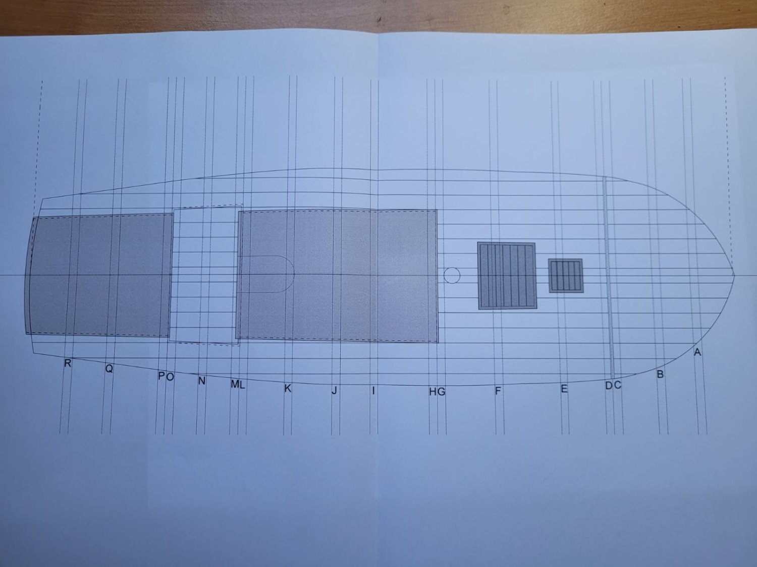
This is the topview, again with all the coloured lines. At the points, where each dotted line coming from the bulkheads cross a coloured line, a line will orthogonally run to the ribview, where it will cross this same coloured line again. This will form the outline of each bulkhead.
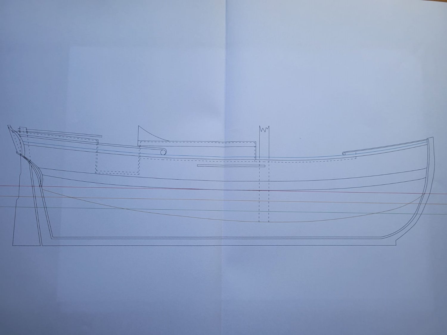
This is said ribview template.

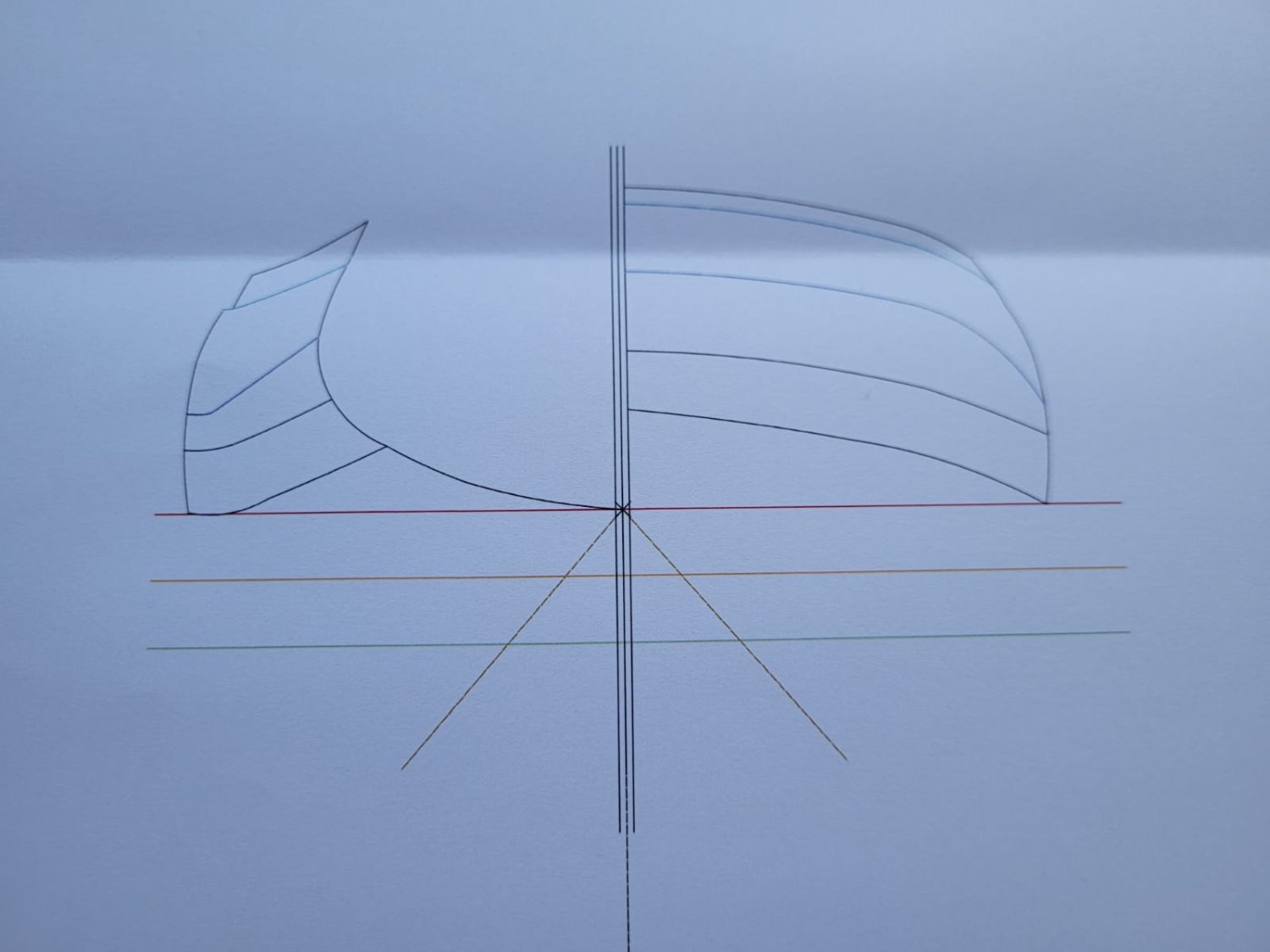
This is the template for the deck and cabins, already with a sketch for the planking. If you compare it to the original topview plan, you will see, that I took artistic license with the rear cabin.
From the original plans it is not clear, where the sides of the rear cabin are. Are they formed by the outlines of the ship (so does the cabine use the complete breadth of the ship) or any other construction? Is the roof flat or more a dome? Like are the side edges of the roof at deck level? There is not even an information about how it was entered (compared to the midship cabin, where there is this semicircular gangway-type of thing).
Wikipedia sais, that those packet ships could be used for passenger transportation too. So my guess is, that the rear cabin was used by the crew (as it is smaller) and the cabin amidships was used for passengers. Maybe it had some windows, a couple of simple beds and something like that.
Another question concerning the rear part is that of the tiller handle. In the sideview, you can see, that it runs hardly above the rear cabins roof (maybe around 5 - 10 cm above it) and merely protruding beyond its front edge. I think, this way the tiller would be hard to handle. Maybe someone can point me towards a possible solution. At the moment, I think about extending it a bit, so that the helmsman could stand before the cabine and handle the tiller.
The last thing I've already drawn are the top edges of bulkhead H to L, which form the walls and roof curvature of the midship cabin.
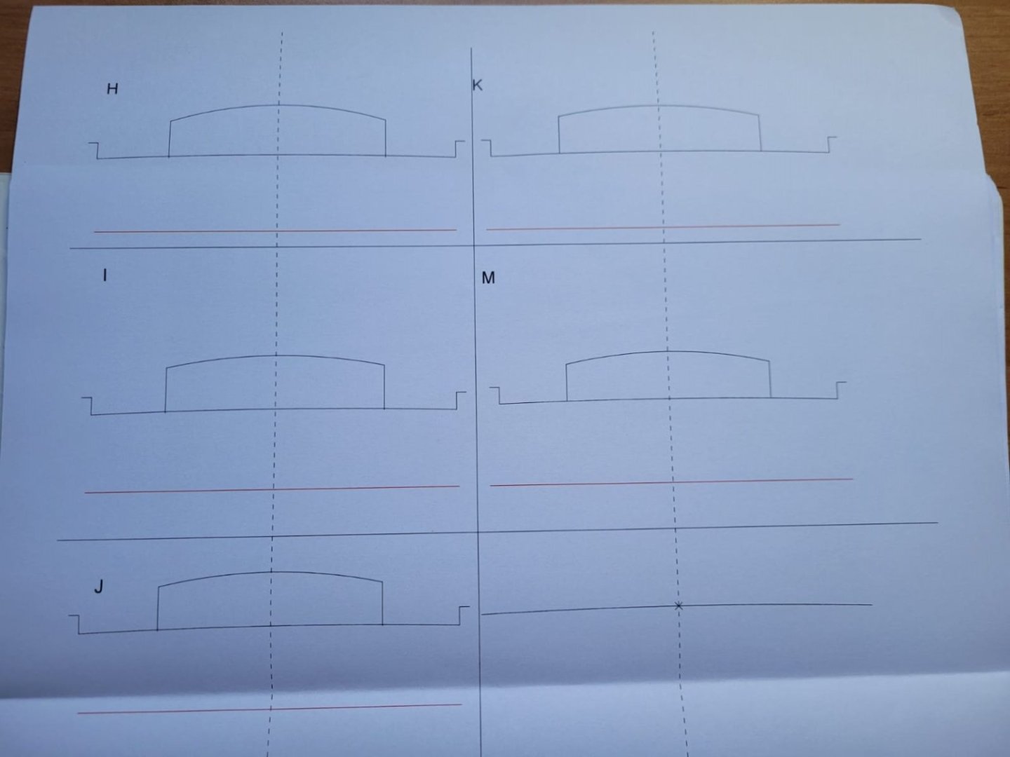
The red line is the water line. My plan is to draw the outlines of the bulkheads in the above mentioned manner on semi-transparent paper and lay this sketch then on top of these templates. In the bottom right is the template for the deck's curvature. The X marks the highest point of the deck, which will be taken from the sideview plan.
Yesterday, I tried to calculate the proportions of the mast and yards according to the charts Wolfram zu Mondfeld provides in his book. There are some big question marks concerning my results, but I will post them later.
Stay tuned!
- uss frolick, bruce d, Saburo and 5 others
-
8
-
Hi guys,
after a long time I'm almost done with my current project. I know, it's not maritime themed, but I'll show it anyways. The tanks only need their tracks and the soldiers in the back some paint. The next project will be a ship again.

I've been uncertain, WHICH ship I should build as a next. There are just too many good-looking vessels out there. My first plans were the Pinas-ship Berlin or the Brigantine Groß-Friedrichsburg, then I favoured more "modern" designs like the french L'Amaranthe (ship-rigged) or the british HMS Speedwell of 1752. Then I found out about the french Etna-Class heavy corvettes, armed with 20 24-pdr guns(!), but I thought "Yeah, all good, but also quite complicated". By chance, I found, that the af Chapman-plans are available online via the archive of the swedish naval museum. I looked them through and there was one boat, that caught my eye.
It's a 38.3 ft long packet boat (Plan XLII, No. 5).
It's small enough to not take up a huge amount of space and to be built in 1:35 scale (like all my tanks) to have a good comparison in size. Also it is - in scale - big enough to not be a fiddly affair (like the Golden Yacht, I've built). Furthermore, with one mast, it is simple enough for me. This will be my first POB build.
As there was not much to do at work during the last week, I was able to draw the plans in the CAD-programme, that we use at work to draw wooden houses or roofs 😆 Pictures of that will follow later. I only had time for the announcement now.
Stay tuned!
- Roger Pellett, dvm27, Saburo and 9 others
-
12
-
Looking nice.
Let me ask you something, I've read some time ago and couldn't really believe about the Rattlesnake: It was said, that her decks were so low, that were mounted under the quarterdeck and forecastle could really not be fired, not to mention to be reloaded. That would have been the reason, the British reduced her armament from 20 to 18 4pdr guns "of the shortest construction". Is this true?
-
Hi guys,
just a quick update. A few weeks ago I bought this book at a flea market. I must say, these were well spent 10€

It's published in the 90ies and shows 100 photographs (even the oldest known ship model) and around 3000 technical drawings and tables of different proportions (diameter of masts or the rig).
It's like a well written roadmap to build a ship from wood fromm start to finish. It has drawings of many different parts including variations, that certain parts had according to time period and/or geografical origin.
Included is a questionnaire of 41 questions that the author recommends to take a look at. They ask things like "Do I have enough pictures and other sources?" or "Am I skilled enough to build this ship in a way I will be satisfied with?". One thing, the author emphasizes greatly is "DON'T WORK WITH BAD PLANS!" If you don't have good ones, search for them and if you don't find them, consider building another ship.
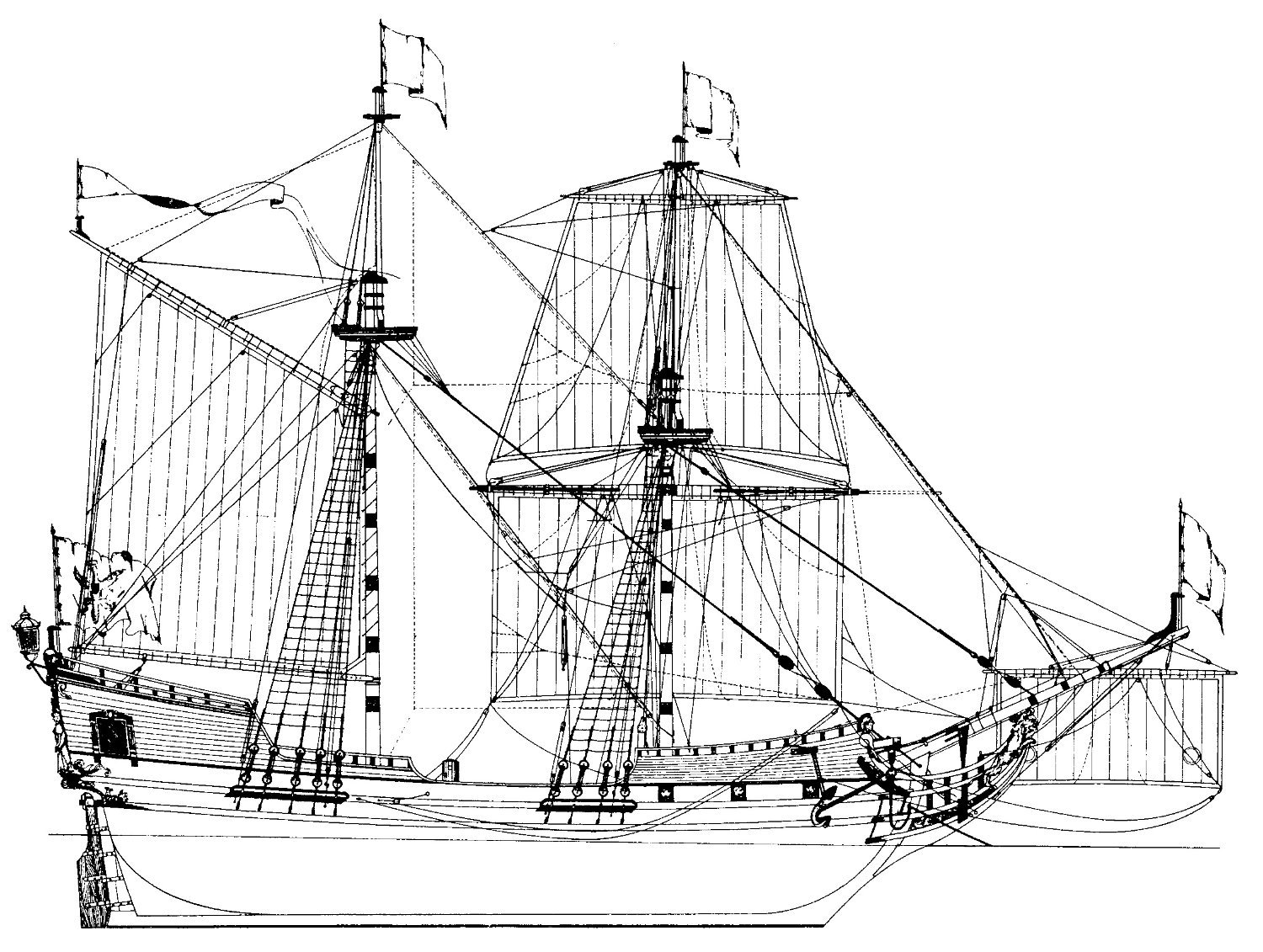
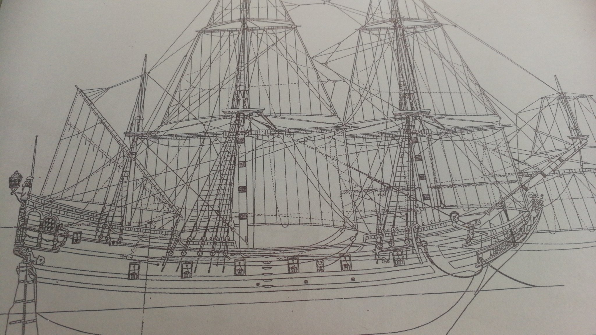
Well, you've seen the quality (or the lack of) of my plans... I think, I will follow his advices and stop the work on the Berlin right now. No cut has been cut, no tear or sweat has run and no bad language has been spoken by now. I think, this project does not fit to my set of skills at this moment. Maybe I will return to it one day, but now, I have laid my eyes on yet another brandenburgian ship: the small brigantine Castell Friedrichsburg
She was a merchant ship of the brandenburgian navy in the late 17th century and took part in the triangle trade, including deporting african people to the american colonies. She was built in 1688 and lost in 1693 on her way from Africa to her home port Emden.
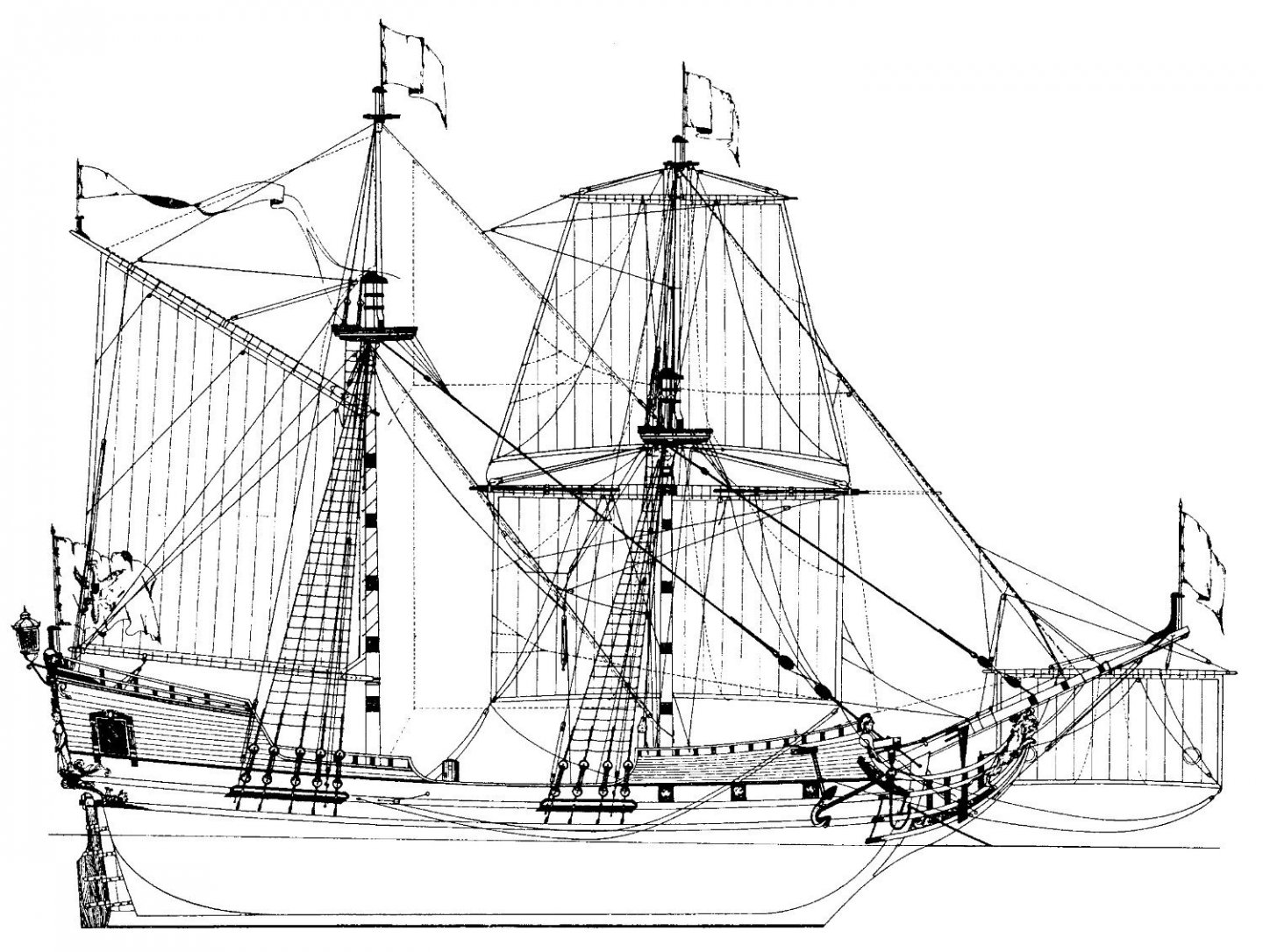
NOTE: my actual plans are of way better quality than this picture
I take her as a base and will alter her design a fair bit.
1. I will include the staysails, jib and top gaff sail, that are just hinted at in this drawing - she looks way better with all her skirts
2. I will increase the number of guns from six to fourteen, maybe sixteen - she looks unbalanced with her few guns concentrated at the bow
3. She will not sail under brandenburgian colours. Maybe pirate, mabye saxony... not yet decided
I'm not yet decided on the scale. My plans are in 1/37,5th scale, but I think, I will scale them down to 1/50 or 1/72 (for the latter one it's easier to find pirate miniatures for height comparison)
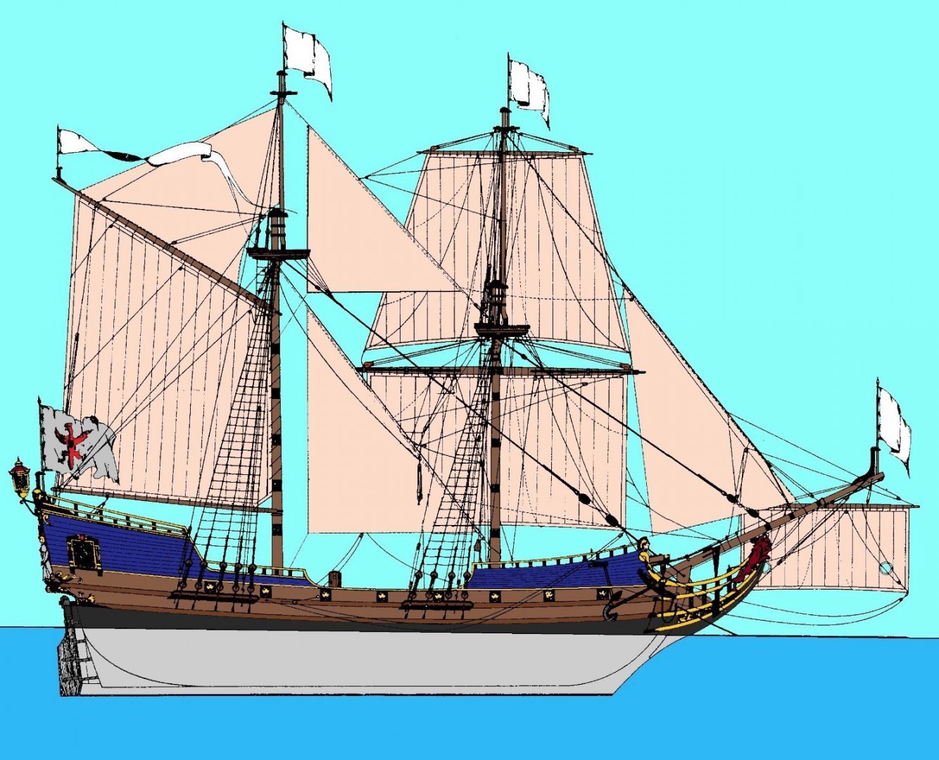
This is an idea of, how she will look like. I'm not sure about the colour scheme. I have two other options in mind: The upper part in copper oxide green (which is blue in this picture), the lower part still bare wood and no black band above the water line OR bright light blue on the upper part, the lower part yellow and black wales as a contrast - a bit like the 1747 HMS Tiger, that is being built by Siggi.
I will use this thread for further updates.
- GrandpaPhil, mtaylor and Archi
-
3
-
Oh Tobias, I hate you so much 🤪
I love the lines of La Palme's big sister - the Frégate de VIII Renommee. I'd love to build her one day, but for now I don't have enough space and some other projects blocking my workbench, that need to be finished.. And now you introduce me to a mini-Renommee! I immediately fell in love and will follow your build log with great interest and - in parallel - look for plans.
The French might have had bad luck with their navy in the 18th century, but their ships looked damn fine!
-
As you've almost directly adressed me and my Yacht d'Oro, I will say some things:
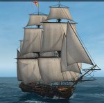
When I built my Yacht, it was my first ship in decades and furthermore the first scratch built one for me. I had pretty bad plans to begin with and I did not question them. I built the bowsprit as the plans called for and what can be seen on this picture, that you posted.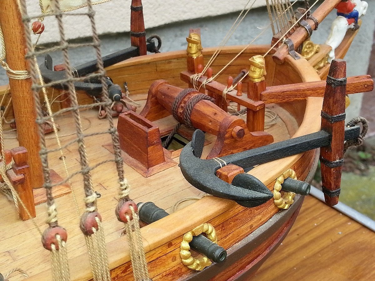
This is one of the things, I would maybe do differently, if i built the Yacht again or at least think about it a bit.
If you ask, how the bowsprit was fixed to the hull, I think you should think about the forces, the pull the bowsprit. In this case, it's the outer jib pulling the tip of the bowsprit upwards. If you fix it to the stem (?) (the place of the forward iron strap on the picture), you create an axis, through which the upward pull of the jib creates a downward push at the butt of the bowsprit. On your picture, the butt is resting upon the reling, which can take these forces. It's furthermore fixated there by another iron strip. So it seems plausible to me, that this version could work. Another versions could be, that the butt rests upon the pinrail (not my favourite option) or another structure or is extended to rest on the deck.
- GrandpaPhil, Keith Black and mtaylor
-
3
-
Thank you all for your quick and very informative responses.
It seems to me, that I underestimated the complexity of aero-hydrodynamics a tiny bit 😅
I thought, there is some kind of a diagram or list that says "windspeed of x km/h produces a pressure of y N/m^2 on the sail" so I can make a rough estimate about how big a force is acting on the point of the yard, which is diverted by the mast itself and the standing rig into the hull. Mast and rig take the pressure relative to their tolerances.
At my current level of skills, I just want to look at the parts of the ship as separate pieces and only in calm sea without waves and a steady amount of wind.
Your book recommendation looked promising, but it is outside my financial possibilities, unfortunately.
-
Hey guys,
In octobre I've started studying civil engineering and looking at a ship, I thought "Isn't a ship just a house with long sticks on top that has to withstand the forces of Walter and move?"
I asked a teacher, who tries to teach is the basics of structural engineering. He turned out to be interested in ships, too, and showed me some basic stuff I can already calculate concerning a boat/ship an calm sea.
One thing that he did not know, was how to calculate the wind pressure. With this I mean the force the wind of a certain speed puts on a piece of cloth (a sail) of a certain dimension.
Is there a book/ebook/epaper, that revolves around this and/or related topics? Questions like "what high a force can a rope of a certain dimension withstand before it starte to fail?" or "How big is the braking force a sail provides?" are also left to be answered.
-
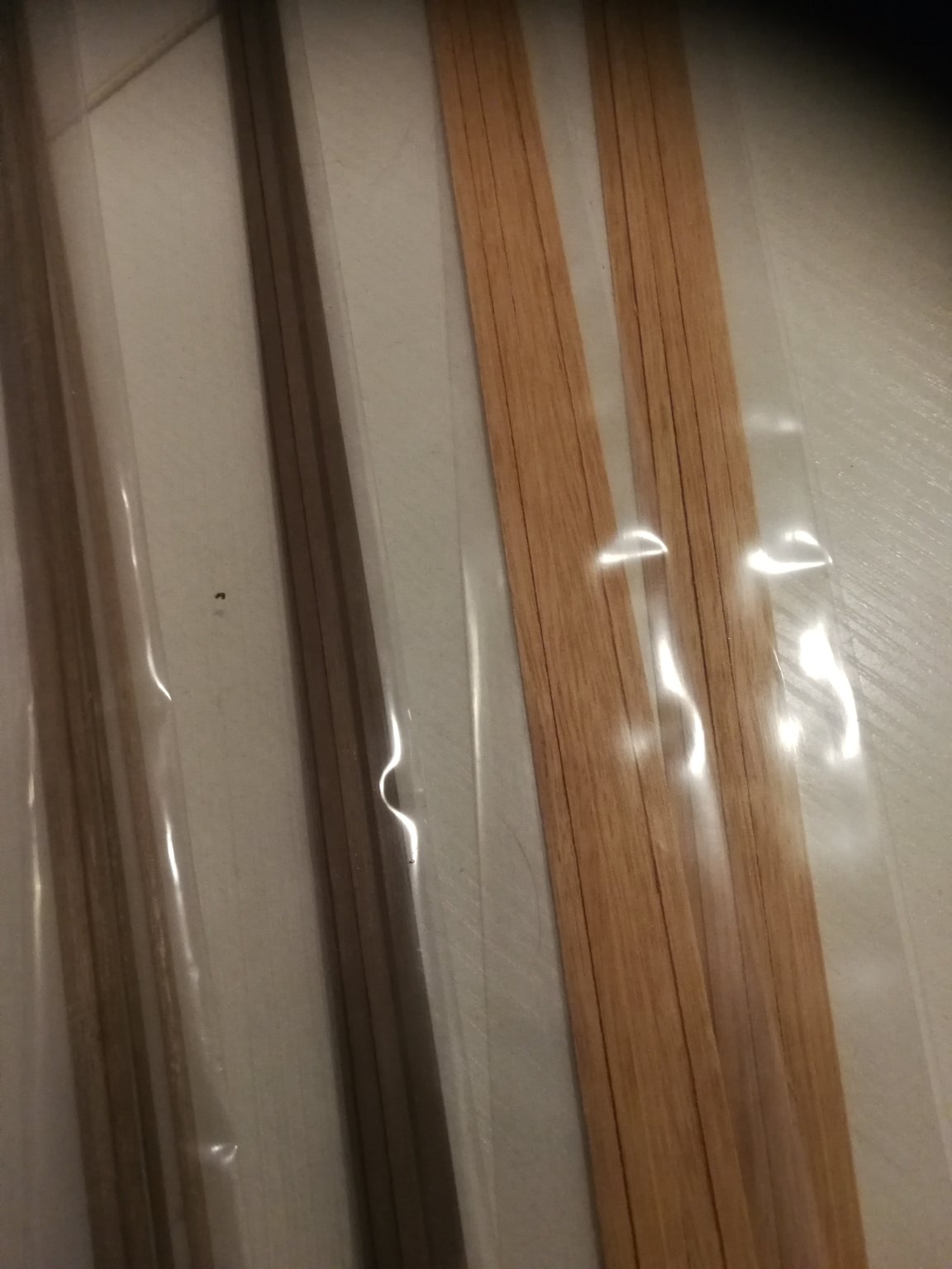
The wood has arrived and I want to show it to you - kind of like a teaser and a sign, that this log is not dead 😅

To the right is Tanganjika-wood for the deck planking. In the middle is nut wood for the hull planking and details and to the left is also nut wood for the mast.
I fear the hull to be a bit dark, but I really like the orange tint of the Tanganjika-wood and the contrast it forms with the nut wood.
Unfortunately, work keeps my busy, so I don't expect to start the Berlin in the near future ☹️
- Archi, Ondras71 and GrandpaPhil
-
3
-
On 2/12/2021 at 5:24 PM, Ab Hoving said:
If I under stand this study correctly, my plans of the Berlin, that seem to be a direct copy out of the sample, you researched here, are in the best case an educated guess, but complete fakes in the worst case.
Well... The historian in my head says "dump the project, as it is not correct", the shipbuilder says "use it as practice.. Noone will notice or care" 🤔
Maybe I build this ship, which claims to be the Berlin, but isn't and build her as any ship I want her to be. Be it a pirate ship or the fictional flagship of the even more fictional saxonian navy 😅
An way, the wood has arrived. I need only some spare time to finish my current projects (three tanks, ten miniatures and a plane 😅) and after that, I can start building the "Berlin"
-
It's been a while, since I've posted an update. But the next step was quite a mental challenge for me. Not because of its difficulty, but because I was not sure, if the results were to be good enough.
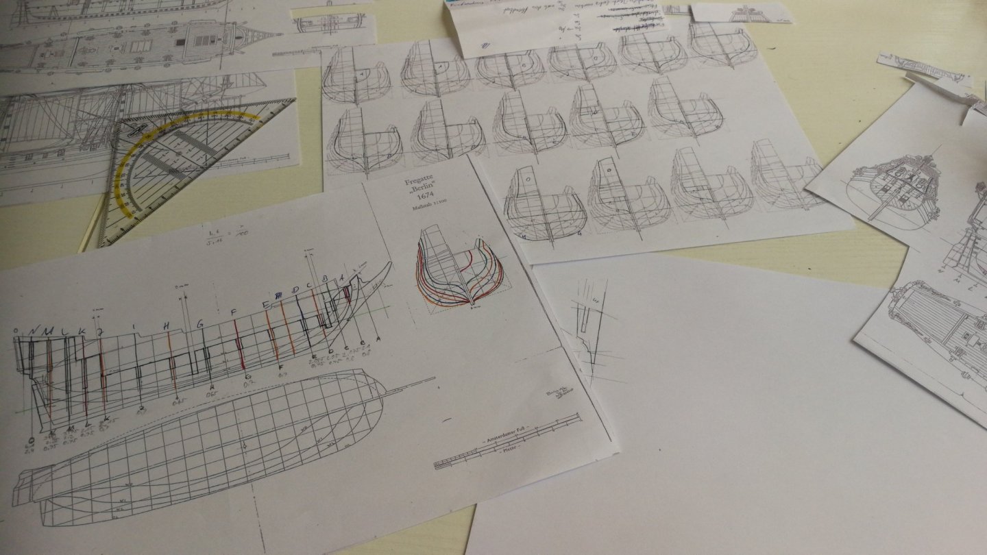
So, here are the finished templates for my Berlin! They were not as tricky as I feared 🤣
The next step is waiting for the wood to arrived.
The bulkheads will be made from plywood. Planks of the hull, masts and yards are from walnut and the decks will be planked with Tanganjica wood. I didn't choose them for any specific reason other than that the decks should be of lighter colour than the hull and rig. Although the Tanganjica could be a bit darker than I think 🤔
Edit: after looking at it a few times more, I came to the conclusion, that I need to reinforce the backbone-section, where frame C and the Fore mast are located. As it is, it may break easily.
- Archi, GrandpaPhil and mtaylor
-
3
-
-
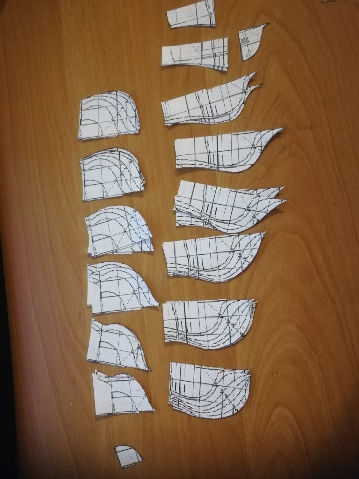
Hi guys,
just a quick update: the templates for the bulkheads are cut out and glued on to backing paper. This way, I have an almost clean base (now on the backside), were I can draw the lines for the decks and outer walls AND see the lines from the templates at the same time.
.thumb.jpeg.6a73eb3837784ca3e9d8c4c6eb763d86.jpeg)
When the time (and wood) has come to proceed with the bulkheads, I will seperate both layers (AFTER drawing all lines 😁) and glue the backing paper to the plywood. At least, that's my plan... If it works, only my future self can tell.

- Archi, mtaylor and GrandpaPhil
-
3
-
Hi guys,
as promised, albeit a little late, here are a few of my reworked plans.
Please forgive the neck gymnastics, that are required to look at the pictures... I turned them the right way, but they were inserted "unturned"
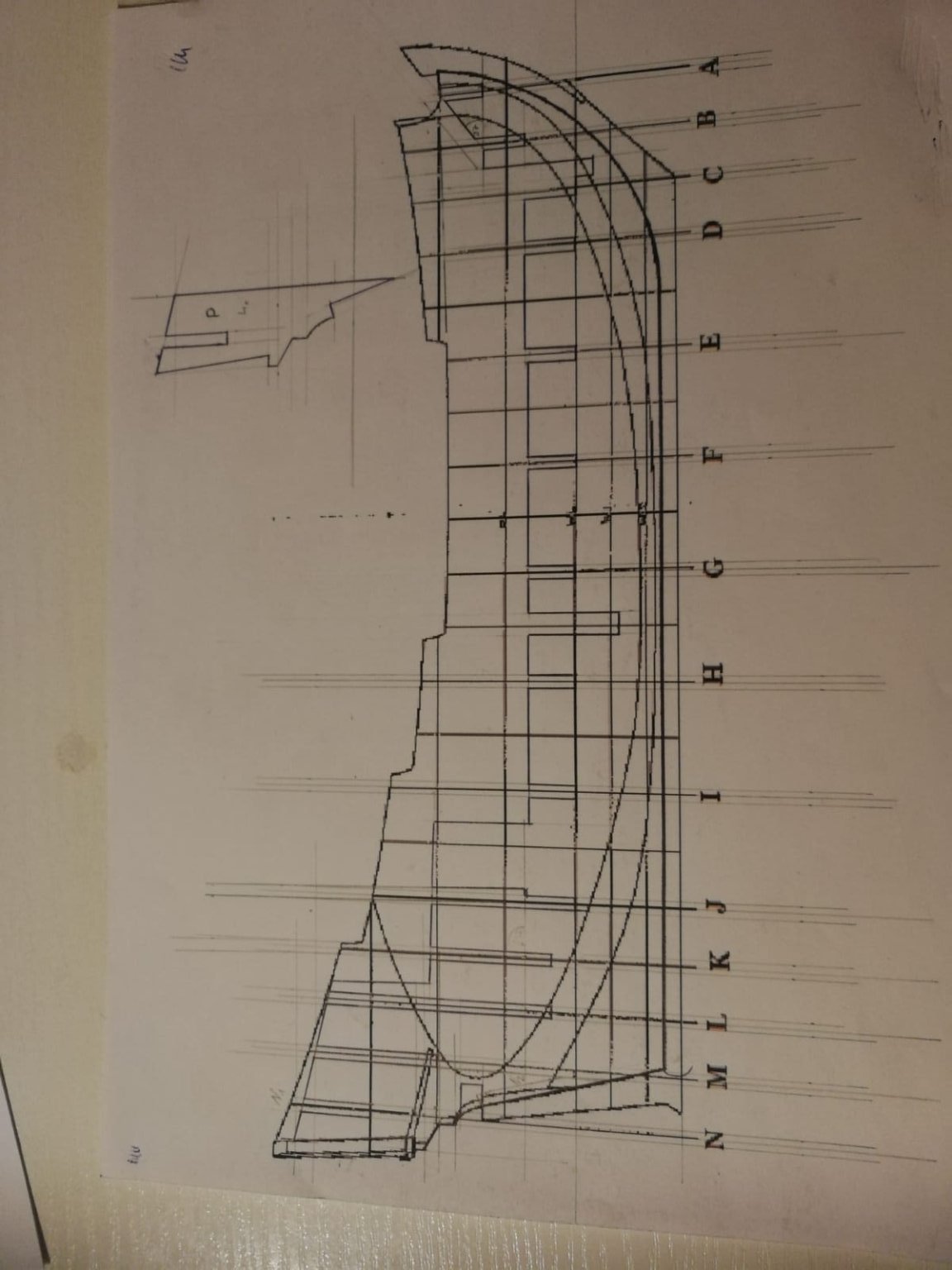
The first shows the backbone.
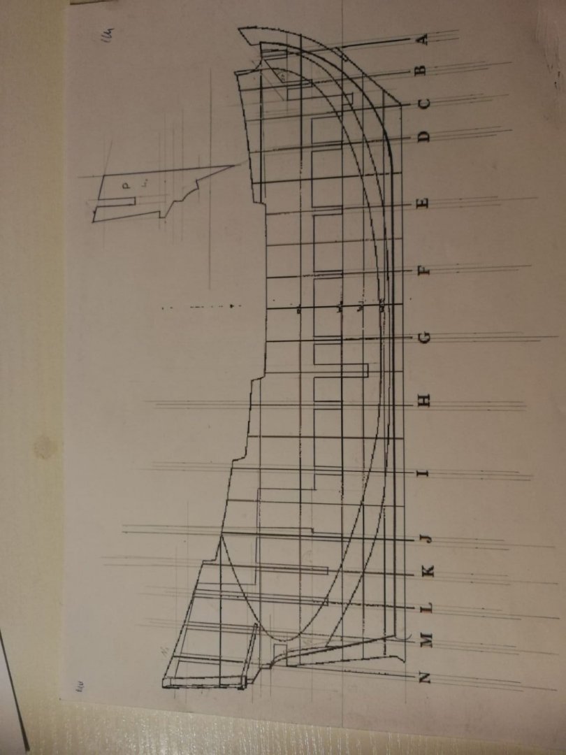
I had a longitudinal section of the Berlin, from which I took the height and placement for the decks and masts. The cut-out at the rear (half way between frame N and the keel) is reserved for the beam connecting the rudder to the inside stuff (terminus technicus unknown 🤔)
In the top left corner is Frame P, which I drew myself. This will be put alongside the backbone to stabilize the rear and give the windows/gun ports below the galery their left and right edge. The cut-outs (steps) on the top and bottem left (rear) side of P are the places for bulkhead N2 (lower) and O (upper), which will form the transom (It's Heckspiegel in german)
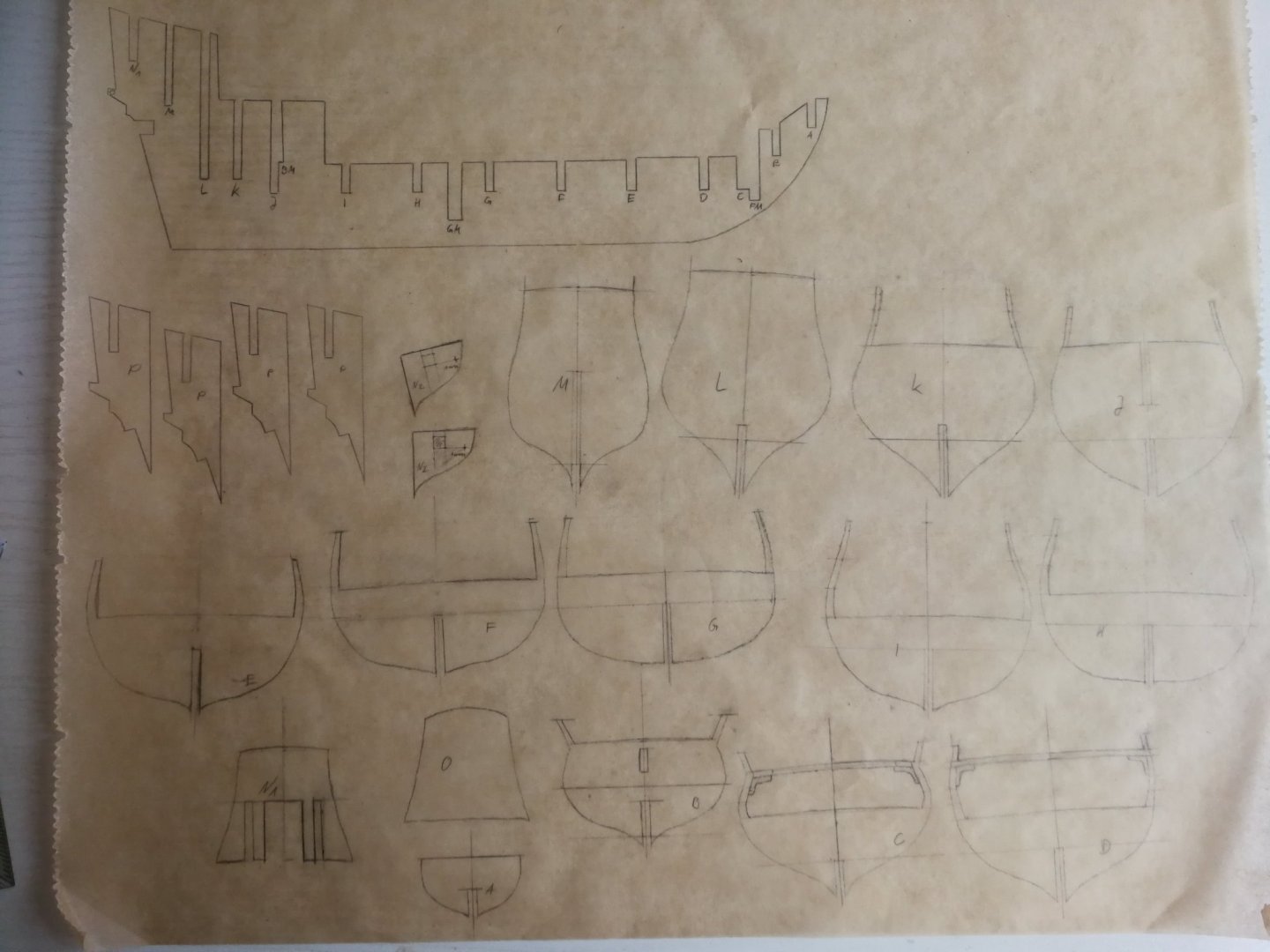
This is one example (of three sheets) for the frames:
.thumb.jpeg.cf1e676e9d1dc5956061ff08aa89066e.jpeg)
I just copied the sketch of the ship's lines 18 times, so that the halves of two sketches form one bulkhead (like there are 2x N1 or N2). I will cut them out and glue them together - either to another piece of paper or to the plywood, that will become the bulkhead. On the top left and lower right sketch, you can see the will-be windows/gun-ports (blue squares)
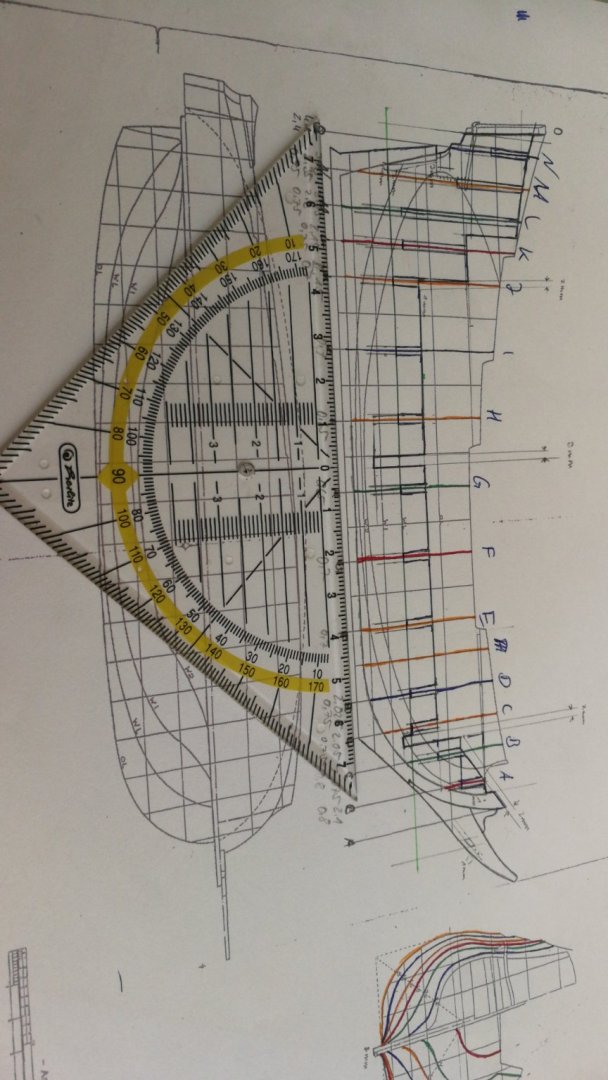
.thumb.jpeg.6767a9b7ba1acee7e68f1716f91b4936.jpeg)
Here you can see a cross section at the place of bulkhead H or I. The measurements at the top (right) are the thickness of the ship's side walls at the different height levels above the water line and the scribbling in the middle is the height difference between the middle part and the edges due to the curvature of the deck.
And last, but not least: the keel parts
.thumb.jpeg.c2893aaff6bee0b18962258d530b5ef3.jpeg)
I took all the measurements of length and angle, but will (most certainly) just cut it out and use it as a template 😆
I am pretty pleased with the results, remembering the low resolution the plans are/were in.
- RdK, GrandpaPhil, mtaylor and 1 other
-
4
-
13 hours ago, RdK said:
Hi,
Very interesting preparation and research. Since it was a dutch-built ship, did you consider to check the beam width to keel ratios of dutch vessels of that time and compare them to the different plans you have?
I would be glad to see you building that model from card and paper! Scale 1:100 is surely not easy from wood. I have never really build a ship from wood except my Elbing Cog (balsa wood, if that counts) but I can imagine that the wood starts to splice easily when making parts that small and tiny?
Looking forward to seeing your progress!
Rgds,
Radek
Hi Radek,
Thank you for your advice concerning the ratios.
I finished the rework of the plans yesterday. The upscaling was not as difficult as I had imagined after I discovered,that this could even be done with Paint
 the results were a bit blurry, but I think I was successfull. (pictures will follow)
I lean more towards working with wood or making a hybrid. The backbone and bulkheads will definitely be made from wood (3mm plywood) due to increased stability compared to card. The planking of hull and decks are yet to be decided. Maybe I'll try wood and if it does not work, I'll switch to 0,5mm cardboard.
I've built the Große Jacht (log is titled Golden Yacht) more or less purely with cardboard and some things worked fine, but others were just a paint. But that's true for the wooden parts, too. I've yet to find my perfect way in 1/100th scale.
13 hours ago, Ab Hoving said:Even the title sounds promising. I'll take a look at it!
Thank you very much.
-
Hi guys,
Browsing through the internet, I found a further four plans of brandenburgian ships. Combined with the Golden Yacht, I could potentially build a whole sixth of the brandenburgian navy, which mustered 34 ships at its peak in 1684. I therefore had the keen idea, to build the five remaining ships and display them all together.
The good thing is: all plans are drawn in 1/100th scale.
The bad thing is: I maybe don't really trust the plans of the Yacht and the Berlin.
If both of them were correct, both ships were of equal size, but the Yacht had one mast and 8 guns, whereas the Berlin had three masts and 16 guns. 🤨 Wikipedia gives both ships comparable lenghts, too (Y: 23m, B: 22,65m). Even the breadth is roughly the same (Y: 6,5m, B: 6,23m).
Furthermore, my Berlin-plans are not matching either! They call the length out to be around 23,5m, breadth 4,6m and height 19,2m (french wikipedia says, the height of the Berlin was 21,5m from head to toe). This means, while the length is almost in scale, the breadth is 27% off and height 11% - IF the measurements on wikipedia are correct in the first place
I am more inclined to trust the measurement of the Yacht, but this means, that the ones for the Berlin are way off.
I then decided to take a look at both Berlin kits. One is by Graupner and made in the 1970's in 1/50th scale, the other one is by Corel, more modern, and in 1/40th scale.
Doing the maths, they come out very similar: length overall between 33,2 and 33,5m (Corel being shorter than Graupner), height between 26,75 and 27,6m (Graupner being smaller than Corel) and a breadth of 7,6m (found only the measurements for the Corel kit)
These sizes sound waay more plausible.
CONCLUSION:
I need to rescale all my drawings *sigh*
Well, trusting wikipedia, at least the plans for the Yacht seem to be correct 😆
I'll be back... soon...
EDIT: I decided to use the Corel kit's measurements as guidelines. New "problem": to match them, I need to lengthen my plans to 139%, raise them to 143,75% and broaden them to 168% compared to their current status. This will be fun 🤪
-
Hi guys,
After finishing my brandenburgian Golden Yacht, I was quite sure, that my next build would be a spanish 22-gun frigate in 1/63rd scale. But as I have neither the tools nor the money for the wood, guns and so on, I kept on looking for my next build. A few days ago, I found the plans for a ship called "Fregatte Berlin" and decided, to give them a try.
Concerning the ship's history:
She was a dutch-built pinnace (and not a frigate^^) and part of the electorial brandenburgian fleet - just like the Yacht.
She was built in 1674 and entered brandenburgian service in the following years. In her first years, she was used for trading with the brandenburgian colonies in west africa and fought the spanish in the war of 1680/81 in the carribean. There she was part of a small fleet of five ships, which managed to capture two spanish galleons.
Her end is unknown, but she remained in brandenburgian service at least until 1684.
I am not quite sure, how I will build her: paper or wood? Only the hull or fully rigged? If wood, then painted or not?
Over the last days, I worked on the plans.
Your comments and advices are deeply welcome!


.jpeg.a2d59a38734aa174f8511bd03eb596de.jpeg)
.jpeg.7fcf18347c0cafe33c2f47dcccdef689.jpeg)
.jpeg.73093433bb3cccf7a40e8eb9cb30de54.jpeg)
.jpeg.49214923eb24684f6b7b4bd3b415828d.jpeg)


Sloop-rigged Pink by Meriadoc Brandybuck - FINISHED - 1:100 - CARD - after af Chapman - first-time scratch build
in - Build logs for subjects built 1751 - 1800
Posted
Hi Meriadoc! Greetings from the 100Rads Bar to the Green Dragon.
I will build a Chapman Sloop myself. ATM I'm working on the plans and trying to figure out several details.
I have the Architectura Navalis myself and in the second half of the book, he writes about different topics, one of which is a chapter about the rigging of ships.
He has one paragraph about sloops, where he said, that the length of the main mast is "thrice" (aka three times) the breadth of the ship. For further details, one shall take a look at the plate in the AN part of the book, that shows all the different kinds of rigging.
As you are a few steps further than me, I will ask you my questions:
1. Do you think the "length of the main mast" means only the lower part (the main mast without top and topgallant mast) or the whole main mast assembly from the deck (or the end of the mast) to the flag?
2. How did you draw the rigging of your sloop? Did you just copy and rescale it or did you use any formula, to calculate the dimensions of each mast and yard? If the latter, what formulae did you use?
BTW you ship looks incredibly good! I personally don't like the lines of a Pink's rear, but you did a great job. Especially as it's your first scratchbuild