


AnobiumPunctatum
-
Posts
1,233 -
Joined
-
Last visited
Reputation Activity
-

 AnobiumPunctatum got a reaction from oakheart in Naval Cutter Alert by AnobiumPuncatum - Scale 1/36 - POF
Thank you, Chuck and all others for the Likes. I hope that I can finish the aft deadwood this weekend.
-
 AnobiumPunctatum got a reaction from KARAVOKIRIS in Naval Cutter Alert by AnobiumPuncatum - Scale 1/36 - POF
The first component for the backbone of the Alert is the Fore Deadwood. This was milled from a piece of boxwood.
Even though I am very happy with the finished part, I will use a different technique for the aft deadwood. Before I could hold the finished part in my hands, I had a few failed attempts. With a much more complicated component, this method is unlikely to work satisfactorily.
-
AnobiumPunctatum reacted to hdrinker in Pegasus by hdrinker - 1:48 - POF - Swan practicum
Breastworks, belfry and waist guns completed.
-
-
 AnobiumPunctatum got a reaction from mtaylor in Naval Cutter Alert by AnobiumPuncatum - Scale 1/36 - POF
Thank you, Chuck and all others for the Likes. I hope that I can finish the aft deadwood this weekend.
-
AnobiumPunctatum reacted to Chuck in Naval Cutter Alert by AnobiumPuncatum - Scale 1/36 - POF
An excellent start...I eagerly await your progress updates.
-
 AnobiumPunctatum got a reaction from druxey in Naval Cutter Alert by AnobiumPuncatum - Scale 1/36 - POF
The first component for the backbone of the Alert is the Fore Deadwood. This was milled from a piece of boxwood.
Even though I am very happy with the finished part, I will use a different technique for the aft deadwood. Before I could hold the finished part in my hands, I had a few failed attempts. With a much more complicated component, this method is unlikely to work satisfactorily.
-
 AnobiumPunctatum got a reaction from GrandpaPhil in Naval Cutter Alert by AnobiumPuncatum - Scale 1/36 - POF
The first component for the backbone of the Alert is the Fore Deadwood. This was milled from a piece of boxwood.
Even though I am very happy with the finished part, I will use a different technique for the aft deadwood. Before I could hold the finished part in my hands, I had a few failed attempts. With a much more complicated component, this method is unlikely to work satisfactorily.
-
 AnobiumPunctatum got a reaction from Marcus.K. in Naval Cutter Alert by AnobiumPuncatum - Scale 1/36 - POF
The first component for the backbone of the Alert is the Fore Deadwood. This was milled from a piece of boxwood.
Even though I am very happy with the finished part, I will use a different technique for the aft deadwood. Before I could hold the finished part in my hands, I had a few failed attempts. With a much more complicated component, this method is unlikely to work satisfactorily.
-
AnobiumPunctatum got a reaction from mtaylor in Naval Cutter Alert by AnobiumPuncatum - Scale 1/36 - POF
The first component for the backbone of the Alert is the Fore Deadwood. This was milled from a piece of boxwood.
Even though I am very happy with the finished part, I will use a different technique for the aft deadwood. Before I could hold the finished part in my hands, I had a few failed attempts. With a much more complicated component, this method is unlikely to work satisfactorily.
-
 AnobiumPunctatum got a reaction from mgatrost in Naval Cutter Alert by AnobiumPuncatum - Scale 1/36 - POF
The first component for the backbone of the Alert is the Fore Deadwood. This was milled from a piece of boxwood.
Even though I am very happy with the finished part, I will use a different technique for the aft deadwood. Before I could hold the finished part in my hands, I had a few failed attempts. With a much more complicated component, this method is unlikely to work satisfactorily.
-
 AnobiumPunctatum got a reaction from Ryland Craze in Naval Cutter Alert by AnobiumPuncatum - Scale 1/36 - POF
The first component for the backbone of the Alert is the Fore Deadwood. This was milled from a piece of boxwood.
Even though I am very happy with the finished part, I will use a different technique for the aft deadwood. Before I could hold the finished part in my hands, I had a few failed attempts. With a much more complicated component, this method is unlikely to work satisfactorily.
-
 AnobiumPunctatum got a reaction from JeffT in Naval Cutter Alert by AnobiumPuncatum - Scale 1/36 - POF
The first component for the backbone of the Alert is the Fore Deadwood. This was milled from a piece of boxwood.
Even though I am very happy with the finished part, I will use a different technique for the aft deadwood. Before I could hold the finished part in my hands, I had a few failed attempts. With a much more complicated component, this method is unlikely to work satisfactorily.
-
 AnobiumPunctatum got a reaction from Niklas in Naval Cutter Alert by AnobiumPuncatum - Scale 1/36 - POF
The first component for the backbone of the Alert is the Fore Deadwood. This was milled from a piece of boxwood.
Even though I am very happy with the finished part, I will use a different technique for the aft deadwood. Before I could hold the finished part in my hands, I had a few failed attempts. With a much more complicated component, this method is unlikely to work satisfactorily.
-
AnobiumPunctatum got a reaction from oakheart in Naval Cutter Alert by AnobiumPuncatum - Scale 1/36 - POF
The first component for the backbone of the Alert is the Fore Deadwood. This was milled from a piece of boxwood.
Even though I am very happy with the finished part, I will use a different technique for the aft deadwood. Before I could hold the finished part in my hands, I had a few failed attempts. With a much more complicated component, this method is unlikely to work satisfactorily.
-
AnobiumPunctatum reacted to Beckmann in TRE KRONER 1742 by Beckmann - 3"/8' scale - Transom-Model
Hello Everybody,
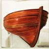
the last weeks I was busy, planking the model. Bending and twisting of planks with dimenson of 2/13 and 2/11 mm was more challenging than I thought ist would be. The curves in the lower areas of the model are very narrow. Here you can see some pictures of the progress.
After this was done, I faired everything.
The colours will be like other contemporary models from the Krigsmuseet in Copenhagen.
Model of CHRSITIAN DEN SIETTE
Model of FYEN
I decided to nail the bright parts of the hull.
After finishing this, I will paint the black areas of the hull an start building the stern and quartergalleries.
I already made the drawings of most of the parts and tested them on the model and prepared the wood to be laser-cut.
It ist all pear-wood I cut in a garden close to the place to our village.
Matthias
-
AnobiumPunctatum reacted to SJSoane in HMS Bellona 1760 by SJSoane - Scale 1:64 - English 74-gun - as designed
HI everyone,
I have not posted in many months, and want to catch up now.
In anticipation of carving the figurehead, I attended the excellent workshop on carving run by David Antscherl and Greg Herbert in Annapolis in early October. Fired up with my newly acquired skills, I flew back home to Montana ready to carve, only to discover that I had pinched the sciatica nerve in my leg on the flight. I was unable to sit at all for several months, taking me entirely out of the workshop. After several months of physical therapy, I am finally able to get into the shop again in small bursts of activity.
During that down time, I put my computer on a stool at my desk so I could work on CAD drawings standing up. I was able to draw many more of the details still to come. I will show some of those in some following posts. Here is a taste:
The unexpected and enforced downtime due to medical issues caused me to realize that I have to get my skates on and work more aggressively towards completion. I may not have the luxury of working for many more years at the same leisurely pace. At the Annapolis workshop, Chuck Passaro discussed with me a number of ideas for tackling the most challenging pieces that were putting me into a tizzy, like the frieze paintings and the fretwork stern decoration, and I am beginning to pursue some of these ideas with him further. Thanks, Chuck, huge help! I am starting with the stern, and here is a sample of what I will discuss in a later posting.
The time off from cutting wood also gave me time to think more carefully about the decorative scheme I will want to follow as I get to this level of detail. I decided at the very beginning that I wanted to show the Bellona as originally designed and built, based on the original Admiralty drawings and on the first Bellona model of 1760 that shows her mainly in frame with little decorative detail other than the taffrail down to the floor of the stern balcony, with no quarter galleries. I did NOT want to portray her as she looked after a major refit 20 years later and shown in the second, fully detailed and colored Bellona model with the coppered bottom. Not only did the latter model show the later structural changes like the changed balcony geometry and the railings along the roundhouse that I do not like, but its overall decorative scheme felt like it was more extravagantly Rococo and showy than the real ship would have looked several decades earlier (like ivory details sprinkled around, and exuberant carvings).
So I have been looking at other models contemporaneous with the first Bellona, like the Princess Royal and the first Victory, both designed by the Bellona's shipwright, Sir Thomas Slade. In some later postings, I will explore this further, as it might be of interest for others who are attempting to reconstruct a decorative scheme from indirect sources.
So anyway, back into the land of the living!
More posts to follow as I am able to put them together.
Best wishes,
Mark
-
AnobiumPunctatum reacted to VTHokiEE in HM Sloop Echo 1781 by VTHokiEE - 1:48 - Cross-Section
I ended up buying the hinge PE set by Mathos Models (I picked up both A and B sets so I can "always be prepared") and I think they worked out well. Unfortunately the bolts became much harder to see after blackening (I assume this is a shadow thing) and I made a CA glue stain (which thankfully is less noticeable no than when I took these pictures). The well and shot locker goes back into storage while I frame out the lower deck.
-
AnobiumPunctatum reacted to Chuck in Sloop Speedwell 1752 by Chuck - Ketch Rigged Sloop - POF - prototype build
Thanks Rusty...
Just a small update...
Now that the aft platforms are completed it made sense to plank the great cabin next. First thing to do was add the laser cut deck clamps. These have notches cut for the qdeck beams. You can see the deck clamp added below. The aft side needs to be beveled to fit flush against the transom. The forward side is left a bit long so you can trim it to fit neatly in place. That forward-most beam notch is a bit longer to give us some wiggle room later for the placement of that beam. In addition before gluing it in...you must shape where the qbadge window is. Sand the shape into the bottom edge of the deck clamp as shown. Because it could be in a slightly different position model-to-model, this detail is not laser cut into the deck clamp.
NOTE the red arrow. The bottom of the notch in the clamp should be even with the top of the window or even slightly higher. But it should not be below the top edge of the windows. If it is, you should make adjustments before gluing it onto the model. In addition, the bottom of these beam notches should NOT be altered. However, when you test fit the beams and find you need to make adjustments, you can absolutely enlarge the notches on the sides and top for a better fit. Just carefully chisel out some of the deck clamp or the planking above it to accommodate your beams.
Next we will plank the inboard side of the great cabin. I am sure most of you could do this without any issues, but to help make it easier, there is a template on the plans. See below.
This should make it easier to cut each strake with the appropriate tapers. There are six strakes. I highly recommend that these planks be cut from a 3/64" sheet as they are somewhat wide at the stern. Plus they are pretty much all drawn out for you. I will also add that you may have to make small adjustments because depending on where you aft platform ended up , you may have a slightly different area of space. Adjust the template accordingly and cut your planks to fit. Again they are 3/64" thick.
Below shows the cabin planked inboard. I carefully cut around that window and did simulate caulking for the plank seams. I just used full length planks rather than show any possible butt joints. They wont be seen anyway. Note the forward edge of the planking runs down the FORWARD edge of the hull frame. Keep the forward esge nice and neat right down the edge of that hull frame.
You might see some laser cut qdeck beams in that picture as well. They are just laying on the lower platform. Although we wont be adding them just yet, it will be to our benefit to have them handy while we do the next steps of fitting out the cabin benches and rudder trunk details. The laser char was removed from the deck beams and they were cut to length. It takes some practice on the first few to get the length correct so they sit nicely in those notches. But dont throw it away if you cut it too short. Just use it for the next shorter beam and work from the forward side aft when doing this.
Test fitting the qdeck beams....none are glued in as I mentioned. Note the extra space on the first beam at the deck clamp notch. This will let us move it around where needed when we start work on the bulkheads there. If any of you are having a problem slipping the beams into those notches, you could easily add another strip of say 1/8 x 1/32 cedar following the bottom of the notches and it would be fine. I did not find the need to do that however. But you might find it easier if there was a second layer that stood proud of the planking a bit to rest your beams on. Builder's choice...
-
AnobiumPunctatum reacted to AON in HMS Bellerophon 1786 by AON – scale 1:64 – 74-gun 3rd Rate Man of War - Arrogant-Class
slow going but I marked all the beams, removed them and am cutting and installing them one at a time to assure all the notches align properly.
slowly getting used to making shallower notches
getting used to it all
by the time I get to the gun deck I'll be... not quite a master at it but much better!
-
AnobiumPunctatum reacted to No Idea in Le Rochefort by No Idea - 1/24th Scale - First POF Build
Ok last one from me! I couldn't resist making the lever for the windlass just to see how it looked. I haven't got a lathe so I winged it a bit but overall I'm happy with the result. I also like the way I can put it in any of the holes on the windlass.
Sorry for the poor picture quality - Mark
-
AnobiumPunctatum reacted to No Idea in Le Rochefort by No Idea - 1/24th Scale - First POF Build
Some more work done on the windlass and this time I've made the Carrick piece (the larger part) and the cheek. But before I made them I wanted to make the big locking bolts that run completely through them. To do this I first had to drill a 0.68mm hole (the smallest end mill that I have) through a 1.5mm diameter brass rod. Here's a close up of the drilling which makes it look like I'm running a 6mm drill through a 10mm bar 😜
A bit of perspective
These were the beginning of the bolts which were then cut to size and a tapered 0.8mm pin put through and soldered in place. I then chemically blacked them and here's the result.
I haven't taken any pictures of the making of the Carrick piece or the cheek as it's very straight forward. I did however take one of the drilling of the holes for the bolts. I temporarily glued the two halves together and ran the drill straight through. This worked great and was very easy to do and once again a little IPA separated the parts.
The finished parts with the bolts in place.
Finally here are parts all dry fitted into the hull. Nothing is glued in at the minute including the beams but it all fits quite nicely.
So thats it for a couple of weeks as I'm in for a quick surgery (nothing major) which they have told me will restrict my lifting and moving. As soon as I'm fit I'll be back on it.
Cheers Mark
-
AnobiumPunctatum reacted to No Idea in Le Rochefort by No Idea - 1/24th Scale - First POF Build
Thank you Vladimir 👍
Hi Dave thanks for your nice comments. I work to the dimensions on Gerards drawings as best I can - so if I measure a piece to be 5.8mm I try and make it that size rather than rounding up to 6mm. I have found that I get very little cumulative error by doing this BTW have a really great holiday you lucky fella 👍
Okay - the windlass 😍 what a lovely piece this is to make on this ship. Although I've not strictly adhered to Gerards drawings as it should be slightly barrel shaped I have enjoyed making this.
So first of all I had a bit of play to work out the indexing on my rotary table which you can see standing on the mill slide. Once sorted I shaped a hexagonal piece which was again made by gluing two bits together. Its dimensions are just over 18mm wide it's quite a chuck of wood.
Looking at the drawings there is a 3 degree angle to be cut on the length of the windlass and also the pawl cut outs are set 12 degrees back from the hexagonal facets.
So I set the 3 degree angle and cut the taper and also rough cut the pawl locations.
Once that was done I revised the pawl cuts and milled them to their final size. This is easy to do as long as you do not accidentally reset your mill dials.
Then I drilled out the holes for the windlass lever which are set a 90 degrees to each other and go all of the way through too. I also cut the windlass bearings.
So now I've ended up with a piece looking like this - Now anyone that does machining knows that my biggest problem is turning the windlass around in the chuck. I cannot grip on the tapered surface with the 4 jaw chuck.
So to solve this problem I made some tapered inserts that I glued on using PVA knowing that I can remove them later using IPA.
I then turned the windlass around in the chuck and repeated the same processes to the other end.
Now the chances of me hitting exactly the same angle with such a Heath Robinson solution was slim. The windlass did not come out entirely symmetrical but it looks ok to me. If I made it again I expect that I would get the same result so upwards and forwards.
The next stage was to make the round holes square for the lever which I intend to make later. I'm sorry but I forgot to take any pictures of this process - Its time consuming to get the square hole completely through but the end result is well worth it.
Finally there are 2 iron bands that fit around each end of the windlass. These are hard to make and get a correct fit being hexagonal - my advice is just keep at it until you get it right. Due to my taper/angle discrepancy the ends of my windlass differ by 1mm so each one had to be custom made.
So here's the final result all cleaned up with blackened iron bands - I've never used brass black before but its very easy to use and the results are lovely.
So next I need to make the windlass supports - Thanks everyone for the likes and support with my build
Mark
-
AnobiumPunctatum reacted to No Idea in Le Rochefort by No Idea - 1/24th Scale - First POF Build
More done this time it's the forecastle deck waterways. As with the main deck these are tricky to make and get a good fit.
Here I'm just pretty much roughing out the shape to get a good fit on the hull and beams. I learn't from last time to leave loads of extra material on until the final shaping.
This is what the final piece looks like - It varies in thickness, angle and profile. I haven't put any of the making pictures up as its a replica of the process that I followed before.
Just dry clamped in place to check that all is ok.
It's all still a bit scruffy and needs cleaning up and pencil marks removed but on the whole they fit nicely and now I know that everything lines up.
So I can now put these parts away until later as I want to make the windlass, stove and office that sit between these decks. Once they are made and installed I'll finally fit all of these pieces too.
Mark
-
AnobiumPunctatum reacted to scrubbyj427 in HMS Portland 1770 by scrubbyj427 - 1:48 - 4th rate 50-gun ship
Allan, for scantlings I found that the deck plans were a great source. The resolution of the scans really allowed me to zoom in quite far in CAD and produce accurate copies. They also worked well in correlation with the inboard profile of Portland. I kept the dimensions of the Timbers very close to the original drawings (keeping modeling and wood production in mind), I ended up with a good representation of what the drawings show.