


AnobiumPunctatum
-
Posts
1,233 -
Joined
-
Last visited
Reputation Activity
-
 AnobiumPunctatum reacted to Chuck in Sloop Speedwell 1752 by Chuck - Ketch Rigged Sloop - POF - prototype build
The next step was to create the bulkhead on the lower platform. This was laser cut. All I had to do was cut some 1/8" x 1/8" strips to simulate the vertical beams. I just cut them to length and glued them on. Now this piece may not actually fit your model perfectly. There are just too many variables. It all depends on where you placed that first platform beam. It also depends on how you faired the interior of the hull. But I sure it could be tweaked in most instances. If you had to, you could use this as a starting point template to make another. It isnt very difficult to do.
This is a picture of the bulkhead glued in position. It is glued on the forward side of that first platform beam. The templates are there to help me during the next step. I will be adding the carlings and ledges. They can be taken right from these templates which are on the plans.
Here is a photo of the ledges and carlings completed. These will support the scuttle lids once planking is finished. I plan on planking the entire platforms. I think it will make creating the various cabins a lot easier.
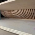
Planking is underway with 5/16" x 3/64" cedar strips. I am not too concerned about getting up close to the sides of the hull. Depending on how fairing went, this could sometimes lead to a weird shape along the edge of the platform. So I concentrated on making a nice shape with the outer edge of the platform deck planking since the sides of the hull inboard will not be planked. I am getting close to the side though and creating a consistent shape port and starboard. It will be impossible to see the sides of this planking when done. Once I get this done I will add the metal work (eyebolts with rings) for those scuttle lids. Then its onto the two aft platforms which are done in a very similar way. Also note the two cut-outs for the legs of the riding bitts. The planks were cut so I could slip the riding bits down into those slots...hopefully!!!
Somebody asked to see a wider shot of the hull with the depth gauge in position. So here is a picture of the hull all dusty after finishing the planking on those forward platforms. Dont hesitate to ask me any questions.
-
 AnobiumPunctatum got a reaction from FrankWouts in Sloop Speedwell 1752 by Chuck - Ketch Rigged Sloop - POF - prototype build
Great idea, Chuck. Thanks for sharing this really simple measuring tool. I love such tools.
-
 AnobiumPunctatum got a reaction from mtaylor in Sloop Speedwell 1752 by Chuck - Ketch Rigged Sloop - POF - prototype build
Great idea, Chuck. Thanks for sharing this really simple measuring tool. I love such tools.
-
 AnobiumPunctatum got a reaction from Nirvana in Sloop Speedwell 1752 by Chuck - Ketch Rigged Sloop - POF - prototype build
Great idea, Chuck. Thanks for sharing this really simple measuring tool. I love such tools.
-
 AnobiumPunctatum got a reaction from Chuck in Sloop Speedwell 1752 by Chuck - Ketch Rigged Sloop - POF - prototype build
Great idea, Chuck. Thanks for sharing this really simple measuring tool. I love such tools.
-
AnobiumPunctatum reacted to Chuck in Sloop Speedwell 1752 by Chuck - Ketch Rigged Sloop - POF - prototype build
Before I can begin placing the beams for the lower platforms, I must make a height gauge first. There are many ways to do this and a system will be very important to have moving forward on this project. Greg describes one method in his books on Speedwell. I have decided to go another way. I prefer to make a depth gauge of sorts.
Here is a photo...you folks can of course select any method you prefer. I am fond of this one and such a gauge can be made with readily available scrap strips...Note how the pointer is a separate it to be slipped onto the lower shaft. It is basically a very large T-square. I used 3/32" thick strips but they are fairly wide so they wont bend or flex. The center of the "T" is thinner at about 1/16" thick.
The pointer is meant to be slid onto the center shaft of the "T". Everything is squared up and at perfect right angles. Nice and neat.
Basically take the measurements from the plans to find the depth of any beams etc. Like the forward platform beams. The underside of the "T" is set flush with the sheer on the plan. Then I mark the top of the platform beam on the center shaft...without the pointer on it. Just a pencil tick mark.
Then the pionter is added to the shaft and lined up with the tick mark. The pointer must fit nice and snug so it doesnt shift around. Its a very tight fit on purpose. Then the depth gauge can be brought to the model as shown. Repeat on both sides for each beam end. I am marking the height for the tops of the beams. Find where that beam should be and mark its height on the model. Repeat this process for every lower platform beam end. Then connect the marks to find the proper height for the platform. Basically repeat this on both sides. Hope that makes sense.
I am basically trusting that my sheer on the model is correct and even on both sides. I am confident...
But if your sheer is off you have bigger problems anyway. No matter what method you choose there will be issues. This is just one method that can be used. I did this for all the lower platform beams which are 3/16" x 3/16" cedar. That is except for the most forward platform which has 1/4" x 3/16 beams just under the stove. Check you plans carefully. The beams have no roundup and are just cut from strip stock. They are carefully measured and shaped to fit snug. Placement is important here.
In fact the placement of the first 1/4" x 3/16 beam of the forward-most platform is very important. It is exactly 5/16" away from the beam aft of it on the lowest platform. So a small jig was laser cut to help find its location. This will be provided. It sits on the lower platform beams which went in first. It has laser etched marks to help you place that first beam in position correctly at the right height and the right distance from the lower platform beam.
Once all seven of the forward platform beams were in place I tested my placement with the a cutout of the plans. Everything is level and the plans fits pretty darned good.
Next up is to add the a bulkhead and some additional framing on these platforms before I plank them.
Hope this makes sense...
Chuck
-
 AnobiumPunctatum got a reaction from JpR62 in Naval Cutter Alert by AnobiumPuncatum - Scale 1/36 - POF
It's time to put the dust away. Ten years ago I started with great enthusiasm the build of the small cutter. But to be honest I was not able to reconstruct the framing of the cutter. So I stopped after some time and paused the project. In October of 2022 I started a new try.
I lerned a lot and made a complete rework of my reconstruction. The first two pictures are showing a 3D-model which I used to check my lines.
As written in the old posts I was not happy with the frame design in Goodwins AotS Book. In my opinion, it does not fit into the time in which the cutter was built. There are several DoF plans of small ships of this era in the NMM. What almost all of them have in common is that the double frames were dissolved. A space was also left between the first futtock and the floortimber. However, the "double frames" were still connected by chocks.
The picture shows my reconstruction. I have it a little bit simplified, because I w like to plank the hull, so the shifted top timbers will not be visible. Many many thanks to @Chuck who gave me the inspiration for the simplification.
Since February last year I am working on the model. All parallel frames have been built in the meantime. I am now busy with a second version of the backbone.
The build is more or less a test to learn working with my CNC. In November I have started working on my sloop Fly again. The plan is to build and test the building methods on Alert and use this than for my ship sloop.
-
AnobiumPunctatum reacted to 72Nova in Sovereign of the Seas by 72Nova - Airfix - PLASTIC
The detailing of the bulkheads is finally complete, obviously a lot of artistic license used here, but looks like a decent representation, now I can get back to work on the hull prior to glueing it up then finally set the decks in place.
Michael D.
-
AnobiumPunctatum got a reaction from FrankWouts in Sloop Speedwell 1752 by Stuntflyer (Mike) - Ketch Rigged Sloop - POF
It's looking really good, Mike
-
 AnobiumPunctatum got a reaction from dafi in Naval Cutter Alert by AnobiumPuncatum - Scale 1/36 - POF
It's time to put the dust away. Ten years ago I started with great enthusiasm the build of the small cutter. But to be honest I was not able to reconstruct the framing of the cutter. So I stopped after some time and paused the project. In October of 2022 I started a new try.
I lerned a lot and made a complete rework of my reconstruction. The first two pictures are showing a 3D-model which I used to check my lines.
As written in the old posts I was not happy with the frame design in Goodwins AotS Book. In my opinion, it does not fit into the time in which the cutter was built. There are several DoF plans of small ships of this era in the NMM. What almost all of them have in common is that the double frames were dissolved. A space was also left between the first futtock and the floortimber. However, the "double frames" were still connected by chocks.
The picture shows my reconstruction. I have it a little bit simplified, because I w like to plank the hull, so the shifted top timbers will not be visible. Many many thanks to @Chuck who gave me the inspiration for the simplification.
Since February last year I am working on the model. All parallel frames have been built in the meantime. I am now busy with a second version of the backbone.
The build is more or less a test to learn working with my CNC. In November I have started working on my sloop Fly again. The plan is to build and test the building methods on Alert and use this than for my ship sloop.
-

 AnobiumPunctatum got a reaction from Mike Y in Naval Cutter Alert by AnobiumPuncatum - Scale 1/36 - POF
It's time to put the dust away. Ten years ago I started with great enthusiasm the build of the small cutter. But to be honest I was not able to reconstruct the framing of the cutter. So I stopped after some time and paused the project. In October of 2022 I started a new try.
I lerned a lot and made a complete rework of my reconstruction. The first two pictures are showing a 3D-model which I used to check my lines.
As written in the old posts I was not happy with the frame design in Goodwins AotS Book. In my opinion, it does not fit into the time in which the cutter was built. There are several DoF plans of small ships of this era in the NMM. What almost all of them have in common is that the double frames were dissolved. A space was also left between the first futtock and the floortimber. However, the "double frames" were still connected by chocks.
The picture shows my reconstruction. I have it a little bit simplified, because I w like to plank the hull, so the shifted top timbers will not be visible. Many many thanks to @Chuck who gave me the inspiration for the simplification.
Since February last year I am working on the model. All parallel frames have been built in the meantime. I am now busy with a second version of the backbone.
The build is more or less a test to learn working with my CNC. In November I have started working on my sloop Fly again. The plan is to build and test the building methods on Alert and use this than for my ship sloop.
-
 AnobiumPunctatum got a reaction from Saburo in Naval Cutter Alert by AnobiumPuncatum - Scale 1/36 - POF
After the drawing works it was time to make sawdust.
First part is the keel, which is a little bit tricky. The keel has a light curvature and the joints are perpendicular to the base line.
I cut some small stripes with my cirular saw, make the joints and glue the parts together. Next I added the parts for the stem.
The picture shows the step on the building board. I use Tamiya Tape to avoid that the keel glues on the paper during the build.
The next pictures show the complete assembled backbone for the small vessel,
the stem with with the changed layout of the parts,
the keel and the rising wood,
and the stern post with the after deadwood.
The next steps are cutting the rabbet, the keelson and the building board. Then I can start with the frames.
-
AnobiumPunctatum got a reaction from Saburo in Naval Cutter Alert by AnobiumPuncatum - Scale 1/36 - POF
I was really suprised that I did not find a build log about the Naval Cutter Alert on MSW 2.0. I know that there exist some pictures of a model on the old MSW
The first source for building a model of this small vessel are Peter Goodwins book "The Naval Cutter Alert, 1777", published by PhoenixPublications Inc. 1991 and the two original drawing of her sister Rattlesnake (1776) which you will find on the homepage of the NMM.
There also exist two paintings of Joseph Marshall of the ship, which are exhibited in the Science Museum, London.
I found also an Sheer and Profile drawing of Alert which was published by the NRG.
The sheer and profile of the NRG and Goodwin differ from the original drawing. They show the maximum width of the ship not at frame 0. Perhaps my Engish is to bad, but I could not find any reason for this. So I decide to draw my own lines. which were based on Goodwin and the original drawing.
The drawing is not finished, because I decided only to draw what I need for my build.
Next step was the keel. Goodwin shows for the pass between keel and lower apron a solution which I could not find on any original cutter drawings.
For the after deadwood he does not offer any possible solution
I decide to follow the original drawing of Cheerful 1806 for the pass between keel and lower apron. The flat joint at the foremost keel part is shown on original drawings of this period (for example on HMS Triton). For the after deadwood I decided to use a bearing line. I am not sure if this is common for ships of this period.
The next picture shows my completed keel drawing:
Goodwin uses for his design the common frameing pattern of double and single frames. I am not sure that this design was used for the original ship. For the Swan class sloops only single frames were used. This you will also find on the drawing of Cheerful and other cutters. Also the wide of the frame parts are not clear. In his drawing he uses much smaller futtocks than he descibed in the text part of the book. In his "Construction and Fitting of Sailing Man of War" he gives a third solution.
What now? Alert is a practice model for me to get the experience to continue my HMS Fly build. Marshall shows on his paintings an simplified frameing design, so I decided to use this. Every frame is 8'' width followed by 8'' space. For the port side I like to show the clinker planking.
On my drawing the final design for the last frame and the hawse pieces is missing in the moment.
The drawings for every 31frames and 21cant frames are finished.
I am not sure in the moment if I will use the original practice with chocks or the simplified method of Harold Hahn for my build.
It will be very nice if you have further information about the cutters of this time. I found the Marmaduke Stalkartt on Google-books, but they didn't scan the plates. Perhaps one of the MSW user can help me to confirm my decisions.
-
 AnobiumPunctatum got a reaction from Tobias in Naval Cutter Alert by AnobiumPuncatum - Scale 1/36 - POF
It's time to put the dust away. Ten years ago I started with great enthusiasm the build of the small cutter. But to be honest I was not able to reconstruct the framing of the cutter. So I stopped after some time and paused the project. In October of 2022 I started a new try.
I lerned a lot and made a complete rework of my reconstruction. The first two pictures are showing a 3D-model which I used to check my lines.
As written in the old posts I was not happy with the frame design in Goodwins AotS Book. In my opinion, it does not fit into the time in which the cutter was built. There are several DoF plans of small ships of this era in the NMM. What almost all of them have in common is that the double frames were dissolved. A space was also left between the first futtock and the floortimber. However, the "double frames" were still connected by chocks.
The picture shows my reconstruction. I have it a little bit simplified, because I w like to plank the hull, so the shifted top timbers will not be visible. Many many thanks to @Chuck who gave me the inspiration for the simplification.
Since February last year I am working on the model. All parallel frames have been built in the meantime. I am now busy with a second version of the backbone.
The build is more or less a test to learn working with my CNC. In November I have started working on my sloop Fly again. The plan is to build and test the building methods on Alert and use this than for my ship sloop.
-
AnobiumPunctatum reacted to scrubbyj427 in HMS Portland 1770 by scrubbyj427 - 1:48 - 4th rate 50-gun ship
So I worked on some support jigs today along with the forward frames. There are three total jigs that are placed on the structure, these will remain there until the planking is completed and all the frames are supported.
This is a large model with lengthy unsupported frames sticking up just asking to break off, I didn’t feel comfortable fairing and planking these without some major support through the process.
The first jig is forward, it will support a larger piece that will lock the frames together and the second is in the middle it will also support this piece, both of these are represented in orange.
Below you can see the forward frames in blue, I’ll cover these first since the forward jig is dependent on these.
The pieces below are for the port side, they have fairing lines etched in already, I just sanded them carefully and test fit until I was happy. The frame you see is the forward bulkhead and timber support, this will go in last.
I had already compleated the starboard ones and installed them with the fwd bulkhead frame, I did a little bit of fairing once installed and I’ll probably have to do a little more when I fair all the bulkheads.
All three jigs are a pretty tight fit but I want them to be sturdy and keep the frames true, so some sanding and filing may be required, the assembly of the first one is shown below
The two pieces above fit snug on the outboard side of the fairing frames on frames 1,2and 3, they are all marked with arrows facing forward so you get the direction right
I should add that the flat piece on the center of each jig is there to attach the bulkhead jig to, I had intended to just screw it down to this piece but may glue it in and just break it out when it’s time to remove. all of this will come out once it serves its purpose.
The middle jig is similar and you can see below, it fits between frames 12 and 13.
Once the jigs are complete, the large piece that stabilizes the bulkheads will go on, it also acts as a parts tree for the gunport frames as well as the gunport cutouts to help you get the frames installed at correct angles.
I will cover this in detail much more later as i still have to build the third jig which also supports the frames, unfortunately I forgot to cut some pieces and bring them back with me.
JJ
-
AnobiumPunctatum reacted to scrubbyj427 in HMS Portland 1770 by scrubbyj427 - 1:48 - 4th rate 50-gun ship
So after a week of waiting on some parts to show up that I had cut wrong prior, I was finally able to get back on track.
I started by assembling the bulkhead former, this is in 3 pieces but I’m toying with switching to two or possibly even one if I can find a box large enough. This goes together pretty easy, I used wax paper and smashed it in a vise until the joint was dry and then repeated until complete. I also added a rabbet strip, this was just basswood I cut on my saw, it required slight heat on the bow to make the curve easier.
Next is the knee, at 1/48 the knee and the false keel parts are just shy of 5/16 which is great, it will leave you some room to sand the parts and that’s what I did, now all these parts are two pieces of 5/32 AYC glued together, cutting 5/16 in one shot just had too much angle to it, it made assembly pretty difficult, but I’m still working on trying to improve the laser cut, perhaps I’ll get it in one piece someday but not for this model.
As you can see i just etched some of the parts on to the main part of the knee, this is actually pretty convincing, I did however toss in a reference line for the paint and where the wales meet the knee, I don’t like it and probably won’t keep it there, but it will get painted over on this model anyway.
Once the knee and all the false keel parts were assembled I measured the width of the former and subtracted it from the cedar pieces, using this number, roughly 1/32, I layed the former down with the 1/32 spaced sheet underneath and glued the knee and keel parts onto the rabbet. This kept everything in line and centered very well. I carefully sanded the AYC with 100, 220 and finally 320 and gave it a quick bath in some WOP just to protect it from my filthy hands.
Next I assembled the stands and lined them all up with a level and glued them down, the next set I screwed down, otherwise I’d never be able to lift the model out. From here I just dry fit and tested all the bulkheads, some required a bit of filing from different laser settings, the production parts will not.
Tomorrow, if I have any time, I plan to start installing the longitudinal frames to lock it all together, from there I’ll build the new stern jig and start installing the frames.
JJ
-
AnobiumPunctatum reacted to Chuck in Naval Cutter Alert by AnobiumPuncatum - Scale 1/36 - POF
Glad to see you back at it.
-
 AnobiumPunctatum got a reaction from oakheart in Naval Cutter Alert by AnobiumPuncatum - Scale 1/36 - POF
It's time to put the dust away. Ten years ago I started with great enthusiasm the build of the small cutter. But to be honest I was not able to reconstruct the framing of the cutter. So I stopped after some time and paused the project. In October of 2022 I started a new try.
I lerned a lot and made a complete rework of my reconstruction. The first two pictures are showing a 3D-model which I used to check my lines.
As written in the old posts I was not happy with the frame design in Goodwins AotS Book. In my opinion, it does not fit into the time in which the cutter was built. There are several DoF plans of small ships of this era in the NMM. What almost all of them have in common is that the double frames were dissolved. A space was also left between the first futtock and the floortimber. However, the "double frames" were still connected by chocks.
The picture shows my reconstruction. I have it a little bit simplified, because I w like to plank the hull, so the shifted top timbers will not be visible. Many many thanks to @Chuck who gave me the inspiration for the simplification.
Since February last year I am working on the model. All parallel frames have been built in the meantime. I am now busy with a second version of the backbone.
The build is more or less a test to learn working with my CNC. In November I have started working on my sloop Fly again. The plan is to build and test the building methods on Alert and use this than for my ship sloop.
-
AnobiumPunctatum reacted to Mirabell61 in ERGENSTRASSE by Mirabell61 - FINISHED - 1:87 - steamship
FINISHED
The Laker-steamer Ergenstrasse of birthyear 1918 is now finished.
Will still have to build the glass case for it
Enjoy the pics. I shall choose out some of them and
create a new album for these.....
Nils
-
 AnobiumPunctatum got a reaction from egkb in Naval Cutter Alert by AnobiumPuncatum - Scale 1/36 - POF
It's time to put the dust away. Ten years ago I started with great enthusiasm the build of the small cutter. But to be honest I was not able to reconstruct the framing of the cutter. So I stopped after some time and paused the project. In October of 2022 I started a new try.
I lerned a lot and made a complete rework of my reconstruction. The first two pictures are showing a 3D-model which I used to check my lines.
As written in the old posts I was not happy with the frame design in Goodwins AotS Book. In my opinion, it does not fit into the time in which the cutter was built. There are several DoF plans of small ships of this era in the NMM. What almost all of them have in common is that the double frames were dissolved. A space was also left between the first futtock and the floortimber. However, the "double frames" were still connected by chocks.
The picture shows my reconstruction. I have it a little bit simplified, because I w like to plank the hull, so the shifted top timbers will not be visible. Many many thanks to @Chuck who gave me the inspiration for the simplification.
Since February last year I am working on the model. All parallel frames have been built in the meantime. I am now busy with a second version of the backbone.
The build is more or less a test to learn working with my CNC. In November I have started working on my sloop Fly again. The plan is to build and test the building methods on Alert and use this than for my ship sloop.
-
AnobiumPunctatum reacted to robdurant in HMS Bristol 1775 by robdurant - Scale 1:64 - Portland-class 50-gun ship - as built from NMM plans
Finished the waterlines, and here are the buttock lines. Only very minor changes, and they look pretty smooth, so I think I'm happy to start sketching out the square frames...
-
AnobiumPunctatum reacted to robdurant in HMS Bristol 1775 by robdurant - Scale 1:64 - Portland-class 50-gun ship - as built from NMM plans
Thanks - That's the next task after I finish these waterlines... The first attempt without the interpolation looked fine, but I've moved things since then, so I'll go over it again.
Here's a snapshot of progress to date... I'm looking forward to the bit where I can say I'm happy with these lines, and I think I'm edging closer.
-
-
AnobiumPunctatum got a reaction from mtaylor in Sloop Speedwell 1752 by Stuntflyer (Mike) - Ketch Rigged Sloop - POF
It's looking really good, Mike
-
AnobiumPunctatum got a reaction from mtaylor in HMS Bristol 1775 by robdurant - Scale 1:64 - Portland-class 50-gun ship - as built from NMM plans
Don't forget to check the buttock lines. If the waterlines are looking al right the buttock lines can make some problems.