


AnobiumPunctatum
-
Posts
1,267 -
Joined
-
Last visited
Reputation Activity
-

 AnobiumPunctatum got a reaction from Eddie in HM Sloop Fly by AnobiumPunctatum - 1:32 - POF
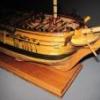
To check the lines I started to build a half model. For the frames I use 3mm birch plywood, it's for a model in 1/32 perhaps a little small, but I've had a bigger batch at home. All space between the frames I fill with poplar plywood. It's easy to shape but stable enough for the purpose.
I glue the drawngs with rubber cement on the ply woord
With a sharp knife I mark every 5' line. The picture shows frame 0:
All bulkheades and the center are cutted out. The hull has a length of around 1m, which is not as big compared with the new 1/200 model kits of the WWII battle ships.
-
 AnobiumPunctatum got a reaction from PeteB in HM Cutter Cheerful 1806 by Chuck - FINISHED - 1:48 scale - kit prototype
Chuck, it's always a pleasure to follow your logs.
-
AnobiumPunctatum got a reaction from Eddie in HM Sloop Fly by AnobiumPunctatum - 1:32 - POF
Greg,
I don't have a CNC mill. I use a simple mill with a coordinate table.
I work a lot with the PC during my job and so I thought also of using a CNC for model building - there are some interesting kits in the internet. But than I thought it will be much more satisfactory to build the model by hand. It's completely different to what I do in my job and so it is a big challenge which I like.
I know that I will have imperfections, but this is what a model makes individual and interesting. Also the old time modelers and shipbuilders build their ships manual. So why not to do the same?
-
 AnobiumPunctatum got a reaction from Canute in HM Cutter Cheerful 1806 by Chuck - FINISHED - 1:48 scale - kit prototype
Chuck, it's always a pleasure to follow your logs.
-
 AnobiumPunctatum got a reaction from WackoWolf in HM Cutter Cheerful 1806 by Chuck - FINISHED - 1:48 scale - kit prototype
Chuck, it's always a pleasure to follow your logs.
-
AnobiumPunctatum reacted to G.L. in HMS Triton cross section - FINISHED - by G.L. Scale 1:24
On the plans, no limber holes are marked. I although think that they existed, so I make them, hoping that they are correct.
-
 AnobiumPunctatum got a reaction from michael mott in HM Sloop Fly by AnobiumPunctatum - 1:32 - POF
Greg,
I don't have a CNC mill. I use a simple mill with a coordinate table.
I work a lot with the PC during my job and so I thought also of using a CNC for model building - there are some interesting kits in the internet. But than I thought it will be much more satisfactory to build the model by hand. It's completely different to what I do in my job and so it is a big challenge which I like.
I know that I will have imperfections, but this is what a model makes individual and interesting. Also the old time modelers and shipbuilders build their ships manual. So why not to do the same?
-
 AnobiumPunctatum got a reaction from Jack12477 in HM Cutter Cheerful 1806 by Chuck - FINISHED - 1:48 scale - kit prototype
Chuck, it's always a pleasure to follow your logs.
-
AnobiumPunctatum reacted to Chuck in HM Cutter Cheerful 1806 by Chuck - FINISHED - 1:48 scale - kit prototype
Thank You guys.
The thimbles are made from thin wall brass tube. In this case 1.5 mm brass tube. I tap them with a blunt point as shown in this image. Not to hard. The brass is soft and the thimbles will tear. They will also stretch larger in dia. and become thinner than you cut the original length.
Here are some close ups of my thimbles thus far in use on the model. Also note the thimble not yet punched to flare its ends in that first photo. See how much longer and smaller it is. Hooks are shaped from 26 gauge black wire.
Chuck
-
AnobiumPunctatum reacted to dvm27 in HM Sloop Fly by AnobiumPunctatum - 1:32 - POF
I agree, Christian. The stern deadwood is more difficult and you have to match starboard and port sides prefectly, especially the positions of the steps. CNC would certainly make this easier!
-
AnobiumPunctatum reacted to albert in HM Sloop Fly by AnobiumPunctatum - 1:32 - POF
Beautiful work Christian.
-
 AnobiumPunctatum got a reaction from Mike 41 in HM Sloop Fly by AnobiumPunctatum - 1:32 - POF
Thanks very much for the likes and comments.
You are right, Greg. I have to sand this later down. I don't find a way to do this with my small mill and chisels.
There's much more to sand down.
I'am not sure what is more complicated, the stem ore the stern deadwood. I think the stern, because there are a lot of different steps to do and you have to think about every step, before you start. I made me a small list of all single steps and hope I've nothing forgotten.
-
AnobiumPunctatum got a reaction from Eddie in HM Sloop Fly by AnobiumPunctatum - 1:32 - POF
Next step is the after deadwood.
I made the components of different strong woods, to make the shapeing later easier. The center line was marked with small stencils and a small 1.5mm drill bit was used to set holes for small pins. The following photo shows the alignment of the lower part on the keel.
All components are put temporarily together
Before the components van be glued together, the upper Notches for the last parallel frames must be milled.
After assembly, the deadwood is supported from the back with small wood pieces to have a smooth and, above all, stable support during milling:
As final step the template will be cut out:
The last picture shows the deadwood after milling the starbord site
Next step will be the port side.
-
 AnobiumPunctatum got a reaction from Martin W in HM Sloop Fly by AnobiumPunctatum - 1:32 - POF
Thanks very much for the likes and comments.
You are right, Greg. I have to sand this later down. I don't find a way to do this with my small mill and chisels.
There's much more to sand down.
I'am not sure what is more complicated, the stem ore the stern deadwood. I think the stern, because there are a lot of different steps to do and you have to think about every step, before you start. I made me a small list of all single steps and hope I've nothing forgotten.
-
 AnobiumPunctatum got a reaction from davec in HM Sloop Fly by AnobiumPunctatum - 1:32 - POF
Next step is the after deadwood.
I made the components of different strong woods, to make the shapeing later easier. The center line was marked with small stencils and a small 1.5mm drill bit was used to set holes for small pins. The following photo shows the alignment of the lower part on the keel.
All components are put temporarily together
Before the components van be glued together, the upper Notches for the last parallel frames must be milled.
After assembly, the deadwood is supported from the back with small wood pieces to have a smooth and, above all, stable support during milling:
As final step the template will be cut out:
The last picture shows the deadwood after milling the starbord site
Next step will be the port side.
-
AnobiumPunctatum reacted to dvm27 in HM Sloop Fly by AnobiumPunctatum - 1:32 - POF
Outstanding, Christian. Looks like you've left well in excess of 3" on those steps.I can't tell from your photograph but the aft deadwood above the bearding line should taper to 10" at the stern deadwood.See TFFM 1.23.
-
 AnobiumPunctatum got a reaction from EdT in HM Sloop Fly by AnobiumPunctatum - 1:32 - POF
Next step is the after deadwood.
I made the components of different strong woods, to make the shapeing later easier. The center line was marked with small stencils and a small 1.5mm drill bit was used to set holes for small pins. The following photo shows the alignment of the lower part on the keel.
All components are put temporarily together
Before the components van be glued together, the upper Notches for the last parallel frames must be milled.
After assembly, the deadwood is supported from the back with small wood pieces to have a smooth and, above all, stable support during milling:
As final step the template will be cut out:
The last picture shows the deadwood after milling the starbord site
Next step will be the port side.
-
 AnobiumPunctatum got a reaction from Archi in HM Sloop Fly by AnobiumPunctatum - 1:32 - POF
Next step is the after deadwood.
I made the components of different strong woods, to make the shapeing later easier. The center line was marked with small stencils and a small 1.5mm drill bit was used to set holes for small pins. The following photo shows the alignment of the lower part on the keel.
All components are put temporarily together
Before the components van be glued together, the upper Notches for the last parallel frames must be milled.
After assembly, the deadwood is supported from the back with small wood pieces to have a smooth and, above all, stable support during milling:
As final step the template will be cut out:
The last picture shows the deadwood after milling the starbord site
Next step will be the port side.
-
 AnobiumPunctatum got a reaction from zoly99sask in HM Sloop Fly by AnobiumPunctatum - 1:32 - POF
Next step is the after deadwood.
I made the components of different strong woods, to make the shapeing later easier. The center line was marked with small stencils and a small 1.5mm drill bit was used to set holes for small pins. The following photo shows the alignment of the lower part on the keel.
All components are put temporarily together
Before the components van be glued together, the upper Notches for the last parallel frames must be milled.
After assembly, the deadwood is supported from the back with small wood pieces to have a smooth and, above all, stable support during milling:
As final step the template will be cut out:
The last picture shows the deadwood after milling the starbord site
Next step will be the port side.
-
 AnobiumPunctatum got a reaction from Engelmann in HM Sloop Fly by AnobiumPunctatum - 1:32 - POF
Next step is the after deadwood.
I made the components of different strong woods, to make the shapeing later easier. The center line was marked with small stencils and a small 1.5mm drill bit was used to set holes for small pins. The following photo shows the alignment of the lower part on the keel.
All components are put temporarily together
Before the components van be glued together, the upper Notches for the last parallel frames must be milled.
After assembly, the deadwood is supported from the back with small wood pieces to have a smooth and, above all, stable support during milling:
As final step the template will be cut out:
The last picture shows the deadwood after milling the starbord site
Next step will be the port side.
-
AnobiumPunctatum got a reaction from Eddie in HM Sloop Fly by AnobiumPunctatum - 1:32 - POF
After a Long time I can Show new Progress of the build of my Sloop. After the stem I started building the lower and upper apron. Especially the lower apron, was really difficult. I need three trys until I get an result which I decided to use for my build. I think that I wouldn't get it better. I accent all glueing joints with brown color. After finishing the stem looks as in the following picture: David Shows in his book a simplified method for Building the rising woodI decided to follow the more detailed way, because I have a very precise Position of every second Frame. I think that this will help me in the future. I used this simple dummy frame during the build for checking the wide of the notches
Next step will be the after deadwood.
-
AnobiumPunctatum got a reaction from Mike 41 in HM Sloop Fly by AnobiumPunctatum - 1:32 - POF
Next step is the after deadwood.
I made the components of different strong woods, to make the shapeing later easier. The center line was marked with small stencils and a small 1.5mm drill bit was used to set holes for small pins. The following photo shows the alignment of the lower part on the keel.
All components are put temporarily together
Before the components van be glued together, the upper Notches for the last parallel frames must be milled.
After assembly, the deadwood is supported from the back with small wood pieces to have a smooth and, above all, stable support during milling:
As final step the template will be cut out:
The last picture shows the deadwood after milling the starbord site
Next step will be the port side.
-
 AnobiumPunctatum got a reaction from Mike Y in HM Sloop Fly by AnobiumPunctatum - 1:32 - POF
Next step is the after deadwood.
I made the components of different strong woods, to make the shapeing later easier. The center line was marked with small stencils and a small 1.5mm drill bit was used to set holes for small pins. The following photo shows the alignment of the lower part on the keel.
All components are put temporarily together
Before the components van be glued together, the upper Notches for the last parallel frames must be milled.
After assembly, the deadwood is supported from the back with small wood pieces to have a smooth and, above all, stable support during milling:
As final step the template will be cut out:
The last picture shows the deadwood after milling the starbord site
Next step will be the port side.
-
 AnobiumPunctatum got a reaction from tlevine in HM Sloop Fly by AnobiumPunctatum - 1:32 - POF
Next step is the after deadwood.
I made the components of different strong woods, to make the shapeing later easier. The center line was marked with small stencils and a small 1.5mm drill bit was used to set holes for small pins. The following photo shows the alignment of the lower part on the keel.
All components are put temporarily together
Before the components van be glued together, the upper Notches for the last parallel frames must be milled.
After assembly, the deadwood is supported from the back with small wood pieces to have a smooth and, above all, stable support during milling:
As final step the template will be cut out:
The last picture shows the deadwood after milling the starbord site
Next step will be the port side.
-
AnobiumPunctatum got a reaction from Martin W in HM Sloop Fly by AnobiumPunctatum - 1:32 - POF
Next step is the after deadwood.
I made the components of different strong woods, to make the shapeing later easier. The center line was marked with small stencils and a small 1.5mm drill bit was used to set holes for small pins. The following photo shows the alignment of the lower part on the keel.
All components are put temporarily together
Before the components van be glued together, the upper Notches for the last parallel frames must be milled.
After assembly, the deadwood is supported from the back with small wood pieces to have a smooth and, above all, stable support during milling:
As final step the template will be cut out:
The last picture shows the deadwood after milling the starbord site
Next step will be the port side.