
Supplies of the Ship Modeler's Handbook are running out. Get your copy NOW before they are gone! Click on photo to order.
×


AnobiumPunctatum
-
Posts
1,269 -
Joined
-
Last visited
Reputation Activity
-

 AnobiumPunctatum got a reaction from Saburo in Naval Cutter Alert by AnobiumPuncatum - Scale 1/36 - POF
After the drawing works it was time to make sawdust.
First part is the keel, which is a little bit tricky. The keel has a light curvature and the joints are perpendicular to the base line.
I cut some small stripes with my cirular saw, make the joints and glue the parts together. Next I added the parts for the stem.
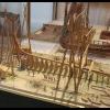
The picture shows the step on the building board. I use Tamiya Tape to avoid that the keel glues on the paper during the build.
The next pictures show the complete assembled backbone for the small vessel,
the stem with with the changed layout of the parts,
the keel and the rising wood,
and the stern post with the after deadwood.
The next steps are cutting the rabbet, the keelson and the building board. Then I can start with the frames.
-
AnobiumPunctatum reacted to Bugra in Naval Cutter Alert by AnobiumPuncatum - Scale 1/36 - POF
Very interesting.. And excellent drawing skills I see.. Congratulations Christian. I'll be watching this log..
Cheers, Bugra.
-
 AnobiumPunctatum got a reaction from Force9 in USS Constitution by Force9 - Revell - PLASTIC - Revisiting the classic 1/96 kit
I found your log this morning. A really wonderful build.
-
AnobiumPunctatum reacted to Erebus and Terror in HMS Terror by Erebus and Terror - FINISHED - Scale 1:48 - POB - as fitted for polar service in 1845
BOXING SCARPH
This section represents the final piece of the keel for my model and was the most difficult to make. I temporarily glued a paper template to the swiss pear blank, then I cut it out with a mini table saw and scroll saw. I sanded the piece to the precise dimensions using a spindle sander and modeler’s files. The box scarph was carved by hand using a small chisel, and then scraped flat with a razor blade. Like the rest of the keel, I lined the boxing with vellum to simulate tarred flannel.
Cutting the aft part of the keel section.
Chiseling out the box scarph.
Finished scarph compared to plans.
Plain scarph at aft of keel section.
Gluing the vellum in place.
Vellum trimmed to fit.
Finished box scarph.
Section glued to the rest of keel.
-
AnobiumPunctatum reacted to samueljr in 18th Century Longboat by samueljr - FINISHED
Well getting closer to completion.........
Shrouds, anchor and touch-up left
Sam
-
AnobiumPunctatum reacted to samueljr in 18th Century Longboat by samueljr - FINISHED
That I'd post a few more progress pics.
It's really just straight from the manual building at this point.
Sam
-
AnobiumPunctatum reacted to firdajan in Revenge by firdajan - FINISHED - Shipyard - CARD - (1577) 1:96
First part of running rigging is completed. Now I have to prepare sails and sew them.
Anchors are finished - just hang up them.
Enjoy pictures
Jan
-
AnobiumPunctatum reacted to archjofo in Naval Cutter Alert by AnobiumPuncatum - Scale 1/36 - POF
Hello Christian,
really very neat and accurate drawings.
Since you can build a nice model.
-
 AnobiumPunctatum got a reaction from Doreltomin in Naval Cutter Alert by AnobiumPuncatum - Scale 1/36 - POF
@all
Thanks for your replays and likes
@Marcus
Nice to hear from you. I hope everything is ok.
-
AnobiumPunctatum got a reaction from Saburo in Naval Cutter Alert by AnobiumPuncatum - Scale 1/36 - POF
I was really suprised that I did not find a build log about the Naval Cutter Alert on MSW 2.0. I know that there exist some pictures of a model on the old MSW
The first source for building a model of this small vessel are Peter Goodwins book "The Naval Cutter Alert, 1777", published by PhoenixPublications Inc. 1991 and the two original drawing of her sister Rattlesnake (1776) which you will find on the homepage of the NMM.
There also exist two paintings of Joseph Marshall of the ship, which are exhibited in the Science Museum, London.
I found also an Sheer and Profile drawing of Alert which was published by the NRG.
The sheer and profile of the NRG and Goodwin differ from the original drawing. They show the maximum width of the ship not at frame 0. Perhaps my Engish is to bad, but I could not find any reason for this. So I decide to draw my own lines. which were based on Goodwin and the original drawing.
The drawing is not finished, because I decided only to draw what I need for my build.
Next step was the keel. Goodwin shows for the pass between keel and lower apron a solution which I could not find on any original cutter drawings.
For the after deadwood he does not offer any possible solution
I decide to follow the original drawing of Cheerful 1806 for the pass between keel and lower apron. The flat joint at the foremost keel part is shown on original drawings of this period (for example on HMS Triton). For the after deadwood I decided to use a bearing line. I am not sure if this is common for ships of this period.
The next picture shows my completed keel drawing:
Goodwin uses for his design the common frameing pattern of double and single frames. I am not sure that this design was used for the original ship. For the Swan class sloops only single frames were used. This you will also find on the drawing of Cheerful and other cutters. Also the wide of the frame parts are not clear. In his drawing he uses much smaller futtocks than he descibed in the text part of the book. In his "Construction and Fitting of Sailing Man of War" he gives a third solution.
What now? Alert is a practice model for me to get the experience to continue my HMS Fly build. Marshall shows on his paintings an simplified frameing design, so I decided to use this. Every frame is 8'' width followed by 8'' space. For the port side I like to show the clinker planking.
On my drawing the final design for the last frame and the hawse pieces is missing in the moment.
The drawings for every 31frames and 21cant frames are finished.
I am not sure in the moment if I will use the original practice with chocks or the simplified method of Harold Hahn for my build.
It will be very nice if you have further information about the cutters of this time. I found the Marmaduke Stalkartt on Google-books, but they didn't scan the plates. Perhaps one of the MSW user can help me to confirm my decisions.
-
 AnobiumPunctatum got a reaction from CiscoH in Naval Cutter Alert by AnobiumPuncatum - Scale 1/36 - POF
I was really suprised that I did not find a build log about the Naval Cutter Alert on MSW 2.0. I know that there exist some pictures of a model on the old MSW
The first source for building a model of this small vessel are Peter Goodwins book "The Naval Cutter Alert, 1777", published by PhoenixPublications Inc. 1991 and the two original drawing of her sister Rattlesnake (1776) which you will find on the homepage of the NMM.
There also exist two paintings of Joseph Marshall of the ship, which are exhibited in the Science Museum, London.
I found also an Sheer and Profile drawing of Alert which was published by the NRG.
The sheer and profile of the NRG and Goodwin differ from the original drawing. They show the maximum width of the ship not at frame 0. Perhaps my Engish is to bad, but I could not find any reason for this. So I decide to draw my own lines. which were based on Goodwin and the original drawing.
The drawing is not finished, because I decided only to draw what I need for my build.
Next step was the keel. Goodwin shows for the pass between keel and lower apron a solution which I could not find on any original cutter drawings.
For the after deadwood he does not offer any possible solution
I decide to follow the original drawing of Cheerful 1806 for the pass between keel and lower apron. The flat joint at the foremost keel part is shown on original drawings of this period (for example on HMS Triton). For the after deadwood I decided to use a bearing line. I am not sure if this is common for ships of this period.
The next picture shows my completed keel drawing:
Goodwin uses for his design the common frameing pattern of double and single frames. I am not sure that this design was used for the original ship. For the Swan class sloops only single frames were used. This you will also find on the drawing of Cheerful and other cutters. Also the wide of the frame parts are not clear. In his drawing he uses much smaller futtocks than he descibed in the text part of the book. In his "Construction and Fitting of Sailing Man of War" he gives a third solution.
What now? Alert is a practice model for me to get the experience to continue my HMS Fly build. Marshall shows on his paintings an simplified frameing design, so I decided to use this. Every frame is 8'' width followed by 8'' space. For the port side I like to show the clinker planking.
On my drawing the final design for the last frame and the hawse pieces is missing in the moment.
The drawings for every 31frames and 21cant frames are finished.
I am not sure in the moment if I will use the original practice with chocks or the simplified method of Harold Hahn for my build.
It will be very nice if you have further information about the cutters of this time. I found the Marmaduke Stalkartt on Google-books, but they didn't scan the plates. Perhaps one of the MSW user can help me to confirm my decisions.
-
 AnobiumPunctatum got a reaction from tadheus in Naval Cutter Alert by AnobiumPuncatum - Scale 1/36 - POF
I was really suprised that I did not find a build log about the Naval Cutter Alert on MSW 2.0. I know that there exist some pictures of a model on the old MSW
The first source for building a model of this small vessel are Peter Goodwins book "The Naval Cutter Alert, 1777", published by PhoenixPublications Inc. 1991 and the two original drawing of her sister Rattlesnake (1776) which you will find on the homepage of the NMM.
There also exist two paintings of Joseph Marshall of the ship, which are exhibited in the Science Museum, London.
I found also an Sheer and Profile drawing of Alert which was published by the NRG.
The sheer and profile of the NRG and Goodwin differ from the original drawing. They show the maximum width of the ship not at frame 0. Perhaps my Engish is to bad, but I could not find any reason for this. So I decide to draw my own lines. which were based on Goodwin and the original drawing.
The drawing is not finished, because I decided only to draw what I need for my build.
Next step was the keel. Goodwin shows for the pass between keel and lower apron a solution which I could not find on any original cutter drawings.
For the after deadwood he does not offer any possible solution
I decide to follow the original drawing of Cheerful 1806 for the pass between keel and lower apron. The flat joint at the foremost keel part is shown on original drawings of this period (for example on HMS Triton). For the after deadwood I decided to use a bearing line. I am not sure if this is common for ships of this period.
The next picture shows my completed keel drawing:
Goodwin uses for his design the common frameing pattern of double and single frames. I am not sure that this design was used for the original ship. For the Swan class sloops only single frames were used. This you will also find on the drawing of Cheerful and other cutters. Also the wide of the frame parts are not clear. In his drawing he uses much smaller futtocks than he descibed in the text part of the book. In his "Construction and Fitting of Sailing Man of War" he gives a third solution.
What now? Alert is a practice model for me to get the experience to continue my HMS Fly build. Marshall shows on his paintings an simplified frameing design, so I decided to use this. Every frame is 8'' width followed by 8'' space. For the port side I like to show the clinker planking.
On my drawing the final design for the last frame and the hawse pieces is missing in the moment.
The drawings for every 31frames and 21cant frames are finished.
I am not sure in the moment if I will use the original practice with chocks or the simplified method of Harold Hahn for my build.
It will be very nice if you have further information about the cutters of this time. I found the Marmaduke Stalkartt on Google-books, but they didn't scan the plates. Perhaps one of the MSW user can help me to confirm my decisions.
-
 AnobiumPunctatum got a reaction from albert in Naval Cutter Alert by AnobiumPuncatum - Scale 1/36 - POF
I was really suprised that I did not find a build log about the Naval Cutter Alert on MSW 2.0. I know that there exist some pictures of a model on the old MSW
The first source for building a model of this small vessel are Peter Goodwins book "The Naval Cutter Alert, 1777", published by PhoenixPublications Inc. 1991 and the two original drawing of her sister Rattlesnake (1776) which you will find on the homepage of the NMM.
There also exist two paintings of Joseph Marshall of the ship, which are exhibited in the Science Museum, London.
I found also an Sheer and Profile drawing of Alert which was published by the NRG.
The sheer and profile of the NRG and Goodwin differ from the original drawing. They show the maximum width of the ship not at frame 0. Perhaps my Engish is to bad, but I could not find any reason for this. So I decide to draw my own lines. which were based on Goodwin and the original drawing.
The drawing is not finished, because I decided only to draw what I need for my build.
Next step was the keel. Goodwin shows for the pass between keel and lower apron a solution which I could not find on any original cutter drawings.
For the after deadwood he does not offer any possible solution
I decide to follow the original drawing of Cheerful 1806 for the pass between keel and lower apron. The flat joint at the foremost keel part is shown on original drawings of this period (for example on HMS Triton). For the after deadwood I decided to use a bearing line. I am not sure if this is common for ships of this period.
The next picture shows my completed keel drawing:
Goodwin uses for his design the common frameing pattern of double and single frames. I am not sure that this design was used for the original ship. For the Swan class sloops only single frames were used. This you will also find on the drawing of Cheerful and other cutters. Also the wide of the frame parts are not clear. In his drawing he uses much smaller futtocks than he descibed in the text part of the book. In his "Construction and Fitting of Sailing Man of War" he gives a third solution.
What now? Alert is a practice model for me to get the experience to continue my HMS Fly build. Marshall shows on his paintings an simplified frameing design, so I decided to use this. Every frame is 8'' width followed by 8'' space. For the port side I like to show the clinker planking.
On my drawing the final design for the last frame and the hawse pieces is missing in the moment.
The drawings for every 31frames and 21cant frames are finished.
I am not sure in the moment if I will use the original practice with chocks or the simplified method of Harold Hahn for my build.
It will be very nice if you have further information about the cutters of this time. I found the Marmaduke Stalkartt on Google-books, but they didn't scan the plates. Perhaps one of the MSW user can help me to confirm my decisions.
-
 AnobiumPunctatum got a reaction from JPZ66 in Naval Cutter Alert by AnobiumPuncatum - Scale 1/36 - POF
I was really suprised that I did not find a build log about the Naval Cutter Alert on MSW 2.0. I know that there exist some pictures of a model on the old MSW
The first source for building a model of this small vessel are Peter Goodwins book "The Naval Cutter Alert, 1777", published by PhoenixPublications Inc. 1991 and the two original drawing of her sister Rattlesnake (1776) which you will find on the homepage of the NMM.
There also exist two paintings of Joseph Marshall of the ship, which are exhibited in the Science Museum, London.
I found also an Sheer and Profile drawing of Alert which was published by the NRG.
The sheer and profile of the NRG and Goodwin differ from the original drawing. They show the maximum width of the ship not at frame 0. Perhaps my Engish is to bad, but I could not find any reason for this. So I decide to draw my own lines. which were based on Goodwin and the original drawing.
The drawing is not finished, because I decided only to draw what I need for my build.
Next step was the keel. Goodwin shows for the pass between keel and lower apron a solution which I could not find on any original cutter drawings.
For the after deadwood he does not offer any possible solution
I decide to follow the original drawing of Cheerful 1806 for the pass between keel and lower apron. The flat joint at the foremost keel part is shown on original drawings of this period (for example on HMS Triton). For the after deadwood I decided to use a bearing line. I am not sure if this is common for ships of this period.
The next picture shows my completed keel drawing:
Goodwin uses for his design the common frameing pattern of double and single frames. I am not sure that this design was used for the original ship. For the Swan class sloops only single frames were used. This you will also find on the drawing of Cheerful and other cutters. Also the wide of the frame parts are not clear. In his drawing he uses much smaller futtocks than he descibed in the text part of the book. In his "Construction and Fitting of Sailing Man of War" he gives a third solution.
What now? Alert is a practice model for me to get the experience to continue my HMS Fly build. Marshall shows on his paintings an simplified frameing design, so I decided to use this. Every frame is 8'' width followed by 8'' space. For the port side I like to show the clinker planking.
On my drawing the final design for the last frame and the hawse pieces is missing in the moment.
The drawings for every 31frames and 21cant frames are finished.
I am not sure in the moment if I will use the original practice with chocks or the simplified method of Harold Hahn for my build.
It will be very nice if you have further information about the cutters of this time. I found the Marmaduke Stalkartt on Google-books, but they didn't scan the plates. Perhaps one of the MSW user can help me to confirm my decisions.
-
 AnobiumPunctatum got a reaction from robert miller in Naval Cutter Alert by AnobiumPuncatum - Scale 1/36 - POF
I was really suprised that I did not find a build log about the Naval Cutter Alert on MSW 2.0. I know that there exist some pictures of a model on the old MSW
The first source for building a model of this small vessel are Peter Goodwins book "The Naval Cutter Alert, 1777", published by PhoenixPublications Inc. 1991 and the two original drawing of her sister Rattlesnake (1776) which you will find on the homepage of the NMM.
There also exist two paintings of Joseph Marshall of the ship, which are exhibited in the Science Museum, London.
I found also an Sheer and Profile drawing of Alert which was published by the NRG.
The sheer and profile of the NRG and Goodwin differ from the original drawing. They show the maximum width of the ship not at frame 0. Perhaps my Engish is to bad, but I could not find any reason for this. So I decide to draw my own lines. which were based on Goodwin and the original drawing.
The drawing is not finished, because I decided only to draw what I need for my build.
Next step was the keel. Goodwin shows for the pass between keel and lower apron a solution which I could not find on any original cutter drawings.
For the after deadwood he does not offer any possible solution
I decide to follow the original drawing of Cheerful 1806 for the pass between keel and lower apron. The flat joint at the foremost keel part is shown on original drawings of this period (for example on HMS Triton). For the after deadwood I decided to use a bearing line. I am not sure if this is common for ships of this period.
The next picture shows my completed keel drawing:
Goodwin uses for his design the common frameing pattern of double and single frames. I am not sure that this design was used for the original ship. For the Swan class sloops only single frames were used. This you will also find on the drawing of Cheerful and other cutters. Also the wide of the frame parts are not clear. In his drawing he uses much smaller futtocks than he descibed in the text part of the book. In his "Construction and Fitting of Sailing Man of War" he gives a third solution.
What now? Alert is a practice model for me to get the experience to continue my HMS Fly build. Marshall shows on his paintings an simplified frameing design, so I decided to use this. Every frame is 8'' width followed by 8'' space. For the port side I like to show the clinker planking.
On my drawing the final design for the last frame and the hawse pieces is missing in the moment.
The drawings for every 31frames and 21cant frames are finished.
I am not sure in the moment if I will use the original practice with chocks or the simplified method of Harold Hahn for my build.
It will be very nice if you have further information about the cutters of this time. I found the Marmaduke Stalkartt on Google-books, but they didn't scan the plates. Perhaps one of the MSW user can help me to confirm my decisions.
-
 AnobiumPunctatum got a reaction from 42rocker in Triton (1:48) by kellrandy (Randall)
Randall,
these differences are quite normal. If you print out the parts on your deskjet, you will see that it makes a difference if you use landscape or portrait format.
They are very small (0.1) and are up to the manufacturing process of the paper. Another source of the porblem is the thikness of the line. If I remember right they are about 0.25mm. If you saw out a part and sand to the correct size, you see normally more than the half of the line.
0.25mm in sum are very small but if you glue more than one part together your get very quick a difference of 1 mm and more. I didn't count how many deadwoods I have casted off until I understand how to work with these problems:
Try to use allways the same paper and paper direction and sand your parts until the whole line is nearly invisble. And the rest is handcraft - so small differences are totally normal.
-
 AnobiumPunctatum got a reaction from Long9Ron in Triton (1:48) by kellrandy (Randall)
Randall,
these differences are quite normal. If you print out the parts on your deskjet, you will see that it makes a difference if you use landscape or portrait format.
They are very small (0.1) and are up to the manufacturing process of the paper. Another source of the porblem is the thikness of the line. If I remember right they are about 0.25mm. If you saw out a part and sand to the correct size, you see normally more than the half of the line.
0.25mm in sum are very small but if you glue more than one part together your get very quick a difference of 1 mm and more. I didn't count how many deadwoods I have casted off until I understand how to work with these problems:
Try to use allways the same paper and paper direction and sand your parts until the whole line is nearly invisble. And the rest is handcraft - so small differences are totally normal.
-
AnobiumPunctatum reacted to JSGerson in Rattlesnake by JSGerson - FINISHED - Mamoli - 1:64 - Using Robert Hunt’s practicum
Final Assembly
-
AnobiumPunctatum reacted to JSGerson in Rattlesnake by JSGerson - FINISHED - Mamoli - 1:64 - Using Robert Hunt’s practicum
As anyone can see, this planking job leaves a bit to be desired, but there it is. If I were to do it again hopefully it would be better.
Tree Nails
The tree nails are lined up along the bulkheads, two treenails per width of the plank. At the butt joints the tree nails are staggered.
End of Chapter 4
-
AnobiumPunctatum reacted to woodrat in USF Essex by woodrat - FINISHED - Scale 1:64 - Fully Framed - from Portia Takakjian plans
the quarter gallery lights were wrong, so I redid them. boarding steps.
-
AnobiumPunctatum reacted to woodrat in USF Essex by woodrat - FINISHED - Scale 1:64 - Fully Framed - from Portia Takakjian plans
The following shows the steps of the construction of the double wheel. The wood is jarrah.
turning the wheel on the Unimat
spokes
spokes in place
drum being machined
brass facing cut from sheet brass
-
AnobiumPunctatum reacted to druxey in Books Books Books?!!!
If it's British naval armament history and extreme detail you want, and have deep pockets, the two volumes by Adrian Caruana are the ultimate in this field.
-
 AnobiumPunctatum got a reaction from harvey1847 in HMS Triton 1773. POF. 1:48. Daniel
Hi Daniel,
everything works well. My drawings for the Alert are nearly finshed and I started the build yesterday. My next drawing project will be HMS Triton with single frames. But now I am happy that I can work with timber again.
-
AnobiumPunctatum reacted to harvey1847 in HMS Triton 1773. POF. 1:48. Daniel
Good night!
A small update. Just two pics. One about the lower deck clamp and the other about the thick stuff amidship.
Best wishes and happy happy days!
Daniel.
-
AnobiumPunctatum reacted to twintrow in 1/48th scale figures
A few of us have used the tank crew set I think from Tamiya 1/48th. The poses work well for ships crew. Only minor modifications. Should be available on line or most Hobby Shops. Photo shows a couple on my Fair American. Just painted, already in a good pose. See Helmsman and crew member working on the cannon.
Tom