HOLIDAY DONATION DRIVE - SUPPORT MSW - DO YOUR PART TO KEEP THIS GREAT FORUM GOING! (Only 13 donations so far - C'mon guys!)
×


DaveBaxt
-
Posts
1,324 -
Joined
-
Last visited
Content Type
Profiles
Forums
Gallery
Events
Everything posted by DaveBaxt
-
Thank you Andrew
-
Cheers Sam I am using a general purpose solder and flux paste which came with the torch . I think it has a very low melting point as as soon as I touch it to the work surface iit is melting but not running around . The solder is sticking to the 1mm brass rod but not the brass tube. I am not sure where I am going wrong. Perhaps the brass tube is at fault. My torch worked fine when I soldered the chain plates using silver solder paste.
-
Thank you Derek. I always appreciate your input.
-
Thank you Sam. Actually I tried to solder the joints but for some reason I could not get the solder to take to the brass tube even sfter using wire wool and pickling. I can only assume I did not get enough heat using a small gas torch using lighter fuel. Butane I think. So I ended up using epoxy cement which seemed to work fine, although I am disapointed I could not getthe soldering to work. Perhaps I need a larger torch or perhaps a different type of solder. The book I referenced all my sizes throughout this build has been James Lees 'The masting and rigging of English ships of War' Although for general layout I have used History of Ship models by Mondfeld as well. Hope this helps Dave
-
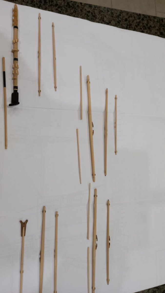
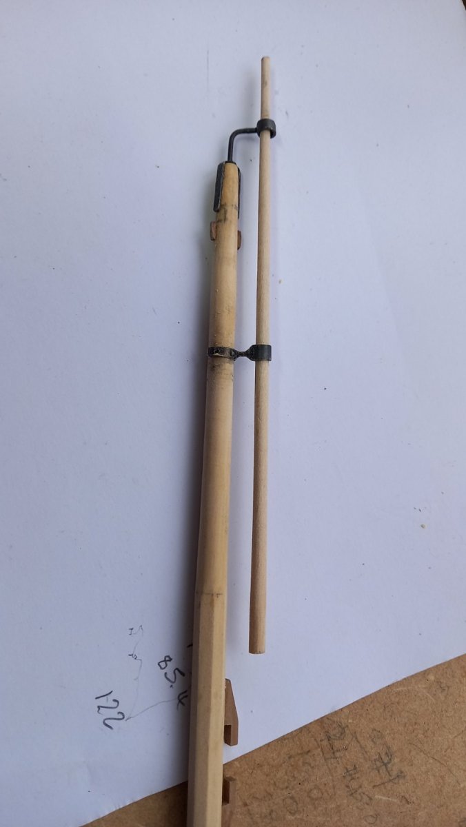
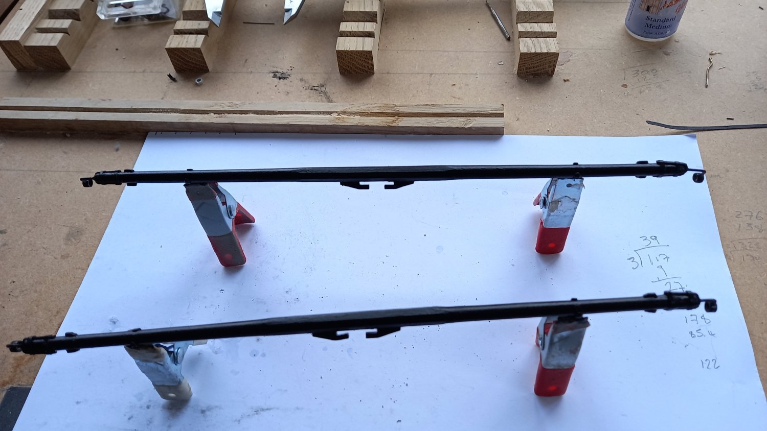
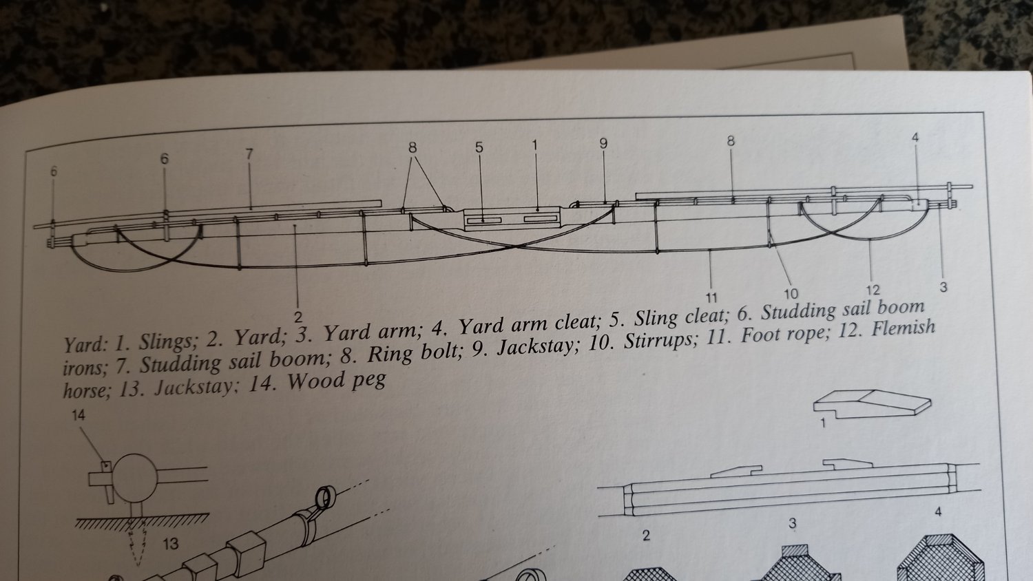
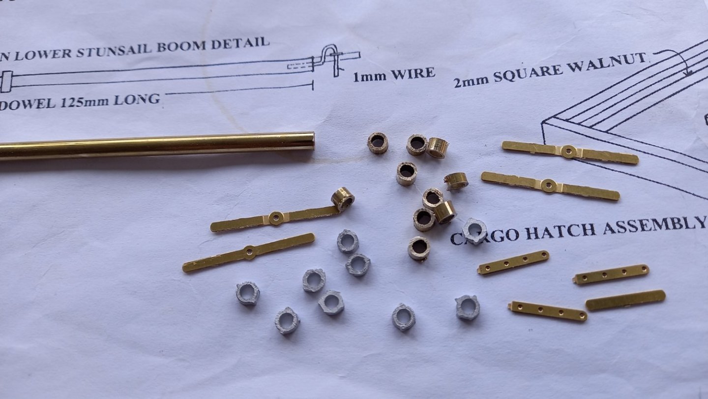
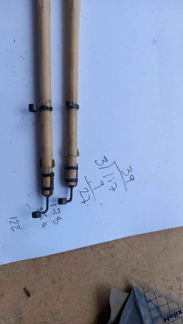
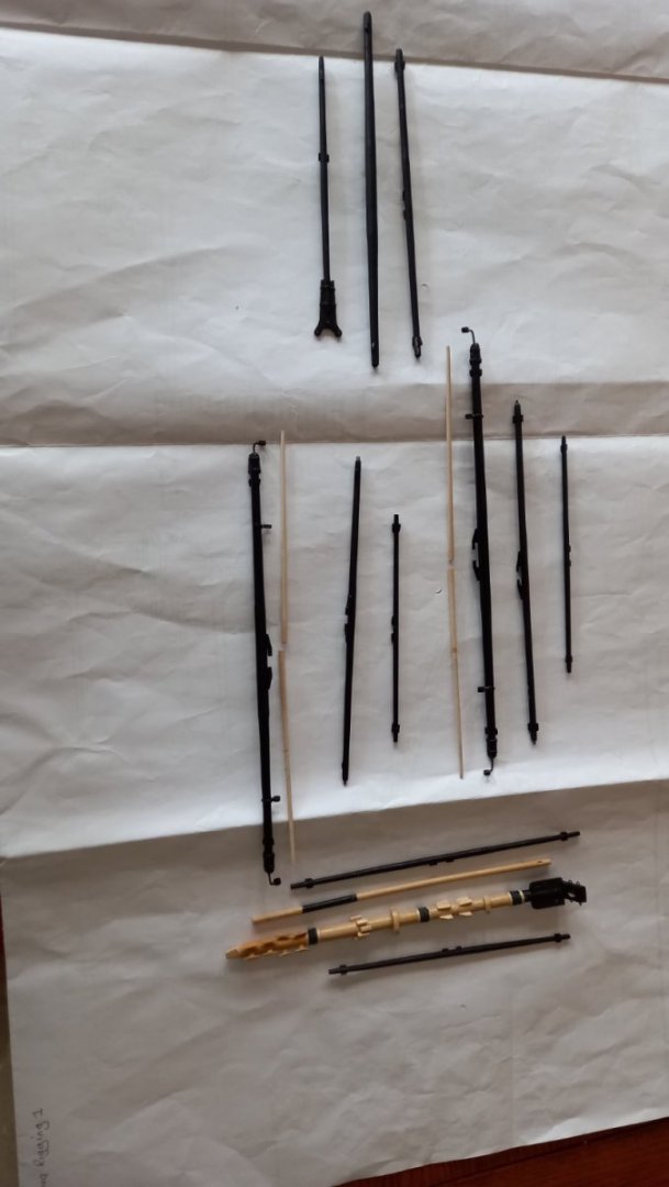
I have made some progress with the yards. Making the stunsail boom irons out of brass tube and 1 mm brass wire for the lower main and fore masts. I still need to fit the blocks, stirups and flemish horses to them for completion. I used strips of black card supplied by the kit for the boom iron staps. I still need to fit the lower stunsail booms to the outside of the main mast channels. Unfortunately still slow progress due to other comitments.


-
Nice job on what looks like a very fiddly piece . Your Diana is definately taking shape. Truely awe inspiring. Hope you enjoyed your break to Iceland. I was wondering where you had got too! Haha.
- 310 replies
-
- 1
-

-
- Diana
- Caldercraft
- (and 1 more)
-
Great Price too. Although I am a relative beginner All my machine tools are Proxxon. No complaints so far.,
-
As Always Derek I am amazed at your level of workmanship and something we can hopefully aspire to. Great looking workshop and garage. I too have expnded and moved my machine tools into the garage,leaving more space in my shed for everything else. I look forward to seeing her when you are finished and wonder have you any future plans for what you build next. Perhaps another Vanguard model?
- 345 replies
-
- 1
-

-
- Duchess Of Kingston
- Vanguard Models
- (and 1 more)
-
You seem to be juggling quite a few balls at once. I look forward to your HMS Snake/Scylla when ever you get around to it. Best of luck with what you are doing now.
-
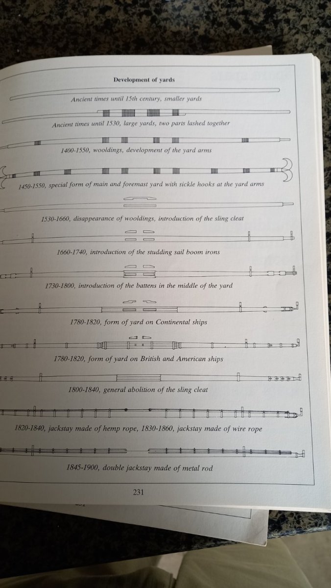
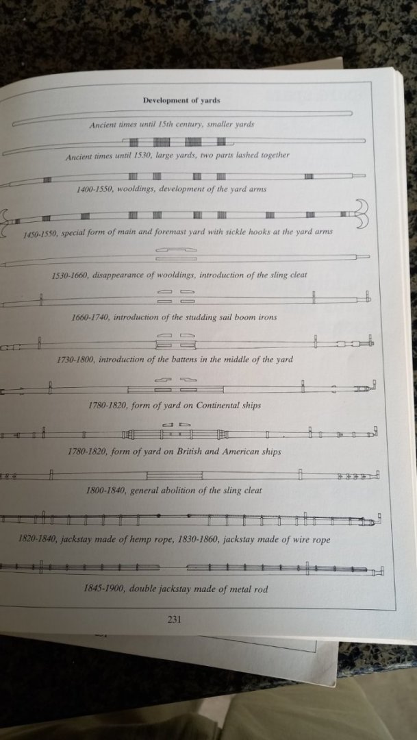
Ok thanks guys for your quick response but unfortunately I am still not getting it other than what I previously stated. Here is a couple of photos which I have taken of Mondfelds book 'Historic ship Models' I am not sure if the dates are correct for the above yards but we can see that at an earlier date there is what is clearly a section with a reduced diameter which is the yard arm (3) but at a later date there is a cleat instead of this yard arm. I am therefore assuming for the period I am concerned with ie 1758/61 when working out the length of the yard arm from Lees book ,The masting and rigging of warships' it is the length between the yard arm cleats and the end of the yard. Thank you once again for your help and please forgive me if I am not be too clear in what I am asking. Best regards Dave


-
Excellent workmanship and what seems like very quick work. I like the look of your workshop in the garden. What are you thinking of doing for your next project Andrew?
-
I have seen this term used a lot but finding it difficult to find out what a yard arm actually is. One explanation I have found is the tapered ends of the yards, however most information I can find clearly states that the yard is tapered throughout.( apart from the centre section )According to Mondfelds book. 'Historic ship models' there are clearly ends of the yard which have a change in section and wonder if this is the yard arm. Lees book refer to the length of the yard arm but does not show this change in section in the yard at the ends but a taoer throughout. I am also interested in the position of the cleats and wonder if this is where the yard arm starts and are used instead of the change in section. Sorry if this has been asked before but when putting in a search I am getting thousands of hits . Thank you again for peoples patience. Best regards Dave
-
Thank you for your input it is very much appreiciated..It looks like from Mondfeld drawing that adding Battens and increasing the diameter of the yard did not occur until 1780 on British ships which is after the Endeavour was built. Where as at an earlier period on continental ships it looks like the yard is made with the centre section octagonal and without the use of battens. I am still not convinced either way so might have to go with what Druxey has suggested and just leave the centre areas octagonal without the use of battens which is also what is in the Lees book and the AOTS book. So thank you for your input and for clearing that up in some way. Best regards Dave
-
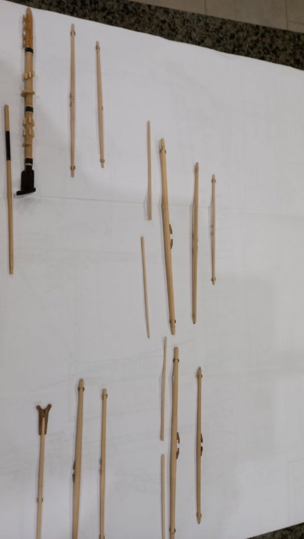
According to both Lees book 'The Masting and rigging of English ships of war' for the period the Endeavour 'was built with all lower yards and topsail yards were 8 squared ( octagon) except for the Crossjack yard which is 16 squared. The drawings for the above are also in the AOTS Endeavour and indicate the same. The topgallant yards are round throughout, as is the spritsail yard and the Sprit topsail yard . My question is this. After making the above yards from square boxwood stock and then sanding them into 8 sided throughout their length. I have then sanded them into 16 sided and then rounded and tapered to the ends. I have then left the centre sections as either 8 sided or 16 sided depending upon which yard I am making. ie Cross jack yard being 16 sided. So far so good although sanding a 16 sided on a 6mm spar does not look great. Now According to some blogs some people then add flat pieces of wood onto the middle section, but I am unsure if these are glued to the flats or glued to the round section if this is previously sanded round throughout. Hope this makes sense. I am unsure if the last precedure is only if people are using round stock for their yards in which therefore in my case there is no need to add these strips of wood to the already 8 or 16 sided centre section of the yards.in question? Best regards Dave
-
Unfortunately work has continued at a snails pace due to other comitments including gardening and other things non modeling activities. I have however managed to make a start on the yards but have come to a halt regarding the Fore, Main topgallant yards and whether or not they are round or are the same as the Topsail yard and the centre being left octagonal as are the lower fore,main and crossjack yard for the period of1758/61. According to James Lees book the Masting and rigging of English ships of war, page 15 it does say that the topgallant yards followed the pattern of the topsail yards so i am hoping this means that the centre section is left octangonal. Regarding the Spritsail yard this too is of the same as the topgallant yards ie 8 squaring but does not have the eyebolts on the ends.The centre of the Sprit Topsail Yard is also 8 squared . Regarding the the Crossjack yard for the period up to 1745 the yard was made round for its whole length and afterwards was of 16 sided and wondered if this is even possible to accurately make and have since found from the AOTS Endeavour has it as 8 sides octagonal. The Mizzen yard is to be left round for its whole length but not sure if this or the crossjack yard is fitted to the Endeavour . I clearly need to do a bit more research regarding the above yards. However if anyone has any thoughts or can enlighten me, it would be much appreciated. Best regards Dave
-
I look forward to the progress for this one as apart from something different, I sailed past her a few times from Aberdeen to Hull in my seafairing days. I am sure you will make a very fine job of this. Good luck.
-
To true Sam and thank you
-
I too think I will have to think about the door although it is electric and seals quite well. Also my shed which is where I will mainly be working is totally insulated and with a very small heated is nice and warm even at the coldest time of the year. I will just have to see how things go. Thanks again Andrew for the input.
-
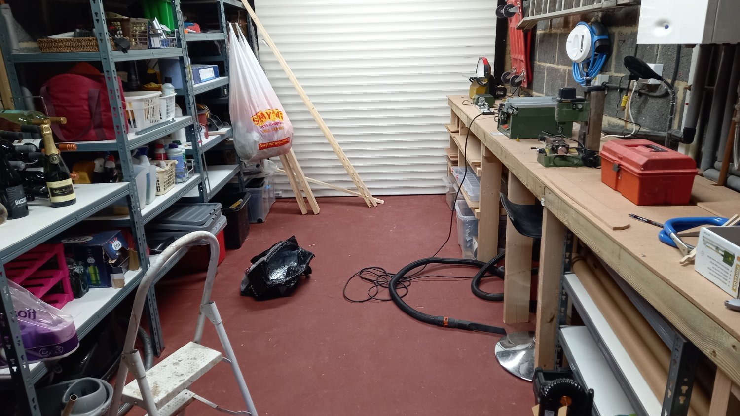
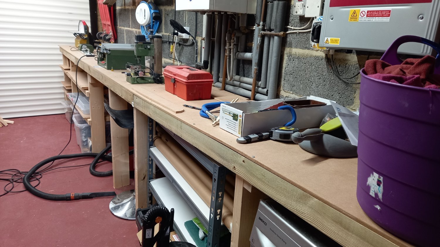
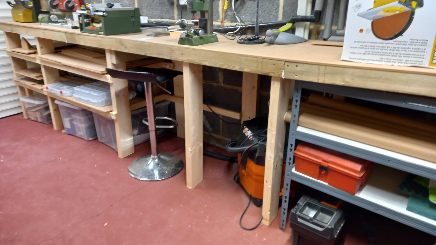
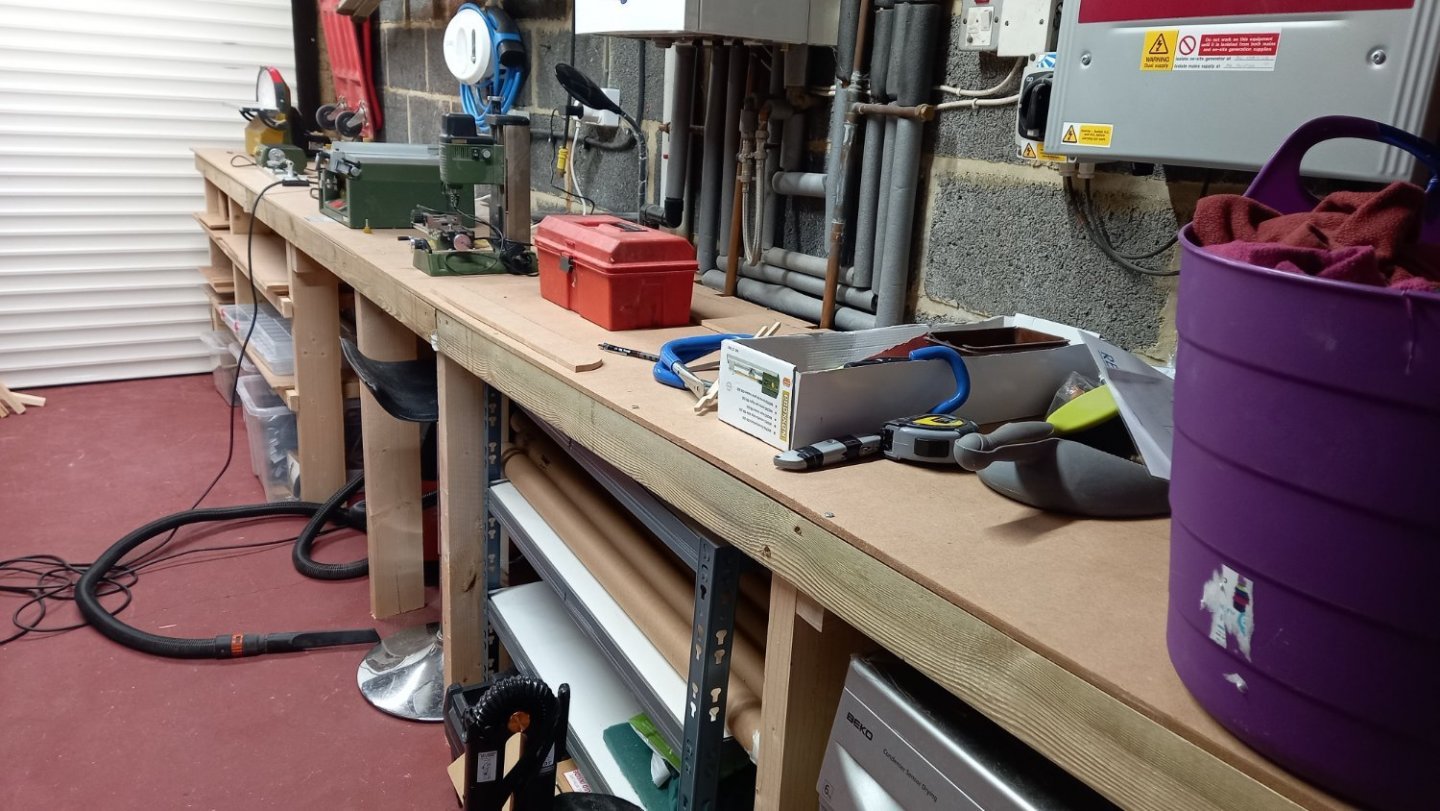
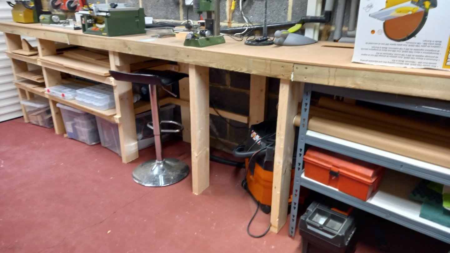
Its been a while since I last posted but not much to report regarding my Endeavour, however I have been planning for the future for when I build the HMS Diana. In the past I have used both my garden sheds as workshops but starting to find that as I have accumulated a number of machine tools it was beginning to be a bit cramped. As the HMS Diana is a a larger model I thought I would convert my garage into a workshop for the above said machine tools. Therefore leaving one of the sheds for garden equiment and the other for working on the model ship.( hand tools etc} I also have twice as much storage as I did before the upgrade. The most expensive part of the project was getting rid of the rubbish which had accumulated in the garage and loft for over 30 years. A job well done. I can now go back to my Endeavour but now that the finer weather is here, no doubt the Admiral will find some more distractions but hopefully I will be able to at least get some work done.

-
Wow. What fantastic photos of the ship not to mention the Cosmos. You clearly have a number of different Talents. Thank you for sharing them with us.
- 345 replies
-
- 2
-
-
-
- Duchess Of Kingston
- Vanguard Models
- (and 1 more)
-
Thanks Tony. I have manage to source some brass tube with the correct inside and outside diameter . But thanks for the link anyway. Always good to have options. Best regards Dave
-
Cheers Allan. I was not thinking of soldering these for the moment but now thinking of teplacing them with the brass.rod. If I can get my hands on some brass rod of the correct outside diameter . Although I have a small wood turning lathe I am hoping to be able to drill out the centre easily enough by stepping up dofferent diameter drills to eventially get the correct inside diameter for the stunsail boom. If I do end up using the castings I might end up drilling a hole in the side of the casting to take a 1 mm brass wire and glue the pieces together using approxy resin . Hopefully this will have sufficiant strength. I think I now have a couple of options which is great.
-
Thanks guys I had a feeling it was probably a no go. I think that is why I asked to be sure. I am not sure what the casting supplied with the kit os made of. Some kind of alloy and quite soft and easy to file/sand. Perhpas this is part alloy. I will see if I can soutce some brass tube of the same bore/diameter.and hopefully I can manage this instead. Telescope brass is readily available ,I am assuming this should solder ok Thanks to everyone for there quick responses, you have saved me a bit of time and frustration. Best regards Dave
-
Not sure I like the castings supplied for the stunsail boom brackets on my Endeavour. The kit suggests CA but as I have a few pieces of aluminium tubing I thought I could cut and drill sections and the hopfully solder using soldering paste the two parts together using a small butane torch. Is this aproach possible or is there a better aproach? I also intend to pickle everything for a few hours to remove any film from the componants and I am hoping this would work out ok on the aluminium before soldering .Best regards Dave
-
Great Idea Andrew and something I will try. Just wondering if people are having problems even with superior quality masking tapes? I apologise if i I have hijacked this thread.
- 42 replies
-
- 2
-
-
- vanguard models
- lady eleanor
- (and 3 more)