MORE HANDBOOKS ARE ON THEIR WAY! We will let you know when they get here.
×


jdbondy
-
Posts
338 -
Joined
-
Last visited
Content Type
Profiles
Forums
Gallery
Events
Everything posted by jdbondy
-
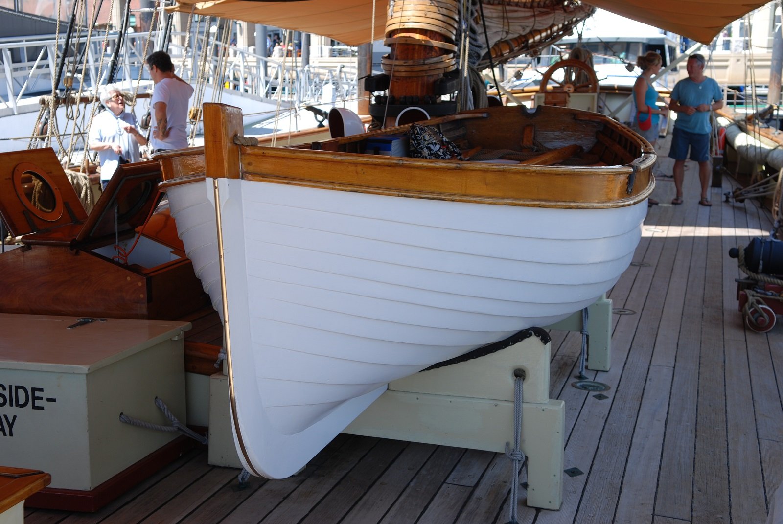
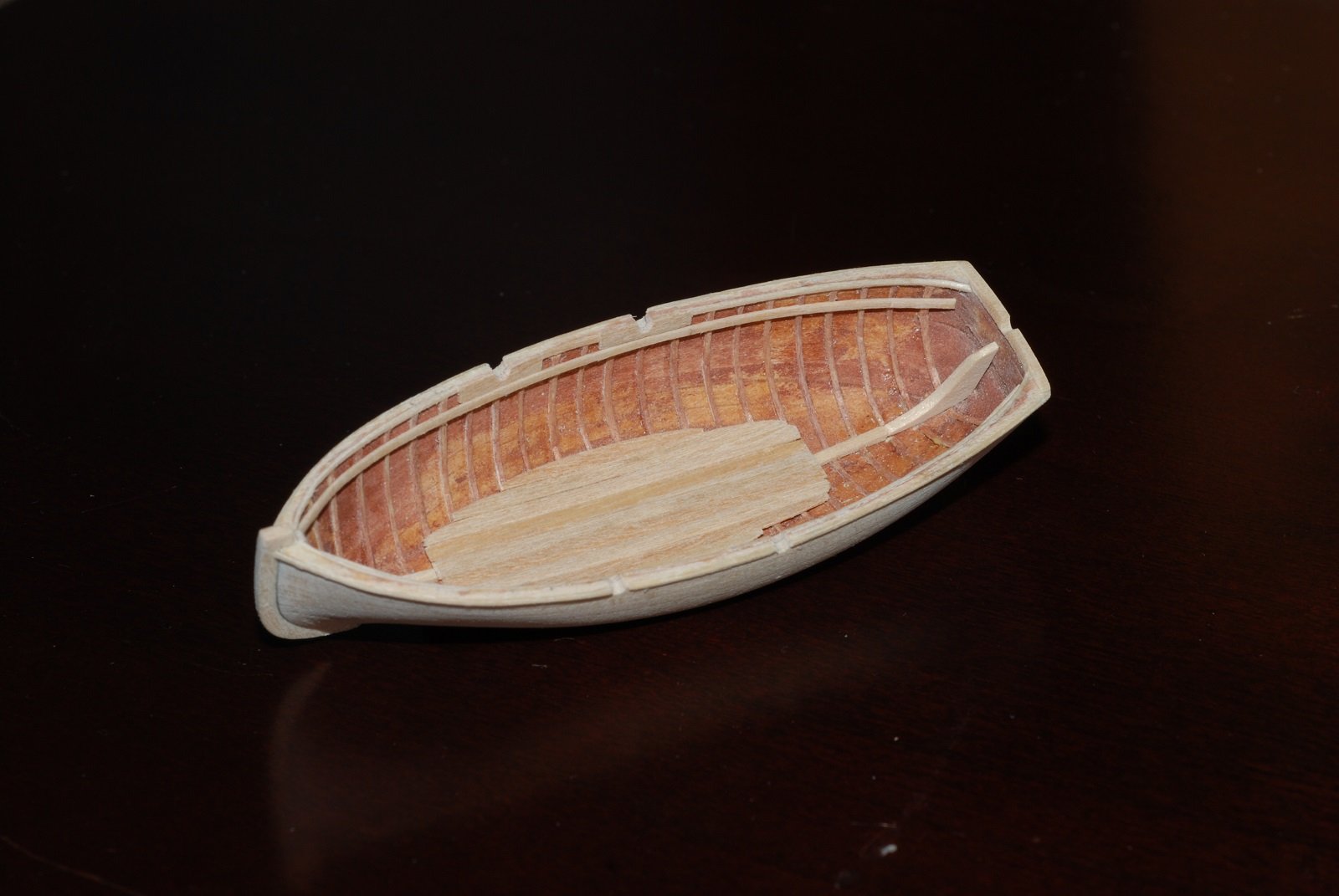
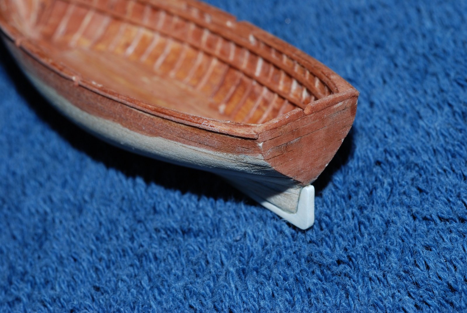
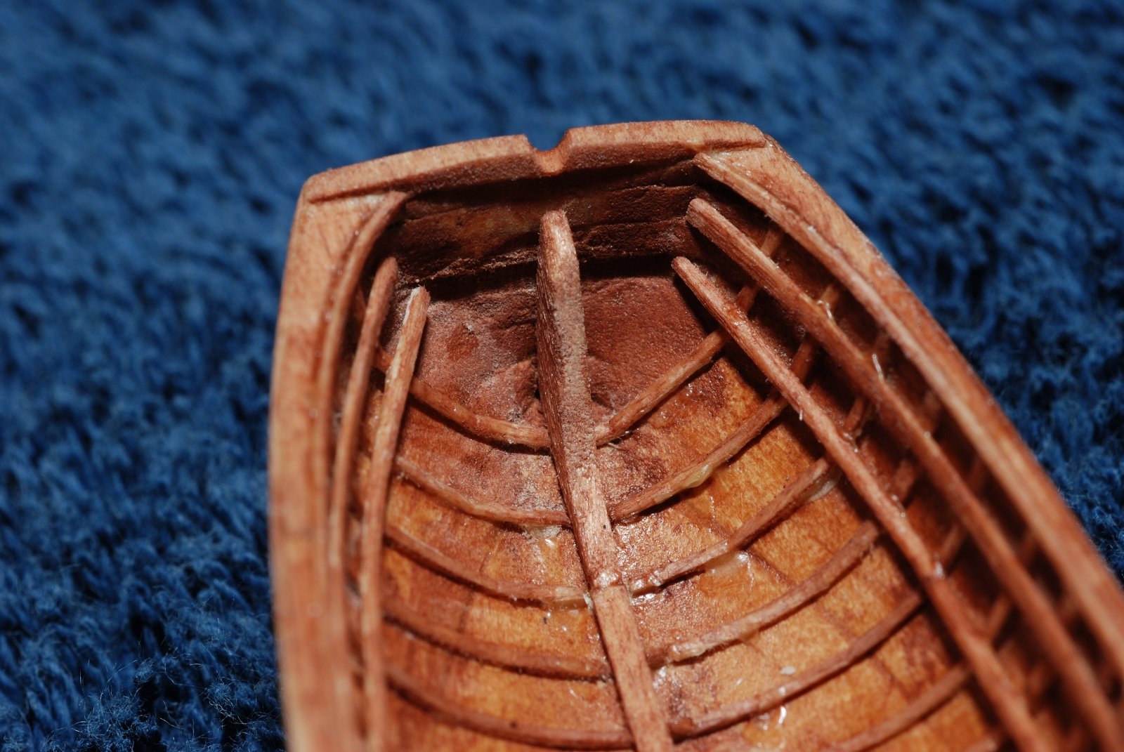
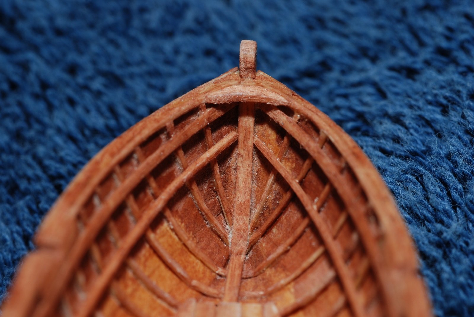
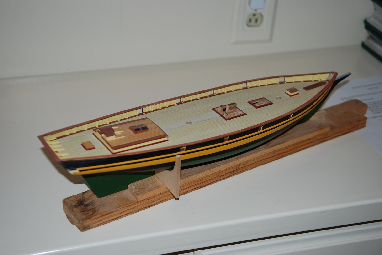
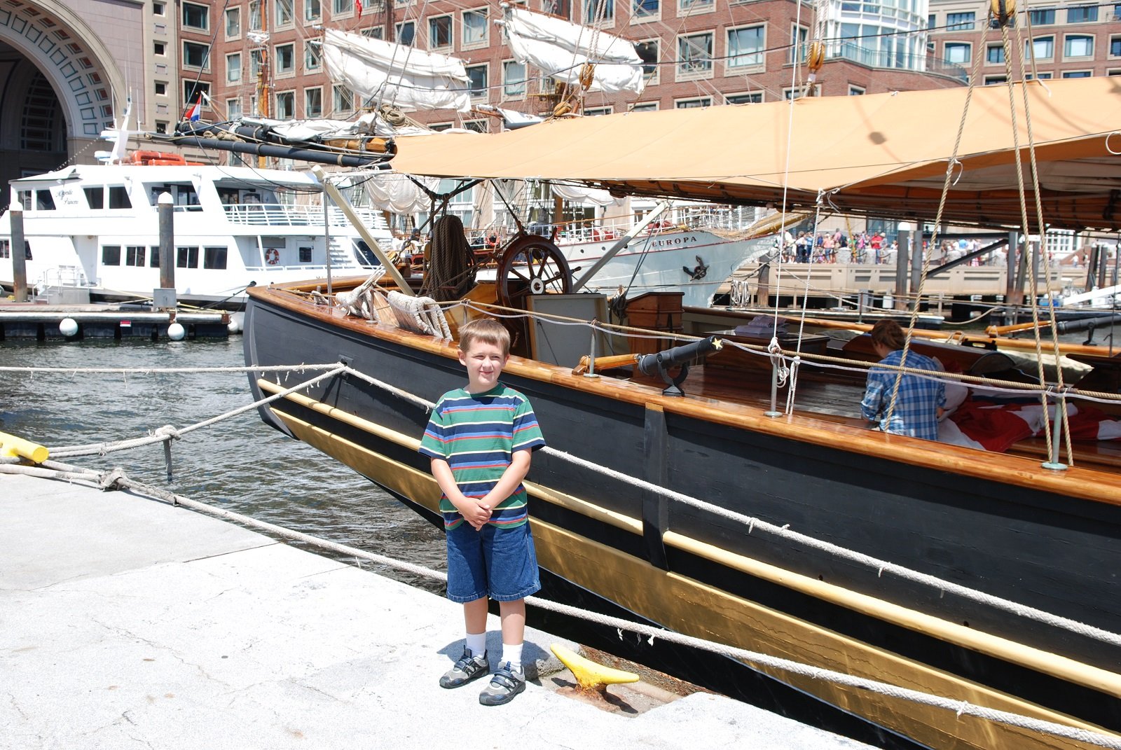
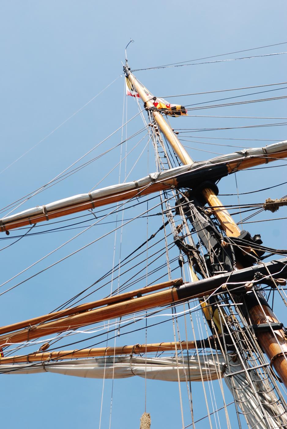
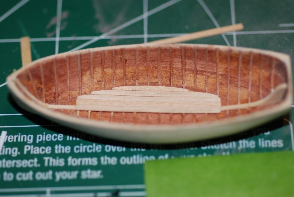
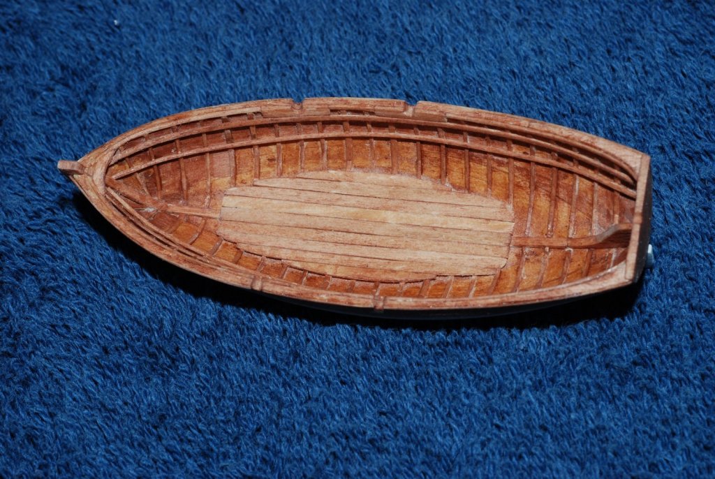
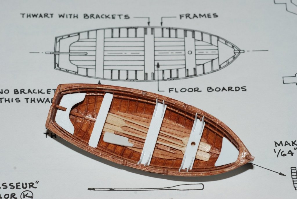
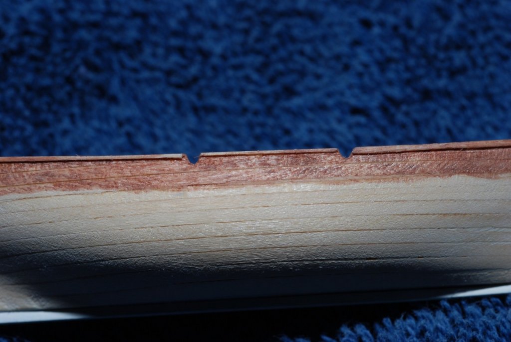
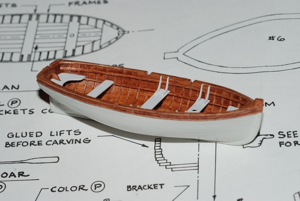
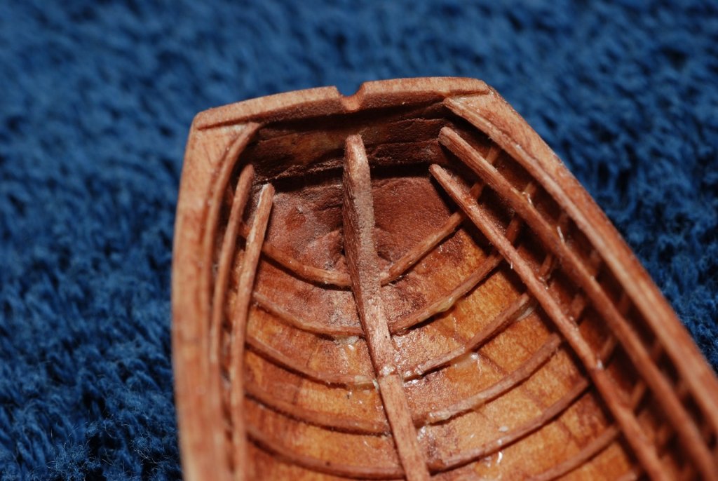
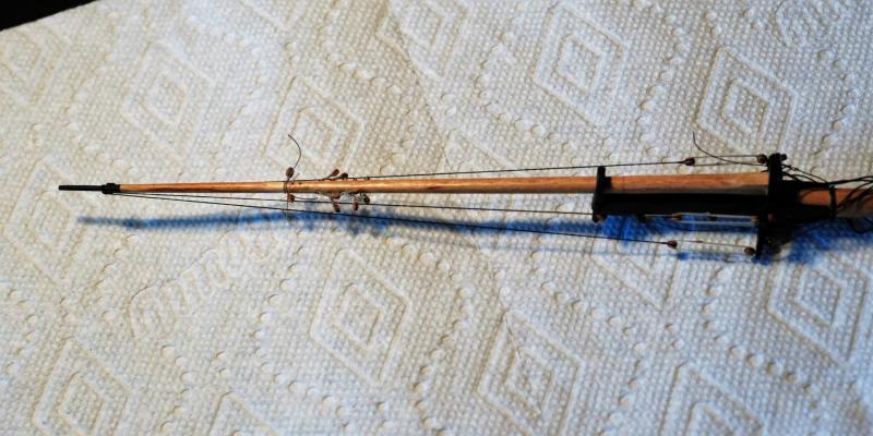
 Let’s talk about ship’s boats. In particular, Chasseur, the lapstrake planked ship’s boat on board the Pride of Baltimore 2. This is what she looks like in real life. Before I was ready to jump back into the pool of working on the big hull of Pride 2, I decided to re-examine what I thought I would do with the ship’s boat. When I started the model, I had been thinking that I would never be able to outfit such a small model boat (less than 2 inches long) with all the details she was worthy of, like a false keel, ribs, stringers, thwarts, etc., and so I pictured building the bread-and-butter hull out of the parts provided by the model, sanding it smooth, painting it, and covering it with a tied-down cloth cover so that no one would see that it was an unfinished interior. 2 things changed my mind. One was seeing the interior of the actual boat when we visited Pride 2 in July 2009, and seeing how beautiful all that detail was. The second was realizing that on the practicum I had bought for the Pride 2 from Lauck Street, there was a particular segment devoted to the building of ship’s boats, in particular ones fashioned from bread-and-butter technique (as opposed to building the hull up around a plug, a more accurate and cerebral technique). It made me realize that I was probably capable of adding more detail than I thought. I don’t have any pictures of the boat before this image, which shows that the false keel and ribs have been added, and part of the flooring is installed. Of course, what had to be done to get to this point was to use the drum sander attachment of my Dremel to grind off all the interior ridges of wood left behind by the bread-and-butter technique, then use sanding paper or files to reach all the nooks and crannies in the bow and stern of the model. I never reached the degree of sharpness in those areas that I desired, but at some point I decided to just move along. The interior surface was then stained. I did not put on a topcoat because I knew I had to glue the ribs in place, and any coatings would interfere with that. The ribs were an interesting step. At this time in my re-emerging modeling career, I did not think about using anything other than basswood. And I didn’t have any fancy table saws or thickness sanders. So the strips of wood were all hand-cut and hand-sanded down to a thickness that just seemed like it was right. They were probably between 1/32” and 1/64” in thickness and about 1/16” in width. They were super-pliable without running the risk of creasing them. Gluing them in place was purely a rack-of-eye kind of thing, making sure to install them vertically and perpendicular to the keel. The first ribs were placed in the midships, and all subsequent ribs were set parallel to those. The ribs were put in so that they bridged the boat completely from gunwale to gunwale, and then later the central portions were cut out to accommodate the false keel. This picture shows that the floorboards have been finished. The sheer has been cut to its proper profile, and two internal strakes have been added as well as a toprail. The oarlocks were very carefully cut out and reinforced with a thin veneer of wood surrounding each one. A lock for the tiller has also been cut into the stern rail. I think that if I had found my source of boxwood and pearwood by this time, I would have done these details with those woods. But I think things turned out well, and the grain of the basswood is not distracting. You can faintly see the layers of the bread-and-butter buildup technique in the transom. The interior is now all stained out. A breasthook has been added. You can tell on these images how tough it was to get into the corners of the bow and stern. But I was very pleased with the overall effect. The roughness shown in the images disappears at scale, and when viewed in close up I think it gives the interior a rustic, Wooden Boat School-type appearance. I think it was about this time that I purchased a macro lens for my camera (Nikon D80). That thing gets plenty of use!! Staining out the area of the gunwales and rubrails. A second rubrail would be applied. Again evident is the horizontal lines of the bread-and-butter buildup technique. Those hull lines disappear once the hull is fully primed and painted. The white paint on the hull was airbrushed on. The seats and thwarts are made from styrene sheets. Finally, I constructed 4 oars as well as a rudder and a tiller. The blades of the oars are admittedly oversized. I could not bring myself to hand-paint or otherwise apply the ship’s name to the transom. Call me a coward! Next time, back to the big boat.


- 60 replies
-
- 10
-

-
- pride of baltimore ii
- Model Shipways
- (and 1 more)
-
Thanks Tigersteve. The pace of posting may slow down some now. I have lots of pictures over many years, now it's a matter of putting the story to the pictures.
- 60 replies
-
- 1
-
-
- pride of baltimore ii
- Model Shipways
- (and 1 more)
-
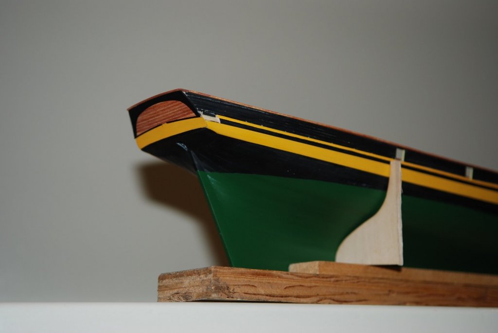
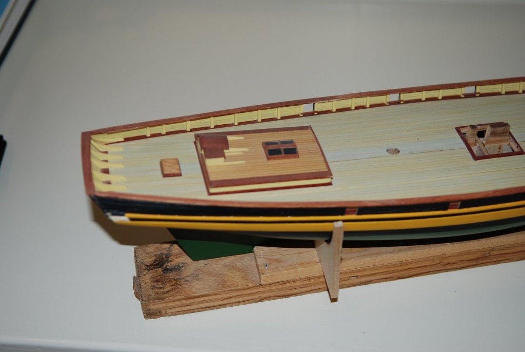
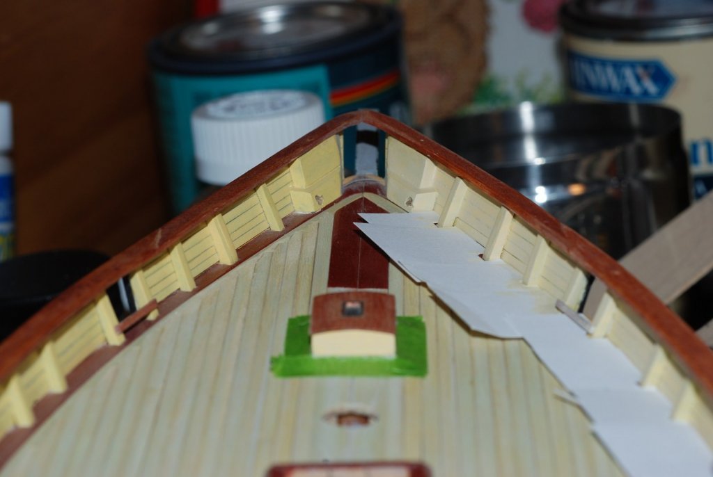
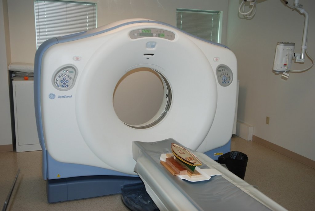
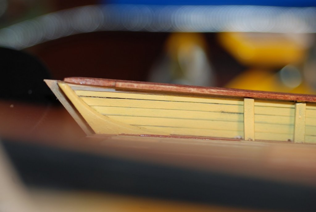
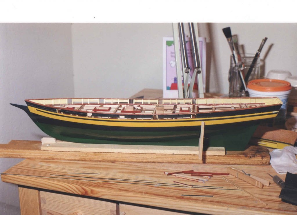
In 2008, when my older son was about 8 years old, the model finally came off the shelf. The hull and deck were fully planked, and it was for the most part completely painted. Coamings for the deck furniture were also in place and painted. The mast steps were also already in place. I think our story will start with the (mostly) assembled hull and proceed with bringing it up to date, installing deck furniture, creation of a base and ways, and finally getting to what I am now working on, the rigging. This first picture is how she looked after emerging from cryogenic storage. As mentioned, the deck has been planked up, and the bulwarks and rail are in place. I will always just have to accept that the curve of the rail is abnormally bumpy, and does not have a smooth flow to it. This is especially true in the area of the foremast pin rails. Other things worth noting about the model: the interior surfaces of the bulwark planking is painted a relatively bright yellow and not a cream color. This would be redone. Within the coaming for the midships cabintop, pieces of wood protrude that were used for clamping the hull in a vise back when it was being planked. These would of course be removed. I made the temporary cradle out of scrap and out of some of the wood sheet that defined one of the bulkheads. The fancy pieces of the transom have not yet been installed. This showed the strip planking of the transom, which would be removed and replaced with a sheet of basswood. The stern knees would also be removed since I had painted them, while in real life the stern knees are not painted. Back before the model went into hiding, I spent a lot of time building the aft cabintop, and was very proud of it. Even so, I know I could do a better job if I were building it today. I could have elected to rebuild it and make it more accurate given what I learned about the ship from photographing her in Boston in July 2009 (more below), but I felt that I would leave it as a testimony to my modeling skills as they were in the late 1990s. This is how things stood in the spring of 2008. I was very excited to be able to get back to work on the model. Our boys were old enough that we felt we were not constantly under water looking after them, and in addition, my wife had agreed to let me take over the guest room and set it up as my workshop! During this same time, I also found Bob Hunt’s Lauck Street Shipyard, and was happy to see that one of his courses had to do with building the Pride of Baltimore 2. I sent off for the practicum, and I still refer to it from time to time. Fast forward to April 2010. In that span of time, relevant things that happened including getting to see the actual Pride of Baltimore 2 in Boston. I thoroughly bored my wife and kids as I wandered all around the ship, taking pictures of anything I thought might be important. Captain Jan Miles was not there but the crew was very helpful. At this time, my older son was 9 years old (now 17!). During that time I also went to my first NRG convention, in Annapolis, MD. Being at the meeting and being around other people who were passionate about model ship building really galvanized my motivation to get working on the model more consistently. I also filled this time by building the ships boat. This was made a lot easier by going through the practicum about how to build ships boats. It was a nice, small project that enabled me to get back into the swing of things. I will cover that in a later post. Back to the big boat: this image shows that I have repainted the starboard bulwarks using a cream color that has far less yellow. Matching the color was greatly helped by having photos of the actual boat. There are pieces of cardstock that are protecting the planking while the repainting is done. I do remember being very happy how clean the repainting turned out. This is an inboard view of the port bulwarks where they meet the taffrail. I have stripped the planking from the taffrail and removed the stern knees. There is a strip of bulwarks planking under the stained rail that is unpainted; it was a shim that was put in to fill the gap created by the rail as it rises to meet the taffrail. This is an outboard view of the same area. I don’t know why it felt so intimidating, but that fancy piece caused me a lot of worry as to how I would go about creating that piece. Plus it had to be beveled on its inboard surface to accept the transom planking. Fortunately, the piece of wood used was quite thin, and it was easy to get it to bend to conform to the planking. While at the NRG meeting in Annapolis, I got the idea of putting my model through one of our CT scanners at work. This would lead to publication of an article about using CT scanning to study historical ship models, including 4 of the historic models in the Rogers collection at the USNA museum. Maybe that explains the big time gap in my photo documentation! But I digress… I think my next post will be about the ship's boat.


- 60 replies
-
- 11
-
-
- pride of baltimore ii
- Model Shipways
- (and 1 more)
-
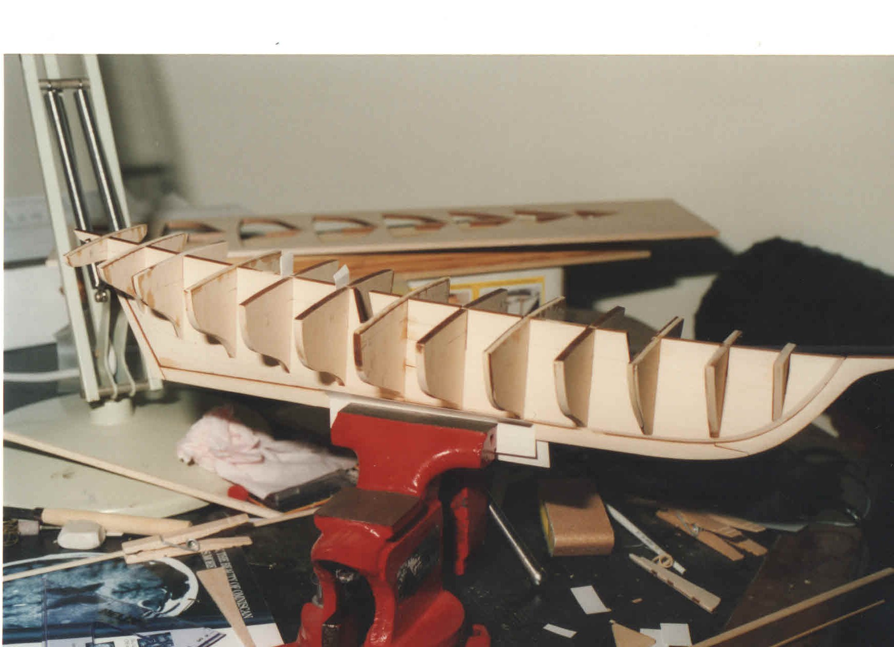
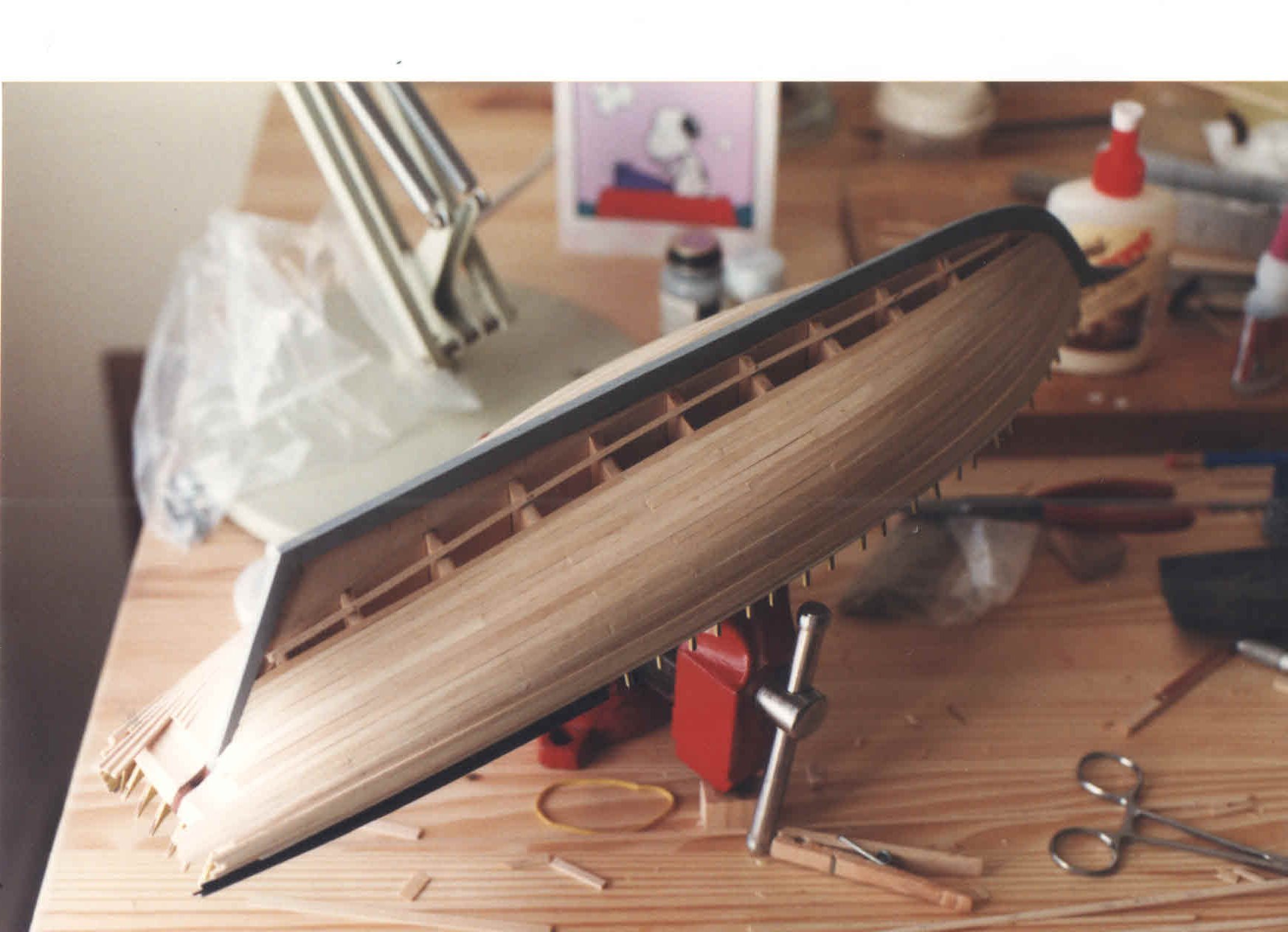
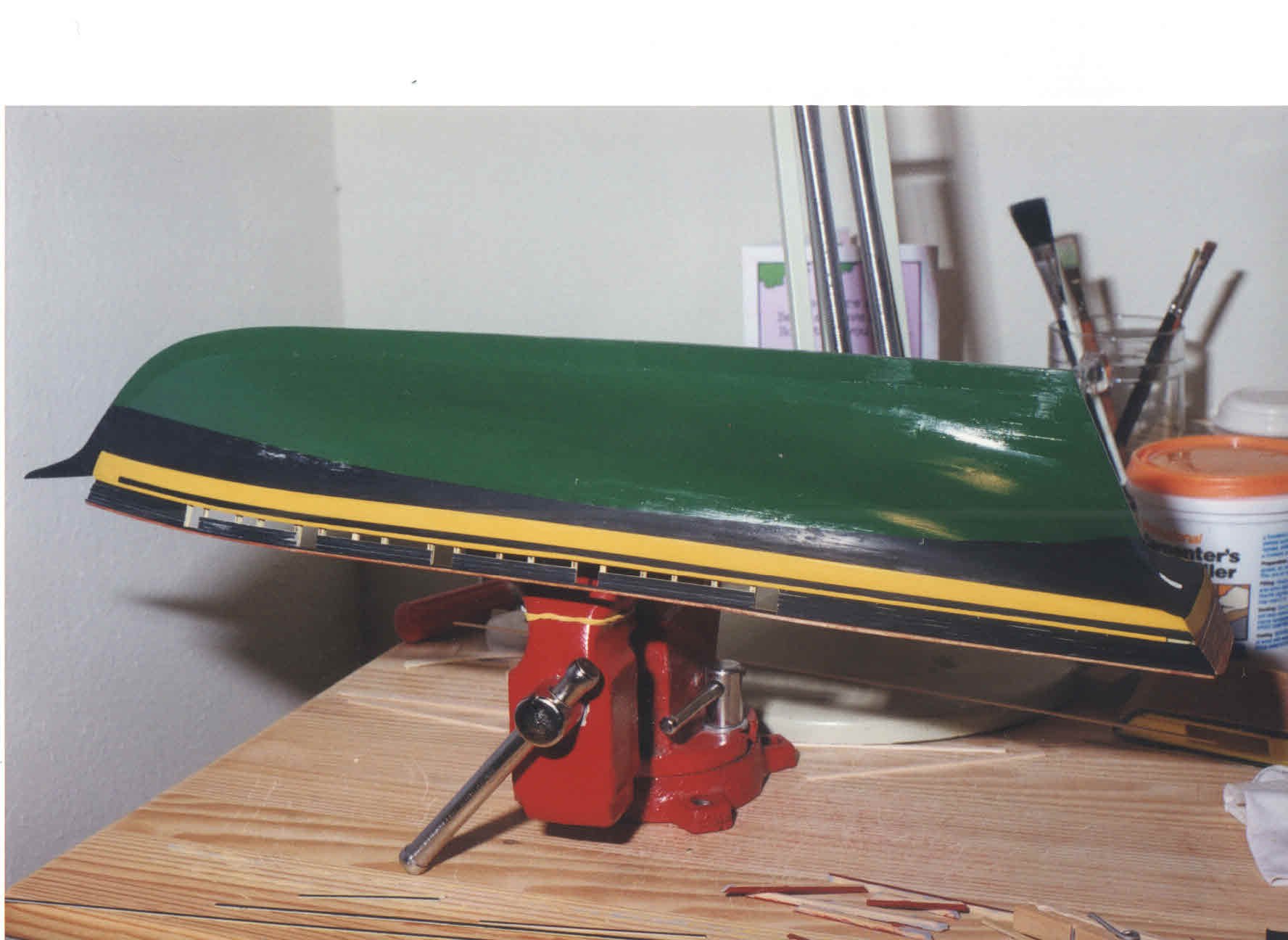
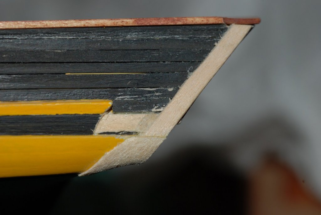
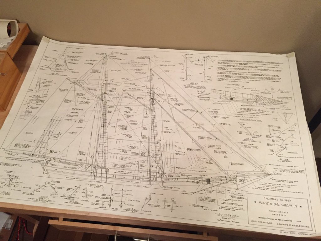
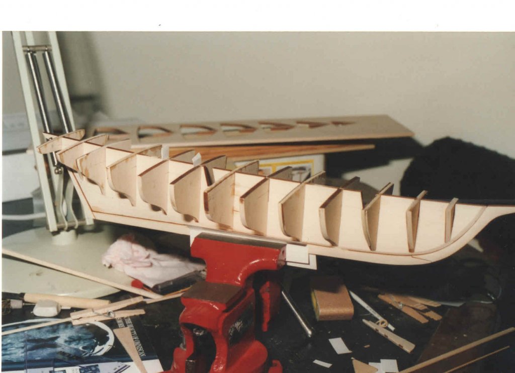
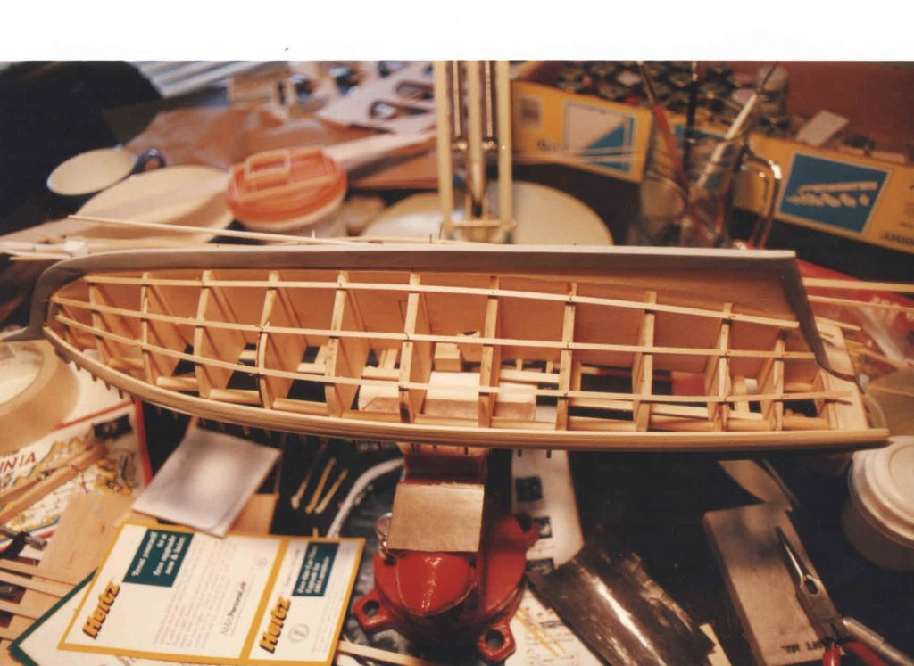
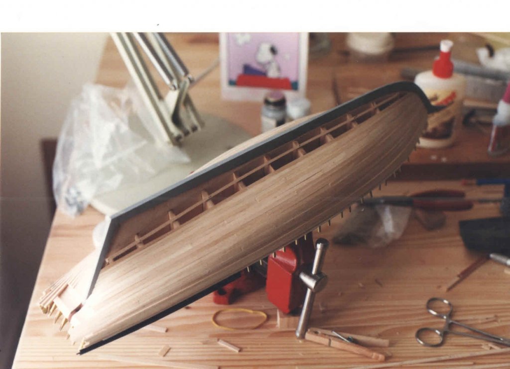
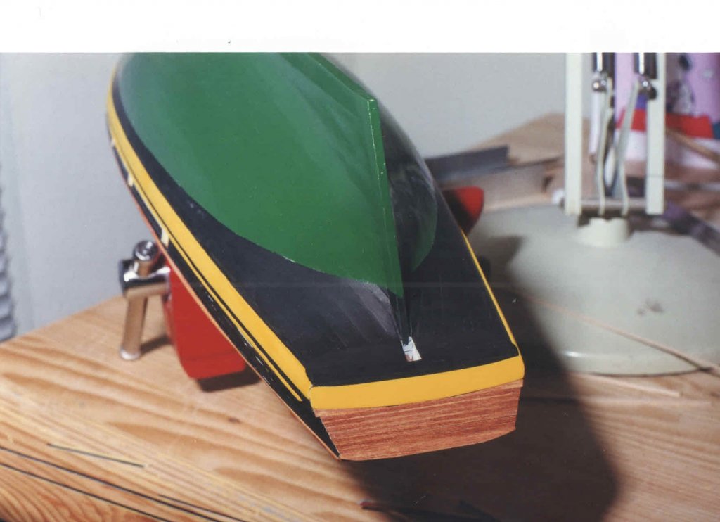
Ladies and gentlemen, there is no more postponing it. Time to start my building log. About 20 years late, but hey, better late than never. I am taking great pains to make sure I properly title this log, ccoyle, and I hope to do you proud. In 1995, when I was beginning my residency training, I invested about $130 in the Model Shipways kit for the Pride of Baltimore 2. I had built some simpler models and would complete at least one other before cracking open the Pride 2 box. But it was exciting to know that it was there waiting for me to wrap up my other projects. It would be the first serious fully rigged model I would build. Looking at the 6 sheets of plans really got the imagination going. Exciting, yes, but also terrifying for a young model builder to look at. The details are overwhelming. Just the bowsprit netting seemed to suggest that I would never be able to complete it! It is now 2017. My wife and I now have two boys who are 15 and 17 years old. Since 1995, the internet has come into existence and so has Model Ship World. So this building log will involve a lot of “retrospective” posts. At the current time, the foremast is installed and rigging of the foremast and bowsprit is proceeding. But I figured it is never too late to begin a builders log even if it is retrospective. I am doing pretty good photo documentation as of a couple of years ago; the documentation of the early phases of building the model is more scant. I actually started building the hull in 1997, and worked on it feverishly leading up to the arrival of our first son in 2000. Once he arrived, the hull got put away, relegated to the top shelf of a closet. There was just no time. But fortunately, I did think to take some pictures of the hull as it was being built. I recently uncovered these prints, and had to scan them into the computer in order to be able to attach them. How far we have come… These pictures date from about 1998-1999, when we were still living in an apartment during my training. In retrospect, I am amazed by how intuitive the planking process was. About 8 years later, when I went to my first model building symposium, I listened to a talk about planking technique and remember thinking, “Hey, that’s the way I did it!”. I wish I could remember how many weeks it took me to plank the hull. But I wasn’t keeping track of the time I spent on the model. I don’t remember what source I used to learn about nibbing planks and stealer planks. I think they were described in the kit’s instruction manual. This wasn’t my first planked hull, but it was the first time I applied those techniques. There is a gap in photo documentation between finishing the planking and painting the hull. The bulwarks planking and rail also get added during that time. The transom was also planked, but that would get pulled off later in favor of a sheet of basswood with the ship's name engraved in it. I built a cradle out of scrap wood to stabilize the hull for the process of planking the deck. I have no picture documentation of that process, but it proceeded very logically, even more easily than the hull planking. The coamings for the cabintops and hatches were installed prior to planking. Better hurry, that baby’s coming! No more modeling for a while after he gets here… But before it got put away, I was fortunately able to install the foc’s’le hatch and the aft cabintop. I also installed the deck hatch aft of the cabintop. The last of the attached images is how things looked once the model got placed in cryogenic storage on the top shelf of the closet in the house we moved into when I finished training. Hey, I got a lot done, in retrospect! Next post: the model gets resurrected after a long hibernation...
.jpg.04d82f9c7ebd45ff80505314095691e1.jpg)

- 60 replies
-
- 15
-
-
- pride of baltimore ii
- Model Shipways
- (and 1 more)
-
I am in the thick of rigging my Pride 2 model, and I like not having the mast glued in. I have already had to "de-rig" the foremast one time, and it's comforting to know that I can do that if I realize I forgot to do something to the mast that is easier off the boat.
-
I have been very happy with Flexament cement for securing fly tying line. It's like a diluted rubber cement.
-
I agree with Mike Y that a height adjustable table (sit-stand table) is indispensable. In my work, we have motorized height adjustable at all our workstations for ergonomic reasons. The ones we use are expensive, on the order of a couple of thousand dollars. I invested in one for my shop; I'll send a picture later. I'm glad to see that Ikea is offering a cheaper alternative; I'm surprised that there aren't more options out there.
-
Looking for a good first "plank on bulkhead" kit.
jdbondy replied to DonInAZ's topic in Wood ship model kits
My first plank on bulkhead kit was Bluejacket's America, the smaller one at 1/8" scale. On their web page it is shown as planked on only one side. I planked both sides fully, then painted it. I did not try to follow any strict rules of planking. I just used the kit to get a sense of how the process of planking worked. -
Mikiek, I know exactly what you mean. I have some Unithread 3/0 and I cannot use it because it unravels into many tiny threads. But it's not much smaller than any of the natural fiber threads I am using, so I don't have much of a use for it anyway. If you got some Unithread 6/0, you shouldn't have the same problem. It does not fall apart into smaller threads. You will find that the 6/0 is not round; it is more flat in cross section. Seizings made with it will be slightly irregular in surface contour because of this, but you would have to be looking close. What I like even better is the Veevus 16/0, an incredibly tiny thread that is still slightly flat in cross section but so small that it doesn't matter. I am building in 3/16" scale, and the seizings made with the Veevus are incredibly fine and smooth. I am still working out when to make a seizing with 6/0 versus when to use the 16/0.
-
So now I have to go back and mouse all my hooks!!
-
Help! Need to redo topmast shrouds...
jdbondy replied to jdbondy's topic in Masting, rigging and sails
Thanks, Druxey. The end loop of my long strops are each closed, since I had first fastened them to eyebolts. So I can't tie them to the shroud with a clove hitch, but I am working around it. Essentially, I am tying a very small knot with my finest thread to the shroud, to serve as a "shelf". After that has been secured with glue, I am tying the blocks with their long strops to the shroud just above that shelf knot and gluing that, so as to keep it from sliding down the shroud. -
I have been working on building the POB II for the past, oh, 16 years. Raising kids has gotten in the way. I currently don't have a build log, but I recently started documenting what I am doing so I can better re-create a blog when I get around to it. I think it's a great ship! and super convenient that it is contemporary, so you can actually take photos of how it currently looks and use that information. I'm not one for doing lots of research into how something may have looked in the past. I'll be following along!
- 164 replies
-
- 2
-
-
- Model Shipways
- Finished
- (and 1 more)
-
Help! Need to redo topmast shrouds...
jdbondy replied to jdbondy's topic in Masting, rigging and sails
Gunther, glad to see that you did essentially what I am doing. -
Help! Need to redo topmast shrouds...
jdbondy replied to jdbondy's topic in Masting, rigging and sails
Oh, and now I have to migrate those 5 pairs of blocks from the topmast to the shroud, to which they should be seized. If anyone has any suggestions on how to securely tie the blocks to the shroud without allowing them to slide, I am all ears. The blocks have strops (probably not the right term to use) of varying length, that increase as you go toward the top. The stropping line forms an eye that I am currently using to tie the block to the shroud. -
Help! Need to redo topmast shrouds...
jdbondy replied to jdbondy's topic in Masting, rigging and sails
Repair of the topmast shrouds is complete. I was able to move the top of the shrouds down to the lower level, and take up the slack at the deadeyes. I redid the lanyards securing the deadeyes to more accurately reflect how they are on the actual vessel. They are wrapped twice around the shroud where it is seized to the deadeye, then brought back down to one of the lanyard strands between the deadeyes and seized to it. Some of the deadeye spacing is still pretty wide. I had to live with that when I ended up cutting the shrouds a little prematurely. But overall the result is an improvement. Making good use of that Flexament fly tying cement for securing the synthetic thread to the Morope. No, I don't own stock in the company...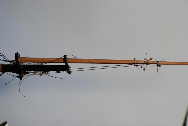
-
Mikiek, regarding your question on the size of fly tying line, 3/0 is larger than 6/0, which is larger than 8/0, and so on. I am currently using a lot of fly tying line ranging from 6/0 (which is about 0.003") to the smallest I can find which is 16/0 (about 0.001", so like a human hair). Despite the small size, these synthetic lines are surprisingly strong. I am really enjoying seizing blocks to eyebolts using these synthetic fly tying threads. There is no fuzz; everything looks very neat. In a separate post, I have brought up the topic of Flexament cement, which is sold by fly tying kinds of places for bonding synthetic thread to natural fibers. It is working well for me so far. Look for Uni-Thread or Veevus. Veevus makes the really small stuff.
-
Les, I've been in touch with the makers of Flexament, and they describe it as intended for bonding synthetic and natural fibers, with the ability to hold up in adverse conditions such as wetness and sunlight. 10-15 seconds for it to start working, and set in 1 hour. I made a seizing using Unithread around some Morope, applied Flexament, and let it sit overnight. I cannot get the Morope to budge within the seizing without applying a really high amount of tension, far more than we would put on a model's rigging. For now I think my plan is to use varnish/topcoat on seizings or knots that are entirely natural fiber, and Flexament on seizings or knots that are a mix of natural and synthetic fiber. I am trying not to use CA at all, except for curing the tips of rigging line for threading purposes.
-
Ulises, my point about cleanup was that I was typically applying the varnish with a brush, which I then have to clean up with spirits. So I was tending to keep that to the end. However, your comments have made me rethink the application process. I've started applying varnish like I do CA, with a pair of tweezers dipped in the varnish. Now, cleanup consists of wiping the tip of the tweezers with my fingers! Much easier. Now I have 3 separate tweezers, one for CA, one for varnish, and one for Flexament. Each is appropriately labeled.
-
The problems I am encountering using varnish as an adhesive are: 1. I'm not sure how secure of a bond is created between a synthetic fly tying thread and a cotton/linen rigging line with varnish. 2. Since varnish has to dry overnight, I have to leave my knot gluing until the end of the work day, so I just have one cleanup after gluing multiple knots. As a result, I lose track of which knots I have tied and need to be glued up. It would be nicer to have something that can be applied when the knot is tied, bonds pretty quickly, and doesn't require cleanup. I'll see what info I can find out from the manufacturer.
-
Help! Need to redo topmast shrouds...
jdbondy replied to jdbondy's topic in Masting, rigging and sails
Progress has been made. As I mentioned earlier, I was able to wiggle the seizings at the top of each shroud loose, without using acetone or other chemicals. I think that's because I had used flat topcoat on them rather than CA. I then cut them free. Since then, I have cut two of the shrouds where they were attached to the deadeyes, and brought the slack portions of the shrouds around the deadeyes. I have re-seized the 2 shrouds to the deadeyes using 6/0 Unithread, and I am trying Flexament cement (as I have mentioned in a separate post). The process of re-seizing the shrouds to the deadeyes has gone pretty smoothly; I put a prelim seizing on the shroud, scooting it up the shroud away from the deadeye, and then apply the proper amount of tension to the shroud and lanyards. Then I tie the final seizing so it is right up against the deadeye. At this point I am not adjusting the length of the lanyards between deadeyes, so that it remains fixed while I repair the shrouds. I'll try to send more pictures later today. -
Has anyone tried using a fly tying adhesive called Flexament? I am trying it on seizings that are done with synthetic fly tying thread. Since I am trying to swear off of the CA for fixing seizings, I have tried dilute white glue (doesn't bond well to synthetic thread) and flat topcoat/varnish (requires setting overnight). Flexament appears to be a possible solution. It appears to be thinned rubber cement, or at least it certainly smells that way! So far, testing a seizing made with 6/0 Unithread appears to be giving a pretty fast and durable bond.
-
Help! Need to redo topmast shrouds...
jdbondy replied to jdbondy's topic in Masting, rigging and sails
Will take a look at that deadeye spacing, druxey. Although the perspective is skewed, I have attached a pic of the rigging I took a few years ago. See what you think.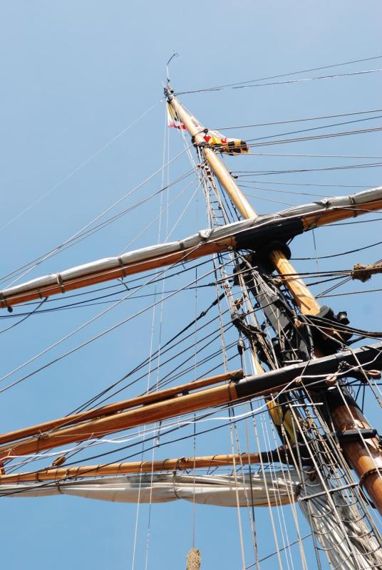
-
Help! Need to redo topmast shrouds...
jdbondy replied to jdbondy's topic in Masting, rigging and sails
Thanks Gunther. Without having to apply any acetone, I was able to loosen the seizings at the top of the shrouds and then cut them free. I have re-seized each of the shrouds at the correct level on the topmast, which of course leaves tons of slack at the level of each deadeye. Now those seizings I cannot free up. I think I did them differently than the seizings at the top of the topmast. So, I have cut one of them loose and plan on re-fastening it to the deadeye. One nice thing is that the deadeye lanyards remain intact, so getting the tension right should be pretty easy. I'll post some pictures when I get them moved to this computer. All in all, less work than I anticipated (thus far)... -
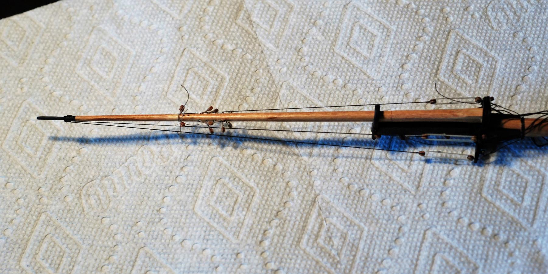
Help! I just realized that when I painstakingly installed the topmast shrouds, I took them way too far up the topmast. They need to end at the level of the uppermost pair of blocks that are installed on the topmast. (Picture is attached.) The shrouds are each seized to the topmast, and of course they each terminate at a deadeye at the crosstrees. I am afraid that when these were installed, I applied CA glue to the seizings (I have since stopped using CA on seizings). I am ok if we think I just need to cut them and start over, but before doing that, I wanted to see if anyone has any other ideas. If they were not glued with CA, I could just shorten each shroud at the deadeyes. But I haven't tried moving anything yet to see what happens. Once I'm done with that, I'll need to move those 5 pair of blocks off the topmast and seize them to the shrouds, like the plans said I should have done in the first place...
-
Turning brass thimbles
jdbondy replied to jdbondy's topic in Metal Work, Soldering and Metal Fittings
Hi Wefalck, The lathe is a Sherline 4400. I am using a collet on the tailstock of course; I guess you are suggesting another collet for the headstock. I used a file to cut the groove because I was just too lazy to go back to the bench grinder and create another cutting tool for making the groove! The file worked fine but I agree that another cutting tool with a pointed tip would be more optimal and reproducible. I received the K&S tube cutter recently but I can't get it to work on the relatively small size of the brass tubing I have (1/16"). I'll put it away for when I have larger tube that needs cutting. JD