HOLIDAY DONATION DRIVE - SUPPORT MSW - DO YOUR PART TO KEEP THIS GREAT FORUM GOING! (Only 13 donations so far - C'mon guys!)
×


jdbondy
-
Posts
340 -
Joined
-
Last visited
Content Type
Profiles
Forums
Gallery
Events
Everything posted by jdbondy
-

Warped frames
jdbondy replied to jdbondy's topic in Building, Framing, Planking and plating a ships hull and deck
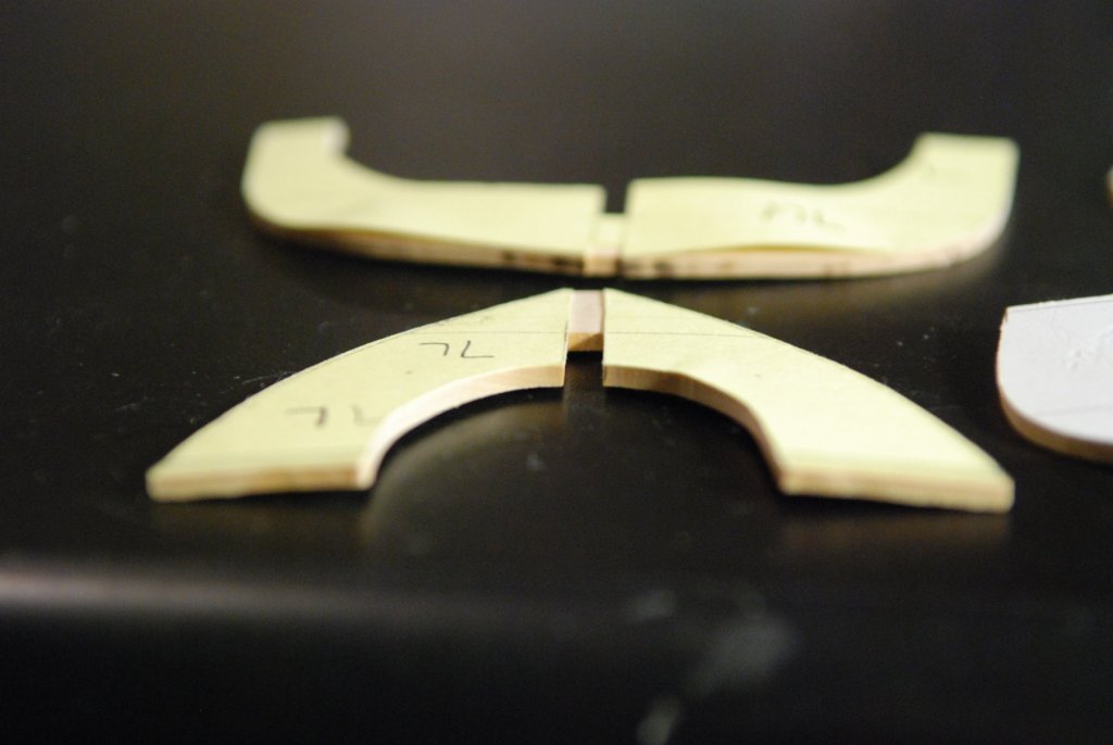
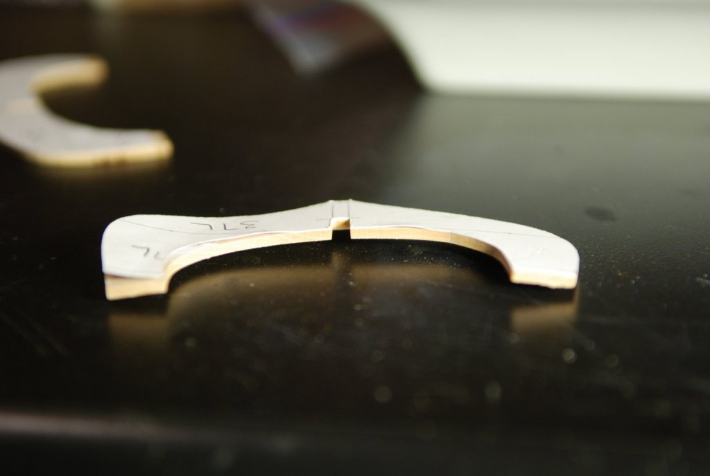
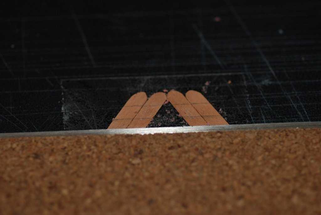
Thanks for all the feedback. I am in north Texas, and the humidity does fluctuate between 30% and 100% with passing weather fronts. So that doesn't help. Since the original post, I took two layers of 1/8" castello boxwood and glued them to each other with wood glue. This was left overnight. I then cut out two frame shapes that approximate my warped frames shown above, then used the thickness sander to bring the shapes to about 3/32" thickness. This was done symmetrically, so the glue joint is in the center of the thickness of each shape. Within hours, these frame shapes had developed significant twist. So laminating two layers is not a solution either, it seems. I was hoping to build my model in plank-on-frame style, but I am afraid that this means that I will revert to a plank-on-bulkhead method and use basswood for the interior structure, saving the boxwood for planking. It's a little disappointing, because I have builders plans for the model and wanted to take full advantage of that. But Mark P, I think you are right that it was a pipe dream to hope that cutting frames from a sheet would yield flat frames. Nirvana, the patterns were applied with rubber cement. I thought that the patterns could have had an effect but I don't think that removing the patterns would have prevented the warpage. -
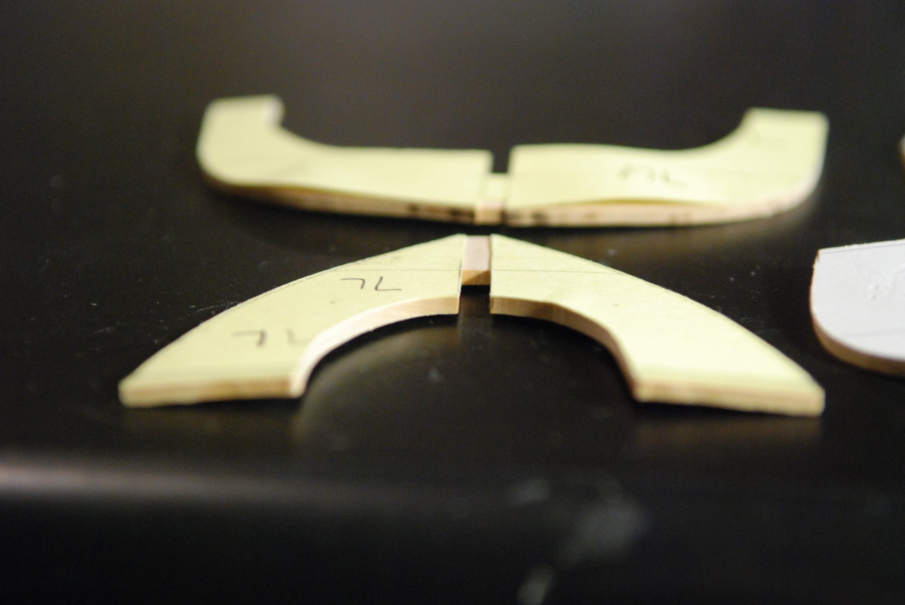
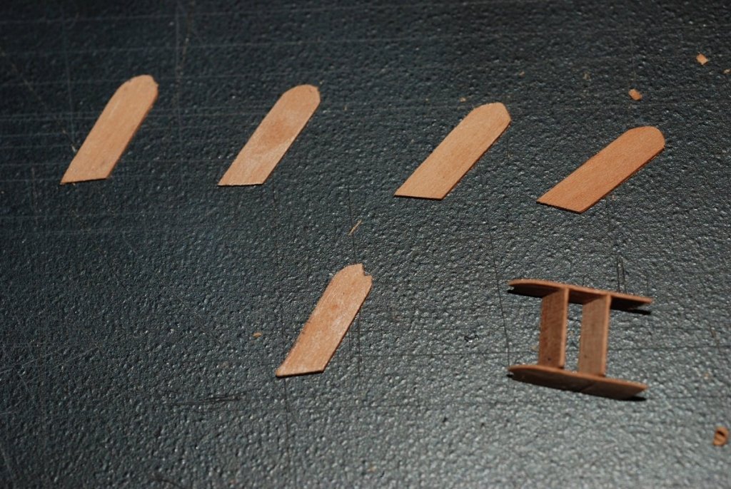
After visiting a modeler friend recently, I returned to my current project with excitement, only to find that some frames that I had cut out from boxwood sheets several months earlier now show severe warping: The grain of the wood is of course oriented vertically on these frames. Other frames were cut out with the grain running horizontally, and as you might expect, they warped in a manner perpendicular to these. These frame shapes were cut from a 1/8" boxwood sheet, and they were sanded to a thickness of 3/32". The model is going to be of an 83 foot schooner done at 3/16" scale. The 3/32" thickness of the pieces shown above corresponds to the thickness of the frames on the builder's plans. So it appears that in order to avoid warping, I will have to laminate 2 layers of 1/8" boxwood together, then rough out the frame shape, then thickness sand the shape equally on each side so that I have fibers of wood running in perpendicular directions surrounding a central core of glue. But I am worried about how much wasted wood that will involve. Plus, when the frames are brought to their proper molded dimensions (on the order of 3/32-5/32"), I am worried that they will still warp because of their very fine dimensions. I really don't want to have to mimic how the frames were built in reality because that would be so much more work. Let me know of any ideas you have! I was hoping that the boxwood would be better behaved than this.
-
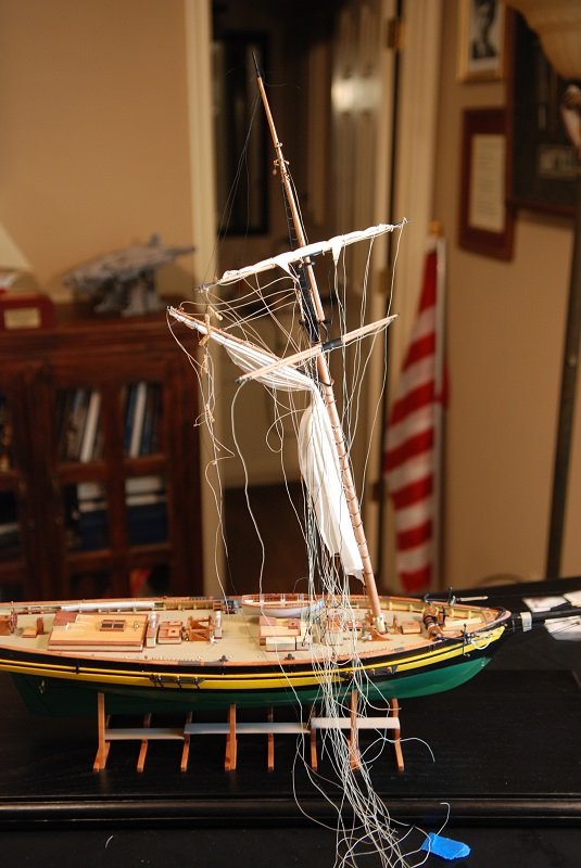
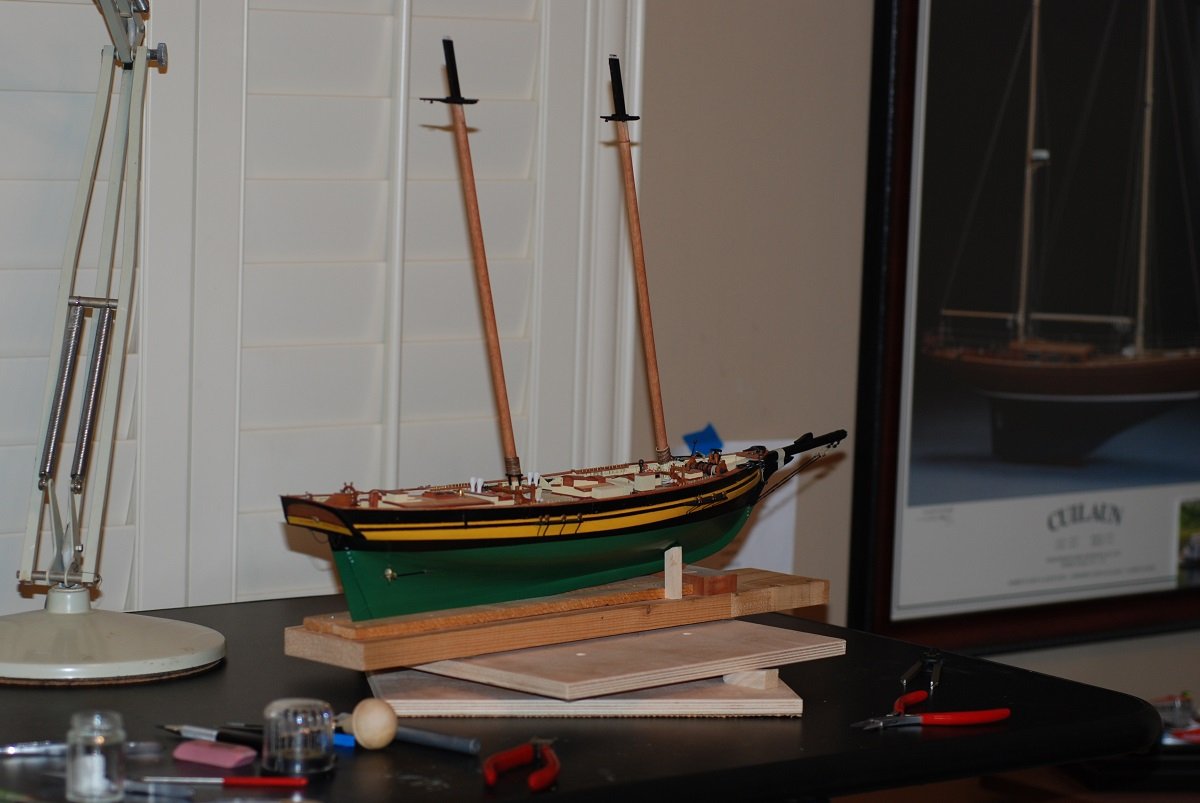
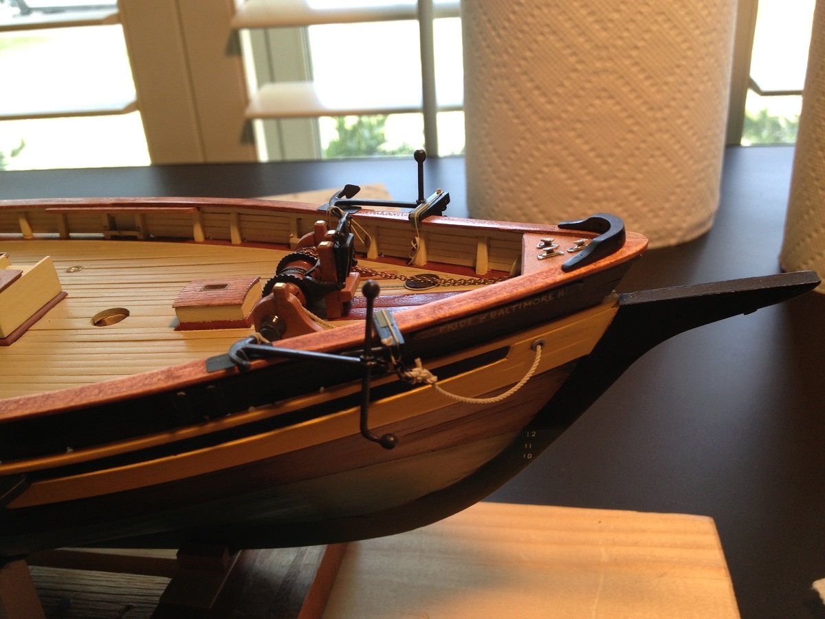
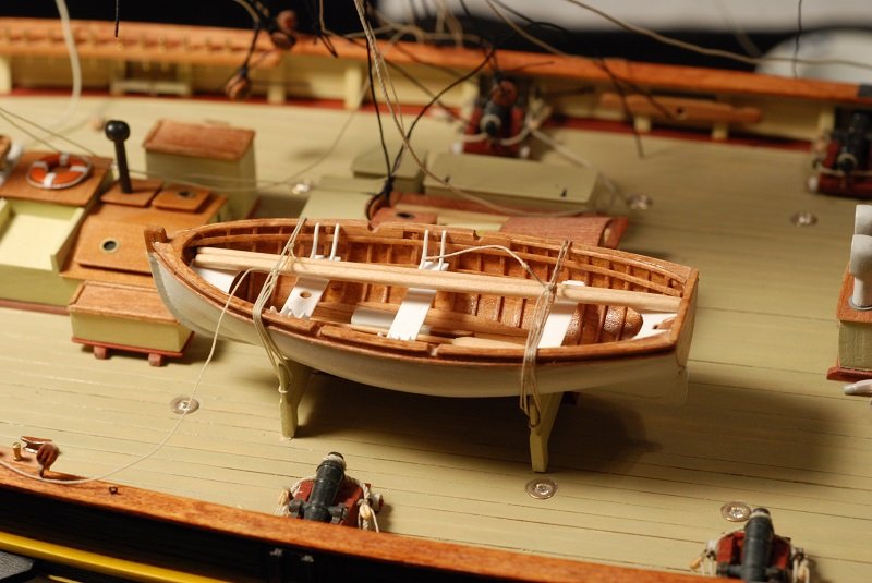
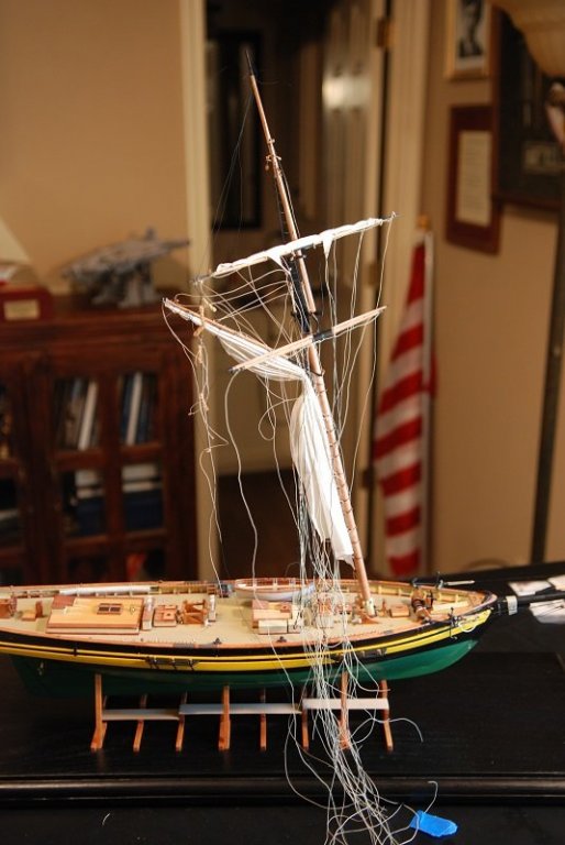
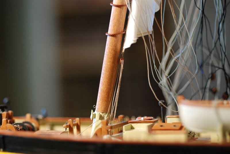
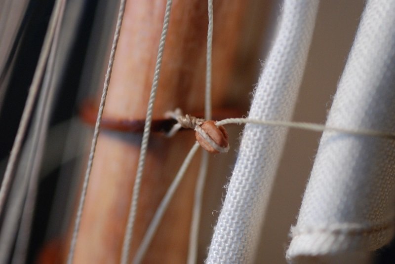
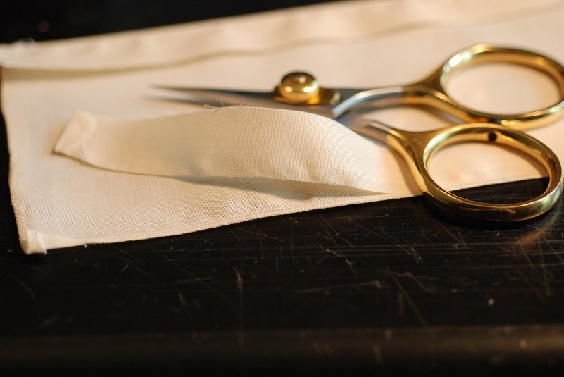
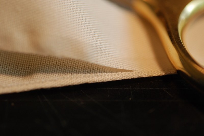
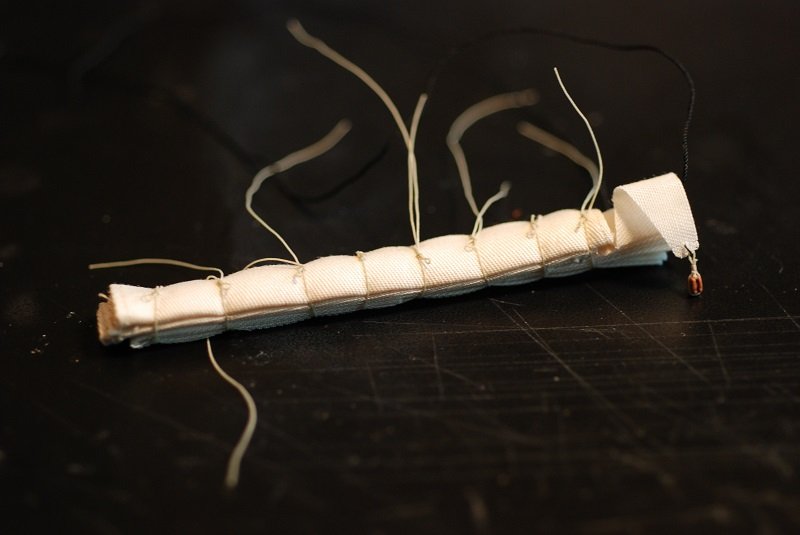
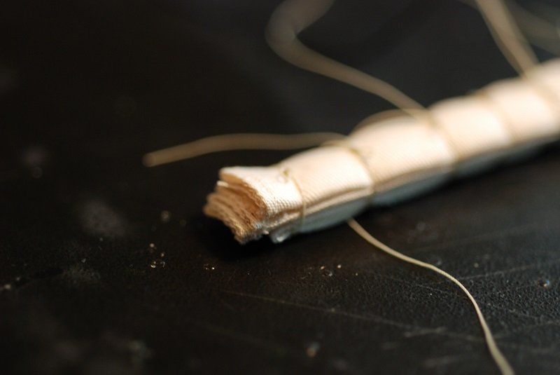
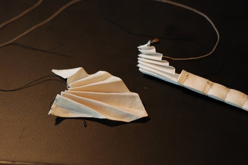
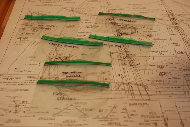
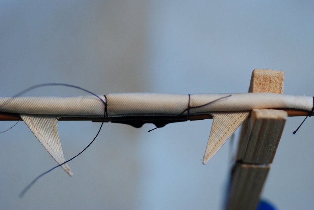
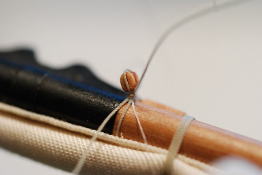
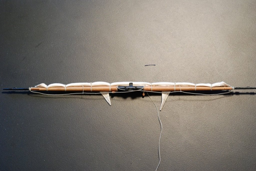
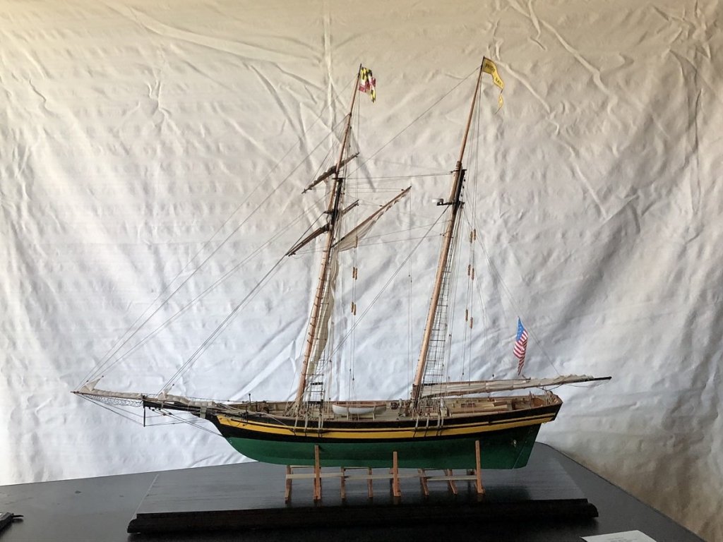
So at this point it is the fall of 2016 and we are within 2 years (!) of finishing the model. What remains is installation of the masts and associated sails and spars, then sorting out the rigging. Which, I might add, is my favorite part of building ship models. I love sorting out all the lines and bringing everything to manageable order, just like the sailors who actually sail these ships have to do in reality. But first, I went ahead and installed the ships boat, Chasseur, which was finished many years ago as I began to ramp back up my ship modeling efforts. I did have to take out all the spars and oars, and give it a good dusting. Two lines secure the boat to its cradle; I did not have much to go on in terms of how this line was rigged, but I think in the end that it looks reasonable. These are the brail blocks that are installed on several of the mast hoops for the foremast. The model will display a furled foresail, pulled up against the gaff and the foremast. These very small blocks (3 mm blocks as I recall, a little smaller than a 3/32” block) had to be carefully rigged so their seizing wouldn’t come apart under tension. Here I am bending the foresail to the fore gaff. The fore gaff remains in its rigged position when the boat is docked; it does not come down. The shape of the sail had to be cut so that when I furled it up against the gaff, it would flake neatly against it without too much bulk. The same was true for the part of the sail that would be furled against the foremast. A running stitch was used to rig the sail to the gaff. Before bending the sail to the gaff, I picked the points where the line would travel through the sail and marked them with pencil points. I then opened them with a needle, then applied some of the anti-fray material to the area so that the holes would hold their shape. Black thread was temporarily used to tack the furled sail up against the gaff and the foremast. These will be removed later, once all the brailing lines are in place. Also evident on this image are the attachment points between the leech of the foresail and the mast hoops. I just had to see how it would look with the mast put into the hull! The yards have not been attached yet, and no work has been done yet on the headsails rigged to the bowsprit. More on that in a second… Now, the yards have been attached, which really turns things into a bird’s nest of lines. All of the control lines for raising and lowering the yards as well as the associated topsail will have to be run through the control blocks on the topmast, which hasn’t been done yet. The lower yard is secured to the mast with chain in addition to its control lines. I used some fine chain that was coated with heat shrink tubing for that bit. The line controlling the tack of the foresail is shown here. I am pretty sure I included this picture after I had to re-install some of the brailing blocks when their seizings didn’t hold under tension. And now, a diversion. Before proceeding further with the foremast installation, the jib and fore staysail have to be rigged to the bowsprit and the forestays themselves have to be installed. Then we can start attaching lines to their belaying points, starting as centrally as possible and proceeding in an outward manner. That means the lines attaching to the foot of the mast go first, then the lines attached to the pin rails before and behind the mast, and finally the lines that belay at the pin rails at the periphery of the deck. So here we go: These are images from the manufacture of a rectangular piece of belvedere cotton cloth that was used as a skin to wrap the furled fore staysail. I sewed a very narrow hem on the edges of the cloth using fly-tying line for thread, then used fly tying scissors to cut the excess cloth off as close as I could to the hem. This was pleated and placed on top of the fore staysail. I had already made and flaked the fore staysail some time earlier, and it was unhemmed. I decided to leave it as is. The halyard block is therefore somewhat precariously installed in an unhemmed corner of the sail. Furling lines have been put on, tied off with furling knots. For the jib, I hemmed a scrap of cloth that was then furled up with another rectangular piece of cloth. Thanks to the hemmed edge of the jib, the halyard block for the jib is therefore much more securely attached to its sail than for the fore staysail. In addition to the fore staysail and the jib, there should also be a jib topsail rigged to the most forward of the stays. But the bowsprit would have become excessively crowded if I had tried to install 3 headsails. Each of the two headsails had to be threaded onto their various stays and loosely secured until the point that the stays could be put under tension. Tensioning the forestays of course involves lots of work with the deadeyes at the bow of the hull. Some of that rigging is shown here. In particular, the thimble beneath the bowsprit secures the fore topgallant stay, which is the foremost and tallest of the fore stays. Creation of the thimble was a very satisfying task using my lathe; I had never tried to use it for the manufacture of something so small. So just a brief aside: the thimbles were turned from 1/8” brass rod. The center was first bored out, then the outer diameter was turned. A notch or groove was then turned in the thimble, and it was parted off. I made about five of them for use at various places in the model. Three of the thimbles, after turning but before finishing with sandpaper. They were then put in blackening solution. Very satisfying! Multiple bits of the rigging also had to be created and tracked. I put them into their own Ziploc bags to keep track of what was what. The jib topsail halyard, fore staysail sheets, and mainstay runners are shown here as well as the fore topgallant stay. Not well documented in my photographs was putting the forestays under appropriate tension. But once this was done, I started to tie off lines associated with the foremast. These lines included the sheets and clew lines for the topsail rigged to the square yards, as well as the topgallant halyard. The tack line for the foresail also was tied off here. Next was the pinrail just aft of the mast, where the brailing lines for the foresail are tied off. The pinrail just forward of the mast included the buntlines, leech lines, and reef lines for the topsail rigged to the square yards. At this point, I had not yet been able to achieve a consistent method for simulating coiled lines. So the lines coiled on the foot of the mast and the pinrails around it were done using a variety of techniques, none of which I was too happy with. It would not be until I reached the pinrails at the rail of the ship for me to settle down on a particular method that could be done consistently. That method will be detailed later. But first, some other stuff had to be done. These are the boards for the port and starboard running lights, made by hand from a thin sheet of pearwood. These were sanded smooth, primed, and painted black. Baggywrinkles needed to be installed on some of the mast stays I would need to install. I found that using chenille obtained from fly-tying sources gave this look, which was a little more bulky than things really looked at scale. Fortunately, I was able to pare down the volume of each baggywrinkle by trimming them with scissors. As long as I didn’t cut through the thread at the central core of the chenille. The chenille was tied on by simply tying a chain of overhand knots on alternating sides of the line. I am going to stop this post here and reload with pictures for the next post. Gotta get through this retrospective log, so I can start doing posts that actually reflect what I am in the middle of doing!


- 60 replies
-
- 6
-

-
- pride of baltimore ii
- Model Shipways
- (and 1 more)
-
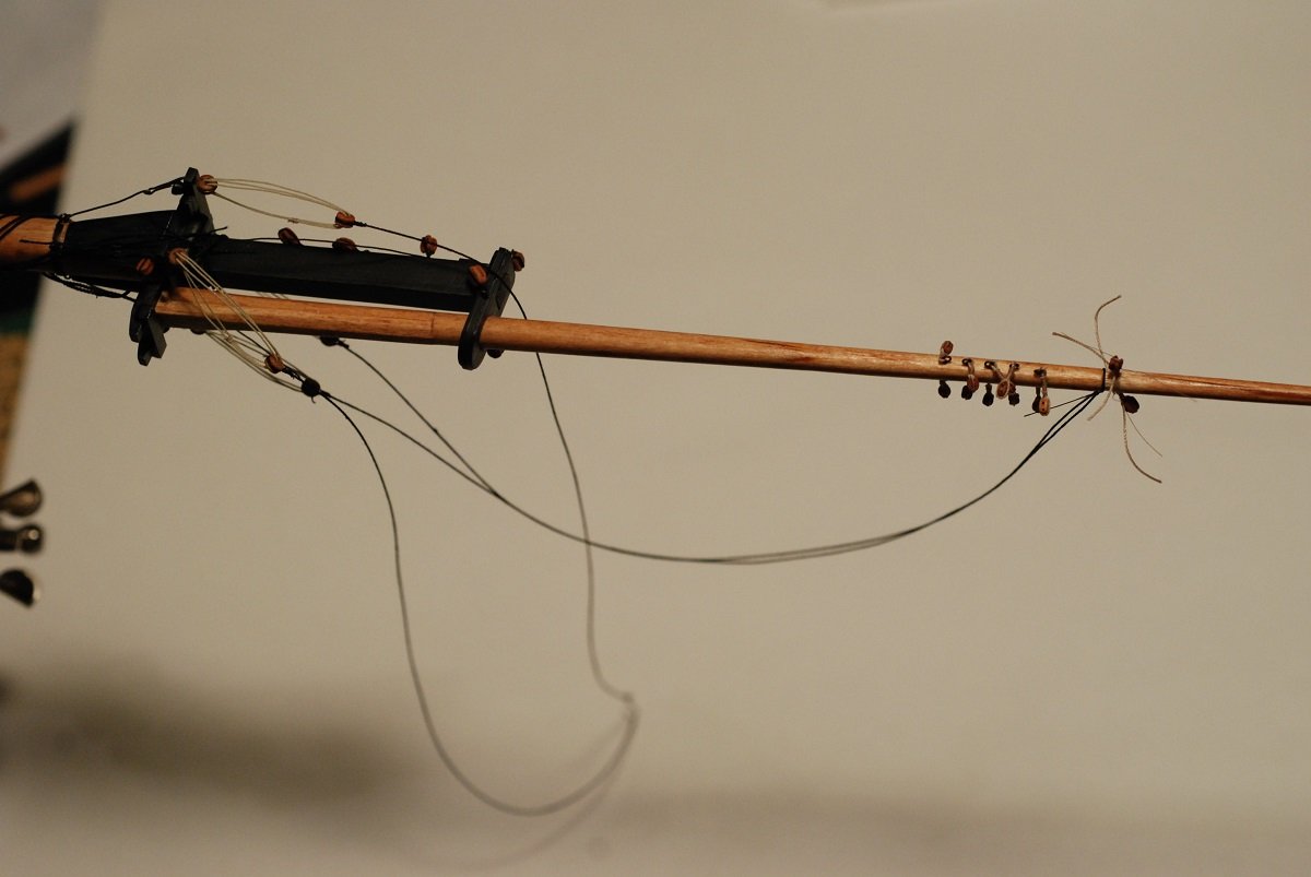
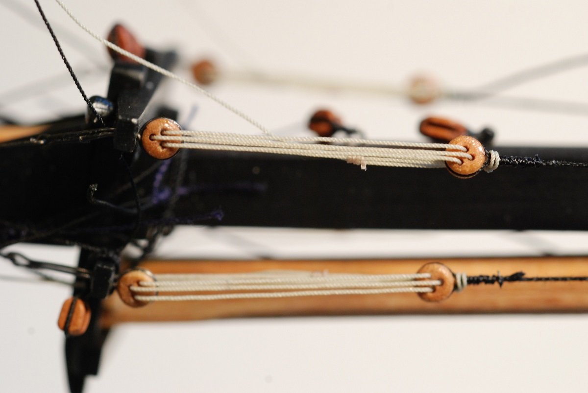
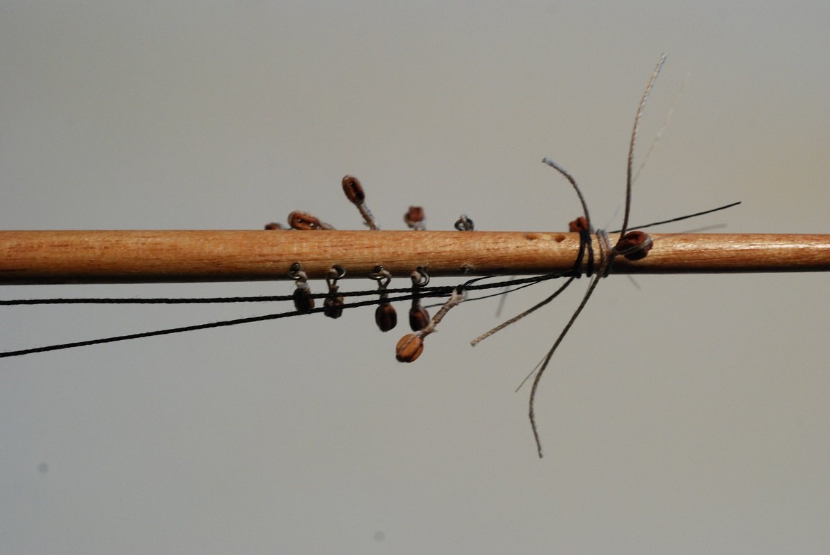
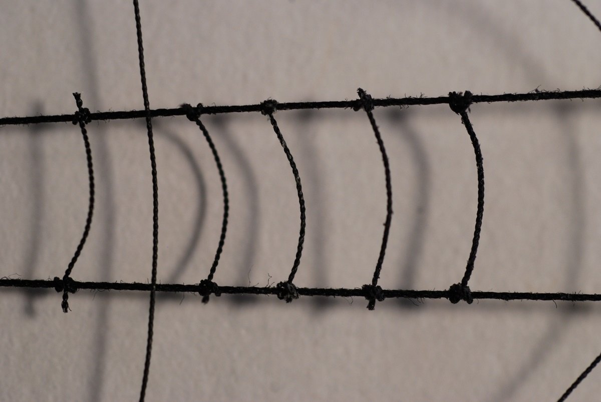
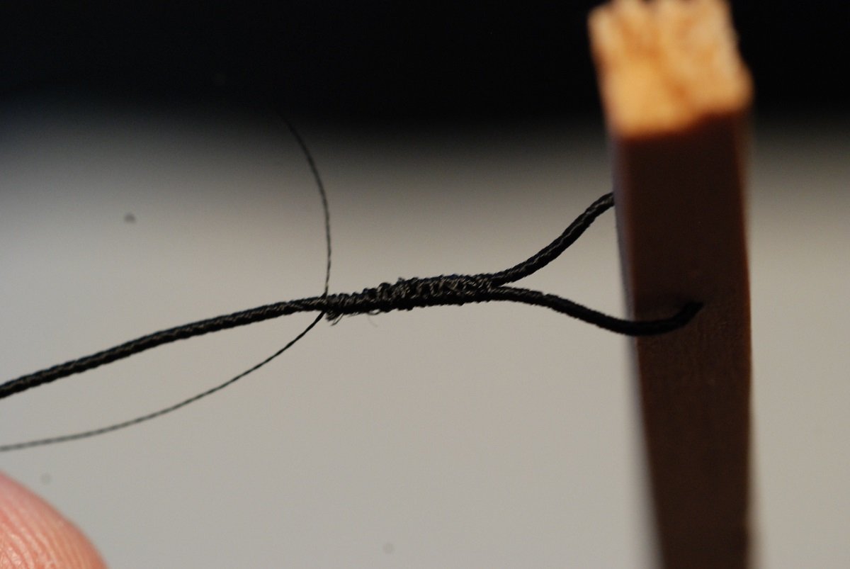
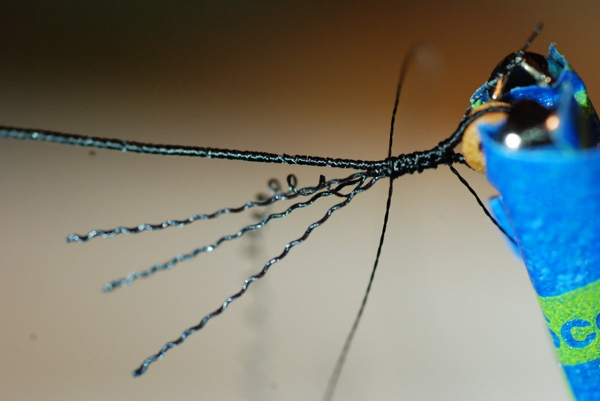
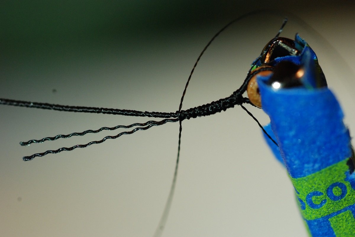
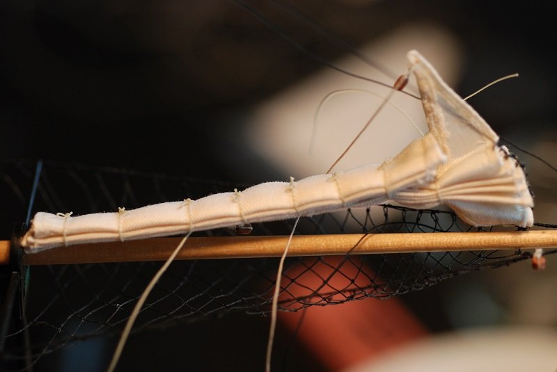
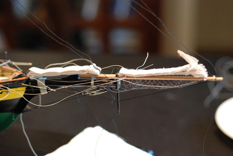
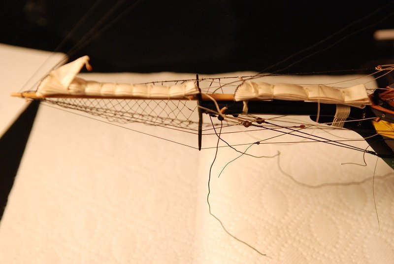
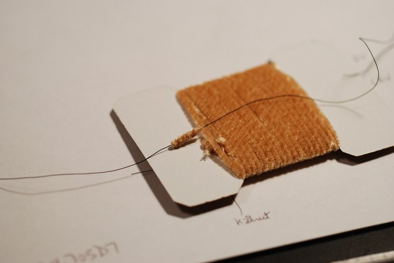
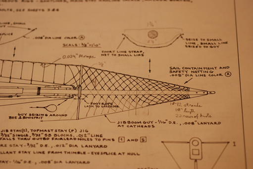
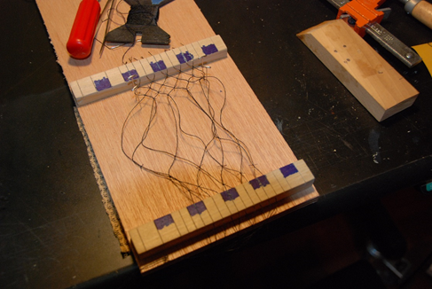
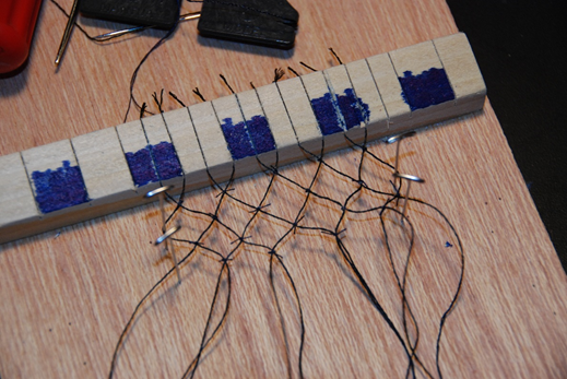
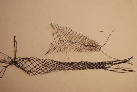
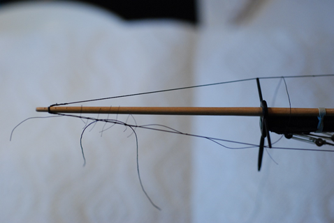
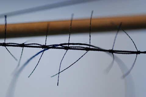
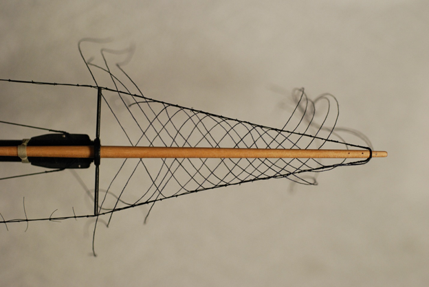
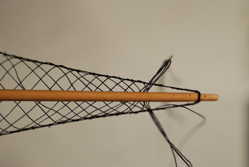
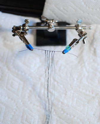
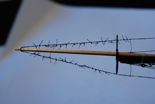
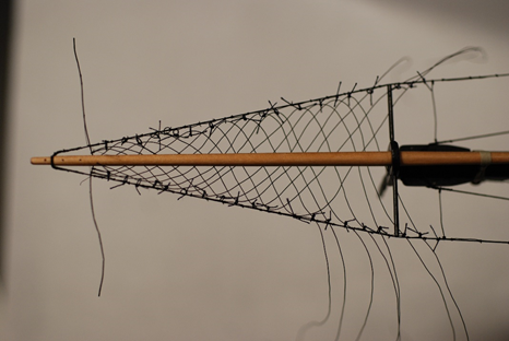
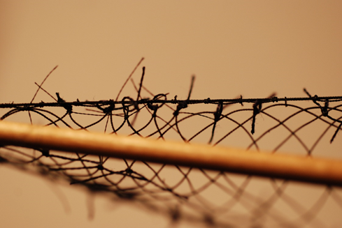
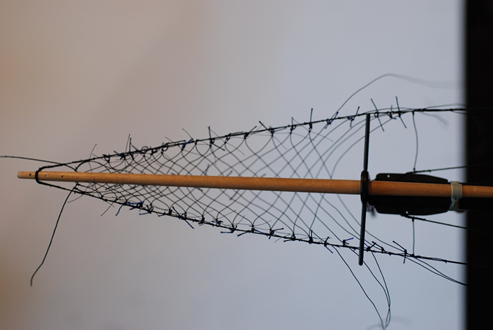
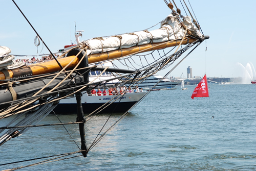
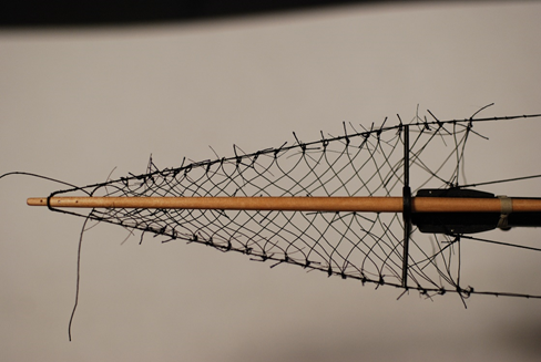
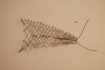
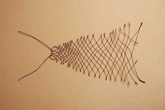
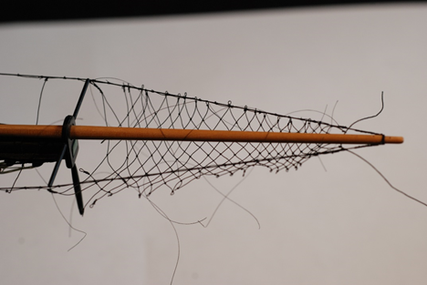
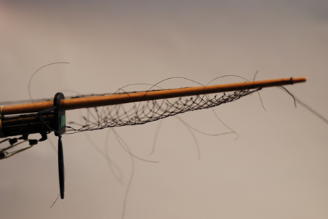
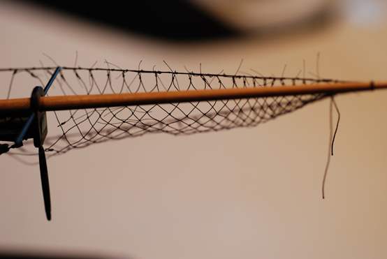
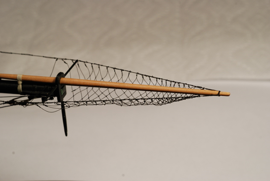
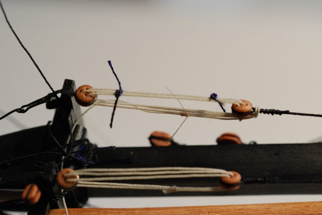
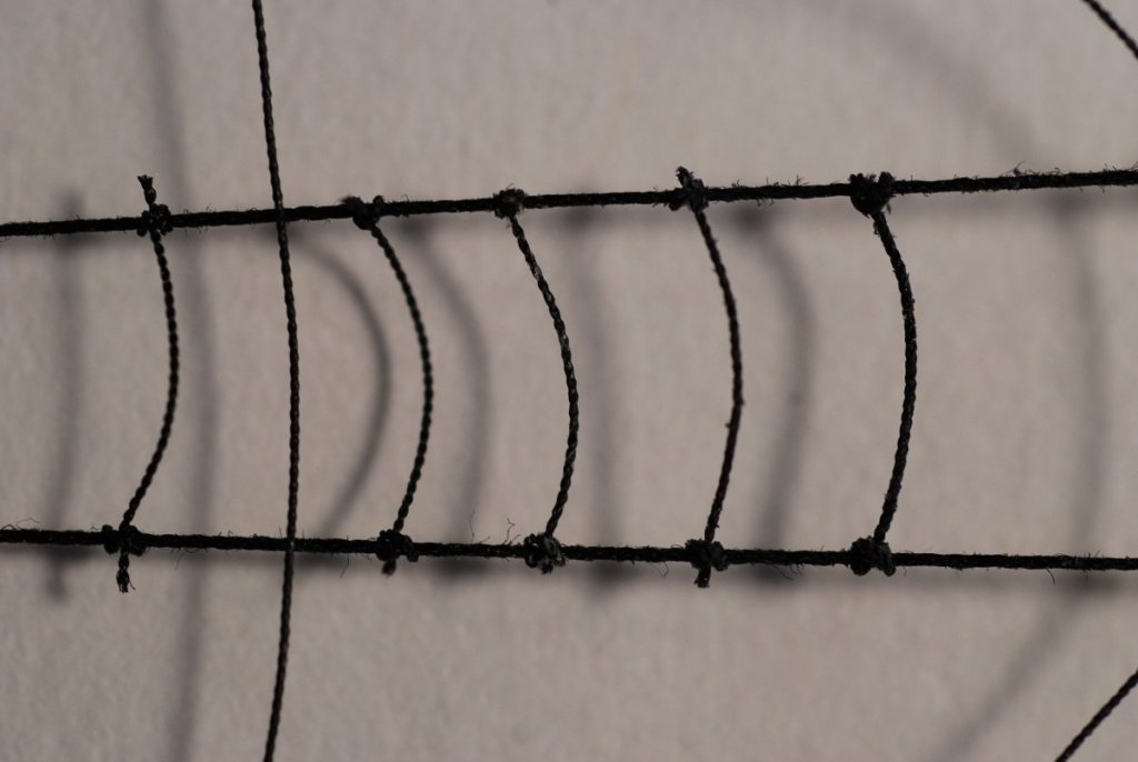
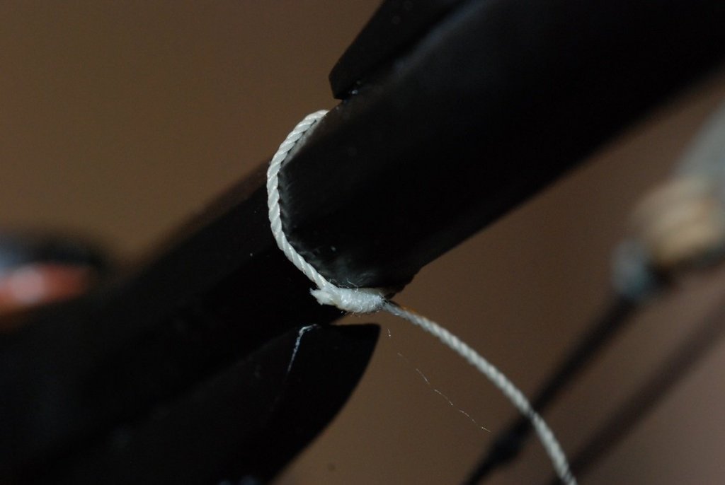
Since I bought the Pride 2 kit in 1995, many times have I looked at the bowsprit netting on the plans sheet and wondered how in the world I would go about doing that. Recently, though, it became apparent that I was at a point where I could start working on it. The bowsprit and dolphin striker had been installed, and the guys were in place. I had not yet started installing either mast, but had been working on the sails. I realized that trying to install bowsprit netting after having put in all the forestays would be difficult, as the forestays travel to the tip of the bowsprit and then travel back to the bow underneath the bowsprit. Those would obstruct the area of the netting. A year or so earlier, I had tried assembling a bowsprit net off the ship, using a jig that I built out of scrap. The blocks at the top and bottom have grooves cut in them. Using some coarse leftover line, I took about 10 strands and ran them between the blocks. The strands traveled in a zigzag pattern essentially parallel to each other, without actually crossing each other (like chain link fence). Fine line was used to attach the lines to each other. T-pins maintained the shape of the net at the edges. This wasn’t very satisfying, because the netting would have to have an overall triangular shape, with an apex and then widening as it approached the bow. Another jig was built that had more of a Christmas tree appearance. Work with that jig produced a net like is seen in the bottom of the next photo. (The net in the top of the photo is the final product that resulted from all these first tries.) Work with the jigs helped me realize that the netting would have to be a true netting, meaning that the strands of the netting would have to cross one another, instead of abutting one another where they were attached to each other with the finer thread. And the fibers would have to weave above and below one another to create a more stable structure. The question really became: is it possible to build a net off the model and then install it? Or is it necessary to build it in place on the model? Of course, the ultimate solution would be a combination of both. On the real ship, the netting does not attach directly to the bowsprit guys. The netting attaches to finer line that is intermittently seized to the guys. The next photo shows a 0.004” line being seized to the guy using very fine fly tying thread (Veevus 16/0). And a close-up: After attaching this line to each guy, a test run was made by running lines through these gaps on the guy and weaving an initial in situ bowsprit netting. It was clear that something would have to be done where the netting and the guys meet. Simply weaving the fibers through the gaps on the guys causes the line to very gently curve up to where it meets the guy. In reality, these parts of the netting need to look like sharp corners. It was also a puzzle what to do at the fore edge of the netting, where the fibers all came together. They could be gathered into two common points, but the fibers look too crowded and less net-like. In order to get the edges of the netting to be more orderly, and in order to make the fibers sit neatly, they were waxed. Plain beeswax by itself is not very pleasant, as it leaves a whitish residue that is visible on the line, especially if it is worked too much. But a piece of beeswax that has been colored with Transtint black dye can be used to coat the lines with no visible residue. This took some experimentation in order to get the granular appearance of the beeswax on the line to disappear, which typically involved heating the line by pulling it through tightly pinched fingertips and letting friction melt those waxy deposits into the fibers. They became much more orderly after that. So instead, the netting was begun using a single line that ran athwartships at the fore edge of the netting, and five lines were seized to that line. That gave a total of 10 fibers traveling aft that could be used to weave a bowsprit net. Next step was to install some loops along each guy that could be used as temporary attachment points for the netting, enabling me to create a netting in place while being able to remove it once I was happy with its shape. In order to get the netting to attach more realistically to these temporary loops, it would be necessary to seize the fiber of the netting as it came up to each of the attachment points on the guys, so they would not gently curve into the guys but would come to a focal attachment point. The guys looked pretty ugly after installation of the temporary loops, which were created with a generic, fuzzy sewing line. Fortunately that made it easier to identify which lines needed to be snipped later on, and which should be left alone. Now it was possible to take the 10 strands attached to the one line and set it at the tip of the bowsprit and guys, and begin weaving the netting. I pretty much weaved the entire netting, leaving the aft most edge open. Then it was time to go back and seize each fiber of the netting where it met the guy. The first photo shows the netting fully weaved, then the second photo shows the seizings going on. There are seizings on the first 5 points on the left side of the photo, and the points to the right remain unseized. Seizing usually involves 5 or 6 wraps, with the bitter end tucking into a loop under the wraps. These seizings were nothing more than a series of overhand knots, with the tails of the overhand knots wrapping around the line and a second overhand knot tied next to the first. The overhand knot was then finished with a square knot. While doing the seizing, it was necessary to include enough slack in the fibers so that the netting would droop below the bowsprit. Once the seizing was added to a particular point, it was no longer possible to adjust the amount of slack in that particular fiber, so this was a key step. Seizings also had to be added symmetrically, so that one side of the netting would not have more slack than the other. To give the netting more stability, temporary knots were tied in the netting in the centerline. Initially the idea was that at each point where the fibers of the netting crossed, a knot would be used to secure the two lines against each other. Here is a picture with nearly all the seizings in place. The temporary knots in the centerline are faintly visible under the bowsprit. On the real ship, the netting looks like this: I ran out of attachment points for the ends of the fibers at the aft end of the netting. You run out of room when there is the bowsprit cap and the dolphin striker protruding down from the bowsprit. So at the aft end of the netting, two of the fibers attach to the same point along the guys. This would turn out to be a temporary arrangement. A row of permanent knots was tied at the edge of the netting immediately inboard of the bowsprit guys and the seizings, in order to give the netting more substance for when it would be removed. At this point I was happy enough with the size of the netting overall that I created loops in the aft ends of each of the 10 fibers. The tails were left long, just in case. Once that was done, the netting could be cut off of the model. In the following picture, the temporary knots are visible along the centerline of the netting. These were replaced with permanent knots using Veevus fly tying thread. The permanent knots at the edge of the netting are visible, just inboard of the seizings. At this point, the netting was adjusted to get as much symmetry as possible. Two additional rows of permanent knots were added, between the row of knots in the midline and the knots at the edge. I decided not to tie knots at every single crossing point, because it seemed like the net was holding together fine without tying that many knots. Once I was happy with the overall pattern, I used Flexament to secure the knots, and the tails were cut off as close as I dared. Here is the final product. Ahh, that looks so much better… It was time to reinstall the netting on the model. I secured it as I had before, in terms of the spacing along each bowsprit guy, but now that all those knots had been added at all those crossing points, the netting no longer hung down beneath the bowsprit. It was in fact very flat, ruining the overall effect. The culprit was too much fore-and-aft tension on the netting, but this was easily fixed by changing the spacing of the attachment points of the netting. Now the netting did not extend as far aft underneath the bowsprit, but a nice consequence of this was that things were no longer crowded up in the area of the dolphin striker and bowsprit cap. This picture shows the netting attached at several points, with most of the attachment points still loose. From here it was a matter of getting all of the points attached and trimming away the excess line. At the aft end of the netting, there were two spare lines that were meant to terminate near the bowsprit cap, but they would no longer reach. I therefore attached these ends to another one of the netting lines. A compromise that you can see in the following picture: All points have been attached, and the only remaining task was to trim away the excess, leaving you with this: The droop of the netting is actually too much, and I don’t like how the netting gathers up about 2/3 of the way back. But otherwise I am happy with how it turned out. And I can put this task behind me! As long as I keep the bowsprit protected from inadvertent injury… This was an incredibly satisfying step to complete, as I had no resources to work with except the specifications on the plans and the images of the real ship. Many different steps required many different trials and errors to reach the final product.
- 60 replies
-
- 6
-
-
- pride of baltimore ii
- Model Shipways
- (and 1 more)
-
Thanks to you and your flag making tips, Dan!
-
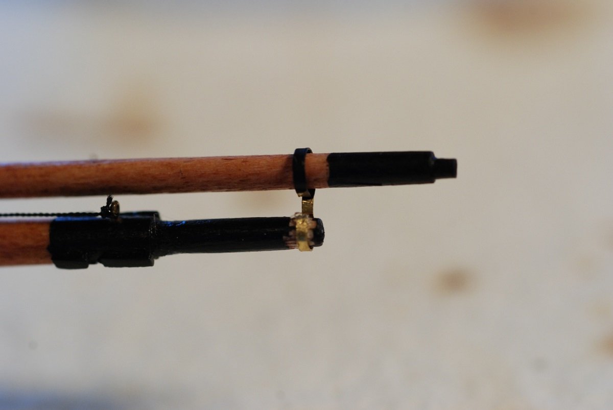
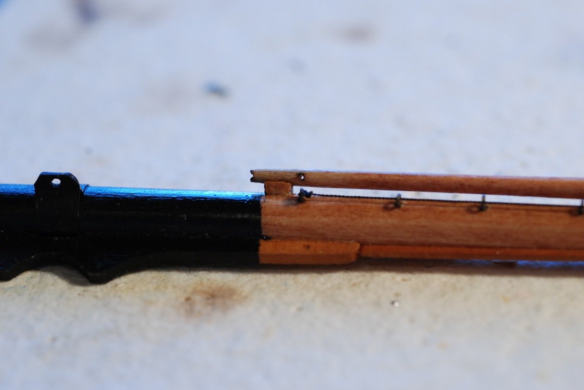
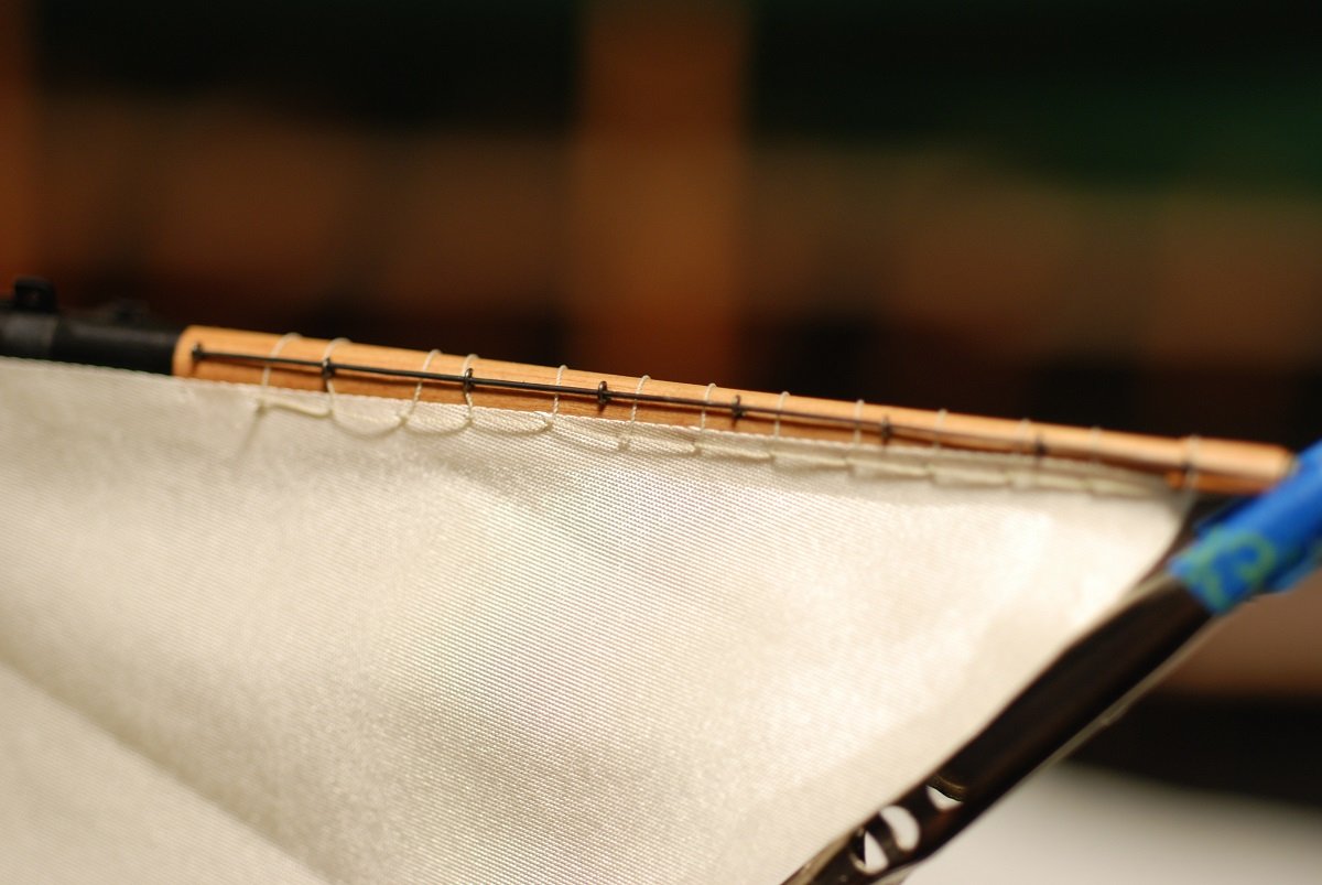
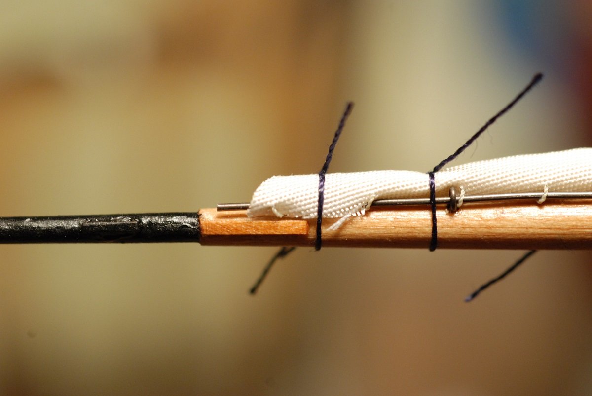
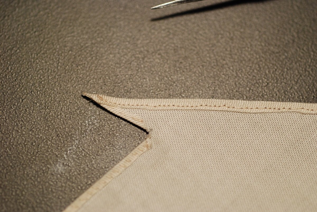
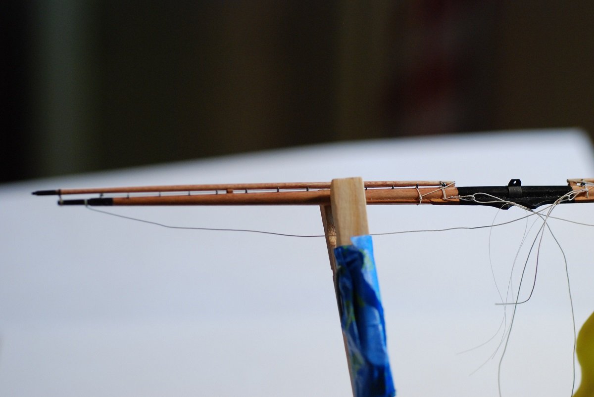
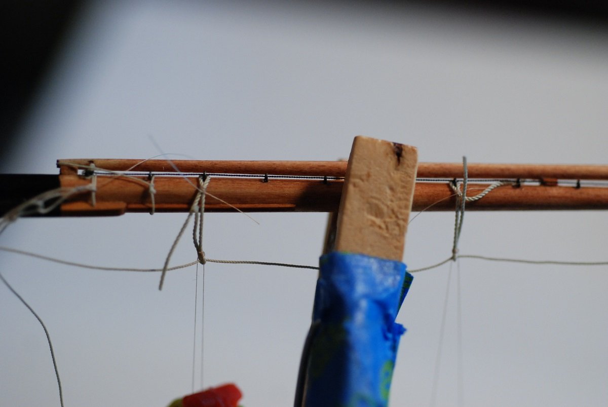
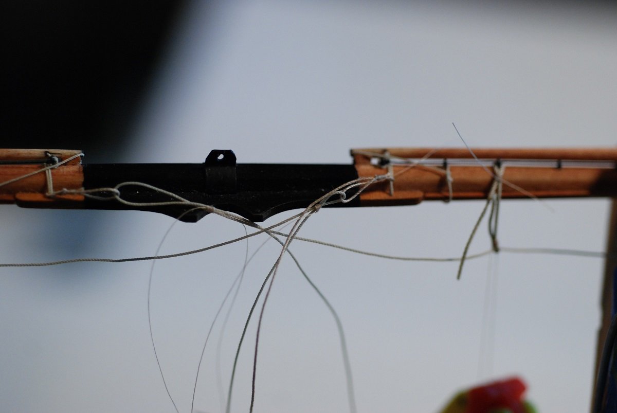
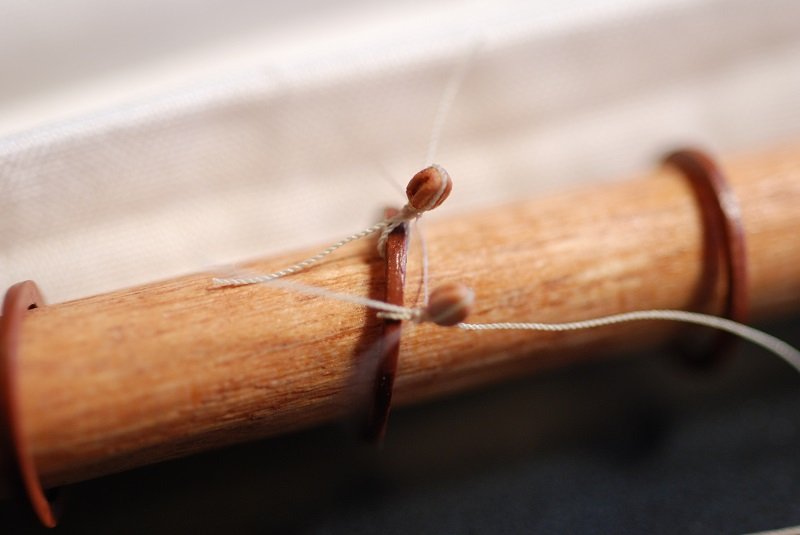
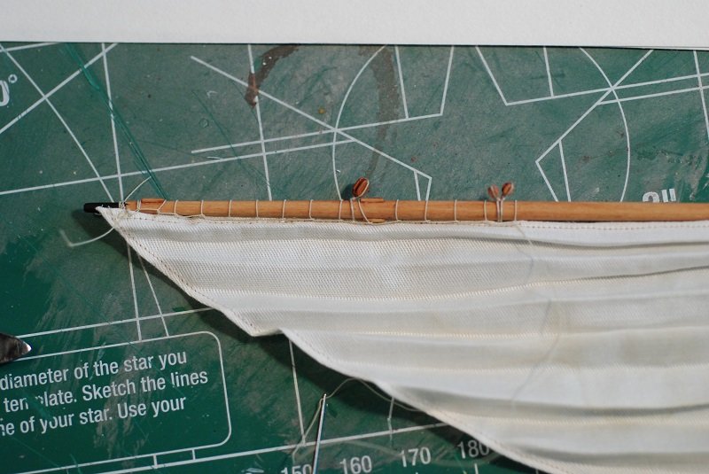
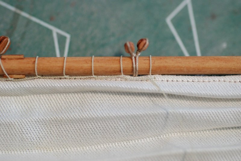
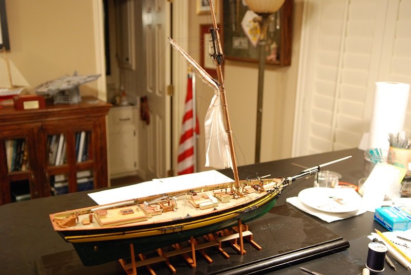
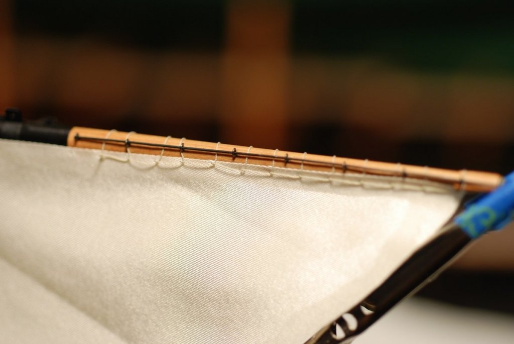
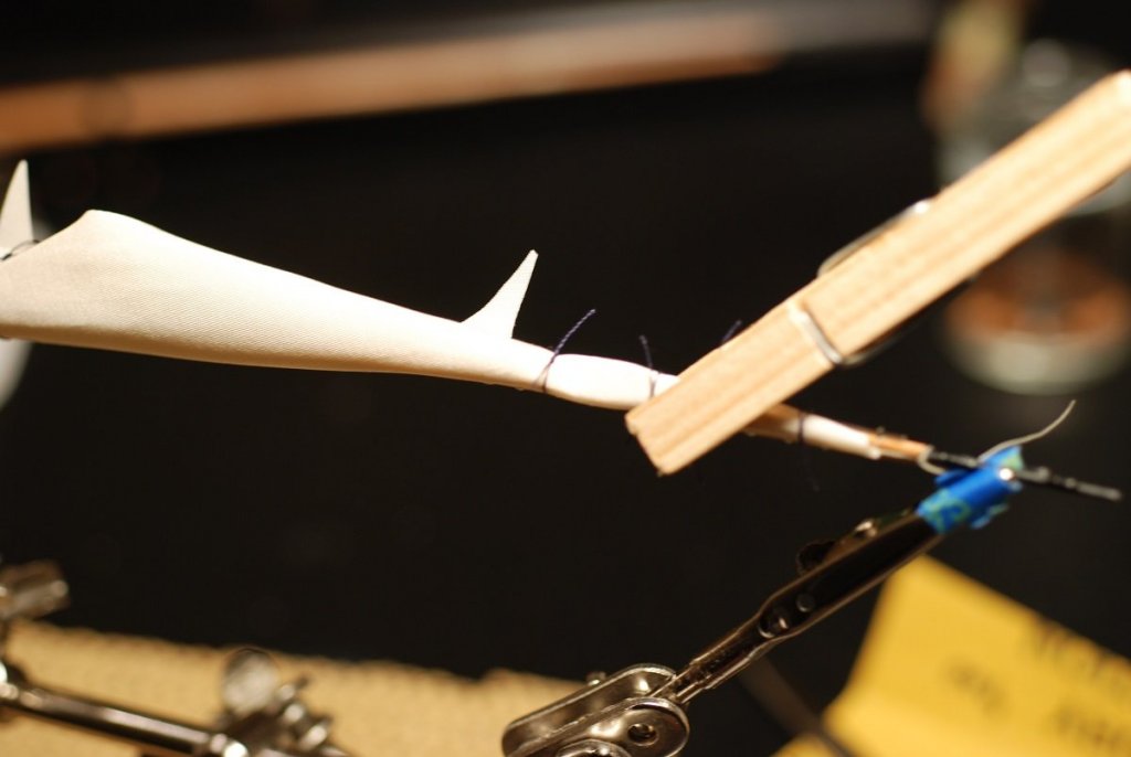
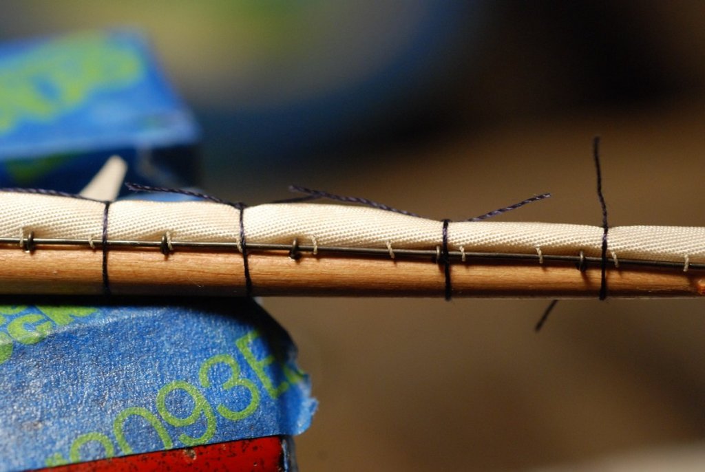
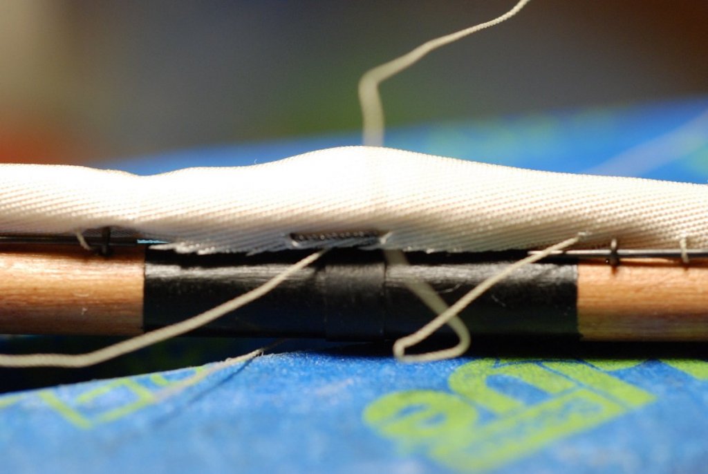
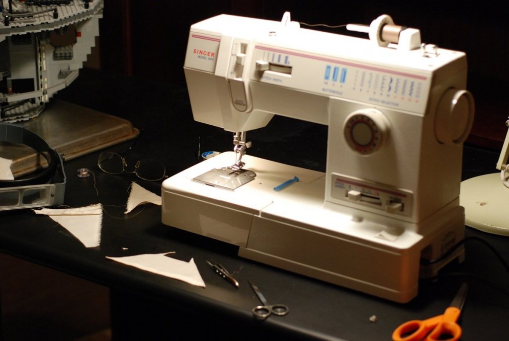
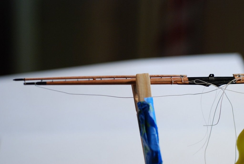
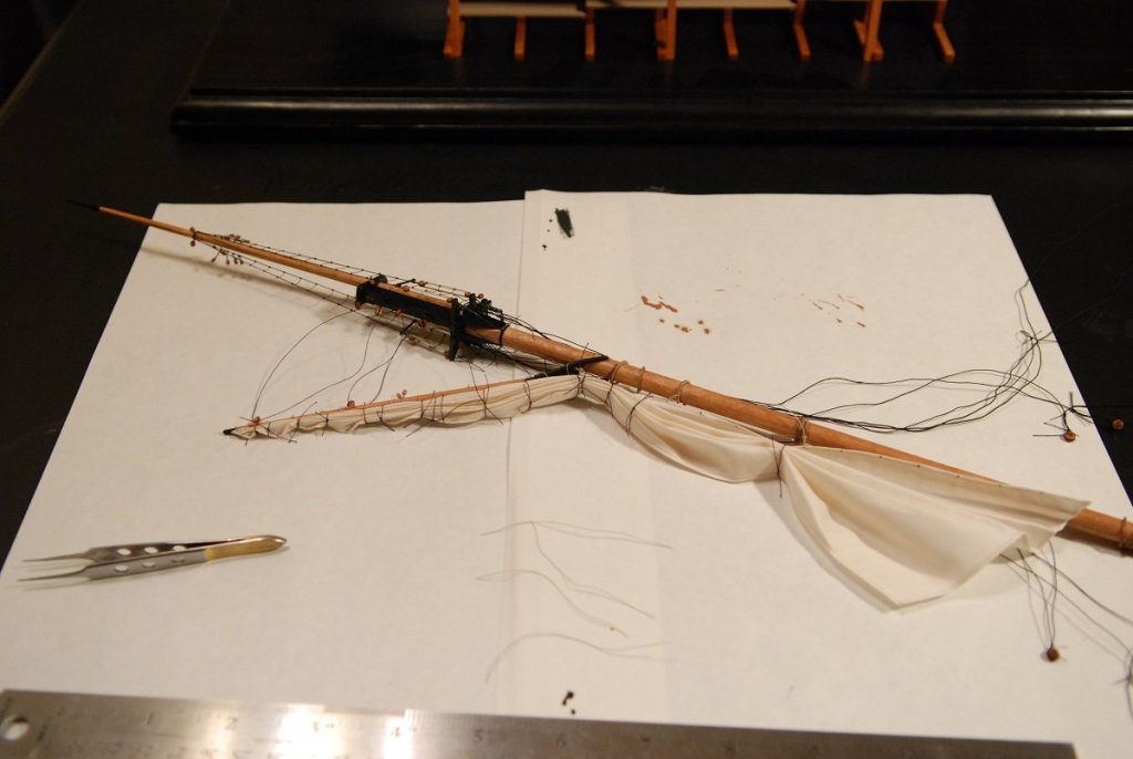
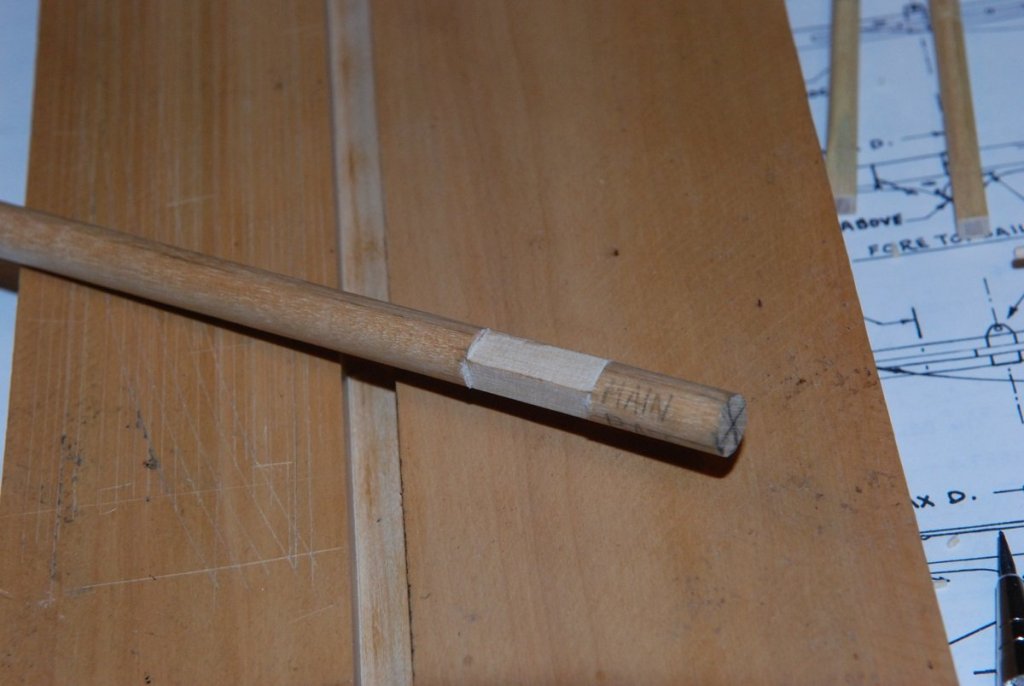
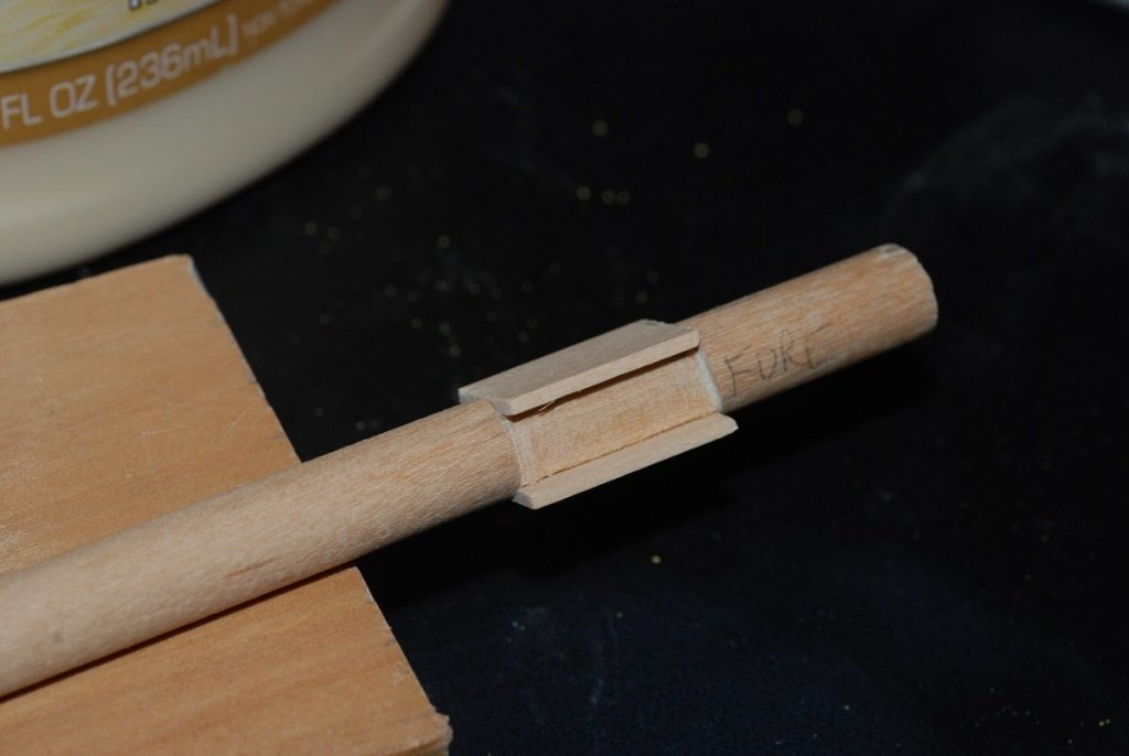
Time to move on to the fore topmast yard and get the sail bent on to it. I decided I wanted to rig the model with furled sails, trying to duplicate the look of the vessel at dock, as we saw it in Boston. But first, installing the studding sail booms required manufacturing of this metal bracket on both ends of the yard. I cut very narrow strips of brass and bent them around small dowels to create this piece. It was painted black after installation. The inboard end of the studdingsail boom is notched and has a small hole in it. This was my first attempt to install a sail on the yard. The fabric is a light cotton cloth called Belvedere cotton. I don’t remember how much I paid for the piece of cloth I got from the specialty fabric shop, but I remember thinking that it would cost a lot to buy enough fabric to make a shirt out of it. It felt very light with good texture. This piece is unhemmed, but the edge has been treated with an anti-fraying treatment. It colors the sail edge a little bit. The color of the sail is achieved with treatment with dilute coffee, like 2 ounces of coffee diluted to a volume of 1 cup. About 5-10 minutes of soaking the fabric in the coffee did the trick. Ironing it caused things to dry rapidly. The dyeing of the sail had to happen before treatment with the anti-fraying compound. The shape of this cloth was cut so that I could achieve a nice folding effect as the sail was gathered onto the yard, plus it would have two “corners” sticking out down low to simulate the clew points that would show when the sail is furled. The sail was carefully sewed on with a running stitch. I couldn’t pull too tightly without tearing the edge of the fabric, even with the treated edge. Then the sail was furled and temporarily secured with black thread. The clothespin would hold the fabric while I tied on the temporary furling lines. Looking ok so far… Hmm. Now the unhemmed edge of the sail is beginning to show where the tack of the sail is tied off. Looks a little rough. And I couldn’t hide the unhemmed edge of the sail in the center of the yard, as it kept showing itself as I attempted to tuck it under the rest of the sail. The black stitch was an attempt to pull it back under the rest of the furled sail. So at this point I gave up on the idea of a sail with an unhemmed edge. Fortunately we have a sewing machine around the house, so it was time for me to learn sewing skills. My wife and my mother in law were able to give me guidance on its use. Regular sewing thread stood out way too much against the fabric of the sail. I ended up using fly-tying thread for the hemming. I had to re-cut the fabric piece for the sail, of course, and allow extra fabric at the edge where a hem would be created. The hem was sewn as close to the folded edge as I could get it (not 1/16” away but certainly less than 1/8” away, so we’ll call it 3/32” wide), then I had to go back and carefully cut away the excess fabric without cutting into the stitch line. A lot of time and effort spent on learning how to sew tiny hems like this, but the look of the sail is much cleaner now. Here I have tied on a couple of rigging blocks in the center of the yard. Some of these required multiple tries because the block’s seizing sometimes didn’t hold when put under strain. This is how the furling lines came to look. The texture of the fabric looks very coarse on close-up imaging like this, but when you back away it looks very clean. The sail is fully installed. Footropes are now being installed on both the upper and lower yards. I spent time trying to coax the footropes to hang down as if under the influence of gravity. I learned that there wasn’t much point trying to work on that at this time; it would have to be addressed once the yard was installed. The footropes attach to the yard in a complex little arrangement as shown above. Those loops would be tightened up so they are much smaller in the final arrangement. This is one of the pendants holding the footrope in place. As of June 28, 2018, the model is officially finished! Here is a preview: Now I just have to fill in all the details between 2016 and 2018!


- 60 replies
-
- 6
-
-
- pride of baltimore ii
- Model Shipways
- (and 1 more)
-
PS: How do I end this page of this post and roll to another page? Or is it happening automatically, without me having to do anything? This seems like an awfully long post!
-
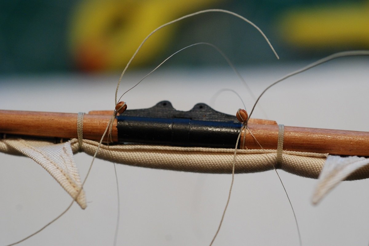
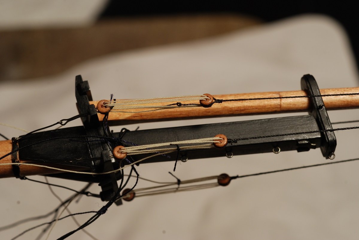
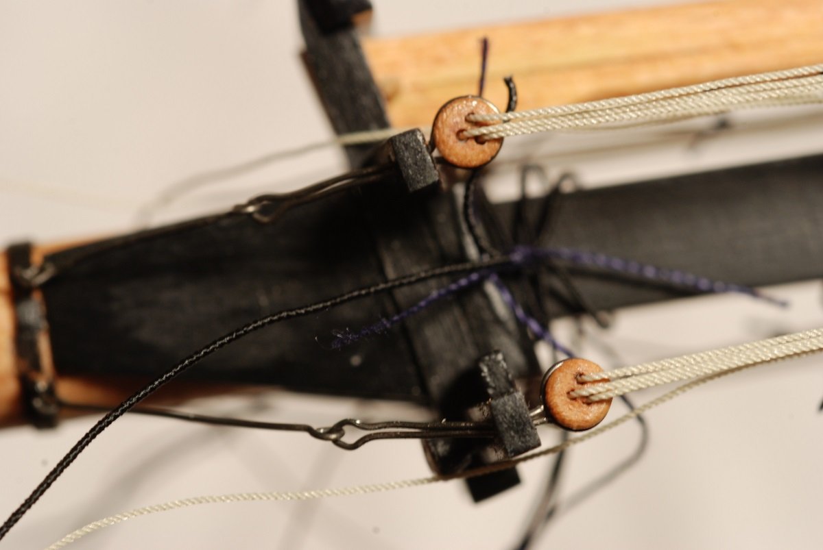
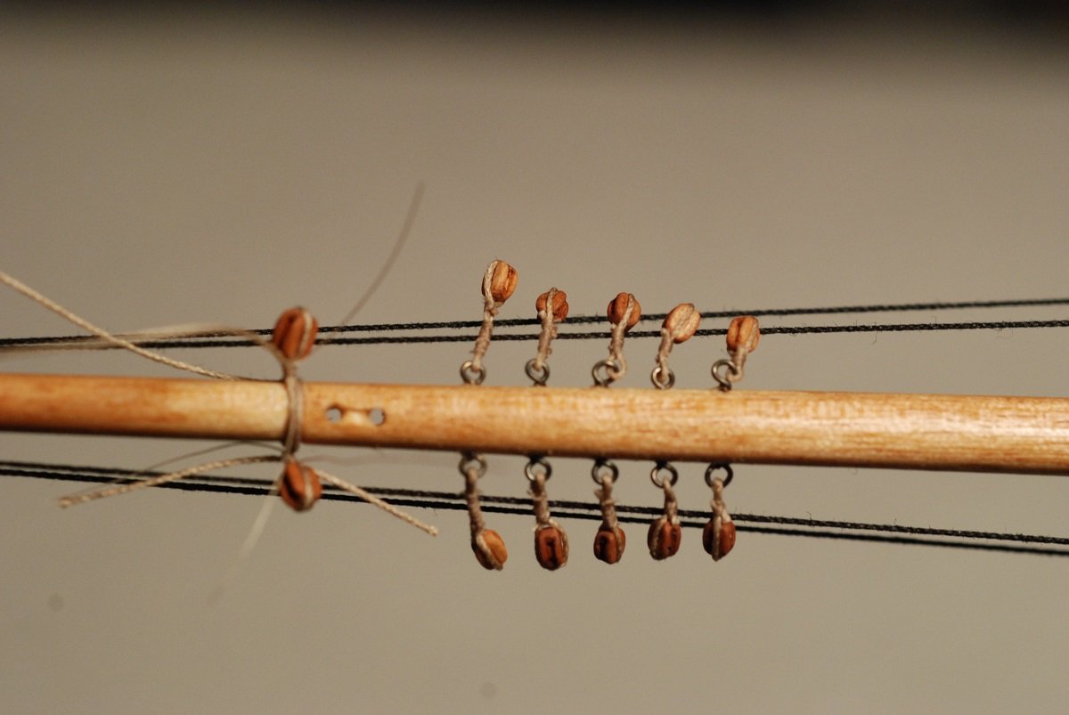
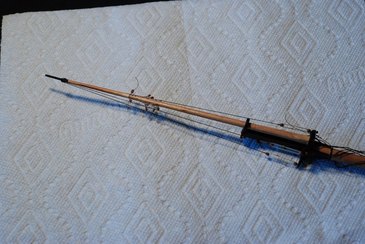
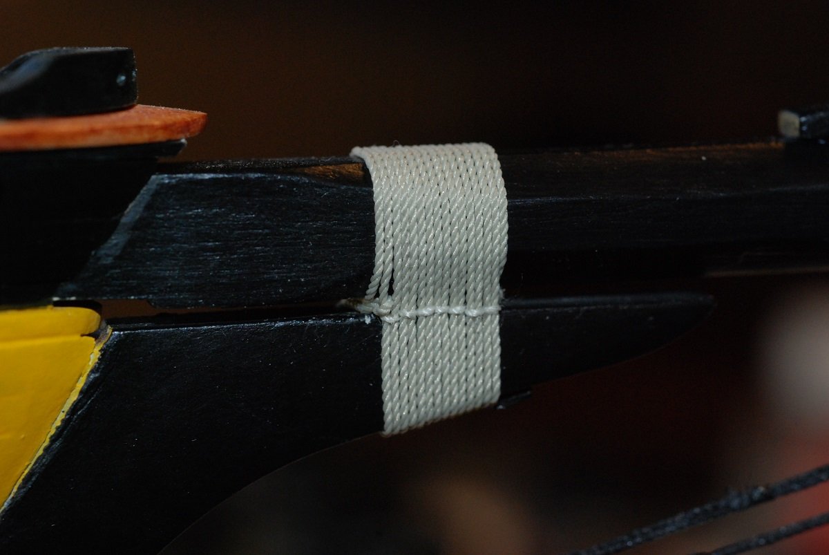
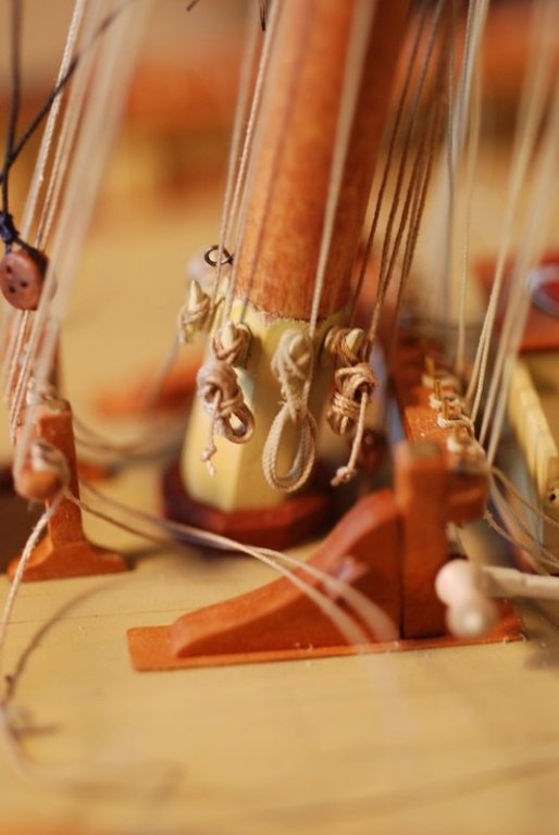
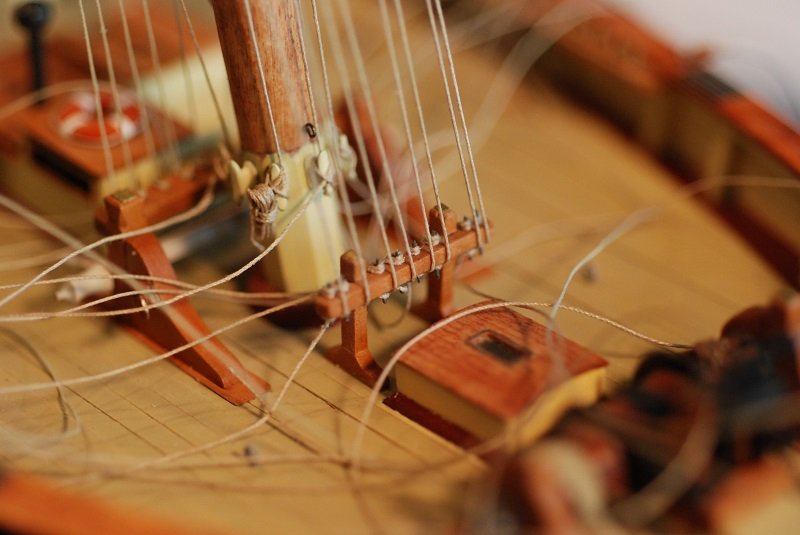
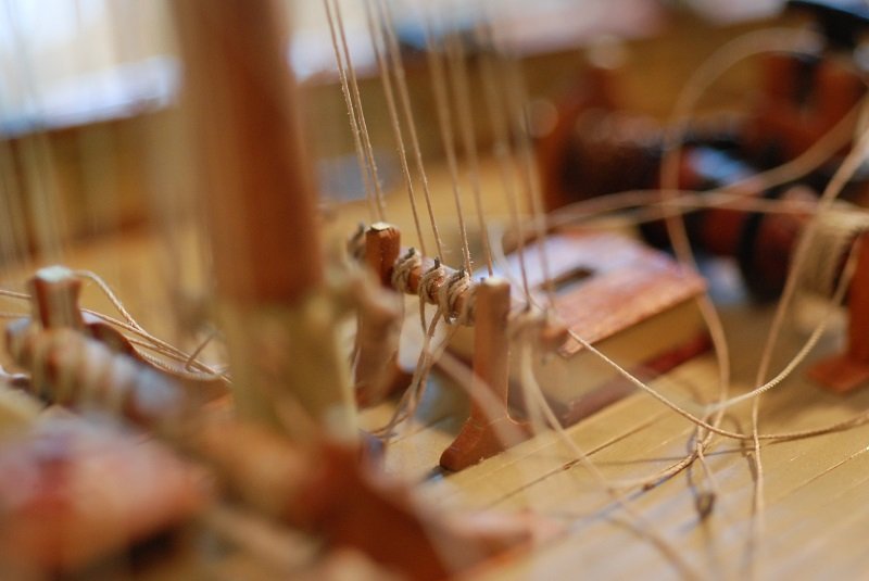
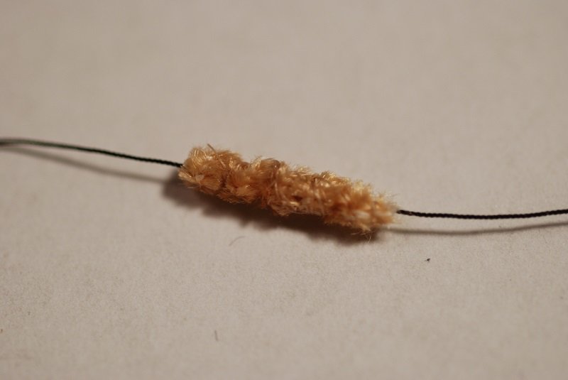
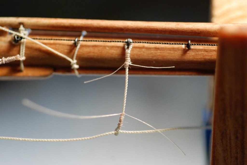
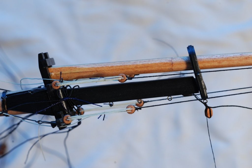
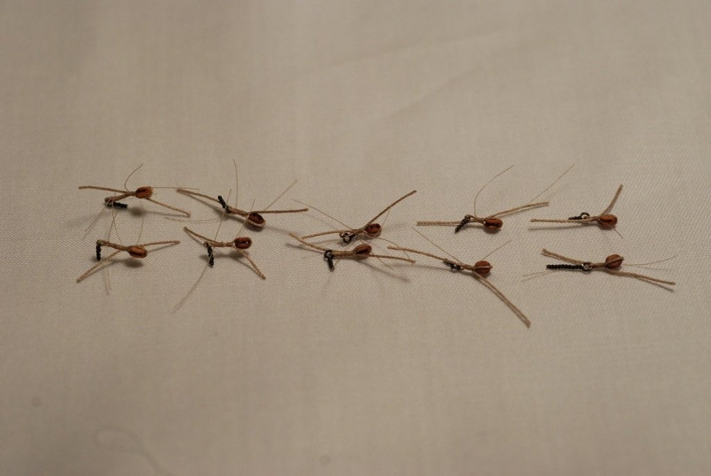
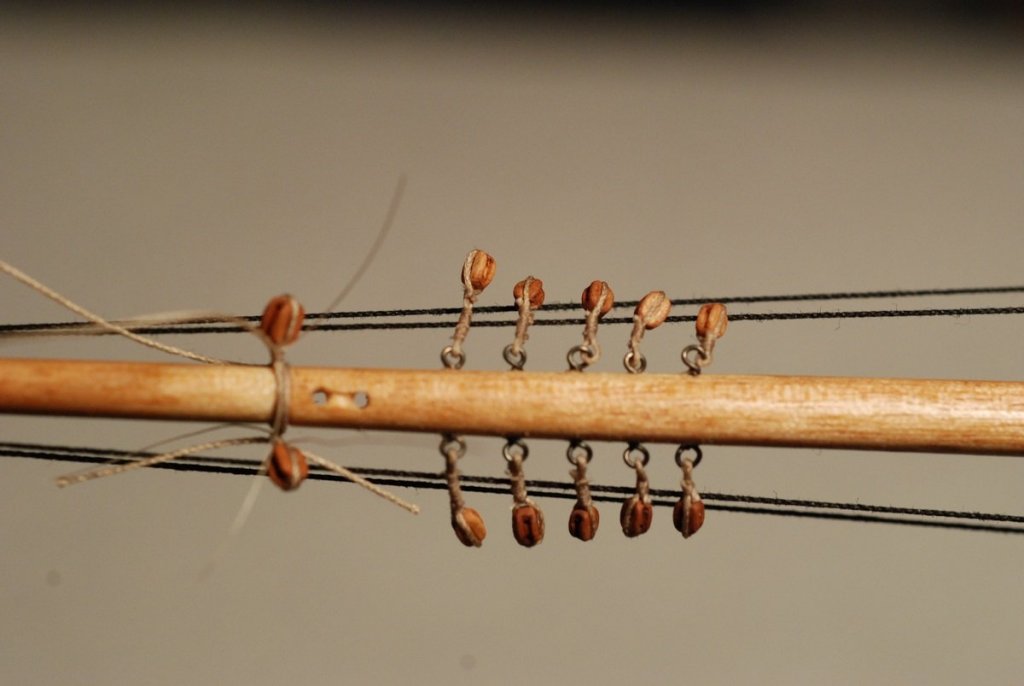
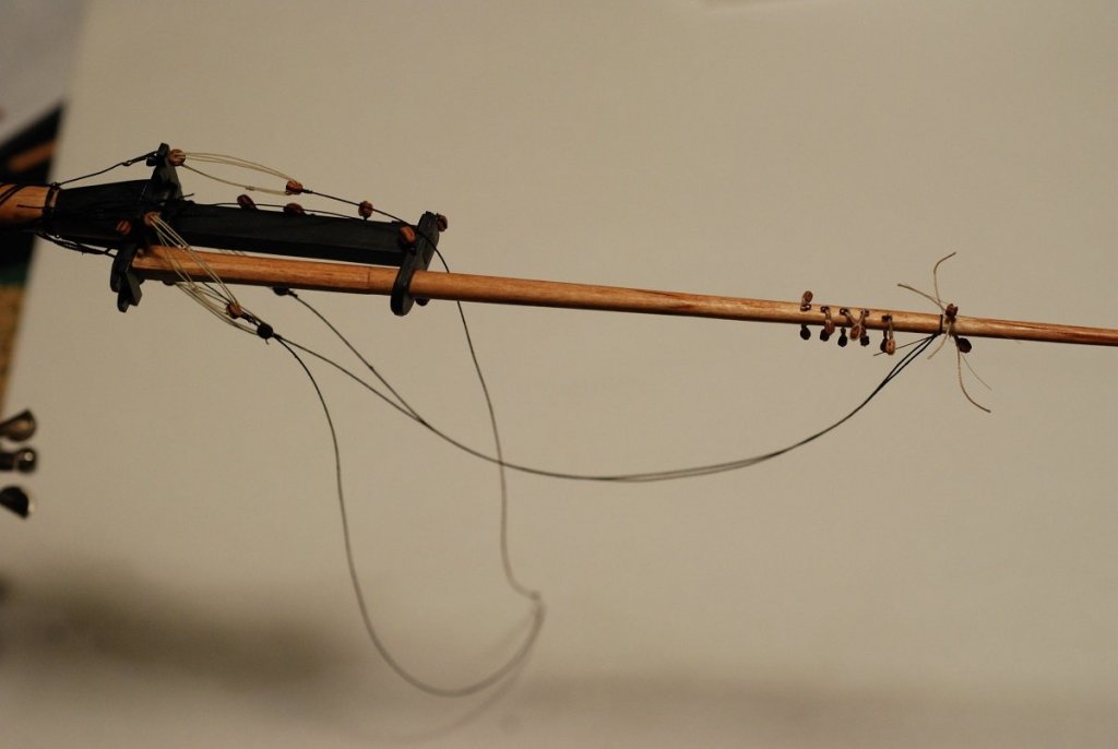
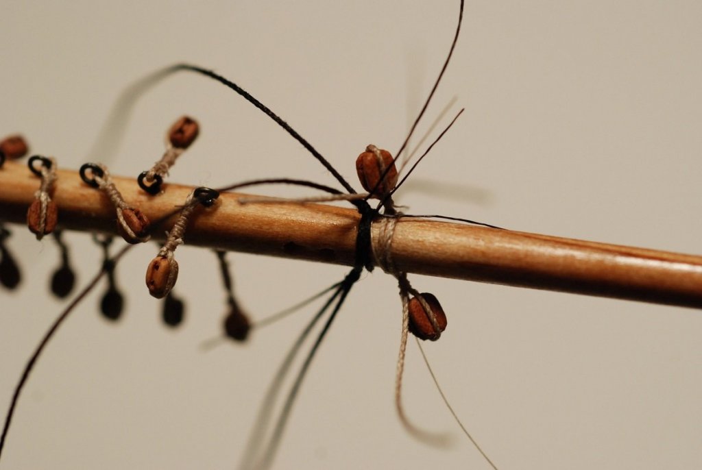
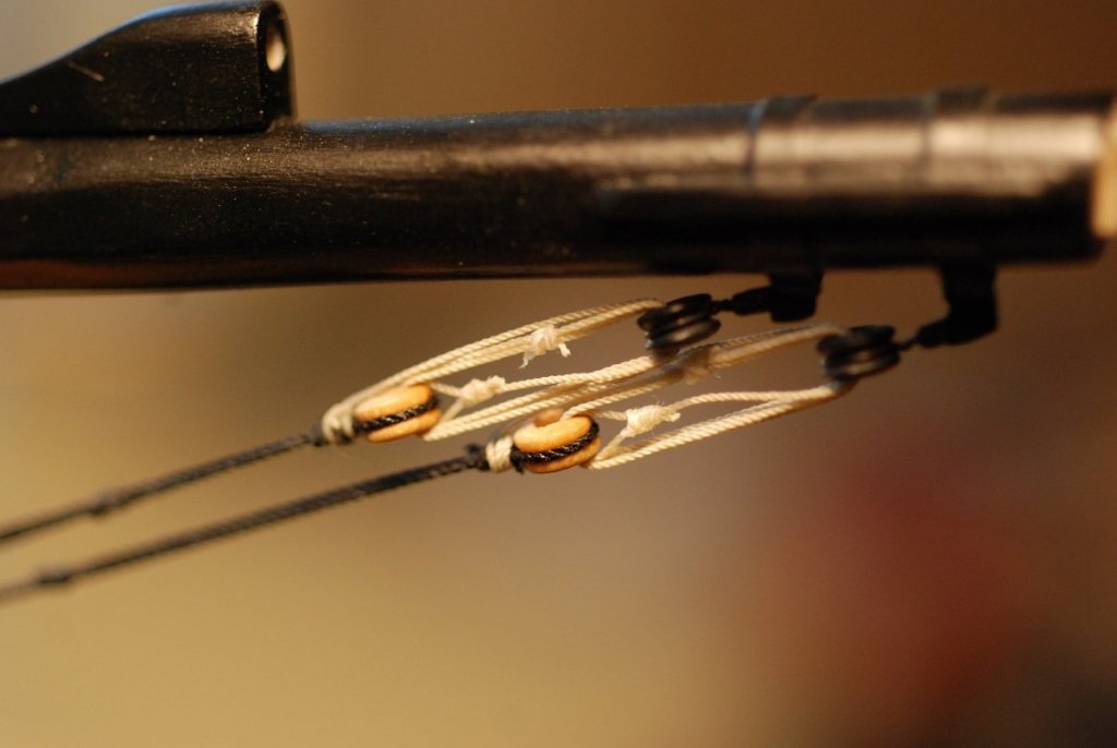
OK, I need to get rolling along. I am posting this in May 2018, and I am only up to mid 2016 in my descriptions. Plus the model is almost entirely finished, and I am anxious to get up to speed on how things actually look. Next topic is to start assembling the fore topmast to the foremast. I decided not to permanently glue the topmast to the foremast, in case for some reason it ever needed to be disassembled. Like in a restoration. God I hope I never have to do that. Anyway, shrouds with deadeyes were installed on the topmast, and deadeyes stropped with wire had to be installed in the trestletrees. The wire installation was a tricky assembly because the stropping had to run through the wood of the trestletrees, then come down and form a loop for another wire to attach to. Then that wire extended down to the mast, where a black band representing an iron hoop had eyebolts sticking out of it. And with all this, a sense of scale had to be preserved. No painting of the wire was needed since I had a supply of black wire in various sizes. Sitting in front of the trestletrees and wires is one of the shrouds, which is Morope line that has been served with fine fly-tying thread. The deadeyes were then threaded, and the ends of the lanyards were seized to one of the other strands of the lanyards using a “West country whipping”. This is one of the 10 (paired) blocks installed on the fore topmast that are used for the control lines of the fore topsail yard. Each pair of blocks were attached to eyebolts, with pendants of increasing length depending on how high they were attached to the topmast. They kind of look like bugs. And here are the blocks attached to the fore topmast. The pair of blocks further up are seized directly to the mast and are not attached via eyebolts. In the course of rigging the foremast and fore topmast, I suddenly realized I had installed the topmast shrouds so that they ended too high on the topmast, extending nearly to the very top of the topmast. In the photo below, they should end at the level of the highest pair of blocks seized to the topmast. I was concerned that this meant I would have to completely cut the shrouds and start over again. However, it was possible to physically loosen the seizings holding the shrouds near the top of the topmast, then cut the seizings away. The shrouds were then slid down below the top pair of blocks. New seizings were applied using 6/0 Unithread fly tying thread, and secured using Flexament. Now it was just a matter of taking up the slack at the level of the four deadeyes by the trestletrees. I took advantage of the opportunity to re-do how the lanyards were rigged. They previously were tied off using a West country whipping that joined the end of the lanyard to one of the other strands. The picture above shows one deadeye pair (the lower pair) with the older rigging arrangement, and the upper deadeye pair with the lanyard wrapped twice around the shroud where it is seized to the deadeye. The lanyard then comes back down and is seized in parallel with one of the other lanyard strands. This more accurately reflects the reality on the actual ship: I was left with two deadeye pairs that were spaced wider than the other two. This was because I prematurely cut two of the shrouds before making sure I was happy with the overall length. To fix that would require re-doing the shroud completely. I figure that this model is going to serve as a living example of how to gradually improve on how you are doing things. There, that’s better. Both lanyards are now rigged more accurately. I also realized at this point that the 5 pairs of blocks I had so carefully attached to the topmast using eyebolts needed to be moved off the topmast and attached to the shrouds. Here, the top pair of blocks has been detached and stropped to the shroud. To give each block a shelf to attach to, I first tied an overhand knot onto the shroud that would keep the block from sliding downward. I then seized a pendant to the shroud with several loops of fly tying line that was run through the loop left behind after the pendant was separated from its eyebolt. In this way, there wasn’t a need to redo each of the pendants that the blocks were attached to. I don’t have close-up photos of the final product after all the shrouds had been re-reeved and the blocks stropped to the shrouds. Putting ratlines on the shrouds seems like a simple enough idea before you start. Of course, which size line to use? Morope vs Syren line? How to secure it to the shroud? Actually, the biggest problem was how to take line that wants to do what it wants to do, and convince it to drape downward like ratlines should do. Especially when dealing in fine line like 0.004” or 0.006” Morope. Then there is the matter of making the clove hitches behave. They want to spring back open no matter how tightly you pull them closed. A lot of these problems were overcome with beeswax. Beeswax helped to stiffen the line so that it would take the desired draping shape. It also helped to close up the clove hitch knots and get them to stay closed. But it also gives black line a visible coat of thick grainy buildup that is unattractive. The solution there was to take a chunk of beeswax and dye it black with Transtint dye. Doing this actually made the shrouds to look thicker and more realistic. The best ratline in the picture above is the middle one, appropriate looking scale while the line looks smoother than the ratlines on the left that look more bumpy in appearance. The ratlines on the right were done with thicker line, and with less care to make sure that excess wax had been removed from the line. This is a look at the finished topmast shrouds. The foresail and fore gaff have been temporarily attached to the foremast. In the upper left hand corner of the picture you can very faintly see the pendants and 5 paired blocks now attached to the shrouds. Next up: Sailmaking and bending sails to yards!


- 60 replies
-
- 6
-
-
- pride of baltimore ii
- Model Shipways
- (and 1 more)
-
Thanks Dan. Good to know that is you! Greatgalleons, where in Texas are you?
-
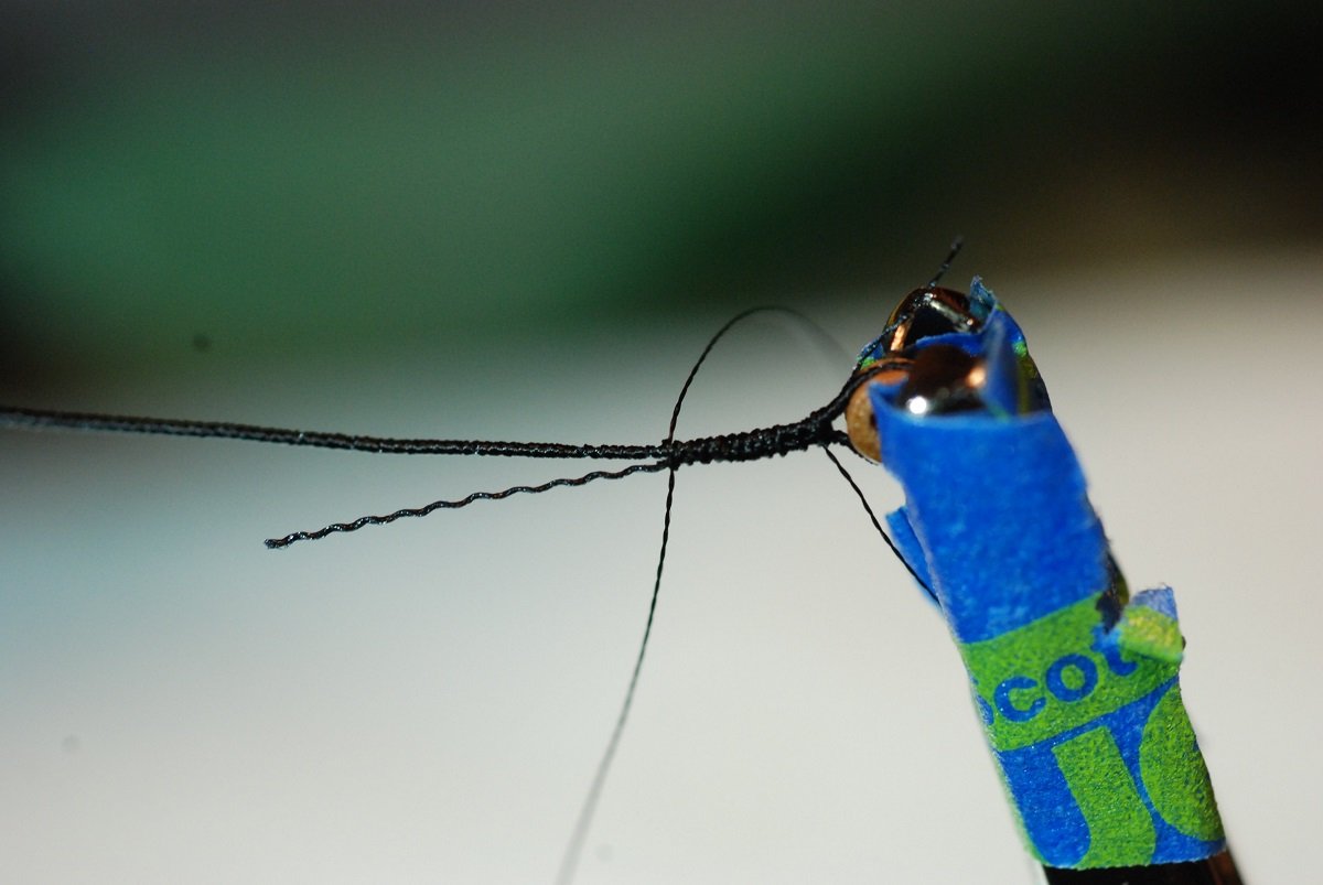
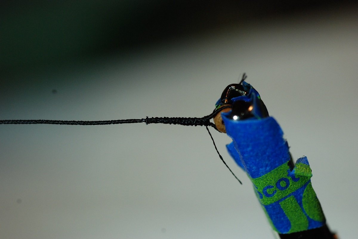
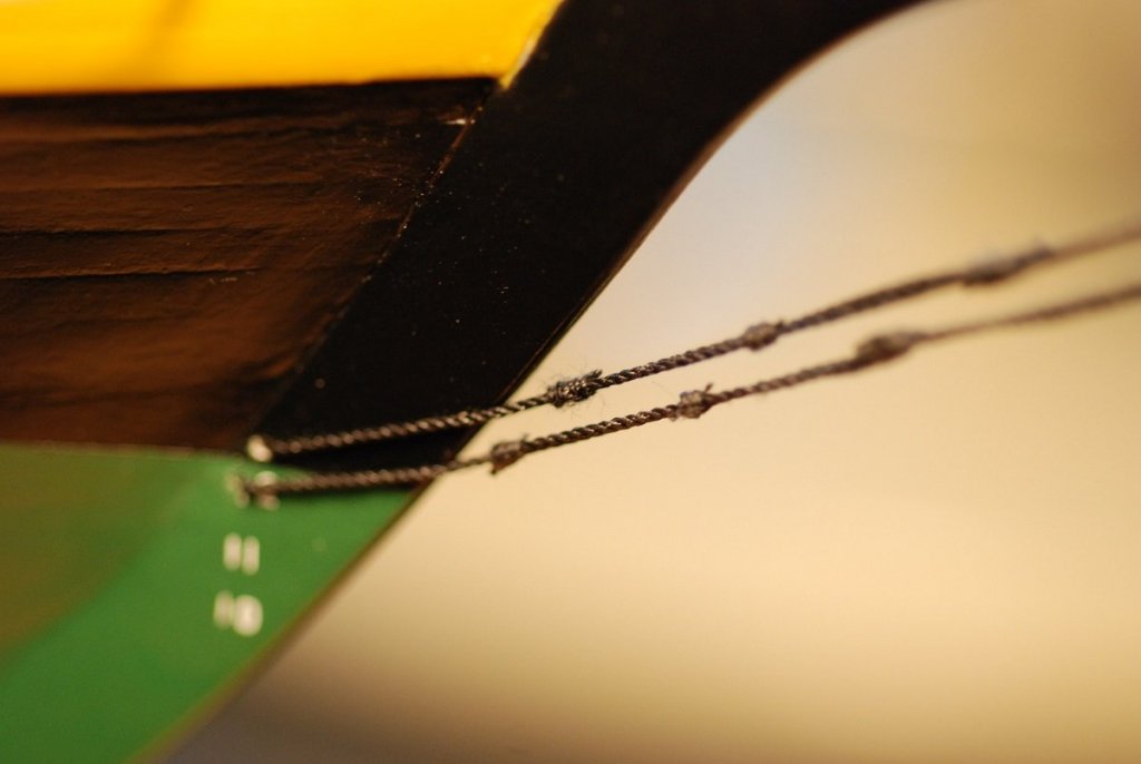
This is a side topic to the builder’s log. In fact, I may have posted this series already to the forum. When working on the bowsprit rigging, I found myself looking for a better way to seize a deadeye within standing rigging such as the bowsprit guys. For the guys, I used 0.010” Morope served with fly-tying line, which gives a very smooth look to the final product. Initially, I simply wrapped the served line around a deadeye and then applied a long seizing, then cut off the stub of the served line. This gives a very shelf-like appearance to the seizing. I felt that kind of appearance might be ok for the shrouds, but for the bowsprit guys I wanted a more tapered appearance. Usually, when I do a seizing, it is the kind that involves 6-8 wraps around a loop, then thread the line through the loop, then pull the loop closed, etc. etc. However, I found that when I tried to apply that kind of seizing to line that has been served, there is too much friction between the seizing and the serving to allow you to slide the seizing along the line. So instead, I simply created a long seizing that would not have to be moved, by using multiple consecutive overhand knots on alternating sides of the served line. I learned later that this is called a “West Country Whipping”. That is what is depicted in the photo above. The photo also shows that the seizing (whipping) covers the area where the shroud stub is cut off, with an abrupt change in the caliber of the whipped segment. In order to give a more tapered look, here is what I did: Start whipping around both ends of the served line. Cut the end of the served line that will be discarded, allowing the serving to unravel and allowing the underlying Morope to separate into its 3 separate strands. Let the Morope unravel all the way up to the last wrap of the seizing. Snip one of the 3 strands, then continue the seizing. Snip another of the strands, then continue seizing until you nearly reach the desired length of the seizing. Then a few more wraps to finish it off. A nice, tapered deadeye seizing that makes the bowsprit standing rigging look a lot cleaner. Like I said, I don’t plan on using this technique for the mast shrouds.


- 60 replies
-
- 3
-
-
- pride of baltimore ii
- Model Shipways
- (and 1 more)
-
Thanks for posting, Kevin!
-
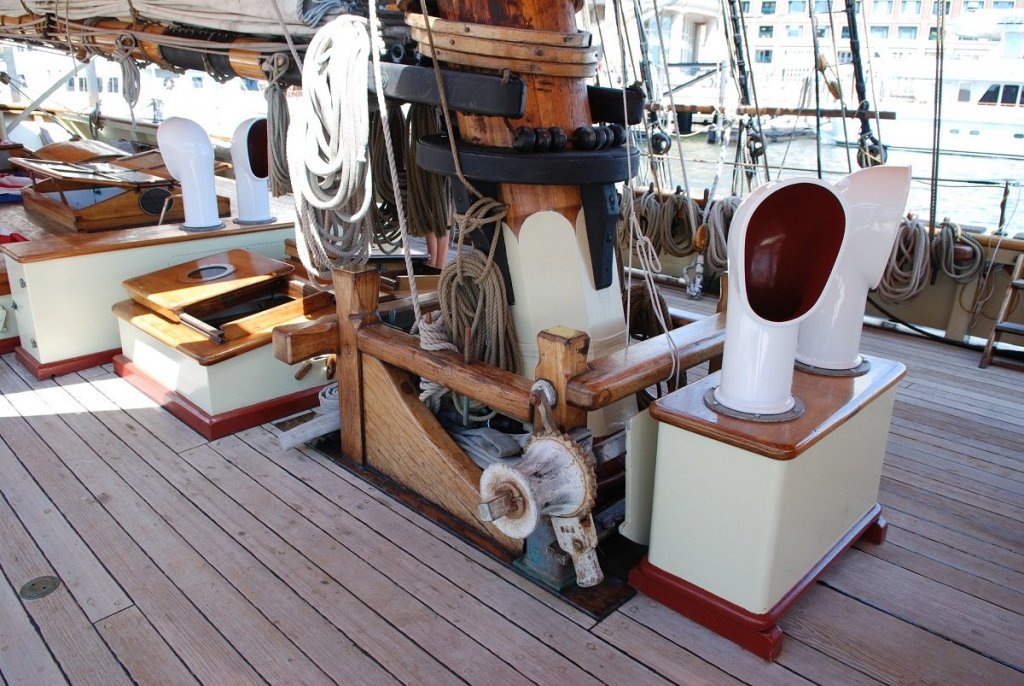
Oh, and those white cowlings were hand carved from pearwood, because the cast cowlings that came with the model looked horrible! I had some downtime at work and was working on carving them when one of the techs walked in and asked what I was doing. So I explained and showed him. He said, "Wow, that looks tedious!" I explained that it wasn't tedious if it was enjoyable!
-
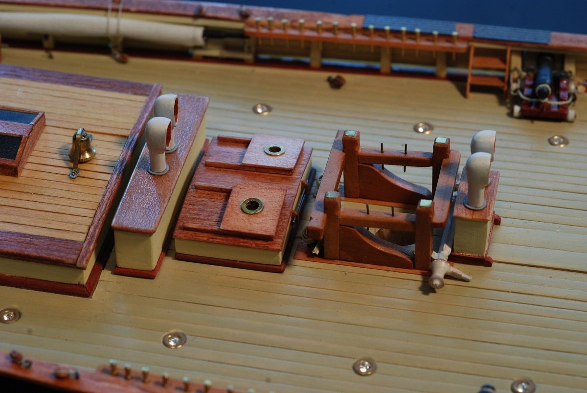
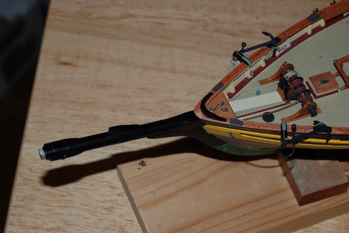
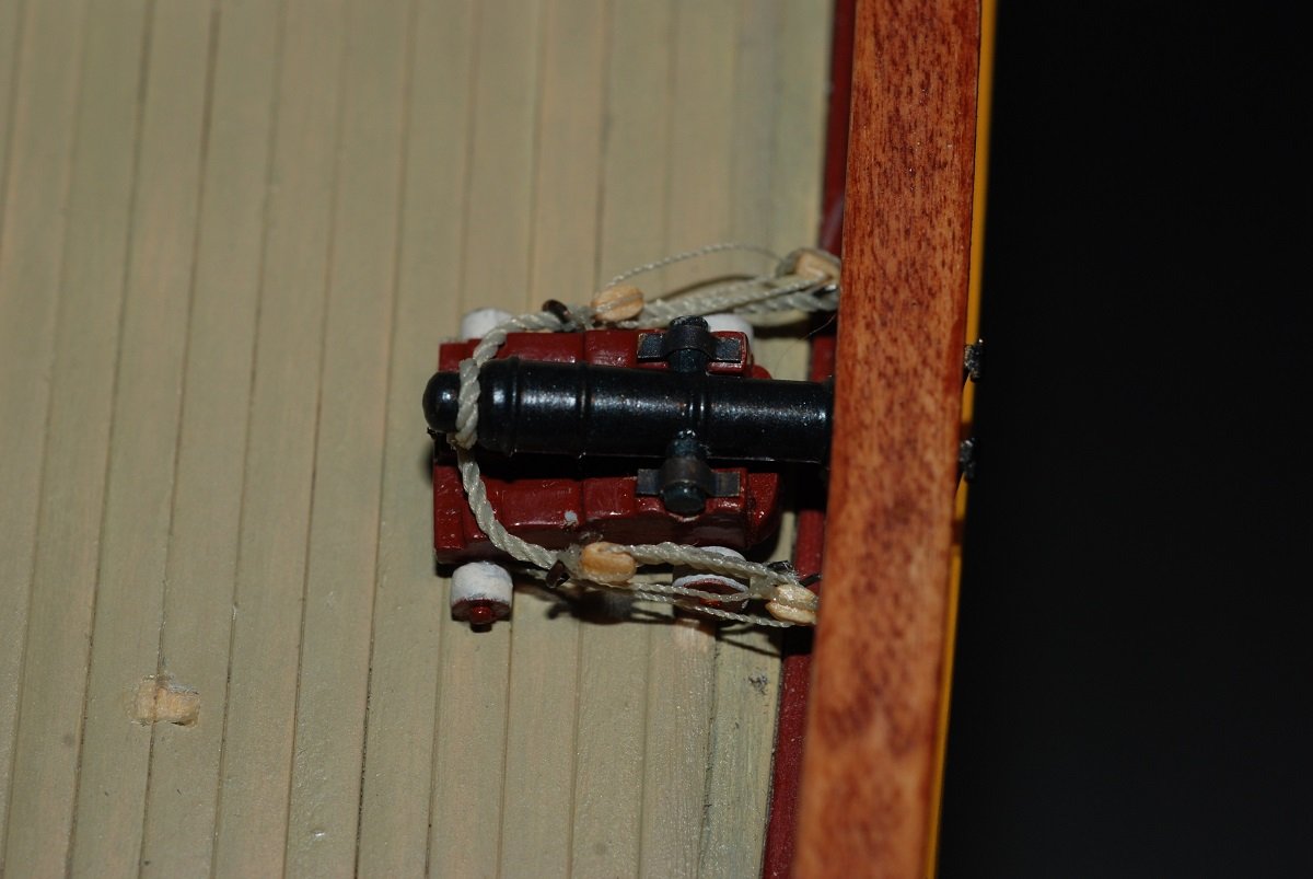
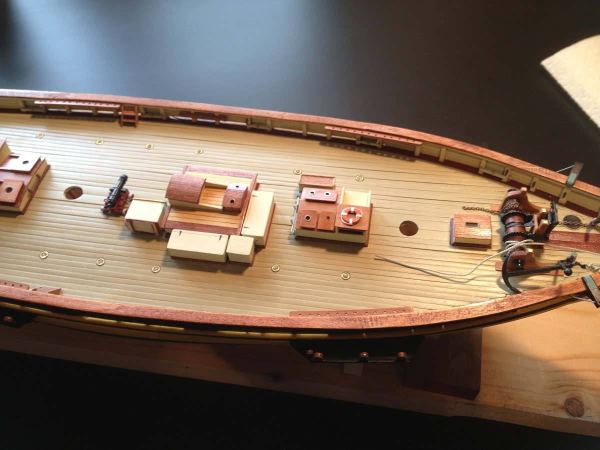
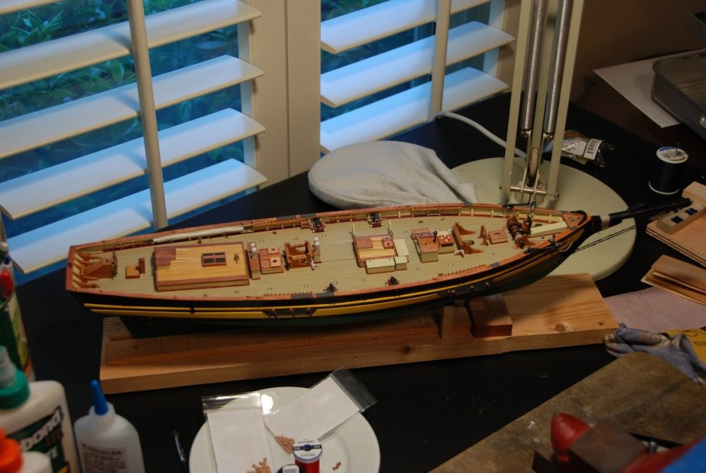
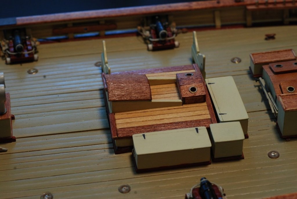
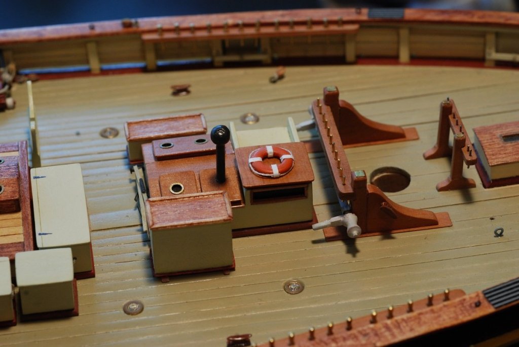
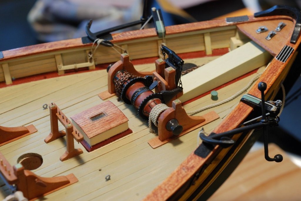
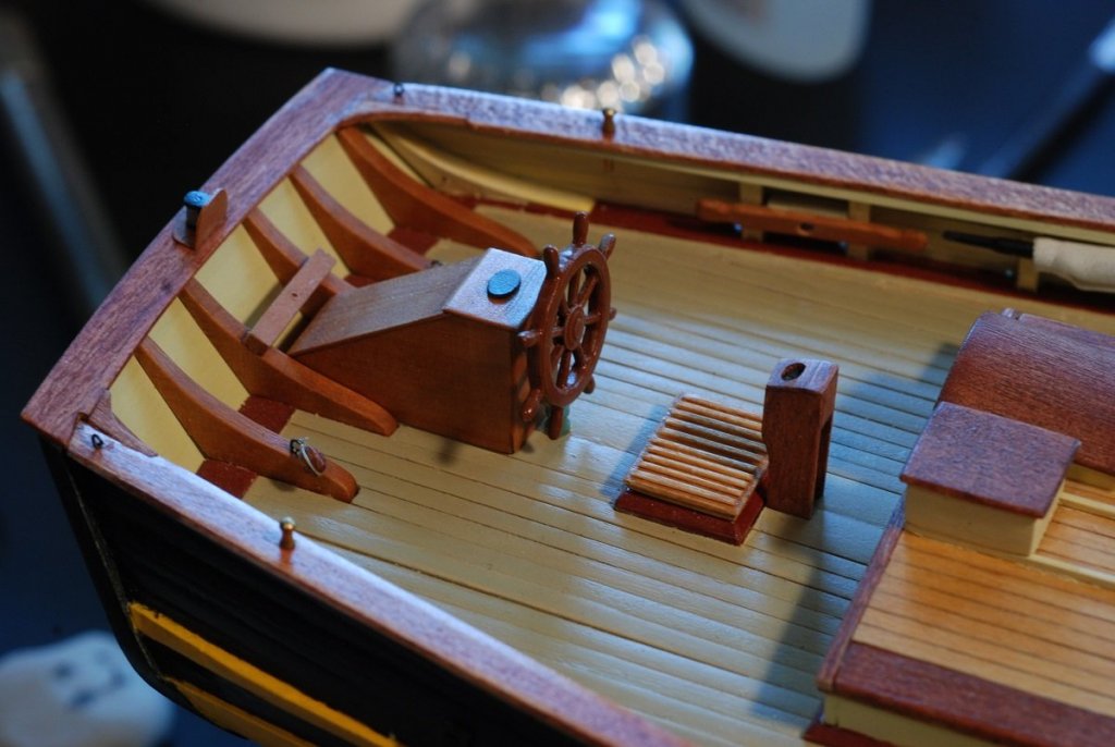
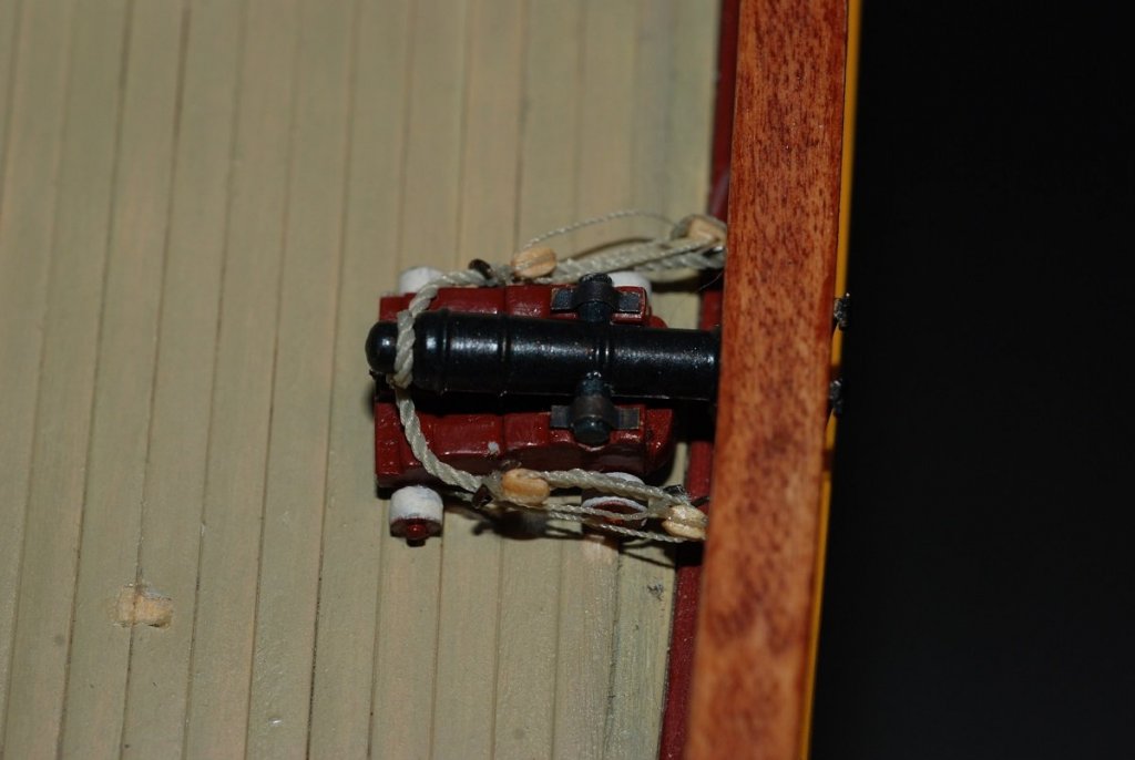
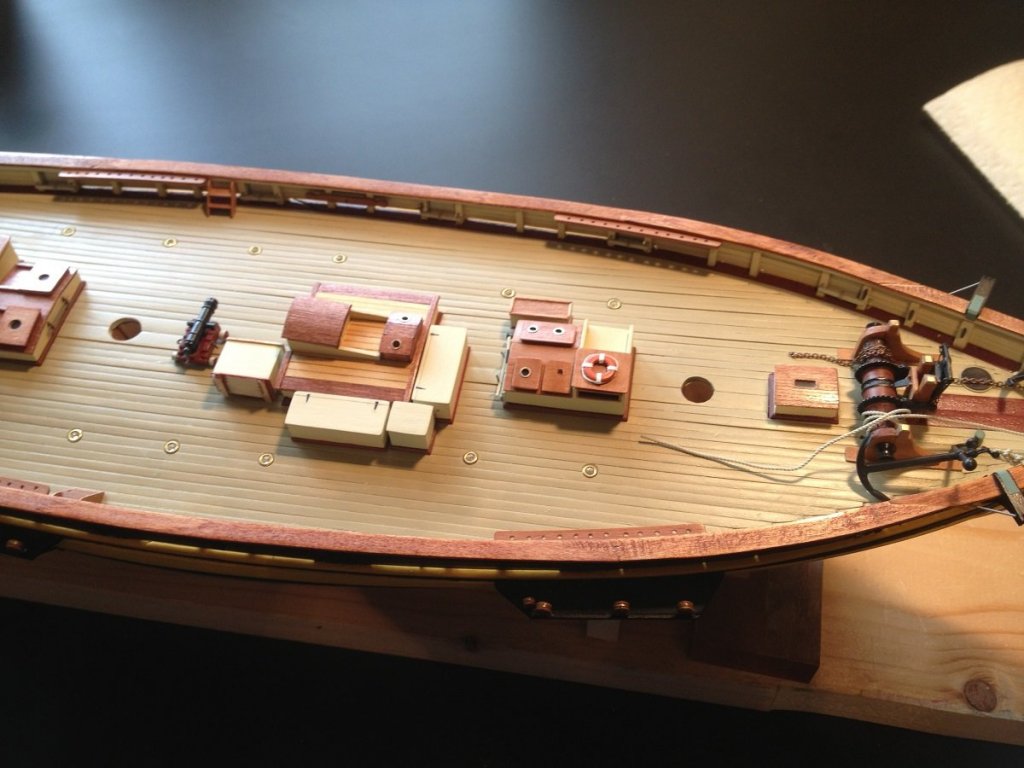
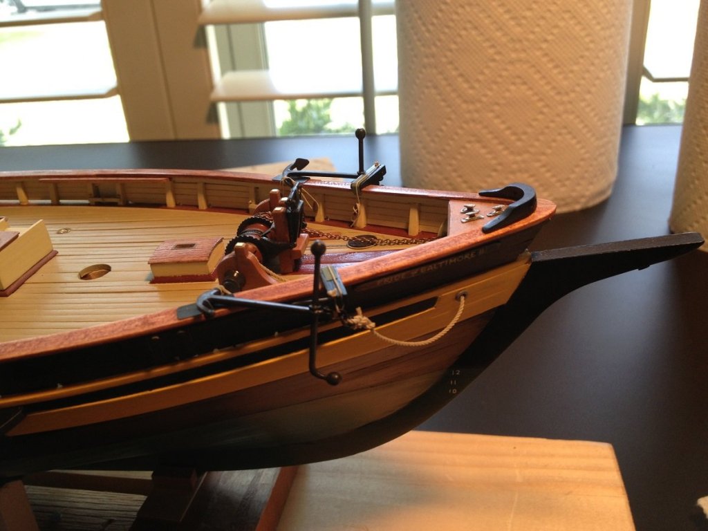
So it's currently April 2018. The following pictures show the status of the deck as of October 2015. The hinges on the deck boxes are small pieces of black decal cut into the shape of hinges. They bridge a little linear divot that was essentially scraped out of the wood using a graver-type tool. The anchor rope and chain have been installed. The ship's wheel was a part provided by the kit. I wasn't about to try to build my own. The cannon are rigged in place.


- 60 replies
-
- 7
-
-
- pride of baltimore ii
- Model Shipways
- (and 1 more)
-
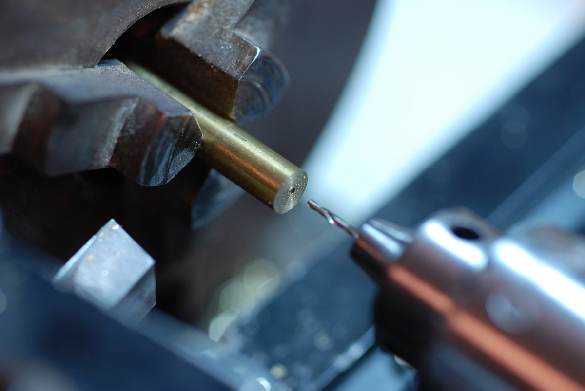
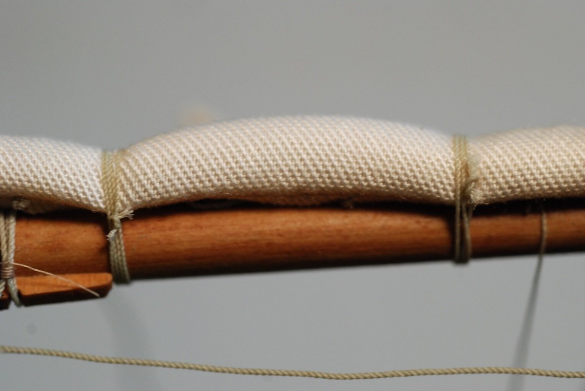
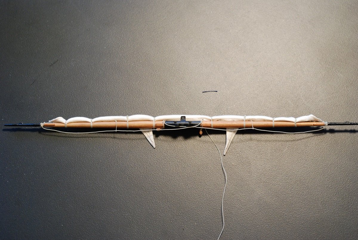
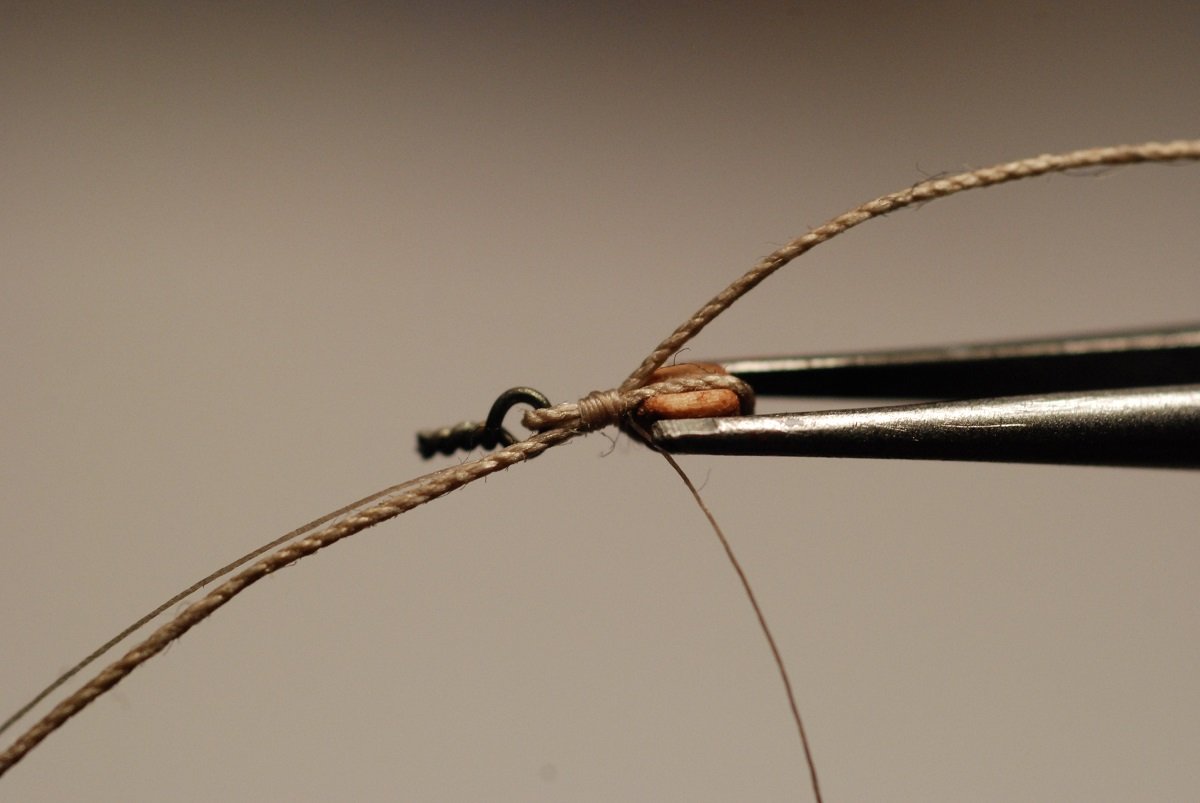
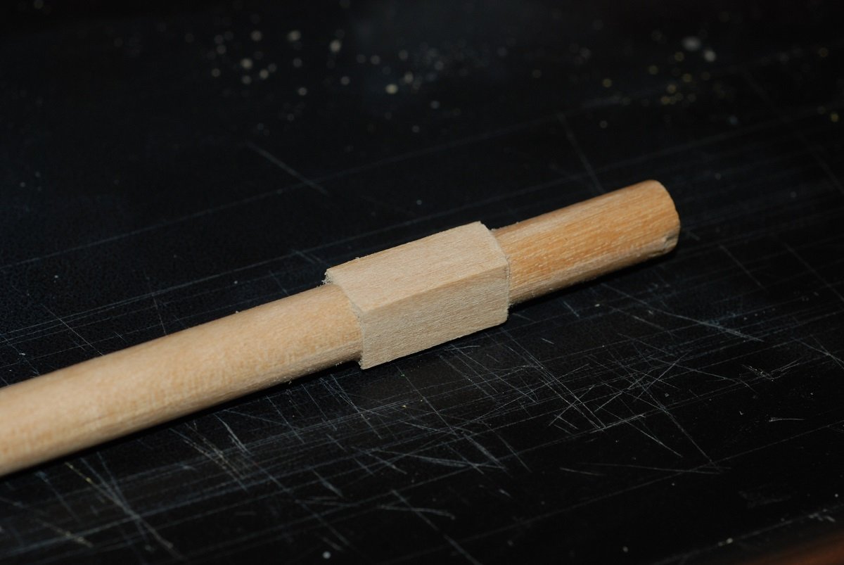
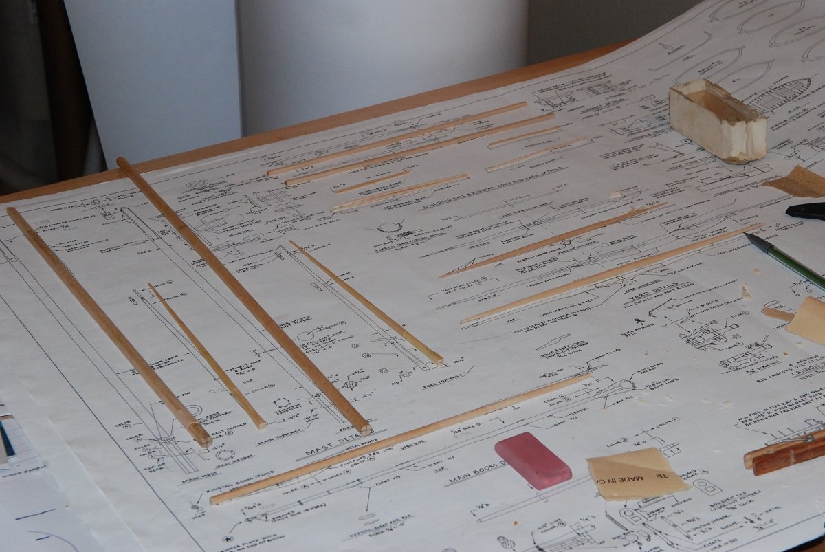
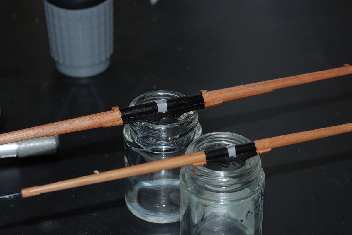
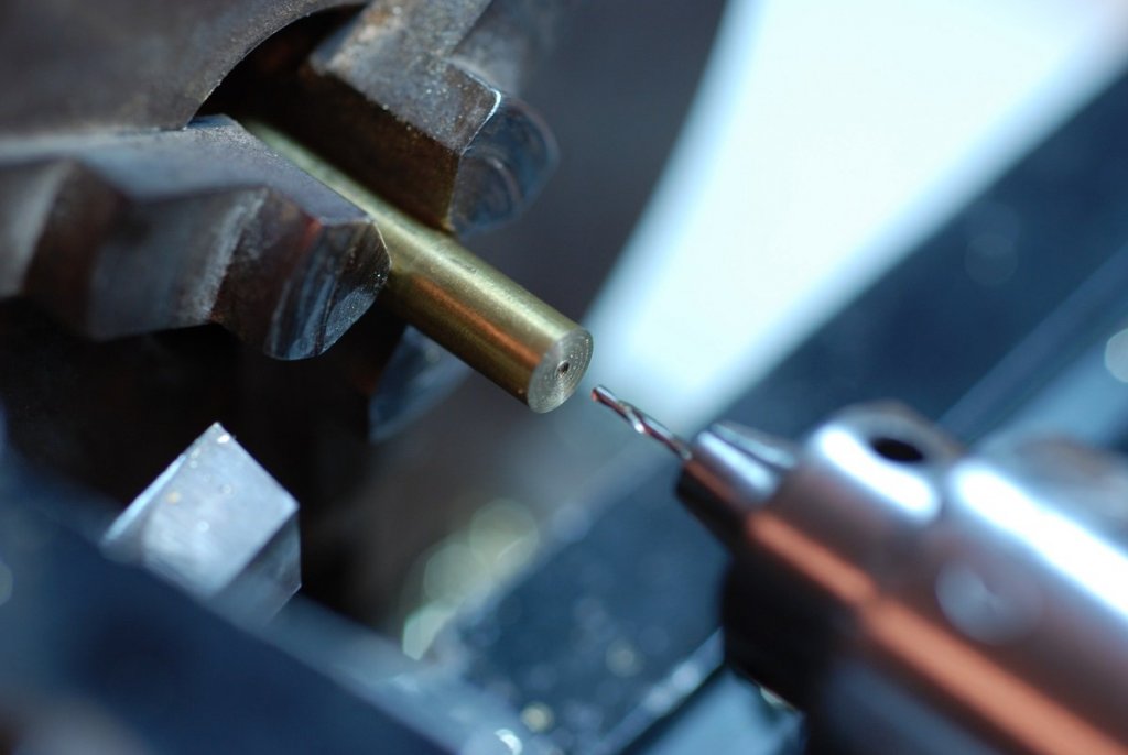
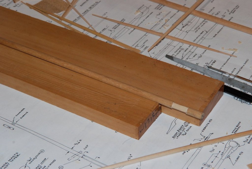
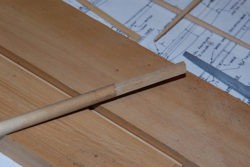
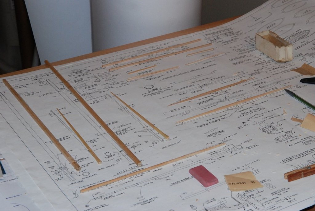
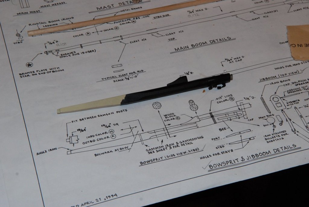
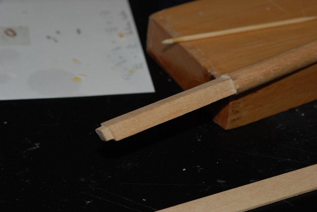
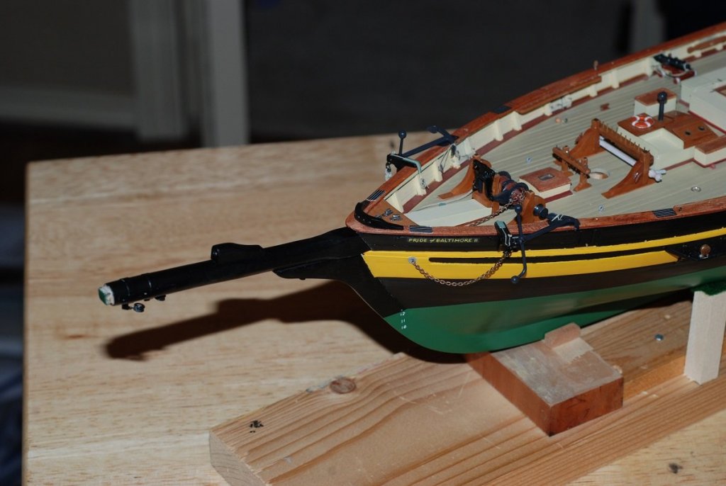
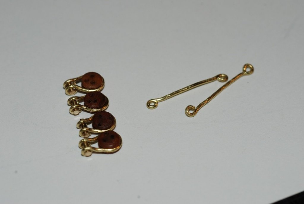
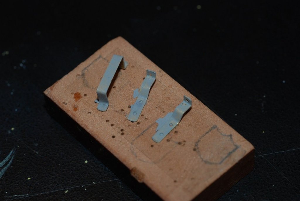
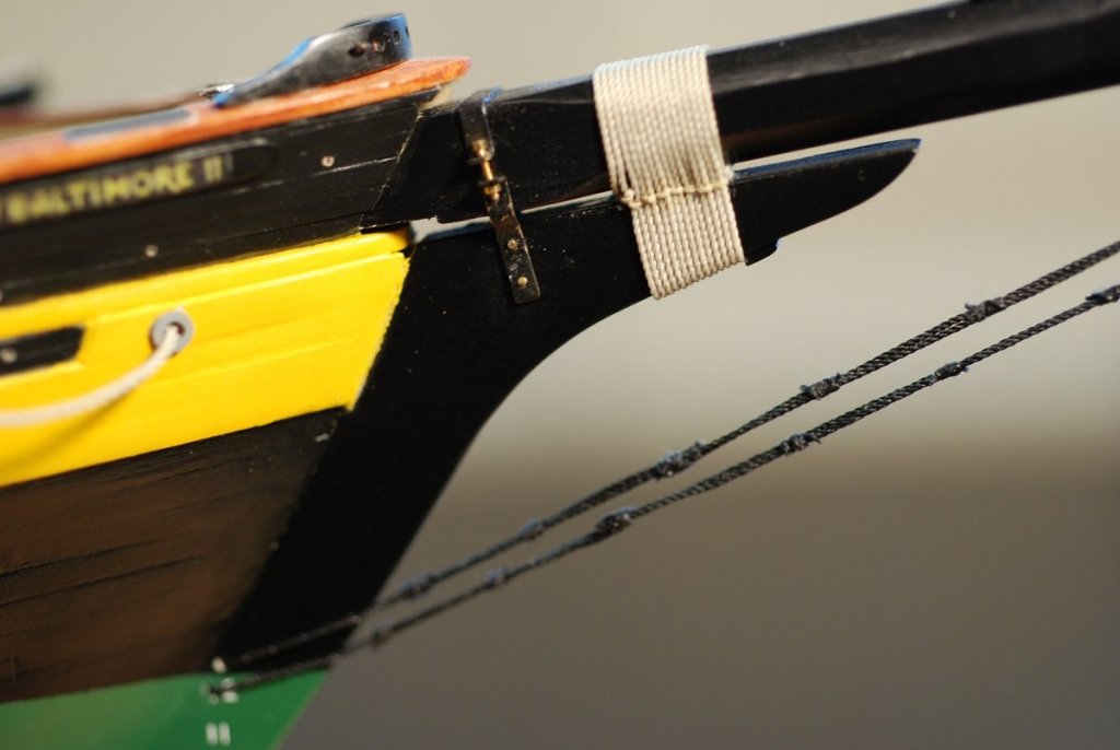
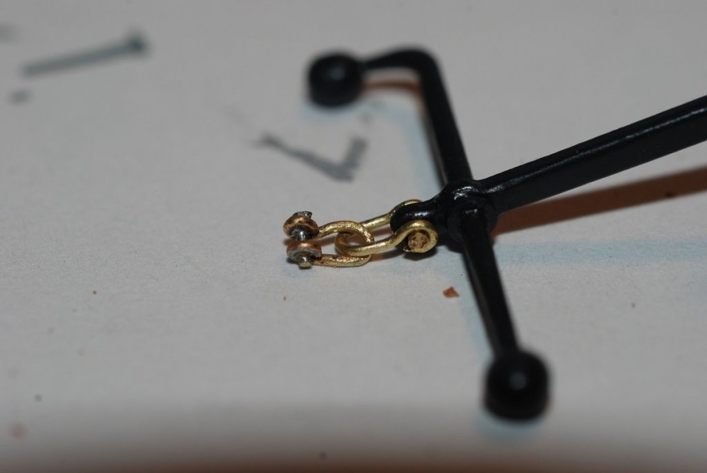
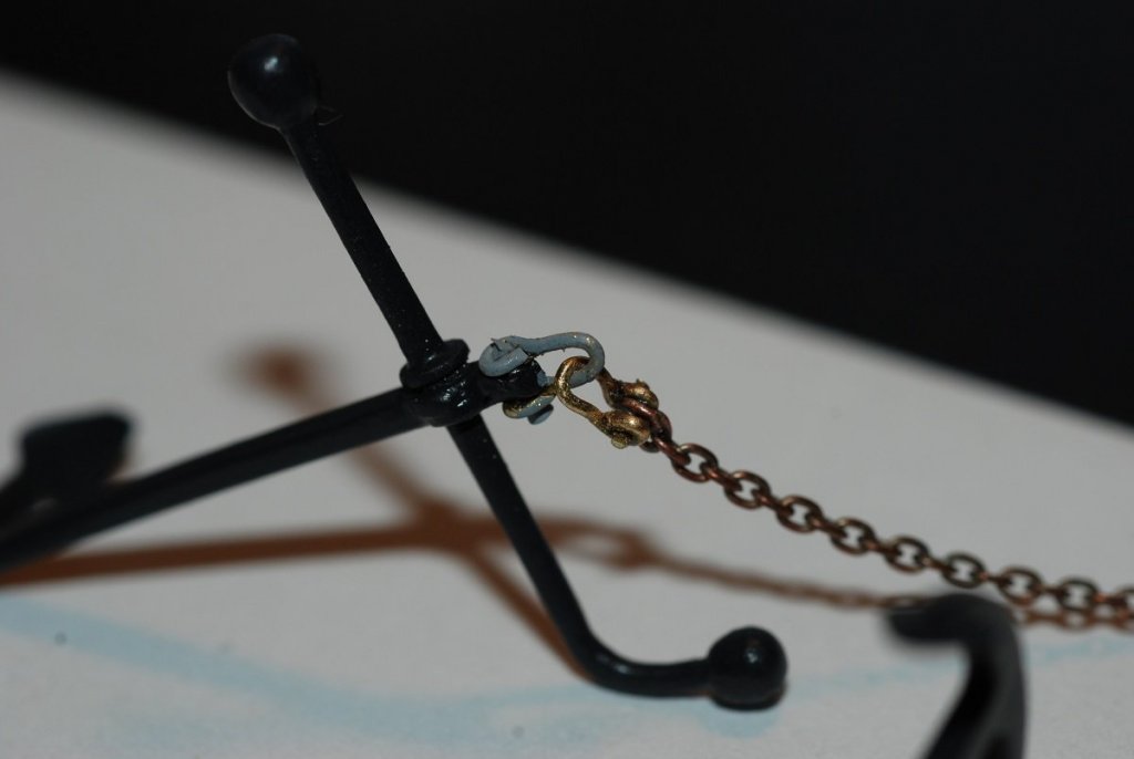
A long time earlier, I am not sure when, I tapered the dowels I would use for all the spars to their proper dimensions. This was done by hand, well before I ever had a lathe, using coarse sandpaper and elbow grease. Now, though, it’s time to work on the base of the masts where they take on an octagonal configuration, and the mast tops where they take on a square configuration. I used the pieces of wood above to serve as a groove to hold the mast steady while making shallow cuts into the base, then I used a file to create four flat faces. I did the same for the mast tops. These areas at the bases of the masts were then built up with pieces of flat wood to increase the cross sectional size of the flat faces. The protruding corners were then carefully shaved off with a razor blade to yield an octagonal cross section. Do I have a picture of the finished product? Of course not! The octagonal portion was painted a cream color that matched the color of the inside of the bulwarks, and the rest of the mast was stained and coated with topcoat. A picture of all the various spars on their places in the plans. The bowsprit was painted cream for the inboard portion, then the outboard portion was painted black. The metal rings to which the hearts are attached are already installed. Tenons were cut in the mast tops as well as the tip of the bowsprit. The bowsprit is now in place, with its base inserting into the Samson post. This is a picture of the deadeyes that are installed on the outboard surface of the bow. They rig to the standing rigging such as the forestays for the foremast and the bowsprit guys. Trial and error was again involved in figuring out how long of a segment of wire I needed to properly strop each deadeye. But it’s pretty satisfying work. A segment of thick wire is threaded through the loops of the stropping, and the end is peened to keep it in place. How to start the bowsprit gammoning? Here is how I did it. These are flat strips of brass that will be used for the gammoning irons. Holes have been drilled for wires that will pin the two lower plates to the stem. Harder to see are the holes that have been drilled to accommodate very small bolts that will join the lower plates to the single upper plate. Thanks to Scale Hardware for manufacturing such exquisite small bolts and nuts that were a perfect fit! They even had a little wrench to hold the incredibly small nut as you thread it onto the bolt. The yards have been stained, and the central part and the tips have been painted black. Metal bands have been placed on each; they currently have a coating of primer on them but will also be painted black. This picture reminds me that I didn’t do a good job of documenting the process of building the trestletrees for the foremast or mainmast. This part has turned out ok; the lanyard is threaded around several times and then is seized to itself with the smallest thread I had prior to discovering fly-tying line. I was unhappy with how this turned out. The bobstay is composed of a line that threads through the stem and is doubled up on itself as it travels from the stem to the bowsprit. This doubled line is shown on the plans as having seizings along its length. These seizings look very rough and stubbly. I will come up with a better plan for this area on a subsequent post.


- 60 replies
-
- 4
-
-
- pride of baltimore ii
- Model Shipways
- (and 1 more)
-
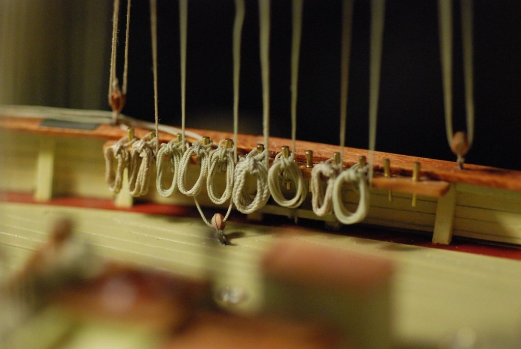
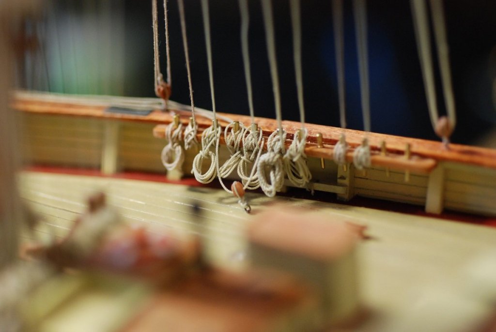
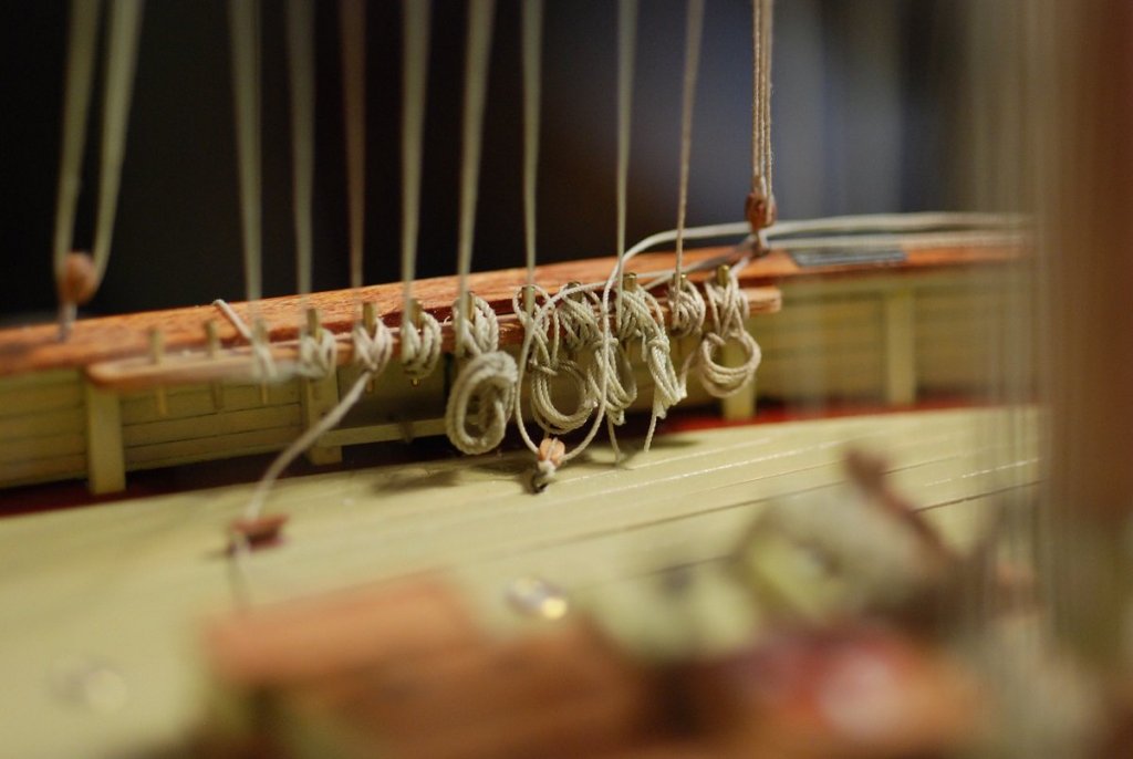
Turns out that a lot of the improvement is due to a change in the way I make the rope coils. Hard to describe; better learned by just doing. But I essentially wrap the coil with two wraps of line at the "top" of the coil. Then I used a small needle to open up those wraps, and one of the tails was passed through the space created by the needle. This created a loop at the top of the coil that could be adjusted depending on the needs of a particular spot on the pinrail. Once that was determined, the loop was fixed within the wraps with glue, and the tails were trimmed. The other part of the improvement came with following the suggestion above (thanks David) of placing a dot of CA glue (which I also try to avoid) on the underlying wraps of line on the pinrail, then placing the loop on the pinrail so the dot of CA secures the coil to the underlying wraps. I also would sometimes use a block of wood on the deck to force the coil up against the pinrail so it wouldn't be inclined to lean out in an unnatural fashion.
-
Aaahhh, much better...
- 14 replies
-
- 13
-
-
Nice pic, Spyglass! Ugh, I still have work to do to get them to look like that...
-
Thanks for all the replies so far. Meddo, here is a picture of my jig, which fits what you are describing: Frankie, I am going to play with your idea of using scrap line to tie a coil to the pin. David, I too try to keep away from CA but I am finding its use important in cases like this. I agree that using a different shape of coil may be helpful. More recently I have been able to make the coils less round and more long by strapping the coil temporarily with thread and painting it with dilute glue, then removing the binding thread. Two of the larger coils of line in the pictures were shaped in this way.

-
I am having trouble getting my coils of line to sit on the pinrails in a realistic fashion. I use a jig to create the coils and leave a loop of line that will wrap around the top of each belaying pin. I even use the jig to try to stiffen that loop in a way that will fall around the pin so that the coil then dangles under the pinrail. But the stiffness of the lines causes each coil to lean out away from the pinrail in an unrealistic manner. Some of these coils hang ok, but most don't fall like they would under the influence of gravity. Any suggestions?
-
I have had good luck serving my stays and shrouds with fly-tying thread. No fuzz.
- 525 replies
-
- 1
-
-
- anchor hoy
- hoy
- (and 1 more)
-
Are you happy with the "fuzz-free" nature of the Aurifil thread? I am always looking for ideas when it comes to thread.
- 525 replies
-
- 1
-
-
- anchor hoy
- hoy
- (and 1 more)
-
Nice build log! It's good to see such quality building going on close to where I am (Dallas)!
- 525 replies
-
- 2
-
-
- anchor hoy
- hoy
- (and 1 more)
-
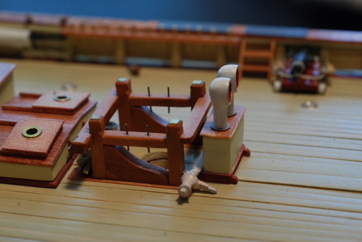
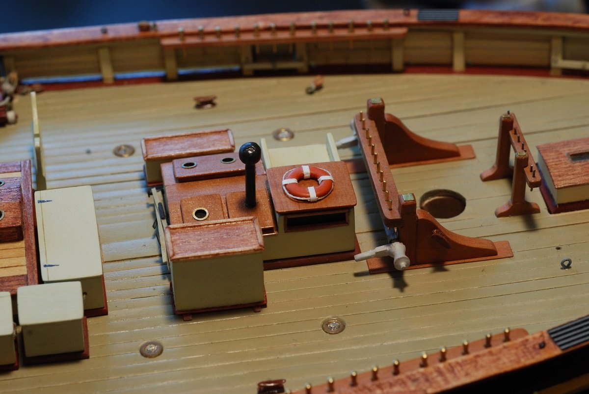
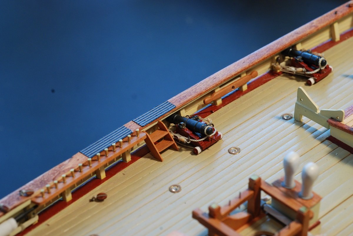
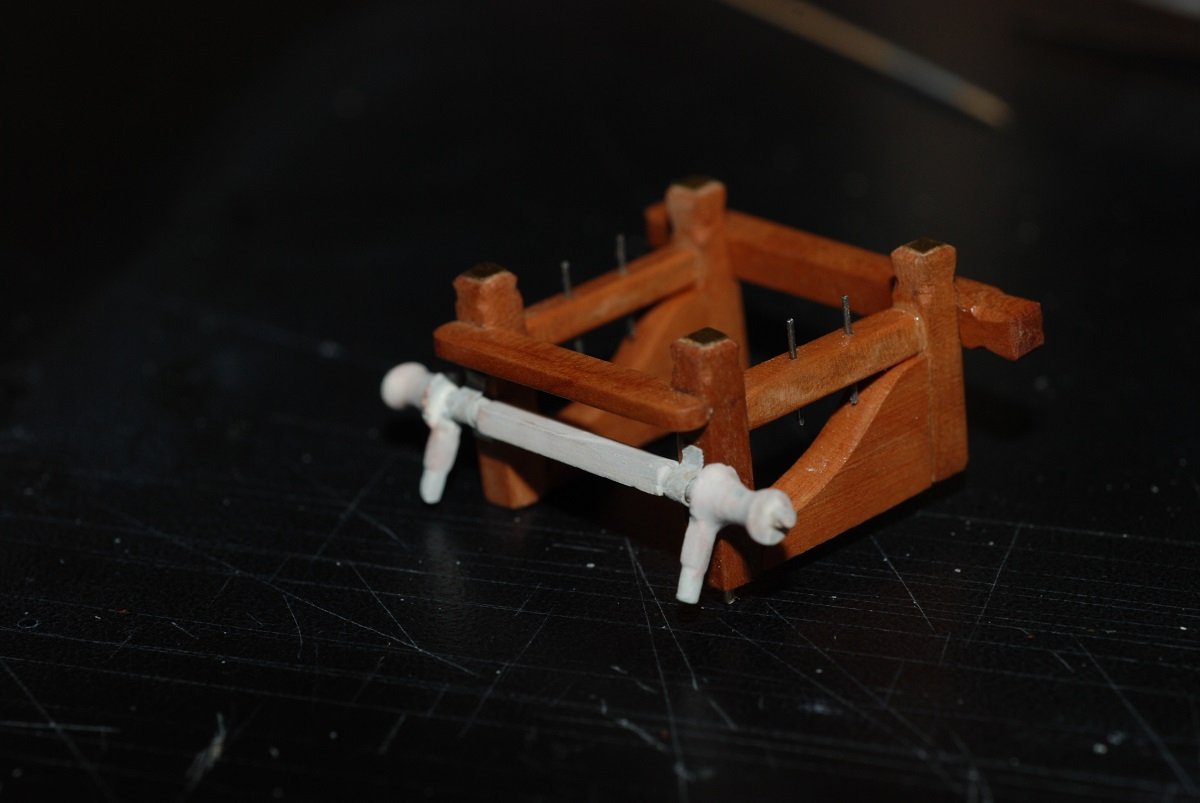
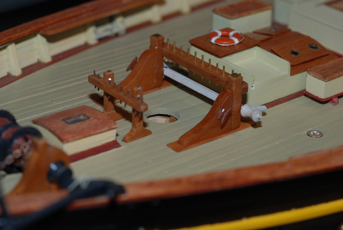
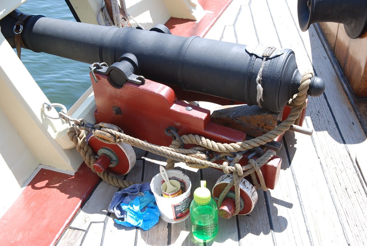
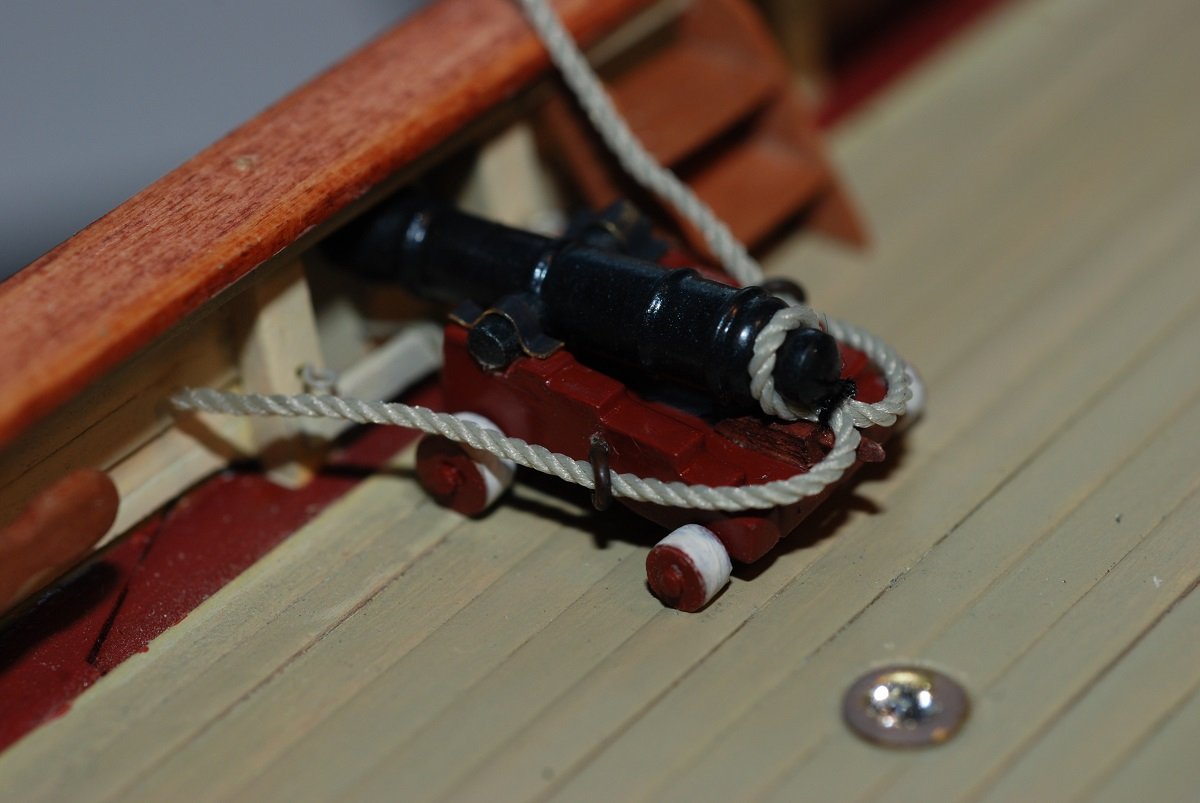
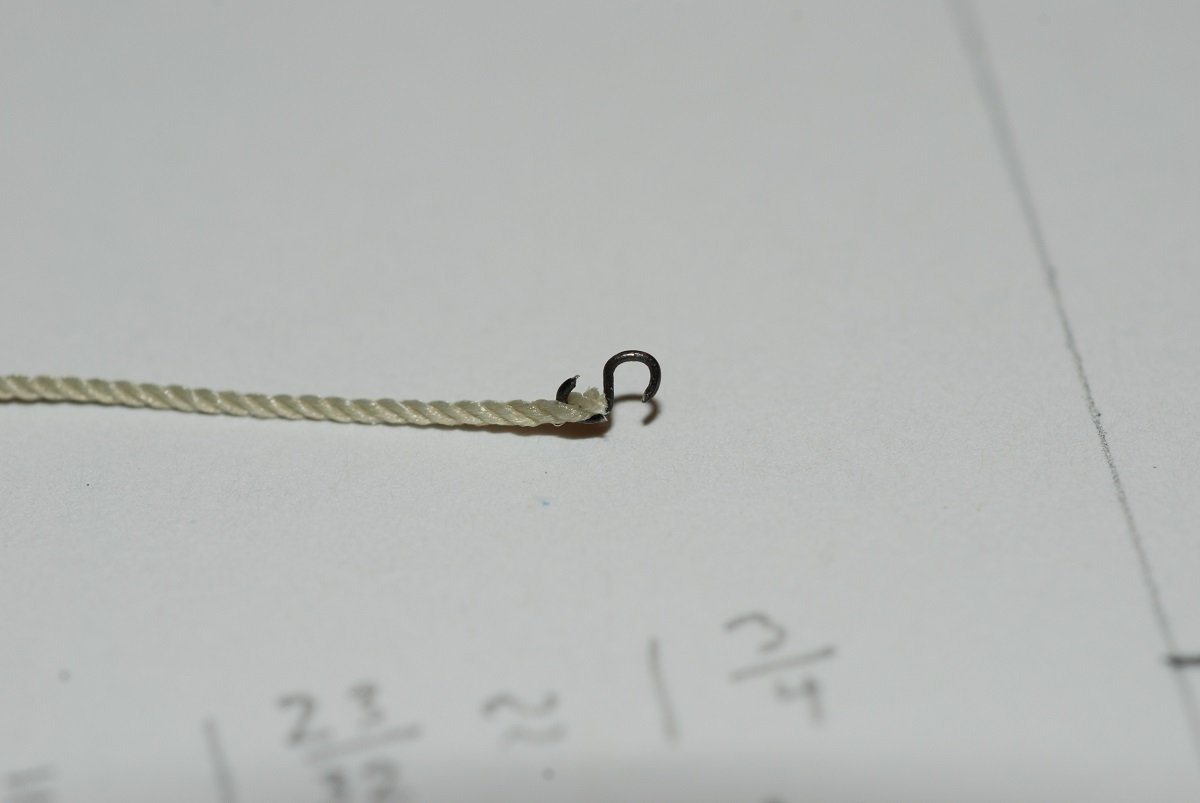
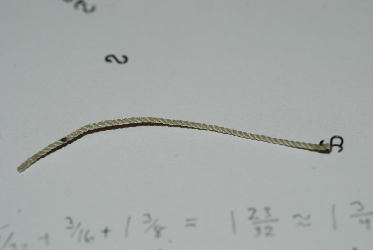
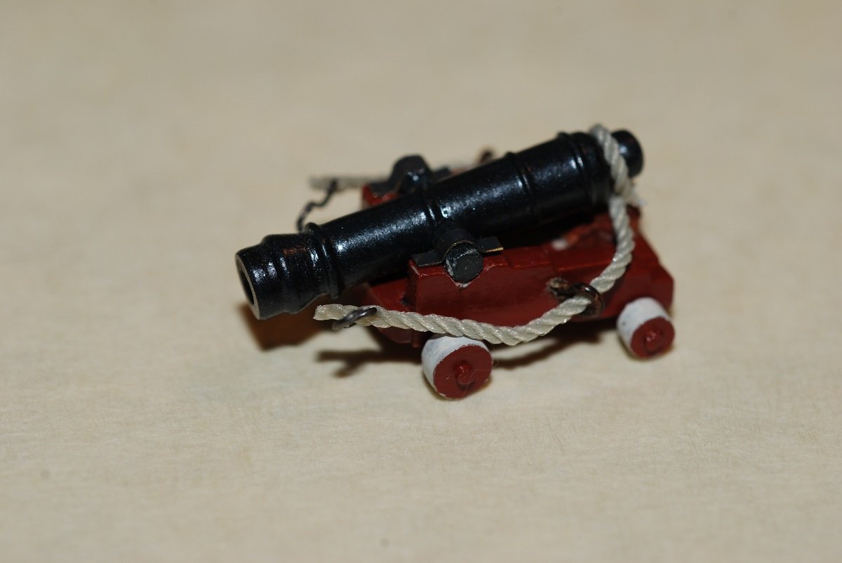
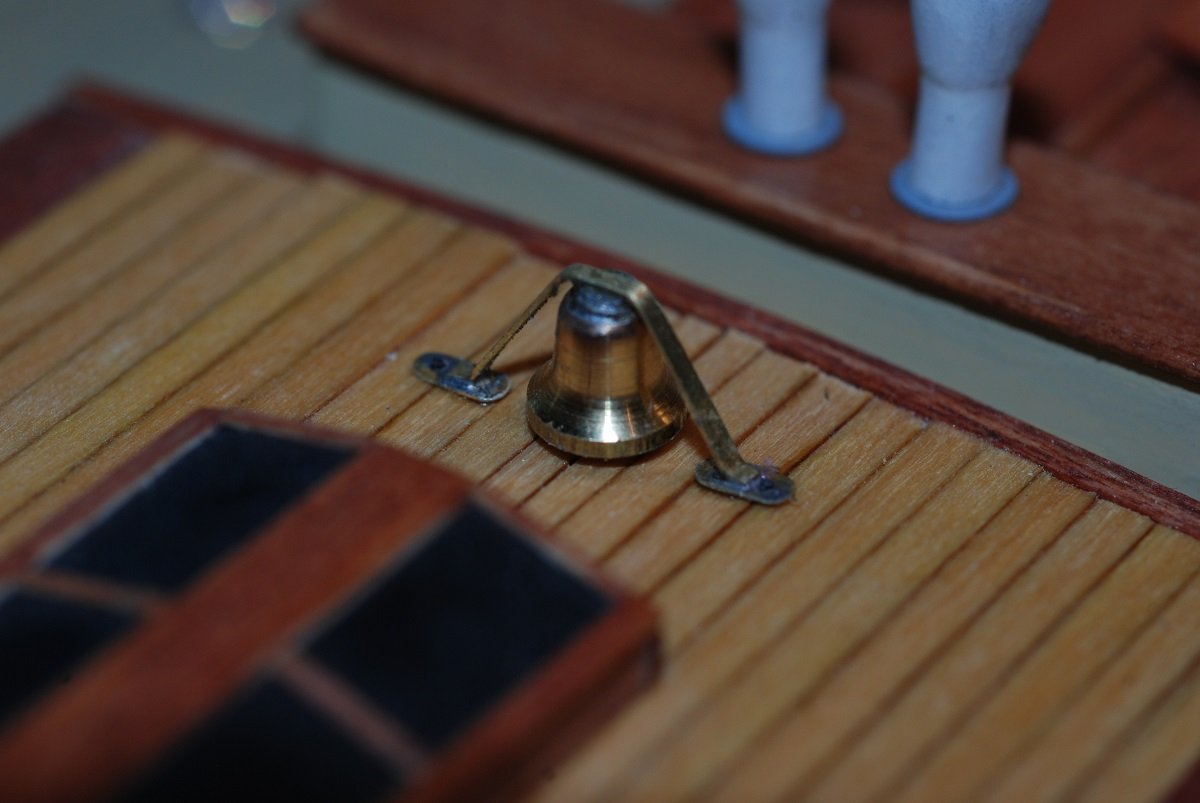
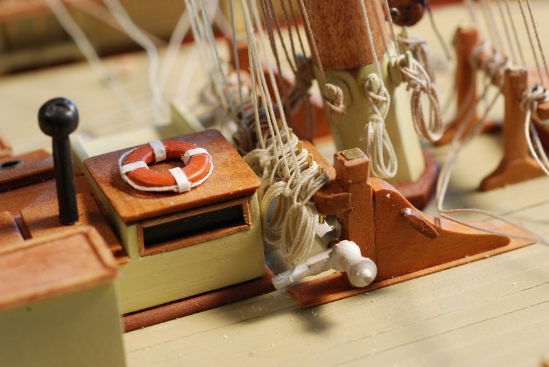
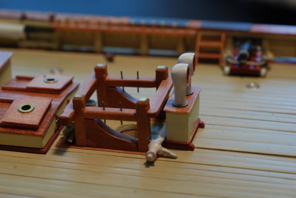
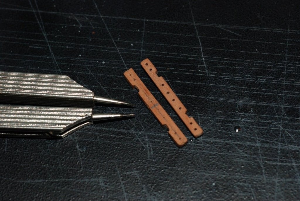
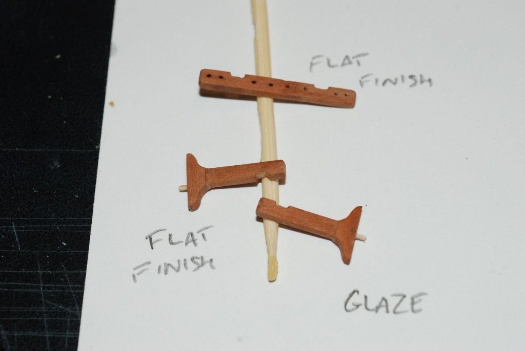
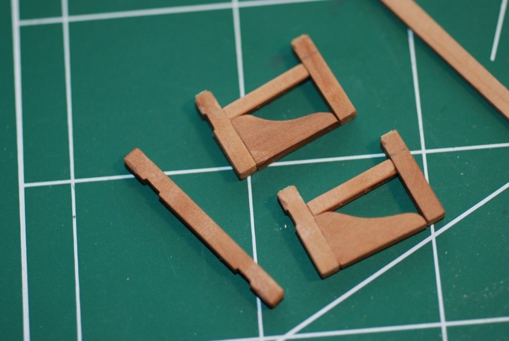
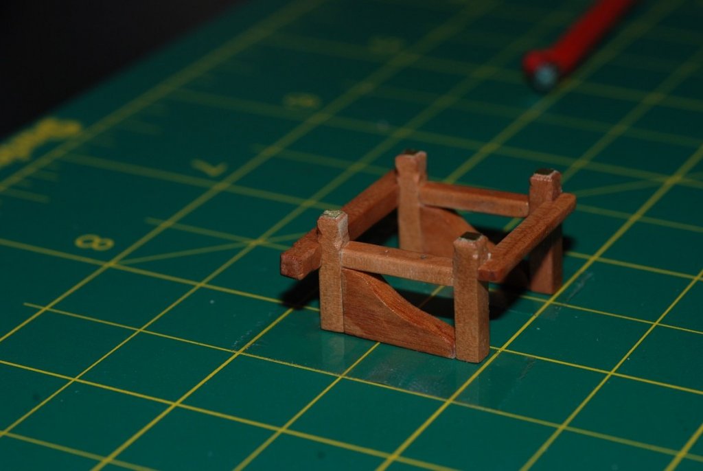
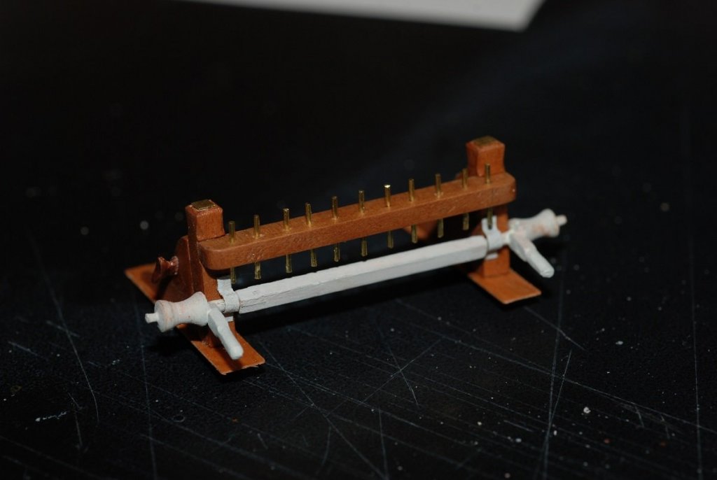
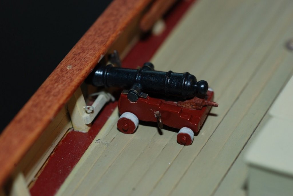
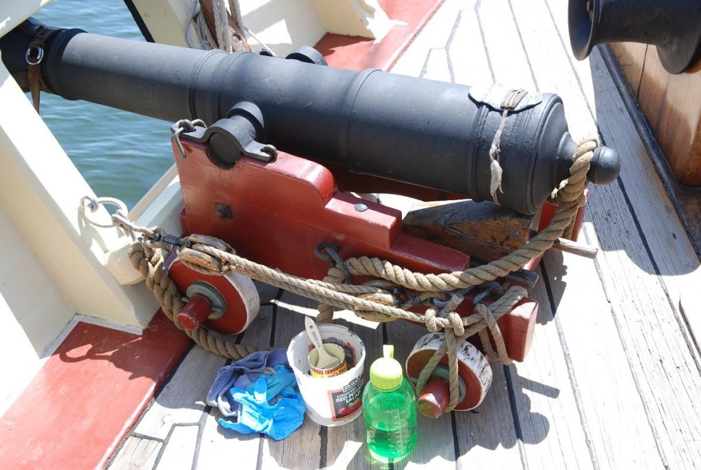
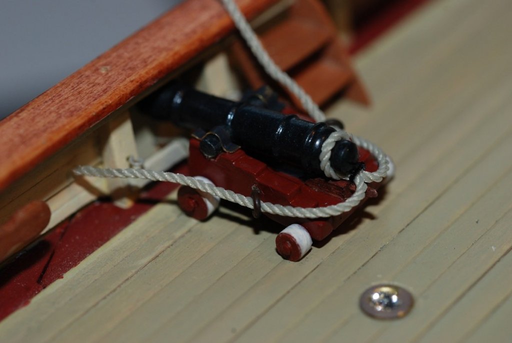
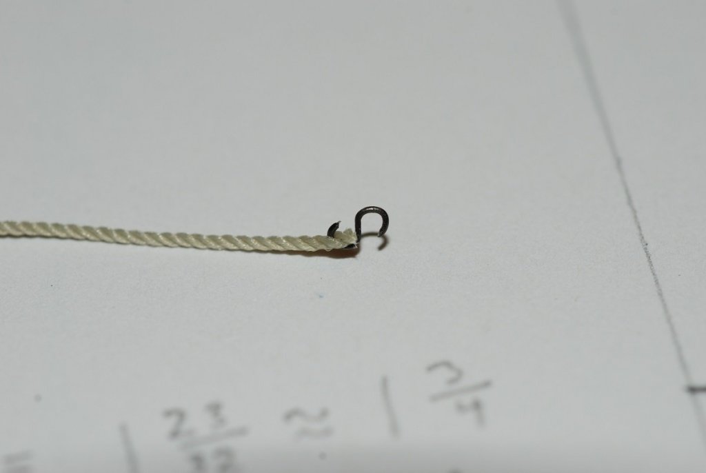
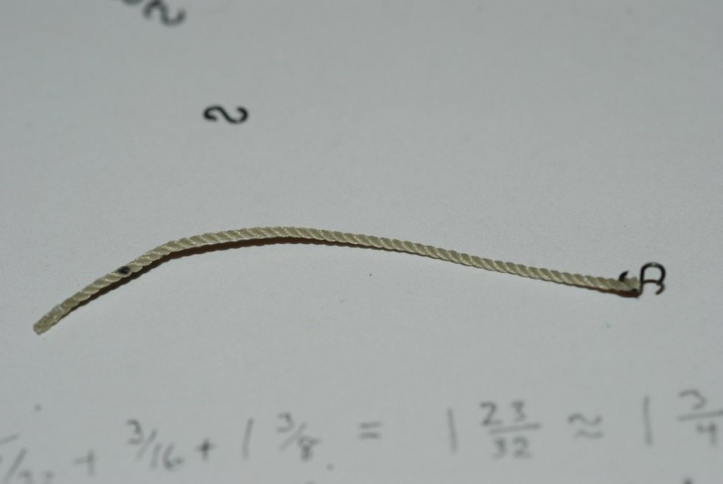
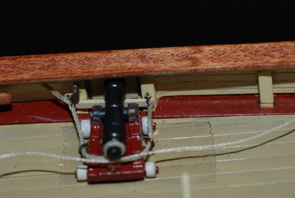
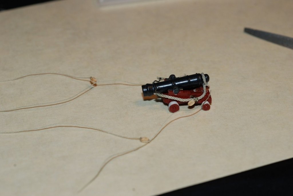
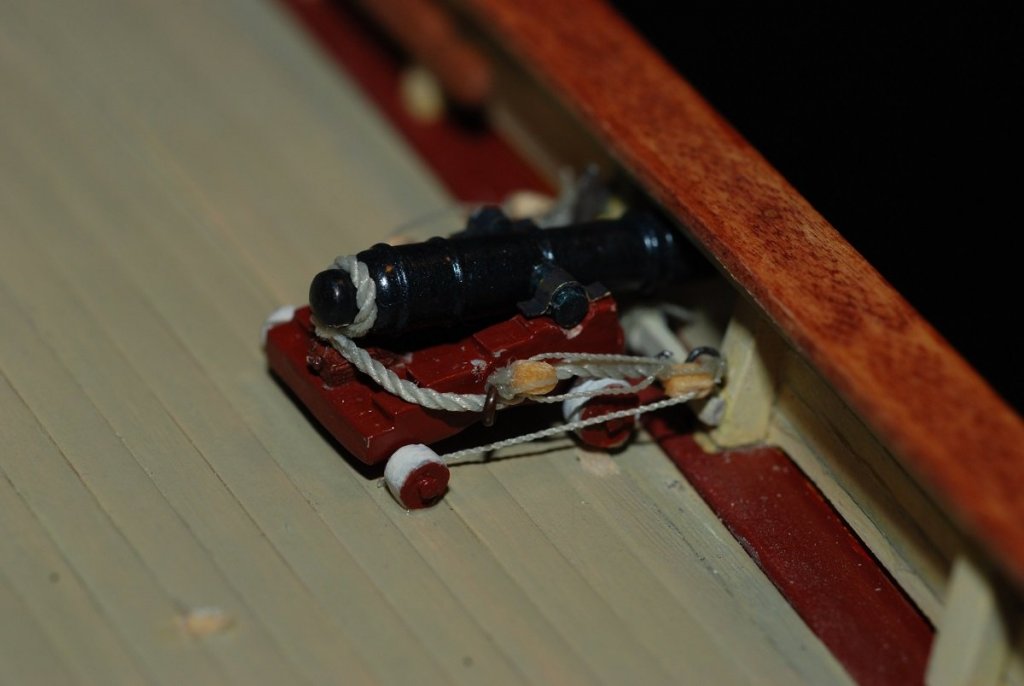
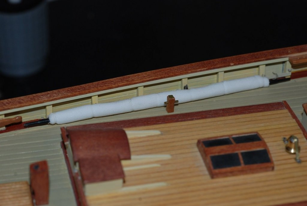
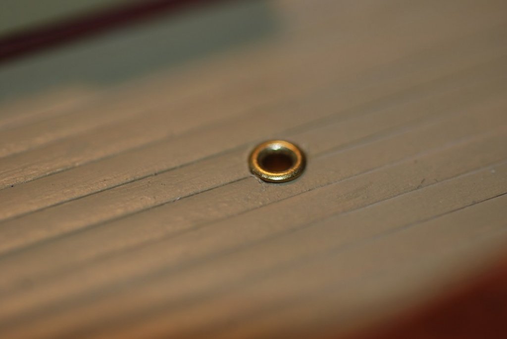
Next up are the various pin rails that are set up around the base of each mast. These are the pin rails just forward of the foremast, which handle the fore topsail control lines. This is more pearwood. The pins themselves are segments of 0.014” wire. I was playing with various finishes that I had handy at the time; sadly, all my Floquil glazes and flat finishes have now congealed and are no longer useable. I am back to using Testors Dullcote lacquer for jobs like this. This apparatus surrounds the base of the main mast and is made of pearwood. Here it is all assembled, and the chamfers have been added. Small bits of brass sheet have been applied to the top of each post. There is a small windlass along the forward edge of the mainmast pin rail. It was painted white with a touch of rust to emulate the appearance of the real thing: These are parts of the rail that sits just aft of the foremast. It also has a mini-windlass attached to it. Here is the area of the foremast with its pinrails installed. And the pinrail at the base of the mainmast. Time to work on the four cannon. The sleds are made with pre-cut parts from the kit. The cannon were also provided and required cleanup prior to blackening them. The quoins are the wedges under the back end of the cannon that adjust its tilt. Those were handmade and stained up. An image of the real thing gives you an idea of the rigging used to secure the cannon. A very large line runs from the cascabel at the butt of the cannon to rings at the bulwarks. A smaller line is used to rig the blocks on either side of the cannon sled. This took some trial and error. How do I take a pretty thick line and get it attached to these small eyebolts on the bulwarks? I suppose a purist would undo the weave of the line and create an eye for a hook. Too much work for me. I applied some CA to the end of the line, then created an S-hook that could be stuck through the strands where the CA began to peter out. Where to do that on the opposite end of the line, though? After inserting one hook, I assembled the rig with the one hook attached to its eyebolt, tied it to the cascabel, and ran the other end up to the area of the eyebolt. I marked that spot with marker and inserted a hook there, then applied CA beyond that point to solidify the line. The excess was then trimmed. This is an image taken before the excess is trimmed away (left side of the cannon). Double sided tape is being used to temporarily secure the cannon to make rigging easier. Now things are trimmed up. These are 2 mm blocks that have been secured with 0.004” line. One set of blocks is rigged to the ring on the side of the sled. The other set of blocks will be rigged to eyebolts on the bulwarks. I don’t remember anywhere else on the model where I used such small line. The line is rigged through the blocks and then tied off at the back wheels of the sled. Now I just have to do that 3 more times. After doing this, small amounts of glue were used to secure the back wheels to the surface of the deck. Through Billing, I was able to find a bell of reasonable scale to install on the aft cabintop. My soldering is getting better! The fore topgallant sail is stowed under the port rail. I wrapped a portion of “sailcloth” (a fine Egyptian cotton fabric) around the spar and wrapped it with ties. The spar is then secured using small hooks installed on the rail and on the bulwarks. I am slowly getting caught up to real time! These steps were done in 2013, and it is now January 2018.


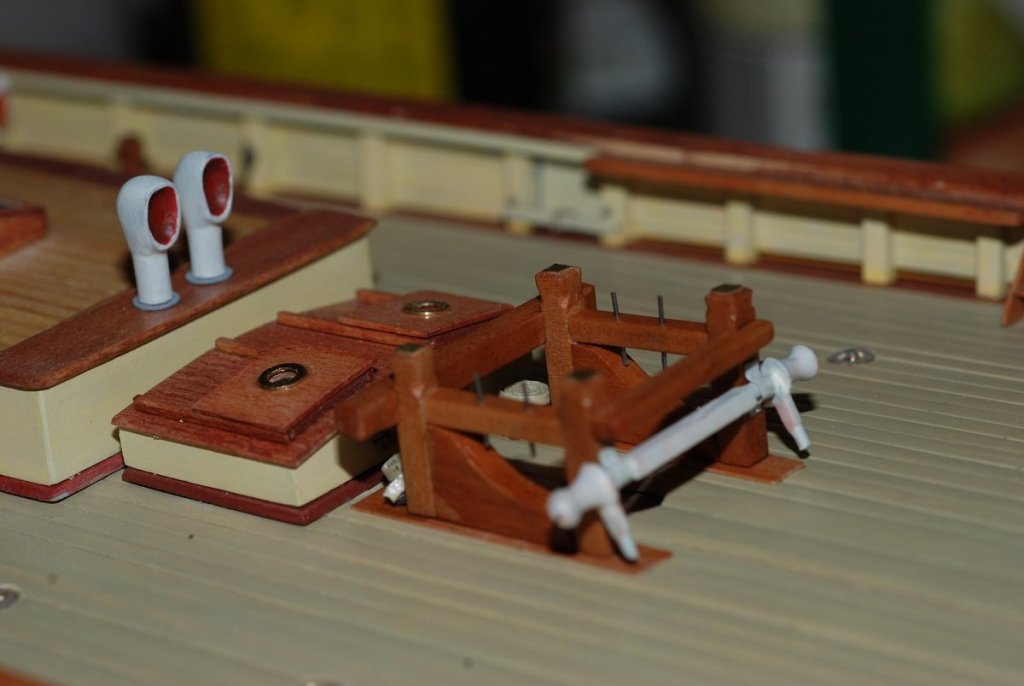


- 60 replies
-
- 4
-
-
- pride of baltimore ii
- Model Shipways
- (and 1 more)
-
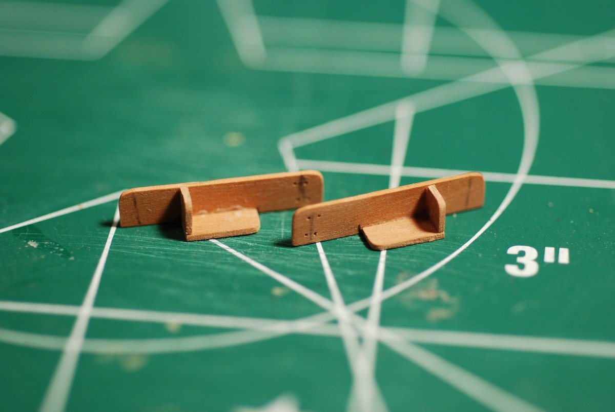
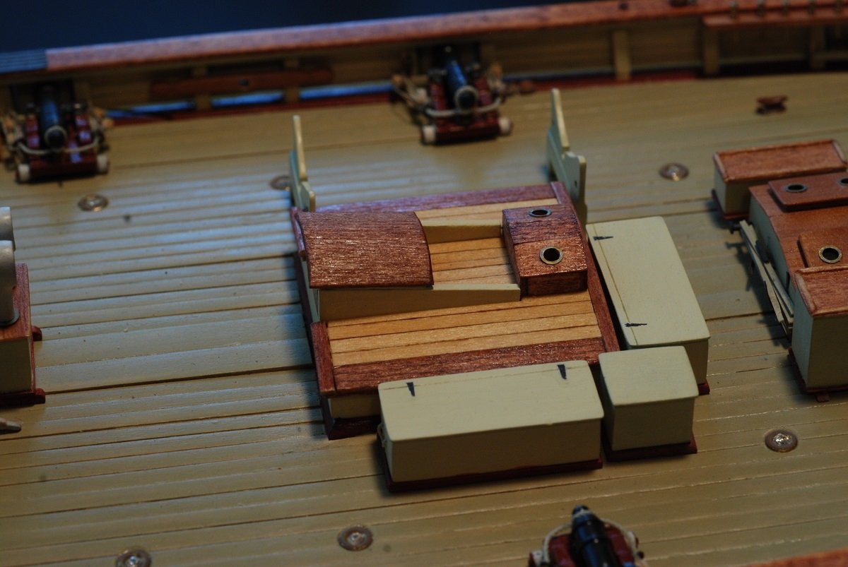
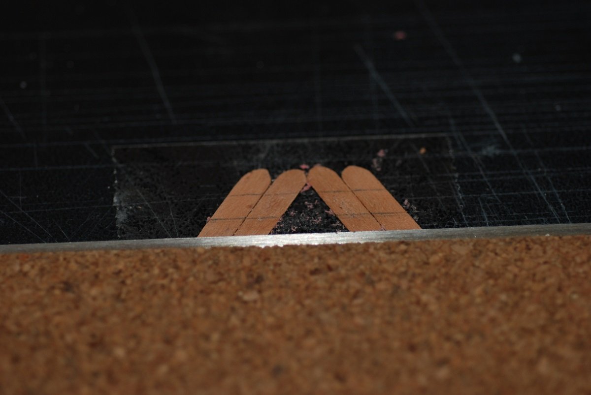
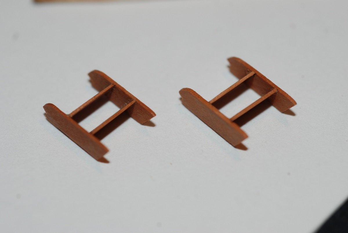
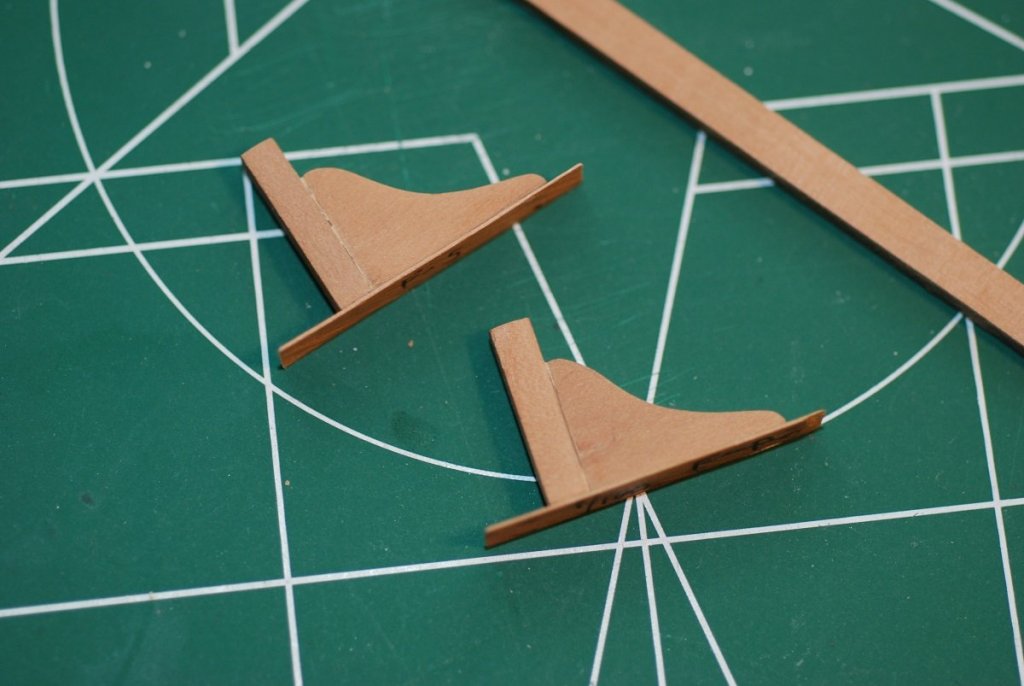
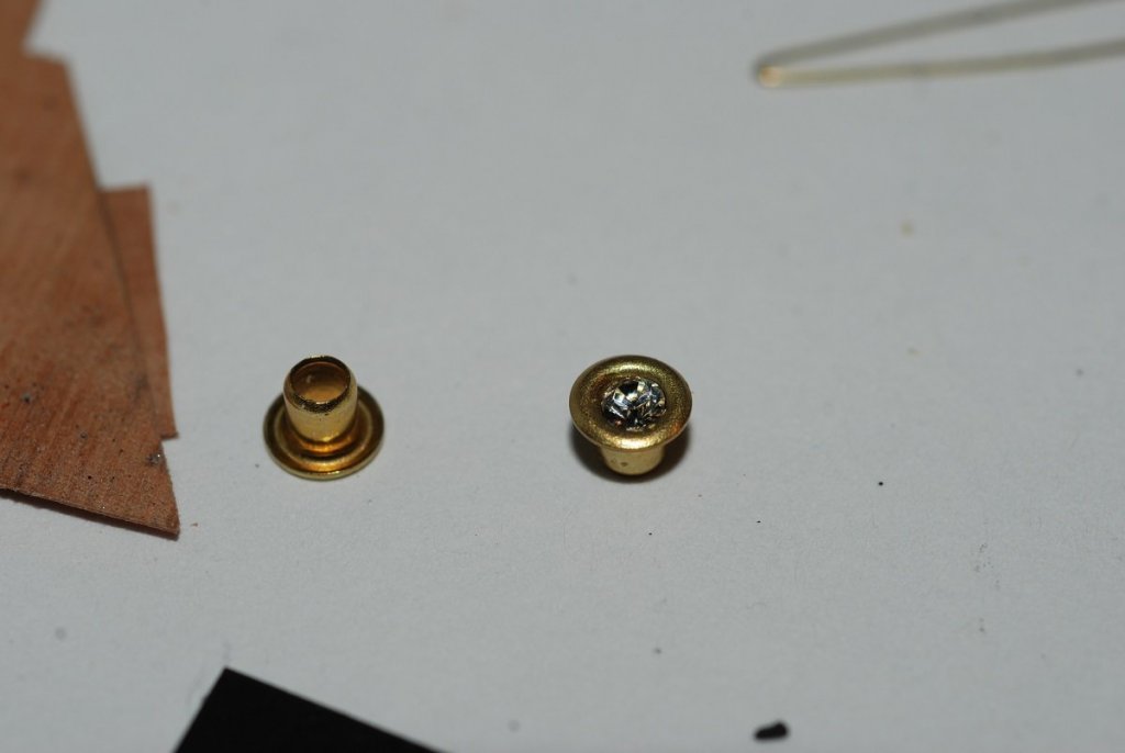
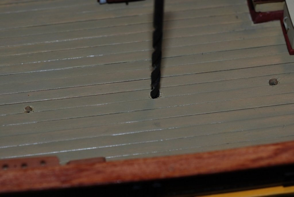
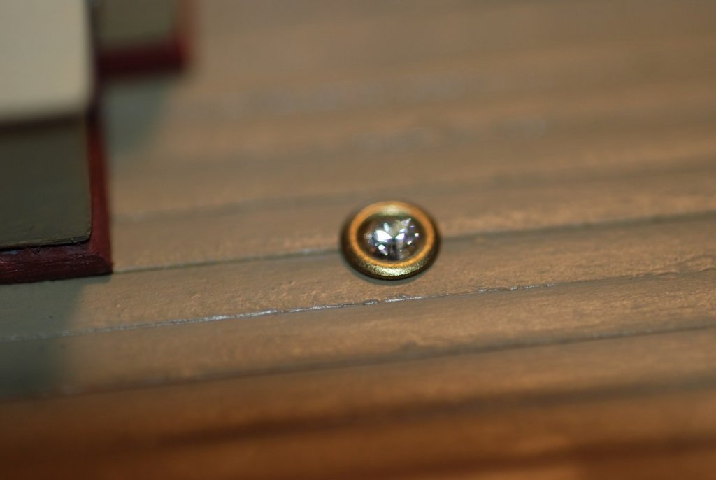
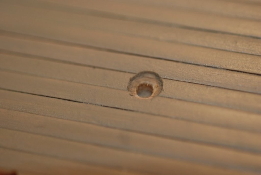
OK, back to work folks: Next step (ha ha) was the stepladders. These were built with pearwood sheets that were 1/32” thick. The first step was to fabricate symmetric pieces for the side rails. Two pieces were sandwiched with rubber cement and the shape was created. I found that by lining up these side rails on the bench top with their bottom edges aligned, I could mark off consistent positions for the joints for the steps: Grooves were very carefully sanded using a file in the area of the marks, to create landing points for the steps. Notches were then cut in the top part of the side rails to create a joint where the stepladders reached the rail. I love working with the fine-grained pearwood! Next detail are the deck prisms. The kit provides little gemstones and bushings for them to sit in. However, in looking at the real deal, the provided gemstones were too big. My local jeweler and I have a good relationship, though, and he gave me little rhinestones that sat perfectly within the bushings. Better choose the spot for drilling these holes carefully, because there’s no turning back if I position one wrong… This is how things look if I simply drop the bushing and jewel into the drilled hole. They sit proud of the deck, and they look a lot brassier than the real thing. So here I took a larger drill bit and did a countersunk hole that is of the diameter of the large flange of the bushing. That looks better. I also painted the brass rings a shade of green-gray that gave it a patina look. This picture shows the decklights in place, and also the fabricated pin rails, which I have no documentation of making. On the far right, I am starting to position one of the anchors and the port-side anchor chain. Also, I am starting to think about rigging cannon. Speaking of which, here is one of the anchors. After fabricating the shackles associated with the windlass, fabricating ones for the anchor were comparatively easier due to their larger size. When I was cleaning up the anchors provided with the kit, I was unhappy with how the stocks looked. As I recall, I was cleaning one, and I broke the stock while keeping the shank intact. So, I took some wood and fabricated a new one that could pass through a hole drilled in the head. The curved end of the stock was created by carefully attaching a spare piece of wood and (very) carefully carving the curved part of the stock out of it. The end balls were also carefully carved and attached. They are not quite spherical but I think they turned out ok. The chain was blackened and attached to the shackles, which were painted black. The starboard anchor is on rope; the port side anchor is on chain. Rail pads for the anchors were made out of painted styrene sheet. The anchor is secured by a line at the end of the cathead, and another is wrapped around the inboard fluke.

- 60 replies
-
- 4
-
-
- pride of baltimore ii
- Model Shipways
- (and 1 more)
-
My current model (Pride of Baltimore 2) is being rigged right now, with sails furled. At every possible opportunity, I have attached the sails to their yards/gaffs/mast before putting the spars in place on the hull. I imagine you are planning on rigging your model with sails fully deployed. I would still plan on attaching the sails as much as possible to their spars before attaching the spars to the model.