HOLIDAY DONATION DRIVE - SUPPORT MSW - DO YOUR PART TO KEEP THIS GREAT FORUM GOING! (Only 13 donations so far - C'mon guys!)
×


jdbondy
-
Posts
340 -
Joined
-
Last visited
Content Type
Profiles
Forums
Gallery
Events
Everything posted by jdbondy
-
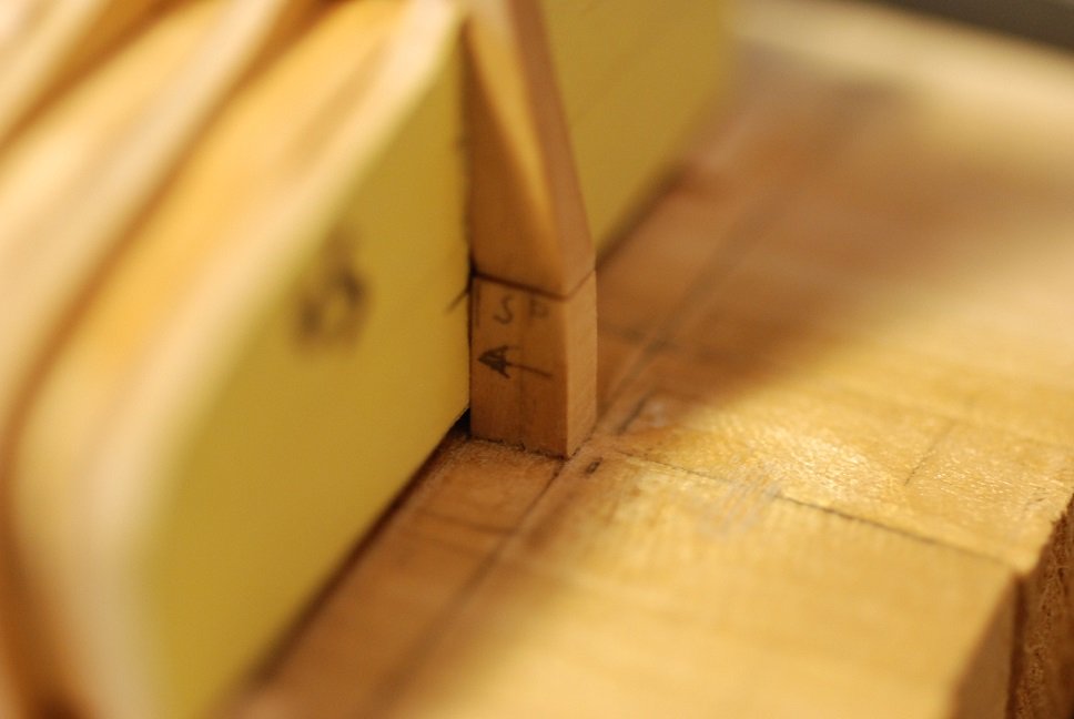
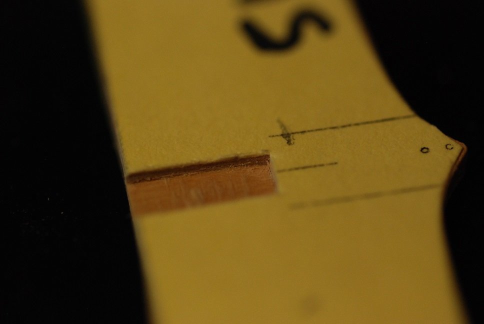
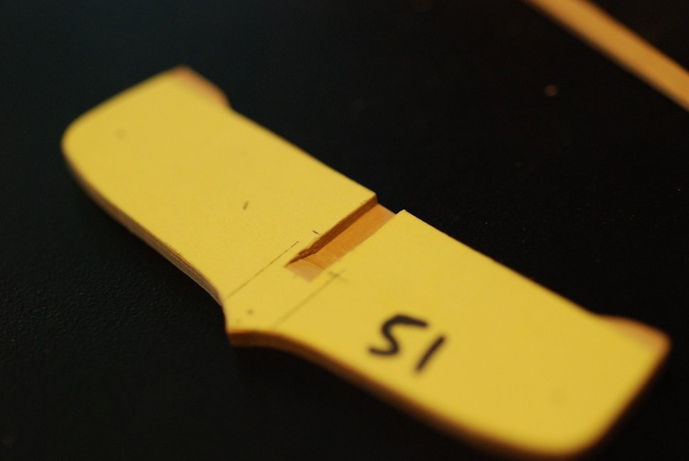
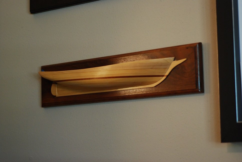
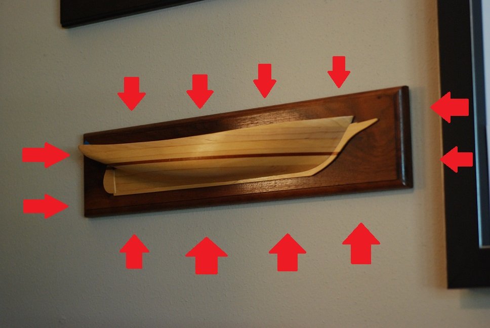
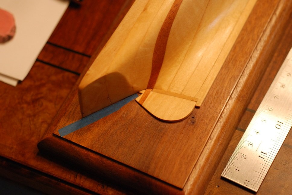
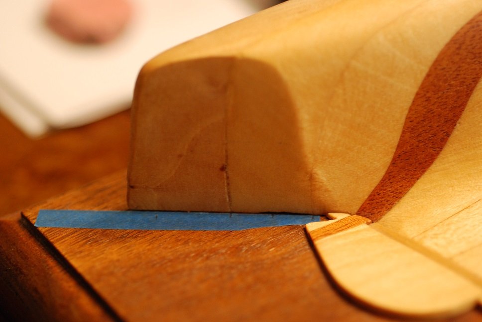
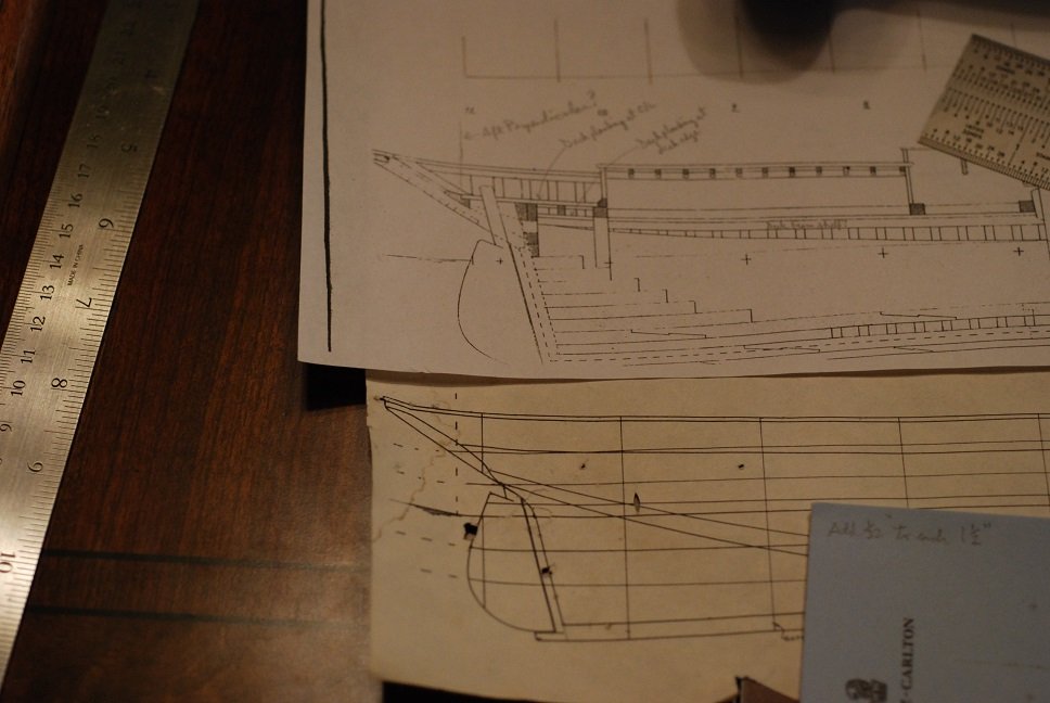
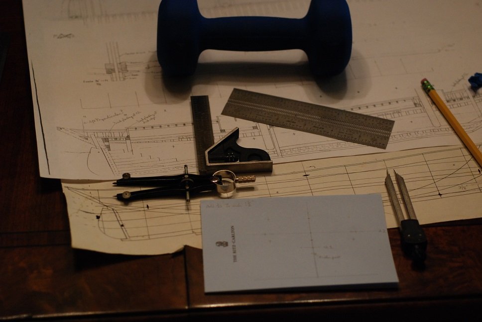
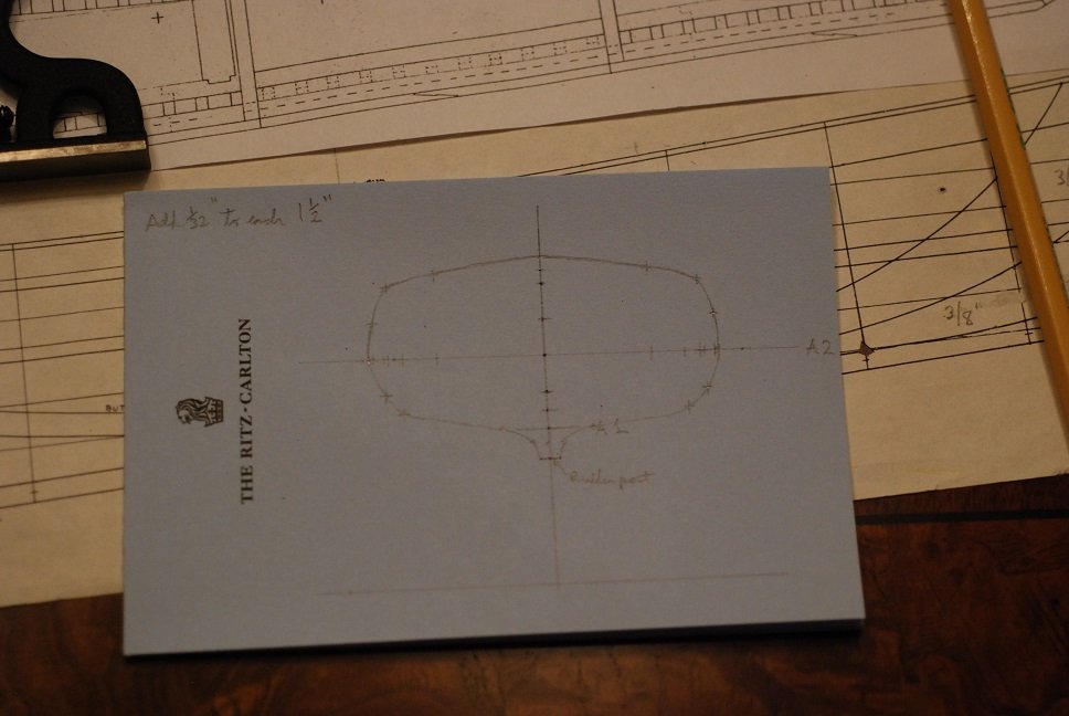
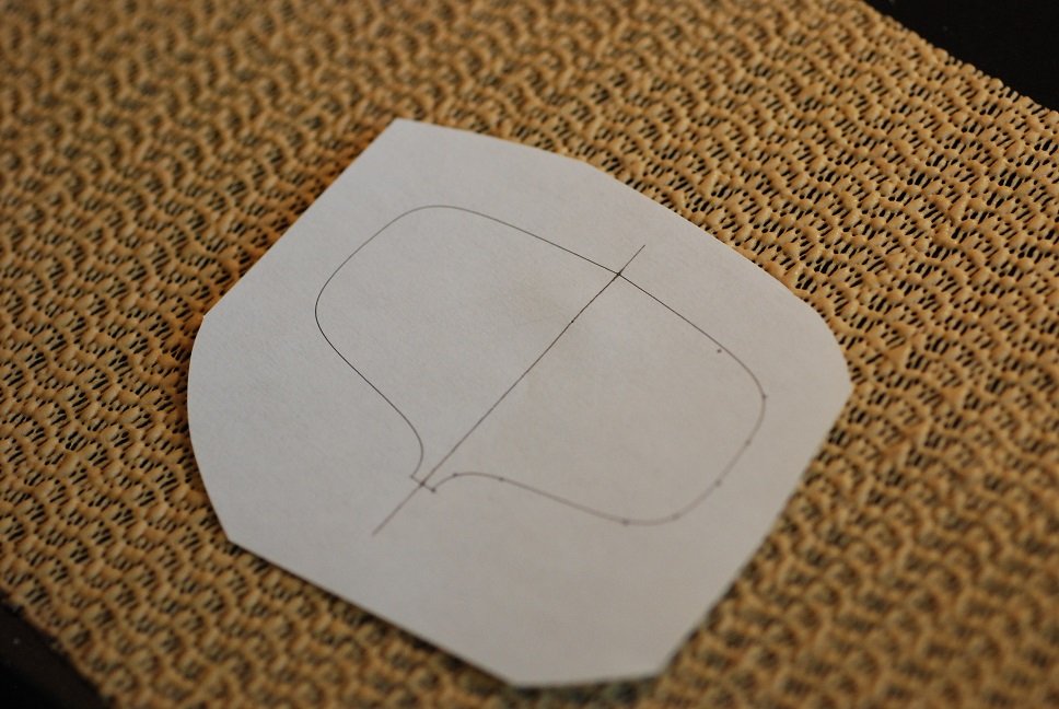
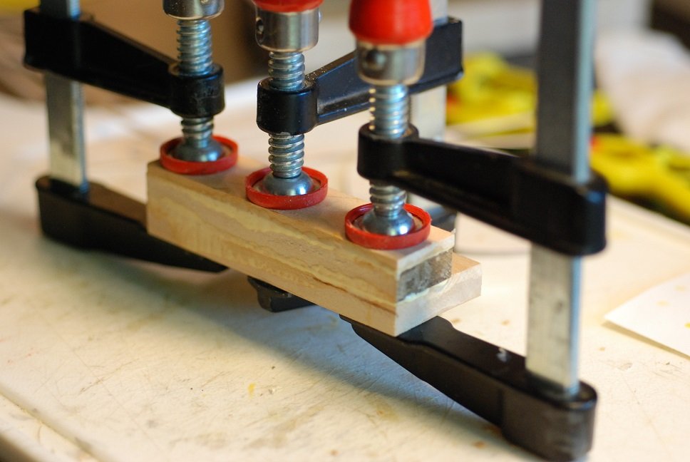
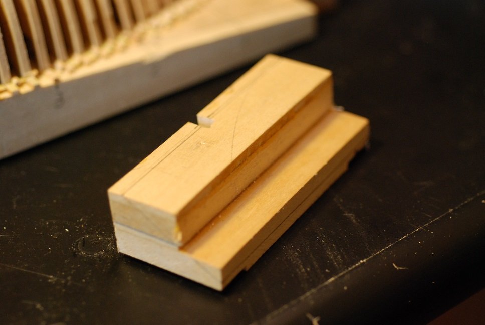
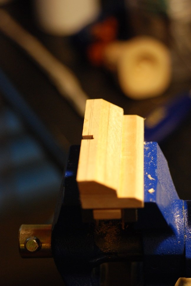
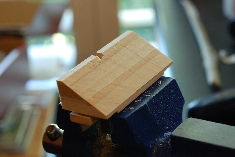
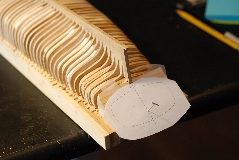
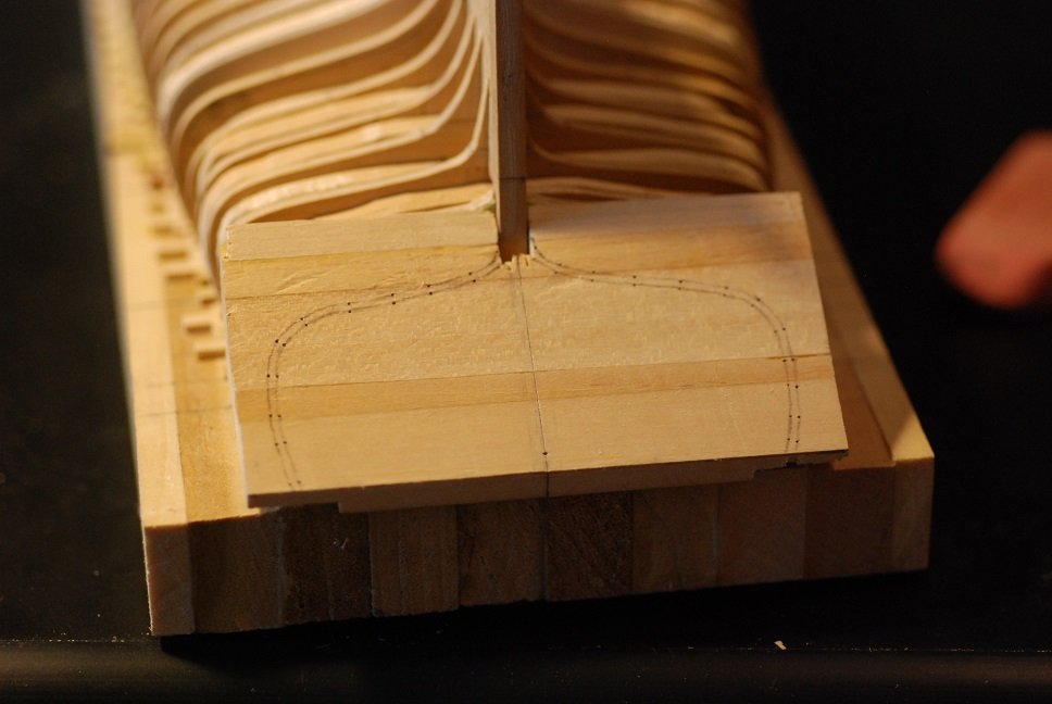
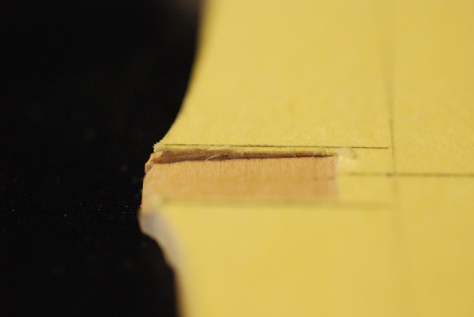
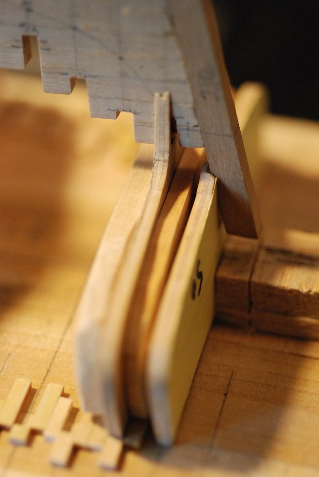
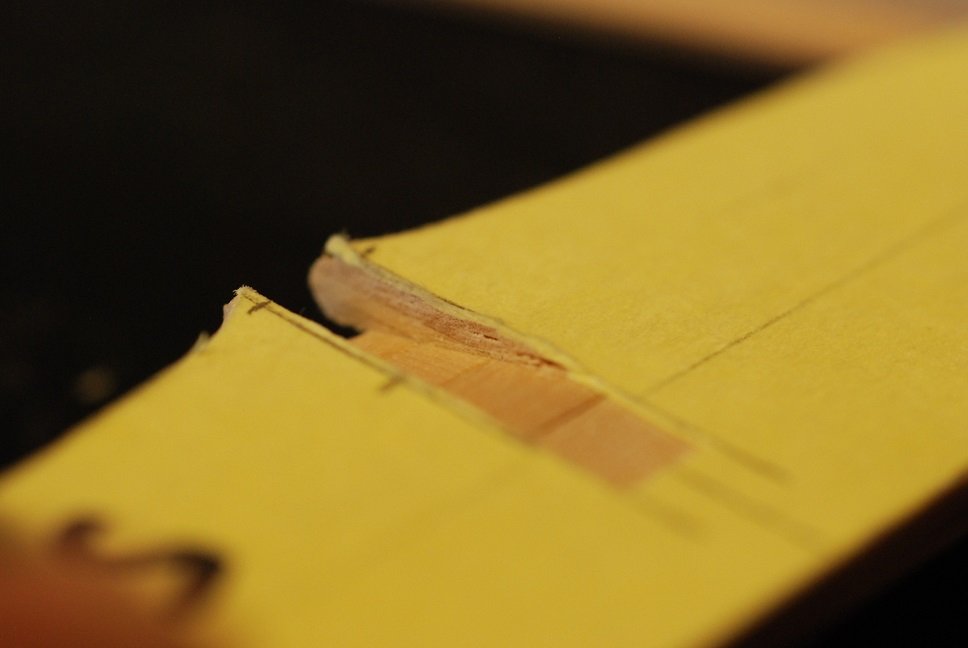
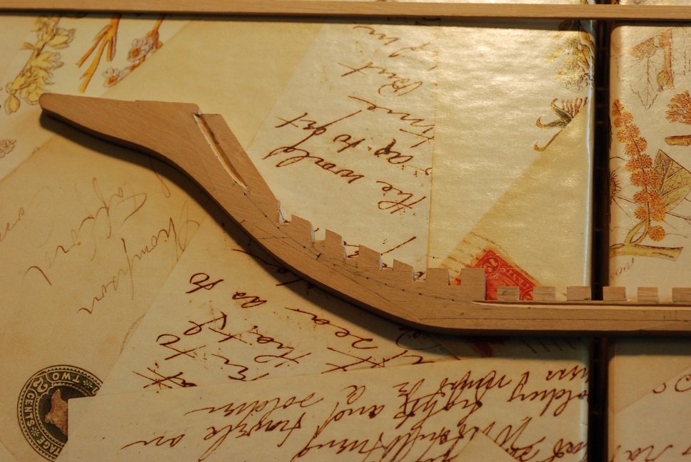
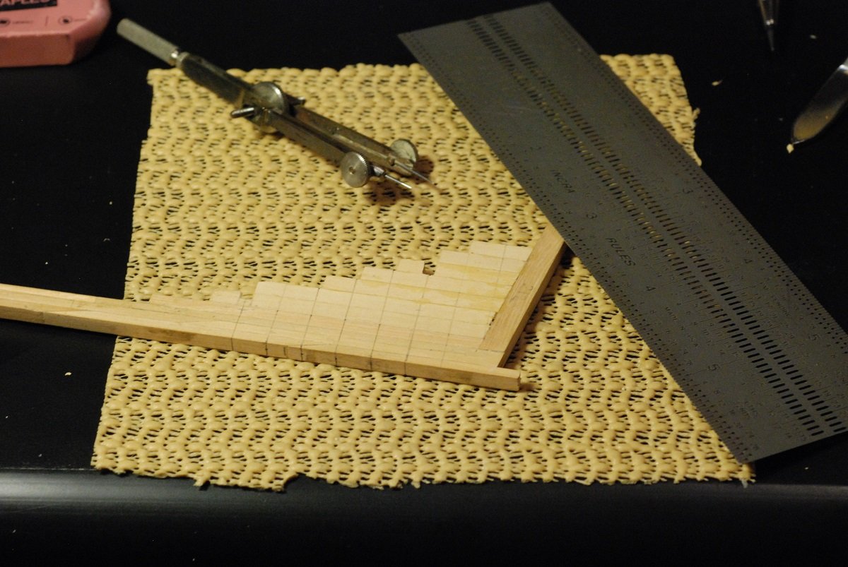
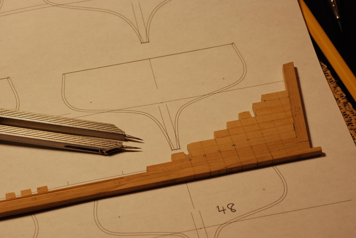
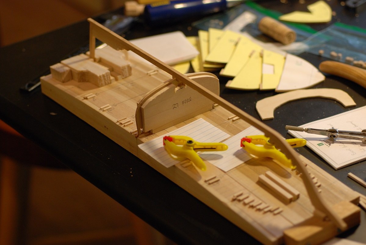
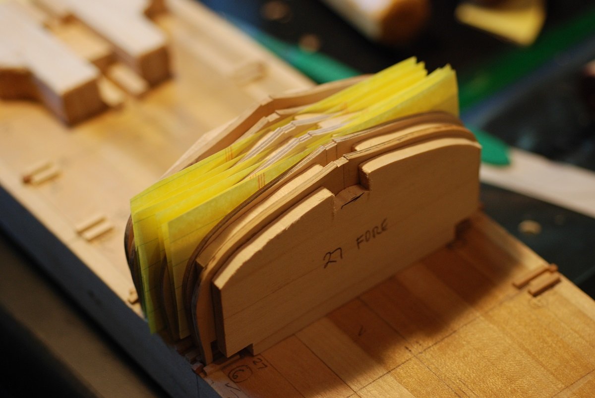
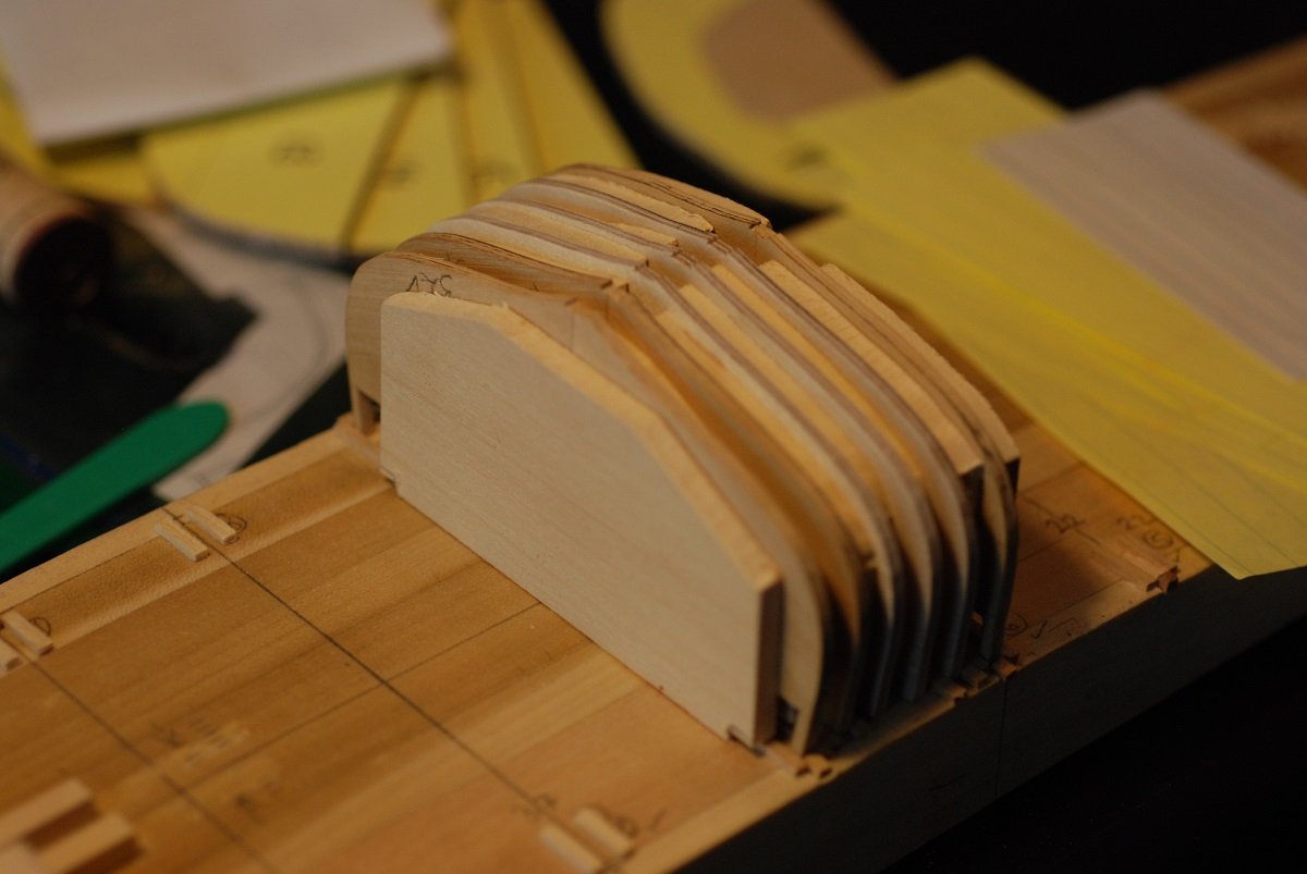
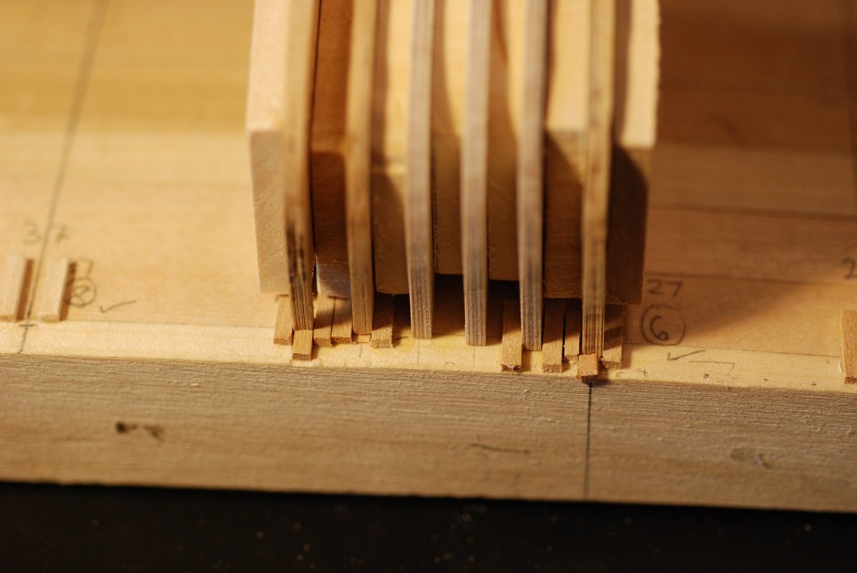
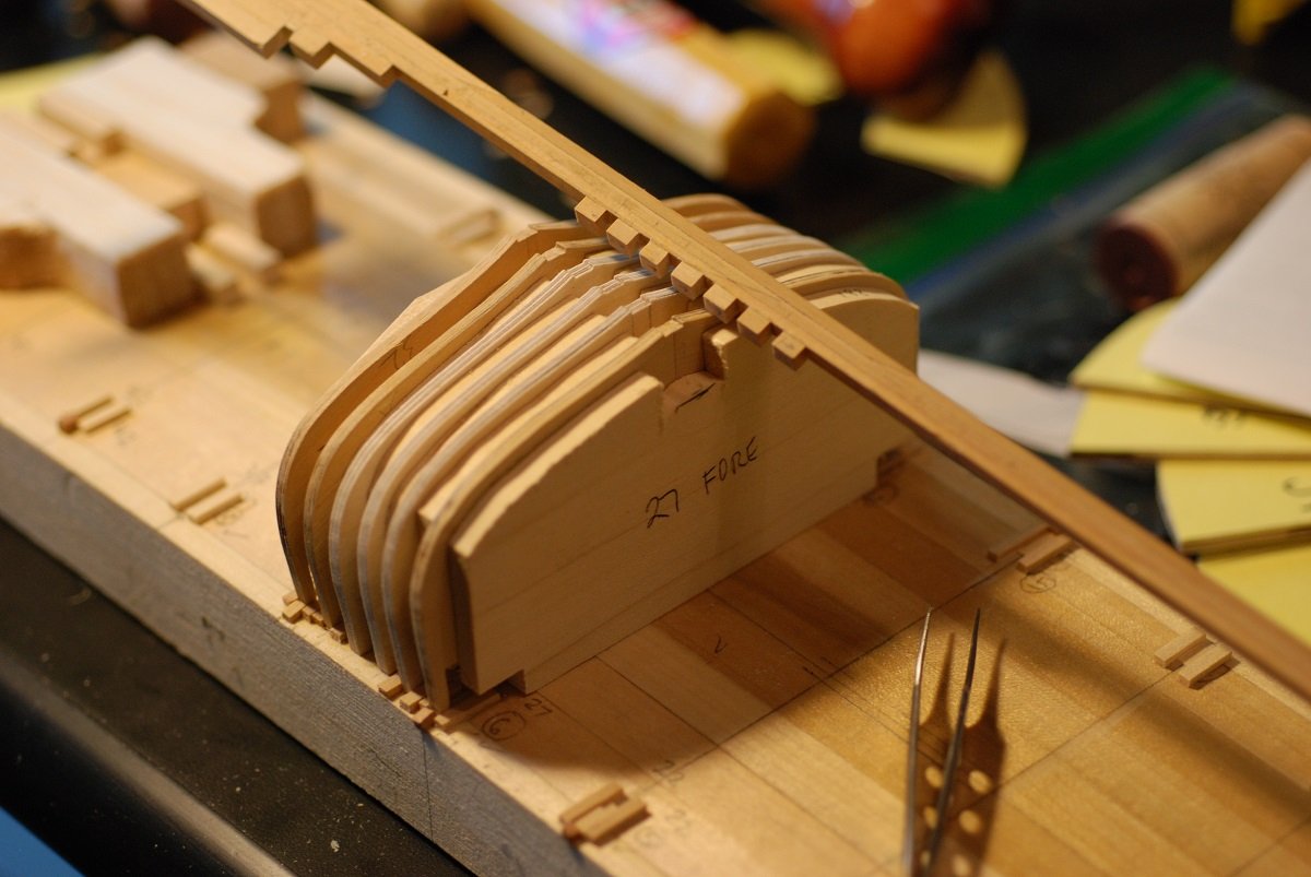
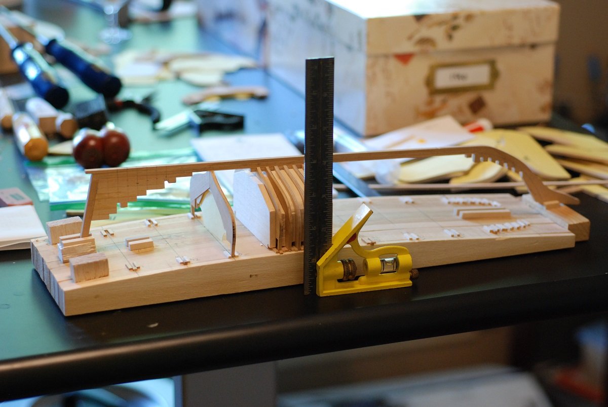
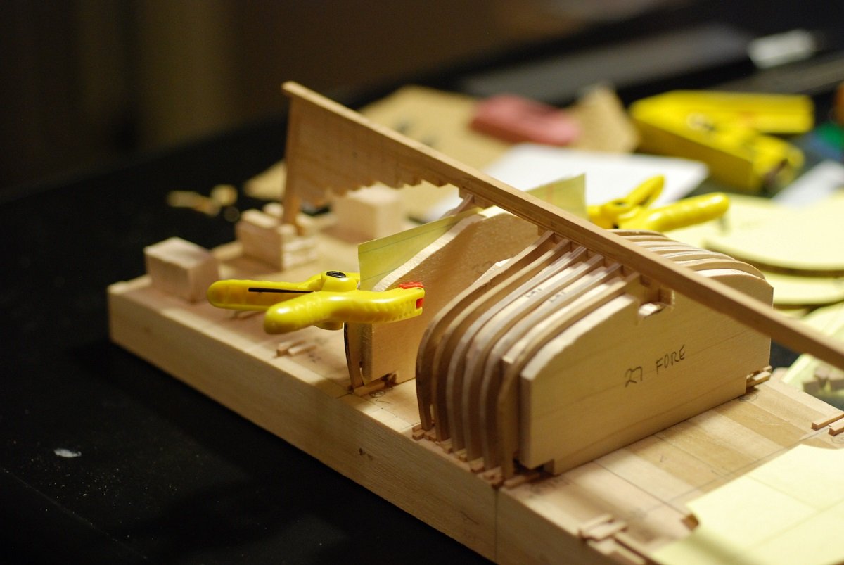
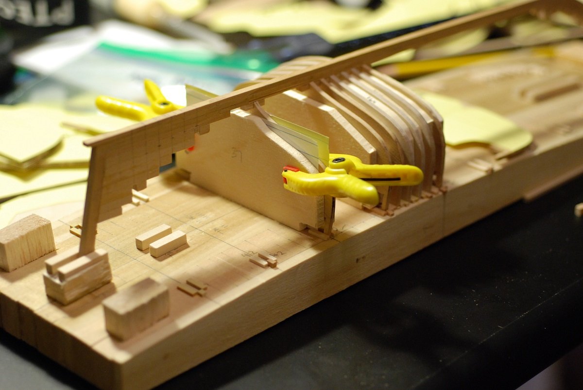
 In my last post, I showed how I had to cut frame #50 to accommodate the stern post. Unfortunately, that wasn’t the last frame. Frame 51 also exists, but it doesn’t articulate with the keel, deadwood, or sternpost. Rather, it will articulate with the framing for the transom, presumably fitting into what might be called a horn timber although I don’t think that’s quite the right term for this case. Feel free to correct my terminology. In the picture above, you can see how the bulkhead that will become frame 51 is unable to sit on its line indicated on the baseboard. The support for the stern post I had previously created ends right on the station line for frame 51. So I will have to do some carving on frame 51 just as I did for number 50. Maybe this will do it… Well, that certainly gets the upper part of the frame to sit on its station, but the frame is clearly tilted because the remainder is bumping up against the stern post. I carved out additional wood in a ramp-like fashion. Now frame 51 can sit vertically, parallel to all the other frames. As with frame 50, the shape of frame 51 is pretty arbitrary. I have no reference points to make sure that it is sitting neither too high nor too low on its station. This frame sits well above the waterline, so that can’t be used as a reference point. I am still facing the same problem with fairing the stern as I was facing during a previous post: How do I create some kind of guide for the shape of the stern so that I can accurately fair the aft frames as the planking leads into the transom? I really need some kind of filler block that simulates the shape of the transom, not only as viewed from astern but also in a way that follows the curvature of the planking. If only I had some kind of model to help me reproduce the 3-dimensional shape of the transom… Duh! The resource I needed was hanging on the wall of my shop. “Oh, and the next two hours tripped by on rosy wings!” (More like a few days…) I built this half model of the Mary Day while attending a class at the Wooden Boat School in 2004. It was built based on the lines drawings I had received from Barry and Jen a few years earlier, before the builders plans had been uncovered. It was the first of two I made; the other one went to them and is now at their office. I am certainly glad now to have made two models. It never occurred to me that I would use my own half model in the same way as boatbuilders have historically used half models: to reconstruct the hull at full scale. OK, I won’t be doing it at full scale, but still it’s a thrill to have this resource available so that I can directly transfer dimensions to a block of wood and fabricate the filler block I need. I put a strip of painters tape along the transom so I could mark up some reference points. And where two lifts of wood meet, a very convenient waterline is visible that can be cross-referenced on the lines drawing. Another good reference point turns out to be where the bottom of the transom meets the stern post. Here, the builders plan is placed just above the lines drawing and a weight secures them relative to each other. I did this to get a sense of how different the scales were between the two plans. The lines drawing shows the waterlines A1 and A2 and where they cross the transom. The old lines drawing has a spacing between stations of 1 inch plus 13/32”. The builder’s plan has spacing of 1 inch plus 14/32”. So, over about 1-1/2”, there is a difference of about 1/32”. This is a difference in scale of about 2%, with the builders plan slightly larger than the lines plan. But this is plenty accurate enough to generate a useful transom pattern and filler block. Here are the tools I used to transfer dimensions. They include a small carpenter’s square, a compass, a 1/32” Incra rule, and calipers. The dimensions taken off the model were transferred to a transom drawing on the blue paper. On the drawing, reference lines included the (horizontal) waterlines labeled A1 and A2. At the bottom is the junction of the transom with the stern post. Then of course the centerline. The distance from the transom-stern post junction to waterlines A1 and A2 were measured off the model, and slightly adjusted given the differences in scale. The width of the transom on the half model was measured using the Incra rule, which worked better than the carpenter’s square or the calipers. The tips of the calipers could not get into the point where the half model meets its mounting board, but the Incra rule could sit directly up against the transom. The distances were transferred to the drawing using the compass. Intermediate points between the waterlines A1 and A2 were used to fill out the shape of the curve. Then I created a new Rhino file and entered the coordinates, then used Rhino’s curve drawing capabilities to create a smooth curve that traveled through all the points. The mirror function duplicated the curve for each side, and gives us a nice transom pattern. Now I need a block of wood to serve as the transom filler block. I glued up some ¼” basswood, …and a notch was cut into it using the table saw, so the block could sit against the sternpost. Now I am planing it to shape. A strip of wood was screwed into the bottom surface so it could be held in the vise. One of the basswood pieces wasn’t big enough, leaving a defect in what will become the face of the transom. So a filler was glued in place. The edges were marked at an angle corresponding to the angle of the transom, and the blocks were planed down to the line. The pattern was then put in place with its bottom edge against the sternpost, and a pin was used to accurately place the centerline of the pattern on the centerline of the filler block. The transom pattern marks the outer surface of the hull, so the thickness of the planking needs to be accounted for. So purely as a starting point, the thickness of the planks (3/64”) was marked along the transom pattern. This of course is not structurally accurate, because the planking thickness actually changes depending on the angle with which the planks meet the transom. But I will leave that for the next post, as I am already up to 21 pictures.
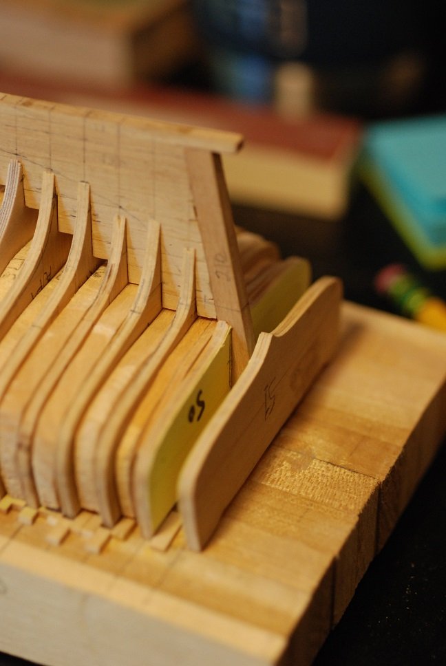
-
I feel reassured by all the posts indicating people having trouble with their models' transoms/sterns...
-
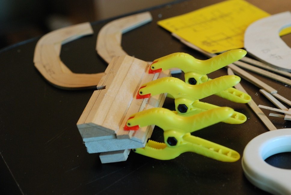
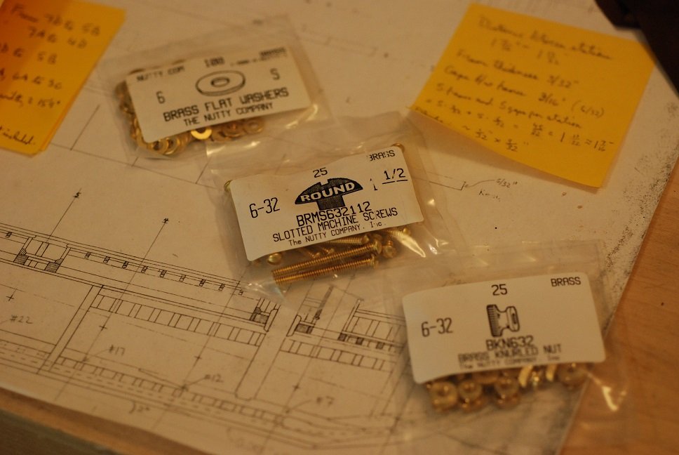
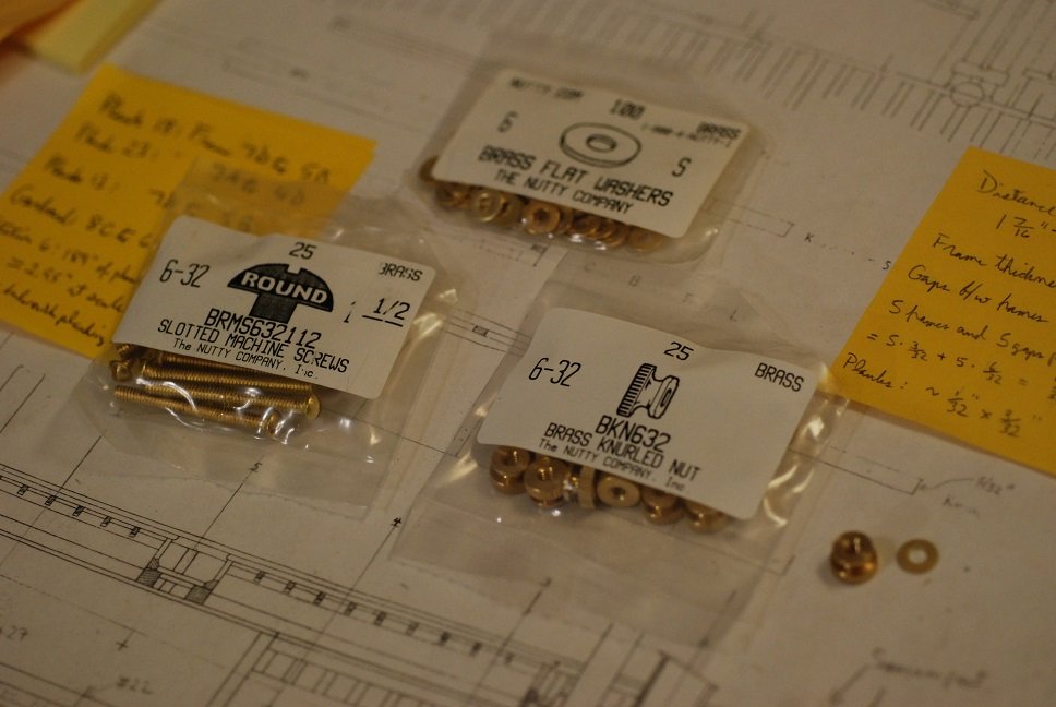
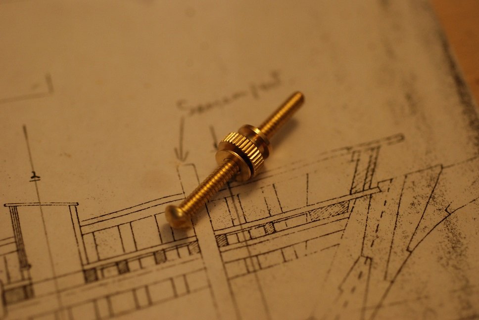
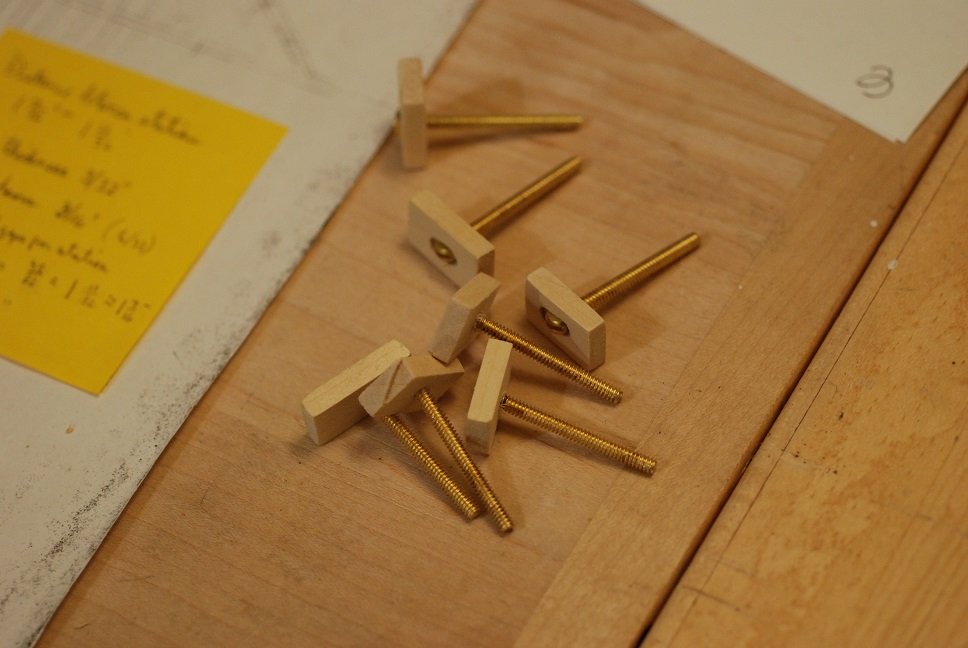
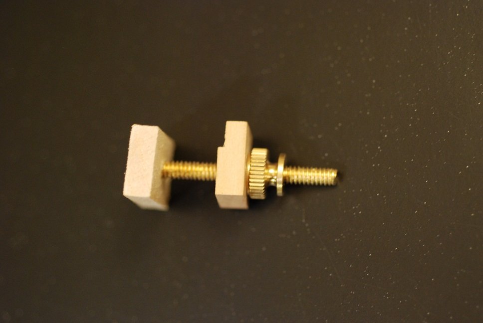
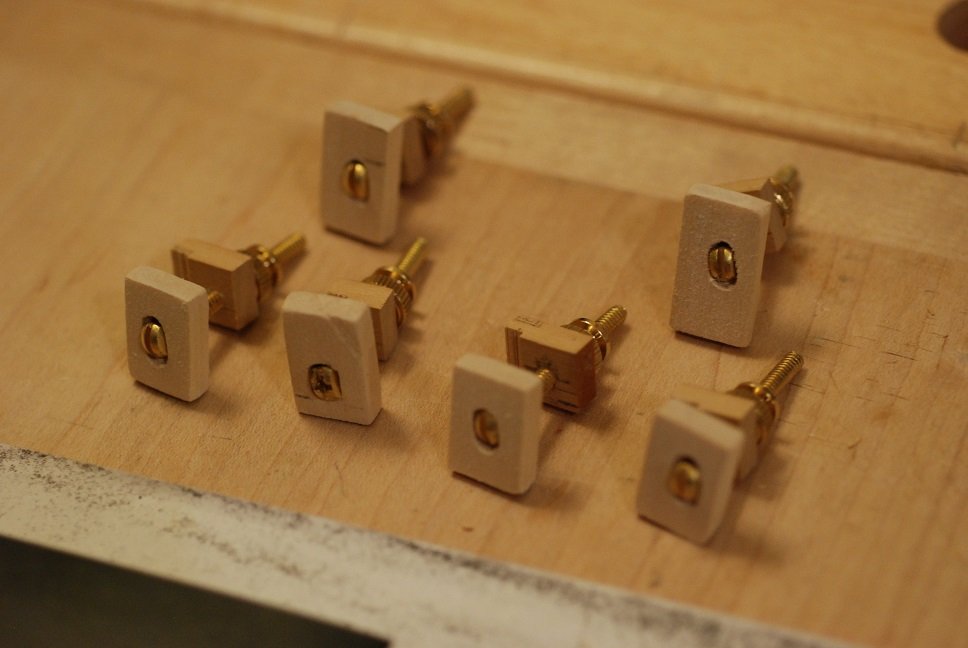
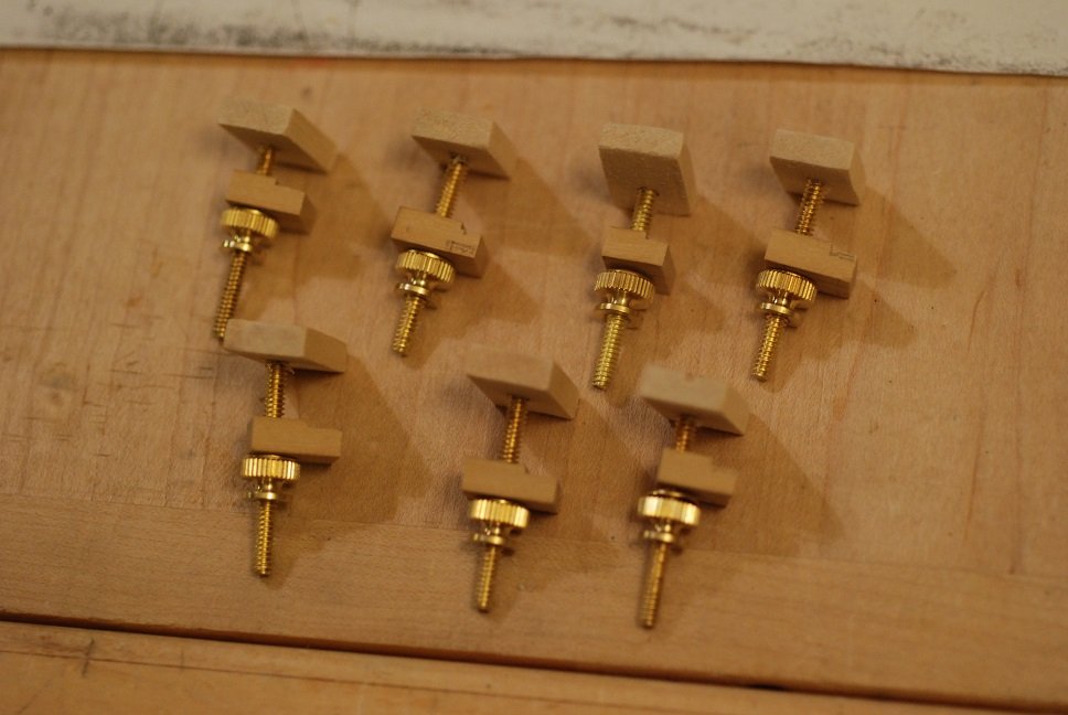
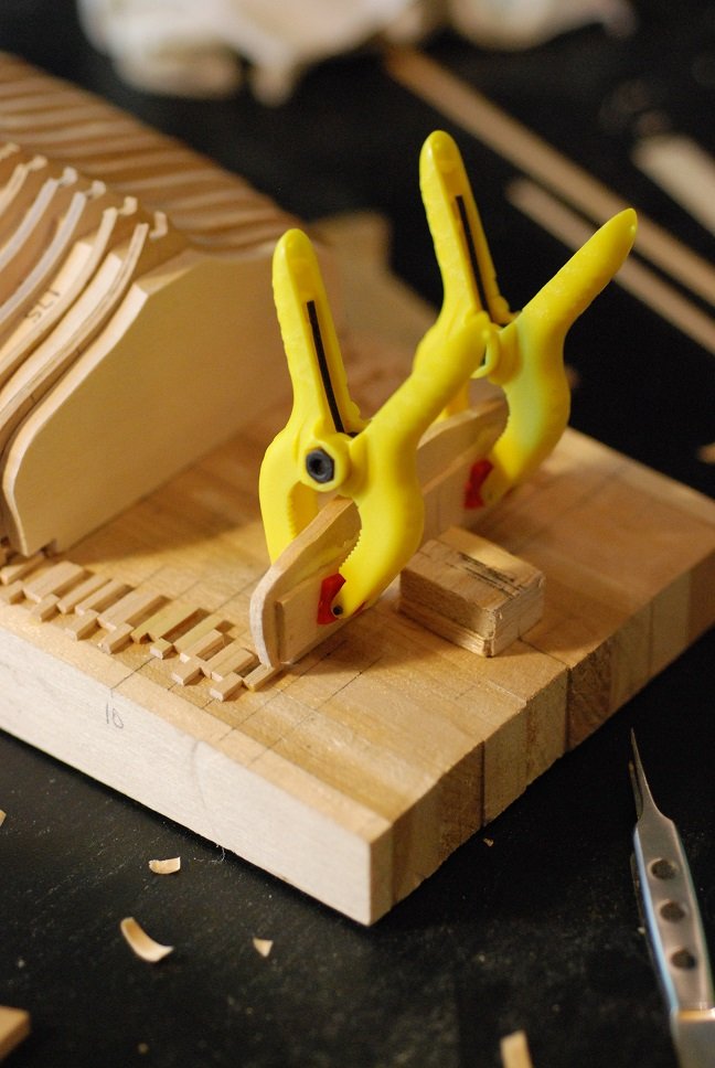
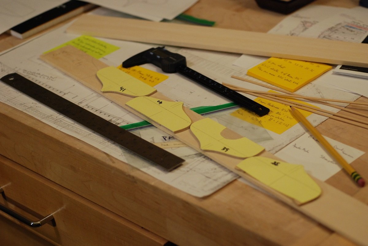
I am looking ahead to planking and thinking about how to hold a freshly glued plank against the frames. Just in case I go ahead and turn these bulwarks into frames, I was envisioning some clamps along the lines of what Ed Tosti makes in his Naiad Frigate series. What follows is what I have ended up with, which will probably be modified further once I actually reach the point of planking. Not being able to consistently find brass screws of the size I wanted, nor being at all able to find knurled nuts, I went online and found this supplier of brass screws with round heads, and associated washers and knurled nuts. I pictured being able to use these with two pieces of wood to make an effective clamp for the 3/64” planking. The round heads of the screws were ground down so that they were flat-sided. These were then sunk into pieces of 3/16” thickness basswood drilled for the shaft of the screw, but also countersunk with a flat-sided hole that the head of the screw would sit within and not be able to rotate. I used a 3/16” thick piece of boxwood for the other wood piece, and created a notch along one edge that was just shy of 3/64” deep. This piece is retained by a washer and knurled nut. I made a variety of different shapes of basswood pieces. They typically measure 7/8” by ½”. I also made a variety of shapes and sizes for the boxwood clamps. The key feature is to make sure that notch in the boxwood piece is not too deep, as it has to be able to press the 3/64” thickness planking strips against the frames and keep them abutted against the next plank over. A fun little diversion that I hope will end up being useful!
-
Mark, even though I have not bought a set of the Russian chisels, I would be interested in seeing his honing instructions. Can you PM me as well? Thanks.
-
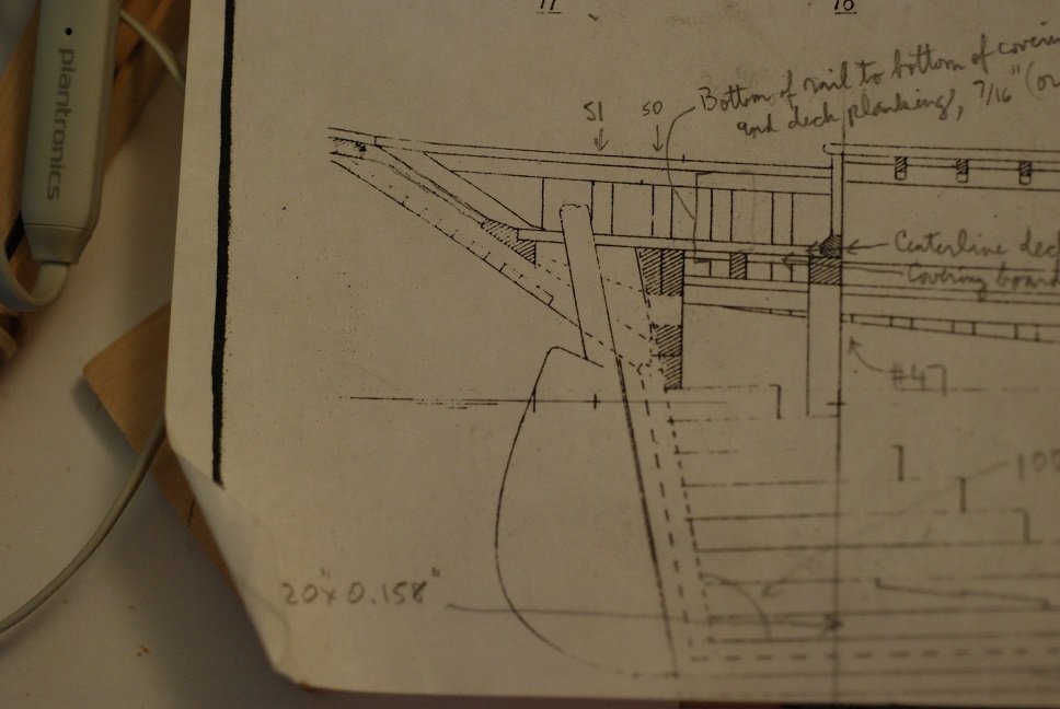
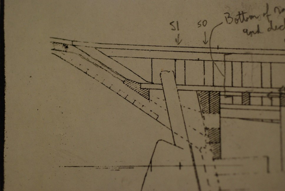
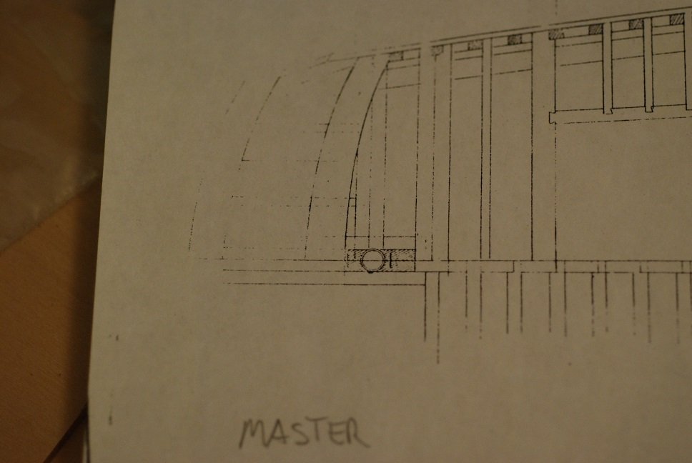
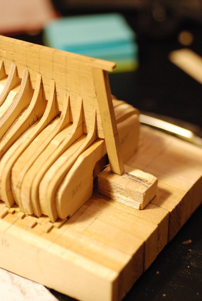
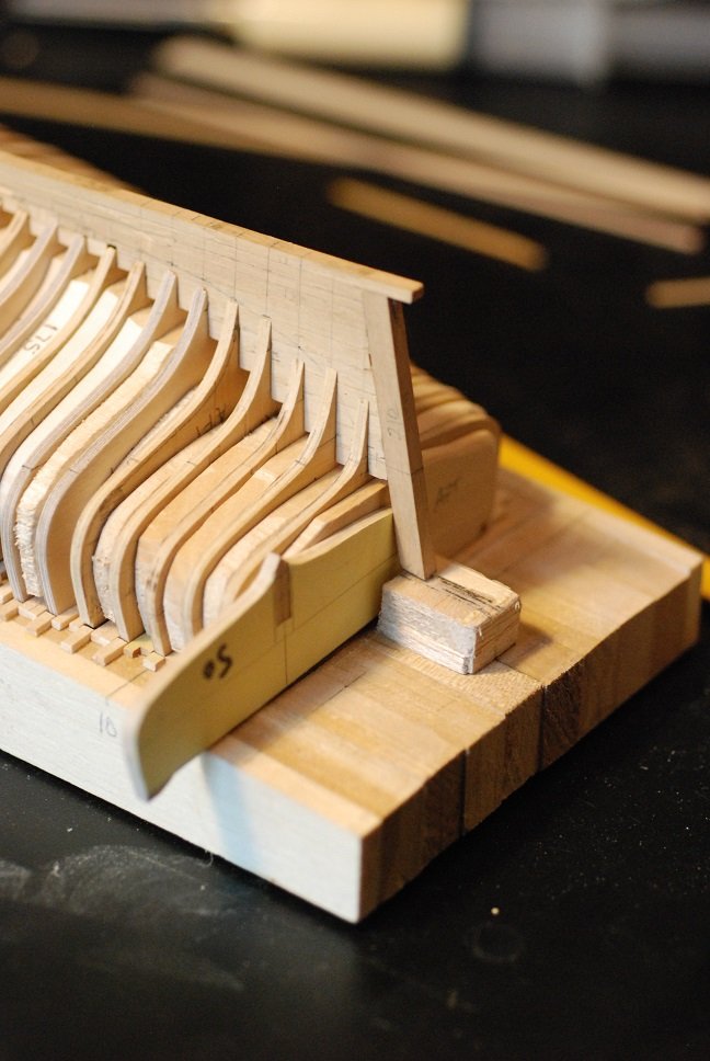
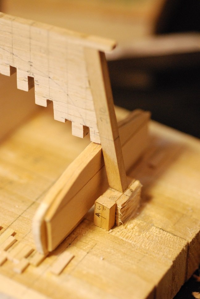
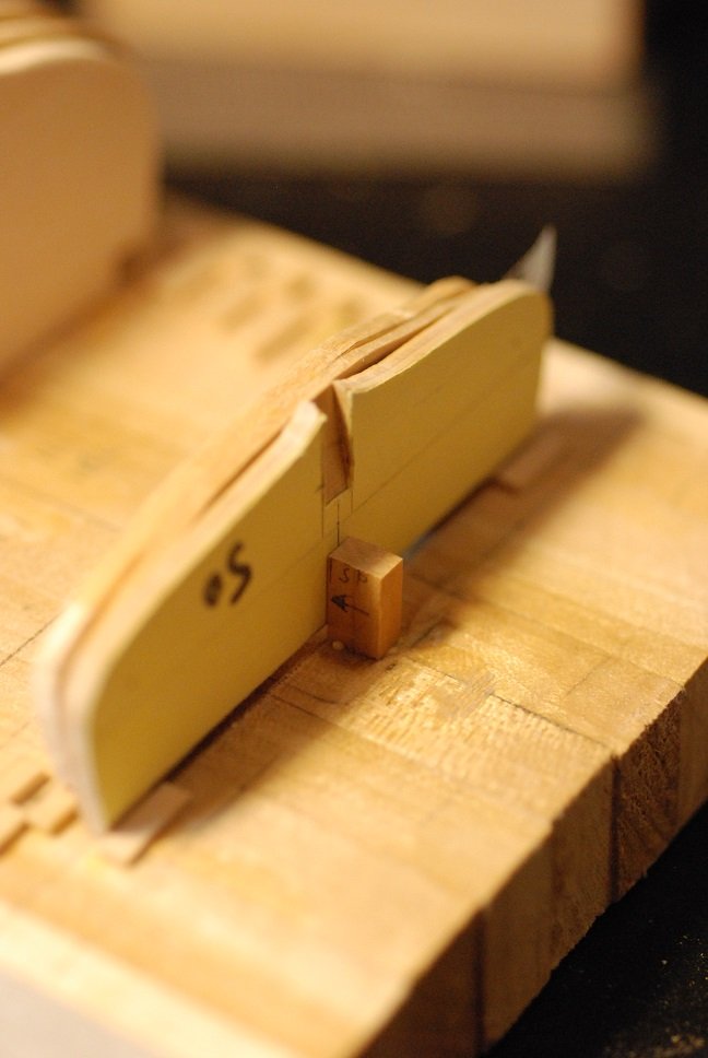
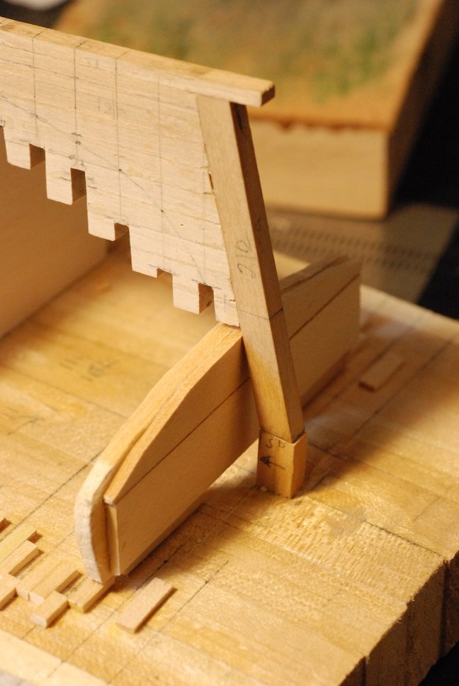
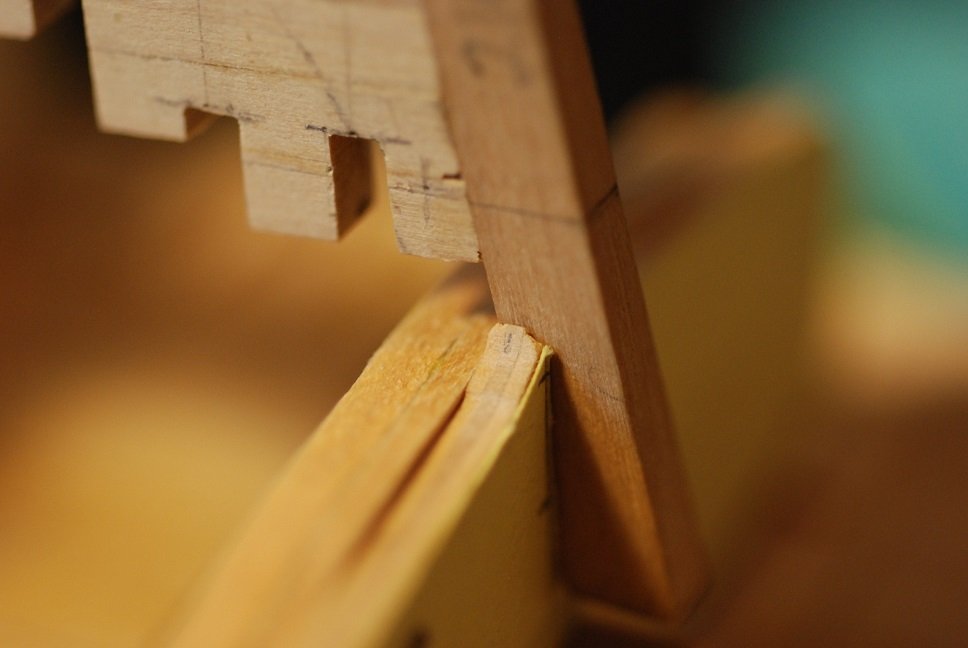
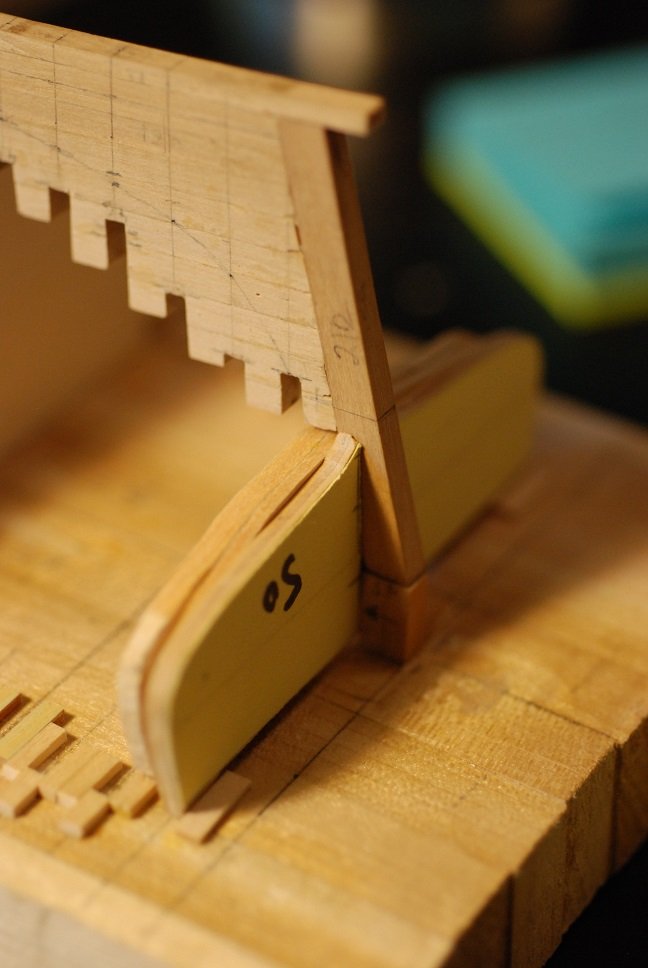
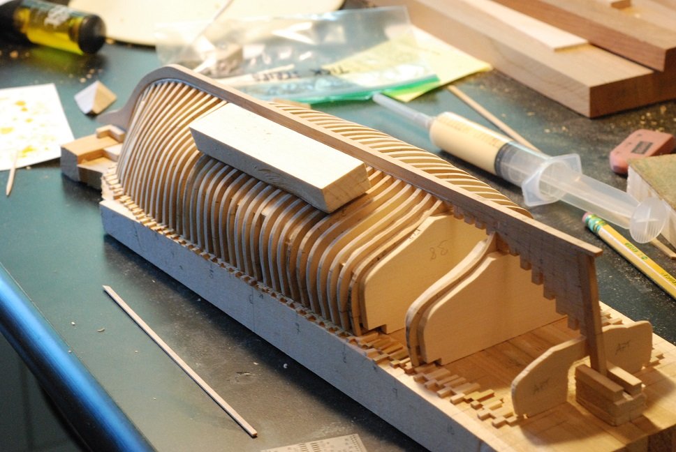
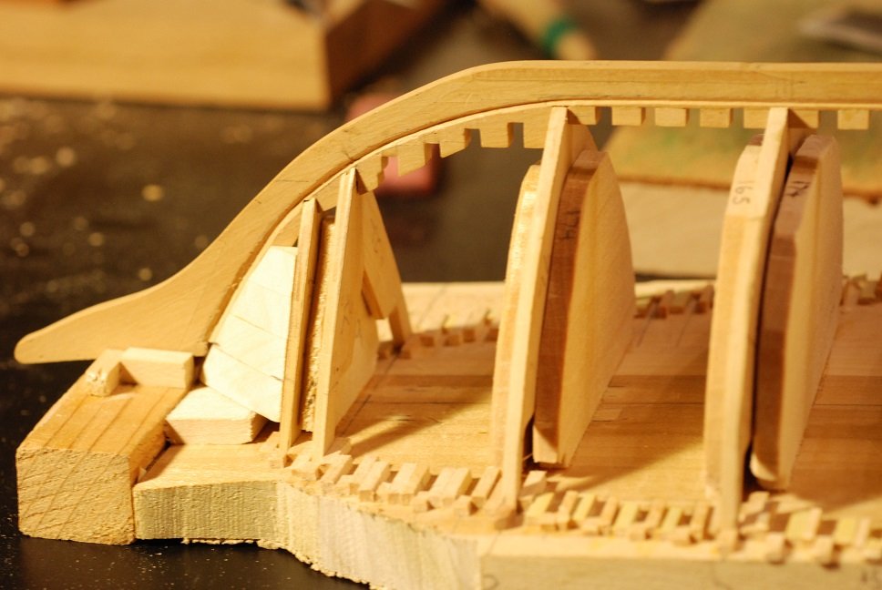
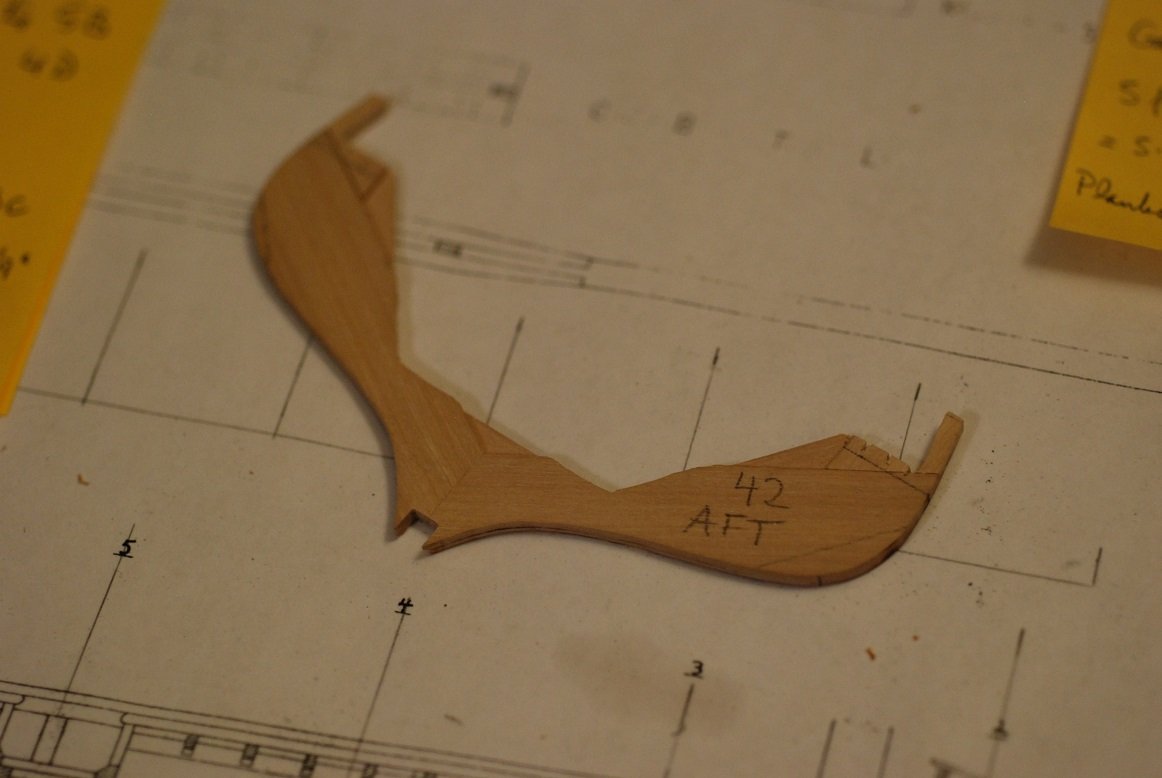
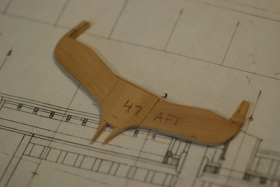
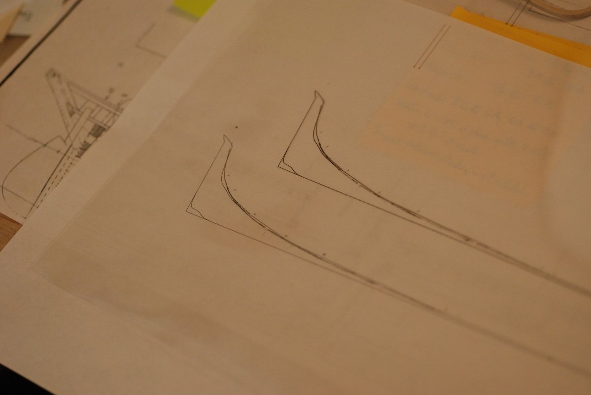
Fairing of the bow and the midships frames has gone more smoothly (ha, get it?) than I anticipated. I would like to think that I could carry on through the stern and get through it all, but it has been pointed out to me that fairing frames 1-49 without frames 50 and 51 as well as some kind of transom filler could result in a distorted stern. So I need to do something to get those two last frames in place, or at least something that approximates them. At this time, I don’t plan on permanently installing a transom filler block. I want to try to emulate the actual structure of the boat. Well then, here is what that looks like! (An overhead view is also provided a little further on.) I am going to have to infer a lot of information from these construction plans if I really want to imitate the actual hull structure. This close-up image shows those last two frames (50 and 51) and their relation to the stern post and transom. Going straight south on the diagram from the penciled-in 50, you pass through the caprail and a clamp associated with it (is there a name for that?), then into the bulwark stanchion portion of frame 50. Then you cross the centerline planking, then there are two deck beams applied to one another that travel athwartships, with a camber that corresponds to the crown of the deck. Then it appears there is a gap, then two more transverse beams that are applied to the forward surface of the stern post. These rest upon the top member of the deadwood. I presume that they extend to the inner surfaces of frame 50. On the overhead view of the same area, the two deck beams applied to one another are shown above the centerline, and frame 50 is shown below the centerline. The articulation of the deck beams with frame 50 at the edge of the deck shows that the deck beams are notched to accommodate frame 50 as it comes up to deck level and becomes a bulwark stanchion, depicted by the small shaded rectangle. The location of frame 51 is along the forward edge of the round cutout for the rudder post. There is another deck beam just aft of frame 51. In this image we have the keel with deadwood and sternpost, and all frames up to number 49. So the next issue is how to fit frame 50 in place. We currently have this support block under the sternpost that is getting in the way. There is also a sacrificial piece of wood just aft of frame 49, similar to the other pieces that sit between the frames further forward, but thinner. Here is what we are up against in trying to put frame 50 in place. I am going to have to thicken the sacrificial piece so it is the same thickness as the others. So I glued pieces of 1/16” basswood sheet to it. The support block for the sternpost is currently not getting in the way of frame 50. In order to sit up against the sternpost, I had to carve out a ramp-like portion from the frame and test-fit it. Not there yet. This is how low the sternpost and deadwood should sit once I have carved enough wood out from frame 50. Next to the bulky support piece, I have a smaller piece of wood that will replace it with a lower profile. Something like this. Again, if I have cut a deep enough notch in frame 50, the deadwood and sternpost will end up like this. We are clearly not there yet, as the deadwood is sitting well higher than it should. The 1/8” chisel under the microscope was just the thing for carving out this portion of wood. This frame was built up with 3 layers of 1/16” boxwood, and the glue lines were a very nice guideline to making sure I was carving a level ramp. After much trial and error, here is where I ended up. It’s worth noting that I have no idea if the height of the frame is correct. I am totally guessing on this frame’s position, because there is no waterline on it to serve as a reference point. I used a piece of paper as a sort of feeler gauge to make sure the keel and sternpost were sitting low enough. Next post is going to be more working through the transom.

-
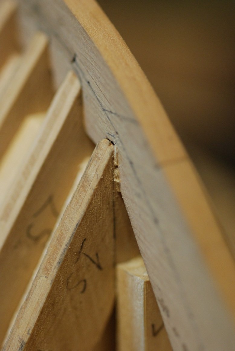
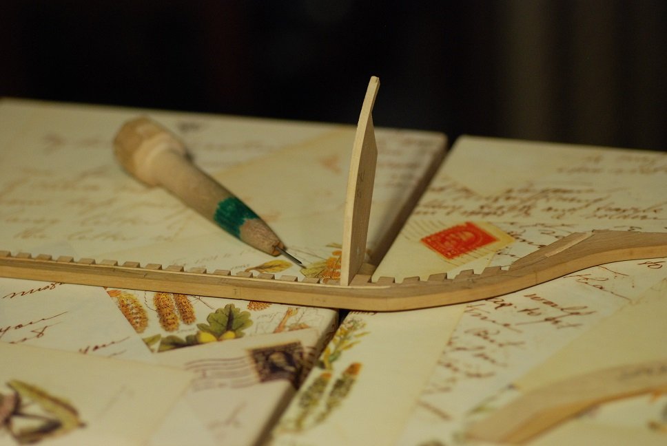
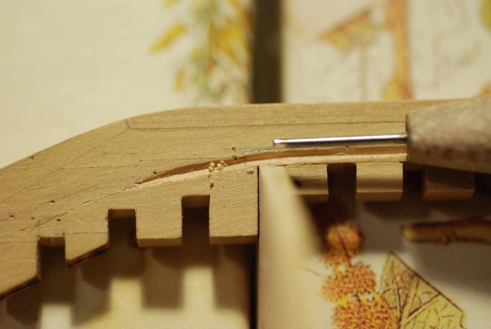
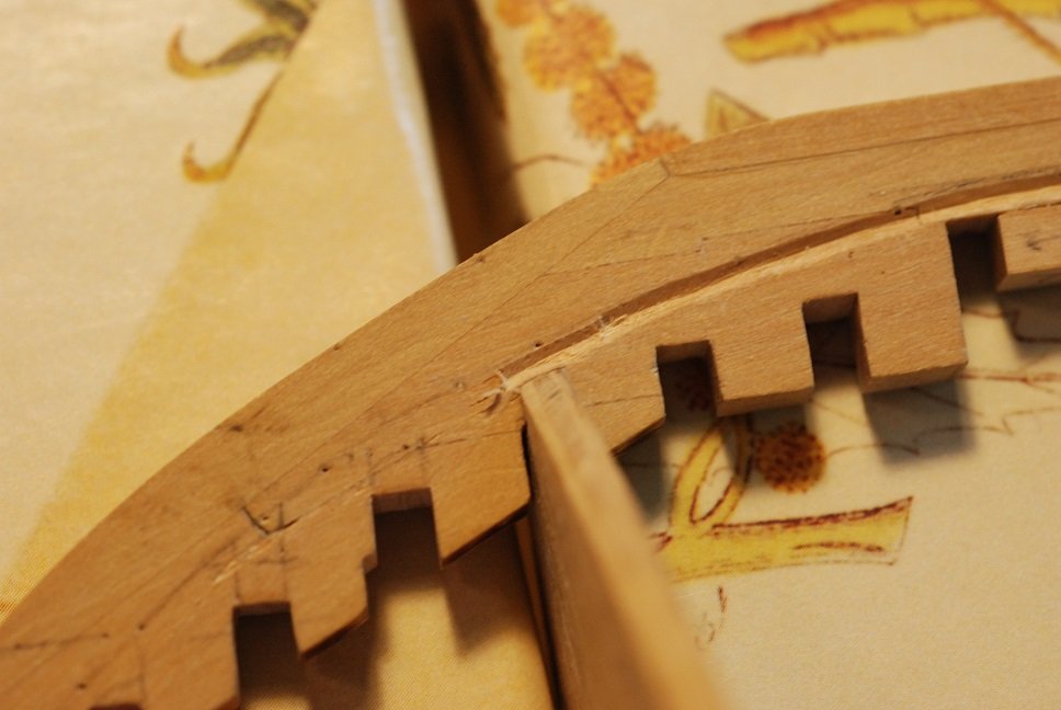
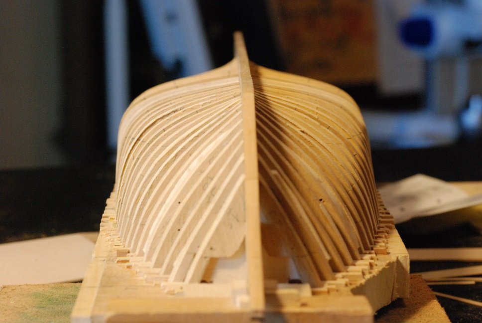
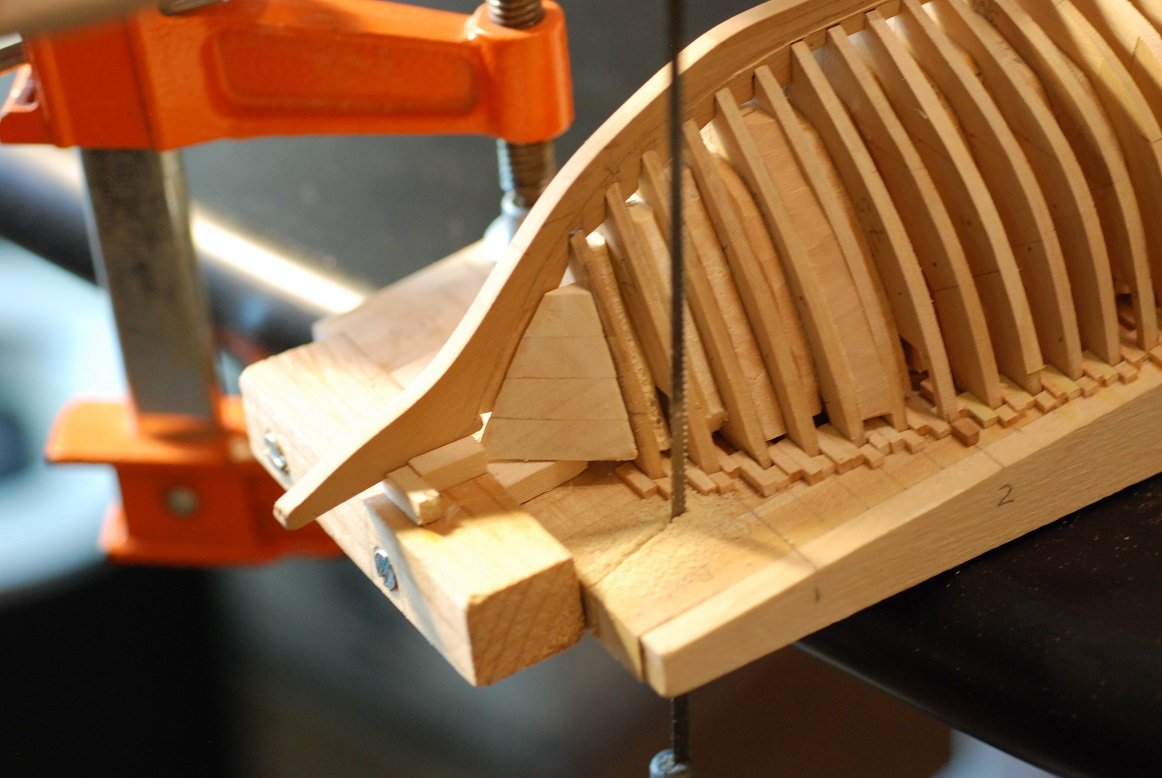
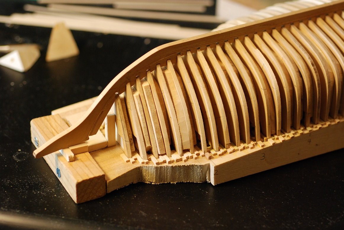
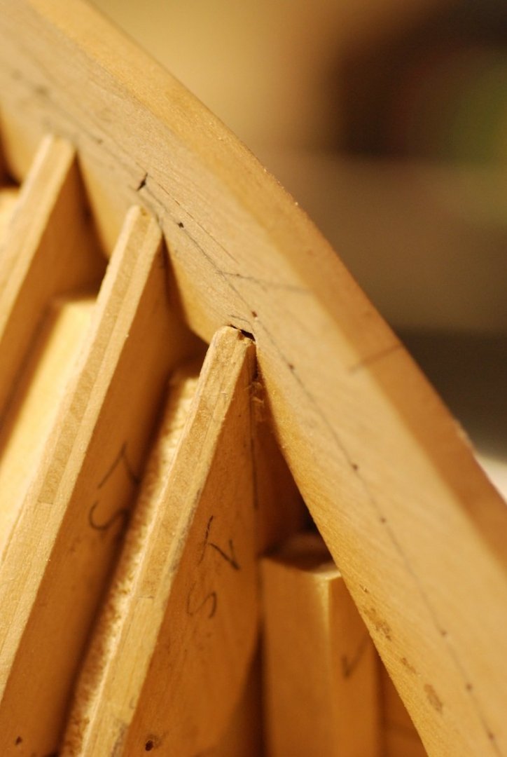
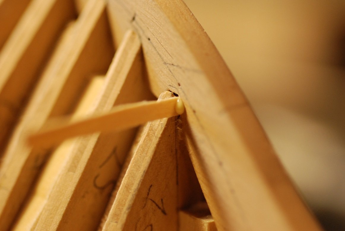
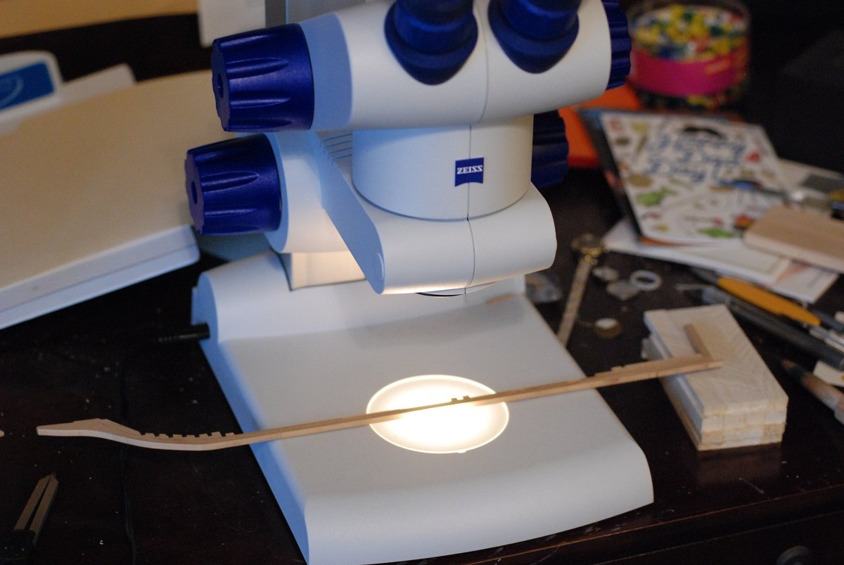
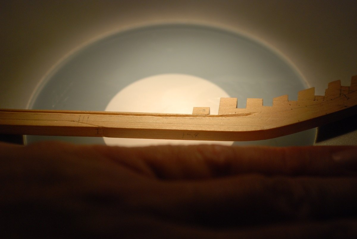
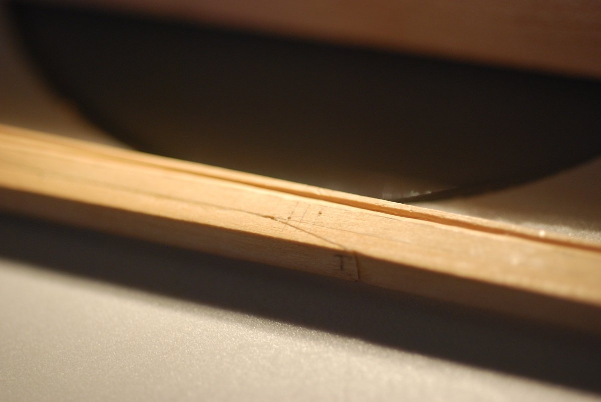
We are at the point of fairing the shape of the hull. This picture shows the sanding block I am using, which has 100 grit adhesive backed sandpaper on its face-down surface. The general approach was to sand an area such as the starboard bow frames to knock off the hard corners of the frames, then see which frames really stood proud from the rest and bring them into alignment. Then find the frames that are sitting low to their neighbors and glue in shims. The shims I used were 1/64” thickness strips of basswood, which sanded down very easily once applied. The happy end result was that the fairing of the frames in general went faster than I expected. But I still needed to work the shape of the frames into the rabbet. This had mostly been done where the rabbet is straight, but in the bow the rabbet quickly changes in configuration. I needed a way to hold the keel against a given frame and carve out the rabbet in that immediate area. And so this jig was born. I am using two photo boxes next to one another to hold a particular frame in place, then the keel is put into place next to it. This enables me to use one of my micro-chisels to sight down the curve of the frame and cut out the correct angle of the rabbet. Here is the perspective along the edge of a frame. This is station 2, about frame number 7. In this way, I worked along the curve of the stem frame by frame, now up to frame number 4. There are pin marks in the wood of the keel that indicate the rabbet line. These are rather deep and may end up being visible when things get glued up. So they will have to be filled in with filler. The rabbet has been extended to frame number 2. This particular frame falls at the level of a joint between two of the pieces of the stem. The rabbet is now continuous through the course of the stem. I learned a lot working on the rabbet on the starboard side, which made working on the port side a lot quicker and cleaner. Here are a couple of strips of wood I am using for checking the fairness. One is of actual planking thickness, 3/64”. The other is a much thinner 1/64” piece. It has been useful in checking the fairness in areas where there is a lot of twist. I don’t have a “before” picture, but this one was taken after fairing at least the port side of the bow (on the left in this image). Some of the frames demonstrate basswood shims on their surface. So as I said, I was pleased with how relatively quickly the fairing has gone so far. The last time I faired a hull was in the late 1990s since my last model took so long, and I remember thinking it was a tedious process. Speaking of which, I am often surprised by people who look at projects such as this and say, “That must be really tedious!” I always respond by saying that “tedious” has such a negative connotation, and that most of what we do, while perhaps slow, is so enjoyable that we would never call it “tedious”. Except for fairing… Anyway, stopping here. The fairing of the bow and midships is very straightforward compared to what is to come: What do I do about the transom?

-
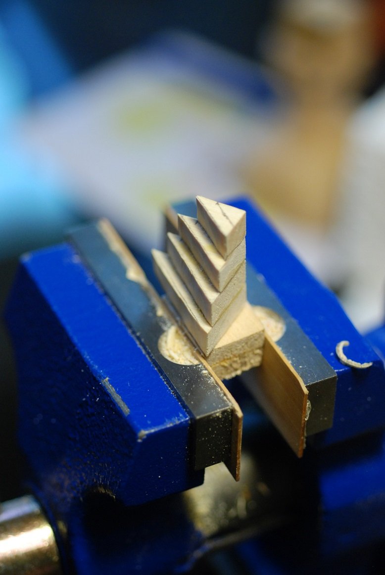
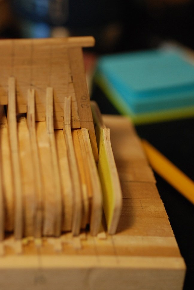
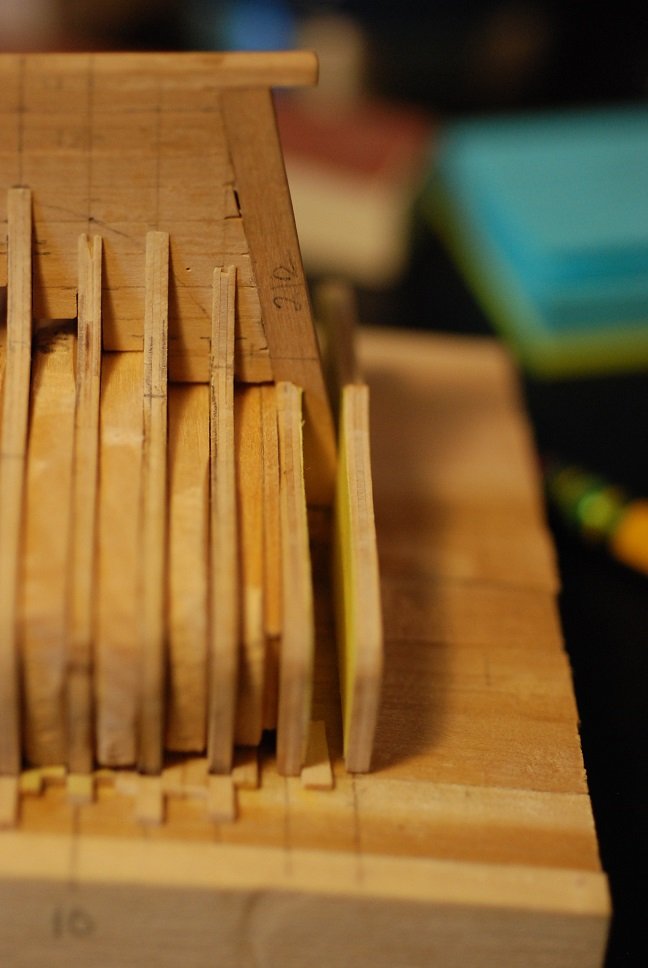
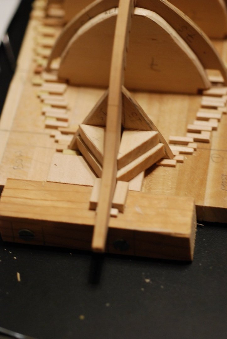
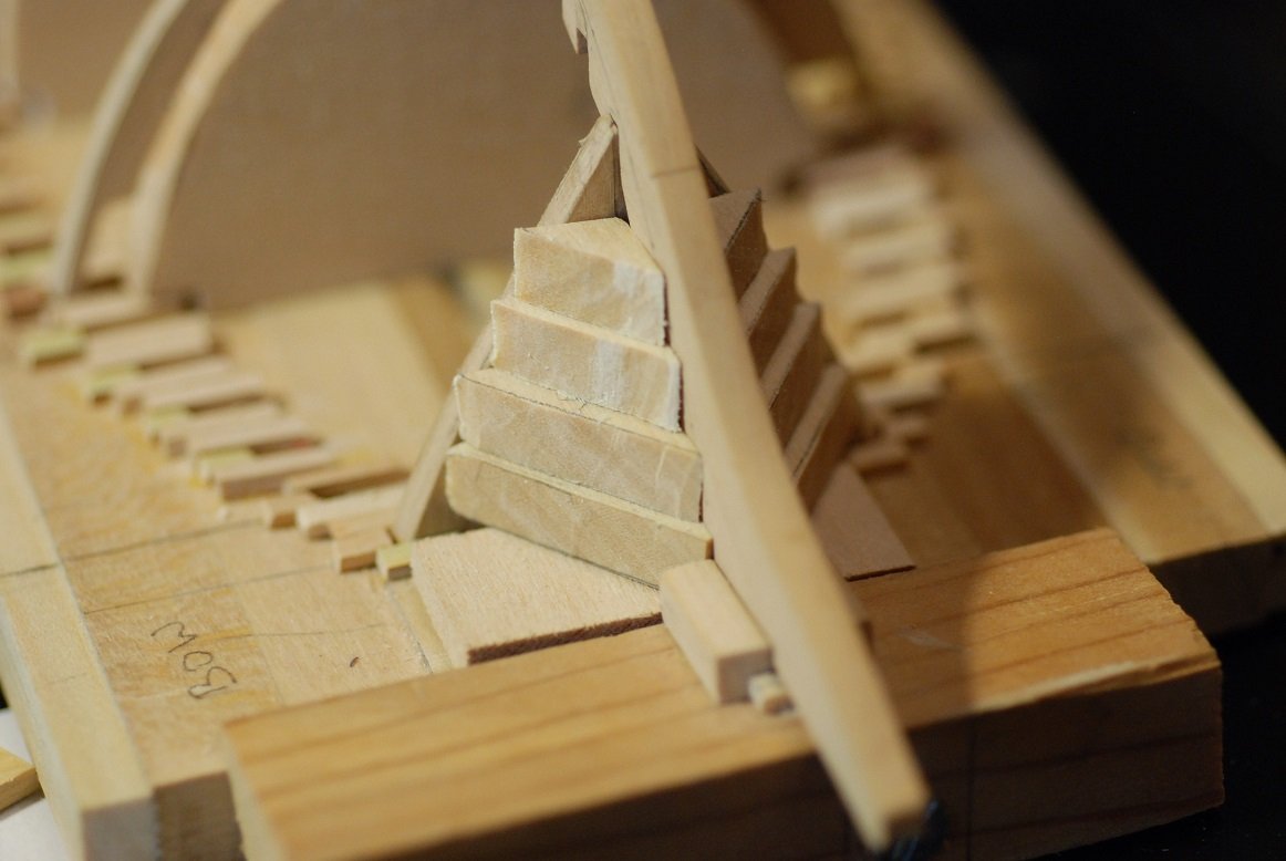
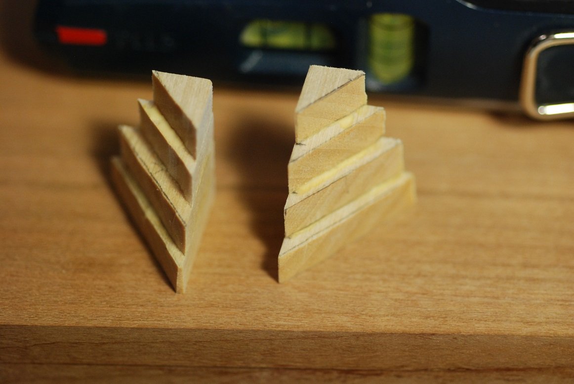
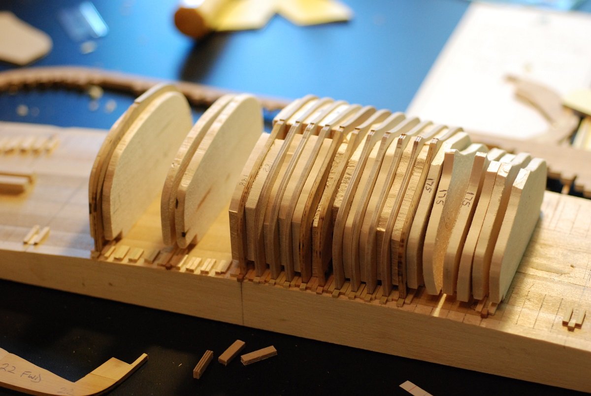
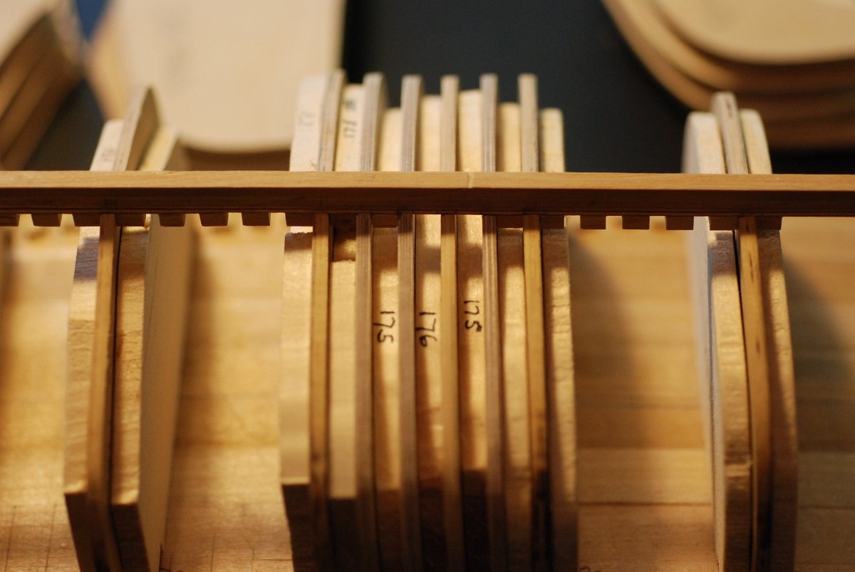
As of early July, this is about where things stood. All frames have been adjusted in height to bring the waterline into alignment. As a bonus, this photo shows four trial frames I didn’t use, but kept around. They have been cut to the molded dimensions suggested by Jaager in a previous post. And they sure look fragile. Fortunately they are sturdy for their size; some are made out of Baltic birch plywood, others are made of the laminates of boxwood I put a lot of effort into creating. At this time, I find myself very tempted to go ahead and cut all the frames to their true-to-life dimensions, but I have a few things to do first before we reach the point of making that decision. So with all the frames in place, I am almost ready to begin fairing the shape of the frames. But first I need to create a bow filler block, and at the same time as doing this and starting fairing, I need to finish carving a rabbet into the keel. The rabbet so far has been carved along the straight portions of the keel, but not extended into the stem nor into the deadwood. 3/16” thickness basswood sheets were cut into triangle shapes so that the edges corresponded to the shape of the first frame along the back edge, and along the forward edge the dimension was determined by the bearding line. I did not take the stack all the way to the apex of the first frame. These were then glued up. They were attached to a base block so they could be secured in the vise grip, then a chisel was used to smooth off the steps. In this step, the filler blocks are adhered to one another to make sure their shapes matched. The space adjacent to the first frame was prepared by installing a vertical piece in the centerline to support the first frame. It is narrow enough to accommodate the two filler blocks placed adjacent to it. Some basswood sheet was also attached to the baseboard to support the filler blocks from below. Filler block is in place, and now the shape of the stem rabbet is being worked out. I used a 1/8” chisel to work out the groove. The baseboard was starting to get in the way of my efforts to cut the rabbet. So I cut away a portion of the baseboard with a coping saw so I could get into the area more easily. This baseboard is a very dynamic structure, as it turns out. Also in preparation for carving the rabbet and for fairing, I had to secure the first frame a little better so it wouldn’t move around so much. There was a gap between the first frame and the margins of its slot, so this was filled in with a thin wood strip. Like so. Then the glue and excess wood was trimmed away. I am stopping here even though I could post more. But I am liking the idea of shorter posts. Trying to limit myself to no more than 15 images per post. Next up will be finishing the rabbet, then moving on to fairing.


-
Just so you know, your Mon Mothma paraphrase was not lost on this reader!
- 221 replies
-
- 1
-

-
- queen anne barge
- Syren Ship Model Company
- (and 1 more)
-
Druxey, exactly right. I am now looking at how to build the stern framing on my project. All I can do is look at one piece of wood in the plans and say "build that", then put it in place, and figure out where to go from there... Meddo, looks good!
- 221 replies
-
- 2
-
-
- queen anne barge
- Syren Ship Model Company
- (and 1 more)
-
Dave, glad to have you following along. Each of those passenger schooners is quite beautiful, and worthy of modeling. I always have liked modeling contemporary vessels since it makes the research easier. Jaager, I have a question about your figures from Meade, if you happen to be looking at this again. The "Moulded at cutting down", is that a vertically oriented dimension where the frame meets the keel? I may message you this question too.
-
Wow, planking at this scale using clinker planking is really impressive. It's enough of a challenge at full scale. What are you using for glue? I figure you are gluing each plank along both its rabbet joint side as well as where it touches each bulkhead?
-
Thanks Keith, ordered and on its way! JD
-
Yeah Keith, I may be in the market for something a little nicer.
-
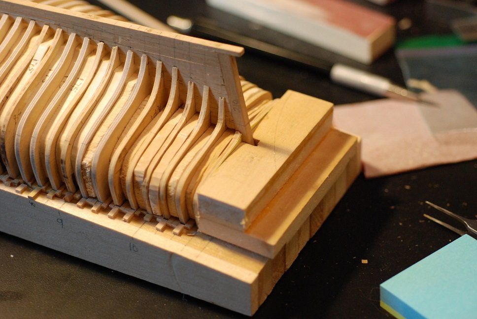
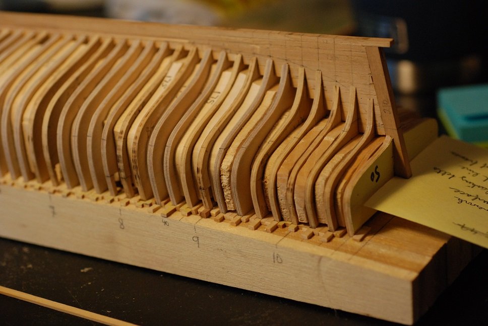
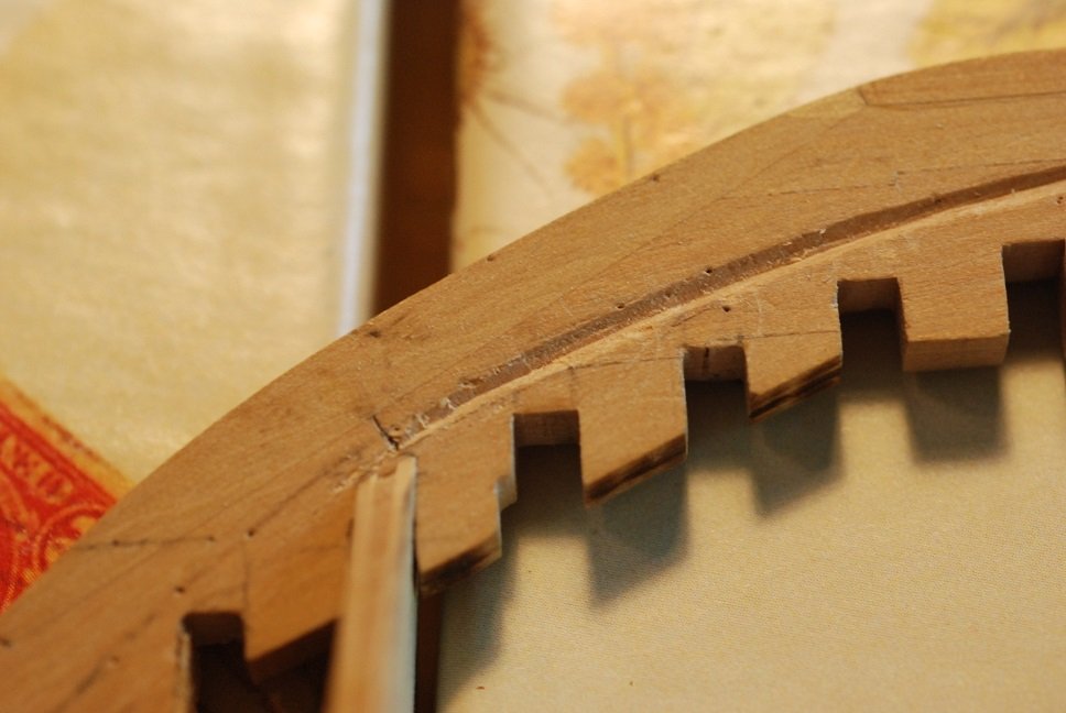
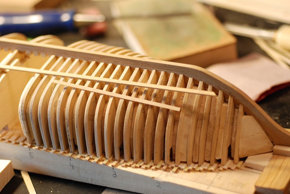
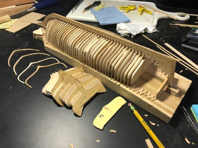
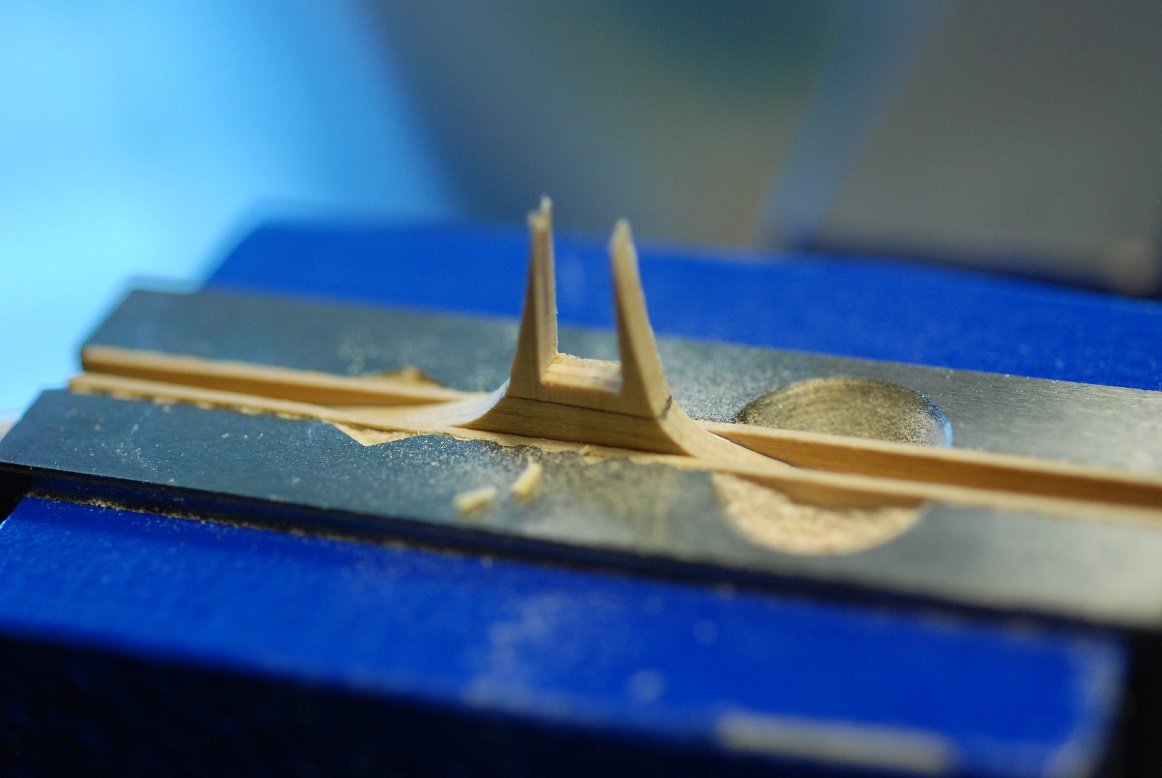
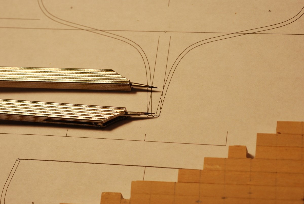
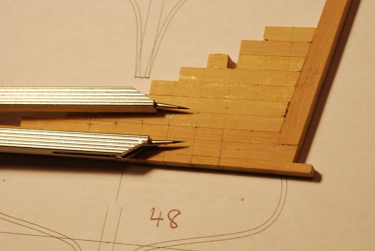
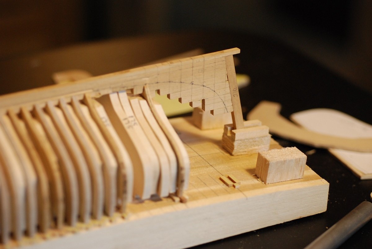
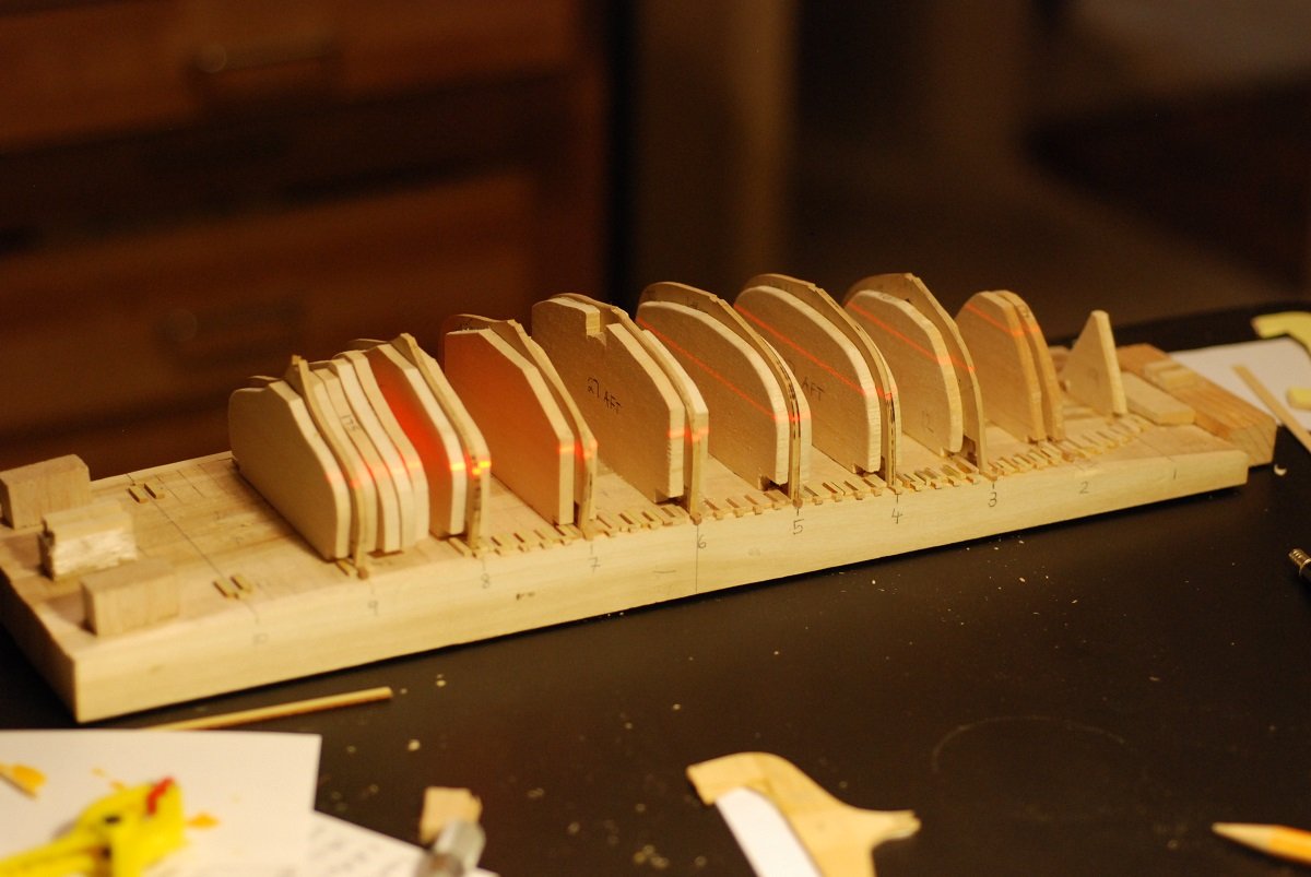
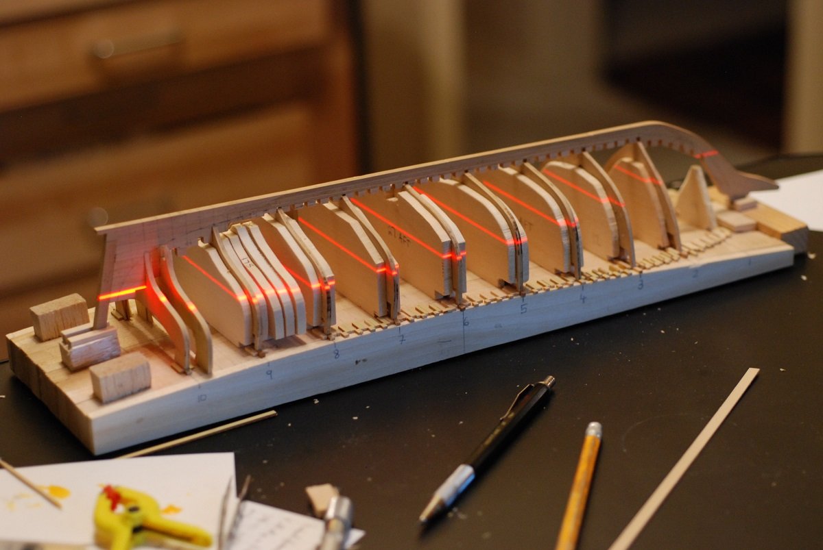
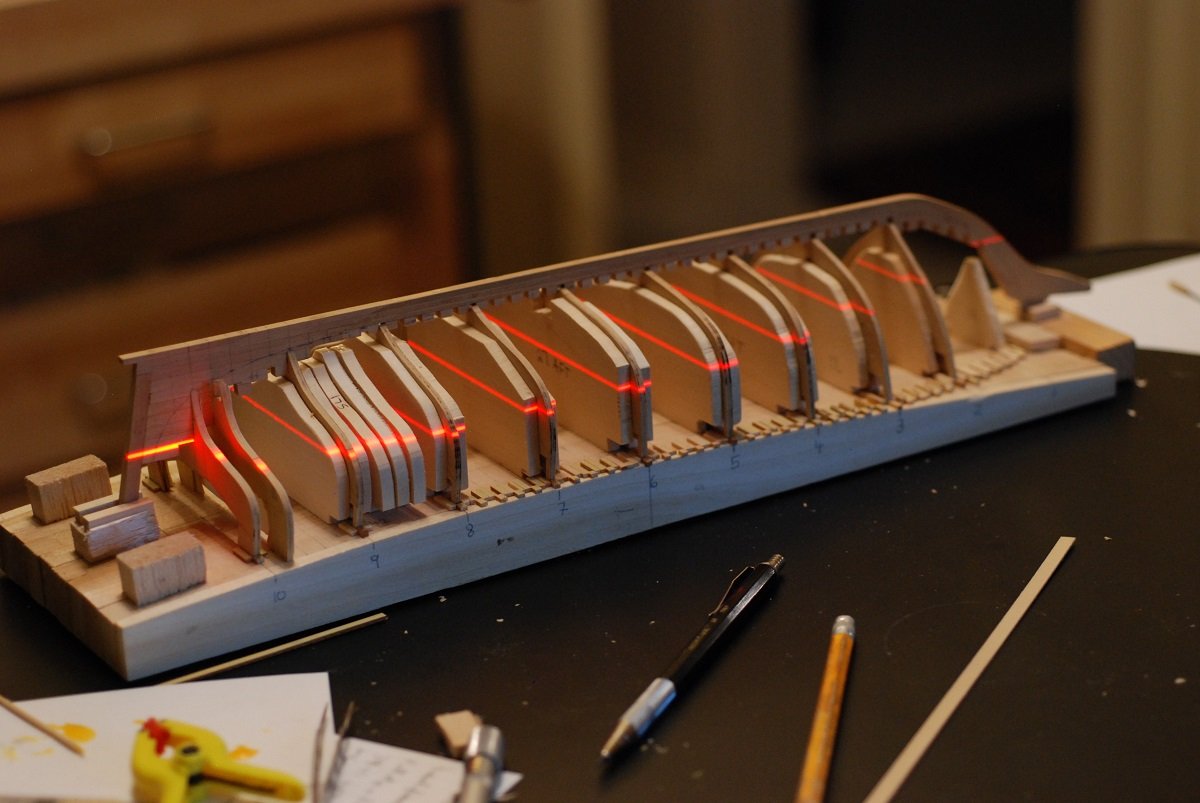
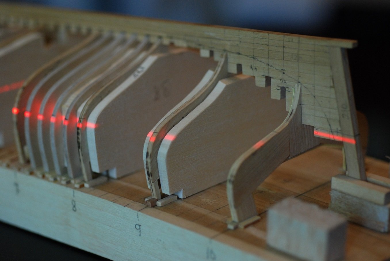
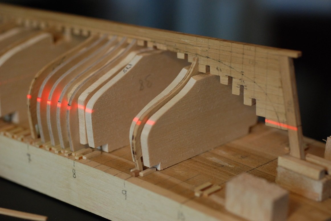
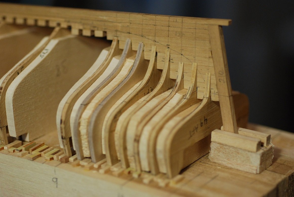
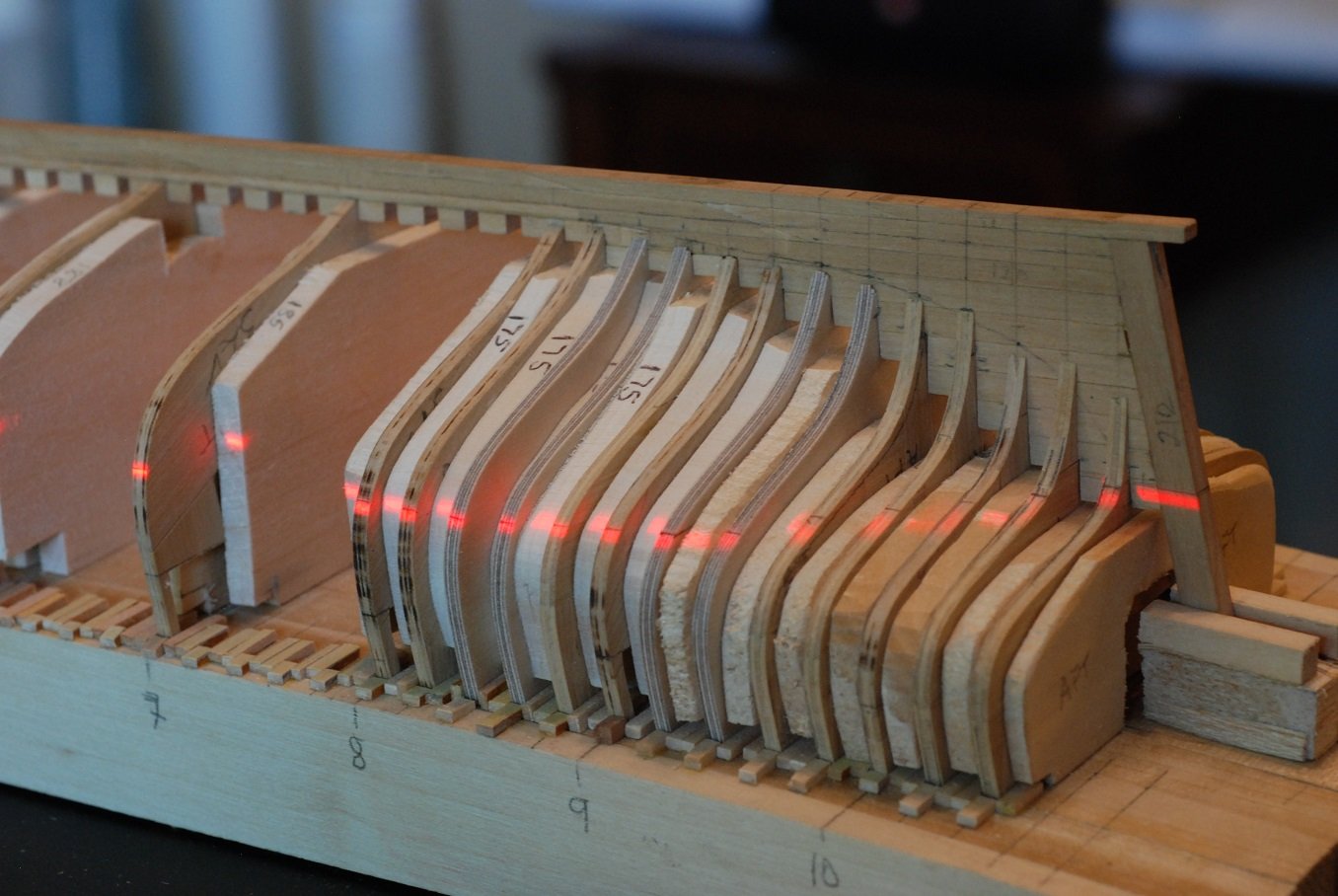
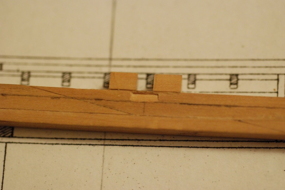
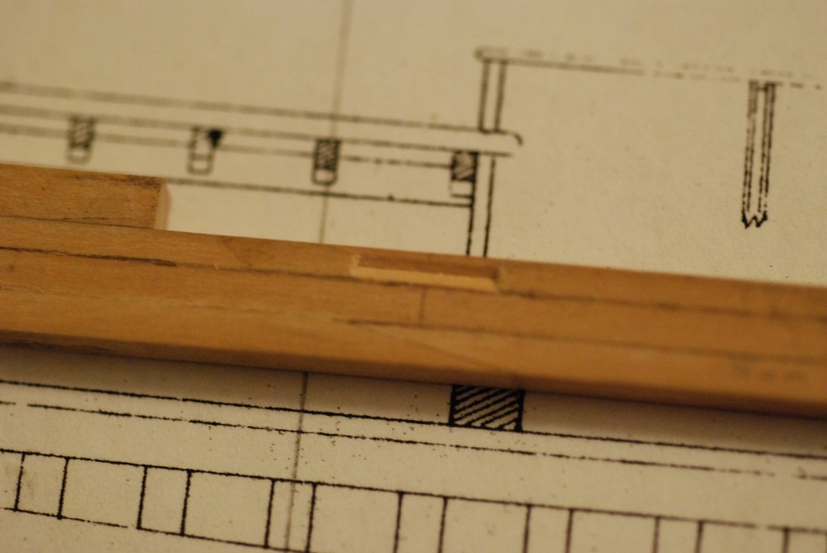
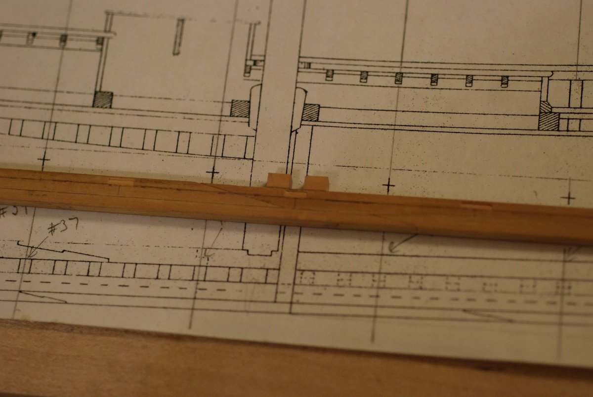
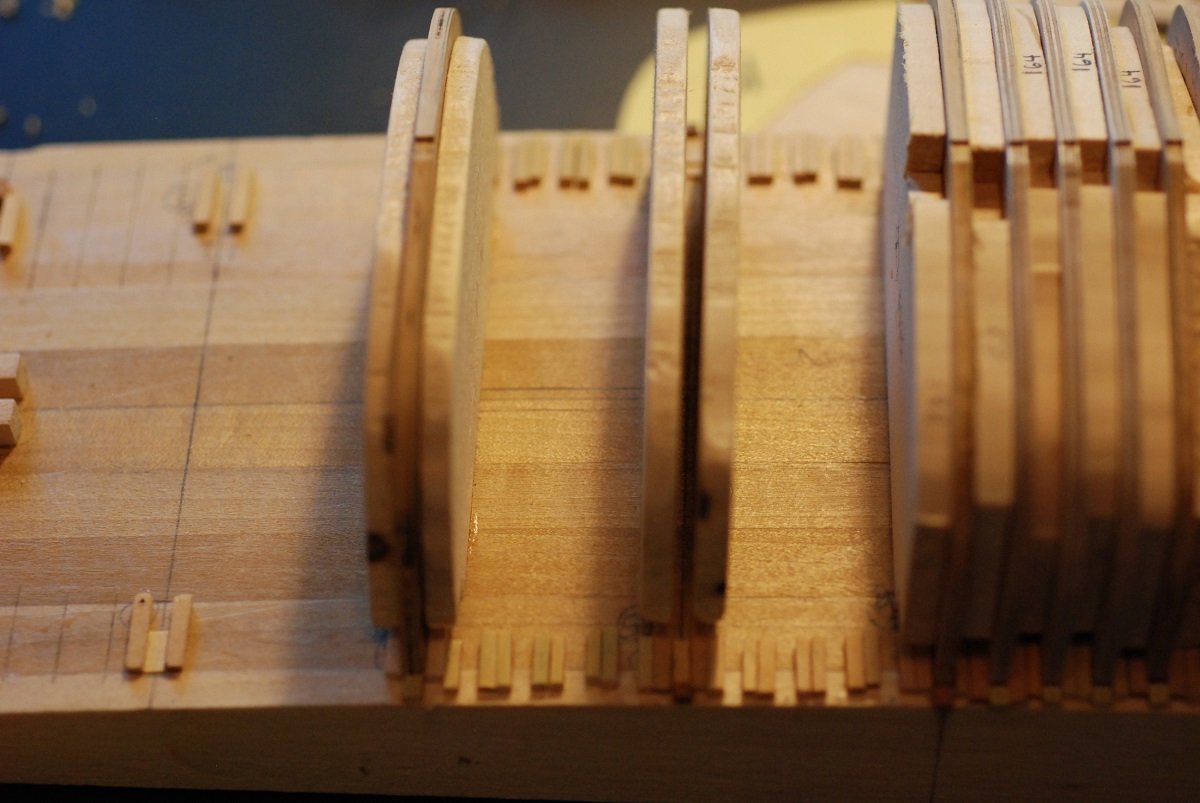
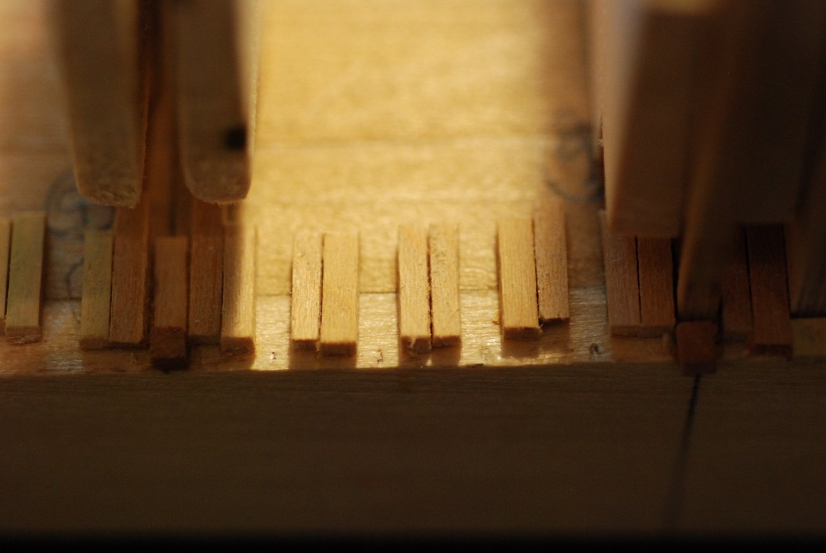
So things seem to be moving along nicely, as long as we are talking about the frames that are relatively midships in location. In order to proceed into the stern, it’s time to build up the deadwood. I cut segments roughly corresponding to the pieces indicated on the plans. The miter cutting capability of the Byrnes table saw came in handy for making sure the deadwood pieces articulated correctly with the sternpost. Now everything is glued in place. I marked the locations of the frame stations by marking the bottom of the keel, then extending lines upward from the keel through the deadwood pieces. This image shows one of the frame slots being cut out. Also in the image is a small compass that is from an old set of drafting tools I inherited from my mom. The tools were made by Staedtler in Germany; I don’t know how old they are but were used by my uncle in the 1950s. As stated in a previous post, the articulation between the keel/rabbet and the individual frames is important to get right, because this will determine how high or low a frame will sit with respect to the keel. It will impact the fairness of the hull all the way from the keel to the sheer. Fortunately, for the midship frames, this articulation is pretty easy to get right since the rabbet doesn’t change much for a fair distance fore and aft. So the depth of the notch I cut in each frame is relatively constant. This frame is starting to get toward the stern, and the frame shape at the keel becomes much more vertically oriented. Even further toward the stern, and the frame shape really tapers off gradually towards its bottom edge. So how deep do I cut the notch? How do I make sure the stern frames are positioned so they are not too high or low? My printouts of each frame include the planking thickness, and show how it articulates with the keel. Theoretically, the distance marked with the caliper above should correspond to the distance from the rabbet line to the bottom of the frame at this particular station, at one of its surfaces anyway. This particular image is of the larger side of this frame, so this more precisely would be the distance between the forward corner of the bottom of this frame to the rabbet’s edge. And the edge of the rabbet is fortunately clearly defined on the plans. So here I am measuring up from the rabbet line to the point where the bottom edge of that particular frame should end up. For the more experienced builders out there, I apologize in advance for my denseness. It eventually occurred to me (but was already evident to those of you with experience) that the bottom edge of the frames should outline the bearding line of the rabbet, and that line is definitely not depicted on the plans. But I should be able to get the bearding line from my 3D model, by taking a section of the hull’s shape using a plane perpendicular to the centerline, but shifted slightly from the centerline so that it corresponds to the outer surface of the keel. Manipulating the 3D model in this way gives us this curve, which is printed with the outer shape of the keel also in the image for guidance, so I could use it as a pattern. The pattern was transferred to the keel, resulting in this curve. So I thought I had solved the problem. Until I thought about it some more, especially after cutting notches into some of these stern frames and realizing how variable the shape of the bottom edges of these frames could be. They literally taper down to nothing. In the case of this frame, the result is that one side of the frame adjacent to the notch is significantly higher than the other side. Can I really rely on the articulation of this feather edge with the bearding line? If not, what can I use? And how about a frame like this one? Once again I indulge the patience of those of us builders that have more experience with these issues. Of course, as they know, the solution is to use the waterline as the reference point. And the location of the waterline is indicated on every frame shape that is generated from my 3D model. I spent a lot of time reprinting templates and affixing them to the frames I had previously trimmed to the proper shape, then transferring the waterline to the edges of those frames. I then set up the laser level on boards of appropriate thickness to bring the laser line to the level of the waterline. Of course, the laser line has width, so the waterline pencil marks on the frames and keel were brought to the top edge of the laser line. Many of the stern frames had to be redone in order to bring the waterline to the correct height while still preserving the articulation of the bottom of the frames with the keel/rabbet. In this image, the frames at station 8 and 9 are too high (well, low, actually, below the laser line if the hull is inverted upright), and the waterline mark on the sternpost is also high. This is probably because the laser line hasn’t been properly leveled yet. After adjusting the level of the laser, a consistent waterline is laid out. Here are the eight frames that are located right where the bearding line sweeps upward toward the transom. You can see how the heels of the frames are totally varied in their position, and how inconsistently they relate to the bearding line. But this should come out in the wash when it’s time for planking, as long as I carve the rabbet correctly. 13 frames are now lined up in position, and you can see how the laser denotes the waterline pretty fairly. A lot more fairly than if I had left it to other means. Glad I finally figured out using the waterline as a reference point. I spent some extra time getting the basswood filling blocks between each frame to be of the right thickness for its individual spot. These frames are going to need a lot of support when it comes time for fairing with a sanding strip.

-
Just as an aside, while I am between posts, I want to share a Youtube channel of an Englishman working up in the Pacific Northwest who is completely rebuilding a 1910 gaff cutter designed by Albert Strange, called Tally Ho. He has been at this for about 3 years. His videos are excellent, and he so completely describes and depicts traditional boatbuilding techniques that are immediately applicable to anyone building a boat model that intends to duplicate the way the original boat was actually built. I imagine that some of you are already familiar with his work. https://www.youtube.com/channel/UCg-_lYeV8hBnDSay7nmphUA/videos Watch out! It's easy to get sucked in. JD
-
The floral trailboard at the bow, did it need to have any contouring of its backside to get it to lie fairly against the bow planking?
- 221 replies
-
- 1
-
-
- queen anne barge
- Syren Ship Model Company
- (and 1 more)
-
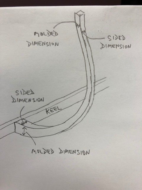
Hi Phil, thanks for the bibliography. More resources to pursue! Shout out to the USS Oklahoma City from your avatar. I agree the terminology can be confusing, and describing molded vs sided measurements can defy easy explanation. Which is why I remain so surprised that there are not readily available drawings depicting the difference, not even in Chapelle's Boatbuilding. Glad my drawing has been helpful. Jaager, thanks for the updated dimensions. Ultimately we will see how these compare to actual measurements, which I will obtain sometime in August or September when I revisit the Mary Day in Camden. Michael, good to see you. Thanks for following!
-
So length on deck is 83 feet, beam of 23 feet, max draught is 7 feet. I will be interested to see what measurements your source provides. Thanks in advance, Jaager!
-
Jaager, that is great! The length on deck is 83 feet. When I get home from work today I will send you the beam and draught measurements.
-
Since I can't find any pictures illustrating molded vs sided dimensions... I hope that helps!
-
Druxey, I could probably get a used microtome from my colleagues in pathology, now that I think about it... Vaddoc, I am referring to the molded dimensions of a frame, which is the width of a frame as you look at it from the bow or stern. It's the dimension of the frame from its outer surface where the planks contact it, to its inner surface that is visible from inside the boat. Boatbuilders refer to the molded dimension and the sided dimension of frames, where the sided dimension represents what we might call the thickness of the frame (its fore-and-aft dimension). Whereas the sided dimension of a frame is usually constant, the molded dimension of a given frame is greatest at the level of the keel and becomes thinner as the frame approaches deck level. I can't believe that when I search for online images demonstrating these terms, that nothing pertaining to boatbuilding comes up!
-
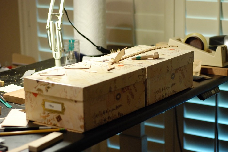
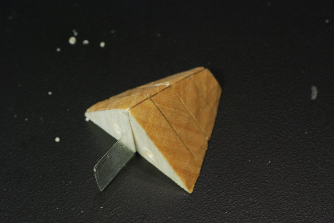
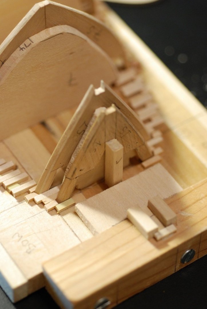
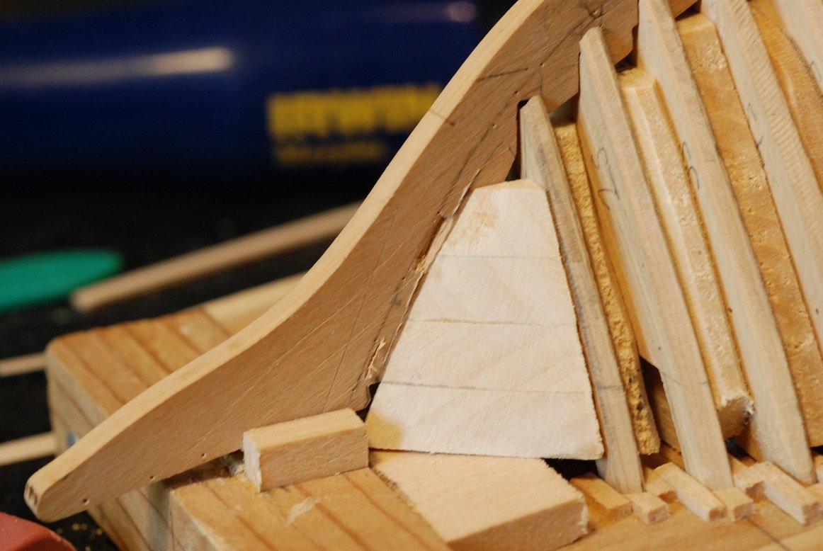
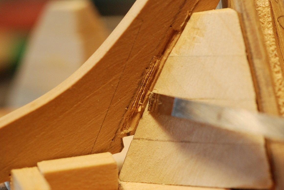
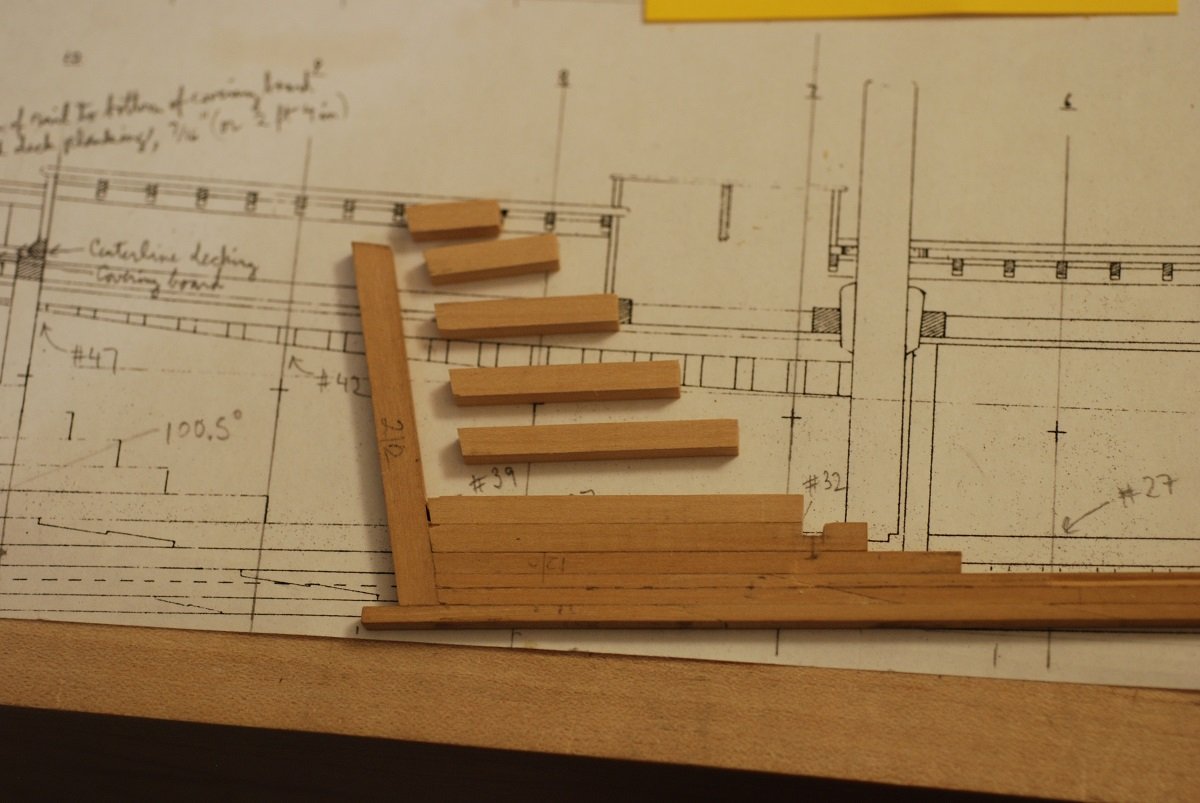
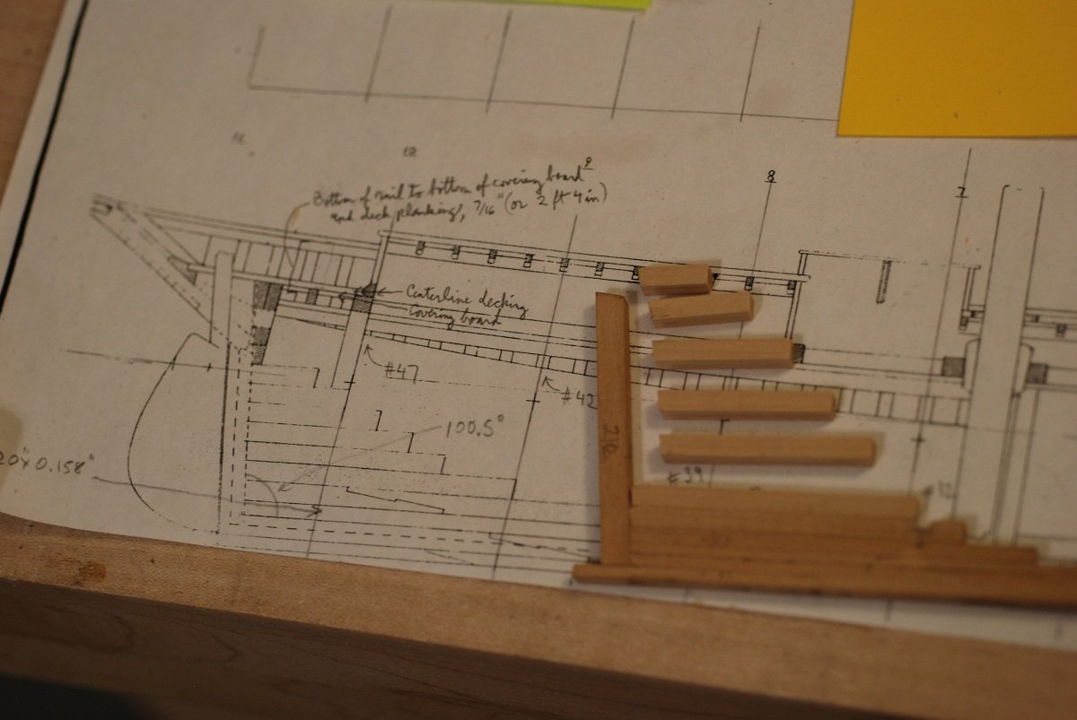
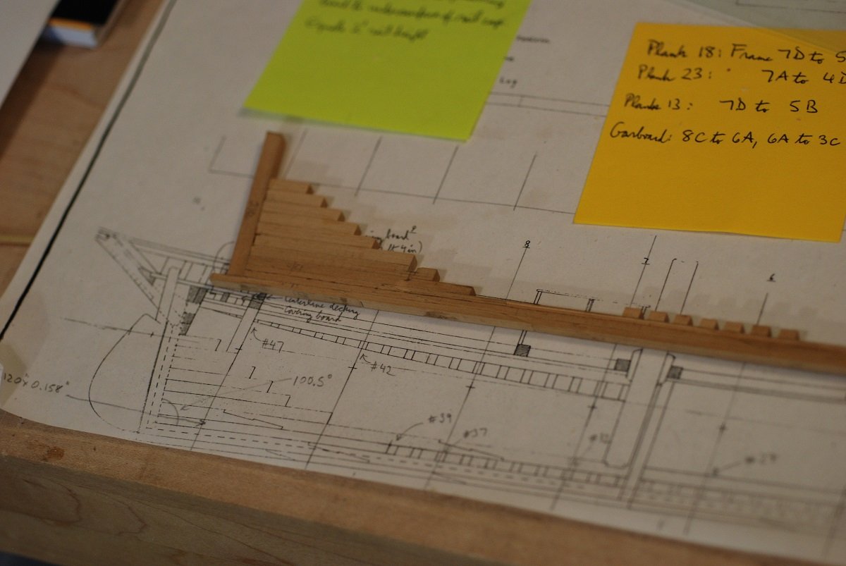
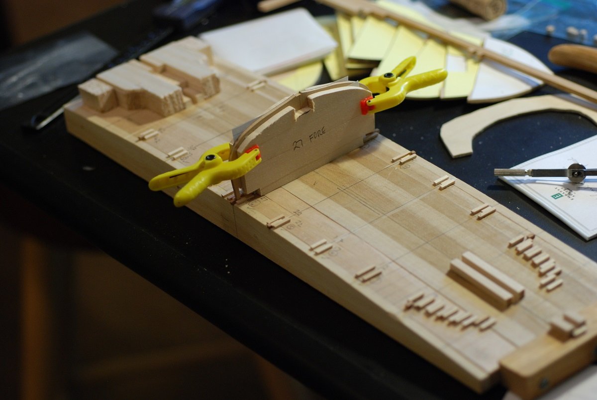
In my last two posts, I included an image that represented a significant jump ahead in the work on the model. Now I will fill in some of the blanks on how I came to the point of having so many frames filled in on the model’s baseboard. I could theoretically have omitted the rabbet from this model, and created a garboard plank with an edge that just abuts the keel. But given the Christmas craft project I completed and showed in the last post, I certainly now feel comfortable with the idea of carving out a small rabbet into the edge of the keel. I think it also will make the installation of the planking easier, and also some degree of rabbet carving would be absolutely necessary in the area of the deadwood. In the month of February I got to visit the Rockland Apprenticeshop on the coast of Maine. There I watched an apprentice working on carving out the rabbet on a full size keel for a lobster boat they are constructing. At full scale, of course, when carving out a rabbet, you have the benefit of fully lofted rabbet lines, bearding lines, and apex lines. At my scale, though, all that is going to have to be eyeballed. So, I took a deep breath, and while holding a frame for a particular station against the keel using a jig, I laid out and started to cut small areas of the rabbet at a couple of different stations. I used a 3/64” thickness strip of wood as a simulated plank in order to check the depth of the rabbet and the interface between the edge of the plank and keel to make sure I wouldn’t have a gap. I now regret not having a picture of my jig for holding everything while I worked on it. In this picture I have carved out 3 different locations, which enabled me to carefully extend the rabbet between these locations. The process involved a lot of moving back and forth between the jig and the microscope, through which I monitored my carving. I did use some of the same micro-chisels that I constructed for the Christmas craft project I had just completed. Here I am starting to extend the rabbet into the stem. A long, straight segment of the rabbet in the midships area has been finished here. I stopped at this point and awaited further development of the stem and stern framing before working on the stem rabbet and the deadwood (which hasn’t been constructed yet). Next step was to solidify the job of the baseboard by installing guides for the placement of the station frames. I used basswood of approximately 3/16” thickness to create shapes that resembled the shape of the frames they would support, but smaller in size so as not to interfere with the future process of fairing the shape of the hull once all frames were in place. As these were put in place, they were of course checked against the keel to make sure that the frame remained vertical and articulated with the keel in the correct location. I believe this is station 6 (of ten). Station 7’s support pieces were installed in the same way. Then, between stations 6 and 7, the intervening frames were test fitted, with additional pieces of basswood of appropriate thickness to support each of them. In this photo, the sheets of paper are being used to leave some residual space adjacent to each frame, to reduce friction. The sheets of paper have been removed. A detail of the edges of the frames as they sit on the boards. Shims are being installed to ensure accurate location of the frames at the level of their bulwark stanchions. Some of the frames in the image are still unsupported. Others have their fore and aft shims installed, while the frames on the station lines have fore and aft shims as well as shims to restrain their transverse movement. Once I was happy with the frames’ positioning on the baseboard, the keel was brought in, and the filler blocks located between the foot of each frame were installed. Compared to the waterline, there is an upslope of 2 degrees as the keel moves toward the bow. So this angle had to be accounted for in order to make sure that the slots for the frames were oriented vertically. The miter gauge with the Byrnes table saw made this easy work. Just making sure that everything here is still staying vertical…this was a good way to make sure that the keel pieces between the frames were of the right length and that errors weren’t creeping in. Then it’s on to the next station and its support pieces. In the end, I think only the station frames will have these support pieces permanently installed. Here I am using the frames to draw out the shapes for the basswood support pieces that are put between the frames. Shims have been installed between these stations. Building up the sandwich that is going to make up the shape of the hull. At this point, I am opting to use boxwood for the frames in the midships and in the bow, and trying to confine the use of plywood to the aft part of the hull. That way, if I want to leave a part unplanked for display, the forward half of the ship will look authentic. If I opt to do that, the exposed frames will have to be trimmed to their actual molded dimensions rather than being solid bulkhead-type pieces of wood. More of the keel spacer pieces have been installed. Next up will be the deadwood, which will cause all sorts of questions to arise!
-
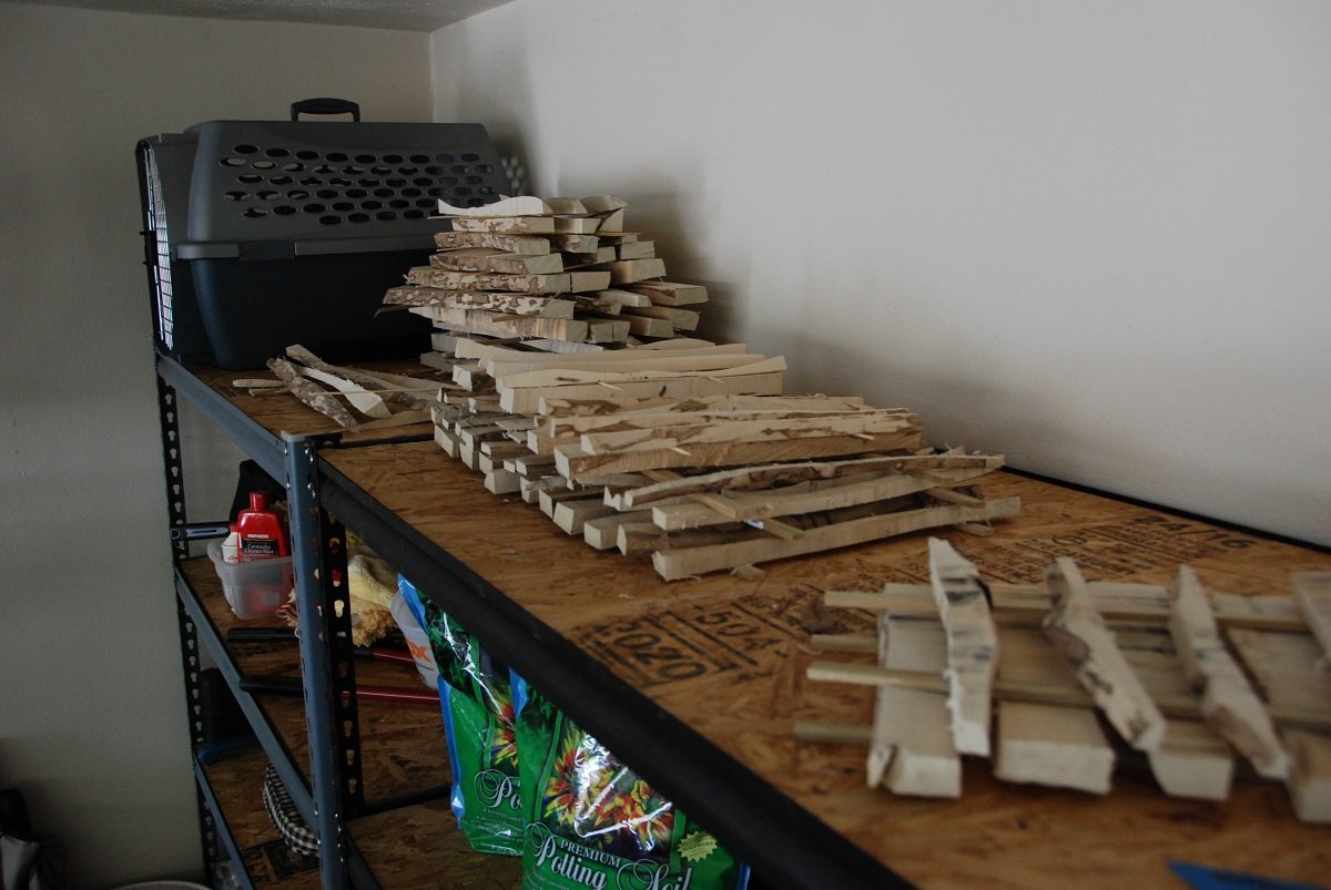
If only the rest of the world valued holly as much as we model builders do, I would be the richest man in Babylon! And I haven't even finished cutting up what I have...
-
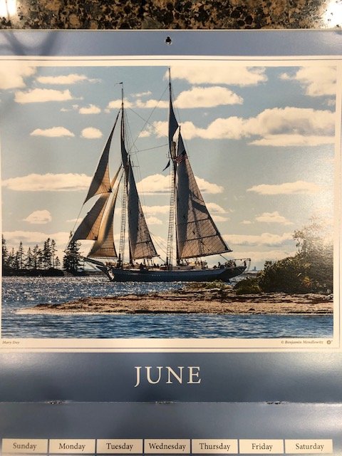
Those of you who have the Calendar of Wooden Boats by Benjamin Mendlowitz may have noticed that June 2020's cover girl is...the Mary Day!