jdbondy
-
Posts
341 -
Joined
-
Last visited
Content Type
Profiles
Forums
Gallery
Events
Everything posted by jdbondy
-
 Michael, I have been delinquent in following your build. Great work! When you made the homemade scraper, what kind of incredibly small file were you using to cut the desired shape into the scraper?
- 221 replies
-
- 2
-

-
- queen anne barge
- Syren Ship Model Company
- (and 1 more)
-
By the way, when you pull up my build log, is the entire build log on only two pages? Those seem like two awfully long pages compared to other peoples' posts.
-
I get lots of comments from visitors to the house. Definitely better than in the corner of the shop!
- 60 replies
-
- 1
-
-
- pride of baltimore ii
- Model Shipways
- (and 1 more)
-
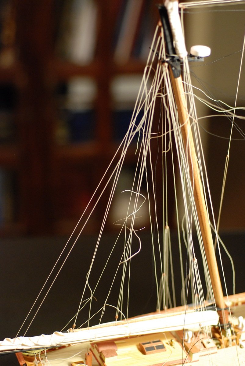
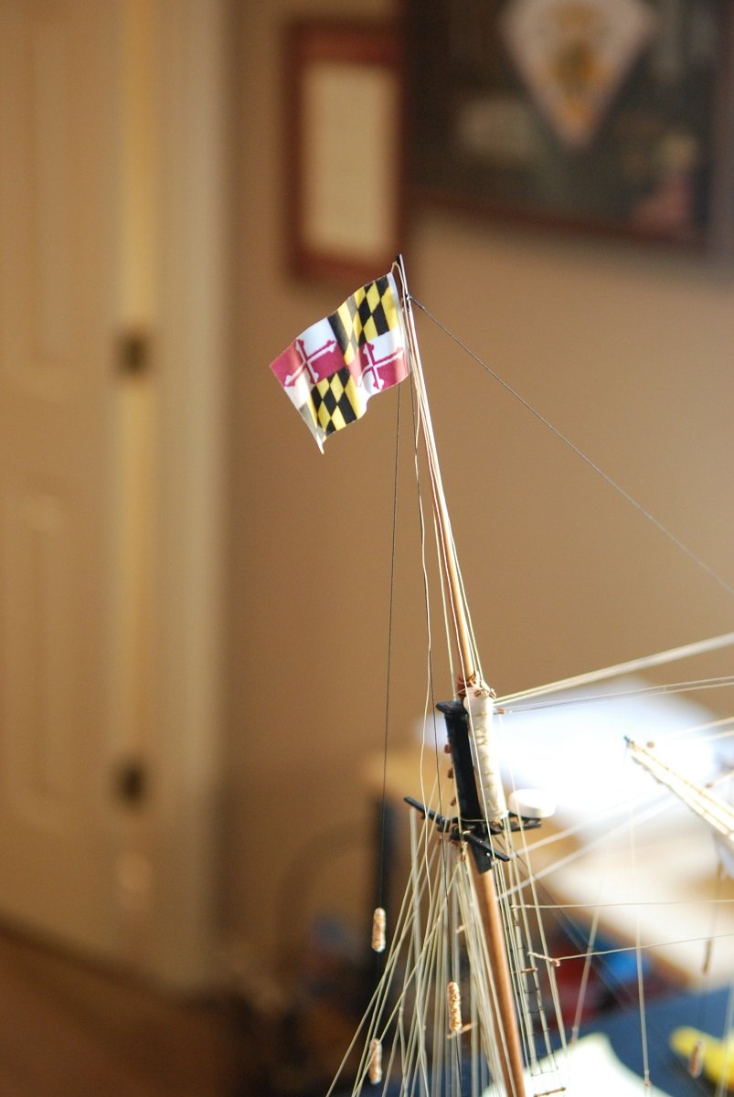
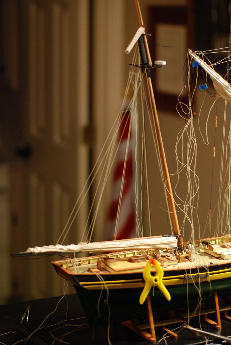
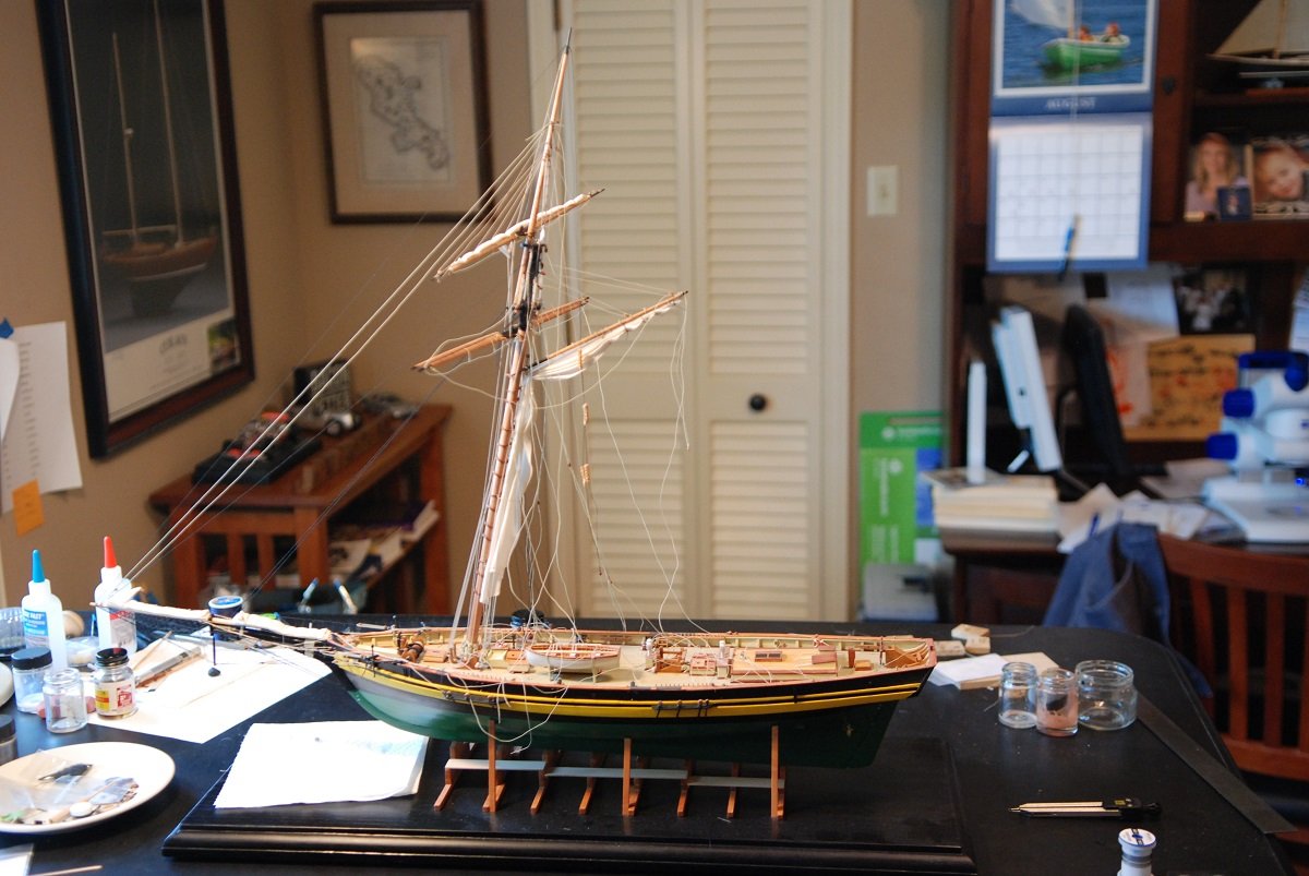
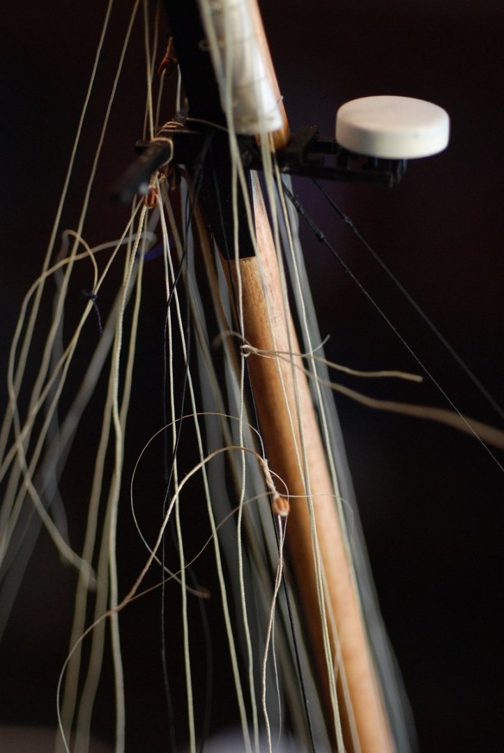
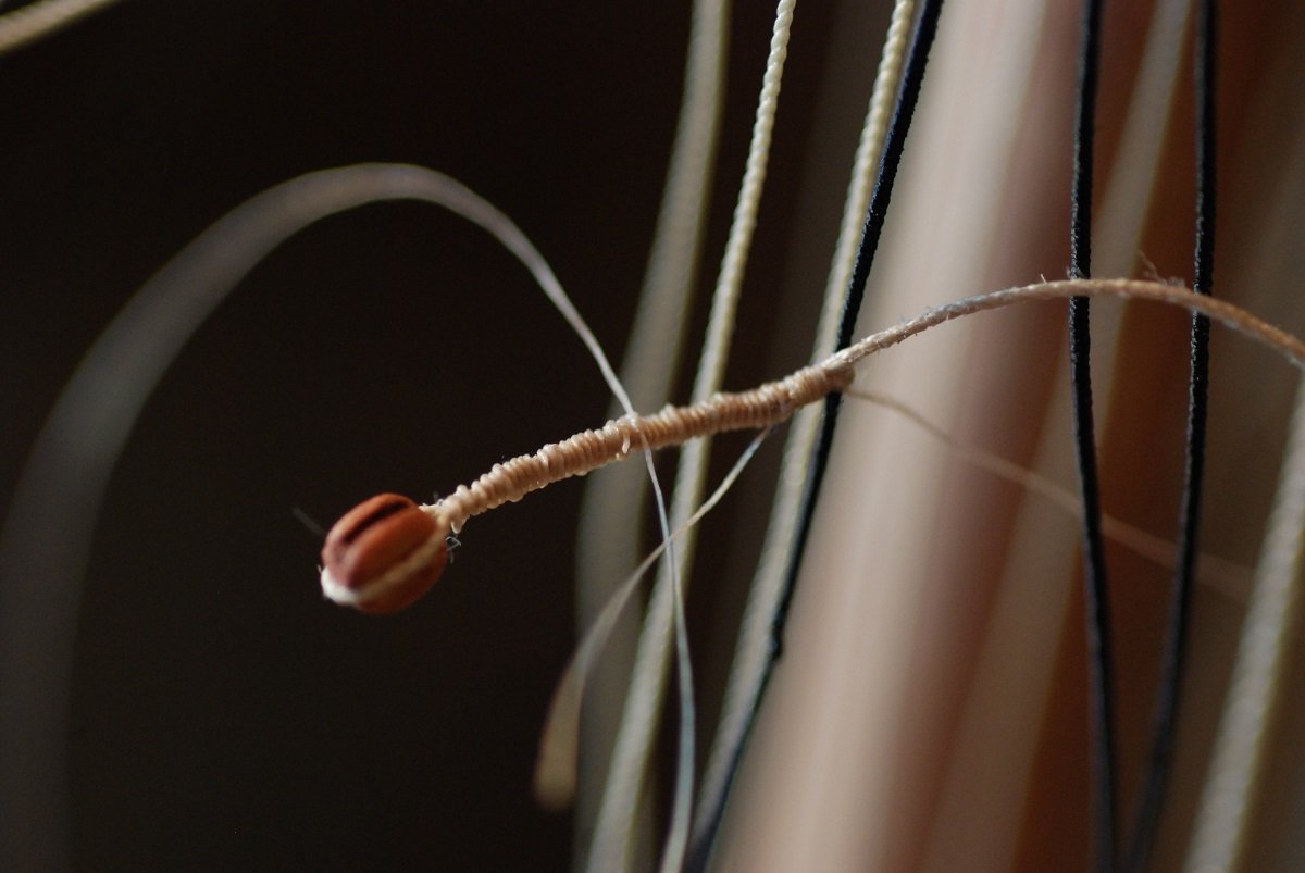
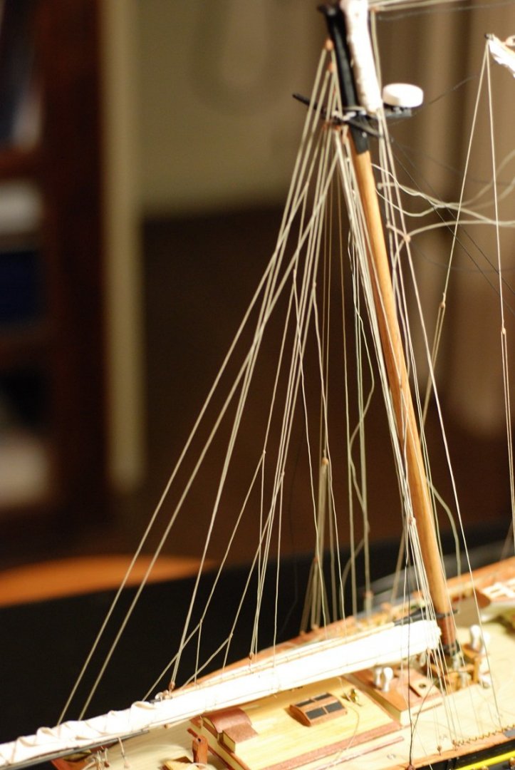
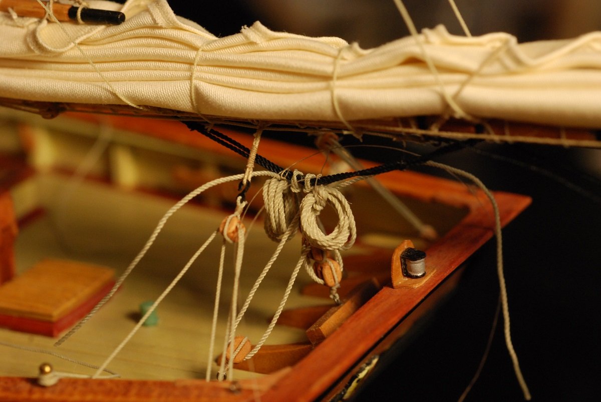
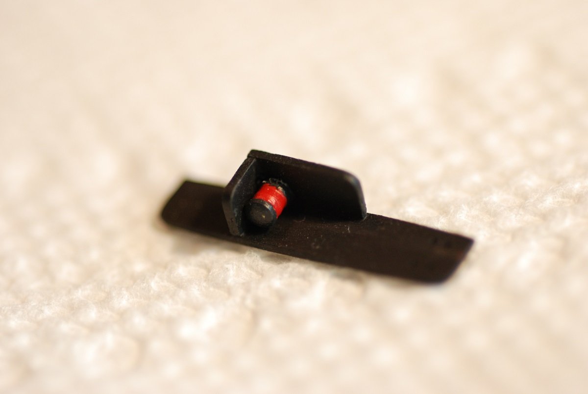
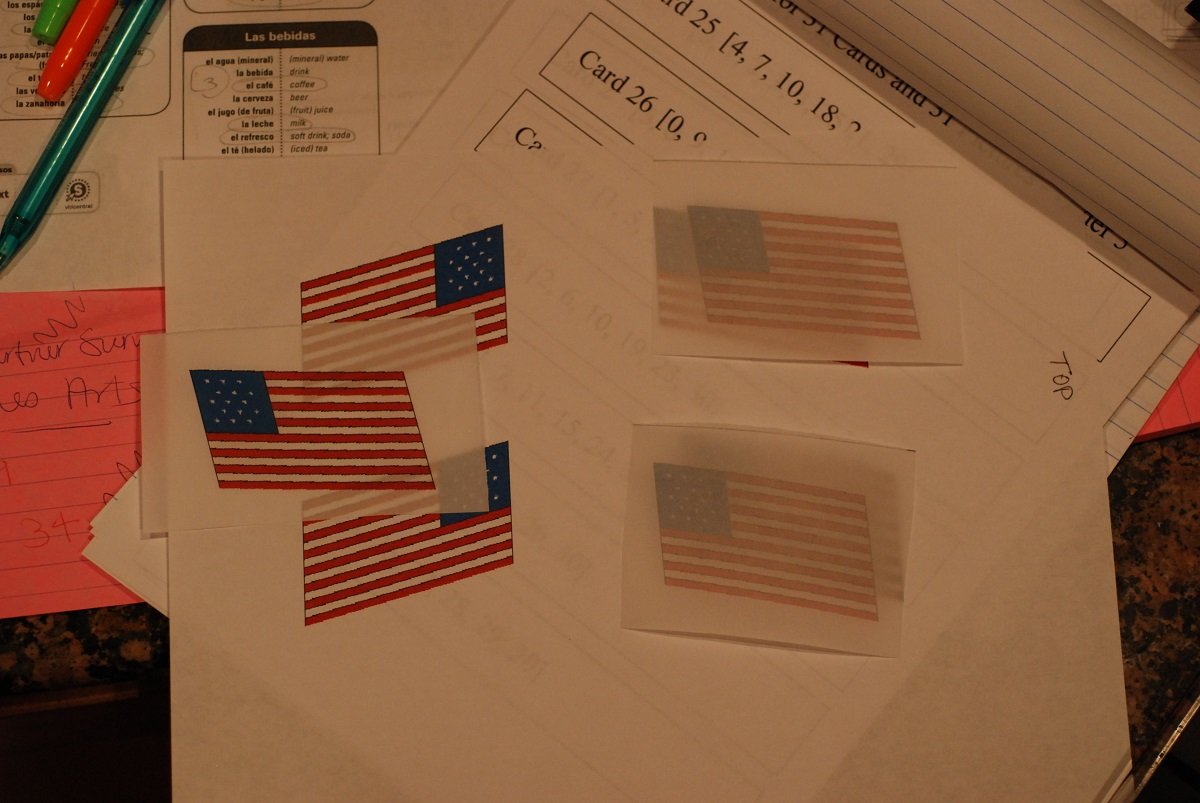
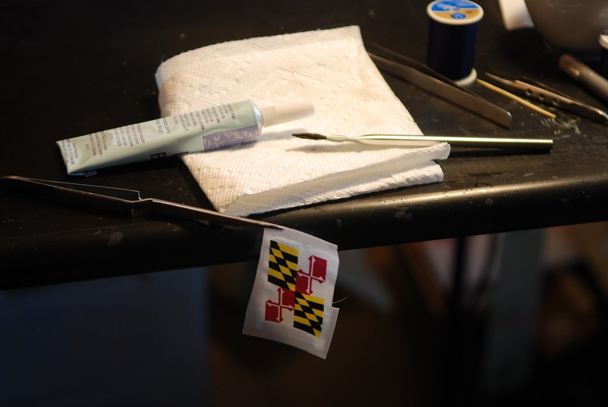
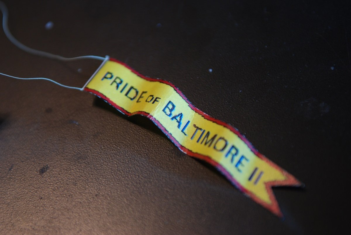
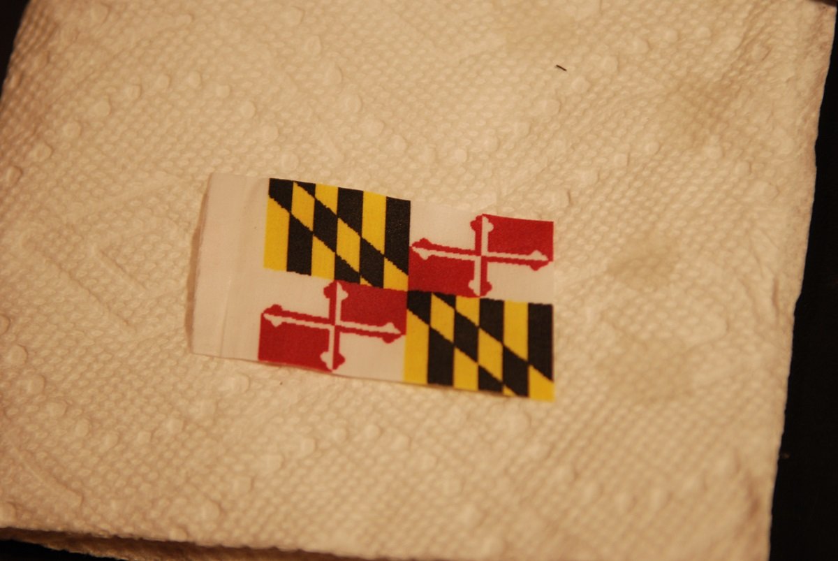
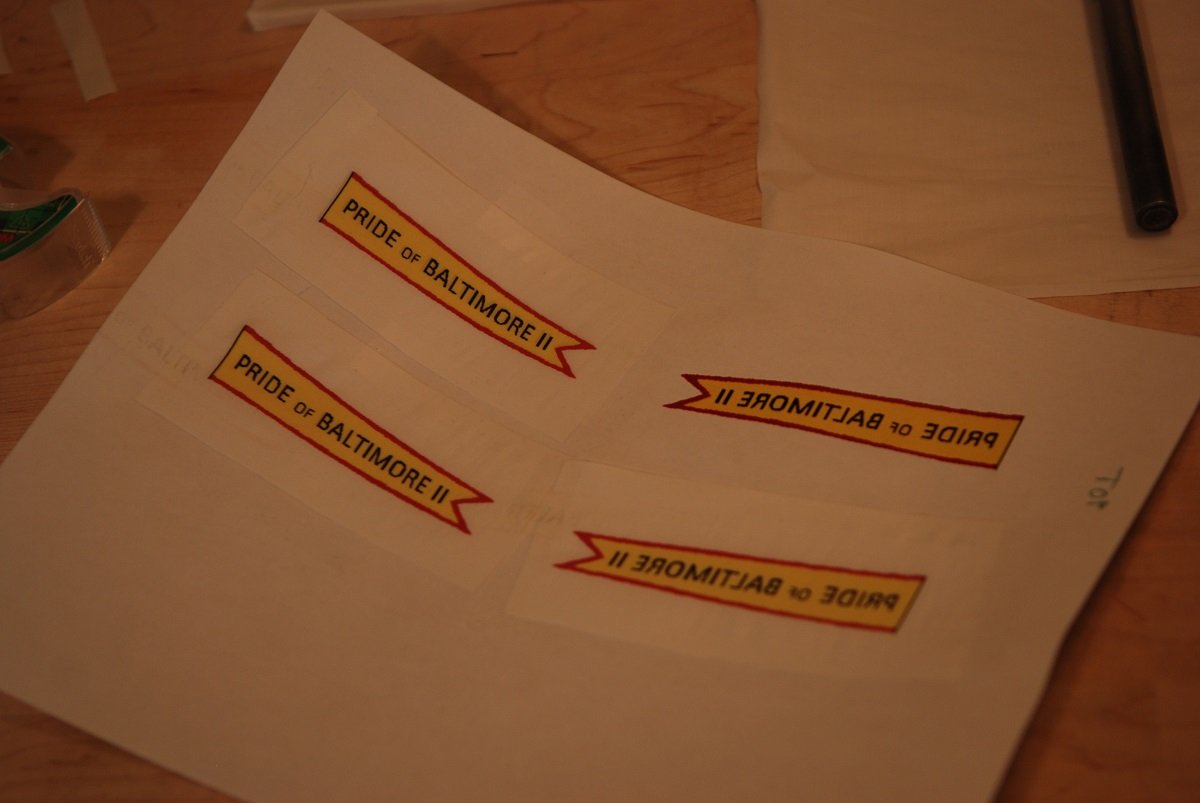
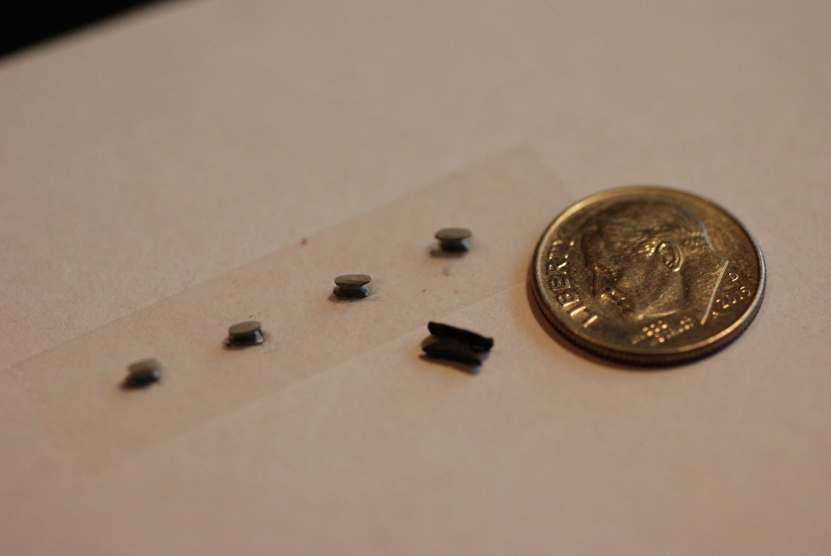
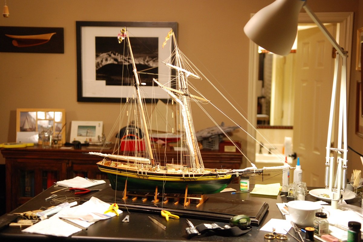
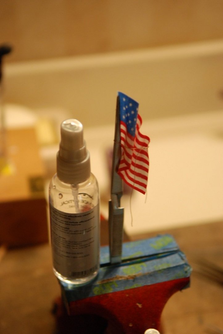
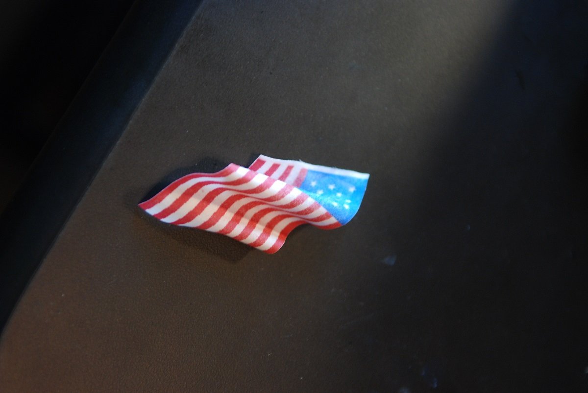
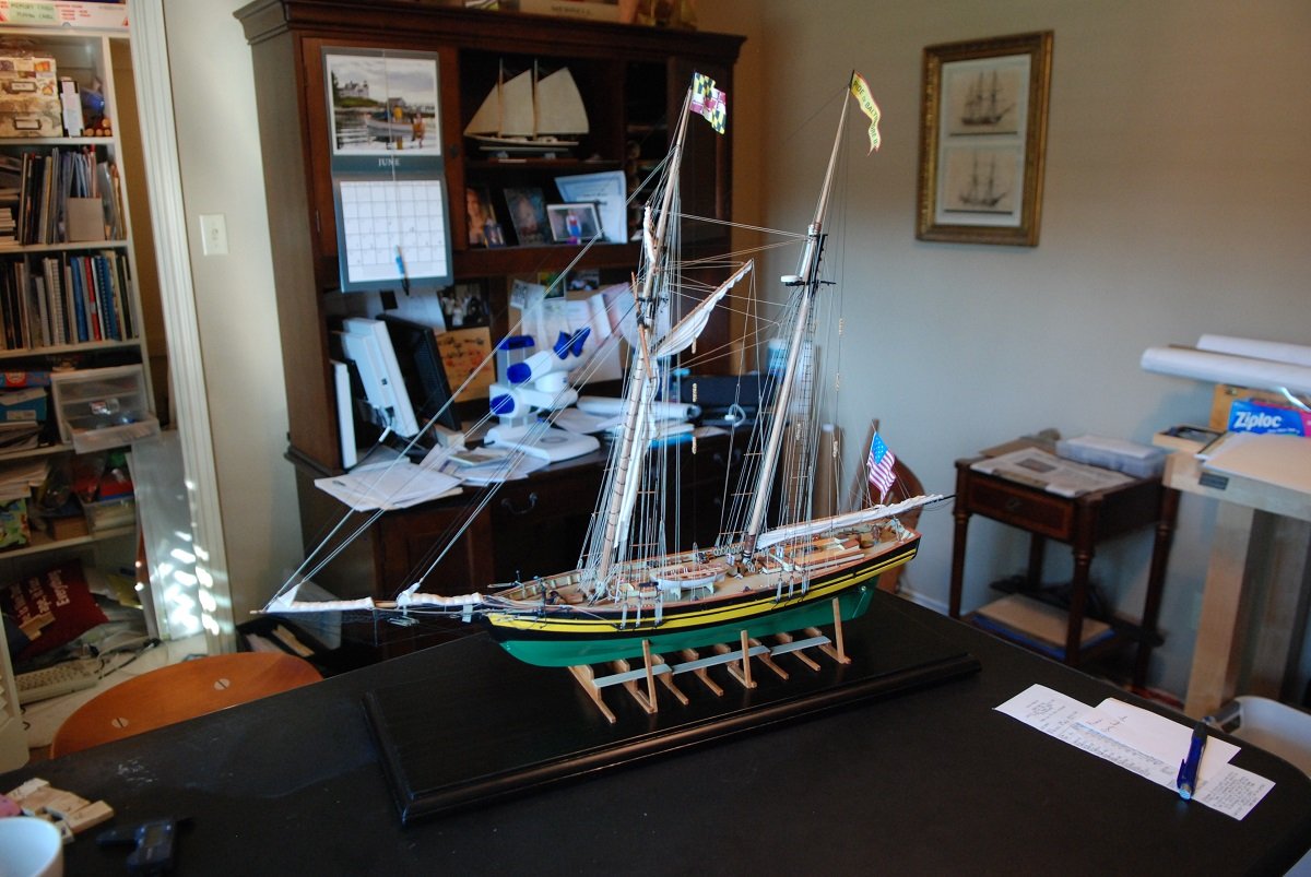
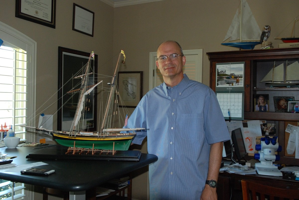
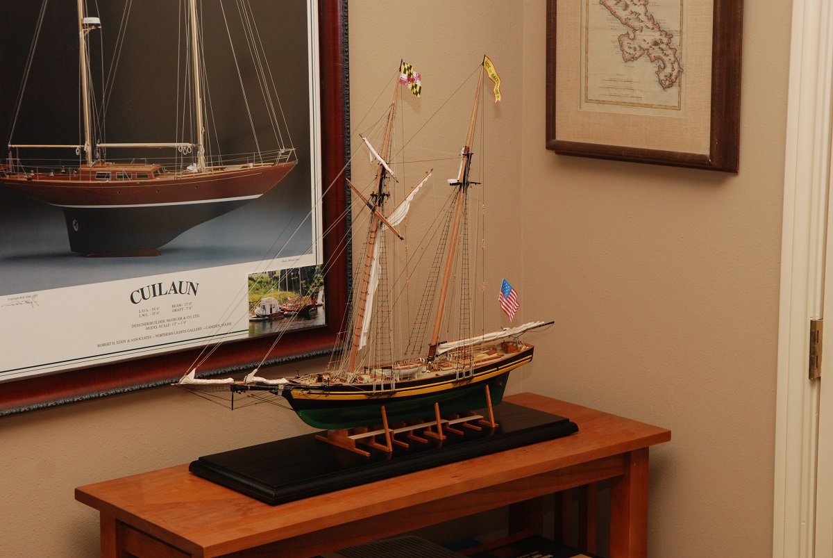
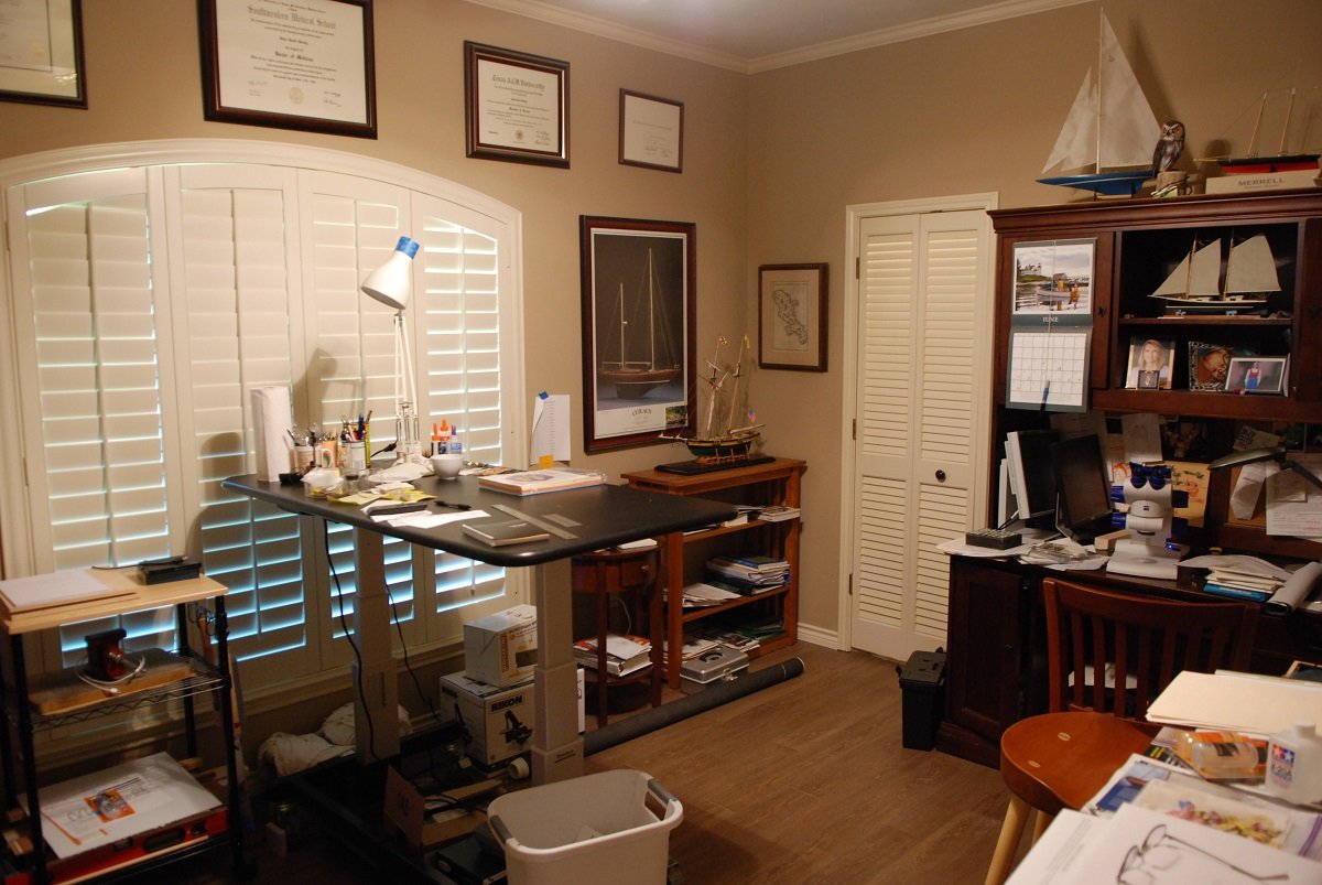
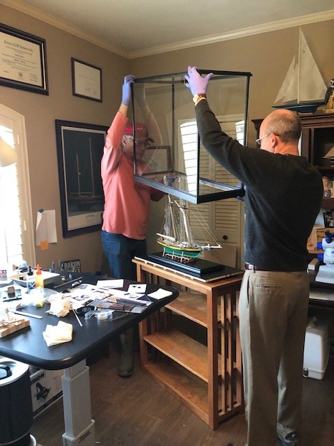
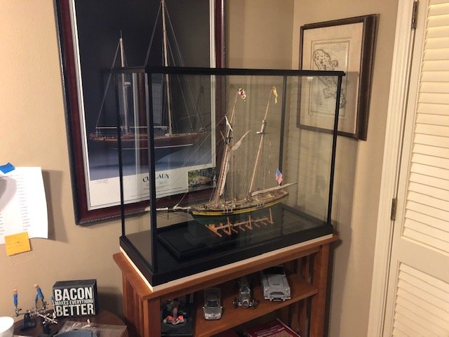
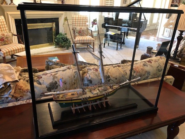
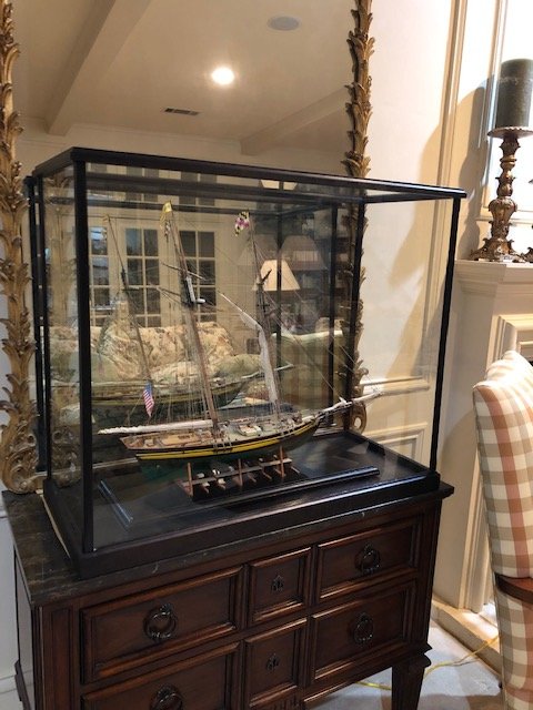
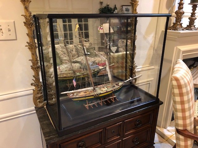
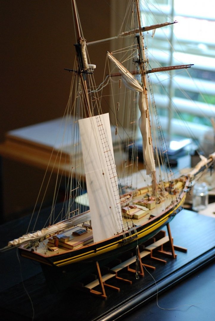
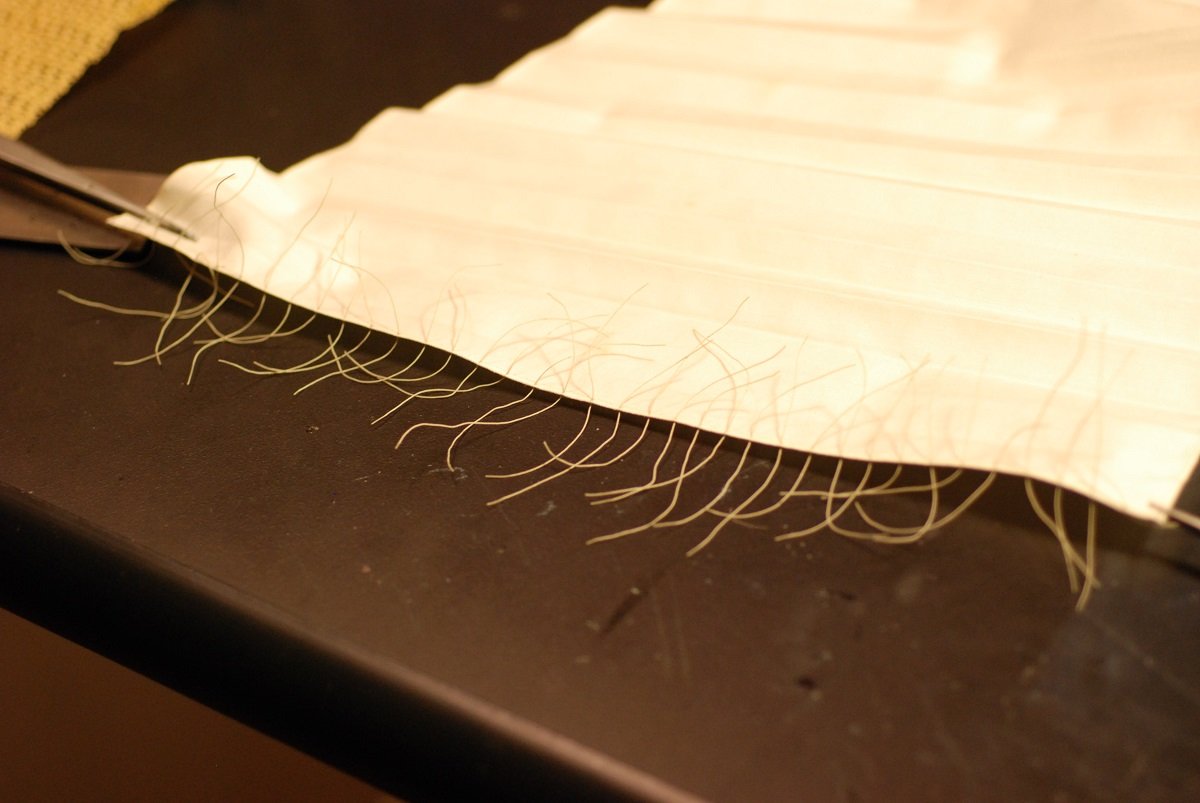
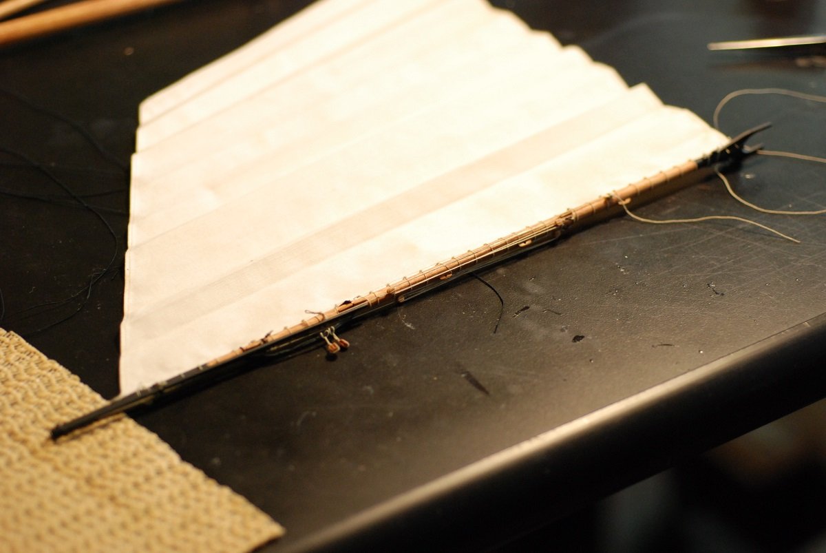
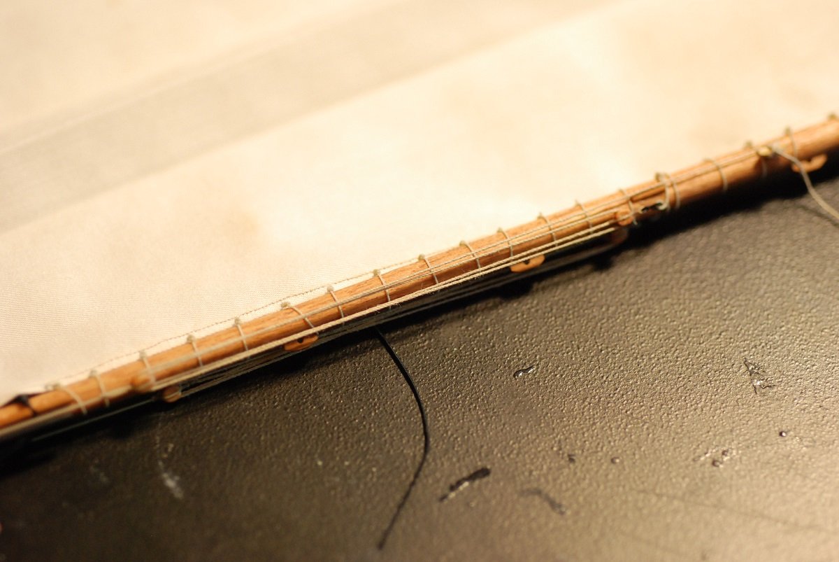
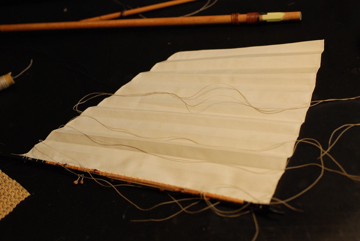
This picture shows installation of the sheets for the fore topsail yards. These lines for the upper yard run to the blocks at the mastcap of the mainmast, above the radar dome, then down to the deck. The sheets for the lower yard arise from the mainmast shrouds, running to blocks on the lower yard, then back to a pennant that is also attached to the mainmast shrouds. Then down to the deck. This pennant is about ½” in length. It took a lot of wraps of fly tying line to make it. Here is one of the rigs for securing the boom when at anchor or tied up at the dock. It ties off at a solitary pin on the deck rail. Here I am cleaning up the lazy jacks. It was difficult to work on one without over-tightening it and making the others suddenly look slack. Cleaned up pretty well, though. The mainsheet is of course quite long since the sheet runs through an extensive series of blocks, including a triple block between the (missing) ship’s wheel. The navigation lights are located on boards that are secured to the shrouds. The boards were manufactured from thin sheets of pearwood. Painting the lantern was a very delicate matter! Starting to work on the flags. The flag on Pride 2 is a 15-star flag, which as I recall indicates the number of states at the time of the War of 1812 or thereabouts. The flag was drawn using Paint, originally in a rectilinear manner. Then the skew function was used to skew the flag as you see it here. It helps to create a more naturally drooped final product. (Credit for the flag making techniques shown here belongs to Dan Pariser.) The Maryland flag was also drawn using Paint, and skewed in the same way. This one is printed onto fine cotton cloth, and before cutting it free, the edges were treated with an anti-fraying treatment. This was a first try for the pennant, printed on paper or silkspan. However, it didn’t handle crinkling well, as extensive cracking developed that you can faintly see here. A small amount of extra fabric was left on one short edge to accommodate the flag halyard. For each flag and pennant, the image was printed onto each side of the cloth, requiring mirror images of each flag and pennant. Pieces of fabric were taped over a paper onto which the flag had been printed, then run through the printer for the first side. Then each piece of fabric was flipped over and carefully taped to overlie its mirror image, and run through the printer again. Multiple attempts were done and the best was selected. The flag halyard cleats were very small. This image shows how much reduction of one of my stock cleats had to be done to achieve a scale size. These were then lashed to their respective shrouds with fly tying line. Ready for my closeup, Mr. DeMille... A yellow clamp at the level of the desktop secures the two halyards for the flag and the pennant at the mastheads. The Maryland flag did not droop quite as much as I would like. But I got a better result with the US flag. Each of these was crinkled by wetting with a spray of water, then crinkling it up and allowing it to dry. The lowest corner of the US flag was put under some tension to help it droop. This flag is rigged essentially on the boom topping lift. The finished model, with flags in place. A journey of more than 20 years is now at an end. I didn’t realize that there is a nice little history behind me of my other ship models! This one is by far the most complex, and the most satisfying. I moved it into the corner while awaiting the arrival of the display case kit. On the wall behind it is a model of Cuilaun, built by Rob Eddy of Camden, Maine. On the other wall is an antique map of the island of Martinique. My shop looks so clean at this time! I have mentioned it before, but my main workbench is actually a motorized sit-stand desk that has been essential. After a lengthy delay, the display case was ready. My neighbor and I VERY carefully put it in place while my wife took pictures. The glass case is actually a little too large for the bookshelves it is on, so I cut a piece of plywood for the case to rest on. My wife spontaneously said that it needs to be more prominently displayed than in the corner of my shop, which I was very pleased to hear! So initially it went onto the sofa table. But it seemed sort of vulnerable there. So instead, we cleared off this piece of furniture that was bought to support an antique mirror that came from France. And now both sides of the model are on clear display!


- 60 replies
-
- 8
-
-
- pride of baltimore ii
- Model Shipways
- (and 1 more)
-
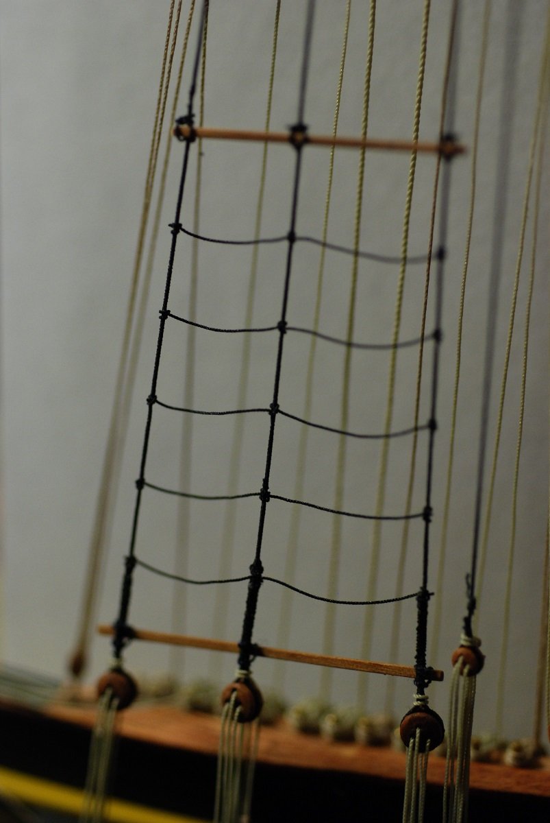
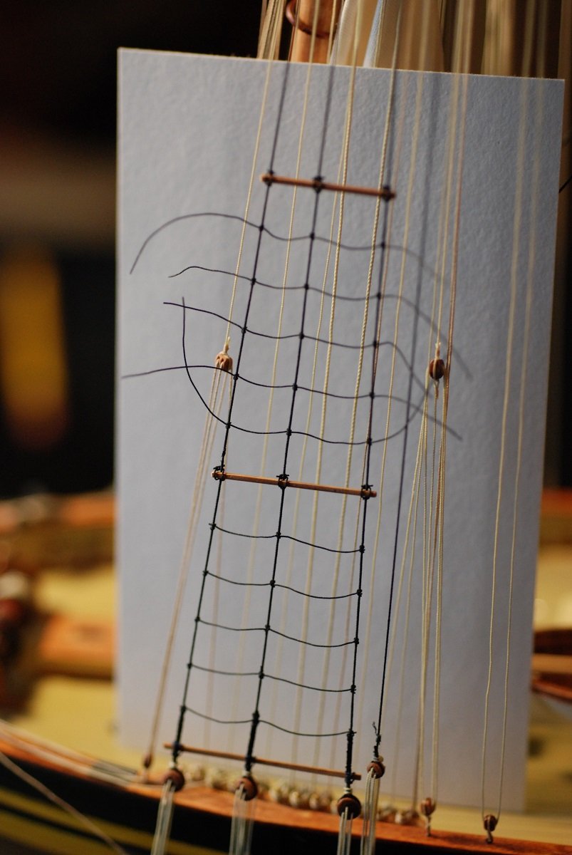
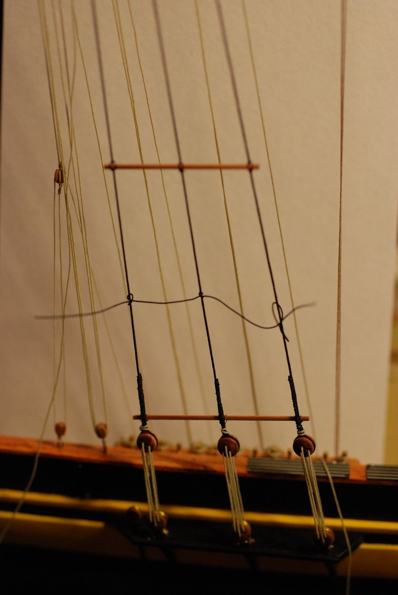
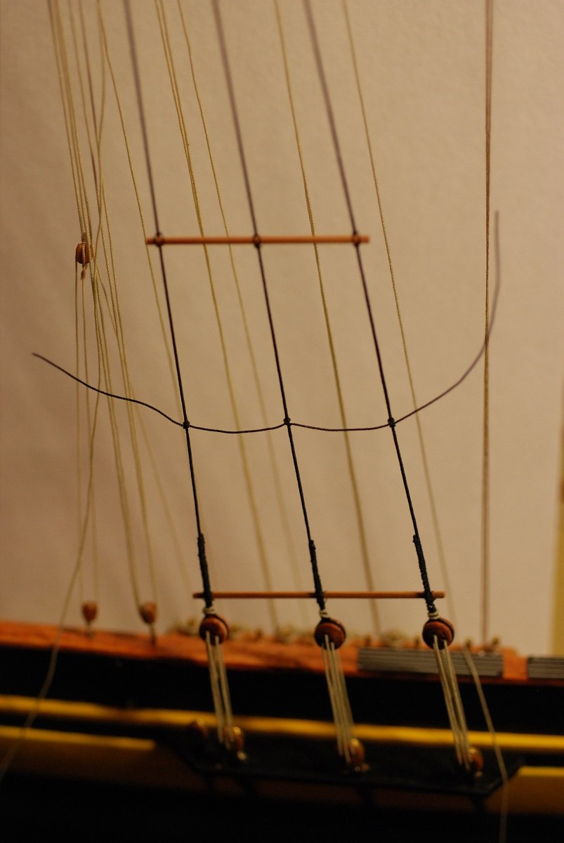
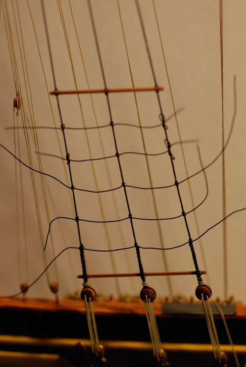
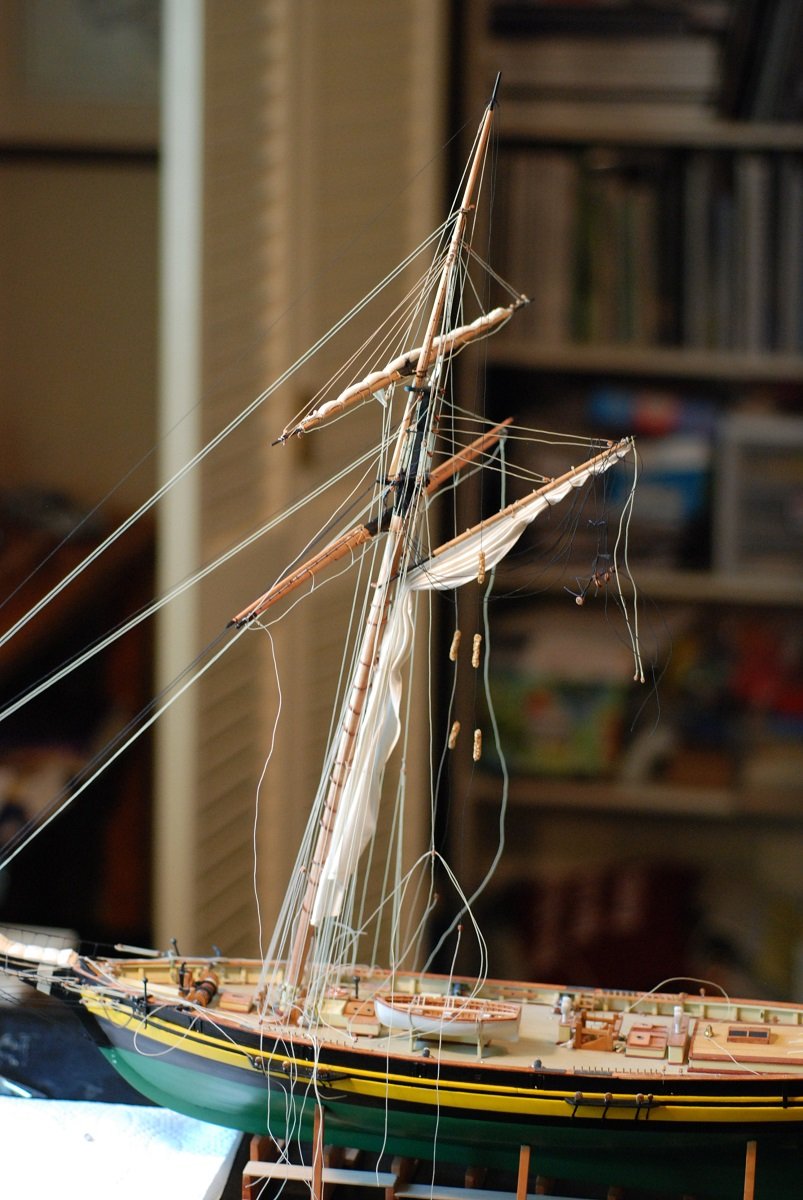
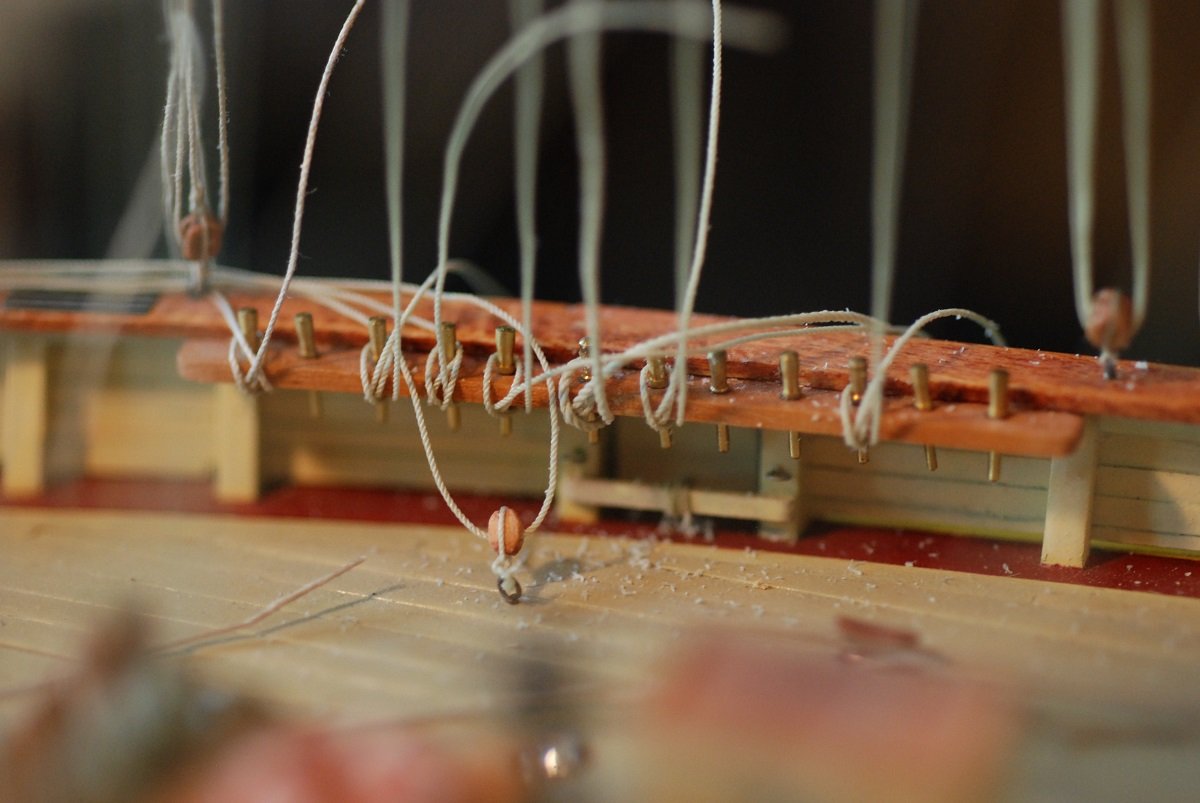
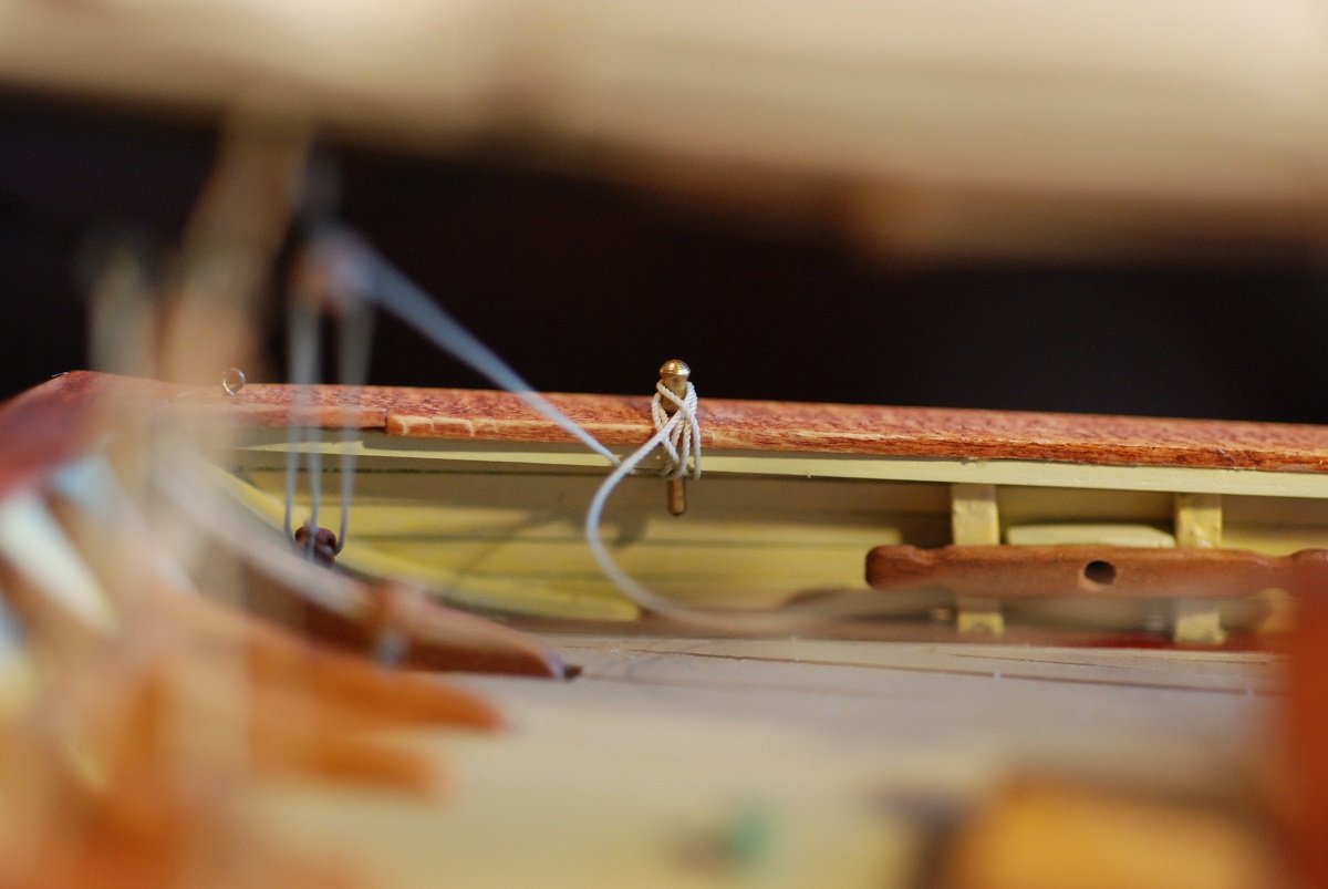
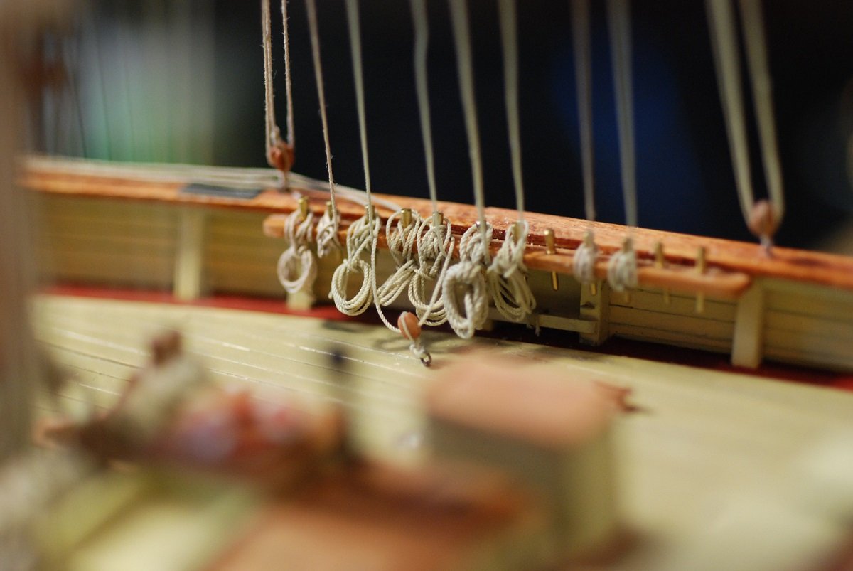
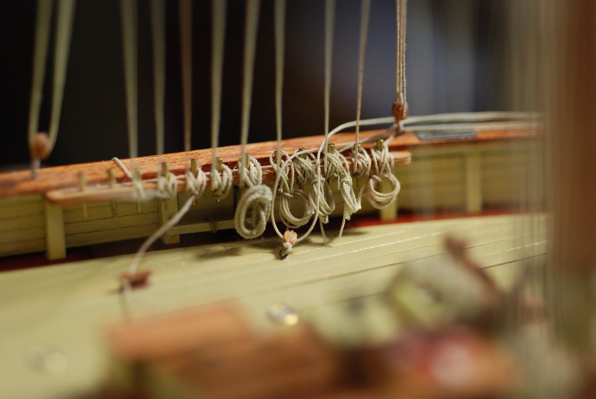
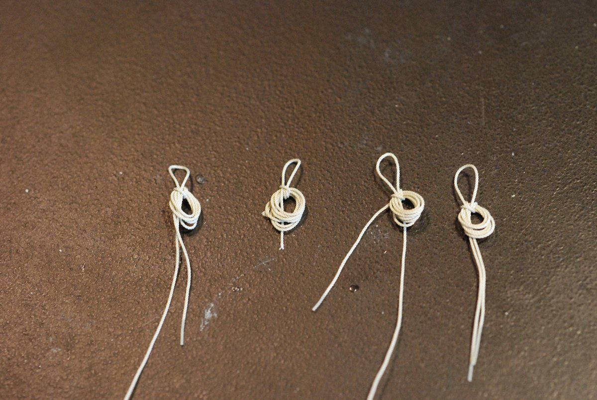
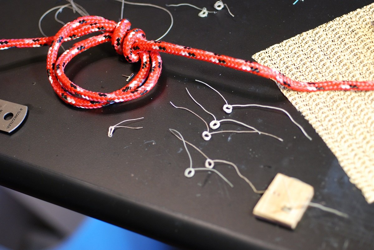
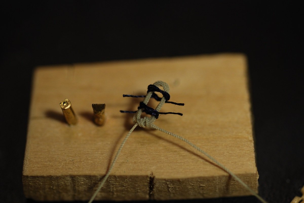
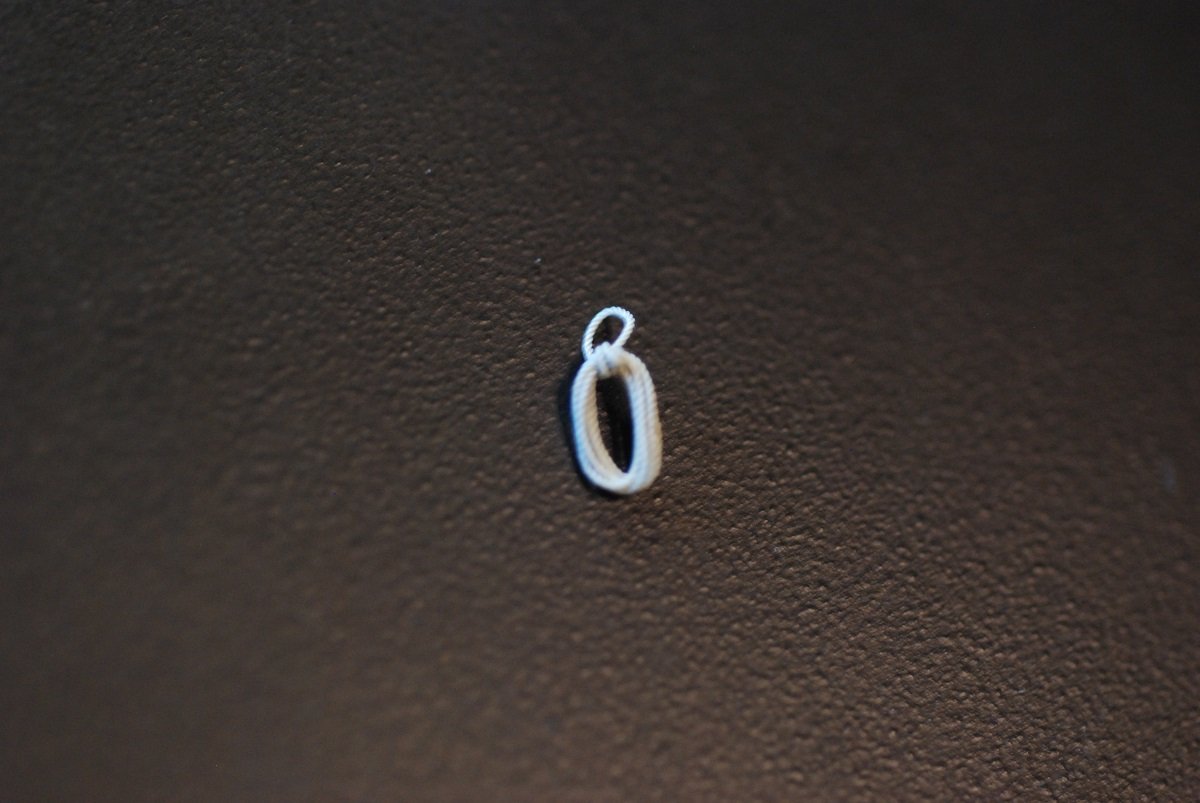
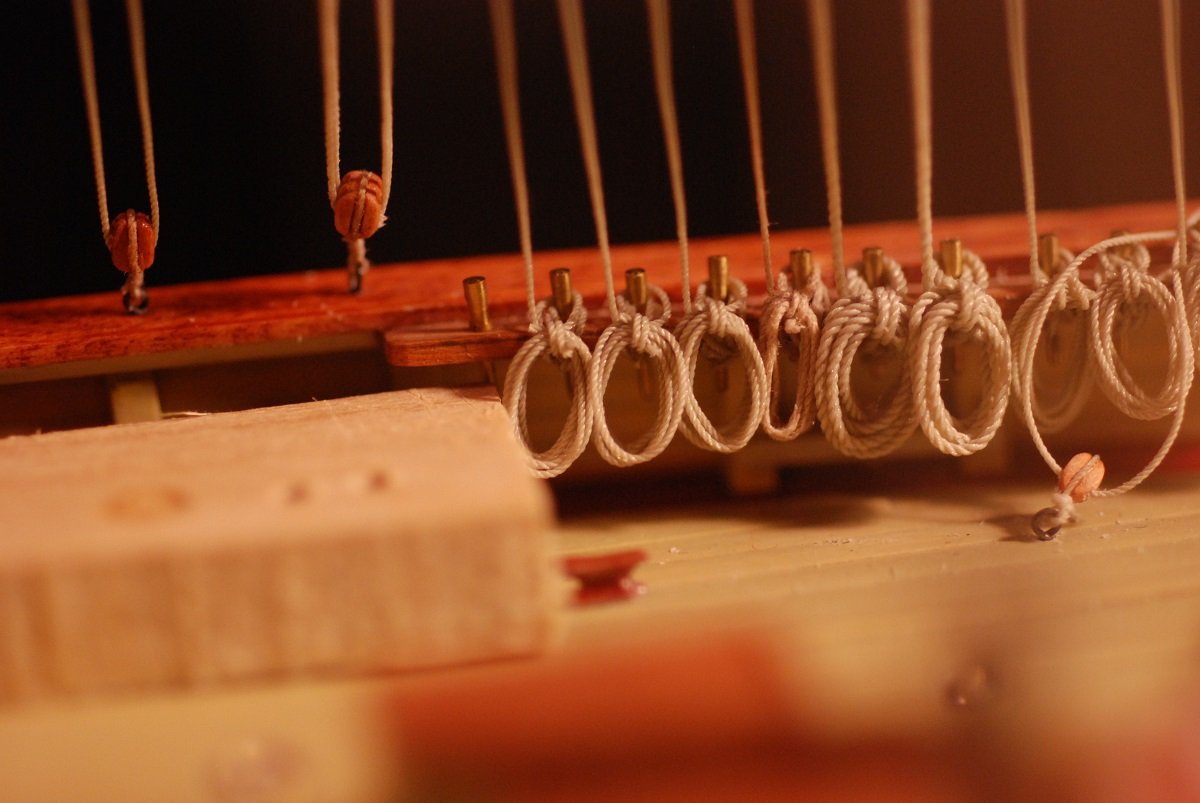
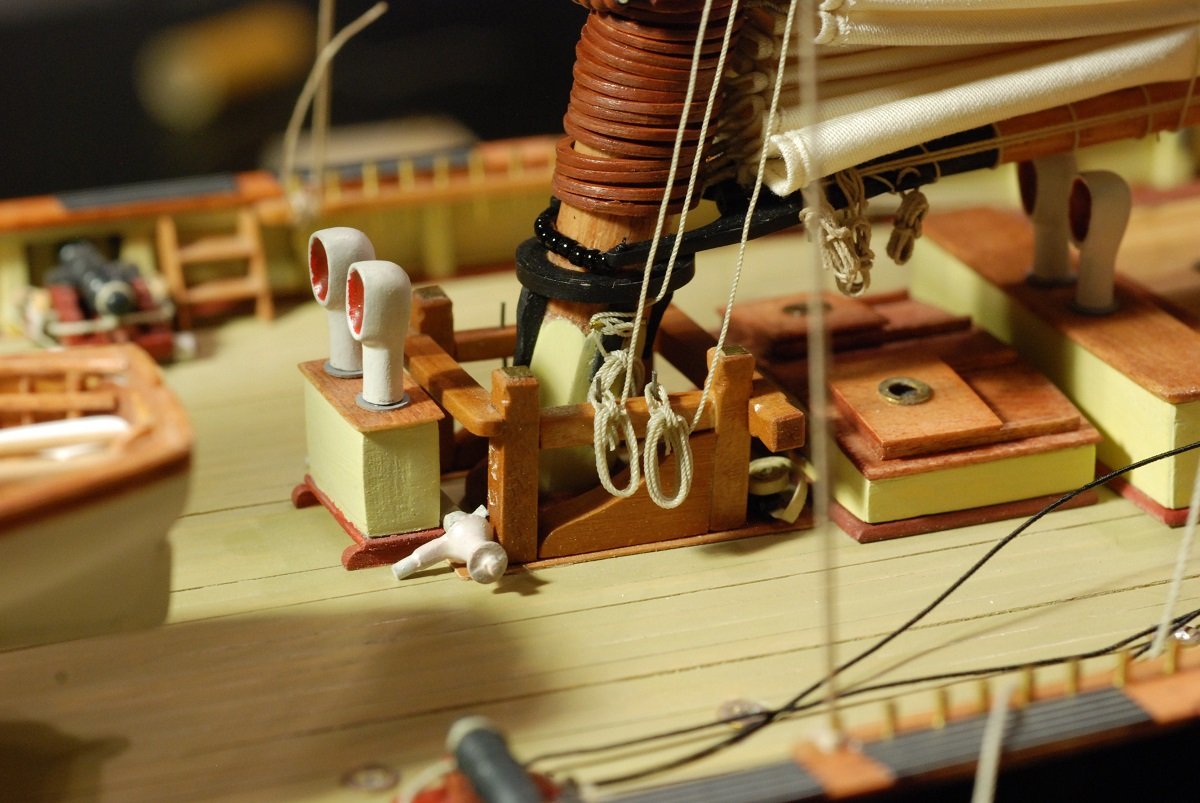
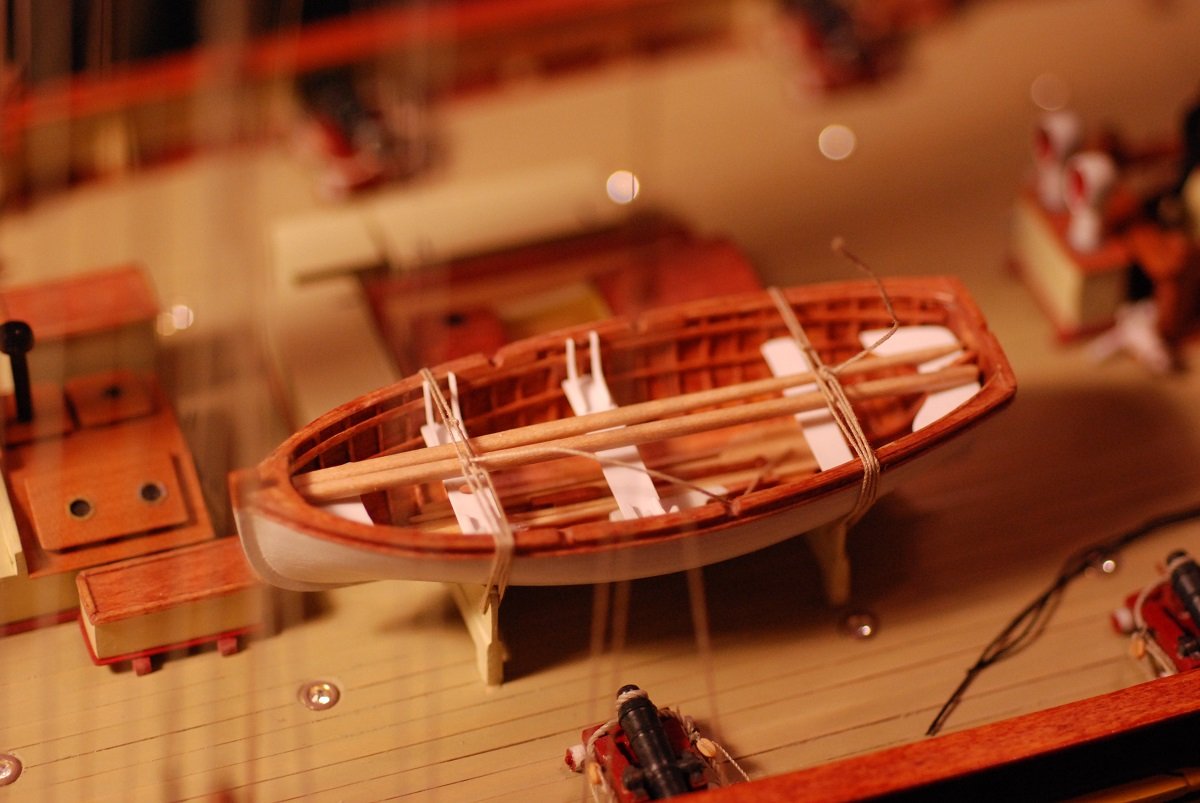
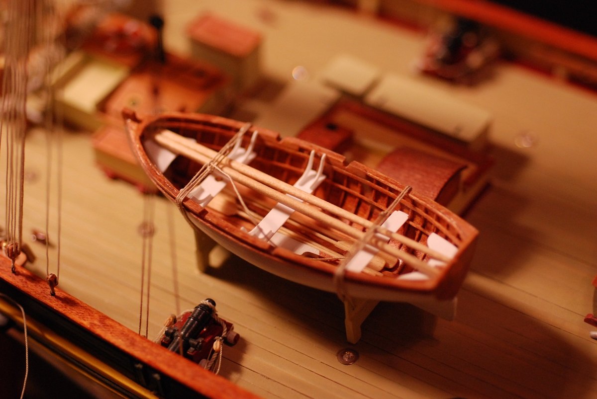
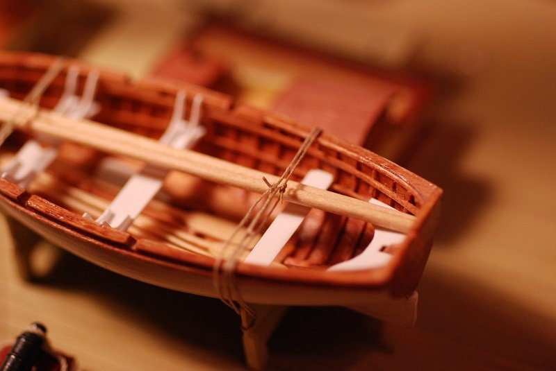
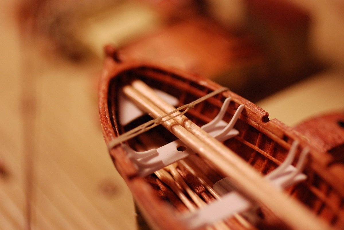
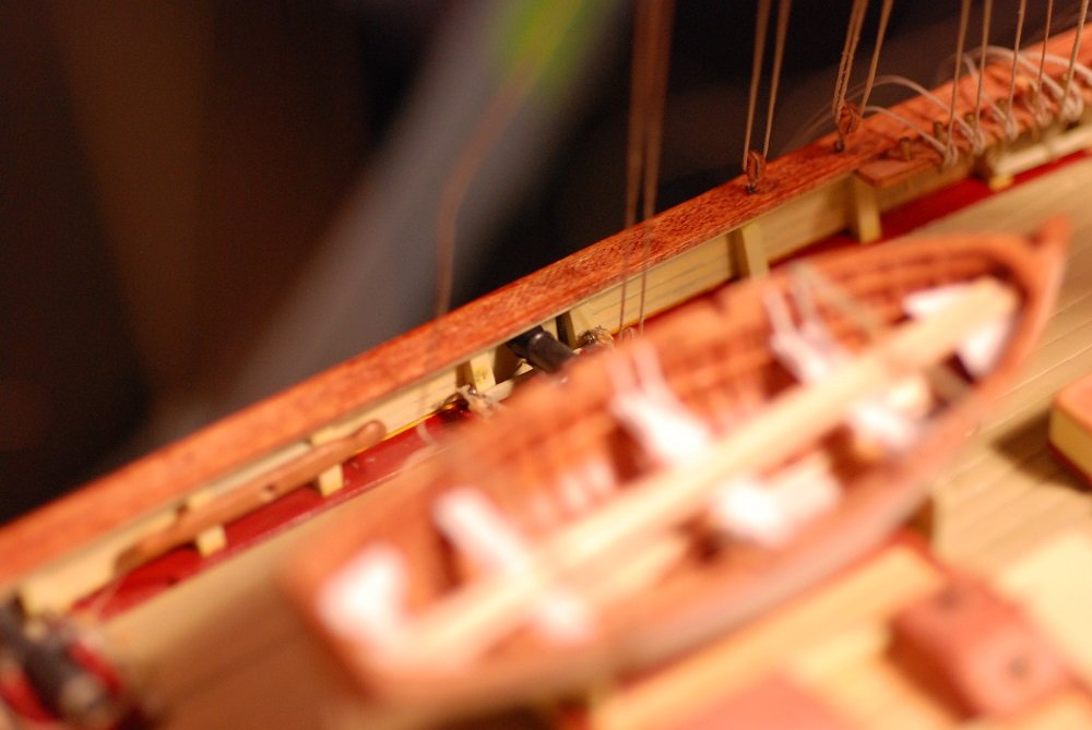
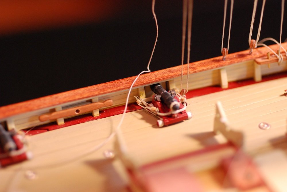
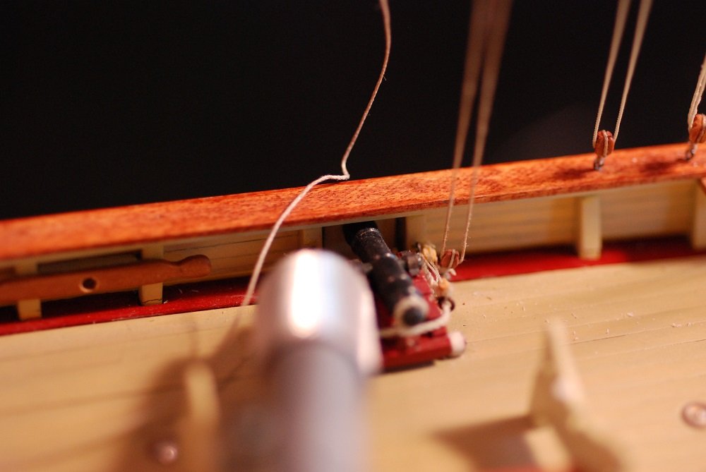
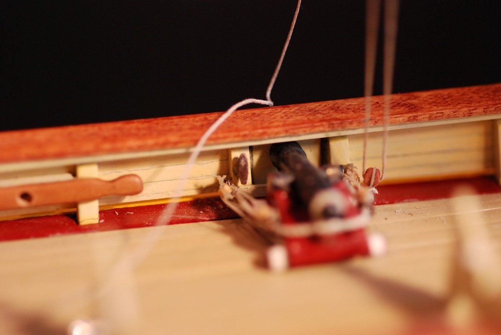
It’s time to address the issue of rope coils at the various pin rails throughout the ship. After rigging the foremast and foresail lines, I had a jumble of coils that were behaving badly, as shown above at the starboard fore pinrail. What a mess. This is the port side fore pinrail. I wasn’t happy with the technique I was using to this point, as I was getting very inconsistent results. These were some trial coils. Of course, as I am sure is common among us, the line is tied off to the pin rail and then the extra is cut, then a rope coil is created off the boat and applied over the cut line. Hey, if you don’t tell anyone my secret, I won’t tell on yours… I spent time playing with a piece of full scale line to try to come to a stable way of coiling line and adding a loop that would go over the pin, while leaving a coil that would realistically hang down. I also solicited a lot of helpful feedback from others on MSW, although when I try to go find my post, I can’t seem to find it. I gravitated toward this technique, with two metal posts in a block of wood around which line was coiled up. Then smaller thread was used to force it out of its round shape. Then one end of the line was passed through the wraps to give the loop that would go over the pin. A lot of effort at this point centered around what glue to use to get the line to hold these shapes. Thin CA certainly worked but was too difficult to control. These are what my coils looked like prior to forcing them out of their round shape. This is more like it. I settled on an Elmer’s product called Elmer’s Pro Bond Advanced. White glue didn’t seem to work well on Morope, which was probably because of its synthetic fibers. A finalized loop. I tried to avoid the use of CA due to the varying opinions about its stability over the long term. However, it was the best option for securing the coil of line to its pin. I could direct a very small droplet to the pinrail and place the loop over the pin, with just enough time to adjust the position of the coil before it firmed up. A couple of loops at the pinrail at the foot of the mainmast. Finally, a reproducible technique that I will hopefully be able to remember when it comes time to rig my next model! These logs are invaluable for that. And just in the event of another website crash (sorry, shouldn’t have mentioned it!), I keep these logs in Word format too. A brief interlude to acknowledge the reinstallation of the ship’s boat, Chasseur: Chasseur was removed earlier because I had to reinstall a cleat located on a bulwark stanchion immediately next to the cannon visible in the picture above. I was able to duplicate the line scheme that secured the boat to its cradle. Nostalgic moment: the first part of this project I did when I resumed building the Pride 2 after raising our first child to the age of 10 was to build the ship’s boat! I am very satisfied with how it turned out. Next topic: Shrouds and ratlines! Here I am using fly-tying thread to seize the shrouds around the deadeyes. I learned later, and maybe I mentioned already, that the technique I was using to tie these seizings is called a “country whipping”, where overhand knots are tied on the front and then the back of the shroud, over and over again to achieve the long seizing depicted above. Country whipping sounds like something I used to endure as a kid… The forward deadeyes on the port side are now seized, and the lanyards have been reeved through the deadeyes. Next the sheer pole is installed. Footropes applied to the port side foremast shrouds. A white card behind the shrouds made the line so much more visible. Now the after shrouds. The sheer poles were placed first, in order to accurately space out the footropes. What follows is a series of images showing my sequence of events for tying a footrope. Started with the center shroud, using a clove hitch for all the knots. It’s quickly evident that the footrope to the right of the center shroud is going to try to bend upward against gravity, while to the left of the shroud, the line hangs more naturally. There was no way to counteract this upward slope of the footrope to the right of the shroud except to fix it in a downward angle with a tiny amount of CA. That’s better. Fortunately that was the only part of the footrope where the angle of the line had to be corrected. CA was also used to secure the clove hitches at the ends of the footropes, so that the excess could be cut neatly without risk of the hitch unraveling. Pretty neat. Once again, white cardstock was essential to be able to visualize things well. Getting pretty close to the end! Gonna stop here for today, I think. Maybe I will finish up these posts tomorrow...


- 60 replies
-
- 3
-
-
- pride of baltimore ii
- Model Shipways
- (and 1 more)
-
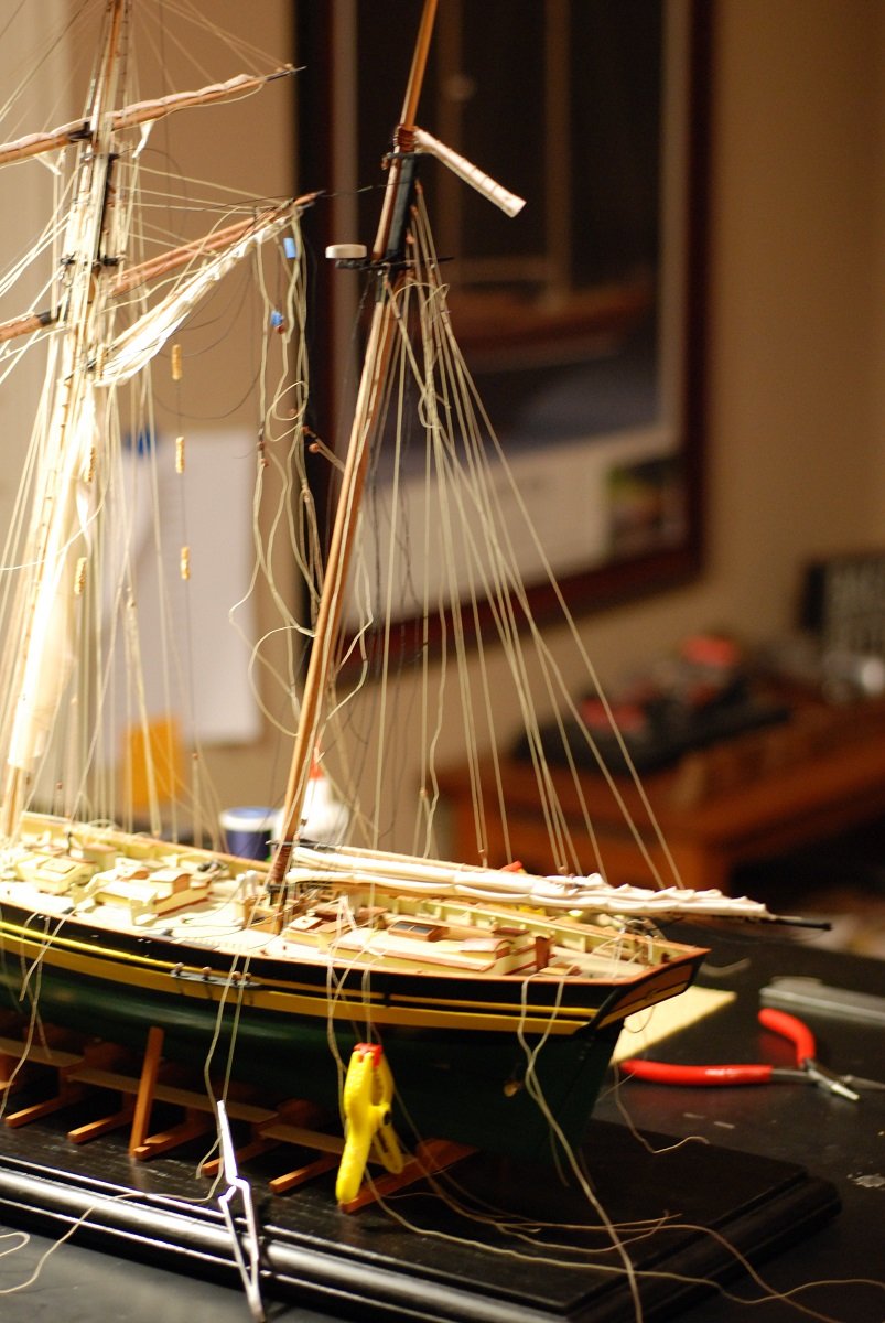
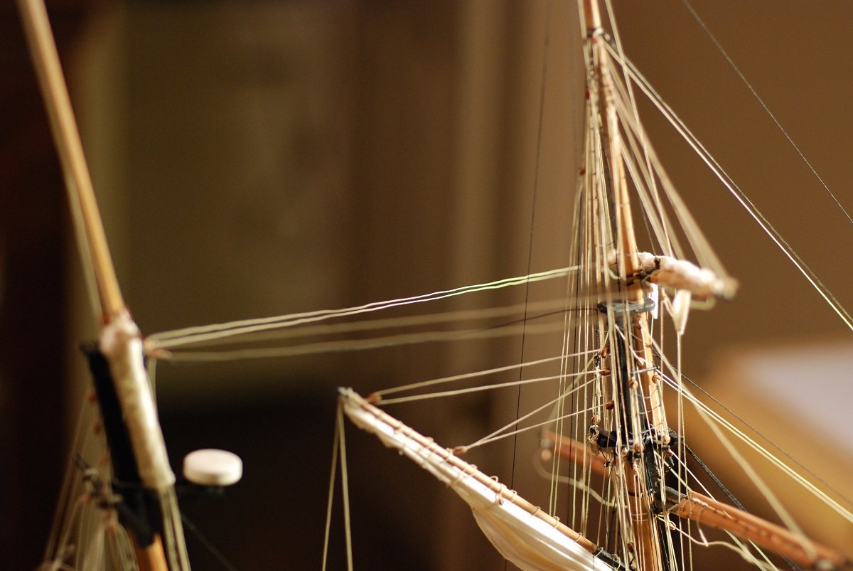
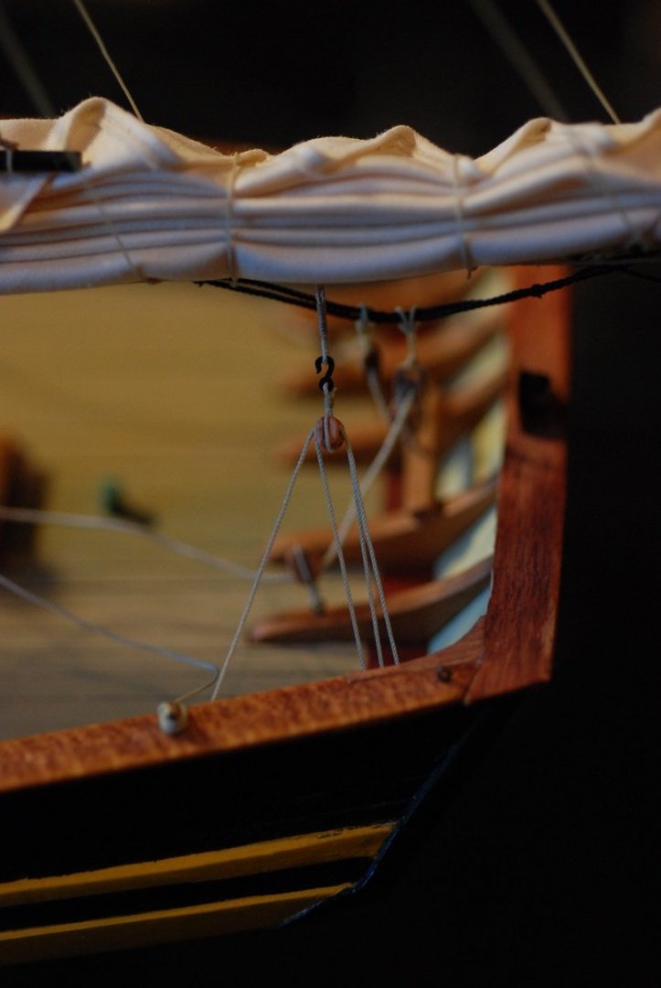
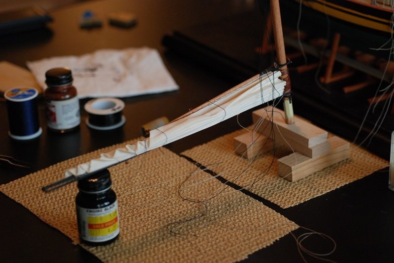
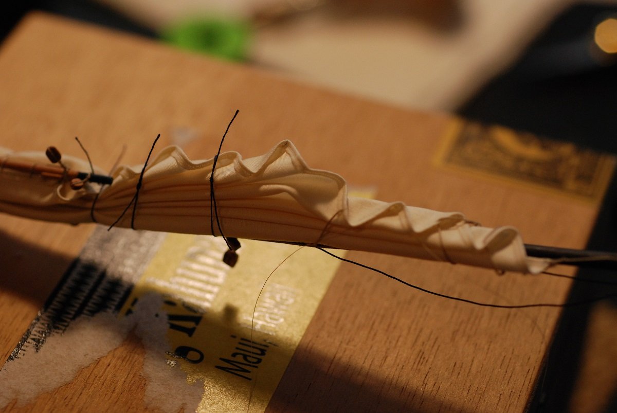
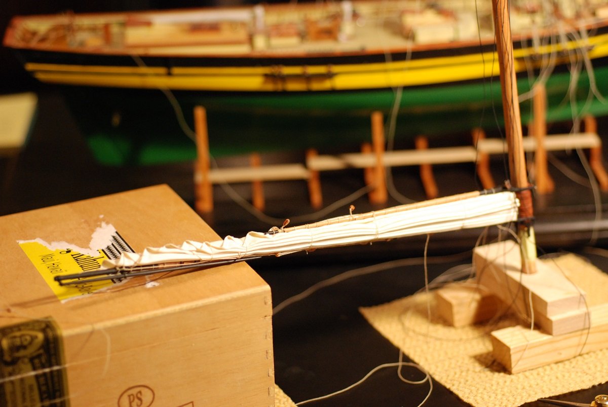
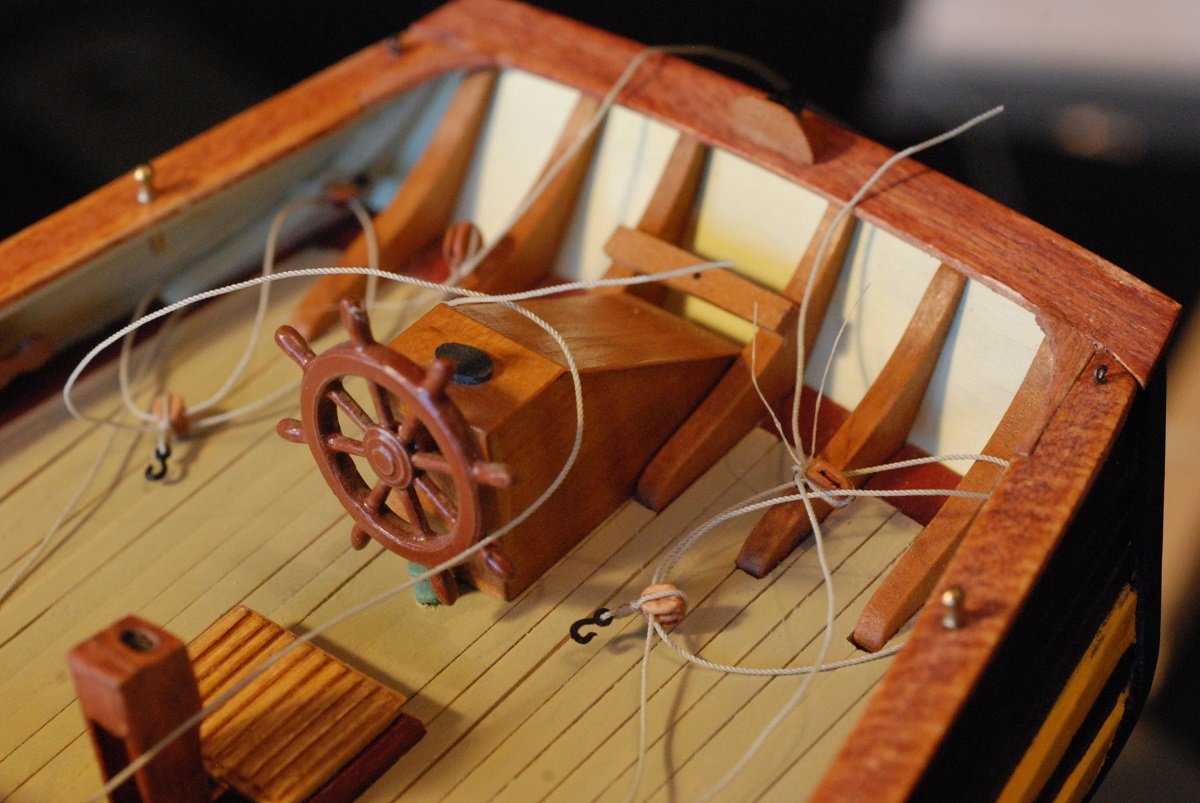
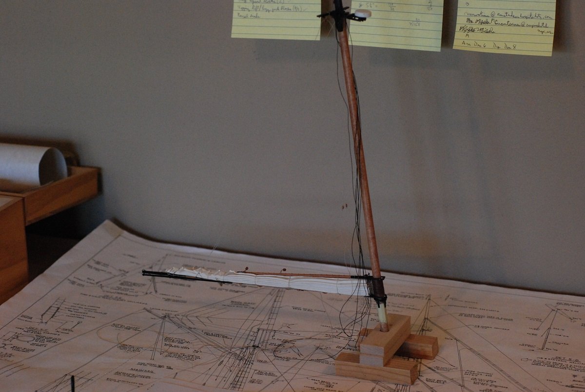
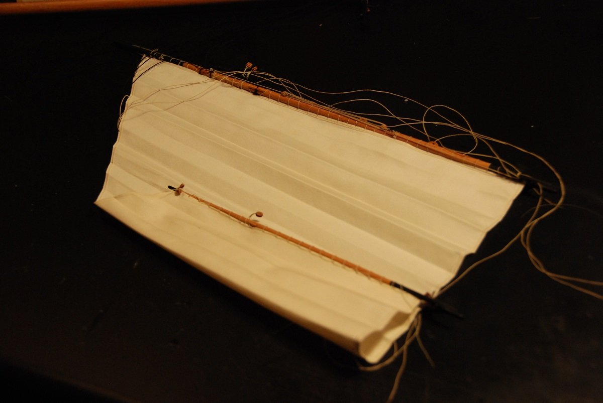
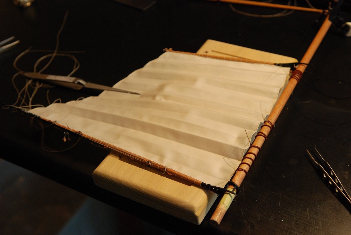
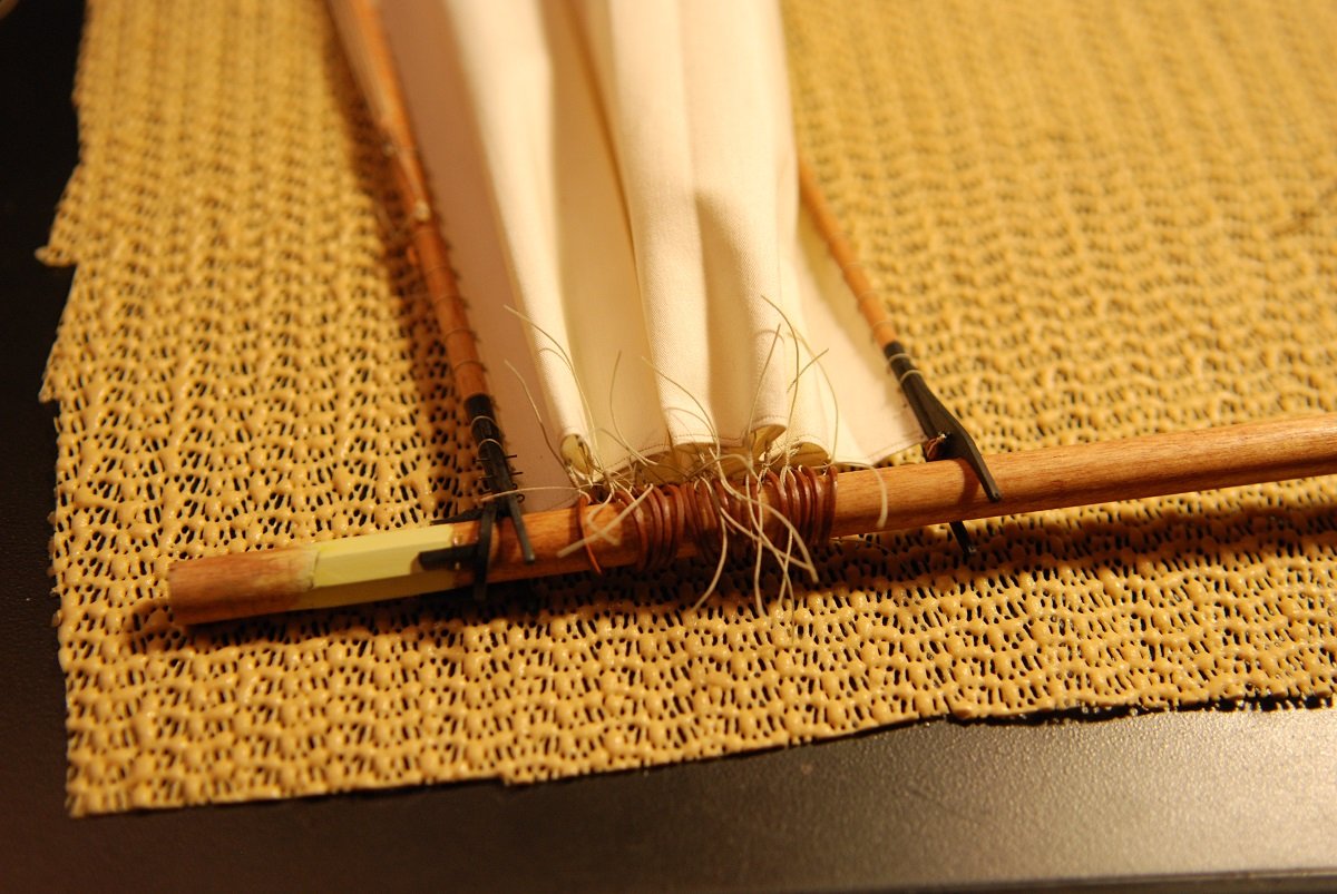
At the prompting of Meddo, I am going to try to finish off posting my pictures from the Pride 2 build. And high time too, as I am now making significant headway on my next ship model, so I will need to start that post once I finish this one! So, I created a jig that would support the mainmast while I worked on the main boom and gaff, and its associated sail. The mainsail had been ironed to give it a flaked appearance. Black thread is being used to bundle everything up temporarily. It was a bit of a trick to keep the gaff from falling to one side or the other. Next problem: the relative stiffness of the sail fabric caused the leech of the sail to bunch up and stick up. Putting tension on the outhaul lines helped matters, but still needed more work before the temporary black thread could be removed. In the end, I had to take fine fly tying thread and essentially sew down the folded leech to the sail material underneath it and give it a neat appearance. In preparation for installation of the mainmast and mainsail, these lines had to be installed. These are control lines for the boom that are used when the ship is docked. They are rigged to double blocks that have an associated hook, and the hook attaches to the boom. Now the mainsail has been tacked down, and the mast is ready for placement. The main mast in place, awaiting adjustment of its lines. A really exciting moment, as both masts are in place! I did not glue either mast in place, figuring that it was not necessary. They aren't going anywhere... Starting to rig the mainsheet through its blocks. Hey, wait a minute...isn't something missing that was there before?? The view from the starboard quarter. What followed next was an extensive process of rigging the halyards for the gaff, putting them under some tension, and then tightening the mainsheet and the boom control lines. This took a lot of trial and error to make sure that both of the halyards and the mainsheet were under tension…but not too much tension! Then each of the mainstays for the mainmast had to be secured at their rigging points adjacent to the foremast base. Here the mainstay rigging line is being coiled adjacent to its cleat, and is secured with dilute glue. I love working on the rigging! It is so very satisfying to see that jumble of lines begin to take order as everything is put in its proper place. My favorite part of building ship models. And this has been my most intricate model to date. Very close to being finished, so I think I will keep the momentum and work on the next post. That mainly means shrouds and ratlines, and putting rope coils in place. Hopefully that post will be here shortly! Plus this Coronavirus stay at home thing really has me in a productive mode.


- 60 replies
-
- 2
-
-
- pride of baltimore ii
- Model Shipways
- (and 1 more)
-
Meddo! Been thinking of you as we wait for the onslaught of patients in Dallas and Dayton. Work is slow because aside from the cases of viral pneumonia, everyone has been keeping away from the hospitals, as you probably know. The model is finished, I just haven't done a good job of continuing my retrospective posts. But you will inspire me to resume them...
- 60 replies
-
- 1
-
-
- pride of baltimore ii
- Model Shipways
- (and 1 more)
-
Sadly, no. I have too many other travel plans this fall, particularly during October. Have fun!
-
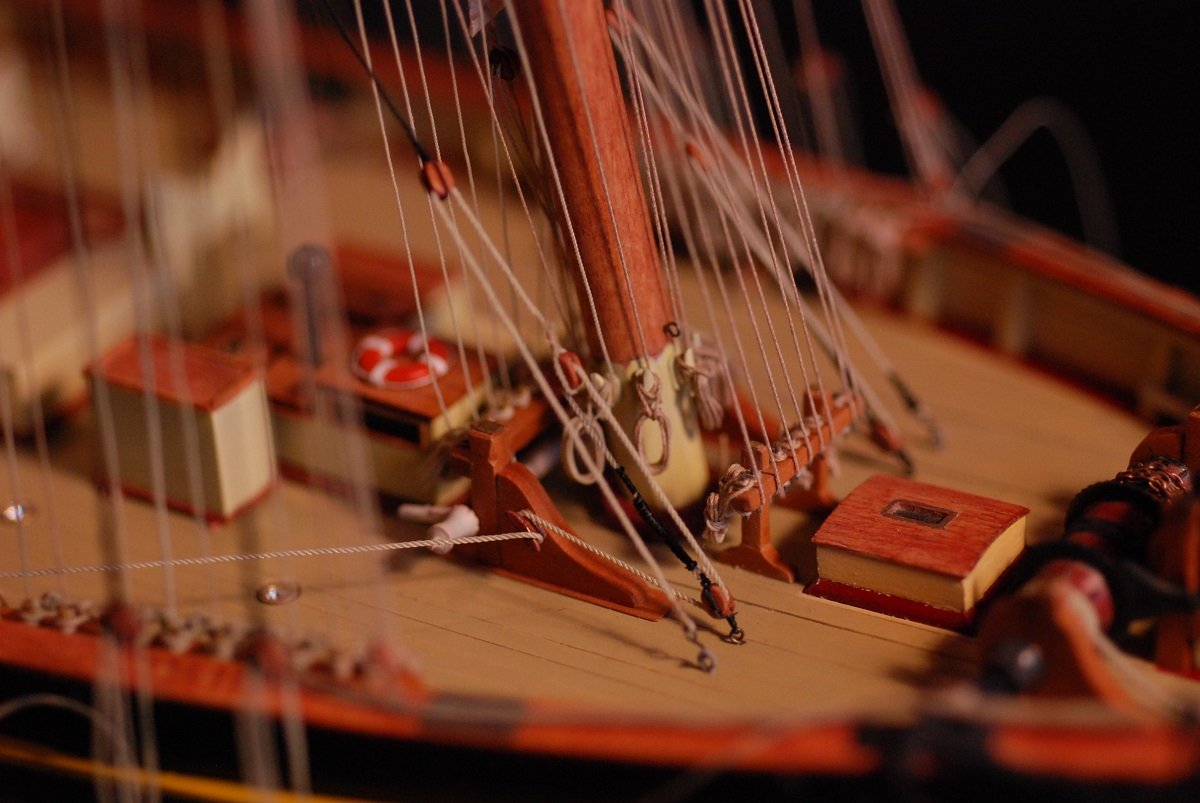
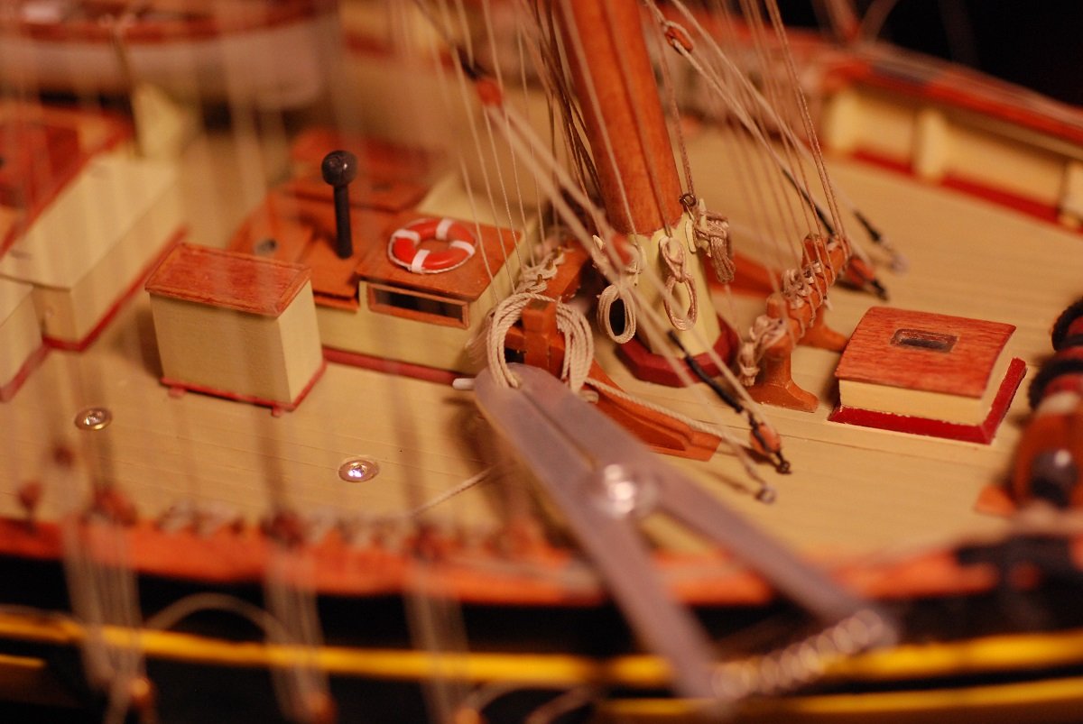
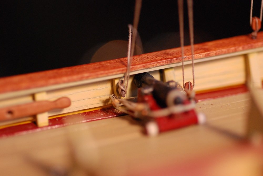
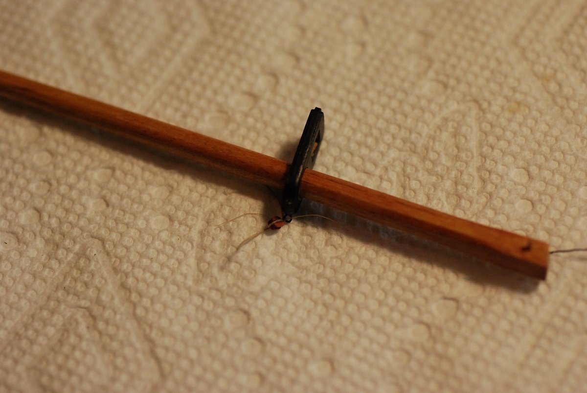
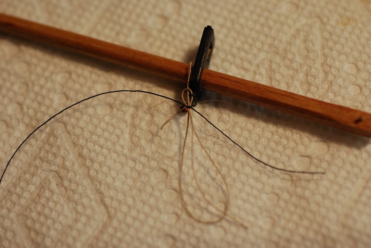
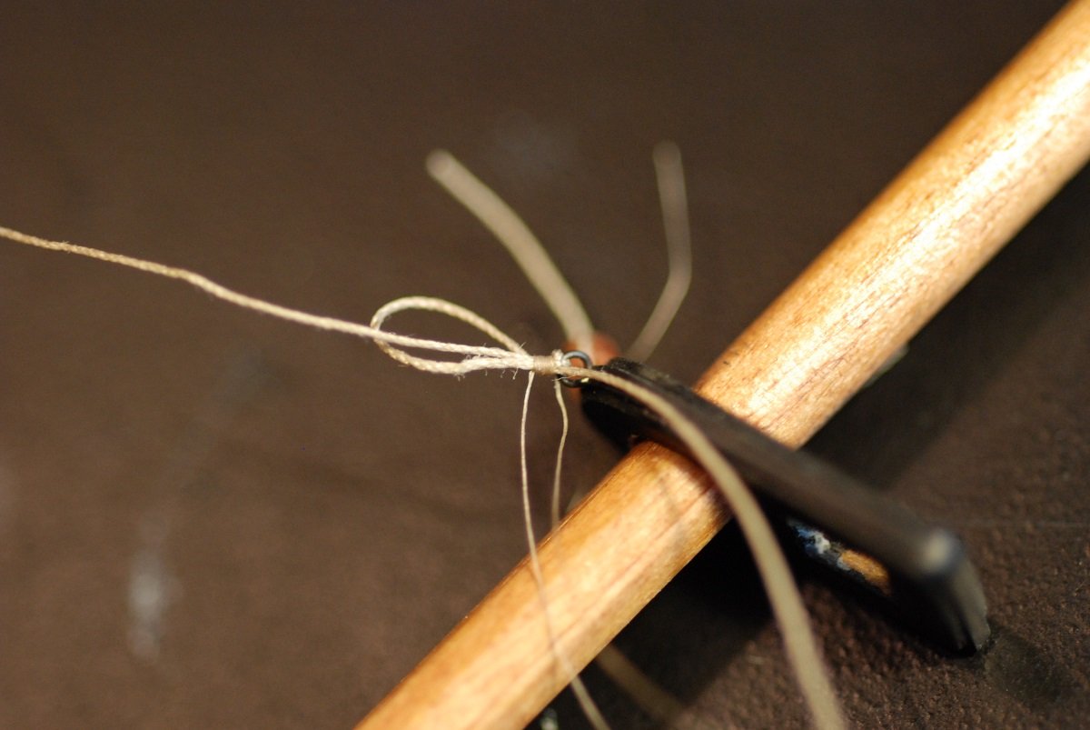
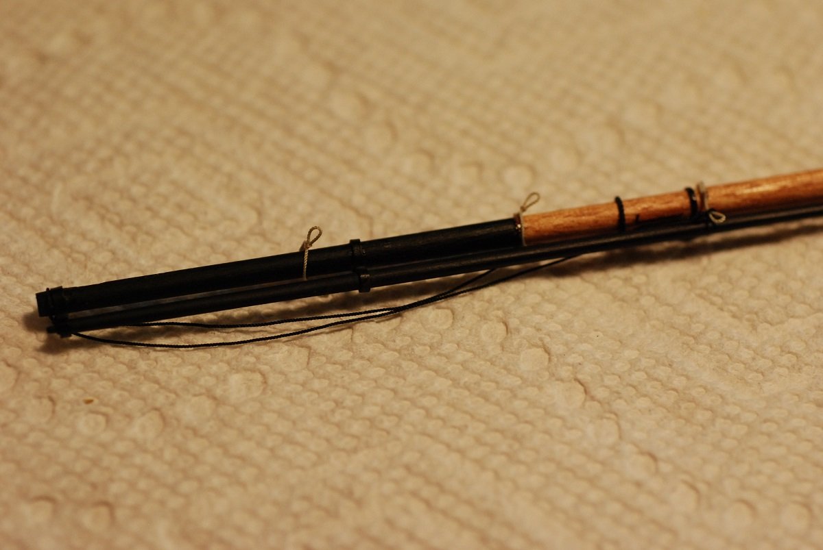
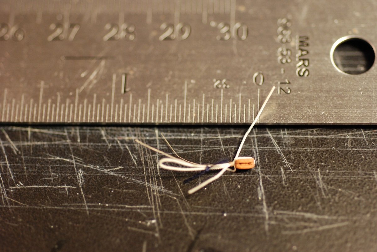
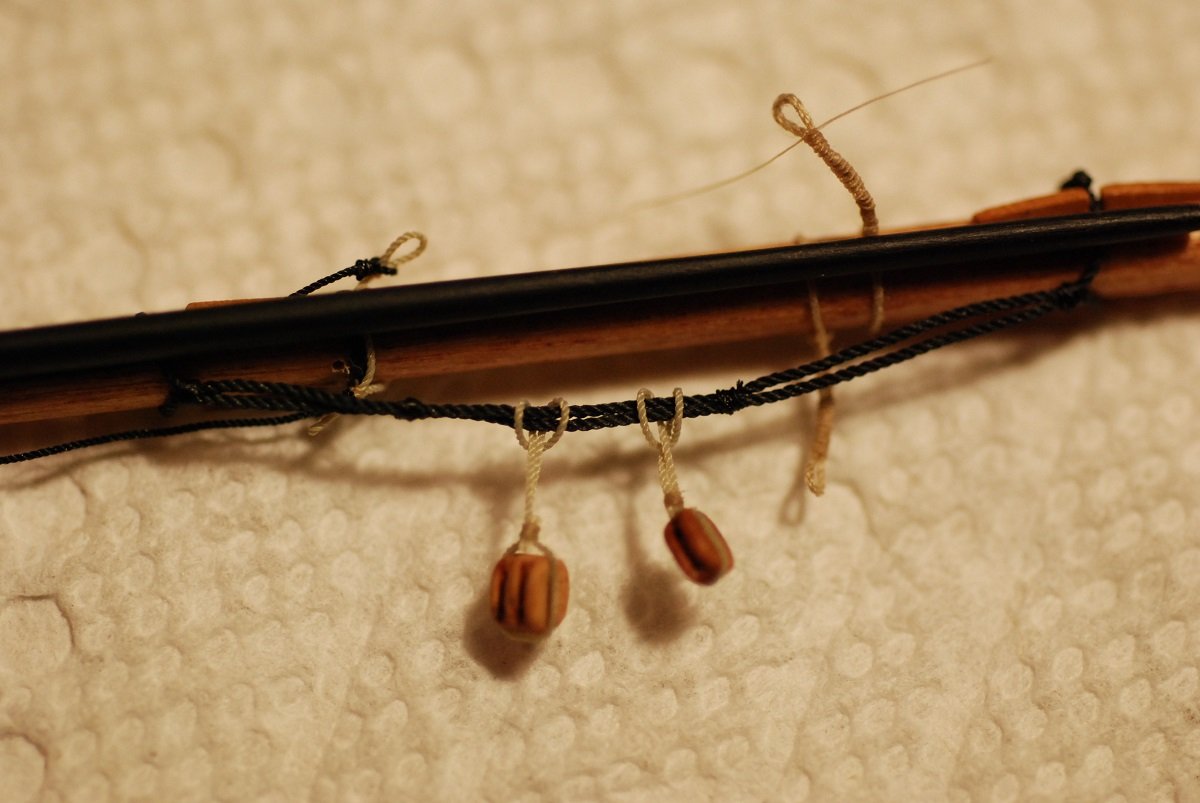
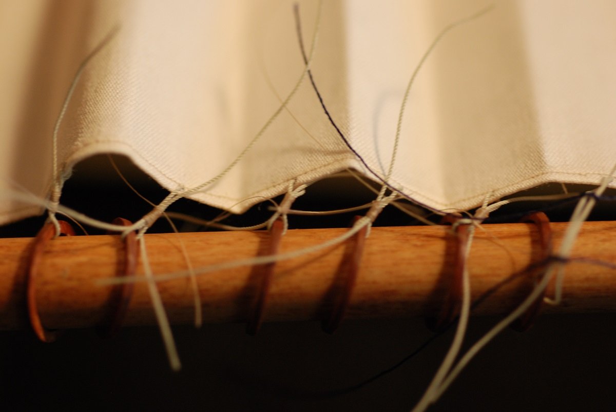
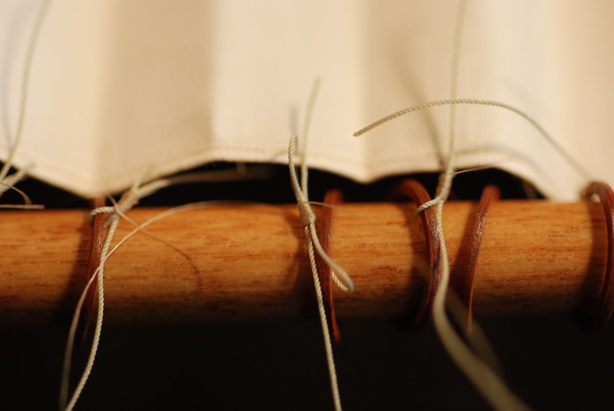
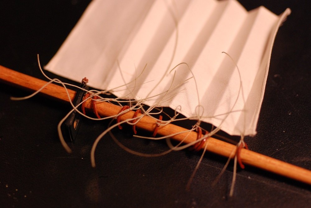
Before we get to the mainmast, got to deal with Chasseur, the ship’s boat. I created tie-downs for the boat that thread through holes in the cradle. I didn’t have any particular description of the tie-downs, so I just created what seemed to make sense. Uh oh, now I have a problem. There is a cleat along the port side rail where one of the backstays for the foremast ties off. With the ship’s boat in place, that cleat is very difficult to access. To make things worse, at some point the cleat broke off from the bulwark. Replacing it with the boat in place is impossible. Sigh. So those tie-downs were cut after I made a note of how I had made them, and the boat was removed. I had to create a hole to attach the new cleat. The old cleat had no firm physical attachment to the bulwark besides glue. So here I am drilling a new hole. I drilled a hole in the base of a cleat and glued a short segment of wire into the hole. This was used to create a more secure attachment point for the cleat. A small amount of paint was scraped off of the bulwark surrounding the hole, and the cleat was glued to the bulwark. The line is secured to the cleat in the proper configuration; later on a coil of line will be added over it. So now work begins on the main topmast. Blocks have to be attached to the mainmast cap, which are control blocks for the fore yard. This is the same technique used for attaching blocks in other parts of the rigging, with a double loop of Syren line that is then seized with fly tying line. Once everything is tightened, Flexament is applied to the seizing, and topcoat is applied to the block. I love being able to see what the seizing looks like up close using my microscope. I really need to get a camera attachment for the viewfinder, because getting this picture with my iPhone is actually very difficult to line up through the eyepiece. This seizing has not yet been treated with Flexament and topcoat. This is the topsail rigged to the main topmast. Since it will be modeled in a furled state, its overall shape doesn’t matter. This rectangular shape worked well for furling it into a nice tight bundle. The sail is being rigged to its mast hoops with line that will get all cleaned up once the seizings are secured with glue. For that step I was able to remove the sail from the mast and bundle it up, first with coarse black thread… …then more properly with tie-downs made with Morope. Very small reefing knots… Now it’s on to the main boom, which had previously been manufactured and cleats and jaws attached. Here I am attaching some footropes to the aft portion of the boom. Well, they aren’t actually footropes, but rather the attachment lines for the mainsheet blocks. This picture shows the relationship between these ropes and their respective cleats. These loops will serve as downhaul points for the reefing lines of the mainsail. Fly tying line was used to secure them to the boom. So here they are in place, giving some idea of where the reefing downhaul points are on the boom. This is one of the blocks for the mainsheet, which will get rigged to the black lines shown above. The mainsheet system consists of a single and a double block attached to the boom. The lines run from these blocks to additional blocks at deck level on either side of the ship’s wheel. Time to rig the mainsail to the boom. Ready to start securing the foot of the mainsail to the boom. Plus the same process for the head of the sail, attaching to the main gaff. And now, the luff is getting attached to its mast hoops. The usual technique, using a double loop of line that is then seized in the middle. Only these seizings are significantly longer than the ones for attaching a block to the rigging. A bit messy, but these lines will get trimmed off and things will look neater. Under the sail and its spars, I have some anti-skid material that is used under rugs. It’s great for keeping things from sliding around on the desktop. Will continue on the main mast in the next post.
- 60 replies
-
- 6
-
-
- pride of baltimore ii
- Model Shipways
- (and 1 more)
-
My most recently completed model took over 20 years to build. Within it lie many memories, both good and bad. Mostly good, fortunately. I came to learn that the model is like a surrogate of my marriage: something that took much attention to detail to build; something to be very proud of; something that is very fragile and can easily be destroyed. I am hopeful that your model will remain with us so it can continue to serve as a testament to everything you have been through.
-
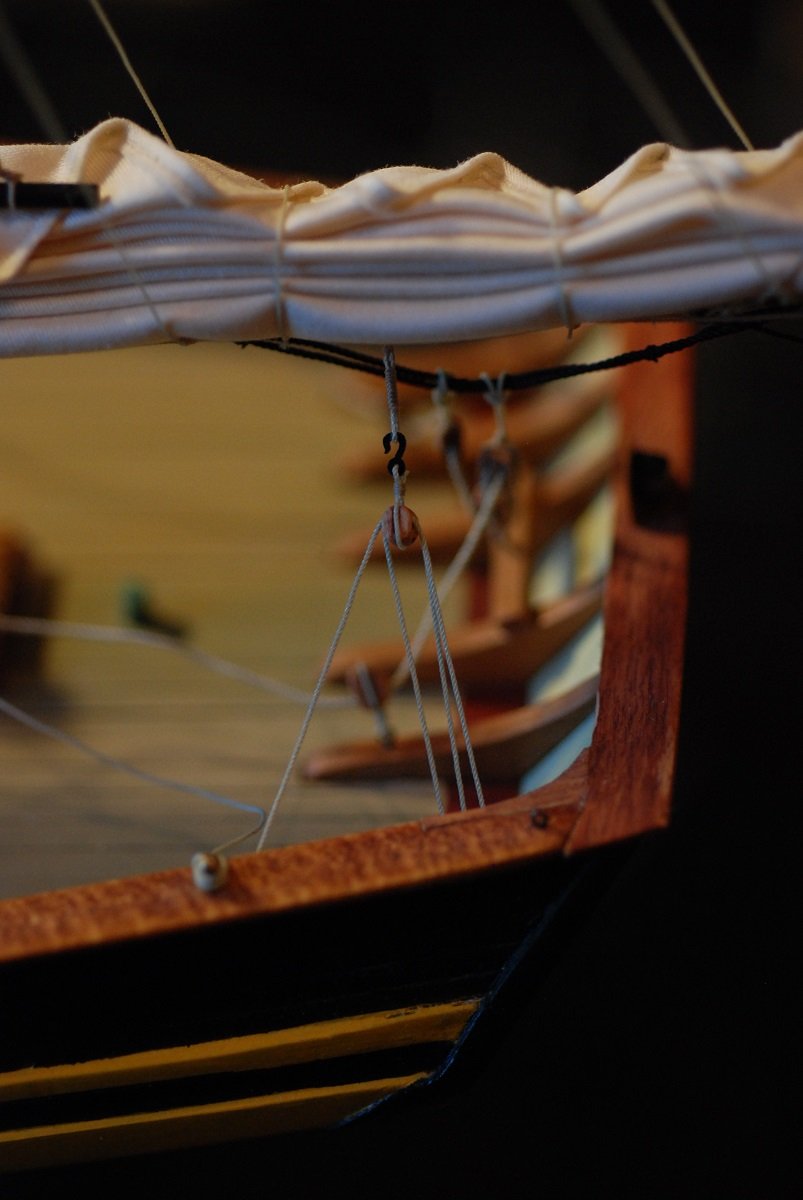
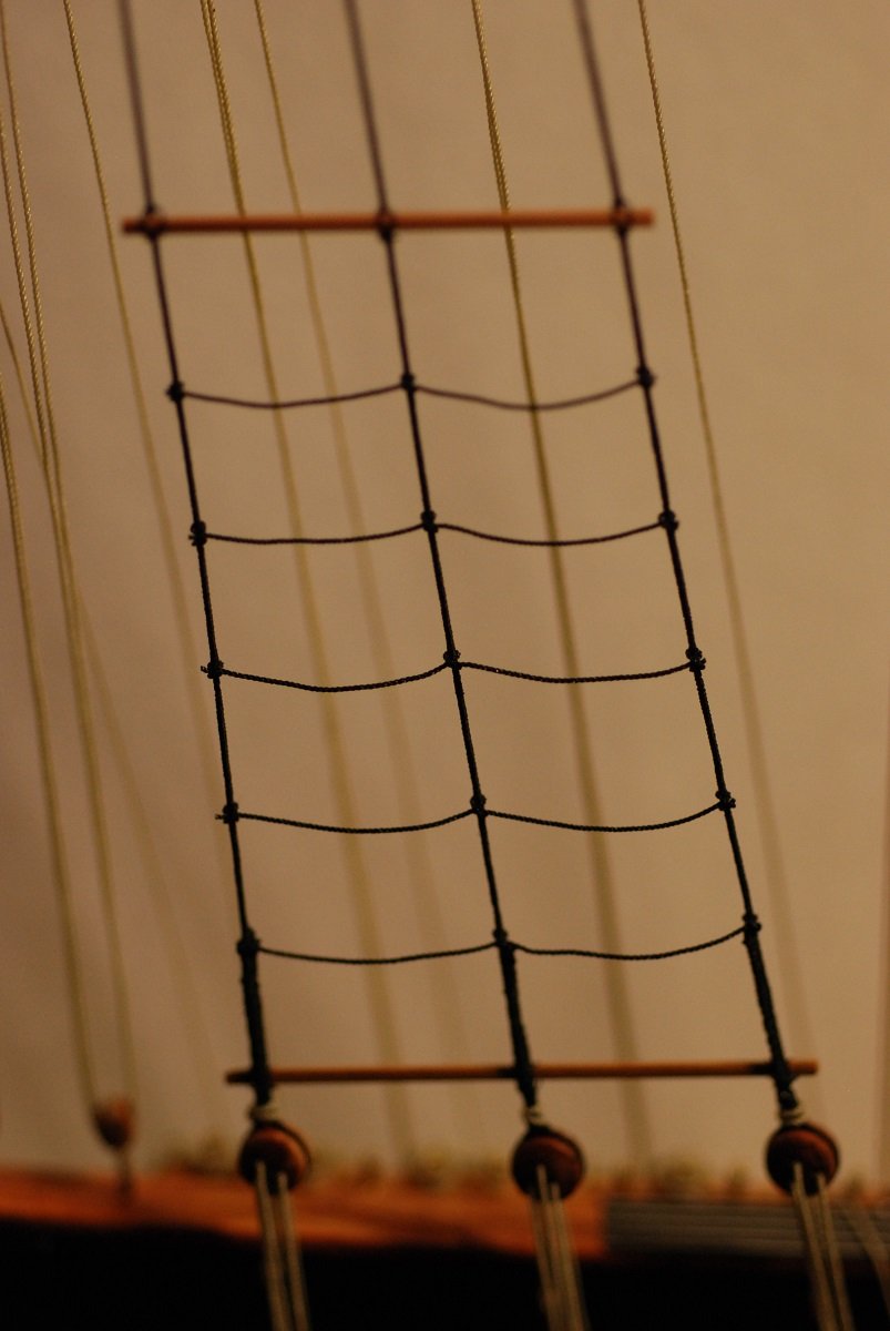
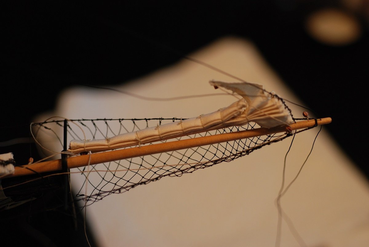
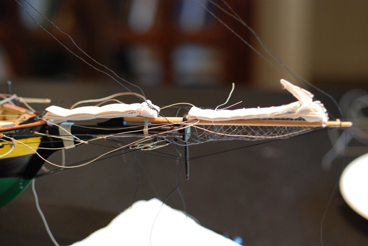
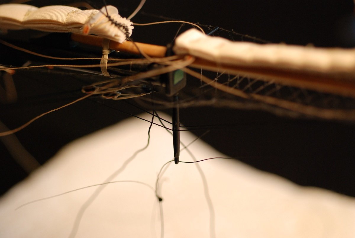
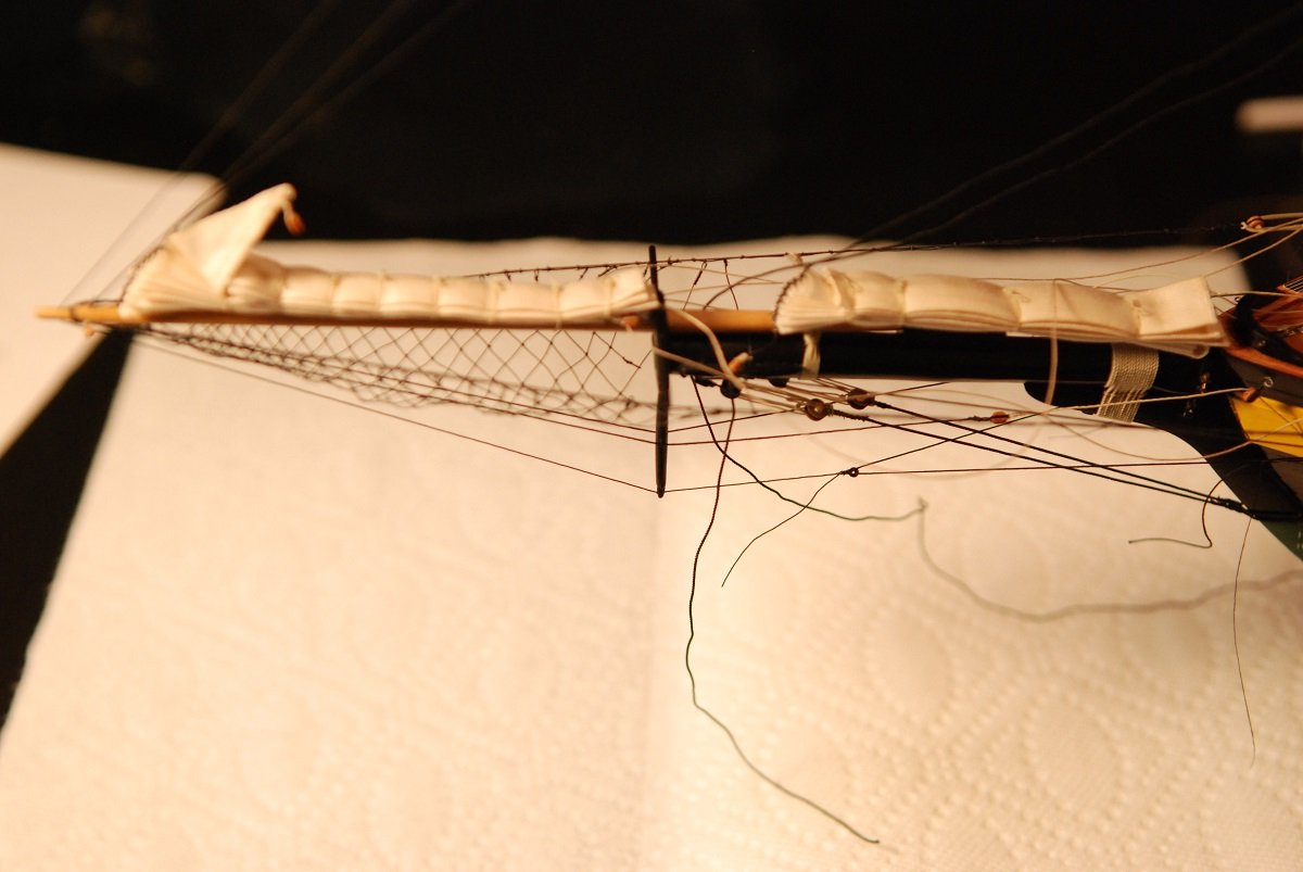
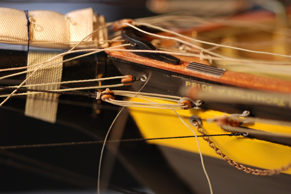
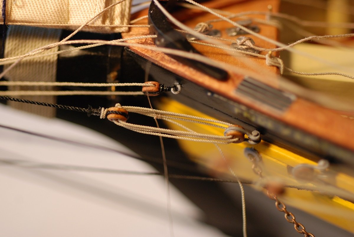
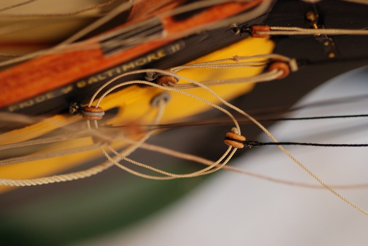
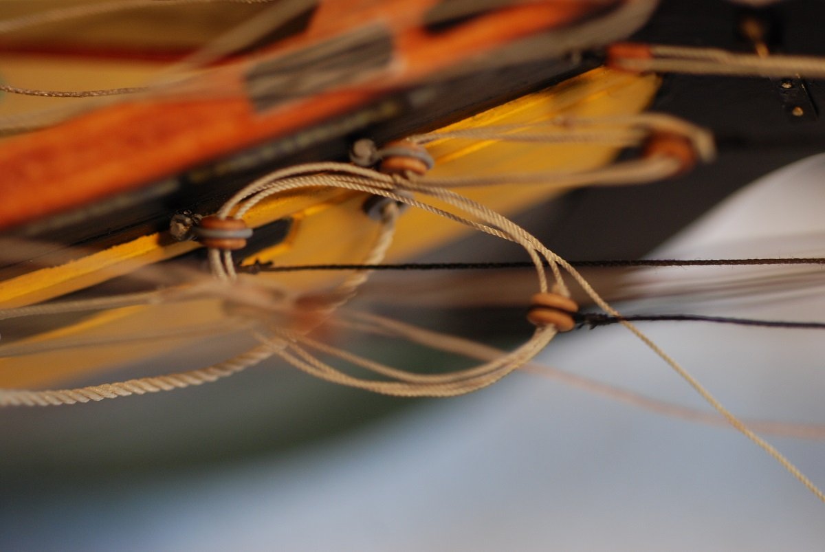
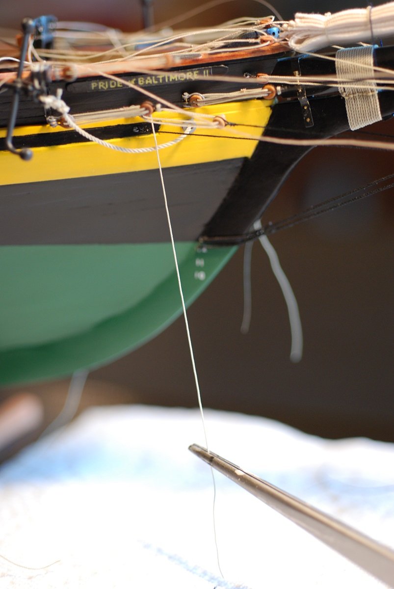
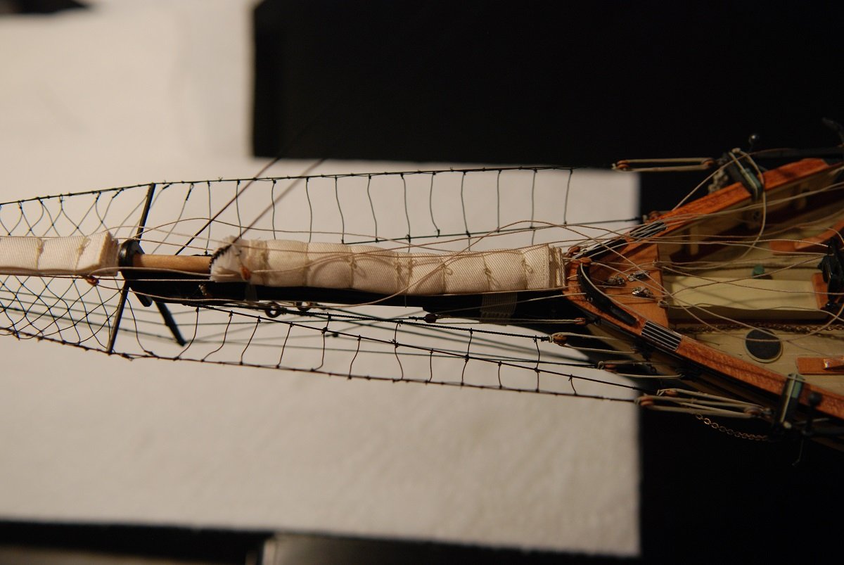
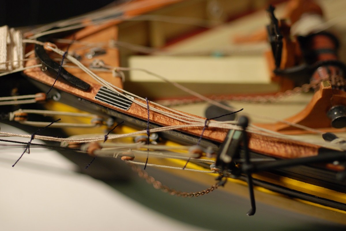
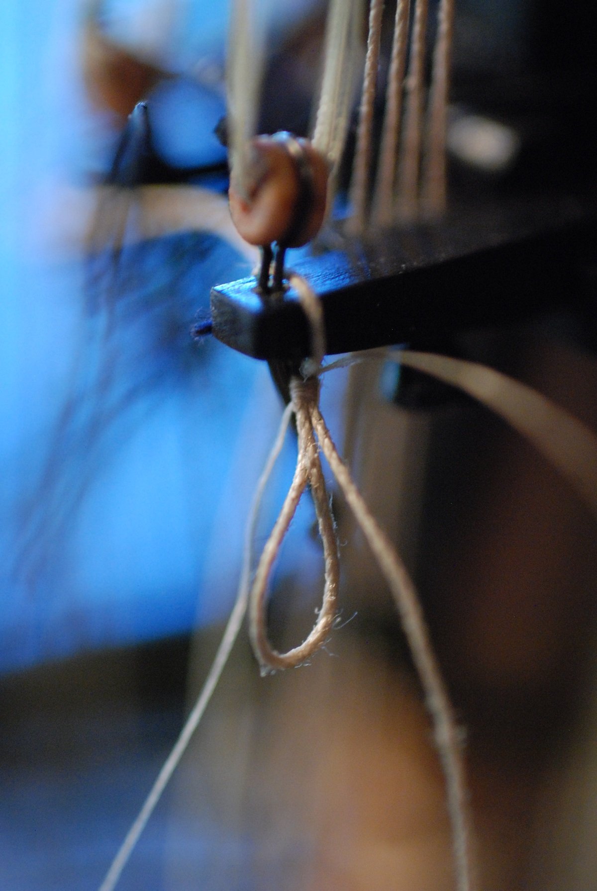
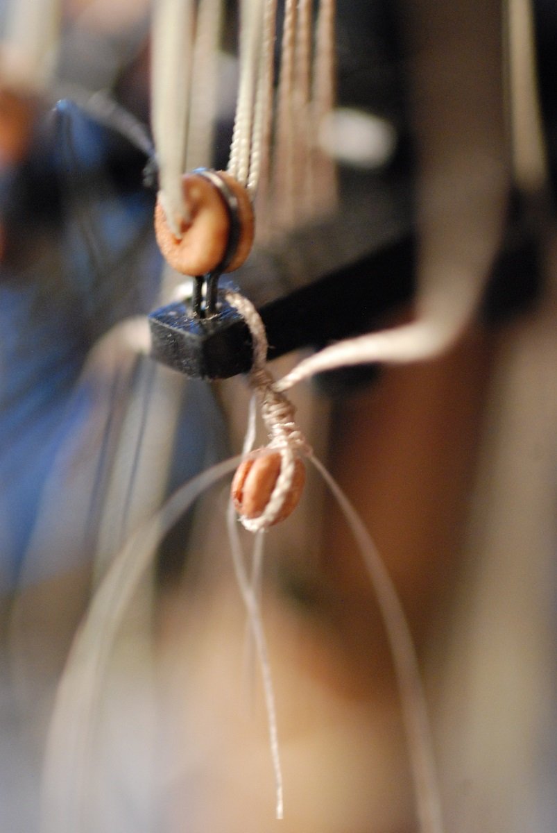
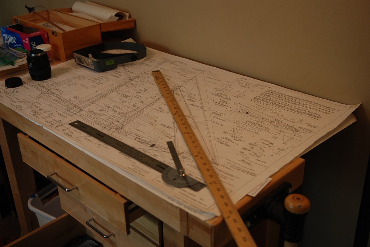
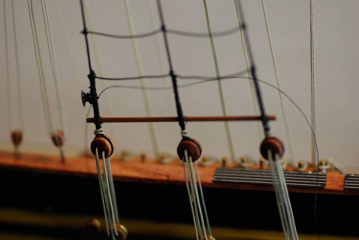
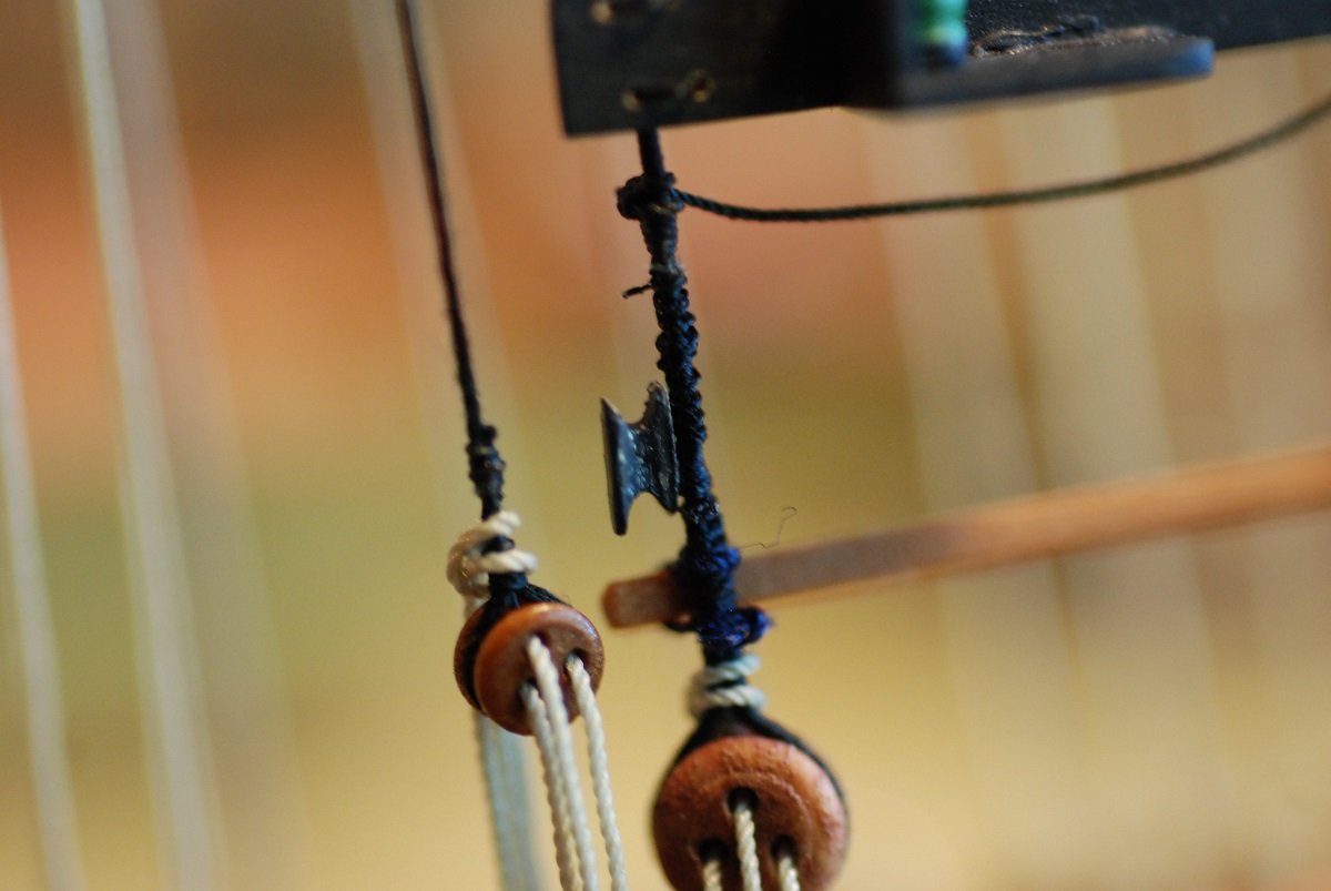
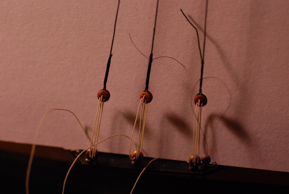
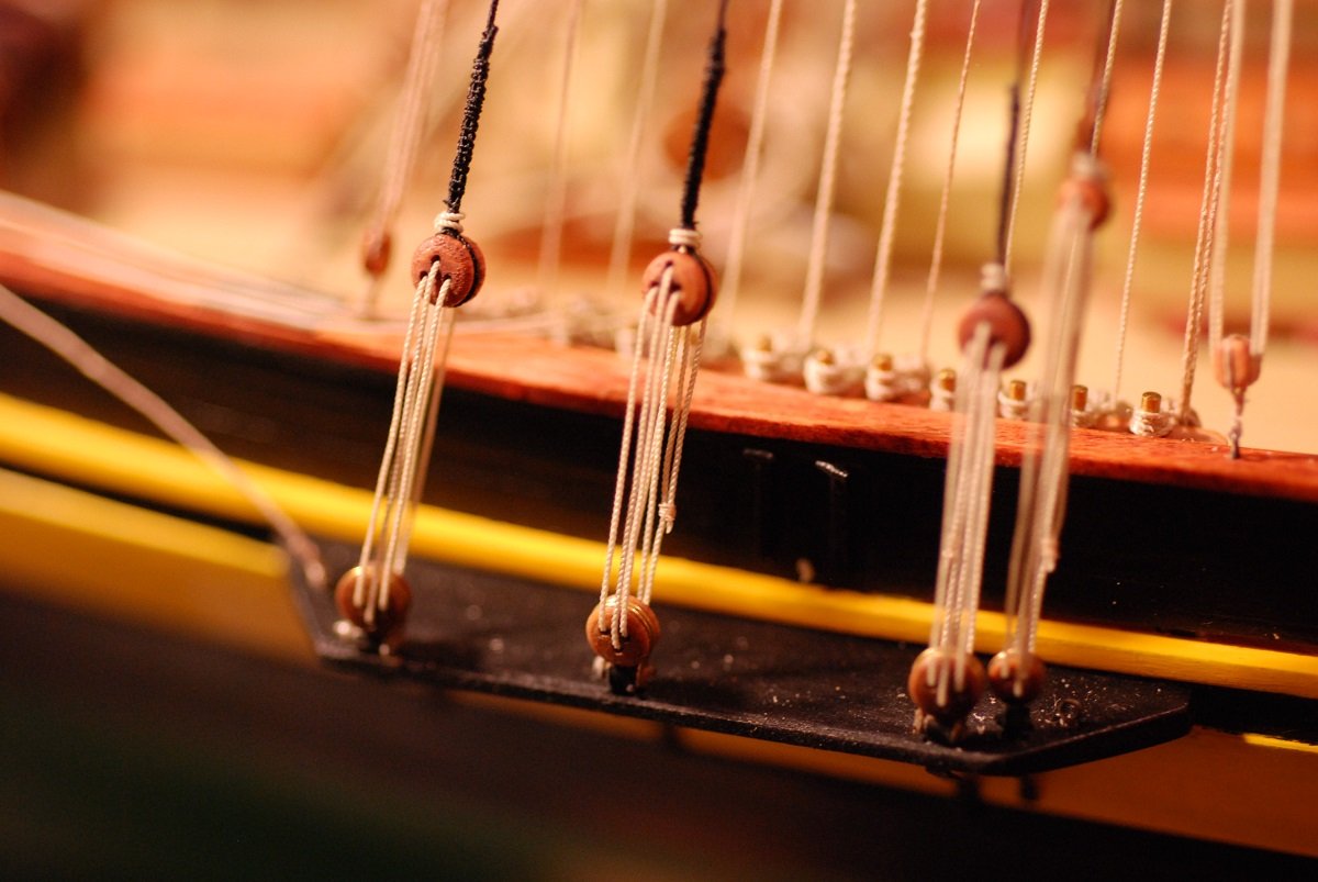
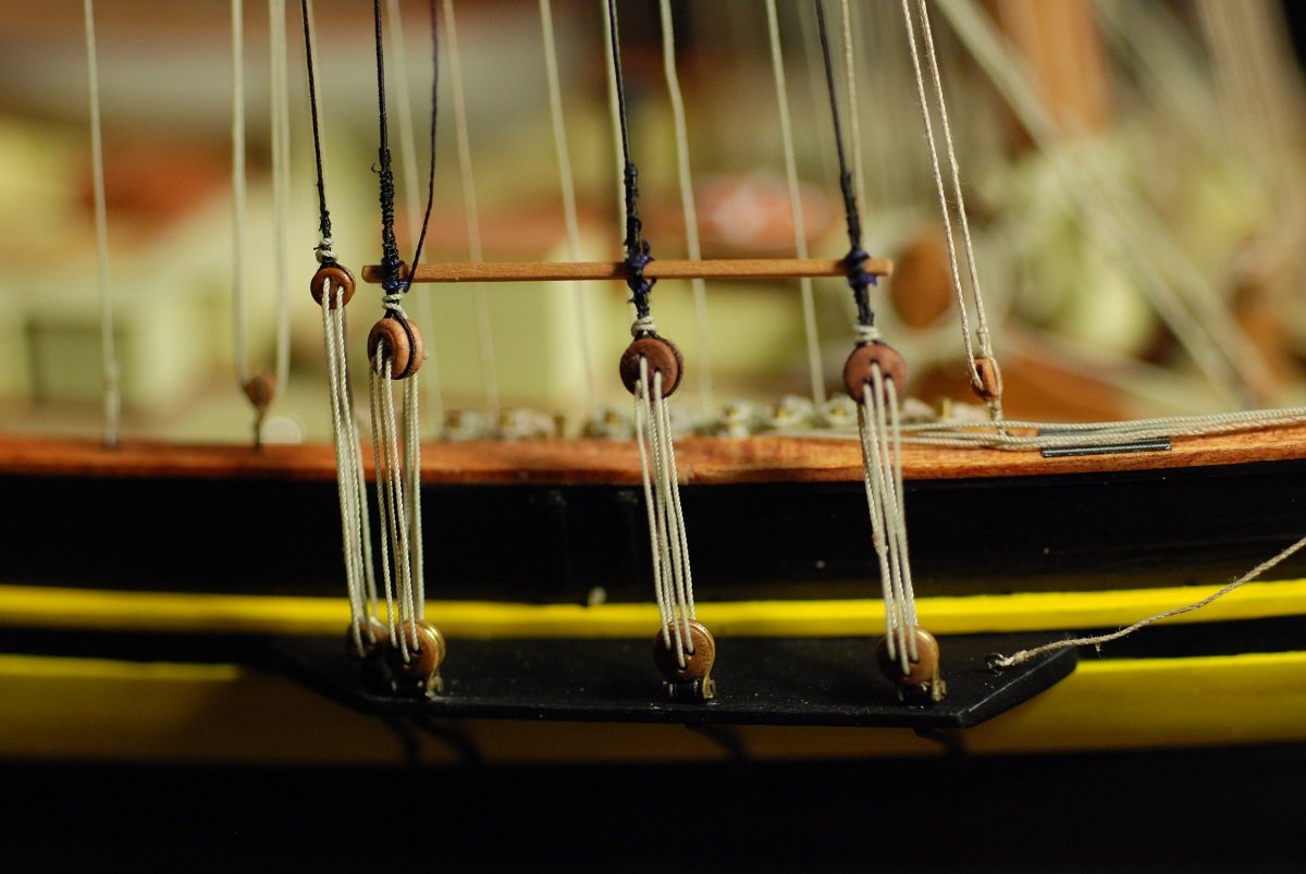
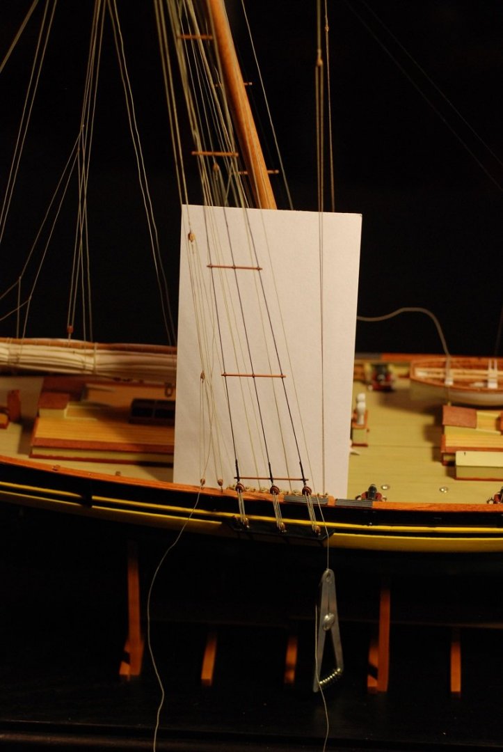
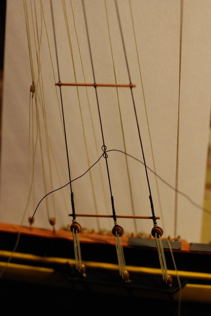
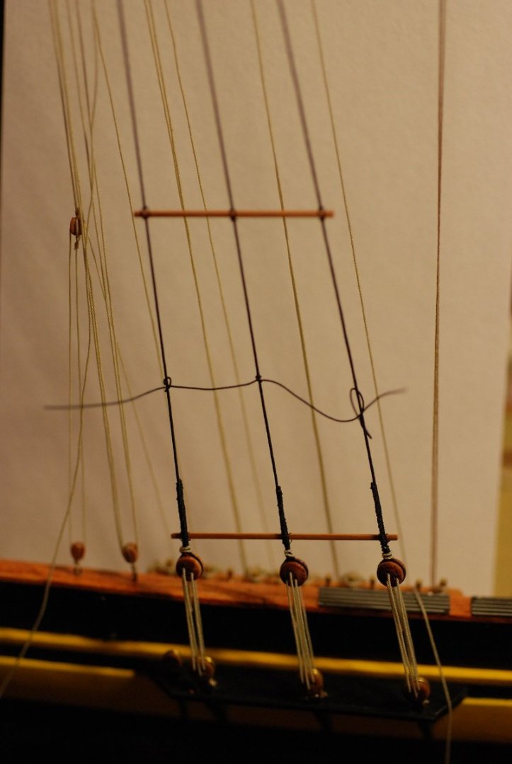
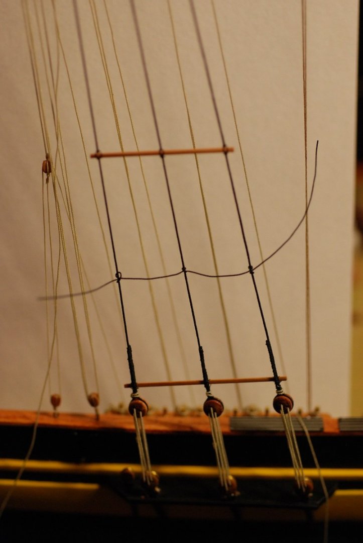
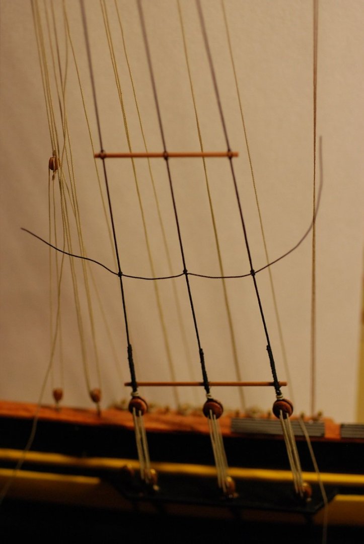
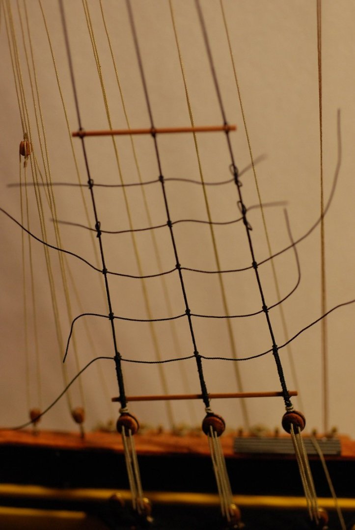
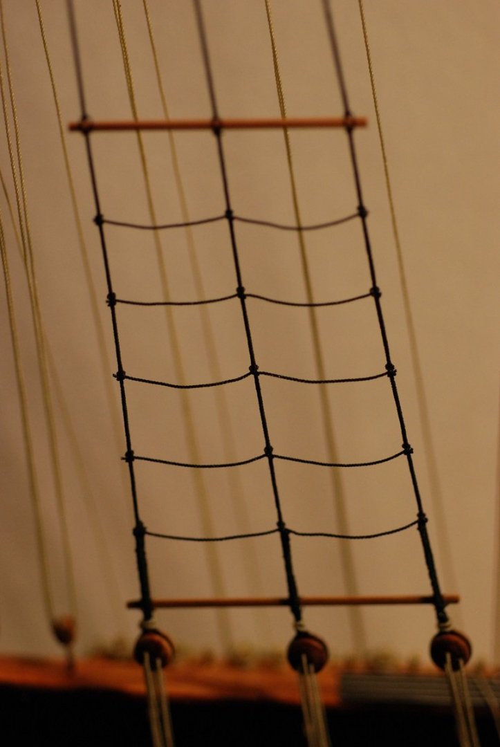
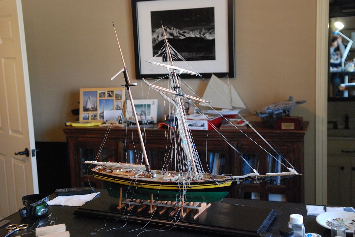
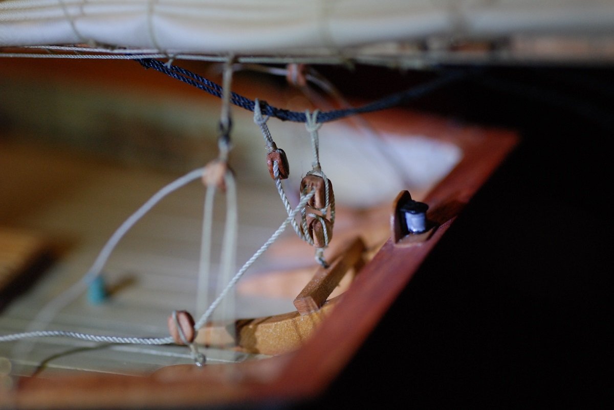
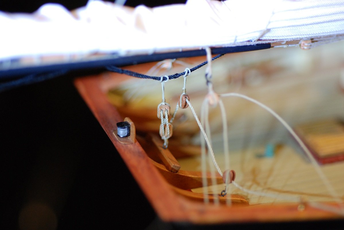
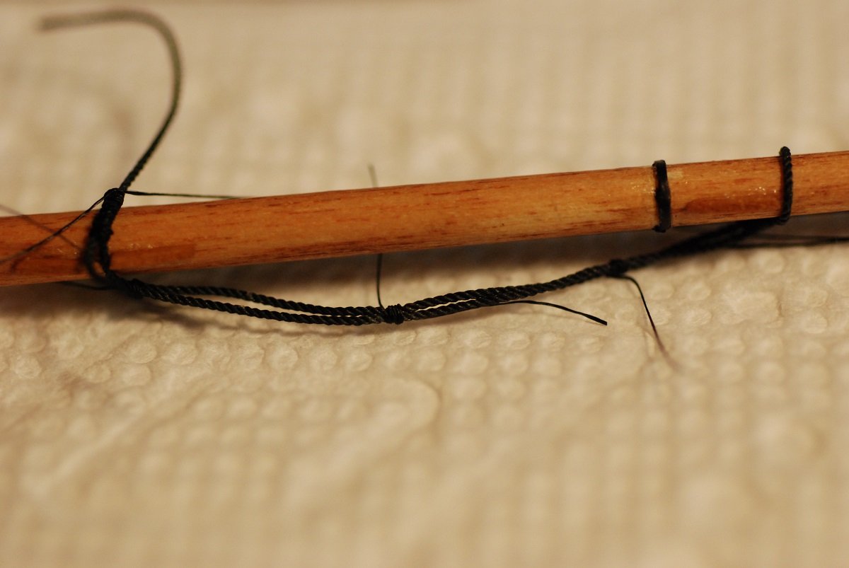
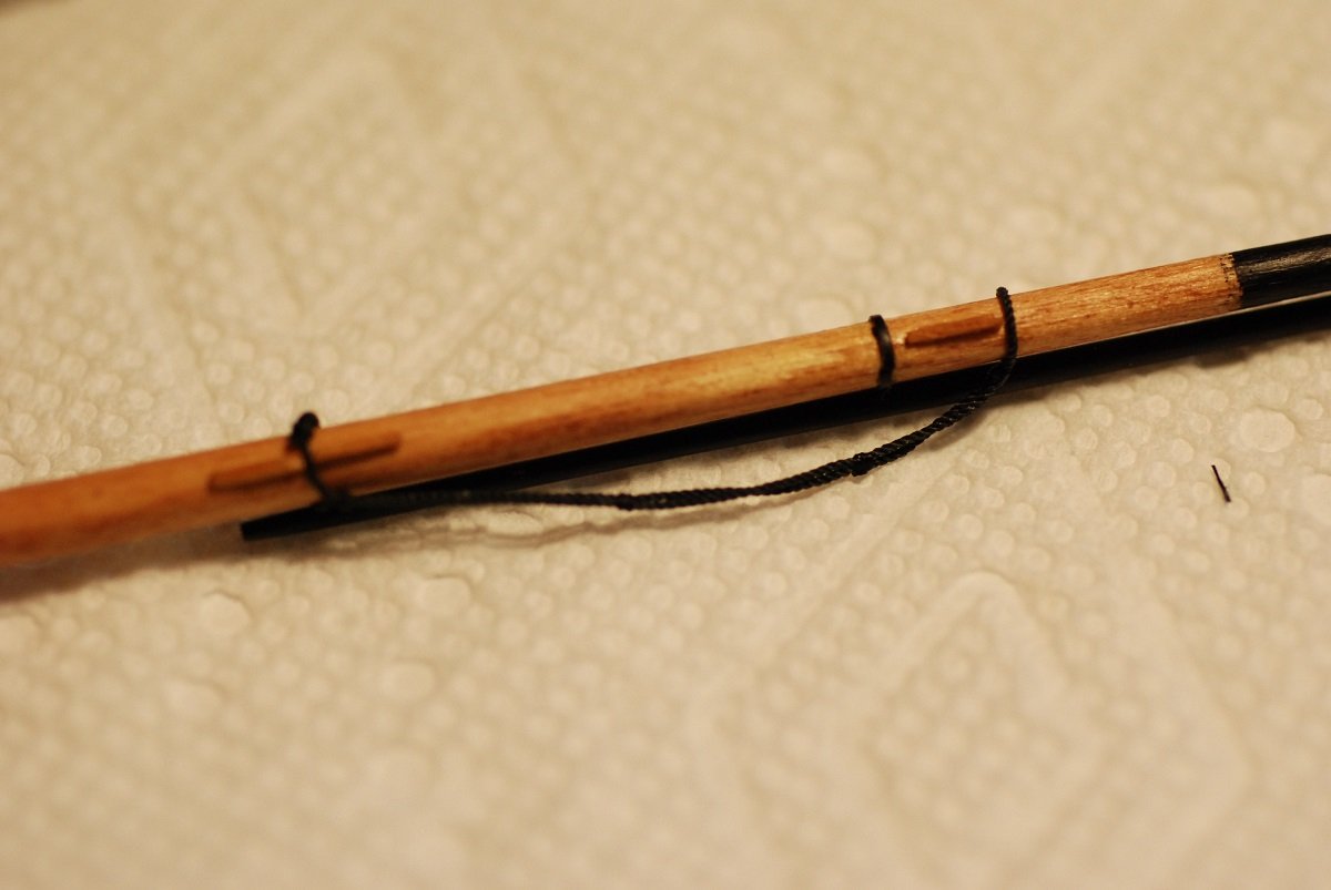
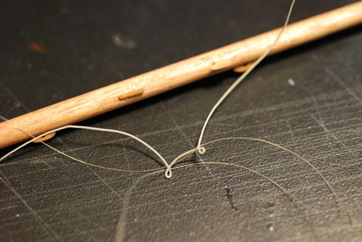
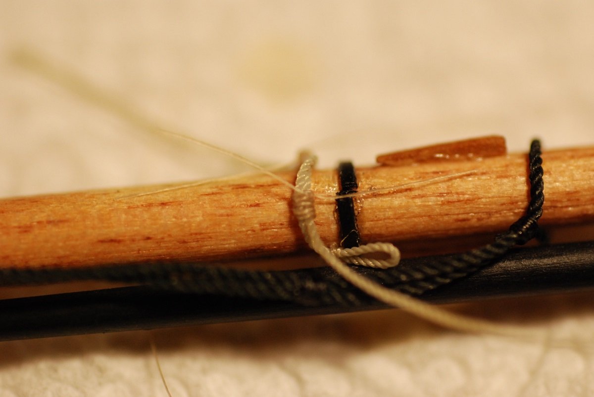
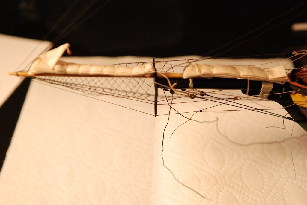
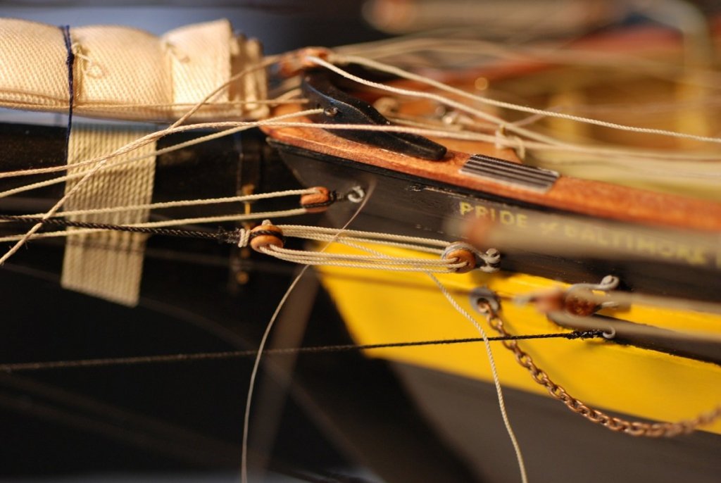
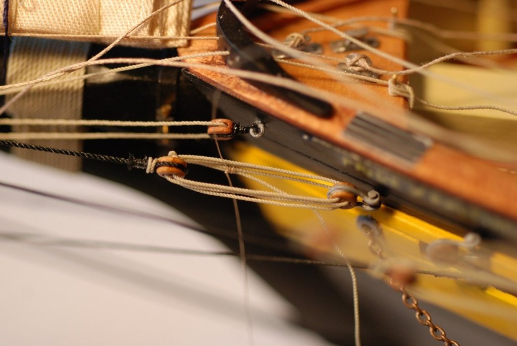
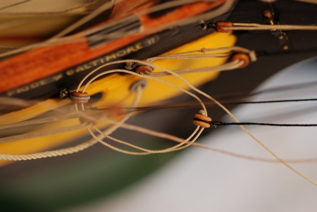
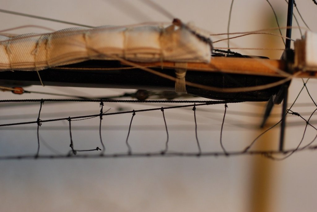
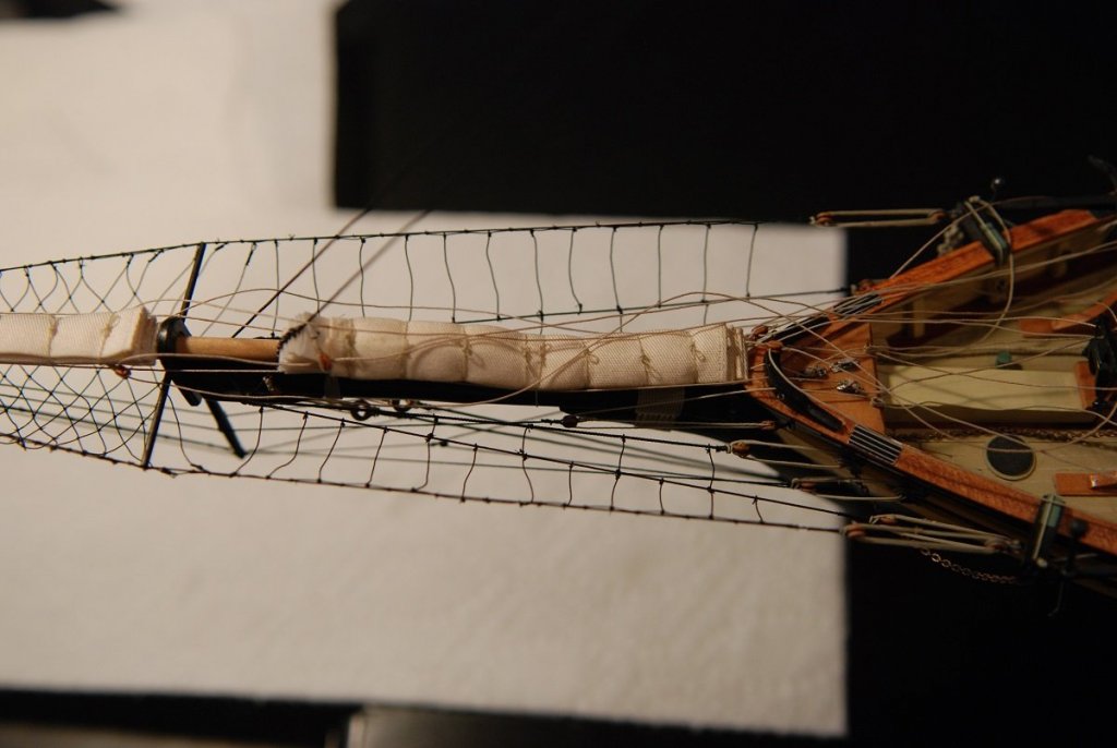
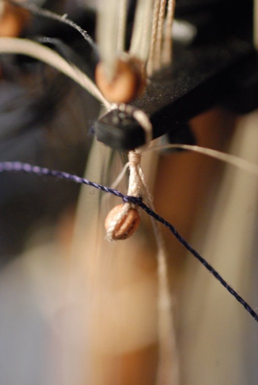
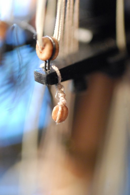
Time to tighten up the various forestays, of which there are five (!). There are two proper forestays, which terminate at the end of the bowsprit. The jib stay, fore topmast stay, and the fore topgallant stay terminate at the very tip of the jibboom. This end of the fore topgallant stay hangs down from the area of the dolphin striker, through which it has to pass before it can be rigged with its thimble. The thimble is then rigged with lines that are secured at eyebolts on each side of the bow (ie, no deadeyes), suggesting that it is not easily adjustable. All of the other fore stays are rigged to deadeyes, allowing for easier adjustment by the crew. The fore topgallant stay can be faintly seen hanging down from the dolphin striker. The jib stay and the fore topmast stay run alongside the dolphin striker. Also visible are the sheets associated with the jib, which run back toward the bow of the ship. The thimble for the fore topgallant stay has been seized, and its control line is threaded through it. The forestay and its thimble are blurry against the background in this photo. The fore topgallant stay has been put under tension, with the control lines running back toward their respective eyebolts. These are the deadeyes for the forestays, port and starboard. This series of pictures shows the deadeyes getting threaded and then secured, with the lanyard tied off with fly-tying thread. Then it’s over to the starboard side, where the corresponding deadeyes are threaded and tightened up. This lanyard is being held under tension in self-closing tweezers that are left hanging under gravity while the slack in the line is taken up and the lanyard is tightened. I had to be careful to make the forestay deadeyes spaced by about the same amount on the port and starboard sides. A detail added at this point was the additional footropes just aft of the bowsprit netting, on either side of the bowsprit. As mentioned before, the control lines for the headsails run back toward the bow, where they are tied off at the fore pinrails. These lines were laid out, then some disposable black thread was used to roughly secure them in the desired locations. They were then wetted with dilute glue to keep them in place, and to keep them from standing up against gravity. You can see some of the temporary threads securing the headsail sheets. Blocks for the jib halyard then were installed at the trestletrees of the foremast. I found that for rigging blocks, I liked using the Syren line. But when it came to the running and standing rigging itself, I preferred the appearance of Morope. (Sorry, Chuck…) This loop has been tied off with nylon fly-tying line. Some disposable black thread holds things together while the block is secured in place with more fly-tying line. These two particular blocks (one on each side) are rigged with a short pendant, so this took quite a few wraps of the fly-tying line. Now we are reaching the point where I have to secure the foresail gaff. But at what angle? Here is my protractor being used to estimate the angle of the gaff from the plans. And so the peak and throat halyards were tightened, and the gaff’s vang lines were installed so as to duplicate that angle. The vang lines are currently hanging free from the end of the gaff. We haven’t reached the point of snugging everything up at the pinrail yet, but it was at this point that I realized how excessively I had waxed some of the lines. The flakes of wax required careful cleanup, and from this point on, I didn’t wax any more of the running rigging. From left to right, the lines that have been belayed are the jib sheet, jib halyard, staysail sheet, lower yard lift, lower yard truss, foresail peak halyard, and foresail throat halyard. It may not look like it, but the foremast installation is essentially complete. Final tightening of the associated lines would wait until the mainmast installation started, because some of these mainmast components would need to be in place in order to allow final adjusting of the foremast rigging. So next up, moving on to the main mast!


- 60 replies
-
- 5
-
-
- pride of baltimore ii
- Model Shipways
- (and 1 more)
-
Question about table saw technique
jdbondy replied to jdbondy's topic in Modeling tools and Workshop Equipment
No, using Chrome. I am not too worried about the problem; it just seems to come up every once in awhile. Usually I just retake the picture, downsize it again, and it will work fine. -
Question about table saw technique
jdbondy replied to jdbondy's topic in Modeling tools and Workshop Equipment
Yeah Mark, I checked that, and the picture has been reduced to appropriate pixel dimensions. But it still won't load. This seems to happen to me occasionally with a random picture. Haven't made any sense of it yet. -
Question about table saw technique
jdbondy replied to jdbondy's topic in Modeling tools and Workshop Equipment
Dave, Mark, Vossiewulf, thanks for the feedback. Today I made a quantum leap in my table saw technique. I have installed the splitter and created a push stick. Each enables a much smoother pass of the wood through the blade. Unfortunately, my picture of the stock boxwood and the sheets I created is failing to upload. However, I experienced no binding of the blade when I was able to push the wood at a very consistent speed through the blade. I used each technique, one in which the sheet was created from the wood between the blade and the fence, and one in which the block of wood was pushed between the blade and the fence, with the sheet falling away to the left of the blade. Each worked equally well. I am finding the key is the smooth passage of the wood through the blade, at a speed that "lets the tool do the work". (Where have I heard that?) To which probably a lot of you will say, "Uh, yeah, just now figuring that out??" But I feel proud of having learned the lesson nonetheless. Sure wish my photo would upload...I get an error dialog box, and all it says is "-200". -
Question about table saw technique
jdbondy replied to jdbondy's topic in Modeling tools and Workshop Equipment
Regarding my secondary issue described above where the motor slows down and the width of the cut increases, I have made a zero clearance plate with splitter out of cherry wood. The problem has improved but is still present, so I plan on adding a little bit of width to the splitter and hopefully that will resolve things.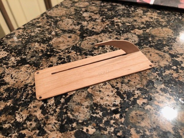
-
Admiralty model query
jdbondy replied to iMack's topic in Building, Framing, Planking and plating a ships hull and deck
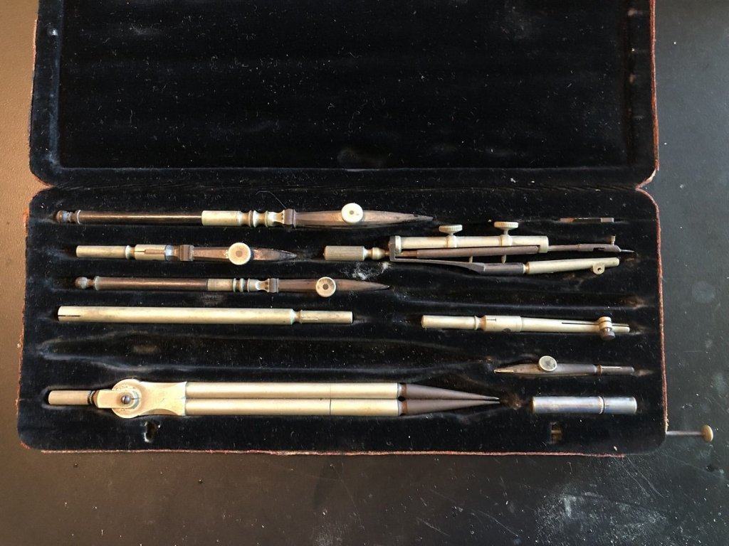
Bob, I owe you a big thank-you. Your picture of the Keuffel and Esser instruments jogged a memory, and I checked with my mother, a pack rat who moved to the US with her family in the early 1950s. She was a medical illustrator and her brother had done some drafting work. She may be a pack rat, but she knows just where to go find it when I ask about something. A phone call produced this: The brand on the case is Staedtler, made in Germany. She also has this: The brand name on the case for this one is Riefler Nesselwang. She estimates this one may be substantially older than the first set, as it was used by her grandfather. Each set demonstrates corrosion. Any suggestions on who to start checking with on getting them cleaned up? My thought goes to my local Asel Art Supply store to see if they have suggestions. So glad I saw your post!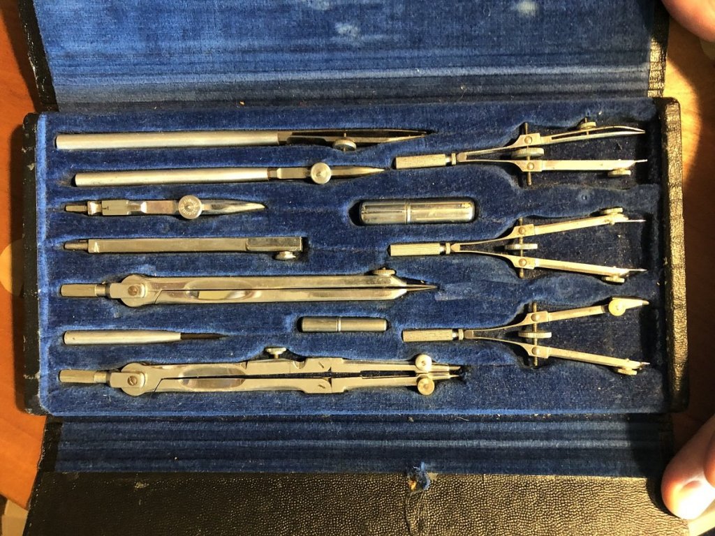
-
Question about table saw technique
jdbondy replied to jdbondy's topic in Modeling tools and Workshop Equipment
I'm not using the slitting saw blade, I am using the heavier duty blade that I presume is the carbide blade. -
Admiralty model query
jdbondy replied to iMack's topic in Building, Framing, Planking and plating a ships hull and deck
I started perusing this thread because I have been looking for a tutorial on how to properly use ships curves to join points smoothly. In the past when I tried using them, I ended up with some very un-smooth curves that were composed of several curves of different radii. Any suggestions? -
Question about table saw technique
jdbondy replied to jdbondy's topic in Modeling tools and Workshop Equipment
Follow up question for you all: When I try to part off a sheet, whether with one pass or two, no matter how slowly I push the board through the blade, there are moments when I can hear the resistance building and the kerf of the cut widens by a small amount. Then the resistance releases, the board pushes more easily, and the cut returns to the narrower width. Is the blade getting clogged by sawdust within the cut? Why does the cut widen? When I do the cut in two passes, the depth of cut is 3/8". I have tried doing some cuts with one pass, meaning I am cutting a thickness of 3/4". I am beginning to think I am asking too much of the tool. -
I am parting off some 1/16" thickness sheets from some boxwood stock that is 1/2" in thickness using the Byrnes table saw. Is it frowned upon to part off the sheet using two passes, one on each side of the sheet? It seems to be a safer way to do the cutting since the saw blade can be left at a height of just over 1/4" and it remains covered by the wood stock while making the cuts. Thanks for any guidance!
-
Warped frames
jdbondy replied to jdbondy's topic in Building, Framing, Planking and plating a ships hull and deck
My wife points out that my frame press is way more expensive than the one from Harbor Freight... -
Warped frames
jdbondy replied to jdbondy's topic in Building, Framing, Planking and plating a ships hull and deck
Here's my next-generation framing press: It is made of all those books I haven't looked at since medical school and residency! Beneath them, the frame is compressed between two 1/8" sheets.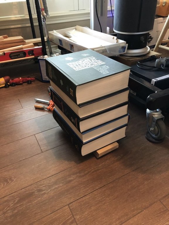
-
Warped frames
jdbondy replied to jdbondy's topic in Building, Framing, Planking and plating a ships hull and deck
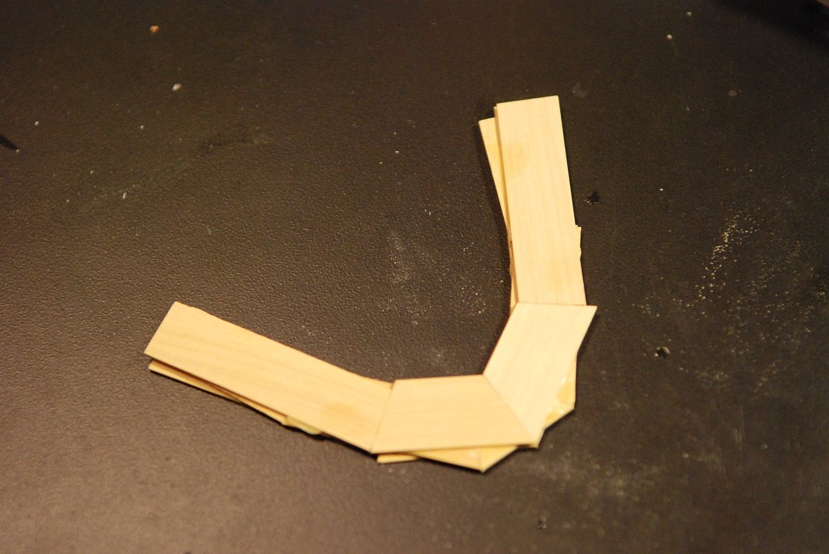
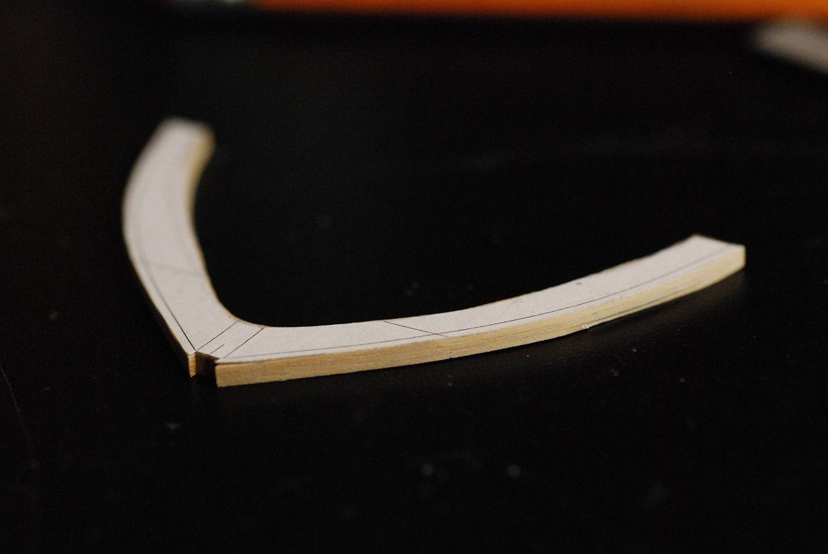
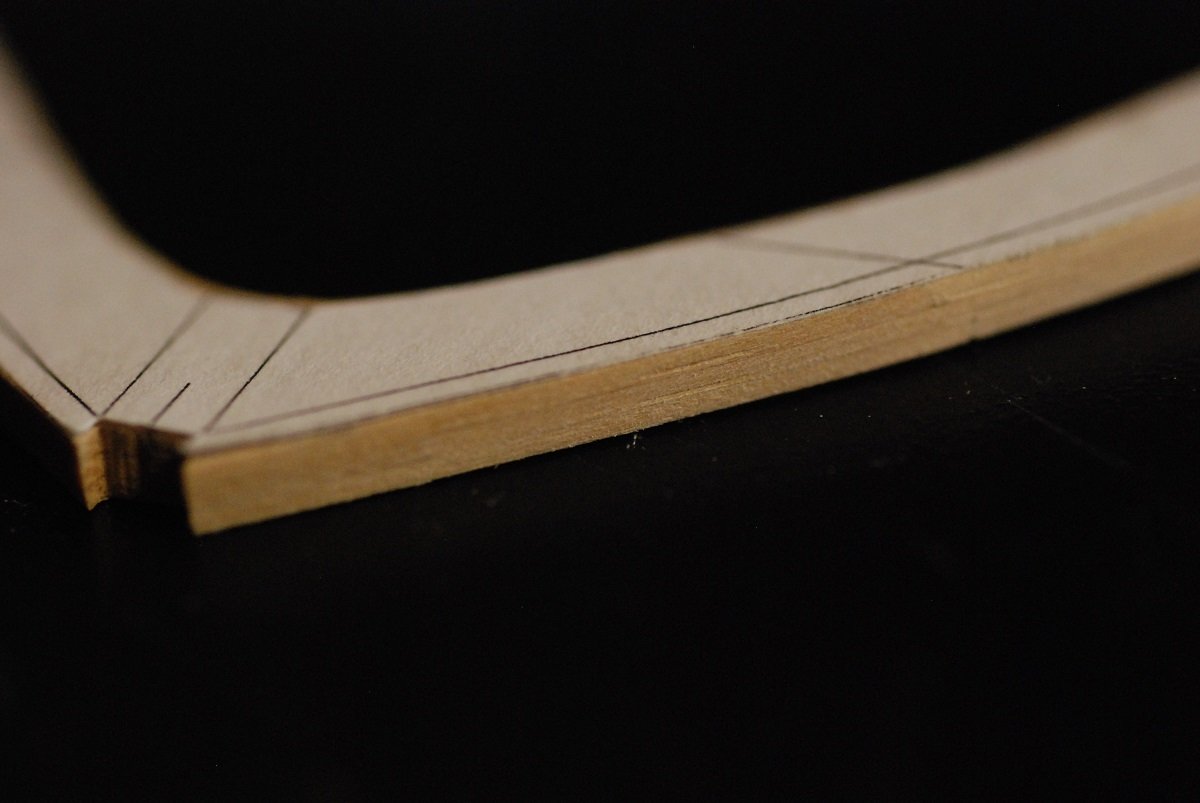
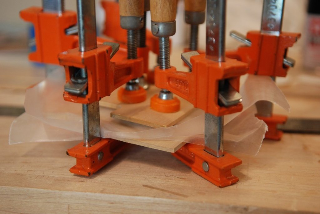
For better or for worse, I have solved my warped frame problem. I created one example frame to test the idea of using 3 layers of 1/32" boxwood. Mark, the 3 layers were composed in the same way as you assembled the patterns for your frames: While still wet, these were put between pieces of 1/4" basswood sheets, which were then clamped: A very flat frame was the end product: A close-up shows the 3 layers laminated together: So like I said, for better or for worse, looks like I have a solution. And this example is really strong. Do I really want to pursue this route? I don't know... Thanks for all the guidance!


-
I'm so sad now that this journey is over! Guess I will have to find someone else's log to follow... Congratulations, Toni!
-
Warped frames
jdbondy replied to jdbondy's topic in Building, Framing, Planking and plating a ships hull and deck
Mark, I will be sure to look at your Licorne build. In fact I may have perused it before. My frame thickness would ideally end up at 3/32", so less than half the thickness of your frames. That's a big part of the problem I am struggling with. But it is fun to experiment with the different possible solutions to the problem: two layers vs three, wood glue vs epoxy, etc. I expect to learn some important lessons by the time I find a solution.