HOLIDAY DONATION DRIVE - SUPPORT MSW - DO YOUR PART TO KEEP THIS GREAT FORUM GOING! (Only 13 donations so far - C'mon guys!)
×


jdbondy
-
Posts
340 -
Joined
-
Last visited
Content Type
Profiles
Forums
Gallery
Events
Everything posted by jdbondy
-
 Hey Maury, I am glad I have happened across your build. It's my own fault for not finding it sooner! Will review your progress so far. You may remember that we are virtual neighbors: I am over in north Dallas.
 -
Very lovely but I would never ask someone to make such a sacrifice! Aber vielen dank! JD
-
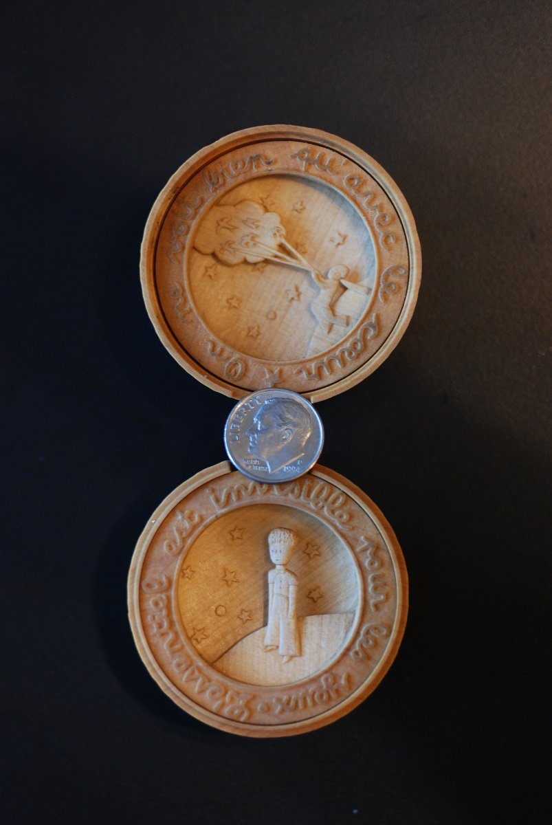
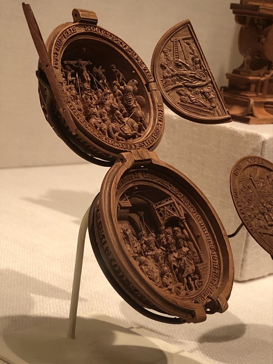
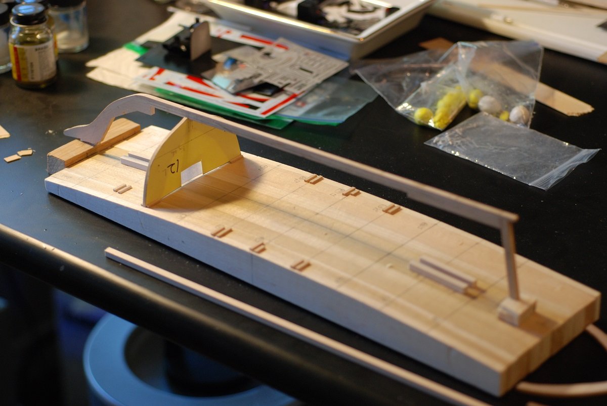
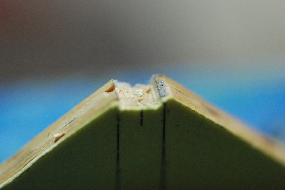
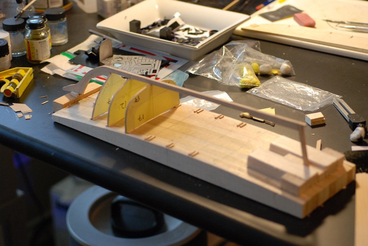
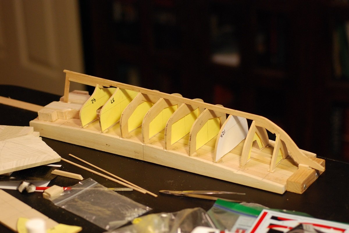
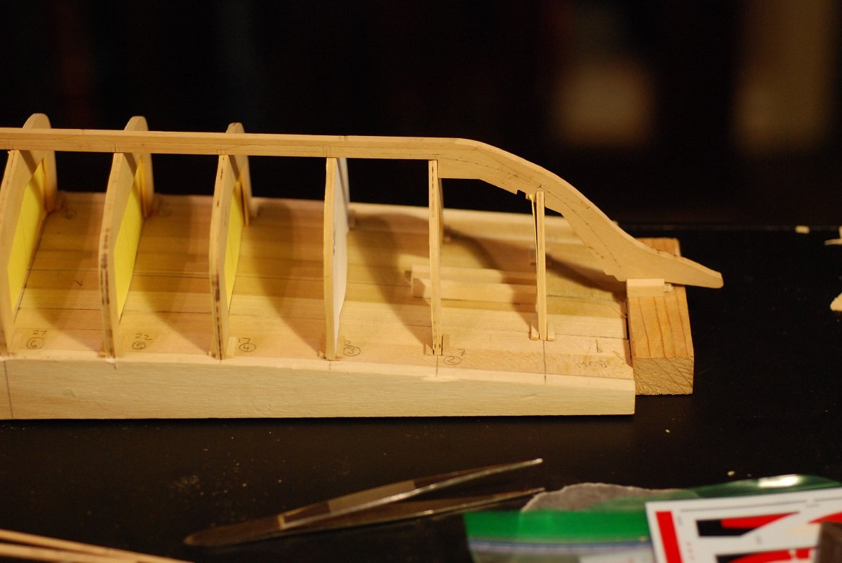
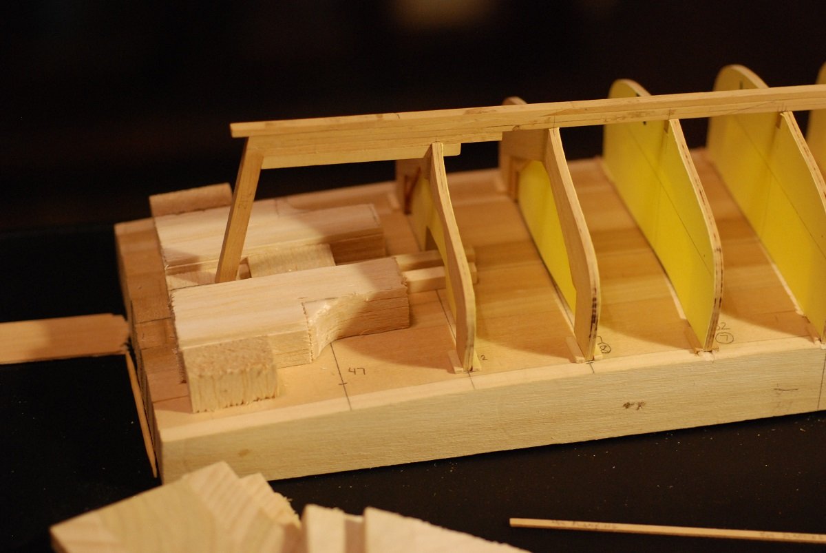
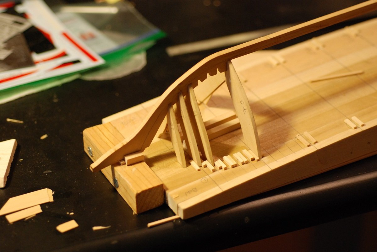
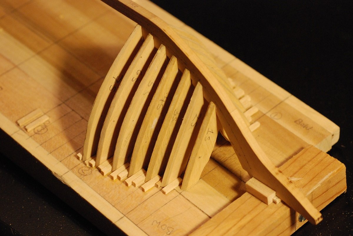
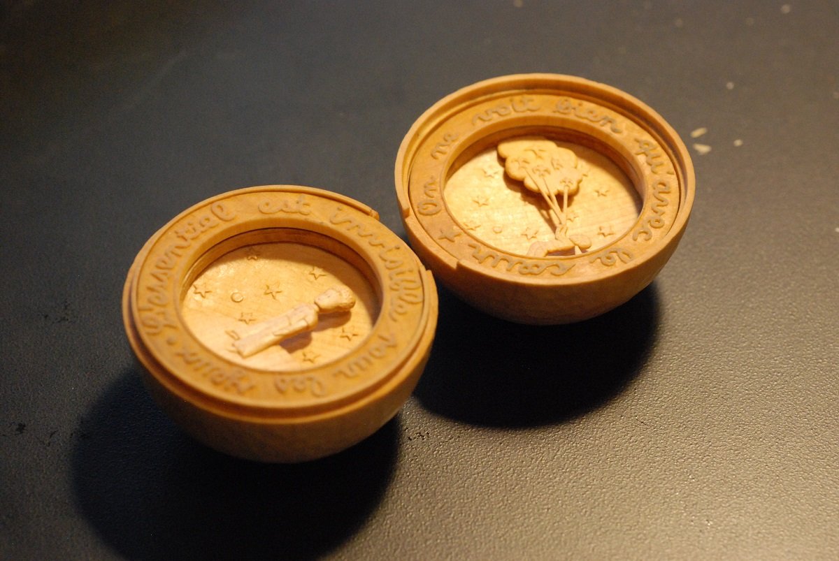
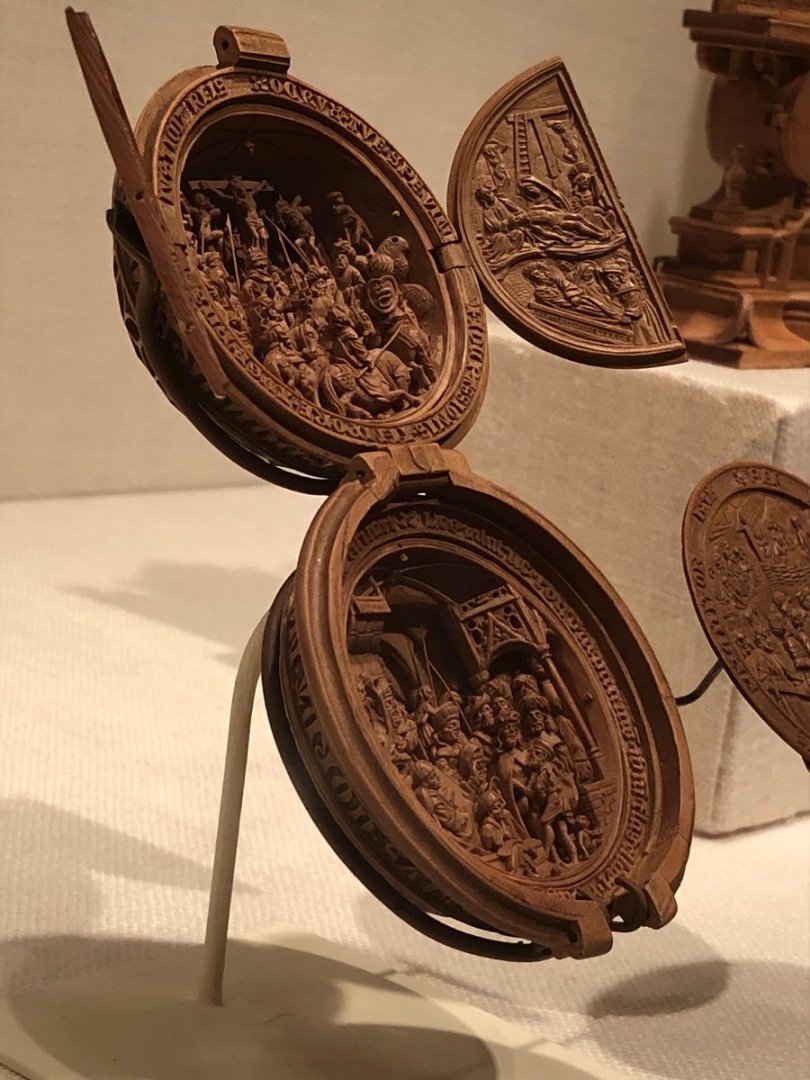
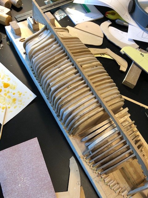
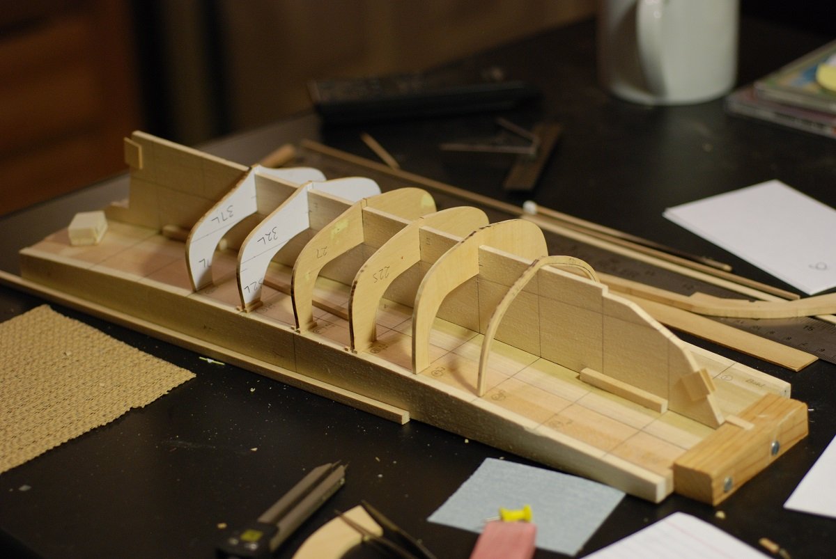
In my previous post, I was musing about future directions for the model. In particular, wondering about how faithful to be to the actual structure of the schooner. If I were to just plank over the frames (bulkheads, really), then I have already gone above and beyond in creating all these bulkheads. But to take full advantage of the work I have done so far means leaving at least part of the hull unplanked, in order to show off the framing pattern. I am leaning toward leaving part of one side unplanked, and in that area making sure that the visible frames are ones made of boxwood, rather than the 3/32” Baltic birch ply that I started using more frequently. Fortunately, nearly all the frames forward of the greatest beam are boxwood frames, so it is reasonable to think of just leaving a portion of bow planking off on one side of the boat. I am going to proceed as if that is the plan. In the picture above, it’s possible to distinguish the boxwood frames from the plywood frames. Plywood frames are visible in the area of maximal beam, and there are more of them headed off to the stern. In between the frames, I have created basswood inserts that are smaller than each of the frames. I envision having these in place for the fairing process, as I get the shape and bevel of the outer surface of all the frames worked out. I am going to rewind a bit, to the process of fitting each frame to the keel and baseboard. The first frames to cut out and size up were the frames at the station lines. Four intermediate frames are found between each of the station frames; those will come later. It took some time to figure out a good method for cutting the keel notch to the appropriate width and depth, with clean corners so that each frame would articulate properly with the keel. The best method I have come up with is using an X-acto knife to first cut out an appropriate width from the paper template glued to the frame (not shown in this particular case), and while doing so, make a tiny cut in the edge of the frame in the area where the notch is supposed to be. Then I extended that cut carefully across the width of the frame, then gradually cut into the frame vertically at the edge of the notch-to-be. Then I used the X-acto knife to work into each corner, and then trim out the floor of the notch between the corners to a level surface. I initially did not realize how crucial a process this would be. It was only when I started to consider how the planking would have to come down the surface of the frame and fay smoothly into a rabbet that I realized that I had to make the depth of that notch of just the right depth so the surface of the frame flowed into the rabbet. Only after that was done could I consider trimming each frame/bulkhead at its upper surface, in the area of the bulwarks and caprail, so that each frame would fit into the space allowed between my baseboard and the keel on top of it. At this point, the keel does not have a rabbet cut into it, but the rabbet line has been transferred to the keel. I was able to use a sample piece of wood of appropriate thickness (3/64”) to make sure that I had the depth of the notch about right. Each of the frames here have had a notch cut into them, and in the case of the forward-most and aft-most station frames, notches have been cut in the stem assembly and deadwood, respectively, to receive the frames. You can faintly see the rabbet line penciled in on the stem and keel in this picture. The deadwood hasn’t been fully built up onto the keel yet. Since I had already done some work pre-beveling the first seven frames, I went ahead and worked on cutting out notches in the keel to receive frames 1 through 6. As you can tell, it was a challenge getting the spacing of the notches exactly right. The third notch is too far forward; I fixed this by extending the notch further into the keel and making sure the extension was more properly spaced. In addition, I glued shims to the baseboard to receive the uppermost surfaces of the frames. Due to the slant of the baseboard in this area (mimicking the upward slope of the caprail), the uppermost surface of each frame had to be beveled accordingly. Frames 1,2,3, and 7 in place. Cutting the depth of the notch in each frame here was crucial in order to make sure the bottom edge of each frame was spaced far enough from the rabbet line to allow for the cutting of the rabbet later on. Frames 1-7 in place. I will probably need a filler block forward of frame 1. This brings us to July of last year. At this point, the model went on hiatus, and that is entirely the fault of my carving teacher and a mutual friend, who made me aware of Renaissance prayer beads made of boxwood, depicting ornate scenes from the Bible, such as seen below: Which got me to thinking. My wife is a French teacher, and every year she and her students read The Little Prince by St. Exupery. An idea of a Christmas gift formed in my mind, and the next half year was spent constructing a (much simpler) boxwood sphere meant to represent one of the planets from the story, with (much simpler) scenes from the story on the inside of the bead. The hinge hadn’t been installed yet at the time of this picture. The sphere is about the size of a golf ball. I am happy to report that the gift was well received, and I was able to move on and get back to model ship building! Except, now the little planet needs a stand to rest on…OK, maybe I will work on carving a stand when I take breaks from model ship building. At the time of the next post, we will pretty much be up to real-time status.


-
Did I miss something? You painted all those friezes since your last post? Wow!
- 221 replies
-
- 1
-

-
- queen anne barge
- Syren Ship Model Company
- (and 1 more)
-
Still looking for someone who can tell me about how molded dimensions of individual frames were calculated...
-
Been doing pretty well with quartersawing these holly logs. Do I need to go out of my way to remove or avoid the pith, or is the pith something that will become obvious once the wood has dried? I am told that any residual sapwood on the outside surface of the slabs will just flake away, so I am not worried about that part.
-
What kind of paint are you using, and primer if applicable? I agree, painting is one of my least favorite parts of model building!
- 221 replies
-
- 1
-
-
- queen anne barge
- Syren Ship Model Company
- (and 1 more)
-
Edward, when you notice that a neighbor has cut down their Buxus sepervirens, please let me know and I will come across the pond to get some!!
-
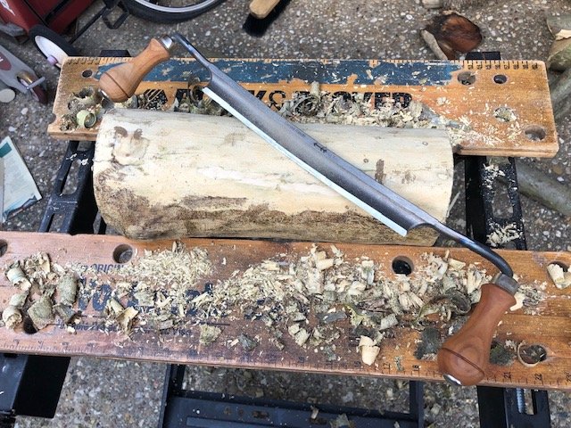
Oh, and I almost forgot: check out my new toy! A Swiss drawknife!
-
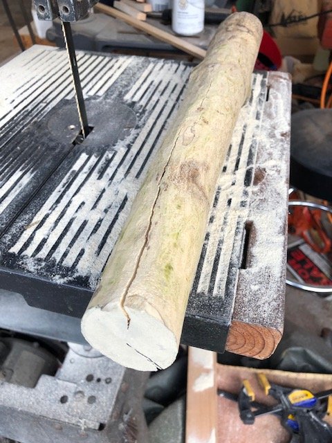
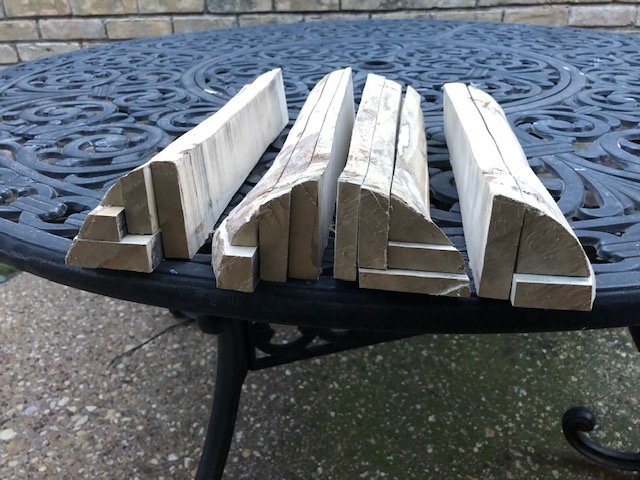
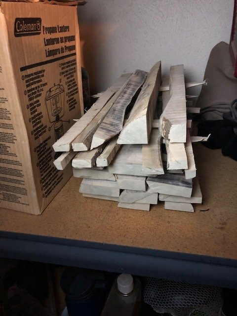
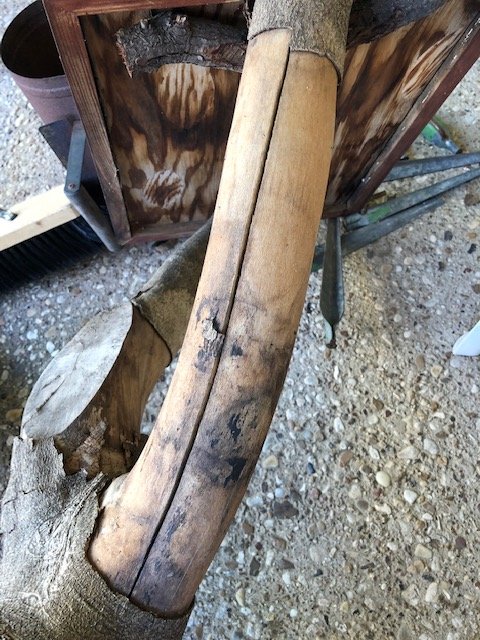
I got to the bandsaw tonight with a 12 inch log of about 4-5" diameter, and a smaller one about 2-3". The smaller one already has a big check in it: But I cut it up to get flitches of about 3/8" thickness. How's this for a first attempt at quartersawing: These pieces are 1/2" to 3/4" in thickness. I took what the bandsaw would give me. My technique needs work; the pieces are of variable thickness due to difficulty controlling the log against the fence of the bandsaw. I forgot to finish cutting one of the corner pieces on the right. My kiln! AKA a shelf in the garage. I am gonna need A LOT more space. There is a lot more wood to come, including pieces of 24" length.
-
Keith, I love the gilded cage that is my workshop! OK, we have to talk. The moment I received the builders plans for the Mary Day, I had envisioned building a model that was a true reflection of the way in which the Mary Day was constructed. After all, I have all this information. May as well make the most of it. So to do that, I would have to accurately craft a keel to serve as a backbone. I would then need to create 51 sets of frames, whose shapes are determined by a 3D reconstruction of the model so as to obtain frame shapes that lie between the eleven stations that are detailed in the lines drawing. These 51 frames would of course need to be accurate in their outer shape, but then also they would need to be accurate in terms of their width (molded dimension) as they travel from the keel up toward the sheer and the caprail. They would also require accurate cutting of a notch where they articulate with the keel, so that their shape flows accurately into a rabbet carved into the keel. Since each of these frames would then be quite fine in dimension, they would have to be composed of strong and stiff material, and be dimensionally stable. (There must be some traditional way of determining what the molded dimension of a given frame should be, but I haven’t yet found anyplace where that is described. If you know what it is, please let me know!) But…do I intend to fully plank the model? Why go through all that work if it is just going to be covered up? If I do plan to fully plank the model, shouldn’t I just stick with the 11 stations, and forget about creating all 51 frames? Is there a middle ground, where I do use all 51 frame stations, but don’t worry about milling each frame to its true molded dimensions? In fact, I have already done a lot of the work toward creating 51 frames. So I have not yet crossed any Rubicons that would keep me from moving forward with a traditional build. (Except that some of the frames I recently cut out were made from 3/32” Baltic birch plywood, instead of the laminated boxwood that I used prior to learning about Baltic birch ply.) Fortunately, at this particular point, there is still a lot of work I can do prior to having to make the decision on how accurate a construction to use, and on whether to, say, plank only one side of the model. I still have to create a few more frames. I have to mark all the frames up for the waterline, sheerline, and planking bands. I still haven’t finished carving the rabbet, and I need to create filler blocks for the bow and stern after finishing the rabbet. Then the outer surfaces of the frames would need to be faired to their final shape before I would consider removing any material from the inside of the frames. To aid in the fairing process, the spaces between the frames on the baseboard are filled with 3/16” thickness pieces of basswood, to stabilize the whole structure while sanding the outer surface of the frames with what amounts to a longboard, a 4” piece of wood with 100 grit (or so) sandpaper. So I guess I am putting this post out there in order to see what opinions people have. Feel free to let me know what you think!
-
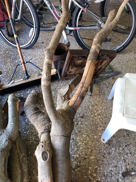
I found even nicer pieces of holly on my second visit to the brushpile, including logs of 5-6" diameter with extensive straight segments and no branching. Some are as long as 24"! And there is even more there if I want it; but I am having to restrain myself! I took a couple of pieces with painted ends, and started work on de-barking them. For this I was using my best available tool, a sub-optimal 3/4" width chisel. Now I am in the market for a draw-knife! Hopefully I will be able to get to the bandsaw later this week.
-
Great feedback. OK, my plan is to cut this recently harvested wood into logs of reasonable lengths, then put exterior latex on the ends. I will get it to my neighbor's bandsaw as soon as I can for "slabbing", as you call it Druxey. For an individual log, I will probably split it right down the middle first, then slice what is left in such a way as to exclude the pith. Then I have to find a place to sticker all this wood! For the older piece I showed you, that will go to the back burner since it is already dried over many years. As you can see, it already has long splits in it. And much of the bark is still on.
-
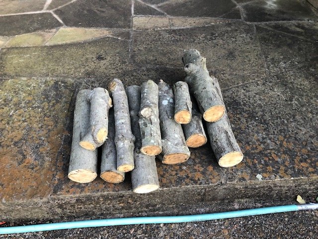
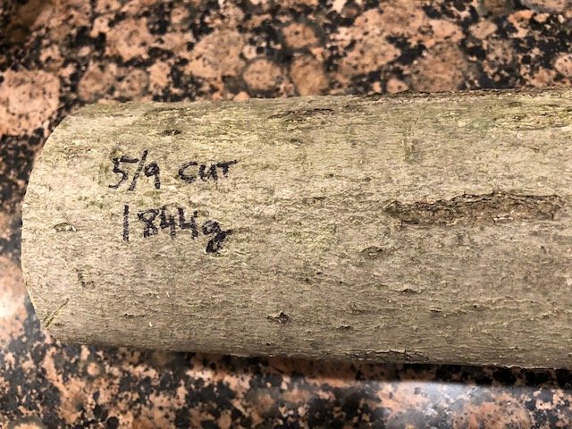
Coincidentally, I just scavenged some holly from a neighbor that is freshly cut down. These pieces have a greatest diameter of 3.5" and smallest diameter of 2". I tried to cut it so as to exclude major branch points. These segments are about 12" in length. Jaager, I guess I should paint the ends and peel the bark when possible. But are you recommending that I go ahead and rip it into sheets prior to letting it dry? For the fun of it, I labeled the straightest piece with the date and with its weight. I also have this older and fully seasoned complex piece of holly that is as great as 8" at its base. Since I now have momentum, I will probably start on cutting it up. When using holly for ship modeling, is it necessary to worry about excluding the pith at the center of the log, or is all of the wood fair game? Edward, sorry for hijacking your post but it seemed like very good timing to add to your post and not start a new one.


-
The illustrious Keith! Honored to have you following me! I enjoyed your Altair build. Hopefully I will have another post soon.
-
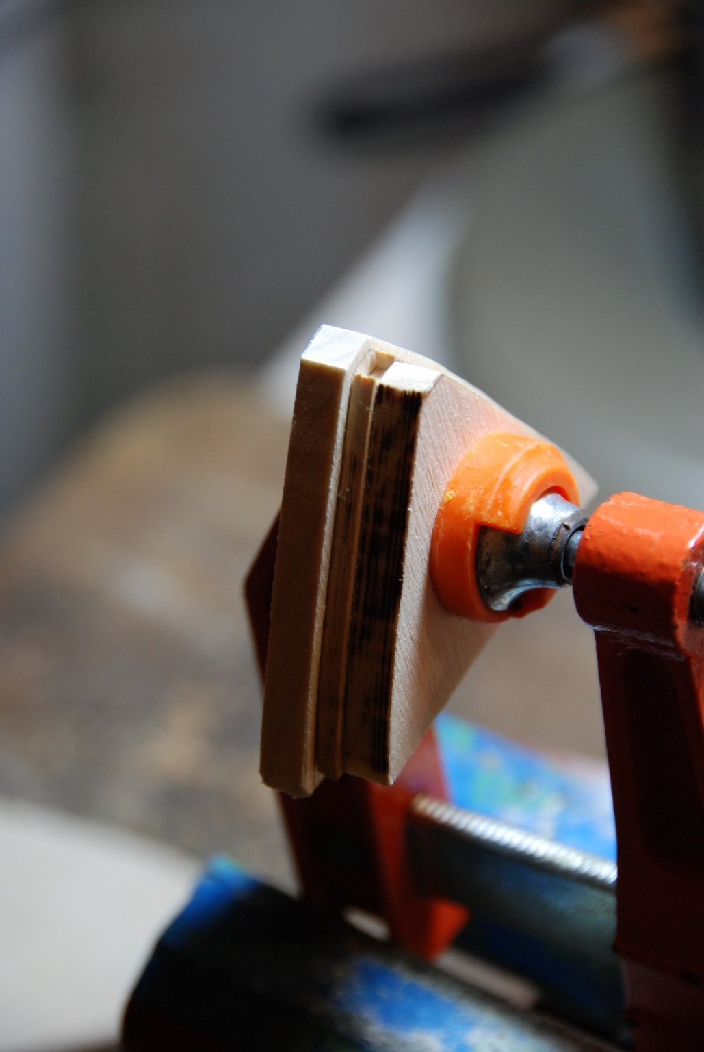
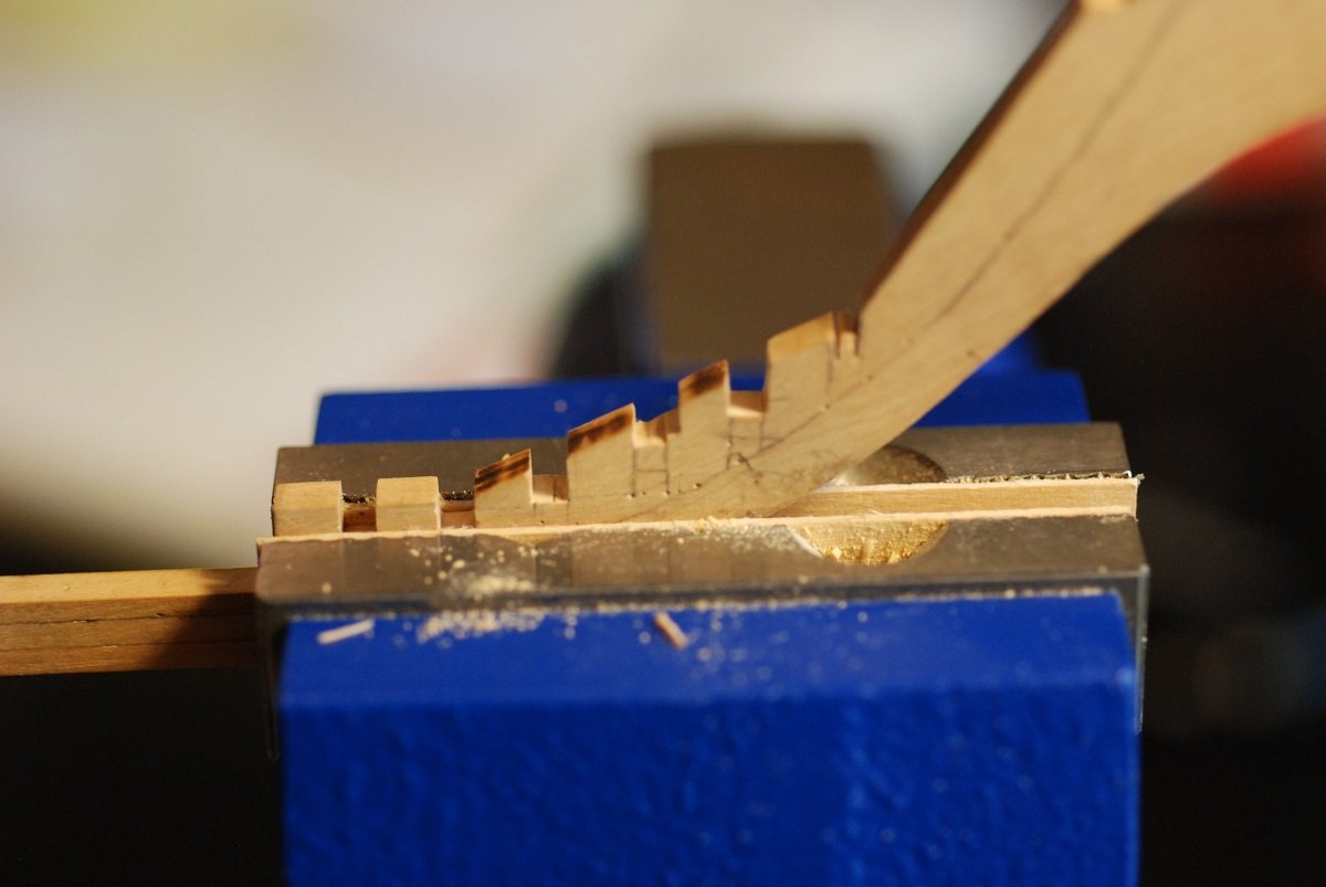
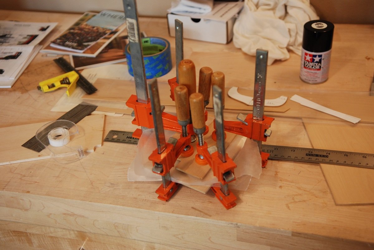
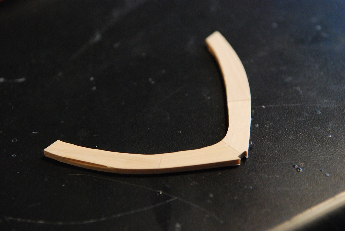
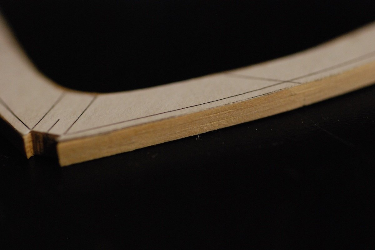
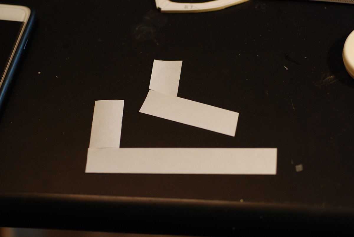
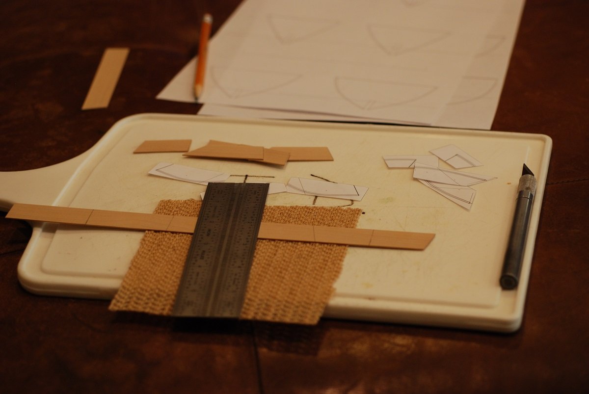
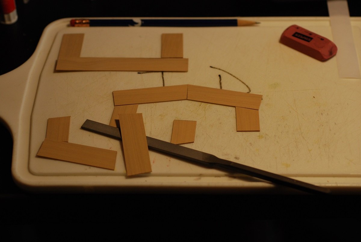
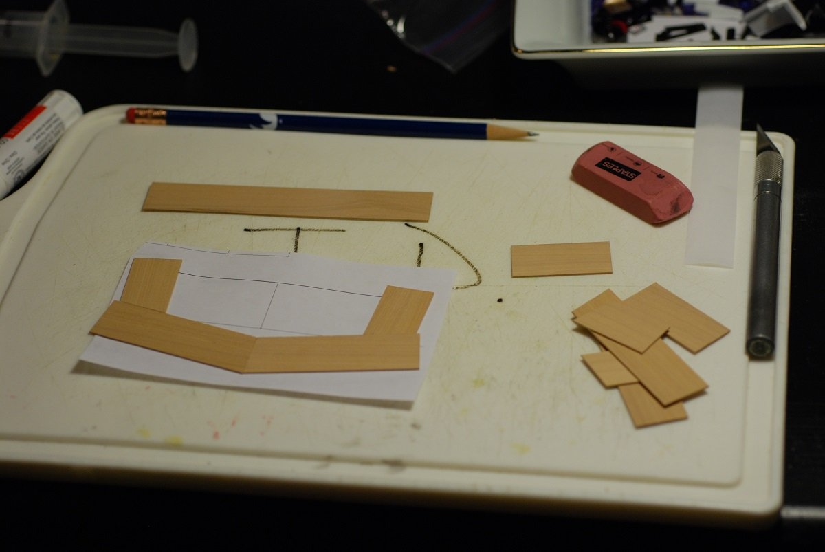
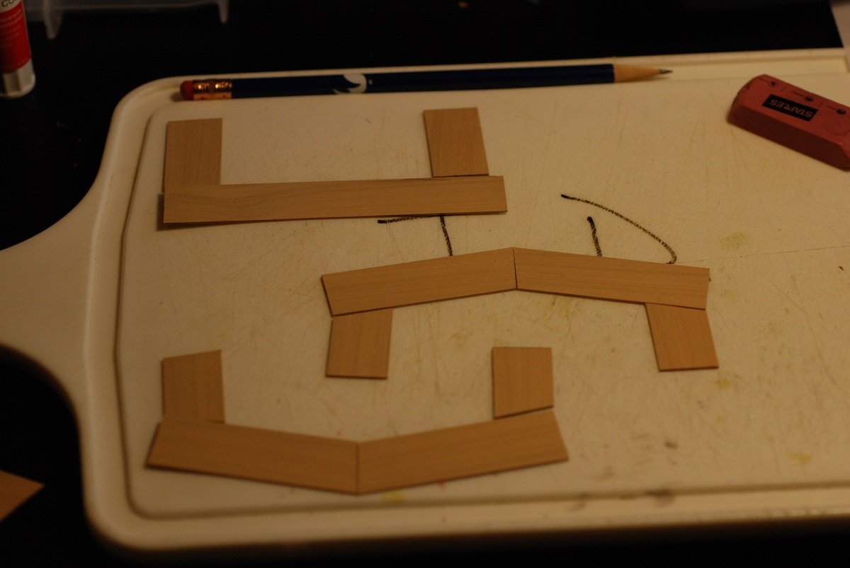
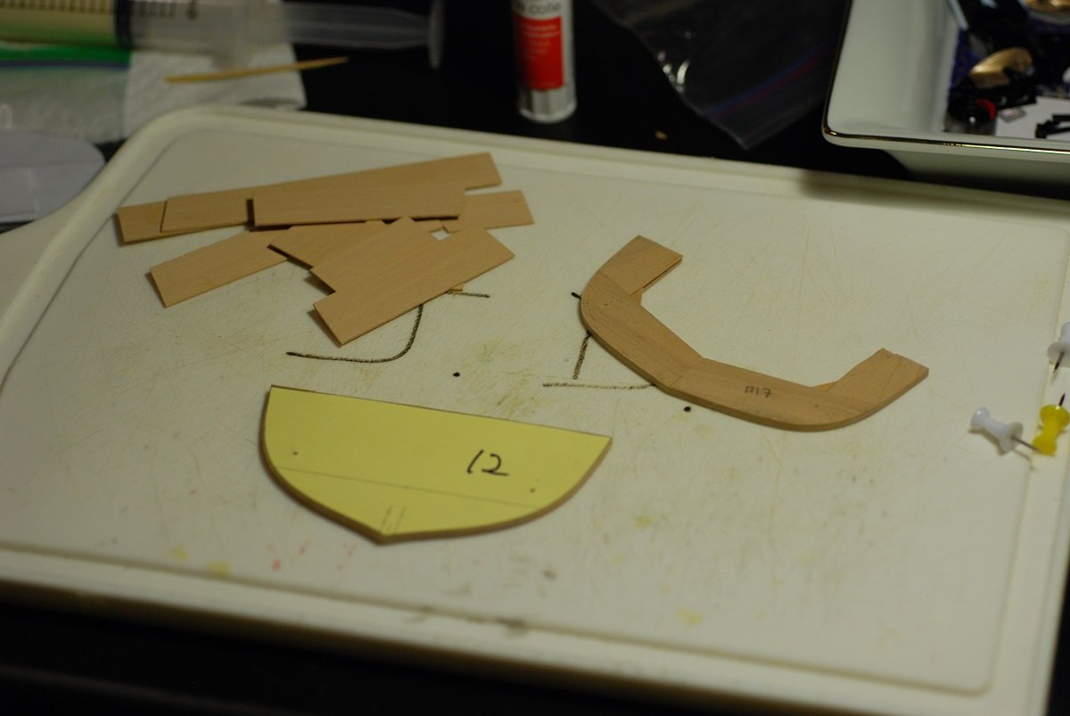
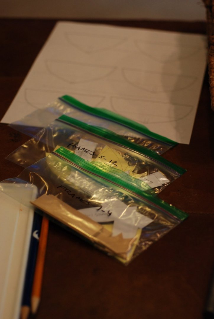
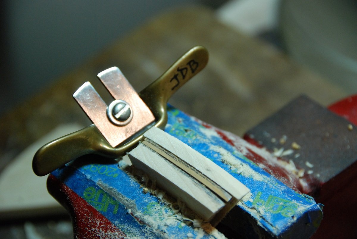
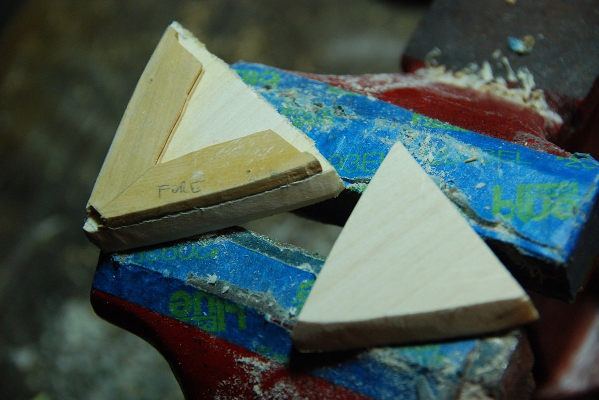
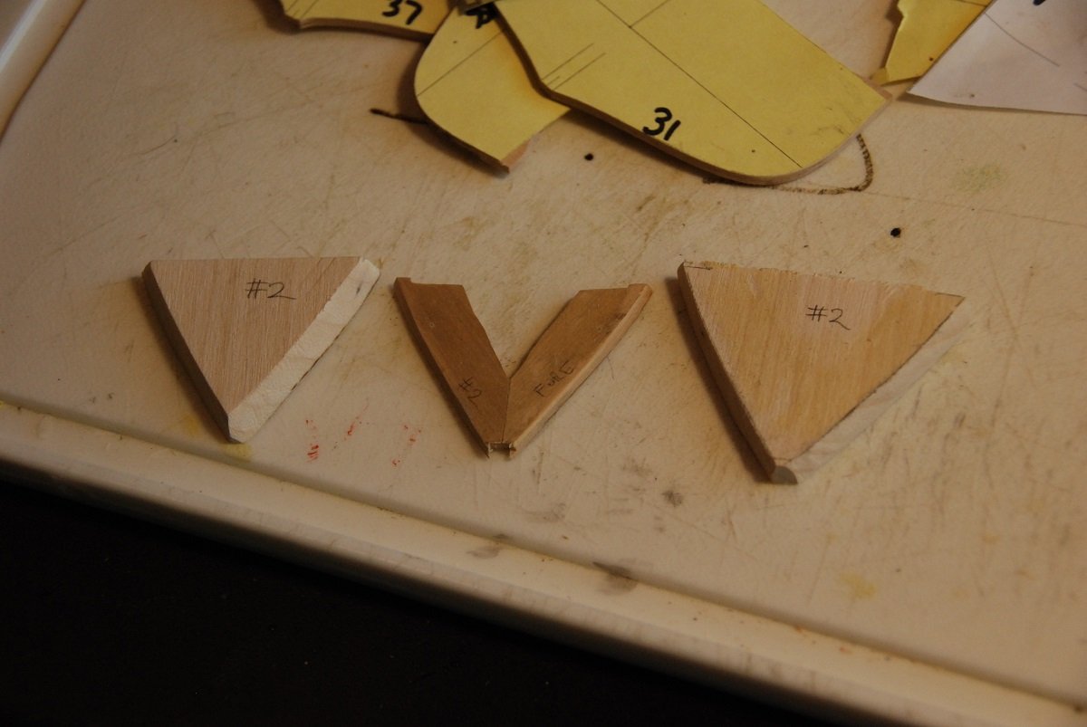
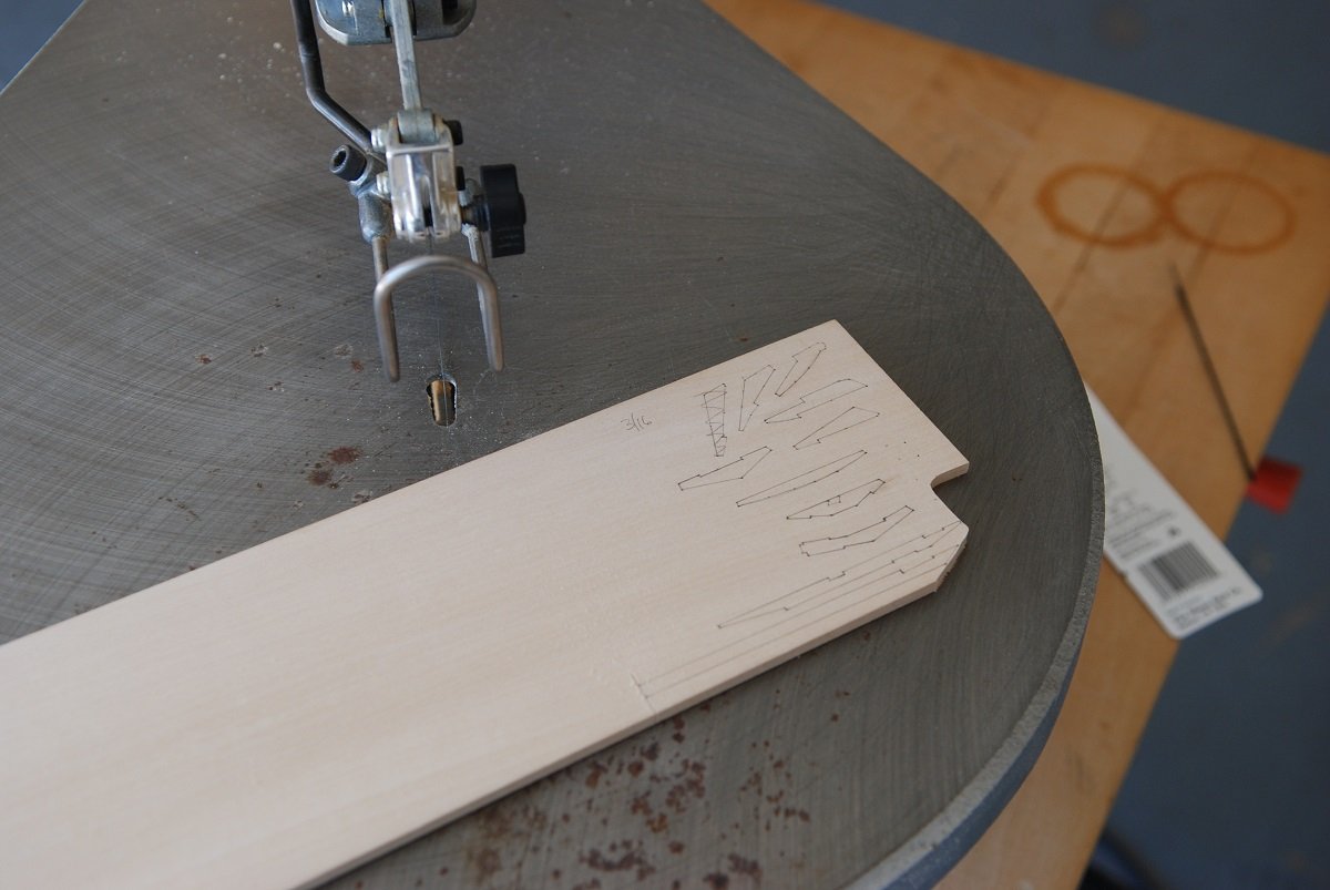
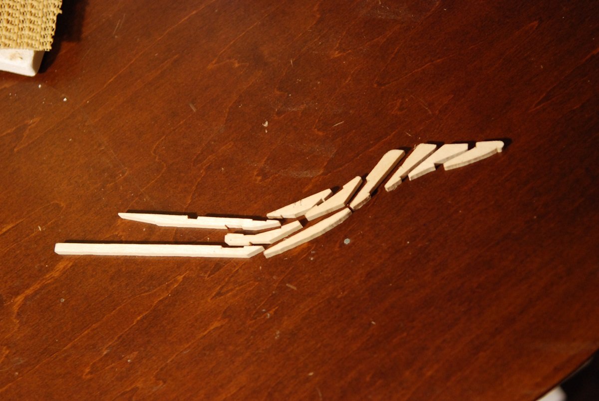
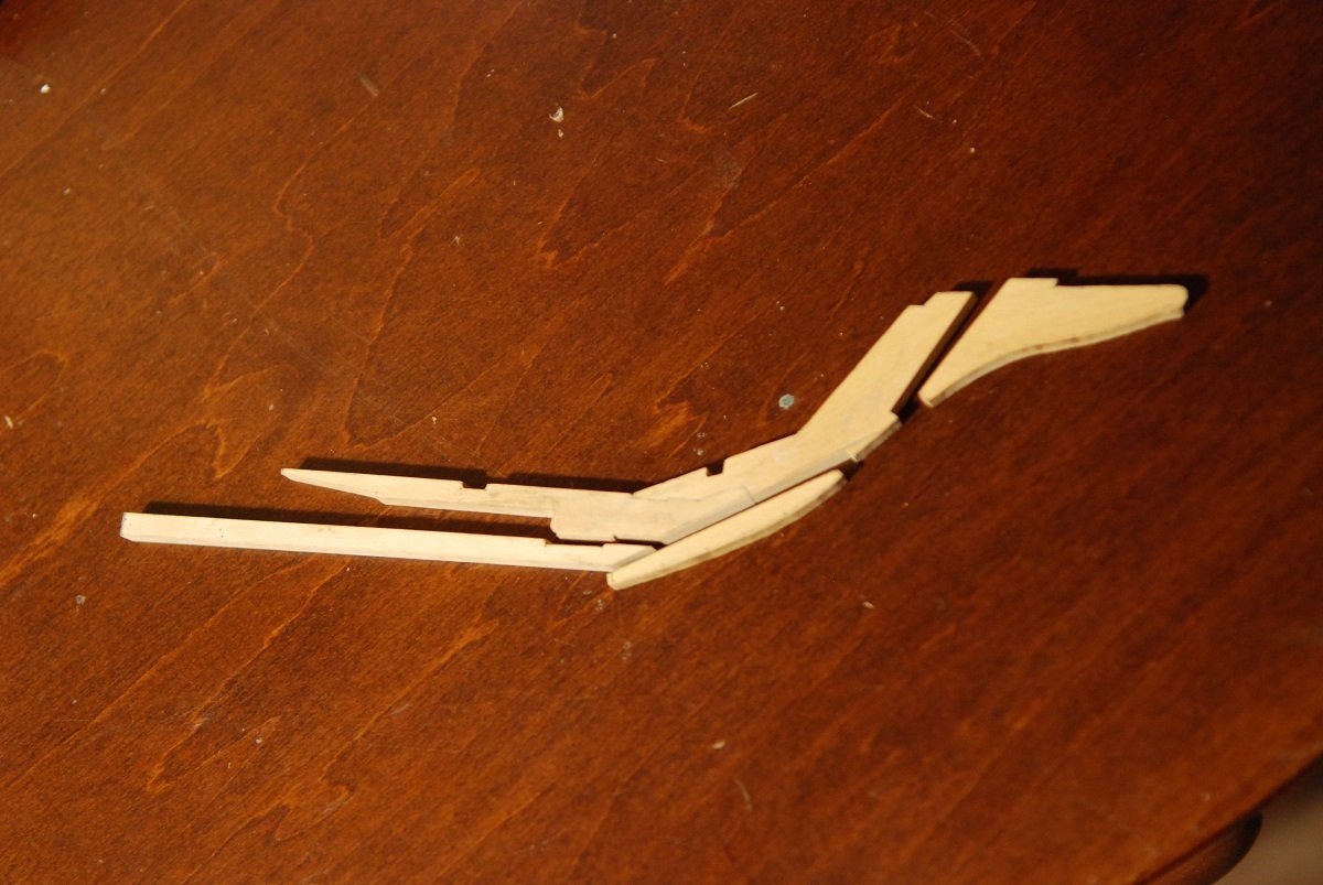
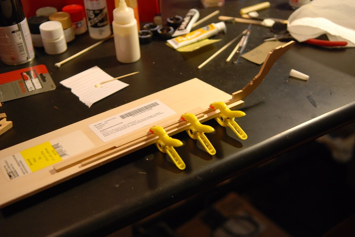
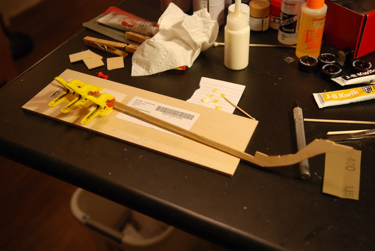
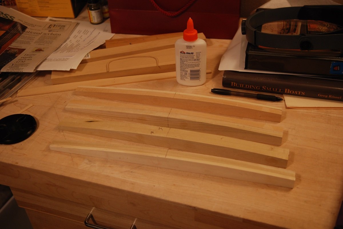
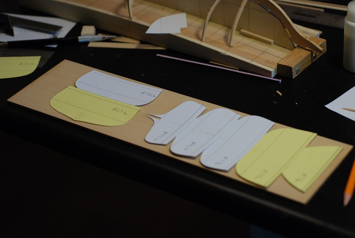
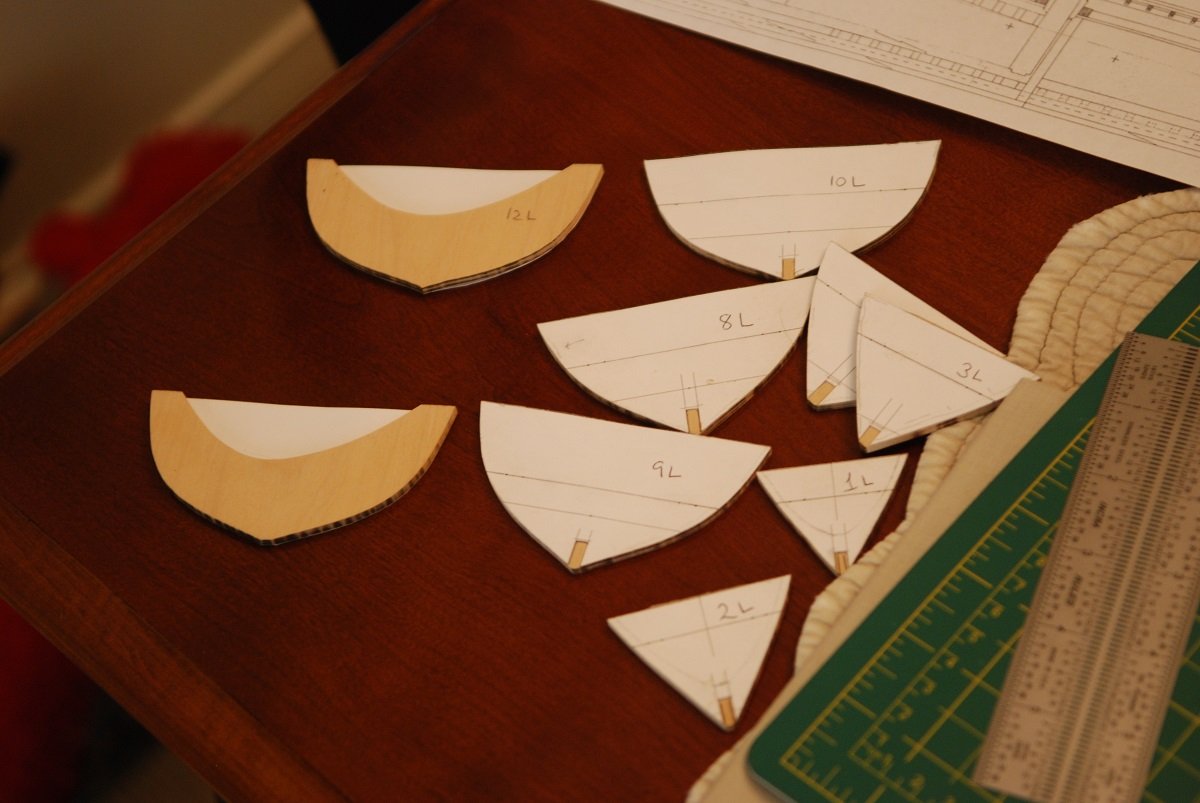
My last post consisted of work that went through October of 2018. At that point, I became involved in a craft project for a Christmas gift, so the model went on the back burner through the holidays…and MLK holiday…and Valentine’s Day…anyway, we pick back up in April 2019. I excitedly returned to the project and pulled out frames that I had cut from boxwood sheets that were 1/8” thickness, and found that the frames had warped along the narrow dimension of the wood sheets I had cut them from. I covered this topic on a post I made on MSW back in the spring of 2019 looking for guidance on how to solve this problem. If you have already seen it, my apologies. I bet that the warping would not have been as profound if the frames did not have the central part cut out of them. I imagine that a relatively triangular piece of wood with the outer edge cut to the shape of the frame would not have warped, at least as much as occurred here. There is of course the well-documented method of building up a ship’s framing by laminating thin layers of wood together. This is a test frame made of pieces of 1/32” boxwood, layered up with wood glue. Then pressed together overnight sandwiched between sheets of wood and layers of wax paper. I then cut this frame to shape using one of the printed patterns from my Rhino model, and created a keel notch. Upon close examination, you can see the 3 layers of wood. So proof of concept! As if the concept needed proving… So from here, how to go about doing this efficiently? I grouped frames so that a particular pattern could be used to craft a series of frames. These sheets of paper were used to model frames that had some degree of crossing of the grain. Using the table saw and thickness sander, multiple sheets of 1/32” boxwood were created. Here I am cutting the strips according to the paper patterns. Frames were layered up according to the patterns. These were glued up, and were pressed in a more efficient manner involving sandwiching them between wood boards, which were then pressed down using multiple heavy books and a 15 pound weight on top of the books. An example of how a particular pattern could be used for multiple frames. A scroll saw was used to cut close to the pattern, then a drum sander to bring it even closer. Hand sanding using 180 grit sandpaper was the final step. These frames were grouped into bags; some of these bags contain cut boxwood sheets prior to assembly, with their associated patterns in case more frames had to be made. I am happy to report that since these frames were created in April 2019, none have warped over the past year. The frames in the bow obviously will require extensive beveling to accept the planking. The following pictures are an attempt to pre-bevel these frames prior to installation. This frame is sandwiched between two thicker sheets of wood that are cut to the shape of the forward and after surfaces of the frame, as calculated by the Rhino program. This is a small spokeshave used to smooth the edges of the frame and the adjacent wood sheets. This is frame number 2 after beveling, removed from its wood sandwich. I did this process for the first 7 frames in the bow, but I haven’t done it for any other frames since then. This is because I envisioned fairing the frames once they were placed on the baseboard, with wood sheet inserts between the frames to stabilize them while a sanding board is used to do the beveling. Back to the baseboard and keel in the next post!

-
That's a big help, Toni. Eventually I will be confronted with the same issue on my current build.
-
I have another deck planking "rules" question. How were the nibs of the planks laid out in the bow and stern? Are those specifically delineated in your plans, or are there once again "rules" as to when to end an edge plank and nib it into the adjacent plank? I can see that the adjacent inboard plank would have to be narrowed as you approach the nib, in order to end up with a full width plank at and beyond the nib.
-
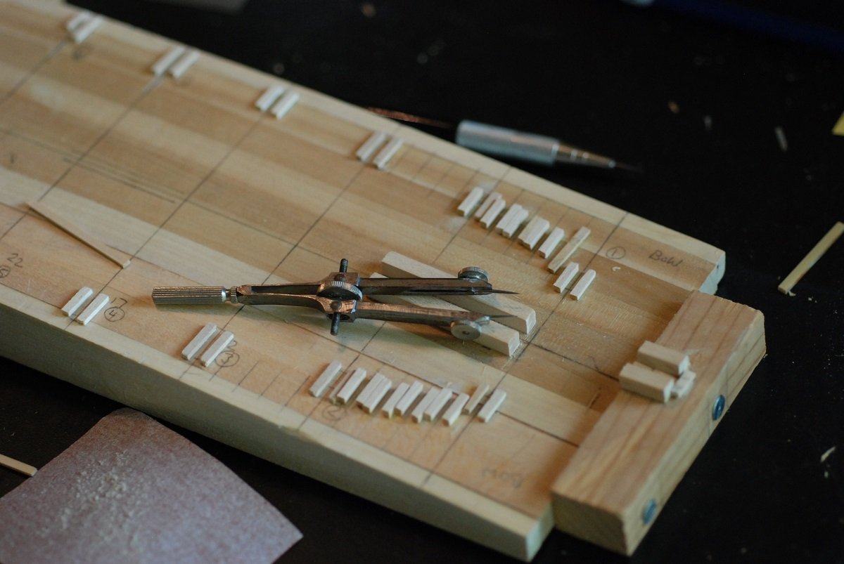
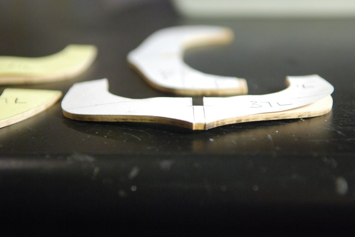
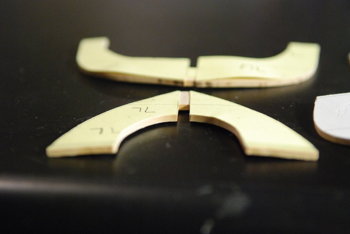
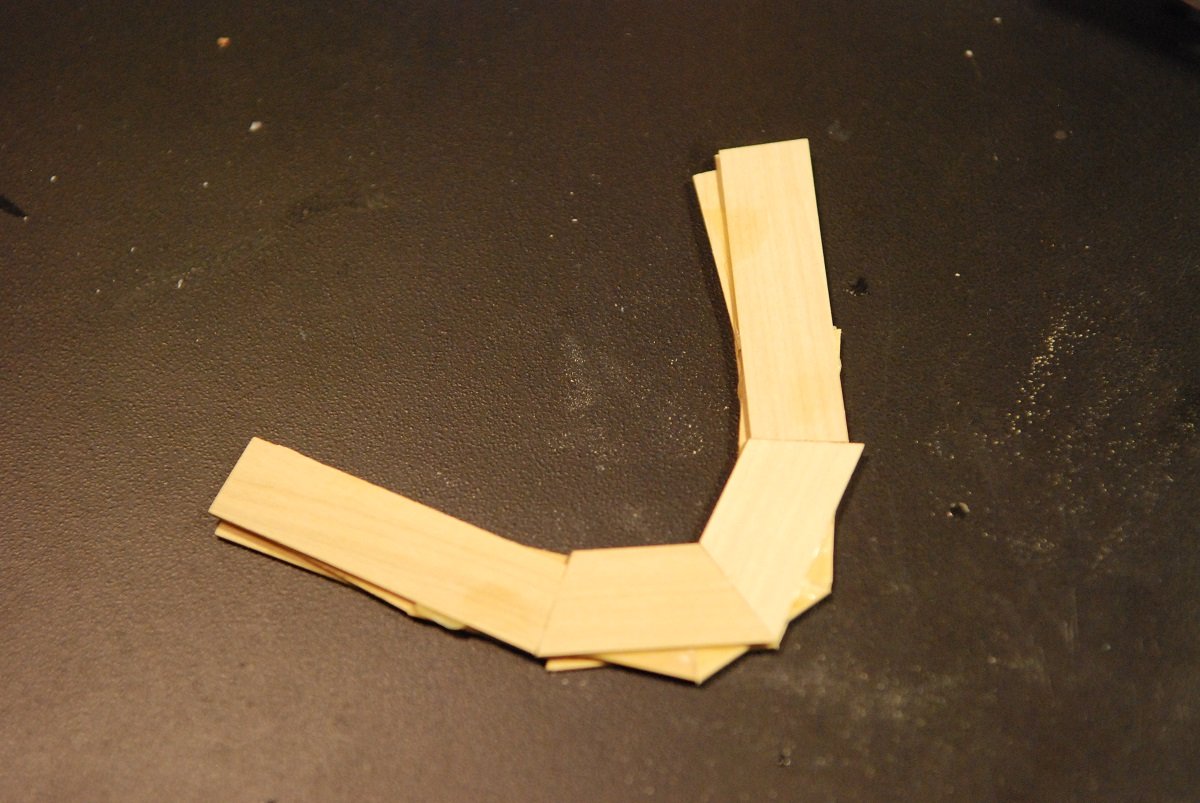
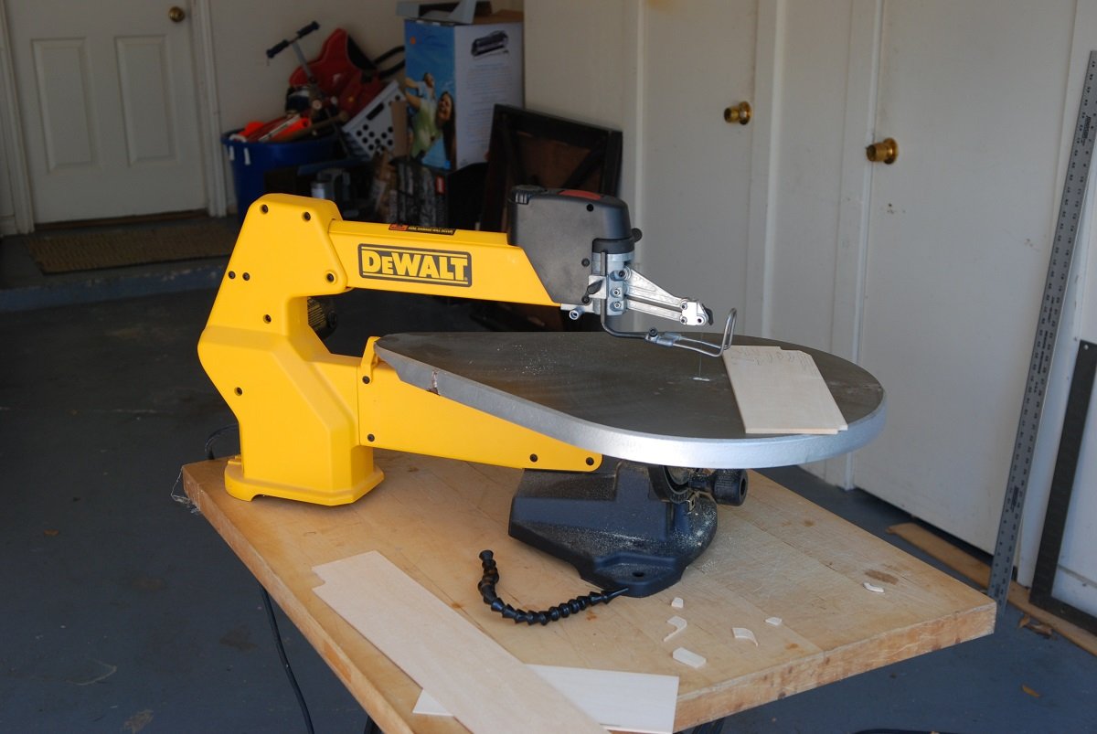
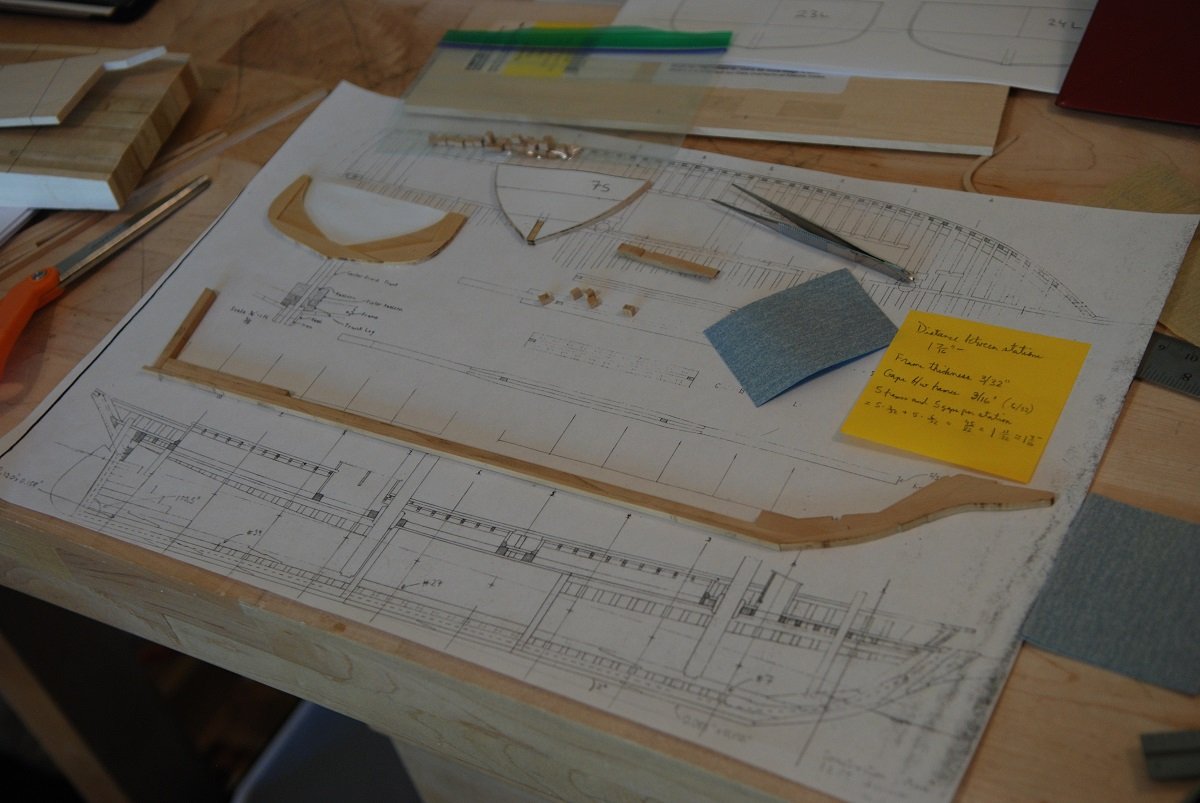
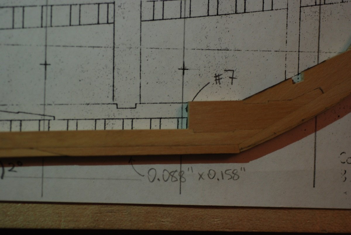
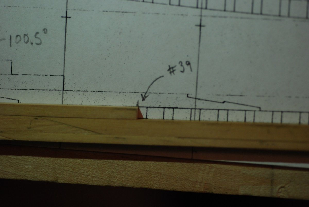
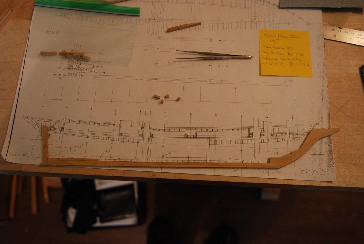
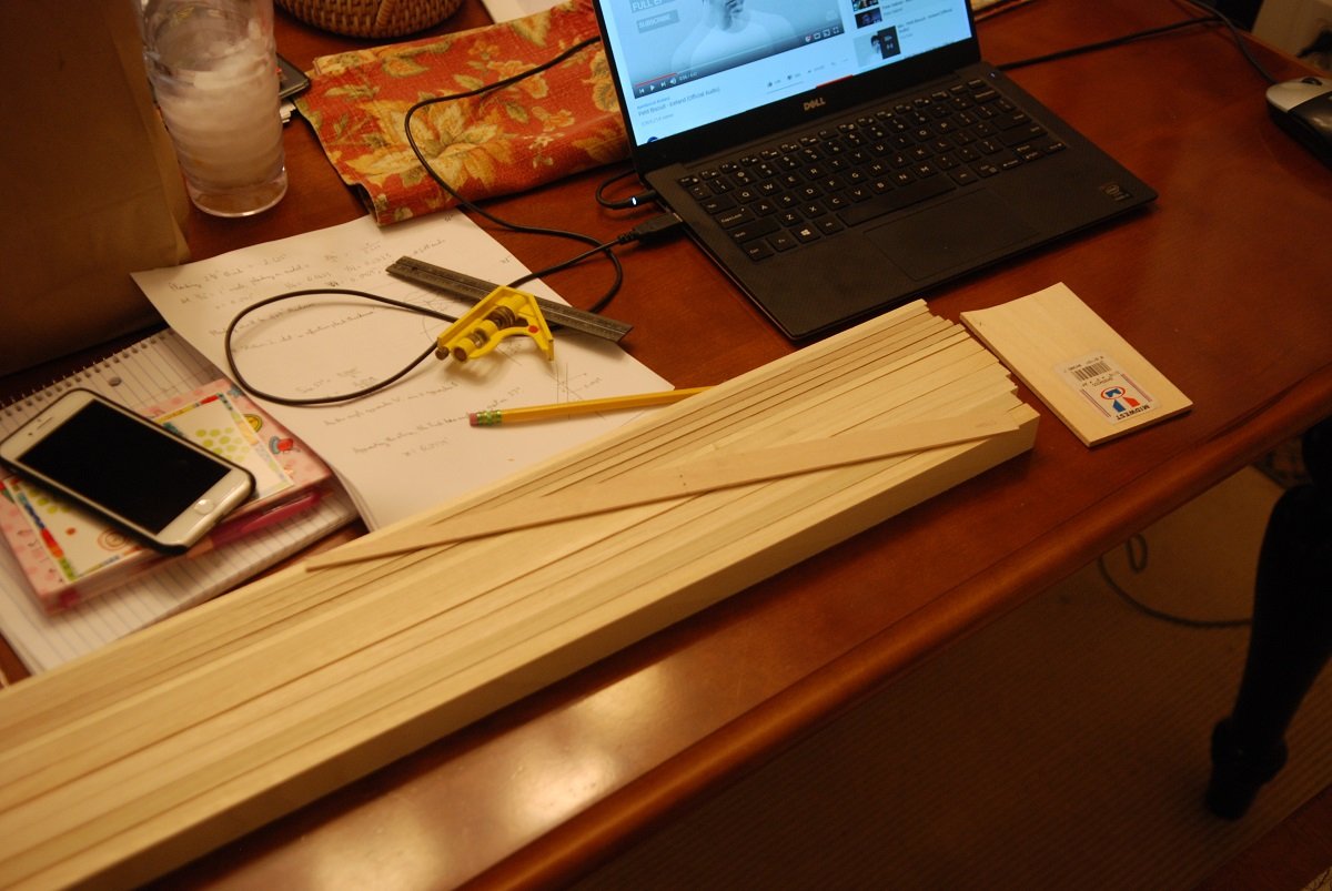
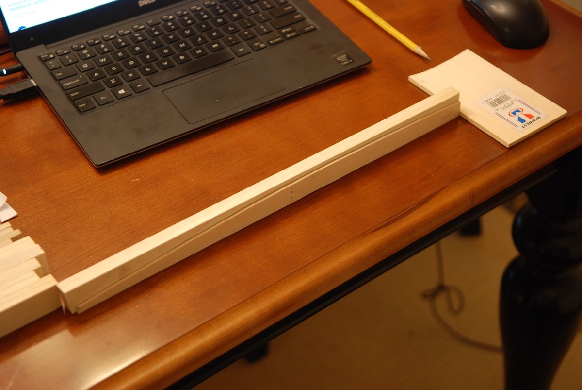
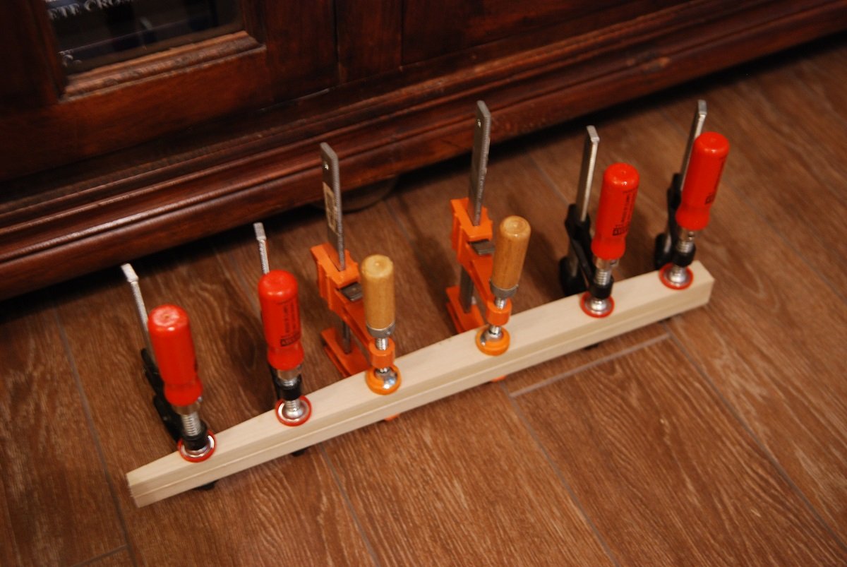
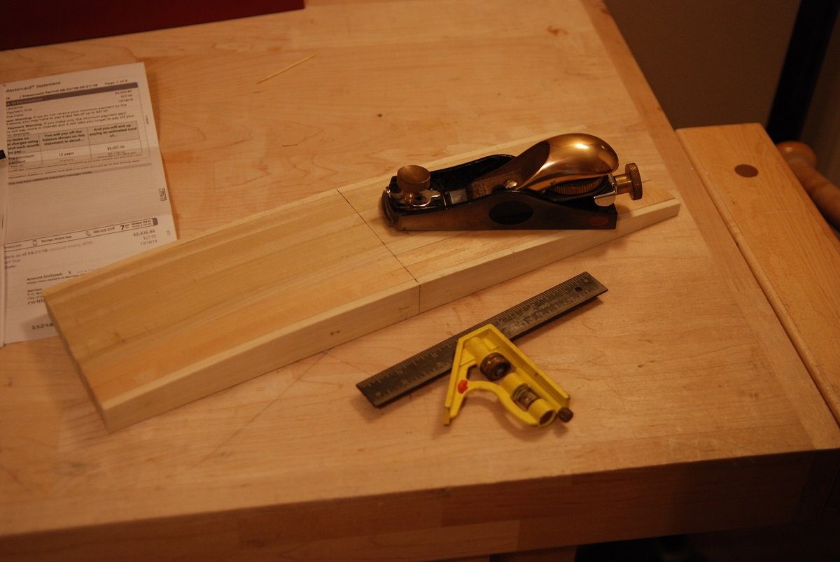
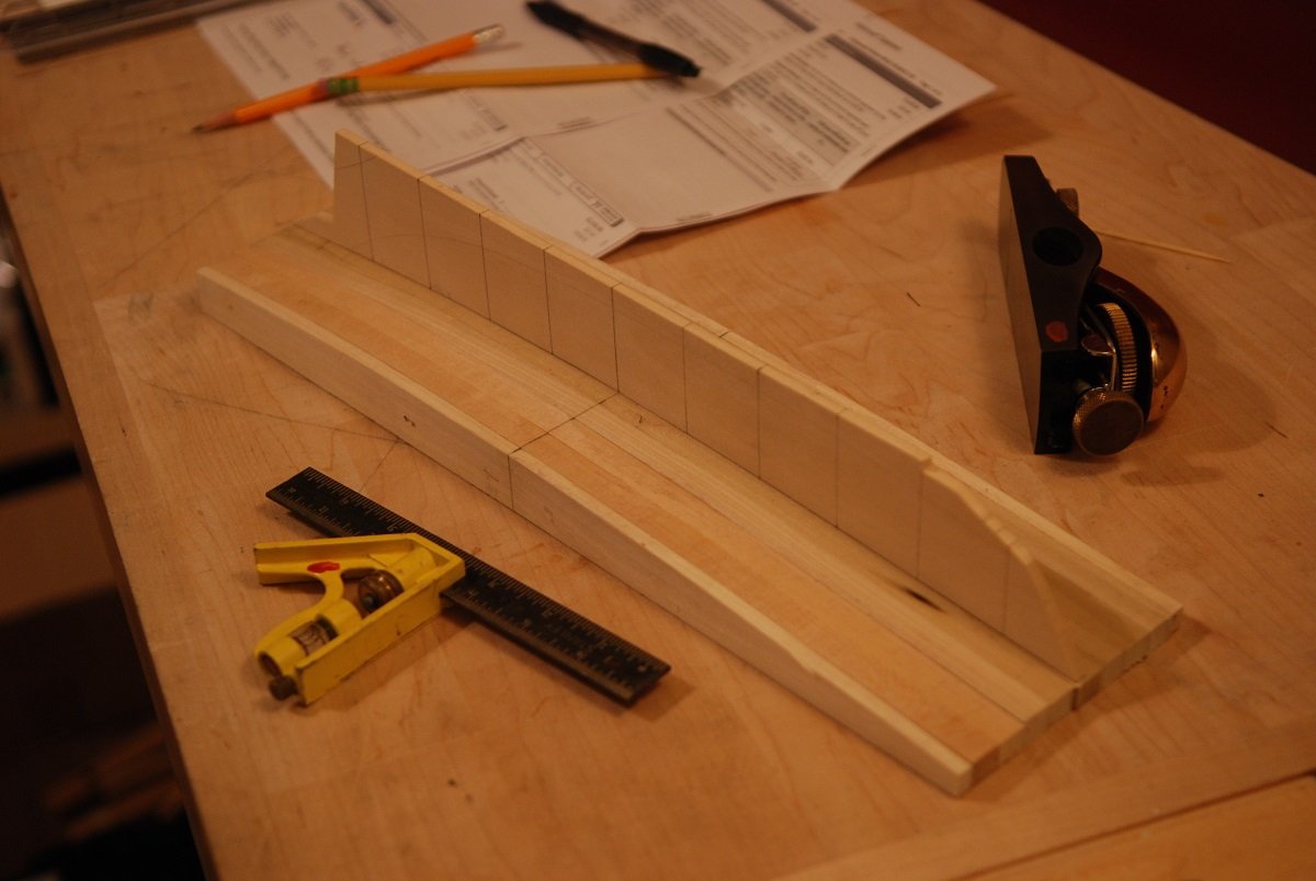
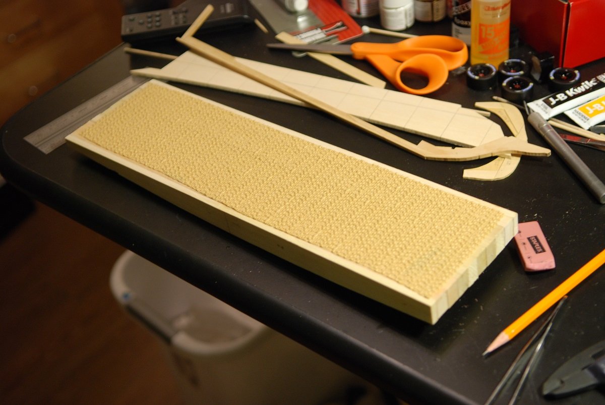
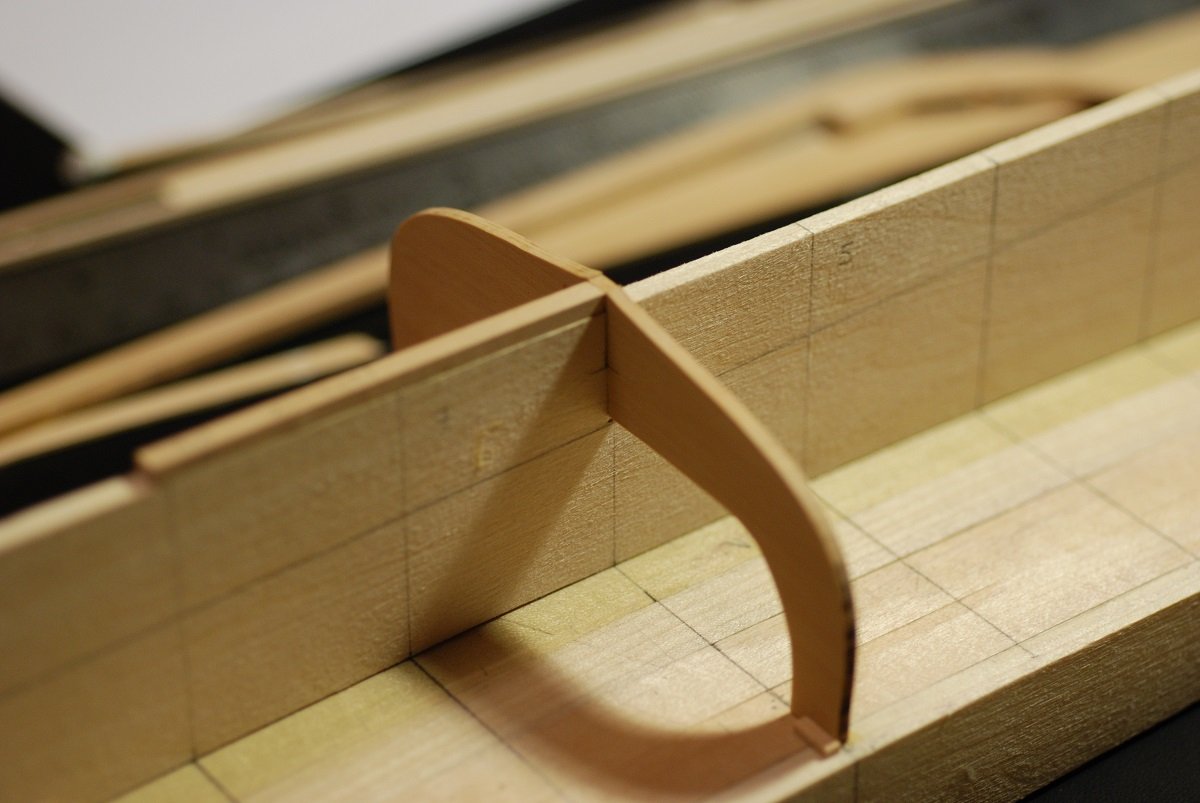
As mentioned in the last post, the keel construction was done by creating a copy of the builder’s plan on to transparency. Pinpricks were used to mark the dimensions of the multiple pieces that constitute the stem. These were initially transferred on to basswood of 3/16” thickness. The scroll saw is the weapon of choice for cutting the individual pieces out. They were cut as close to the line as I dared, then finished with files. Following the builder’s plan to the letter, the stem is built of eight different pieces. However, I learned 2 things from this: 1. Basswood is too fuzzy to allow for accurate joint formation between individual pieces. 2. Making the keel out of so many different pieces created a final product that did not fit the overall shape of the keel on the builder’s plan. At this point, I reverted to 3/16” thickness boxwood, and built many of the parts together so that the stem was made of only 3 parts, which fitted together very accurately. Once these were joined together, the assembly was thickness sanded to correspond to the thickness on the builder’s drawing, approximately 0.158”, or about 5/32”. This represents 10 inches in width at full scale. This jig was created to ensure accurate joining of the segments making up the long, straight keel. The segments are joined by scarf joints that were carefully created by a very small hand plane. A second joint further aft. The sternpost and a piece of deadwood have been added. The keel was carefully checked against the builder’s plan to make sure that the spacing of the slots for the frames was correct at the stem… …and near the stern at the start of the deadwood. Got a good shape to the keel overall. The small pieces in the center of the picture will be used to create the keel notches for the frames. All of this was possible without needing the help of Rhino 3D. The same is true for the base upon which the model will be built. It will be built upside-down, with the surface of the base in the shape of the curve of the sheerline. Specifically, the sheerline at the level of the top of the bulwarks (which would be the same as the undersurface of the caprail). These are basswood sheets that will each be cut to the shape of the sheerline, then glued against one another. Sheerline is cut into the first of the basswood sheets. Then two of them are glued together. 8 sheets become 4, then 4 become one. The surface was smoothed with a low angle block plane, with the carpenter’s square ensuring a smooth and even surface. This anti-skid material was glued to the undersurface of the base. This insert was created to support the keel. I initially thought I would slot frames into this insert as well as the keel. So the idea was that I could notch each frame, and notch the insert, so the frame and keel could be brought together reliably. Shims are visible on the base that locate the upper part of the frame. Multiple frames have now been put in, with shims adjacent to the top edges of the frames to stabilize their position. The frames were cut from 1/8” boxwood sheets, and using the thickness planer were thinned to 3/32”. The edges were cleaned up using a shaper table with a ½” sanding drum, then hand sanded to the shape of the paper templates. So far, so good…we’ll see what happens next…
-
Ha ha Michael, I wish I was that good with Rhino! Of course if I was, I would be doing something else for a living... Druxey, it was an incredible feeling having those plans put in my hands. I couldn't believe it. The builder's plan in fact was a blueprint, essentially an original! Skipper Barry King said, "You know, I've been thinking I need to give a copy of these to someone for long term storage." I said, "how about that museum back up the road?" (The Penobscot Marine Museum is where I had gone searching for the plans in the first place!)
-
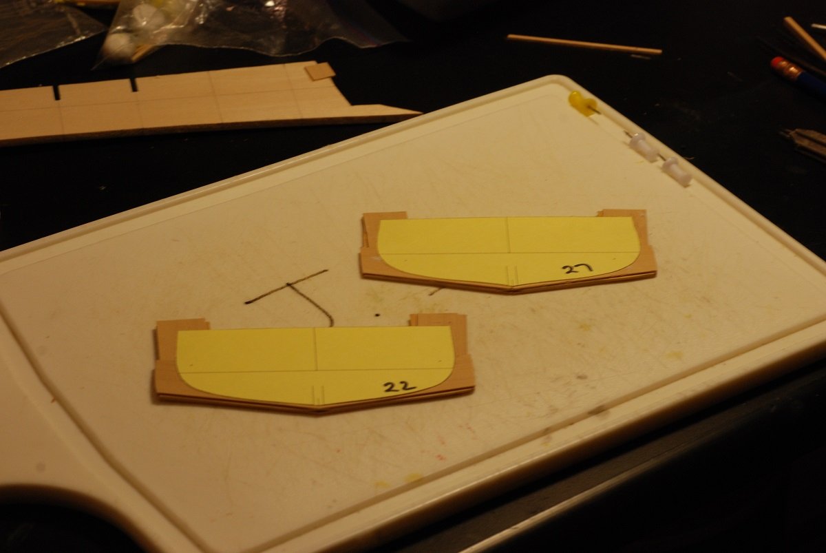
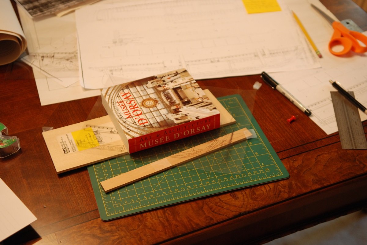
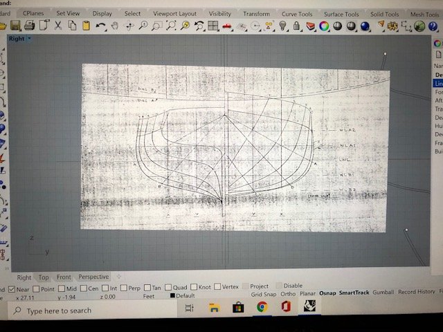
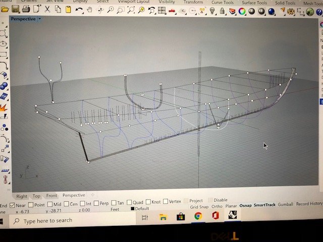
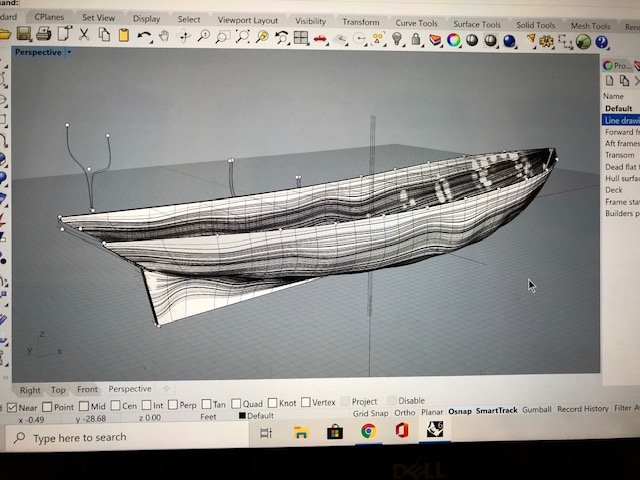
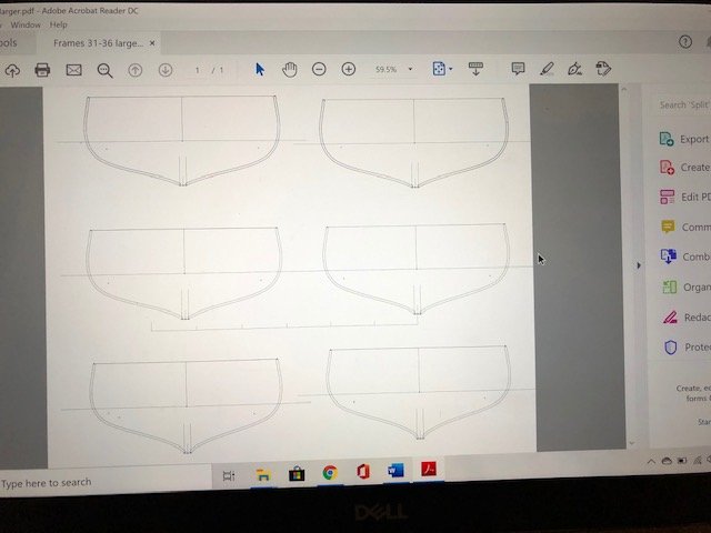
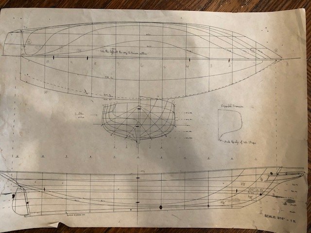
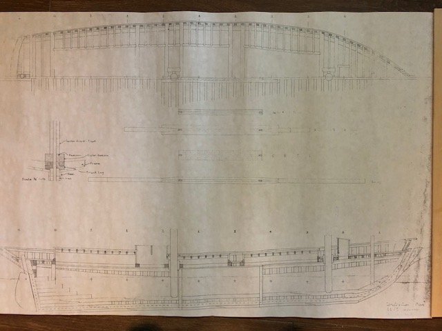
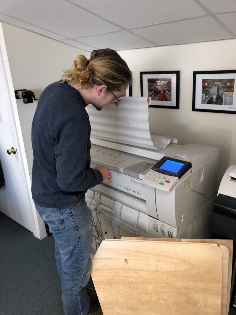
The first order of business was to figure out how to make use of these wonderful builders plans I got from the crew of the Mary Day. The plans consisted of 3/8” scale builder’s plan showing the structure of the keel, the frame locations, the structure of the deck, and location of the cabinhouses on the profile view; then there was also a 3/8” scale lines drawing of the hull that was essentially the same as the old 3/16” scale lines drawing I had received from them shortly after our cruise. These very large plans (24x36”) were scanned by the staff at Brooklin Boat Yard, creating very large image files. Once I got back home, I had the scanned files reprinted at the original 3/8” scale, and I had multiple copies made of the plans at 3/16” for use in the shop. I had previously played with Rhino 3D many years earlier, back when I was doing some research involving CT scans of historic ship models. All that had been done using a trial version of Rhino, but it was time to make the investment. So I plunked down the four-figure amount of money for a full version of Rhino 3D. I could have gone cheaper, but I figured it was better to build on what I already knew about Rhino rather than have to start anew with some other program. It took some doing to remember how to take an image such as the builder’s plans and make it appear as an image in Rhino so that tracings could be taken. Help was found in the form of at least one article in the Nautical Research Journal that refreshed my memory on the necessary commands. The builder’s plan was thus imported, and it had to be carefully leveled to make sure everything was square. A long line was drawn through the waterline, and this was used as a handle to grab the plans and make very small incremental rotations in the plans. I could go into a lot of detail about the steps involved in generating a 3D model of the ship, but the condensed version is that after inputting all the possible information from the builder’s plan, the lines drawing was used to take the shapes of the molds at eleven stations. These shapes were then moved to their appropriate station fore and aft on the profile view. In addition, the shape of the keel had to be created, and there was a lot of detail work involving the shape of the bow and the transom. But once all this information was present, Rhino was able to render the surface of the hull and give me the shape of the hull from the tops of the bulwark stanchions to the bottom of the keel. I could then take a cross-section of the hull’s shape at any point along the fore-and-aft length of the vessel. Using a surface offset function, the thickness of the hull planking could be deducted, giving the needed shape for the frames upon which the planking would rest. Frame patterns were created in this way for each of 51 (!) frames along the length of the hull. The image above is a pdf output from Rhino, and for each station it shows the shape of the station, outlined by a pair of lines that indicate the thickness of the planking. The width of the keel is indicated by the parallel lines at the bottom of each station, and the waterline is also drawn in. These frames were printed on cardstock, carefully cut out, and numbered. This process required about 7 months to work through. Fortunately, while I slogged through this process, it was also possible to actually work on building the keel shape using the 3/16” scale builder’s plans. These were copied on to transparency, and pinpricks through the transparency were used to transfer the patterns to wood. I will go there in the next post.

-
Thanks for all the likes and followers!
-
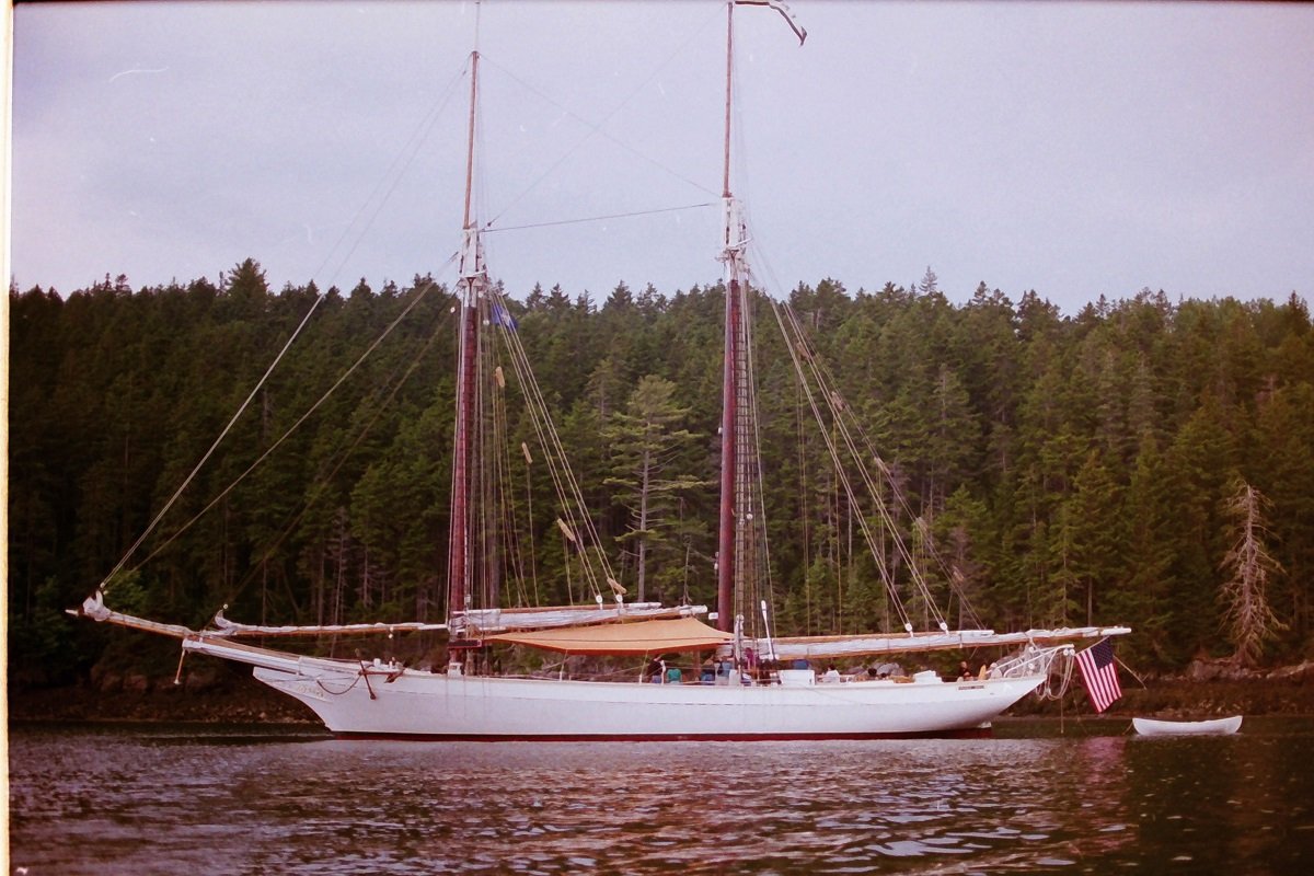
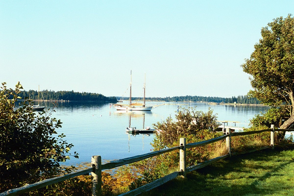
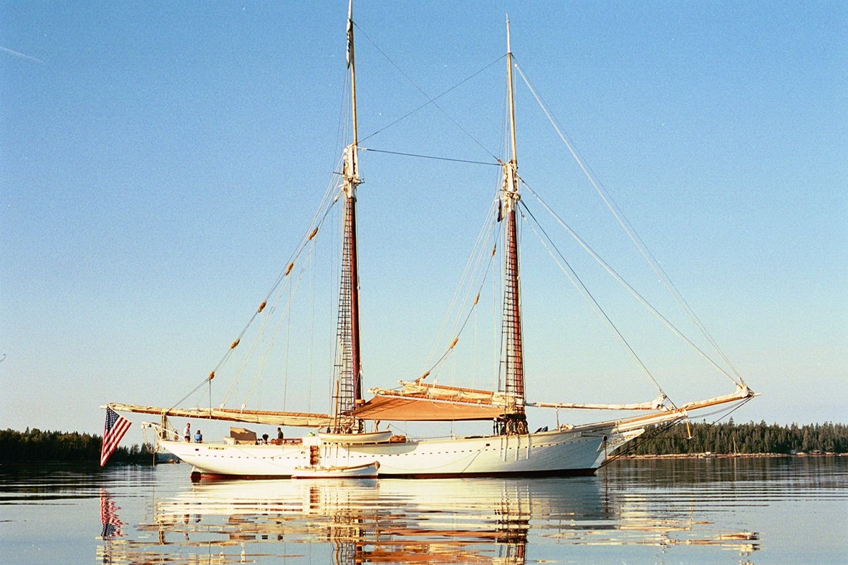
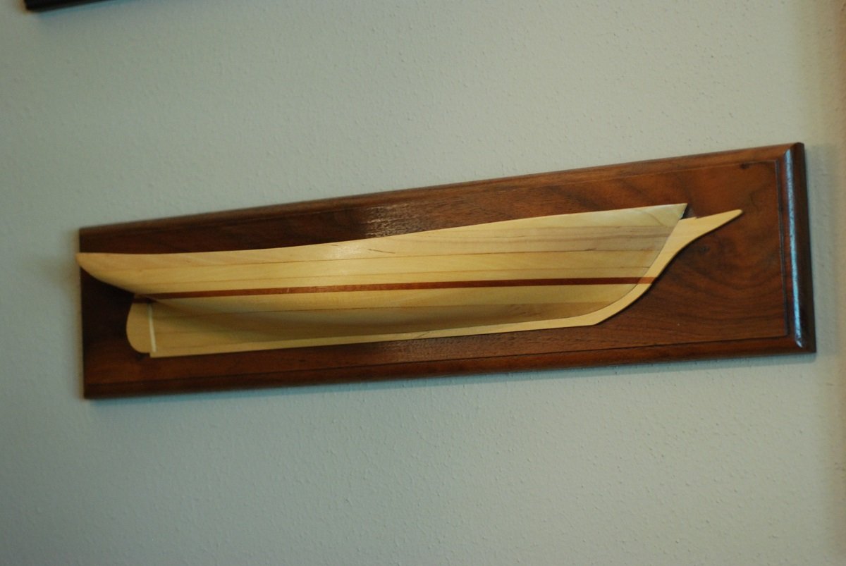
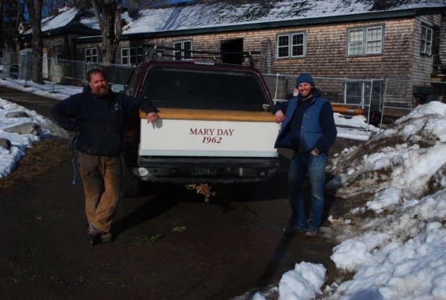
The schooner Mary Day is a passenger schooner on the coast of Maine that is based out of Camden. She was built at the Harvey Gamage shipyard that was located in South Bristol, Maine, and launched in 1962. Her designer was Arno Day, and she is named for his daughter. The Mary Day was designed and constructed to be a passenger schooner, and therefore has not been converted from any previous use. It was Havilah Hawkins that conceived of the idea of a schooner built specifically for the passenger trade. You can learn more about her at schoonermaryday.com, and I encourage everyone to visit their webpage. She is such an important part of coastal Maine’s heritage. My wife and I took a cruise on the Mary Day in 1997, as a sort of delayed honeymoon since we got married when I was still in medical training (in 1994). Barry King was the captain of that cruise, and shortly thereafter he and his wife Jennifer Martin took over ownership of the boat. It was during this same time frame that my interest in model boat building was developing, and I always kept in the back of my mind the idea of building a model of her, even though my skills at that time would only permit the idea of building model boats from kits. Before evolving to my current skill level, though, I did learn how to build half hull models by taking a course with Eric Dow at the Wooden Boat School in 2004. In the course of a week, each student built two models. The first was one based on purchased lines drawings from the Wooden Boat Store to build one of a variety of models, plus we could do a second model of our choosing. Shortly after our trip on the Mary Day, Barry and Jen had kindly sent me the lines drawing for her: Only now do I regret using this plan sheet to directly transfer the lines to the pieces of wood used to build up her hull. I should have had accurate copies of this original made, then used those to actually build the two models I ended up creating. As a result, this original is quite beat-up after about 20 years of existence! While I was at the school, we had a surprise visit from the Mary Day, which I had not seen since our cruise 7 years earlier. To my surprise, when I reintroduced myself to Cap’n Barry, he remembered me and spontaneously asked how my wife Susan was doing! What a memory. I got this lovely picture of her as I was being rowed out to meet her. This is the product of that school week, and it hangs on the wall in my shop. I built a second model a few years later as a gift to Barry and Jen, and it resides at their business office. The lifts are made of basswood and mahogany, and the backboard is also mahogany. Before I could consider building a fully rigged model of the Mary Day, I would need more information than just a lines drawing. Over the next few years, I stayed in touch with Barry and Jen and would intermittently inquire about more complete plans for the Mary Day. There was certainly no hurry, as I was finishing a kit model that ended up taking about 20 years to build. Harvey Gamage’s shipbuilding yard had since closed, and when I checked with its successor (now known as Gamage Shipyard) about possible builders plans, they suggested that nothing would remain from their predecessor. Research at the local libraries in the area of Camden did not yield any information. In February 2018 I spent a week in Southwest Harbor, Maine, and I let Barry and Jen that I would be paying a visit to Camden. When I arrived, the first thing Barry did was to present me with full builders plans, in 3/8” scale! A dream come true. The most important sheet looks like so: More than enough detail to build out a very accurate hull. I could even choose to model it as it really exists, with a fit-out interior including deckbeams, carlins, mast partners, and centerboard trunk. Without these plans, no model could be generated, so I am greatly indebted to the staff of the Mary Day for their help. Cap’n Barry and first mate Tony in February 2018. Having learned a lesson from the previous lines drawing they had sent me, I promptly had these plans scanned to electronic format, thanks to the good people at Brooklin Boat Yard, where I visited the next day. Having the plans in digital format would of course be very important for constructing a 3D model of the boat using Rhino 3D. I am not (yet?) the kind of model builder that is interested in researching a no-longer-in-existence vessel; I doubt I would have the patience to do the research necessary to resurrect a bygone vessel into an accurate model. My last project was of a currently existing vessel (Pride of Baltimore 2), and having direct access to the vessel was extremely important. So this project greatly appeals to me on multiple levels, not just the personal connection via our previous travels on the Mary Day, but also the physical connection of being able to return to her in Camden, Maine, and obtain any needed documentation. So buckle up! Here we go. First order of business will be to generate a 3D model, because that will enable me to determine the shape of the schooner’s frames at any point along the hull.
-
Michael, I have been delinquent in following your build. Great work! When you made the homemade scraper, what kind of incredibly small file were you using to cut the desired shape into the scraper?
- 221 replies
-
- 2
-
-
- queen anne barge
- Syren Ship Model Company
- (and 1 more)