
ERS Rich
-
Posts
761 -
Joined
-
Last visited
Content Type
Profiles
Forums
Gallery
Events
Everything posted by ERS Rich
-
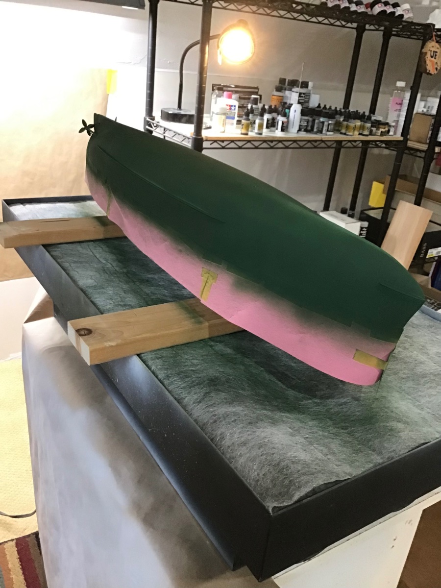
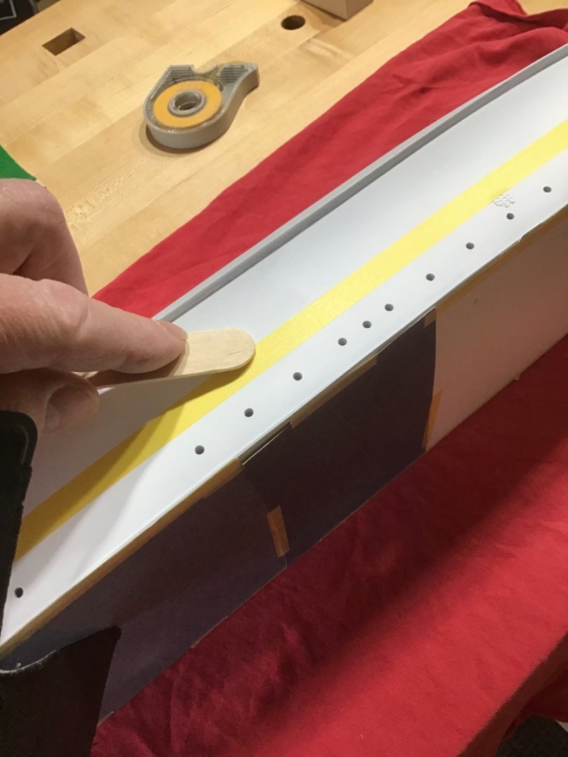
 Hull Painting - Dark Green Leveled the model and marked the waterline. Set the model on its side on a red rag, and applied a single continuous piece of Tamiya masking tape along the marks. Then lightly burnished the tape with a wooden tongue depressor. Finally used construction paper to make a skirt around the model. Applied Tamiya XF-26 Deep Green with the Iwata RG-3 mini sprayer @20#.
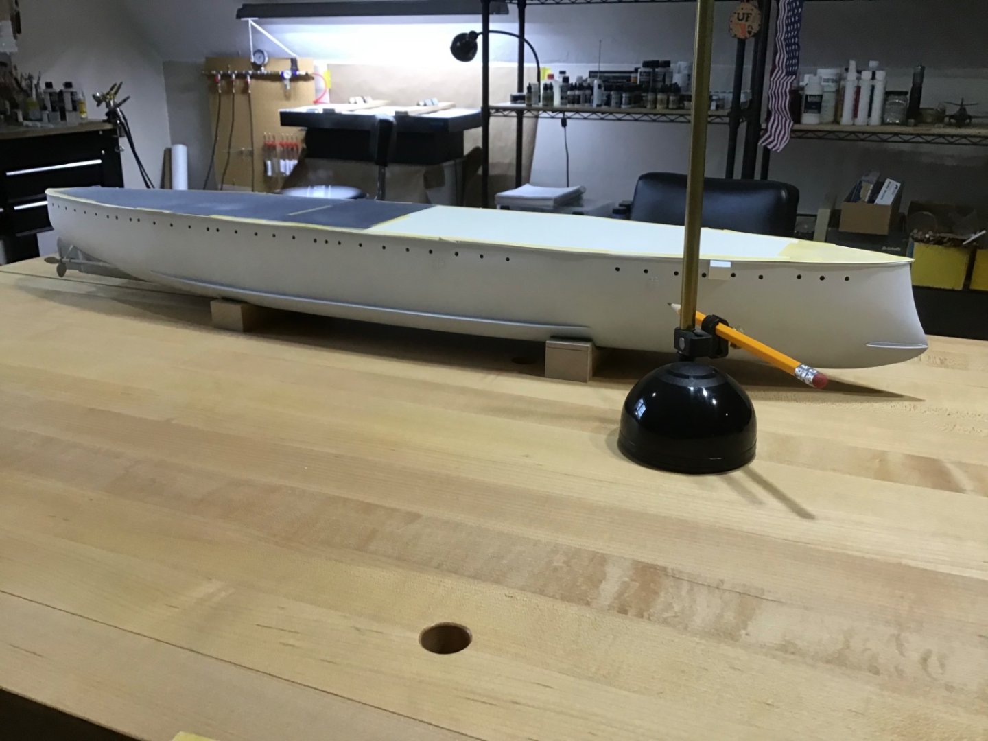

- 166 replies
-
- 7
-

-
- Maine
- BlueJacket Shipcrafters
- (and 1 more)
-
Welcome! Greetings from Massachusetts, USA.
-
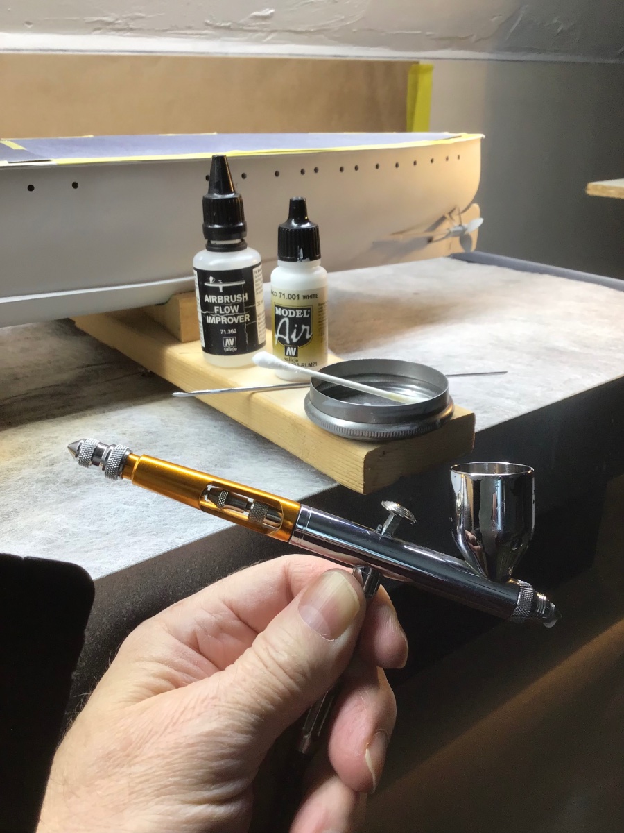
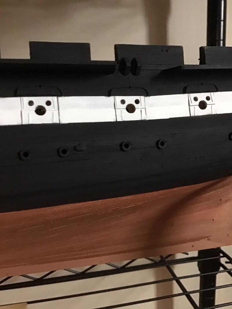
Hull Painting - White The plan is to paint the hull above the waterline white, and below the waterline dark green; so white first, mark and mask the waterline, then the dark. Considered Tamiya XF-2 Flat White, decided on Vallejo Air 71.001 White, seemed less intense to me. Dusted the hull on the table, fans on, with a soft brush. The setup is Paasche Talon, #3 tip, @22#. Paint applied in coats. Each coat is 50 drops paint, 10 drops flow improver. Starting with empty cup, 1 drop thinner first to flood the nozzle, two drops flow improver, 50 drops paint, 8 drops flow improver. Stir mix in cup well with a stirring stick. Found this volume of paint to be enough for 1 coat from bow to stern on 1 side. Paint was applied in a circular motion, with the airbrush always moving. Also a q-tip moistened with thinner is at the ready to clean the tip.

- 166 replies
-
- 7
-
-
- Maine
- BlueJacket Shipcrafters
- (and 1 more)
-
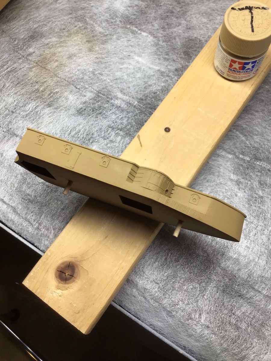
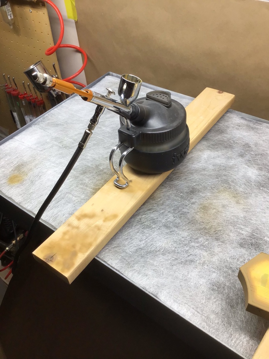
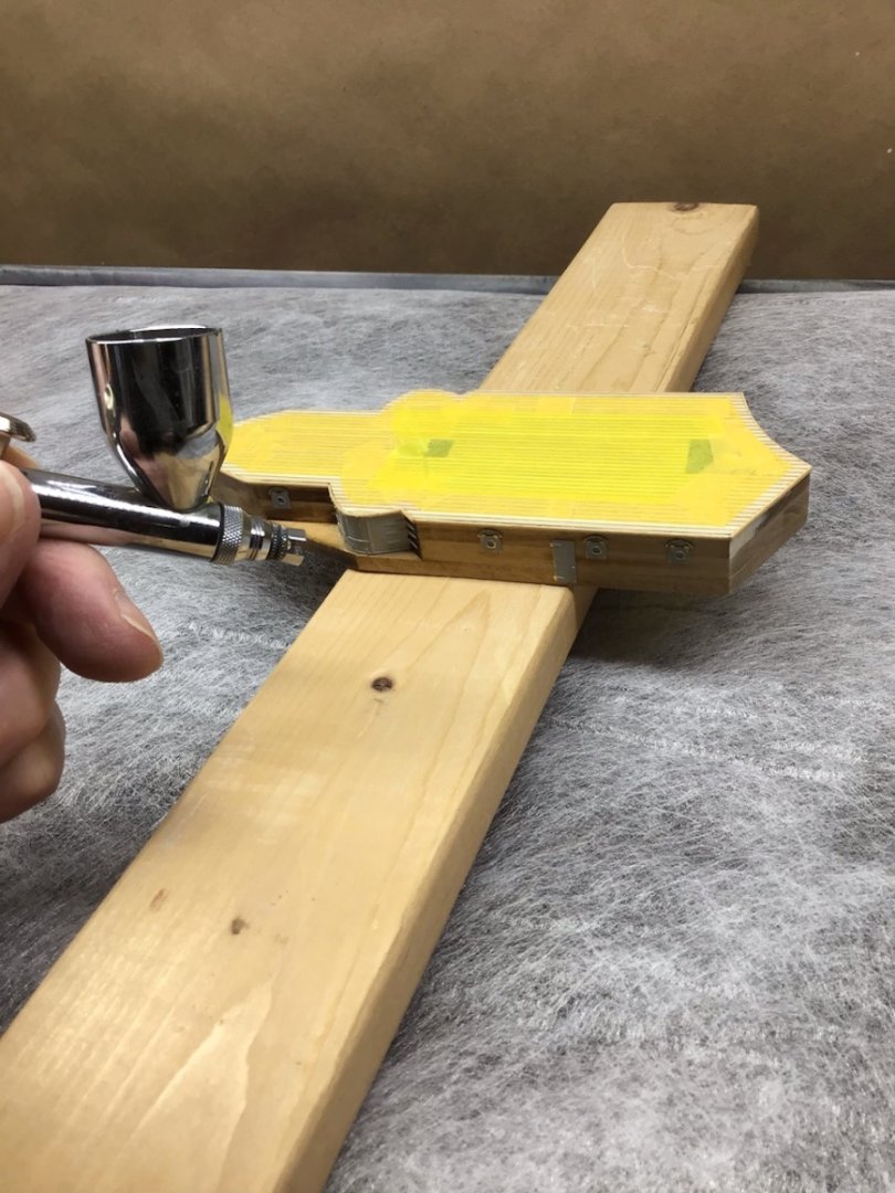
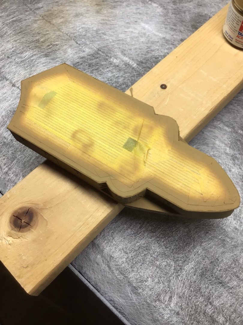
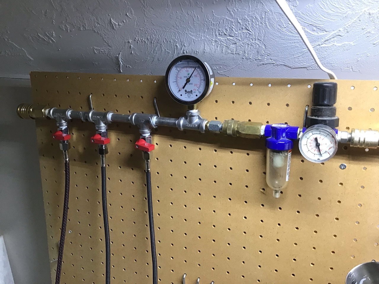
Painting the Forward Superstructure The top was masked, leaving a 1/8” wide perimeter around the outside edge. 1/8” white pinstripe tape was applied first to the super structure outside edge, to act as a spacer, then the Tamiya masking tape along it’s inside edge. The bulkheads were sealed with shellac, and the brass primed with Mr. Surfacer primer. Mr. Surfacer works very well. Plan is to prime the remaining PE sheets with Tamiya primer. In my world, “Buff” is Tamiya Desert Yellow (XF-59), thinned 20% with Tamiya XF-20, and was applied with a Paasche Talon configured with the #2 tip, @20# pressure. My favorite Rickover quote is “the devil is in the details, but so is salvation”. Here the paint reveals gaps between the half round trim and the deck, that needs to be filled in. And notice the end grain along the rounded edge needs to be filled and sanded. I’ll let the paint cure for a few days before this work. Going to give Mr Surfacer 500 a shot for the filler. At the end, Tamiya Airbrush cleaner is run through the brush and exhausted into an Iwata airbrush station. I had my plumber friend make up a manifold with a 0-30# liquid filed gauge for greater accuracy, and ball valves from Paasche, available from Coast Airbrush. The table is by Artograph, shown without the hood.


- 166 replies
-
- 7
-
-
- Maine
- BlueJacket Shipcrafters
- (and 1 more)
-
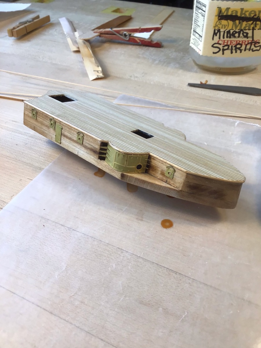
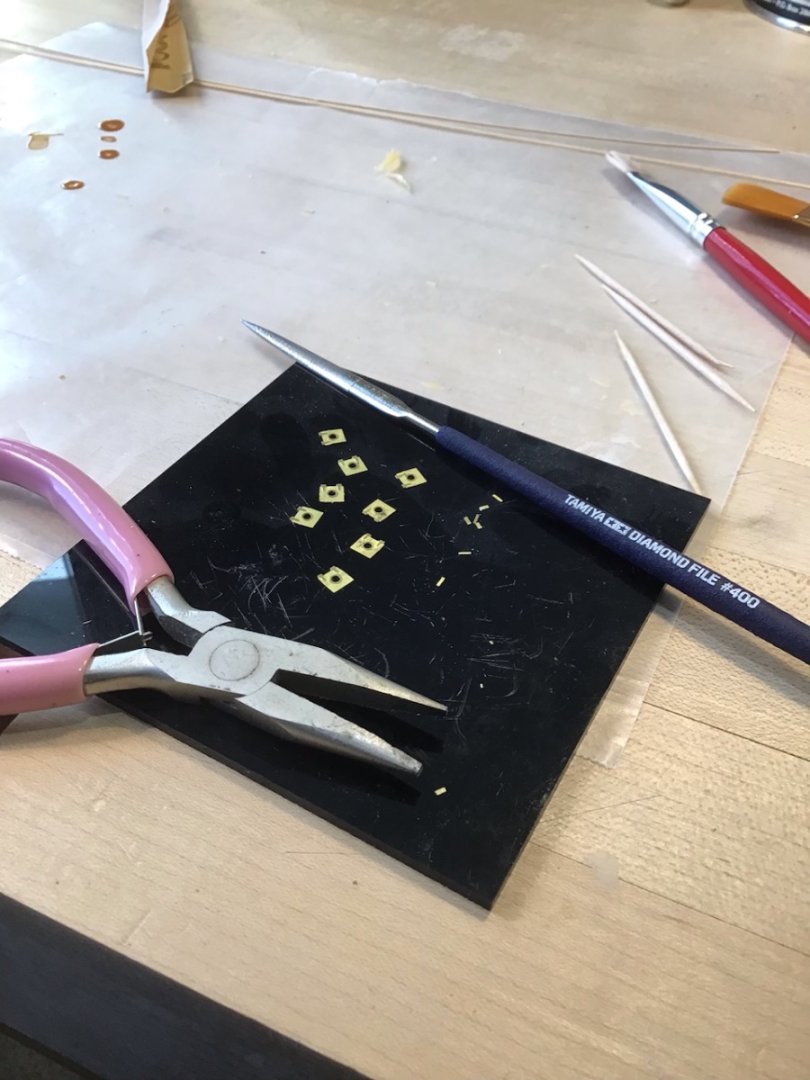
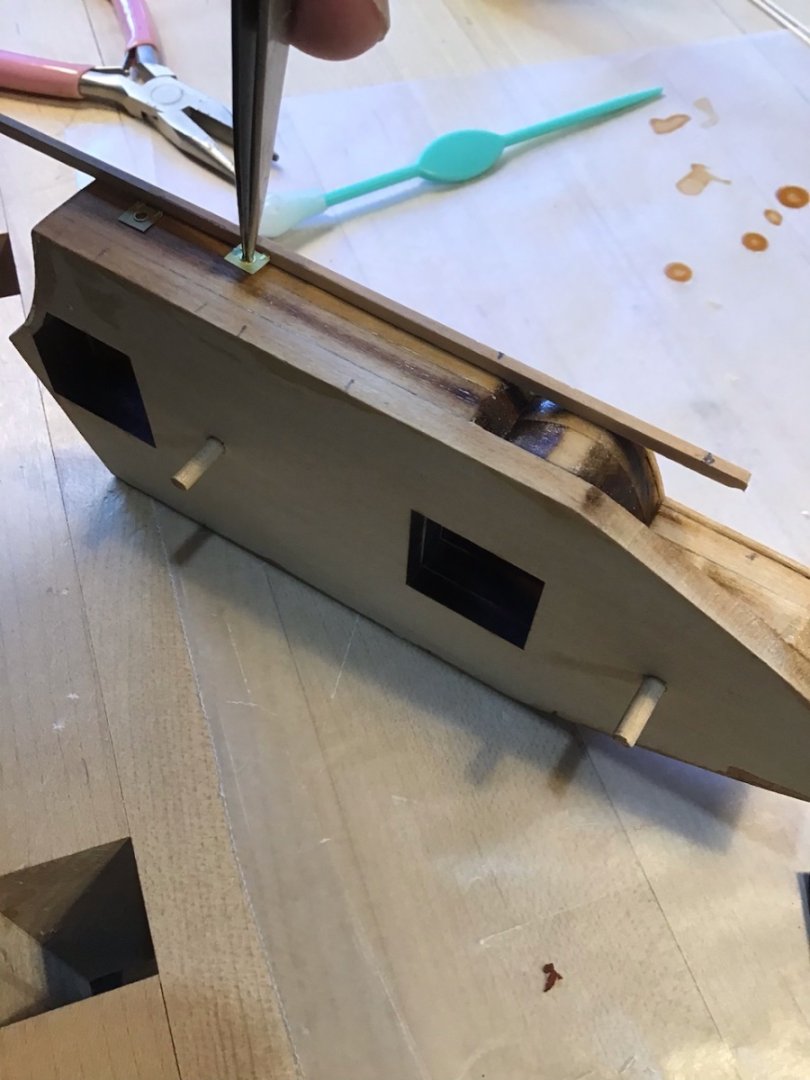
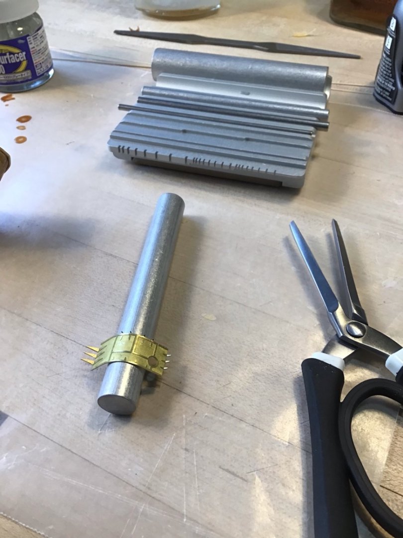
Forward Superstructure Photo Etch Cut the photo etch from the sprue with an Xacto on a hard surface. Clean up the nubs with a diamond file - the Tamiya file has a fine cut and quickly removes metal. To help with vertical alignment use a piece of stock against the half round trim. Notice the pencil marks at the base, to help with fore/aft alignment. The porthole panels were installed first followed by the ringlets. Use a rod to form the 6” gun casement panels. The rod set is from Small Shop. It’s important to get the casement panels shaped correctly so they fit easy along the bulkhead. I needed to file the bottom of the half round trim with a wood file and the casement panel with the Tamiya file. To get the general shape, first hold down the aft end against the bulkhead, then make sure the aft hinges are at the correct angle. Then continue to wrap with the fingers. Next fine tune with the rod by working fore and aft from about the middle of the piece.

- 166 replies
-
- 7
-
-
- Maine
- BlueJacket Shipcrafters
- (and 1 more)
-
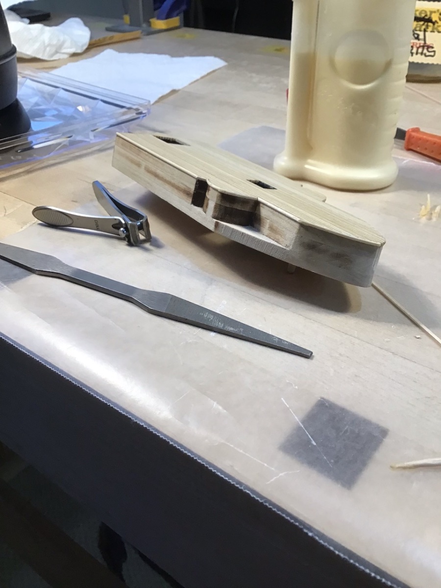
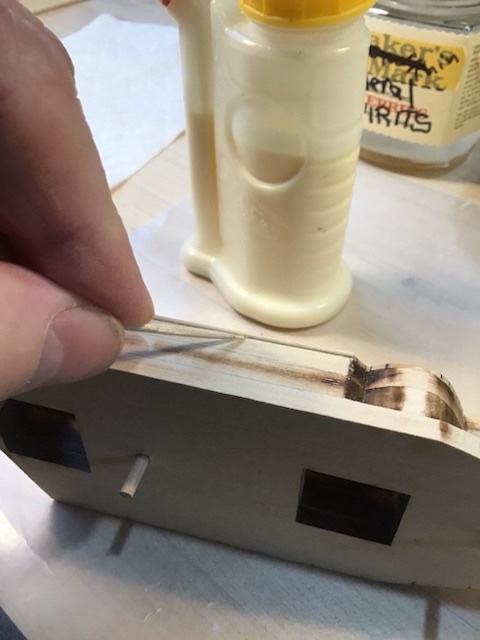
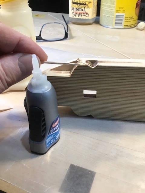
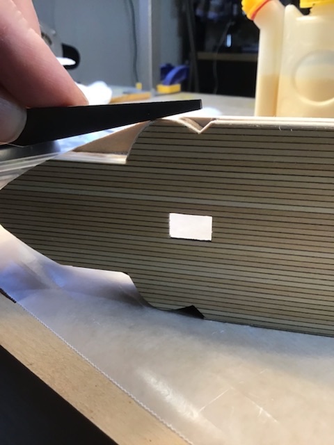
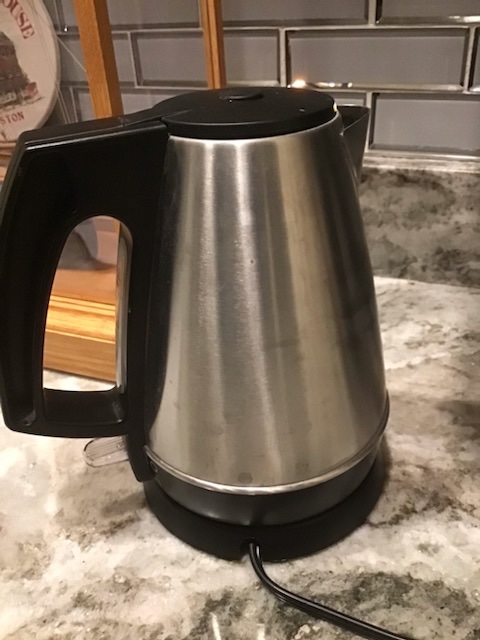
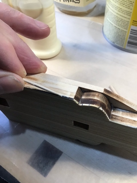
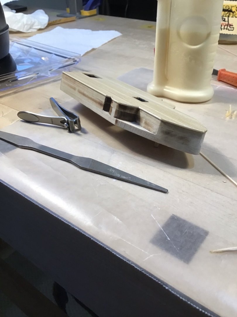
Superstructure Trimming with Half Round Use a toothpick, to apply a thin bead of carpenters glue along the deck edge. Start with a small drop on the tip and roll the toothpick as it’s dragged along the deck edge. After the trim is installed use a new toothpick to cleanup any squeeze out. For curved sections I use an electric tea kettle to generate steam for bending. Several pieces are used to make it around the curve. The first piece brings us halfway around. Superglue is used at the beginning and end of the piece with carpenters glue in between. The next piece brings us to the end of the curve, note the end of the first piece is trimmed at an angle with a flat chisel to make a tight joint. Trim the piece with a nail trimmer. A pattern file is used to dress up the joint. This end of file cuts on the thin edge, the wide side is a safe edge. Rotate the file around the half round to avoid making a flat spot. The results. The pattern file is shown, available from Lie-Nielson in Maine.

- 166 replies
-
- 6
-
-
- Maine
- BlueJacket Shipcrafters
- (and 1 more)
-
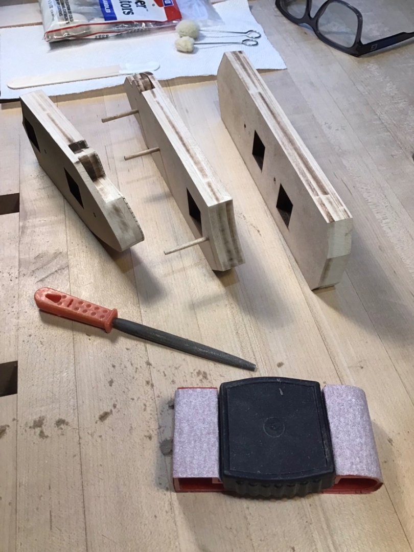
Superstructure Bulkhead Prep Used a half round file and a sanding block to even up, and remove the laser residue along, the bulkhead sides.
- 166 replies
-
- 8
-
-
- Maine
- BlueJacket Shipcrafters
- (and 1 more)
-
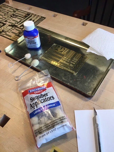
Cleaning the Photoetch Cleaned the PE with Birchwood Casey degreaser. Applied generously with swauber applicator. Bloated dry with a paper towel and buffed with a second dry swauber. Note the AV primer on the props did peel as yvesvidal said, so will be using a different primer.
- 166 replies
-
- 5
-
-
- Maine
- BlueJacket Shipcrafters
- (and 1 more)
-
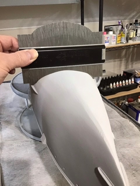
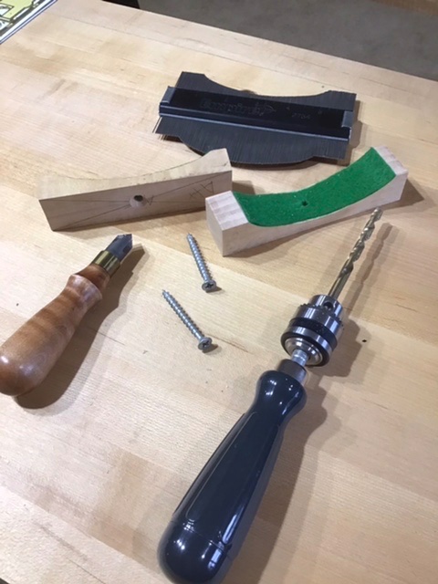
Cradles Made two cradles to hold the hull when marking the waterline. First used a contour gauge to get the hull cross section at the fore and aft screw holes. Next marked two blocks and cutout the semicircular sections with the band saw, and smoothed the curve with the spindle sander. Drilled the holes with a hand drill and made the counter sink in the block with the counter sink tool on the left (available from Lie-Nielson). Last lined the block with green felt. Blocks installed. Looks like the forward block bottom needs to be cut down a bit. I’ll do that on the Byrnes table saw.
- 166 replies
-
- 7
-
-
- Maine
- BlueJacket Shipcrafters
- (and 1 more)
-
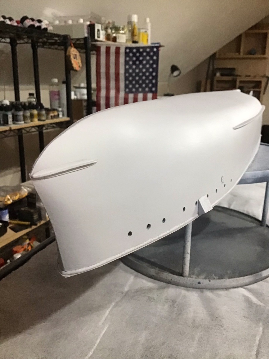
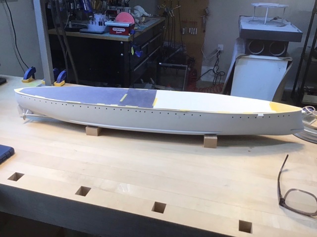
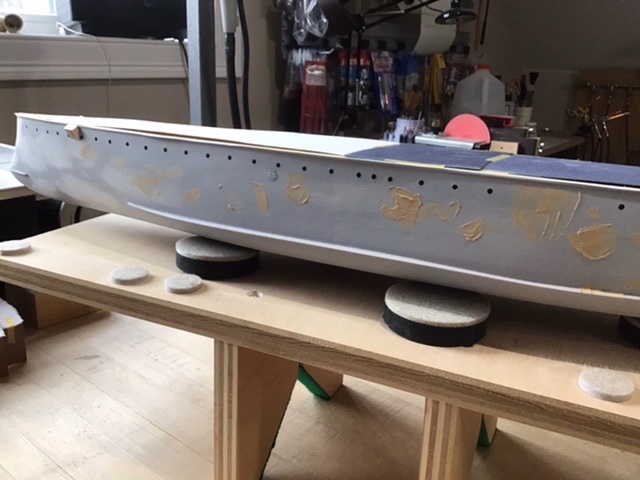
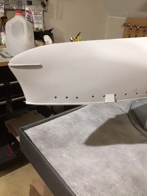
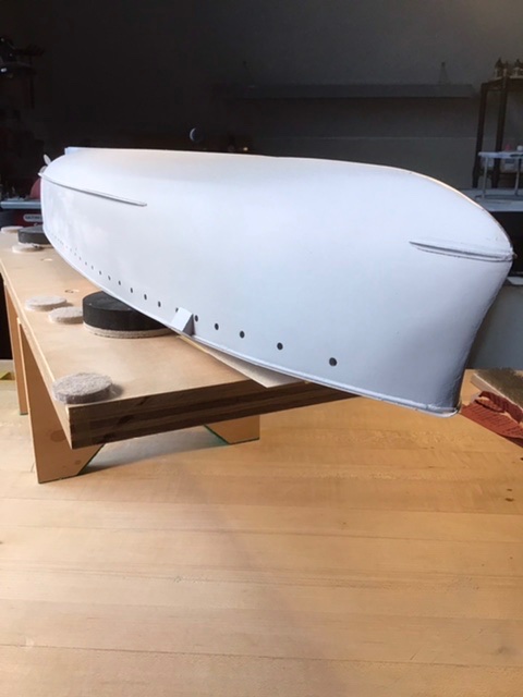
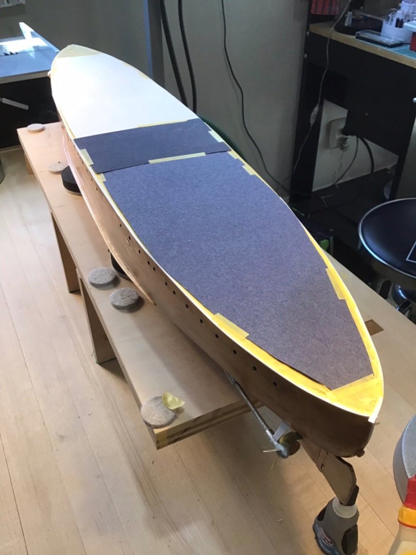
Prime Coat - Four More Times Applied four more coats of primer. Between each coat, first sanded with 400 grit to remove bits of dust or paint droplets. (There is a droplet above and to the left of the sandpaper) Then patch defects with plastic wood applied with an x-acto spade blade, then sand smooth with 320, then 400 grit. Vacuum the dust and wipe with a cotton rag. Two views of the hull, ready for the color coat.
- 166 replies
-
- 9
-
-
- Maine
- BlueJacket Shipcrafters
- (and 1 more)
-
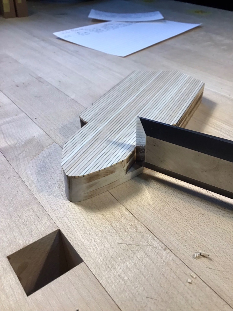
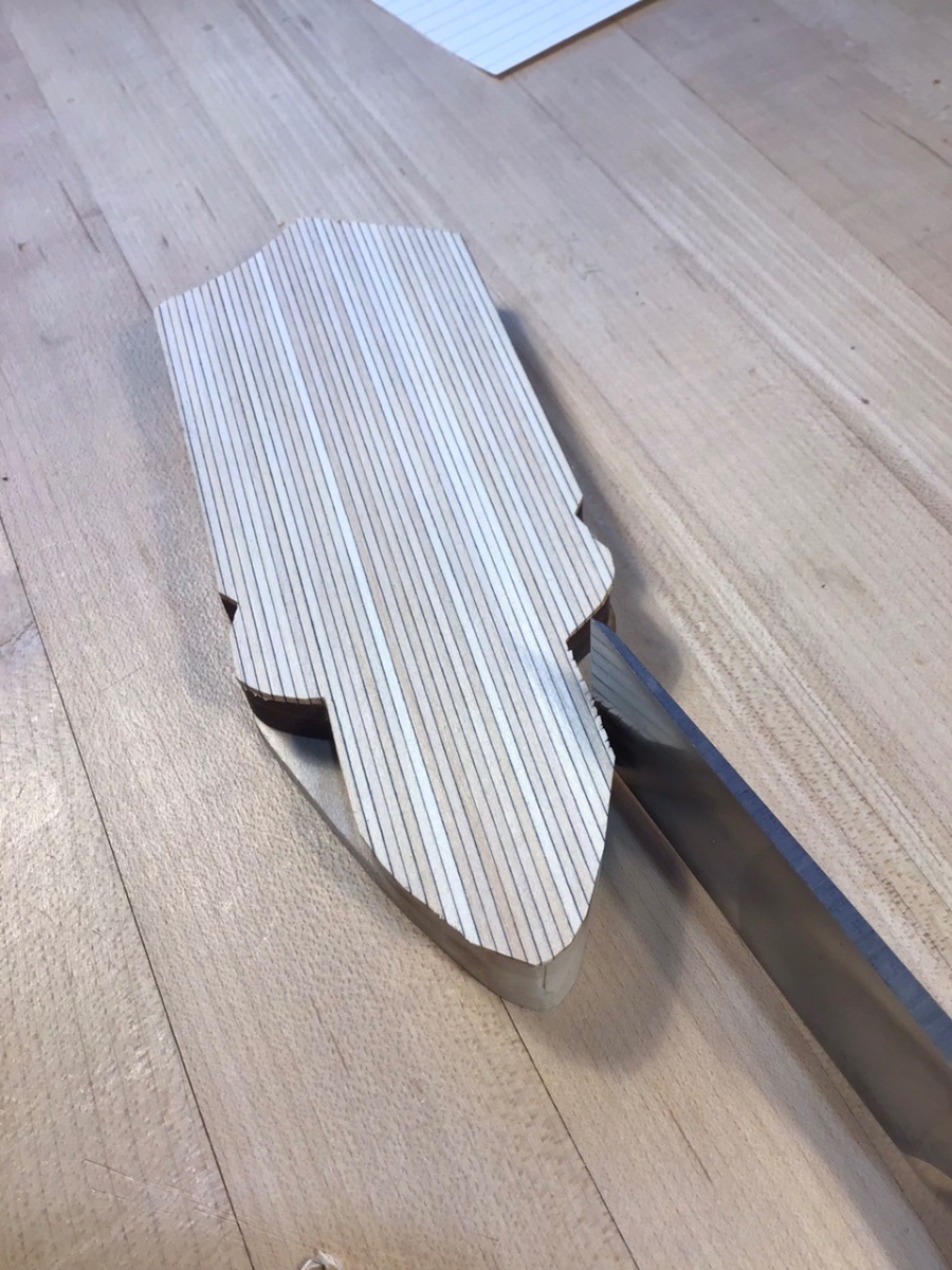
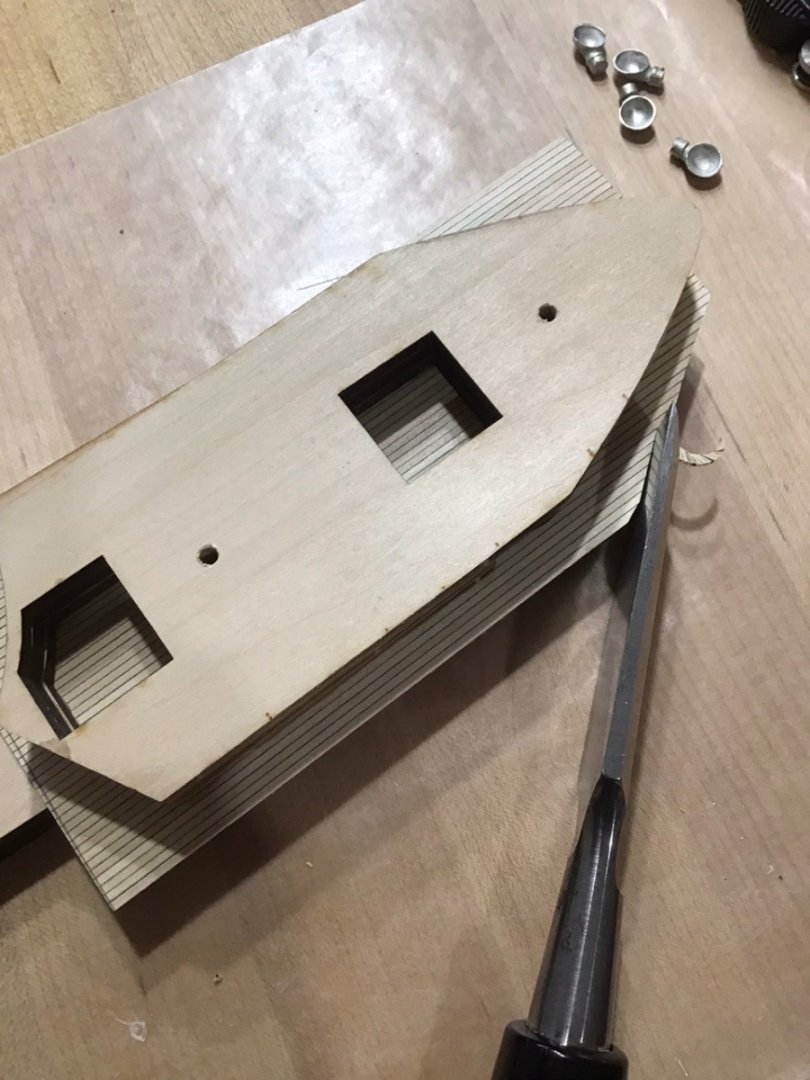
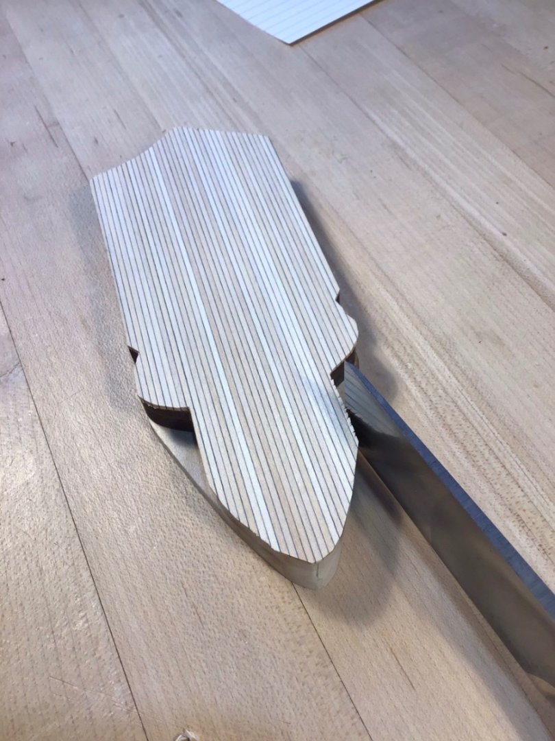
Forward Superstructure Deck Glued a piece of deck to the superstructure. Next is to trim the deck flush with the sides. Flush trim bit on the router table was a thought, but flat chisel is the way to go. Chisel will easily get into the corners. The chisel needs to be very sharp. The method is to use the superstructure sides to guide the chisel. Below it’s kind of fun to scoop off pieces of wood. An instructor once described it as cutting down hill. Be careful on the long sides, the wood may split across the top of the deck. Below the chisel is used to make small perpendicular “relief cuts” and the superstructure “stops” the chisel. Finally the chisel can cut off the nubs, using the superstructure side as a guide.

- 166 replies
-
- 8
-
-
- Maine
- BlueJacket Shipcrafters
- (and 1 more)
-
Now that is really cool! Love Dark Green hull. Great to know, thanks.
- 166 replies
-
- 2
-
-
- Maine
- BlueJacket Shipcrafters
- (and 1 more)
-
Thanks. Have used the products for many years on mixed media aircraft (plastic, PE, metal, resin), as well as wood ship models. Never had a bad result.
- 166 replies
-
- 4
-
-
- Maine
- BlueJacket Shipcrafters
- (and 1 more)
-
Good Morning, Let’s interpret that drawing. Consider the dotted lines on the plates. A dotted line means there is an edge underneath the plate. The first copper strake above the keel has dotted lines on the bottom. So the keel plates are underneath. The forward plate is a trapezoid, the lower edge has a dotted line, the forward edge does not. So it looks like a butt joint on the forward edge. Looking at the second strake up, not sure what is happening with dotted lines, thick lines here. The next third strake up has dotted lines on the top edge, meaning plates above tuck under the top edge, rather than the bottom. So what to do? Consider the dimensions of the overlap are so small, at this scale it would be invisible to the eye. It’s your ship, build it the way you like. The reality is there can be a big difference between drawings and as built. No amount of research and drawings can account 100% for what happened in the shipyard during construction. It’s impossible to know how everyone practiced shipbuilding over hundreds of years. For me it’s about time and practicality. If something isn’t visible, or an observer wouldn’t notice, I don’t spend time doing it. When I do get around to doing this I’ll probably use butt joints everywhere and just reduce the plate width to account for the overlap. Have fun with it.
-
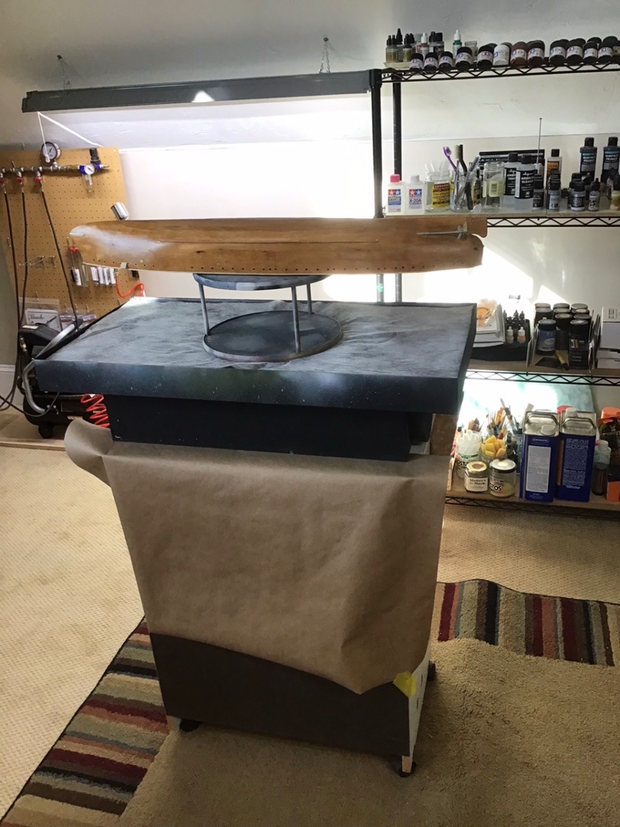
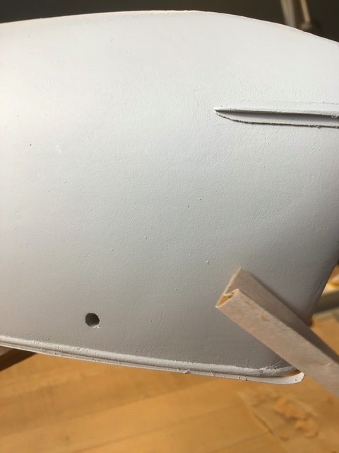
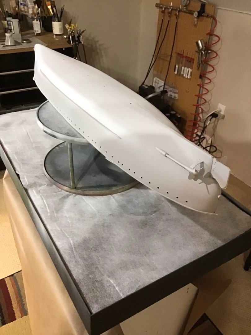
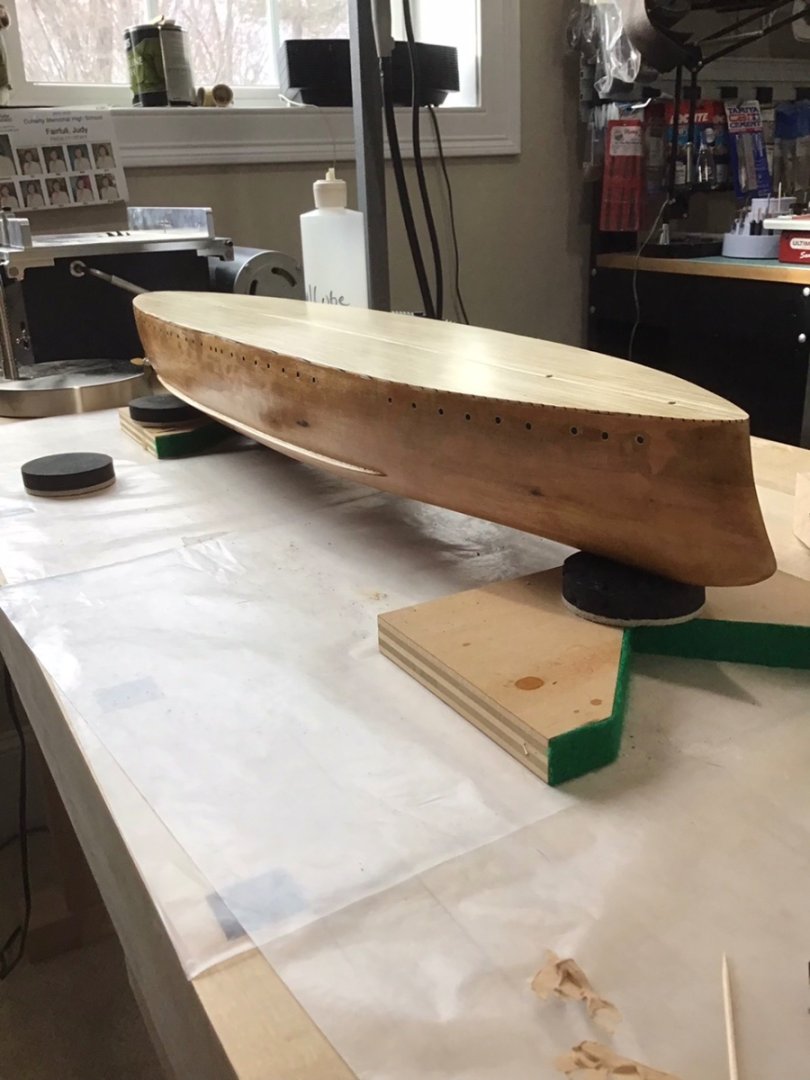
Priming the Hull Before priming the anchor bills, ram stiffeners, and torpedo tube covers were installed, along with the half round trim along the deck edge. First the deck was masked with tape and construction paper. The hull was positioned upside down on a lazy Susan, on the Artograph table. Vallejo grey primer, thinned with Vallejo thinner was applied with an Iwata RG-3 mini gun, @20 psi. Smoooooth…. Let dry overnight. Vallejo is an acrylic primer that adheres well to shellac, metal, and brass.


- 166 replies
-
- 12
-
-

-
- Maine
- BlueJacket Shipcrafters
- (and 1 more)
-
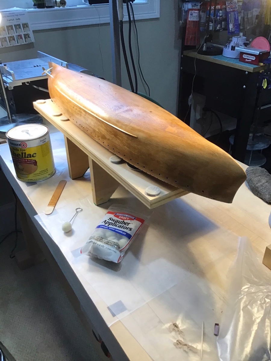
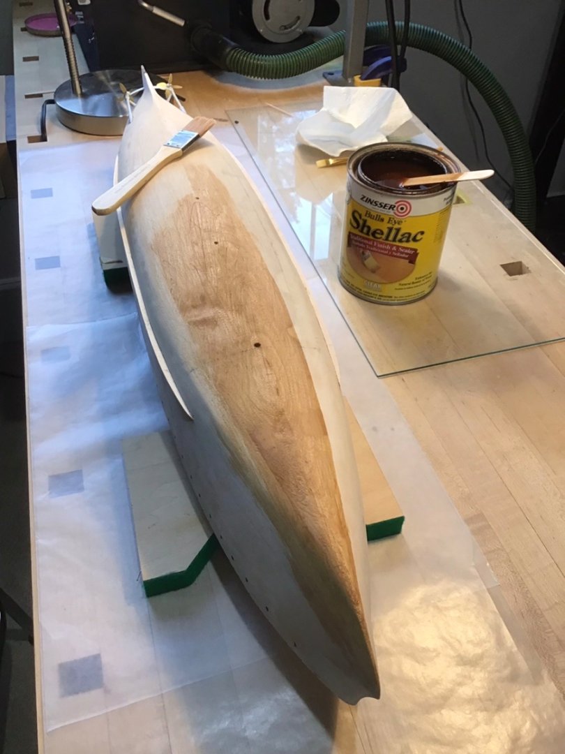
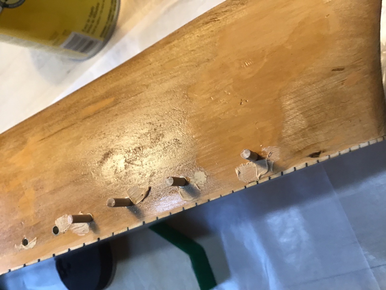
Sealing the Hull Zinsser Bulls Eye Shellac was used to seal the hull. It’s an evaporative finish, and the alcohol base dries very quickly. And additional coats easily blend into the finish. Here the hull is upside down to avoid masking the deck. Wood dowels were used to keep Minwax wood filler out of the port holes. Shellac also does a good job filling minor imperfections. Swauber Applicators help when applying shellac around the portals and along the lower edge. Looking good after a rundown with steel wool. A few drips and runs, shellac dries into a hard finish, were removed with fine flat and round files.

- 166 replies
-
- 7
-
-
- Maine
- BlueJacket Shipcrafters
- (and 1 more)
-
Good luck Avi! 😎
-
Hi Avi, My steps were: Minwax stain, lite pass with steel wool, then airbrush. The black and copper are Tamiya, and the white is Vallejo. The black and copper were applied with an Iwata RG3 Minigun and the white with a Paasche Talon. The minigun can deliver a high volume of paint and quickly covers large surface areas. In my view we are dealing with small boards, so stain is enough to seal the fibers without creating a surface finish that completely eliminates the grain. Apply the stain carefully, apply just the right amount so all of the stain is absorbed, wipe off any excess quickly. It seems like the sealer and primer are creating a finish that completely eliminates the grain. Water absorption causes wood fiber swelling - the fuzzies. Minwax stain (not water based) causes very little swelling, hence the lite cleanup with steel wool. Next is the paint. Thinning the paint is important. For Tamiya, I learned from Mike’s Hobby Headquarters to start with a fresh bottle, then top it off with thinner. I don’t think Tamiya has a lot of water in their acrylic formula, so it yields a nice smooth, rich texture, with wood grain slightly visible.. The same seems to be true with Vallejo, about 1/3 thinner in the cup works for me. All of this gives a very thin finish. That probably can’t be sanded, I never tried. Hope this helps. Cheers
-
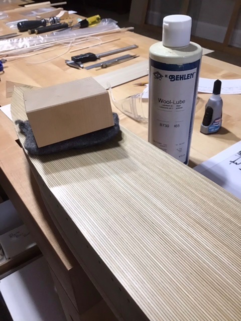
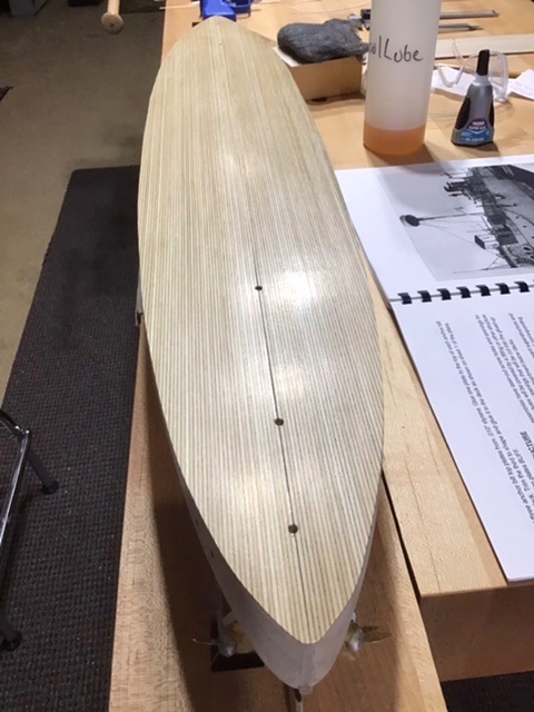
Final Deck Finish By this point applied 3 or 4 thin coats of varnish. Hit the first coat with steel wool. Later coats were applied without sanding in between. I want a good seal because later the waterways will be painted on the deck. No matter how carefully I apply varnish, there always seem to be visible brush stokes. Also I believe the glued up decking is pine, not sure, which can take a finish unevenly. So to “finish the finish” rub down the deck with 0000 steel wool and a product called “Wool-Lube”, it’s a lubricant for the steel wool. It kind of slows down the cutting action of the steel wool, making it harder to cut through the varnish. A wood block over the steel wool helps even the surface. The lube is water soluble, so wipe down the deck with a damp cloth.
- 166 replies
-
- 8
-
-
- Maine
- BlueJacket Shipcrafters
- (and 1 more)
-
Hi Avi, Lite pass with steel wool may be all that’s needed after sealing. I’ve had some good results painting over Minwax natural stain with Tamiya and Vallejo acrylics. My personal preference is to leave the surface slightly rough so the imperfections of the wood and seams remain, so the observer knows it’s wood. Cheers
-
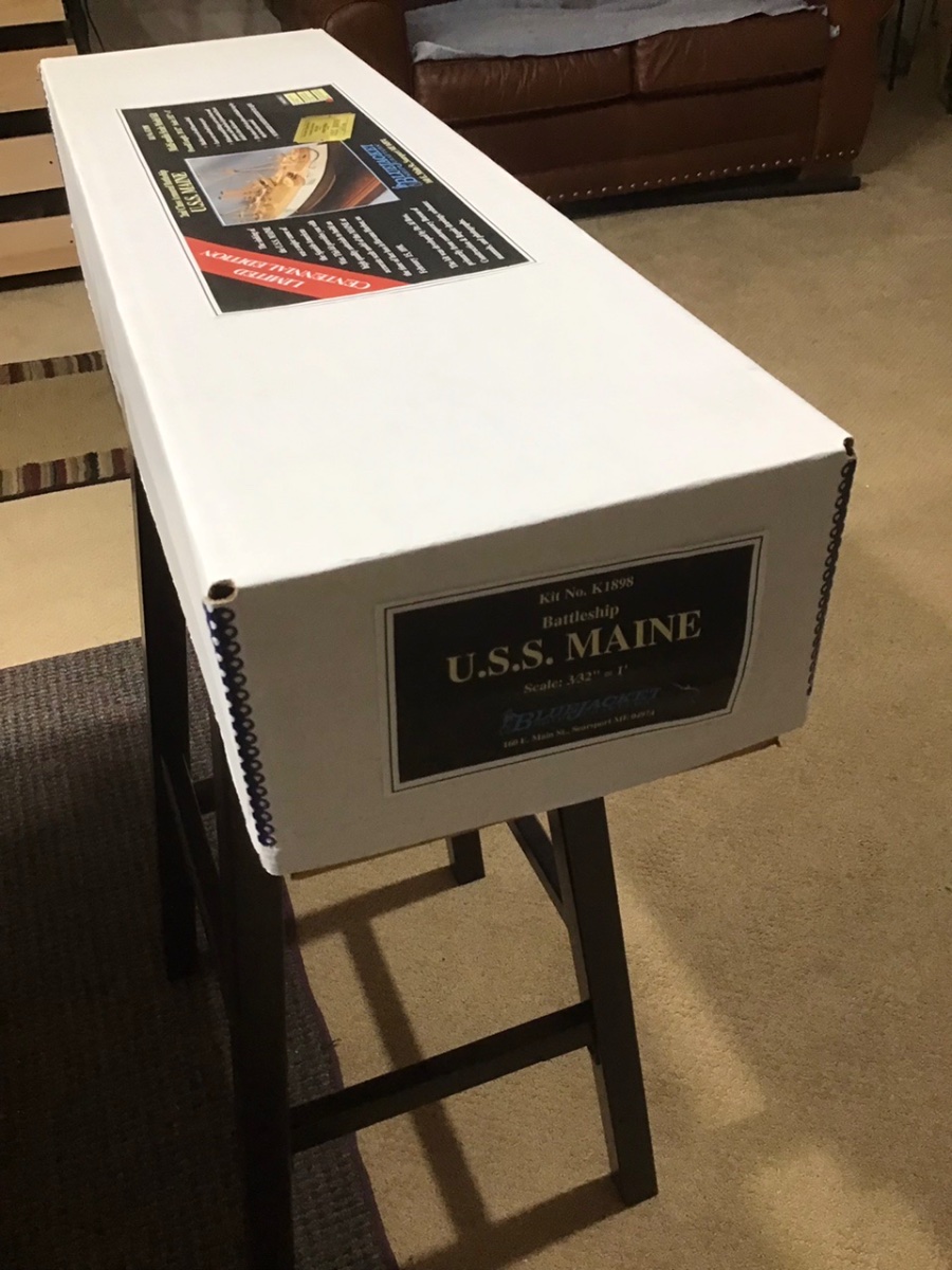
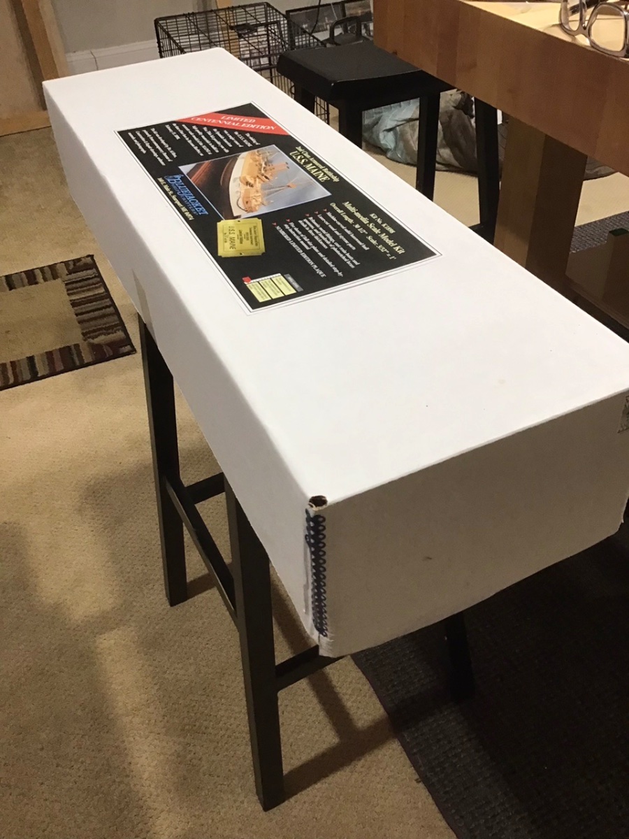
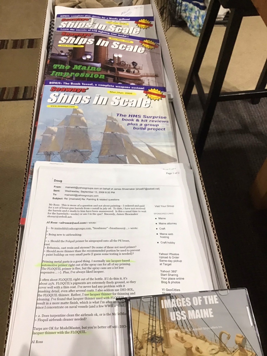
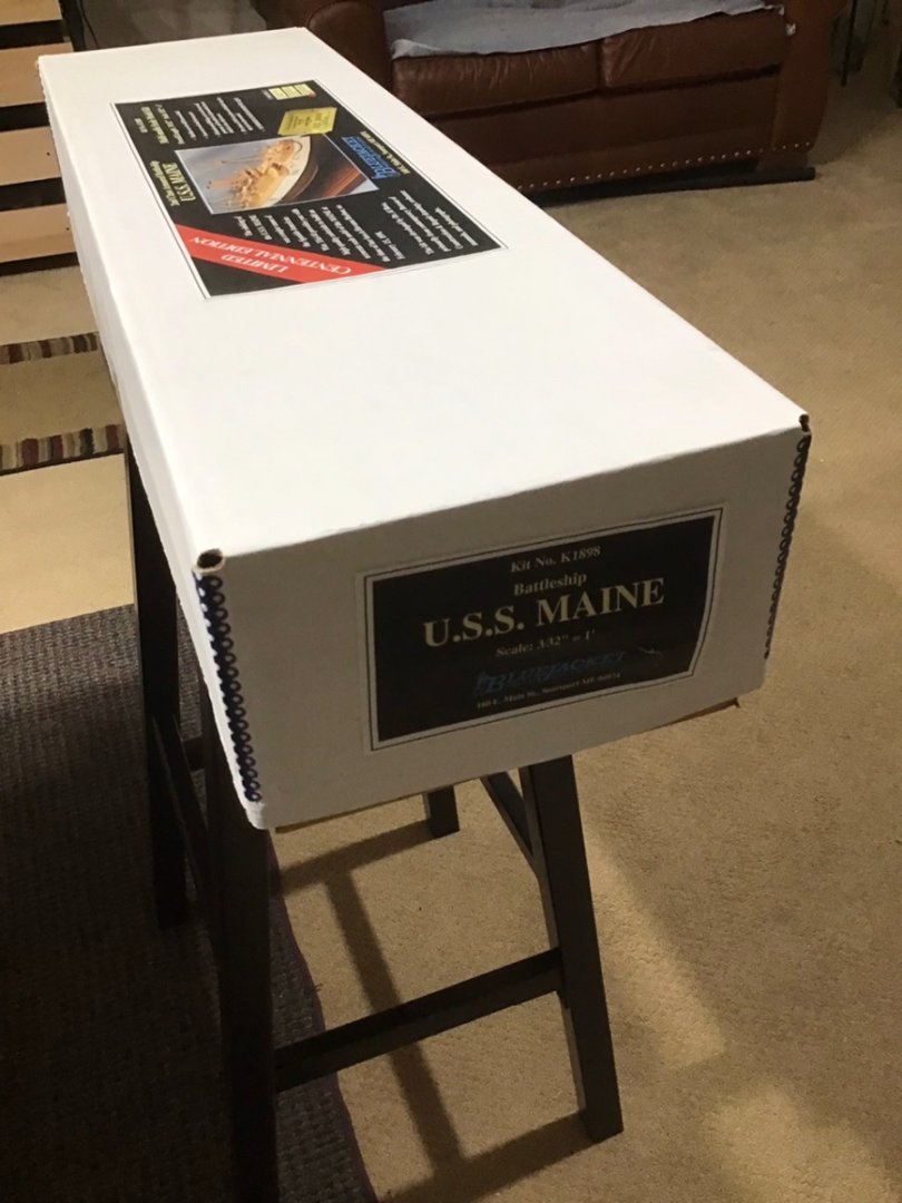
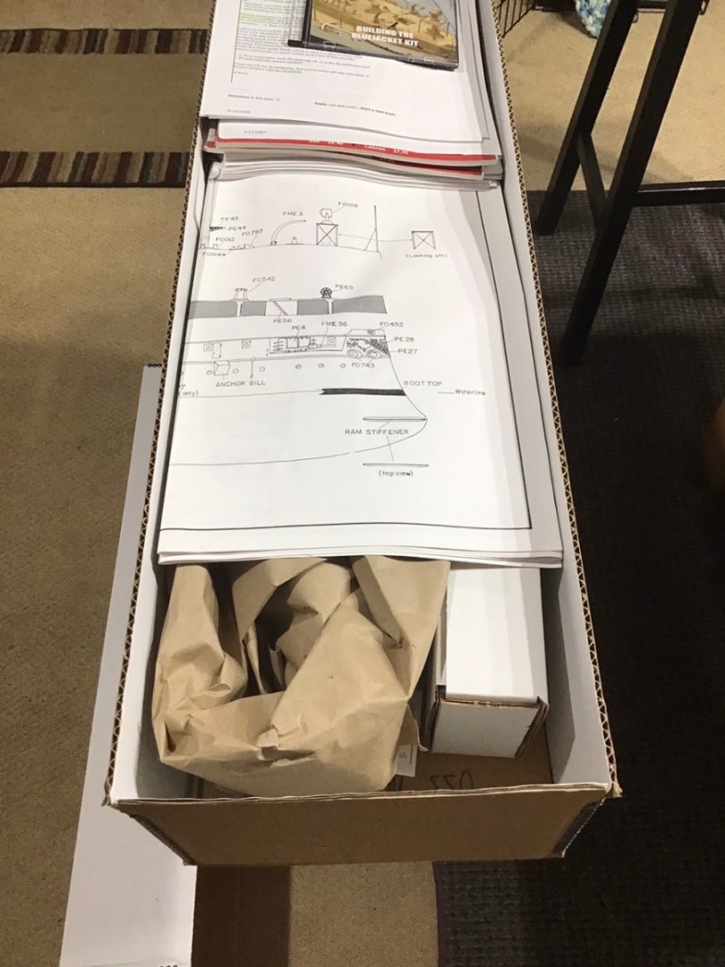
Hello, I have Kit #88 of 100. The box is in great shape and the contents appears to never have been unpacked. Included is reference material collected by the previous kit owner including: 3 copies of Seaways Ships in Scale from 2008 and 2009 with articles about the kit and several email messages that are correspondence between a Yahoo Group of Builders and Dr. Al Ross the designer. I did pay a premium for the kit, please send a private message if interested.


-
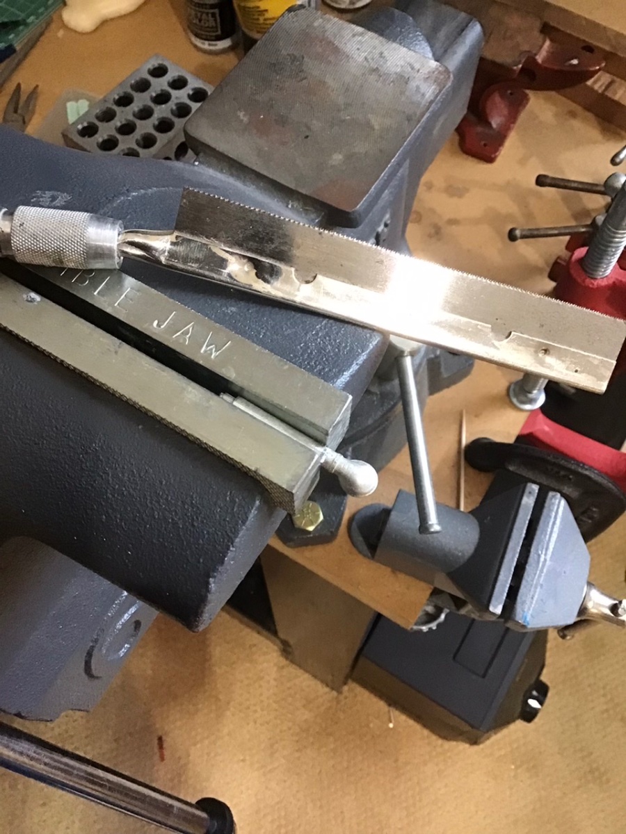
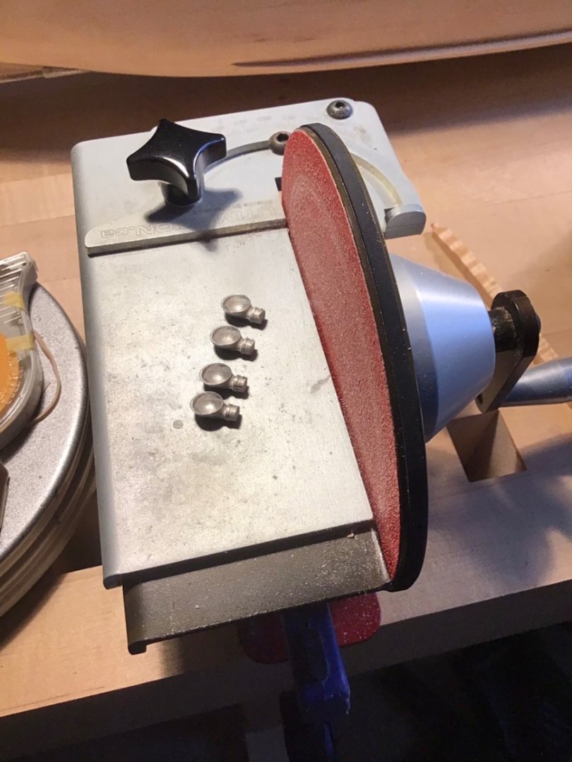
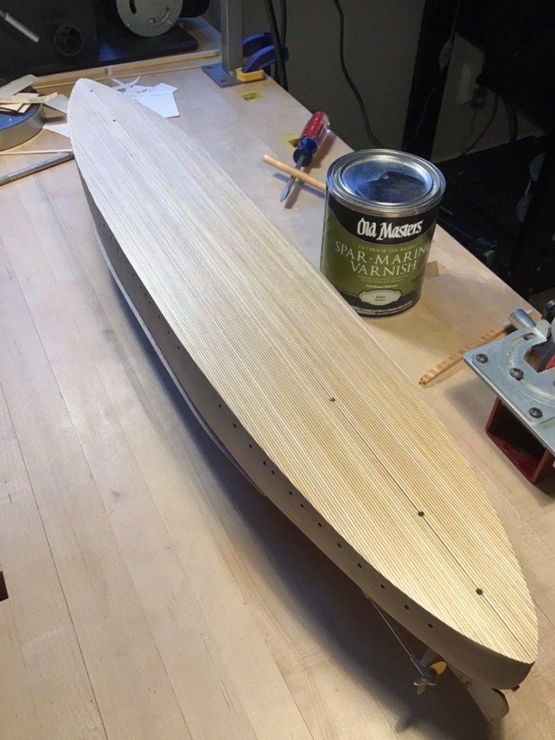
Turret Cowl Vents and Deck Varnish Need to trim the turret vents to length shown on the plan. Found the best way is to put the part in a vise and trim with an Xacto saw. Mark the line with a pencil and position the part in the vise so the line is exposed, then use the vise edge as a guide. Then used the Ultimation sander to even up the parts. Turret vents in place. Applied a second coat of Spar Varnish, will smooth with 0000 Steel Wool and apply a final coat.

- 166 replies
-
- 10
-
-
- Maine
- BlueJacket Shipcrafters
- (and 1 more)
-
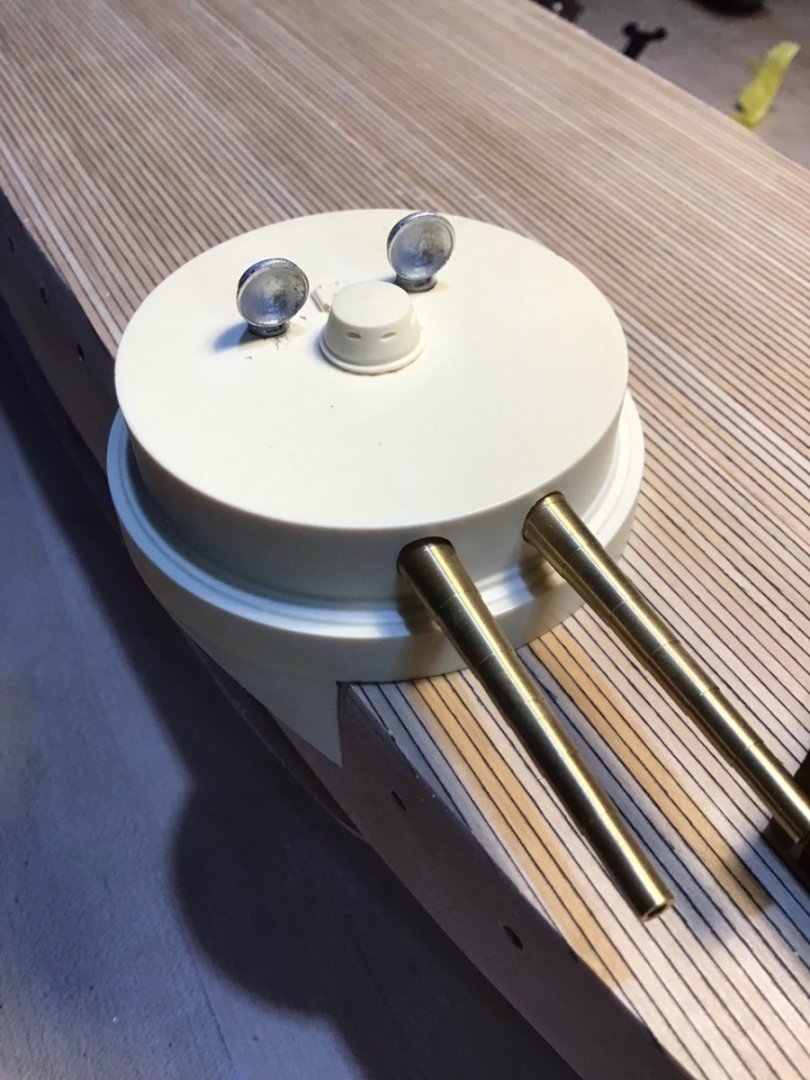
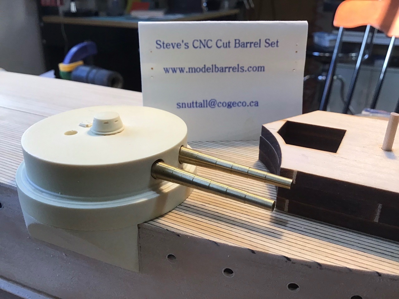
Custom Gun Barrel Fitting Enlarged the turret ports slightly, again with the Foredom, to accommodate the custom gun barrels - provided with this kit purchased from a third party. They are slightly longer than the kit provided barrels.
- 166 replies
-
- 9
-
-
- Maine
- BlueJacket Shipcrafters
- (and 1 more)