
ERS Rich
-
Posts
761 -
Joined
-
Last visited
Content Type
Profiles
Forums
Gallery
Events
Everything posted by ERS Rich
-
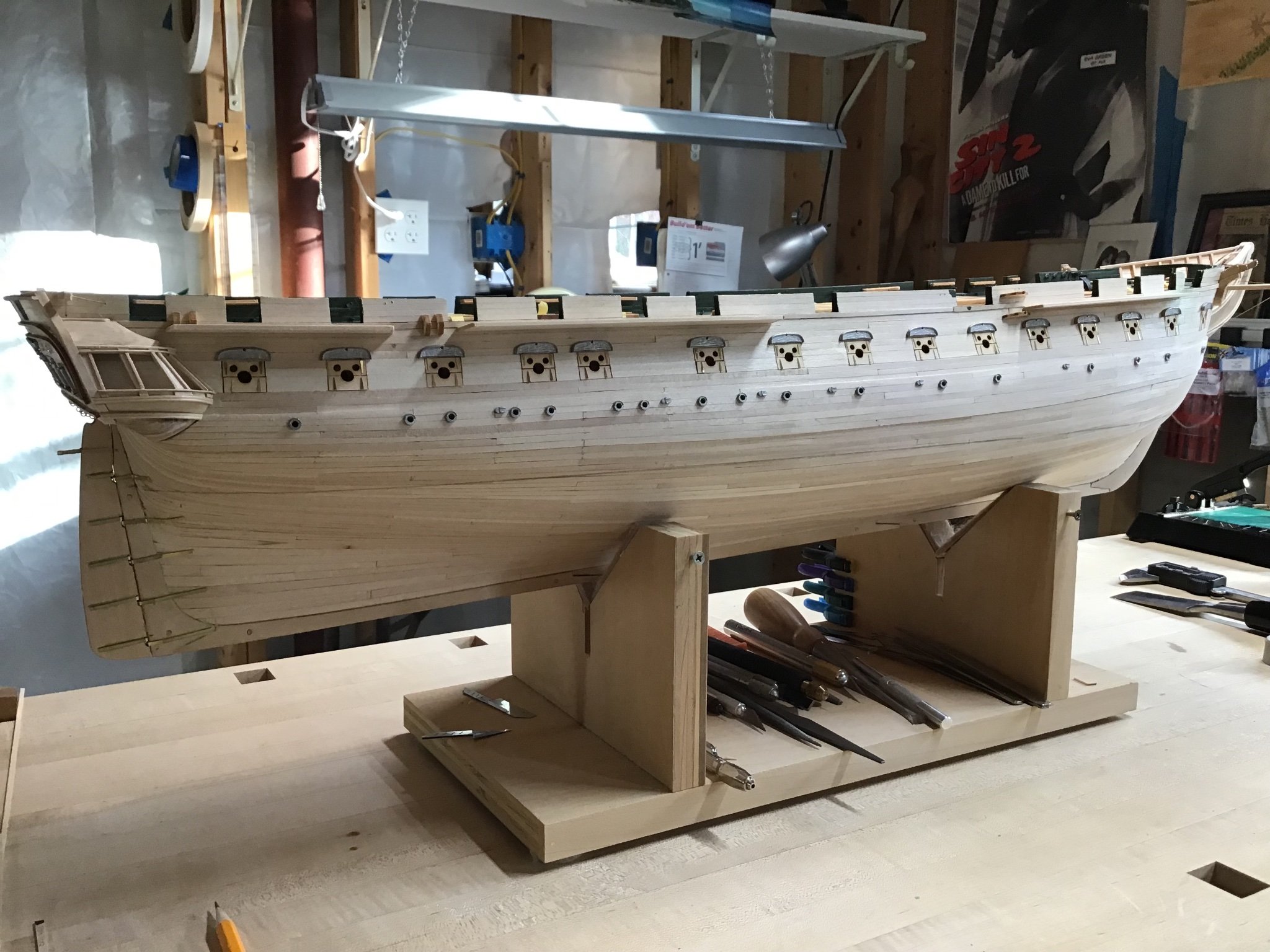
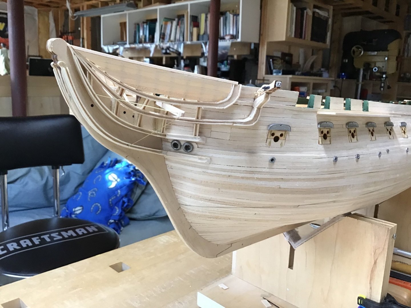
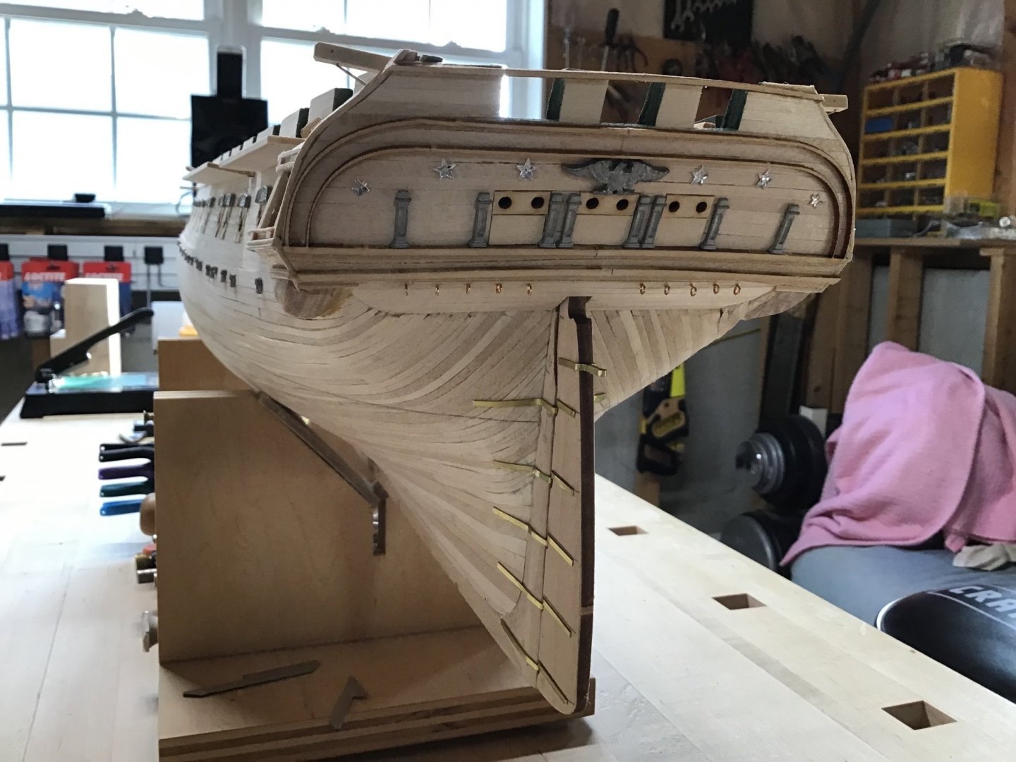
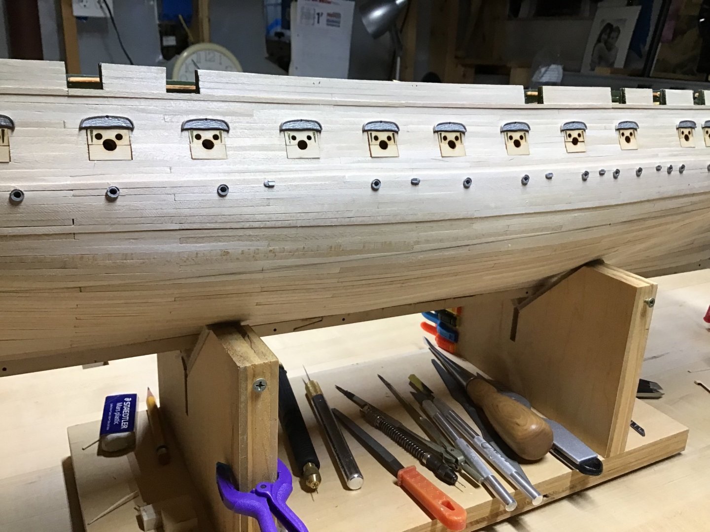
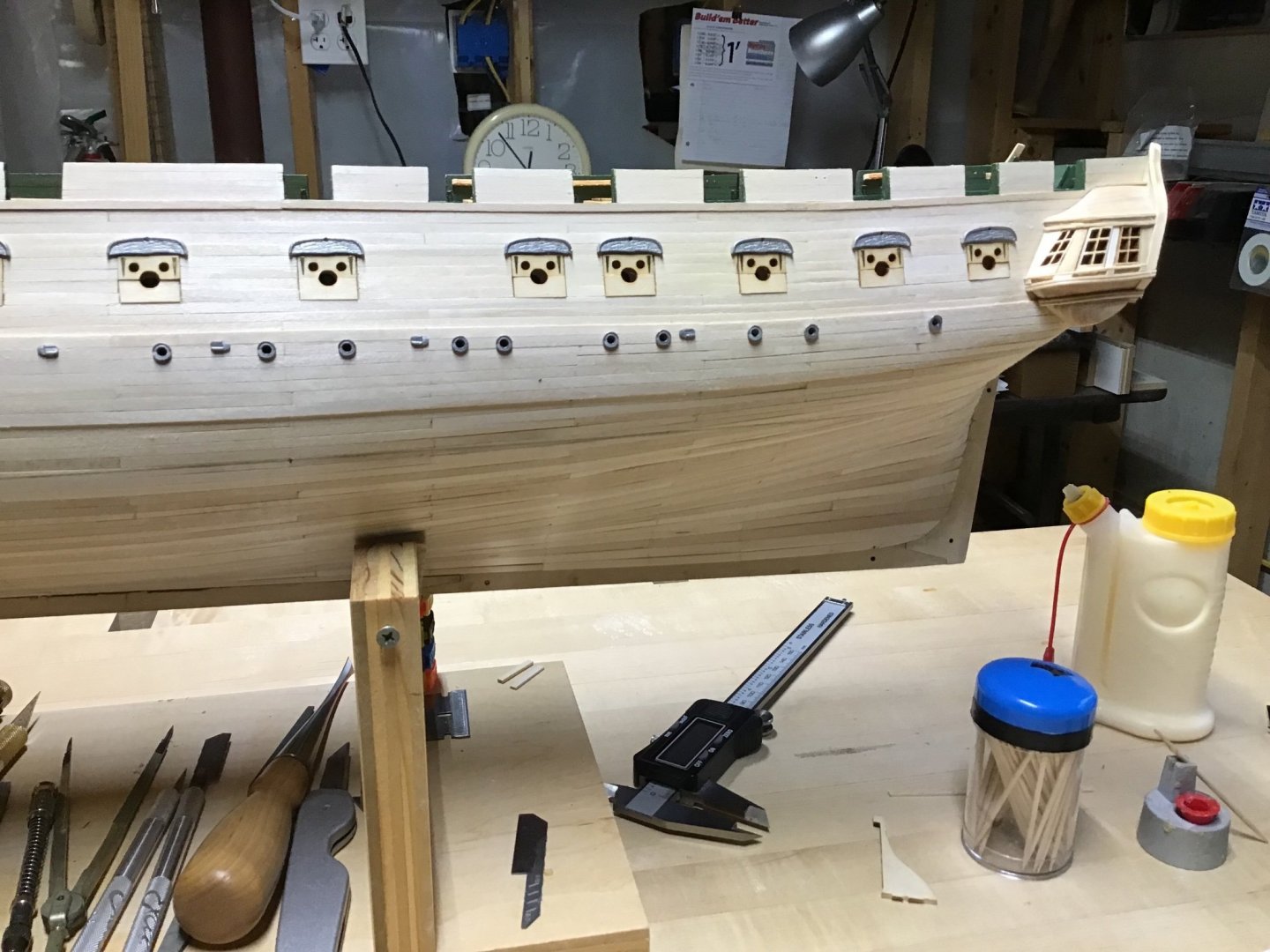
 Hull Construction Complete Just about a year since the beginning and the hull is ready for finishing. All hull construction is complete. A major milestone. What a learning process to say the least. Looking forward to finishing the hull. Merry Christmas!

-
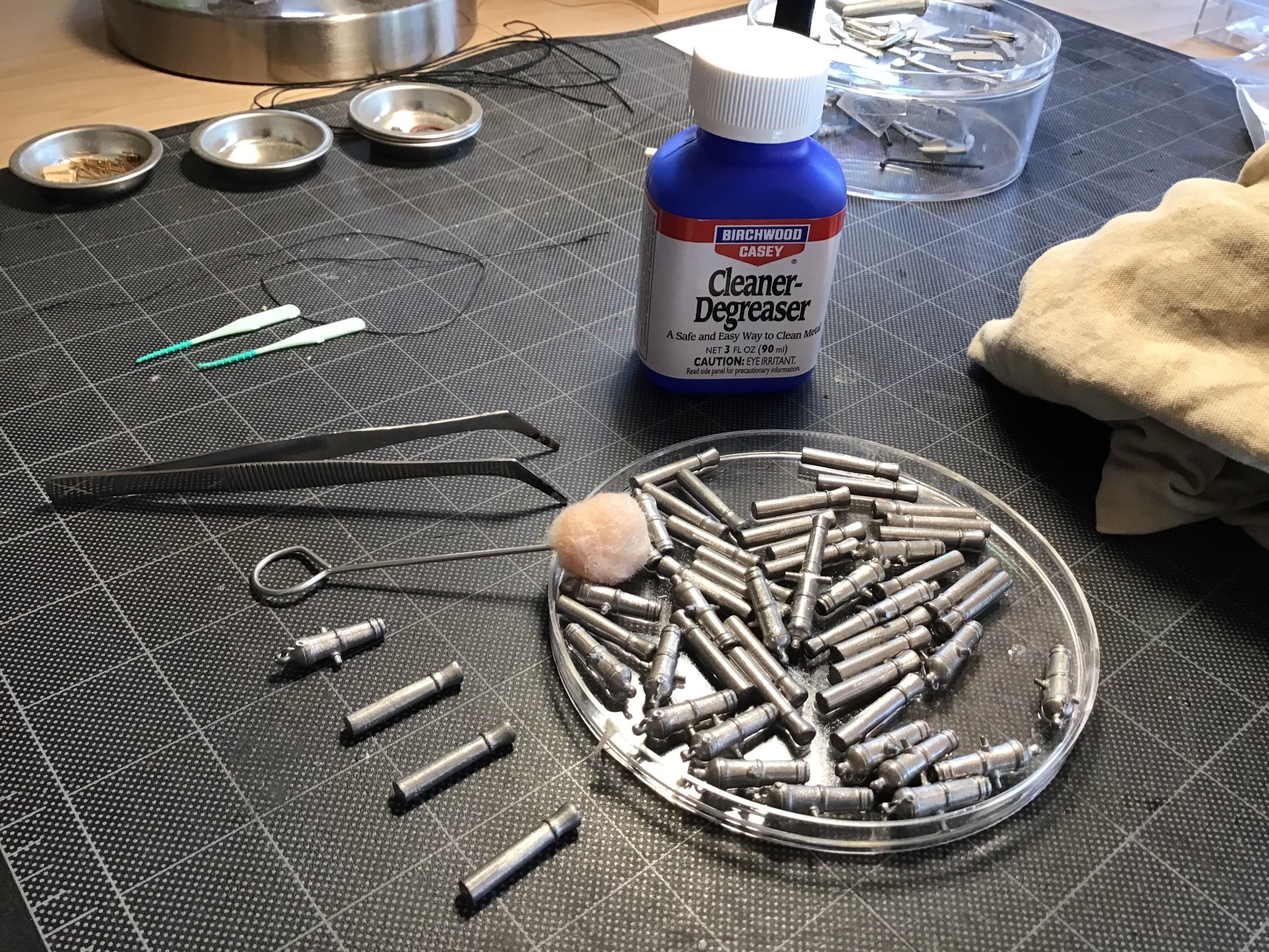
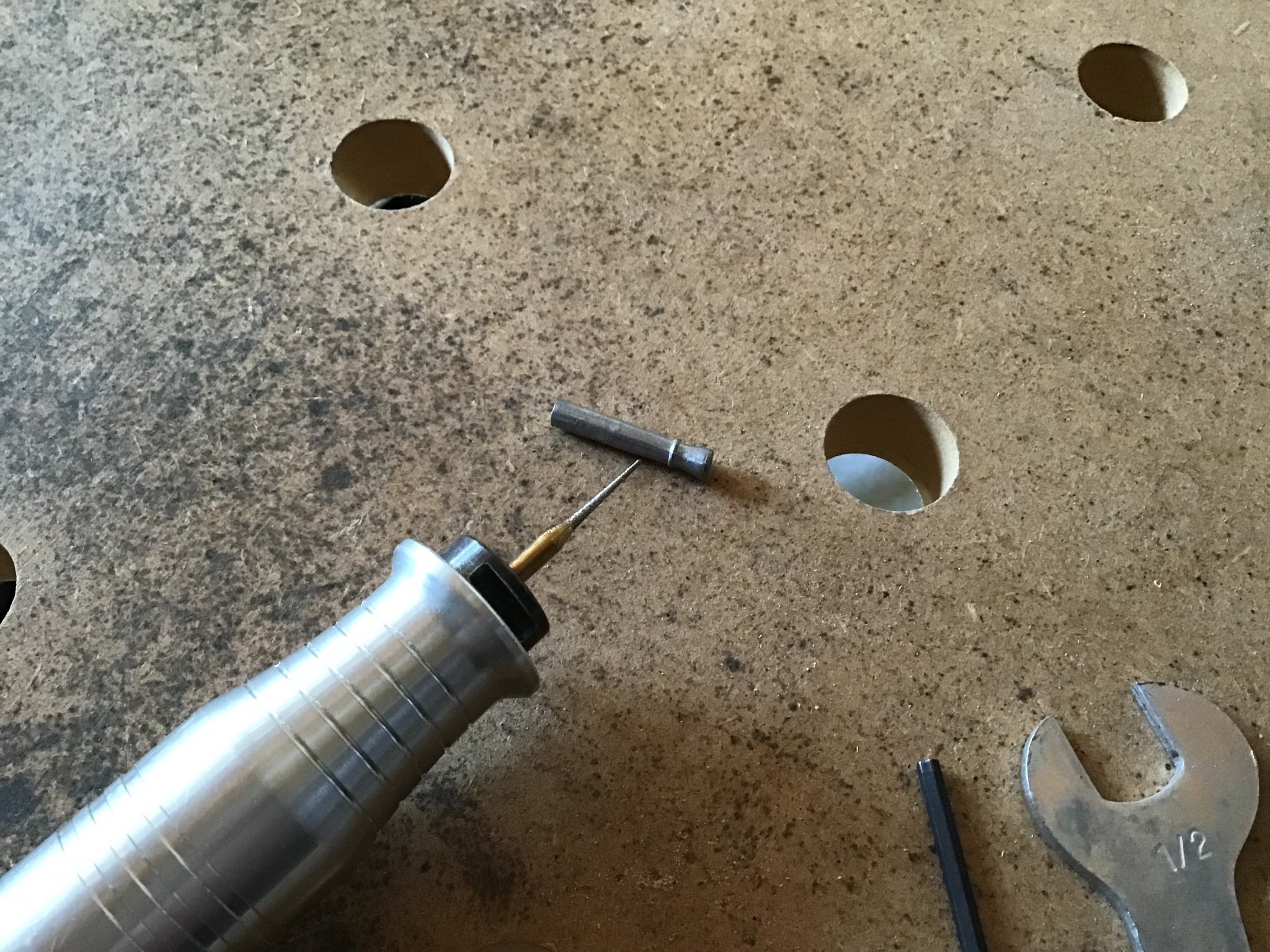
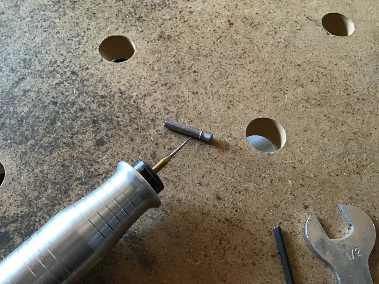
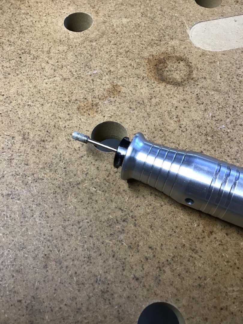
Prepping the Gun Barrels The gun barrels were cleaned with a Degreaser. Then the parting lines on the barrels were removed using a diamond bur in the Foredom tool.

-
Gunport Lids and Brows Cut all the hinges from the frets using an xacto knife on the base of a Small Shop Hold and Fold. Then fixed the hinges to the lids with a tiny dot of CA applied with a toothpick, made a tiny dot on the lid, then used tweezers to place the hinge. The upper lids fit perfectly. The lower lids just needed to be trimmed on the bottom edge and this was done with the Byrnes Saw and the Sliding Table. The brows were fixed with 5 minute epoxy being careful to align the hole in the brow midway between the gunport sides.

-
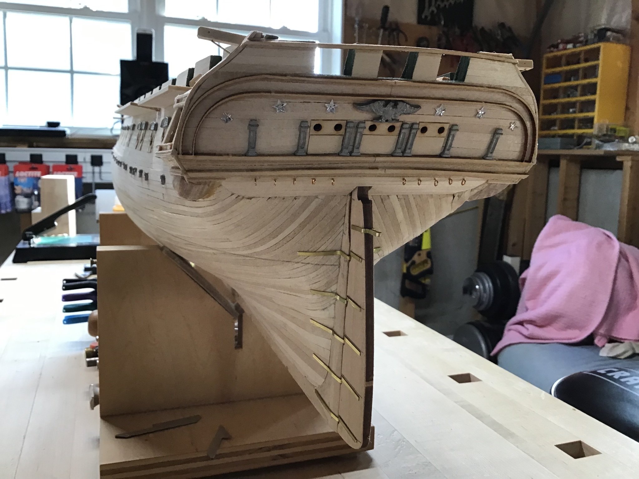
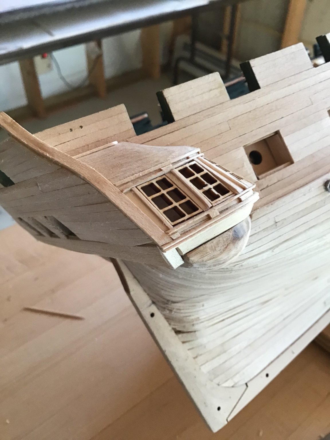
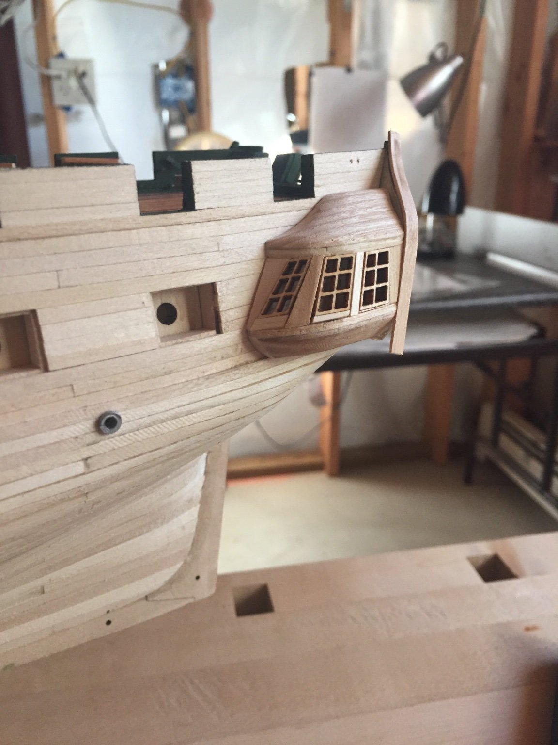
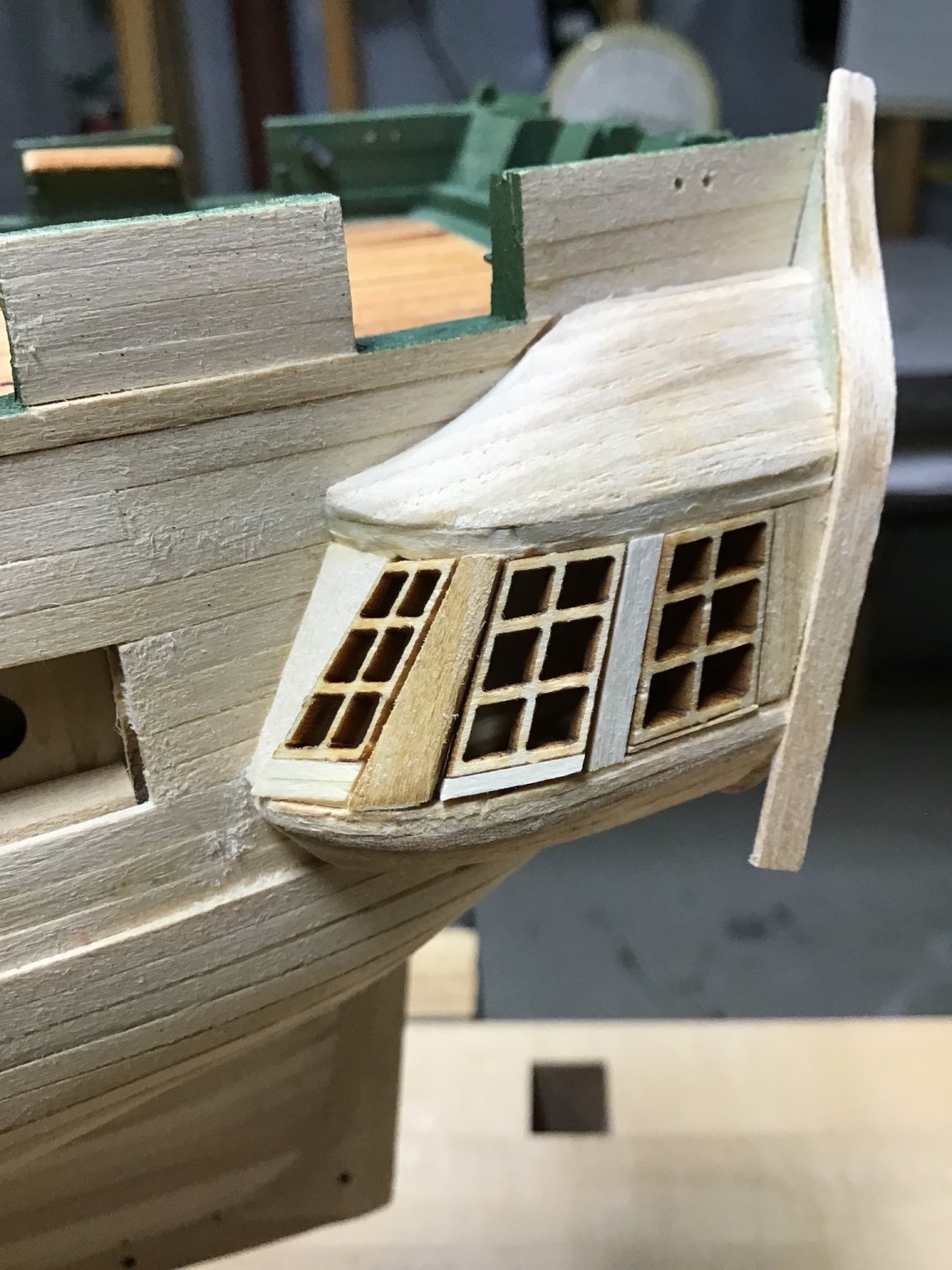
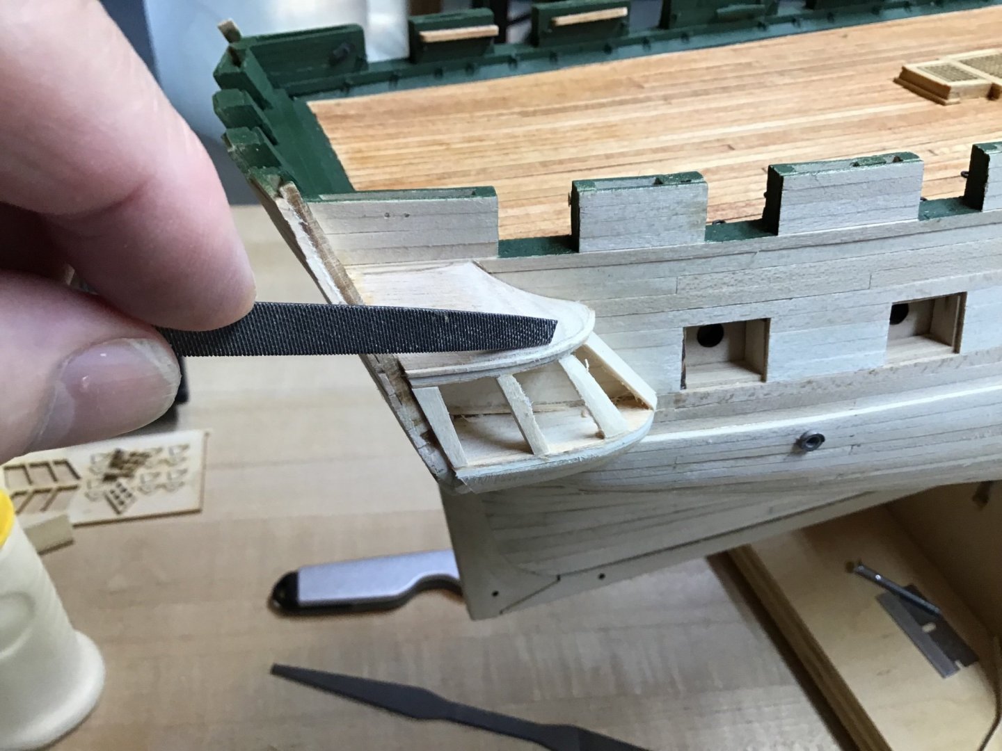
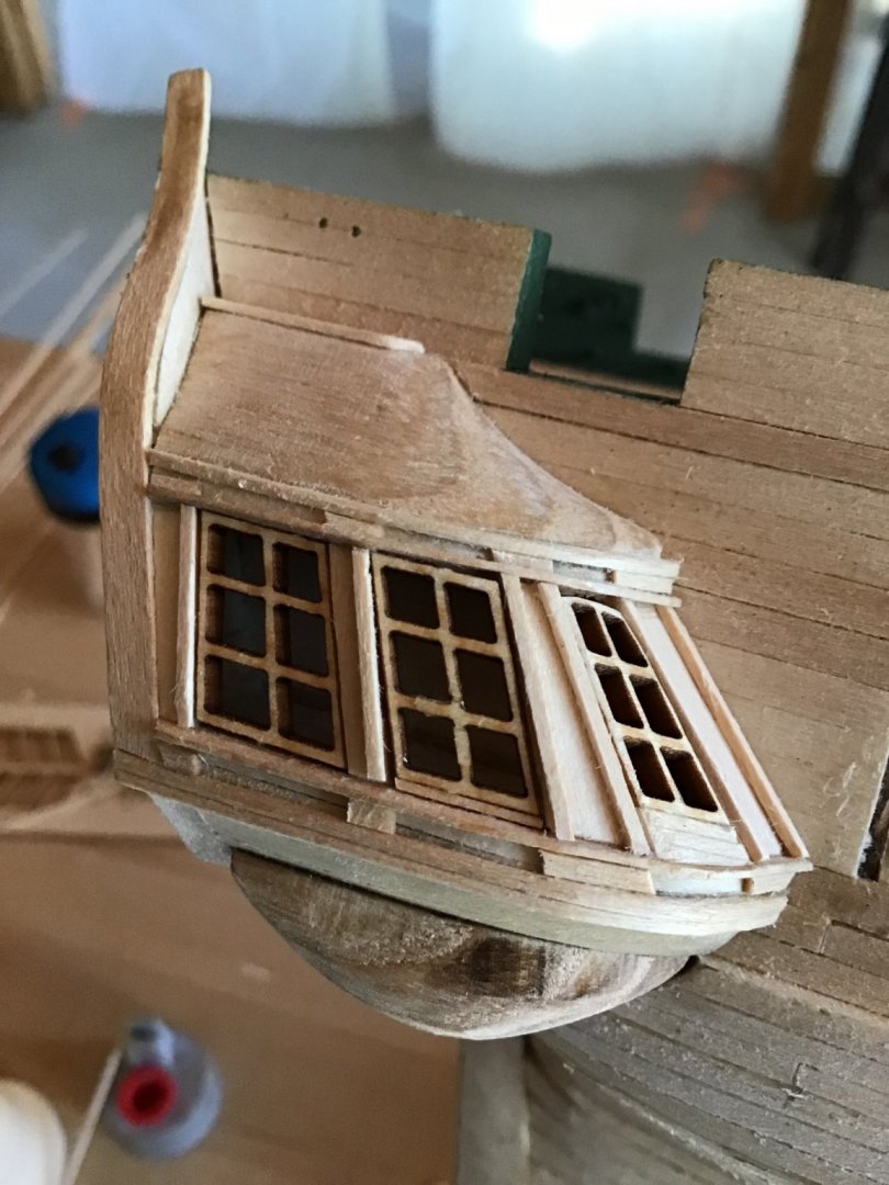
Trimming the Galleries After the rough, the next step is to trim the galleries. The horizontal trim, 1/32” square, was glued in stages, first picture shows the forward end of the piece glued, this was left to dry completely before proceeding aft. Take care to make sure the trim is straight, it tends to wave. I used a half round file to blend the roof block with the trim - picture 2. Pictures 3 and 4 show the vertical trim pieces in place, and there are little tab pieces between the horizontal trim representing a base and capital. Aware that the plan calls for 2 vertical trim pieces on each vertical stile, the piece between the windows, but two pieces looked a little crowded for me. Next time I’ll try to see if I can mill 1/64” square stock. Overall this is delicate detailed work. The forward and middle window top corners are sanded down to create the curve. The windows are brittle, and easy to chip. Broke the bottom off one and had to glue it together again. Slightly file and sand both the windows and the frames to get the the windows to sit square with an even gap all around. Still some work to do on that. At this point there maybe little gaps, say between the horizontal and vertical trim that will be bridged with sealer, and primer. Right now my thought is using a lite coat of Minwax Ipswich Pine, then prime with Vallejo acrylic primer. Need to test that. Next is making the bottom fairing piece - notice the rough piece in the pictures.


-
thanks, just decided to do it my own way....🤔
-
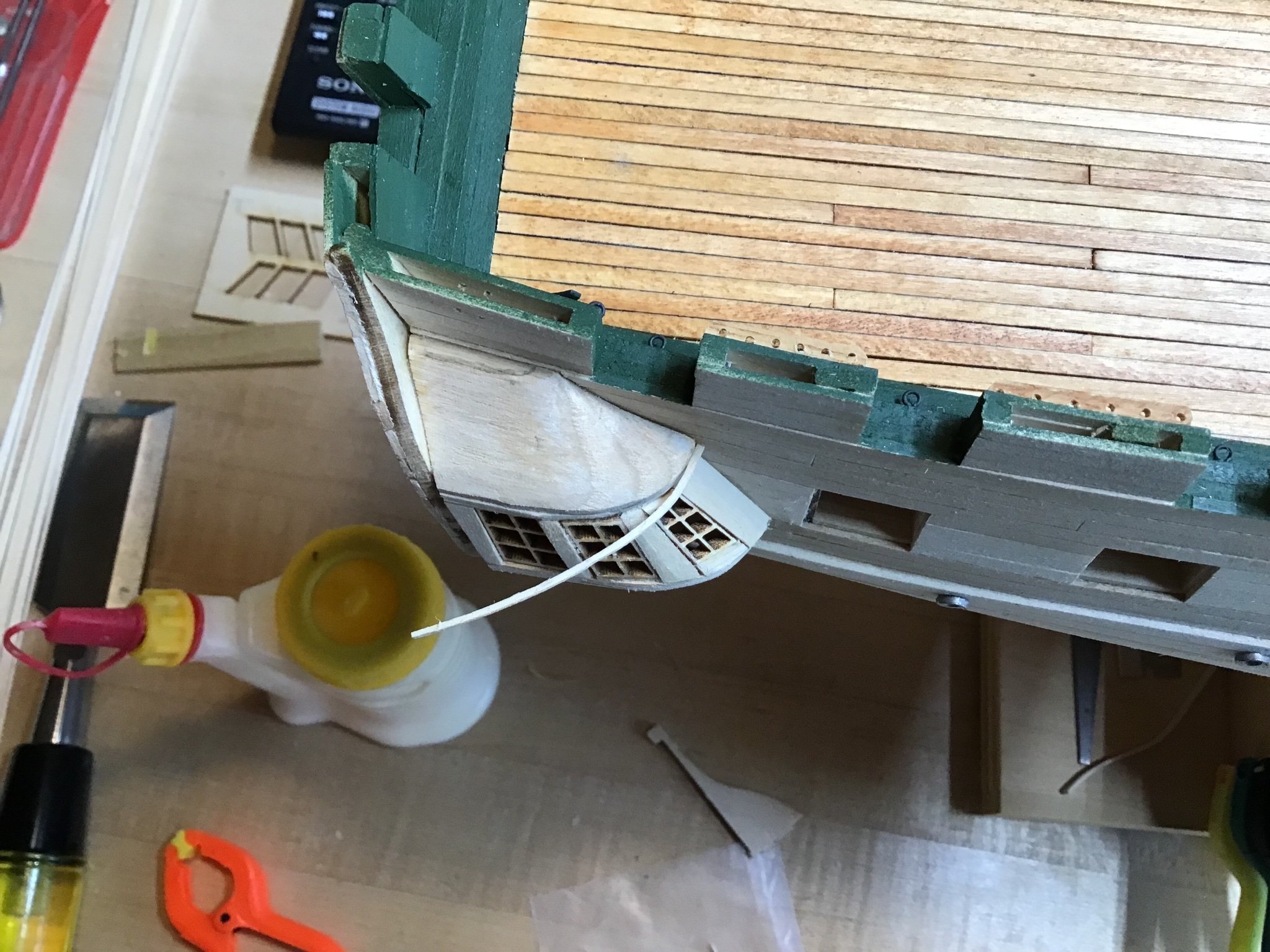
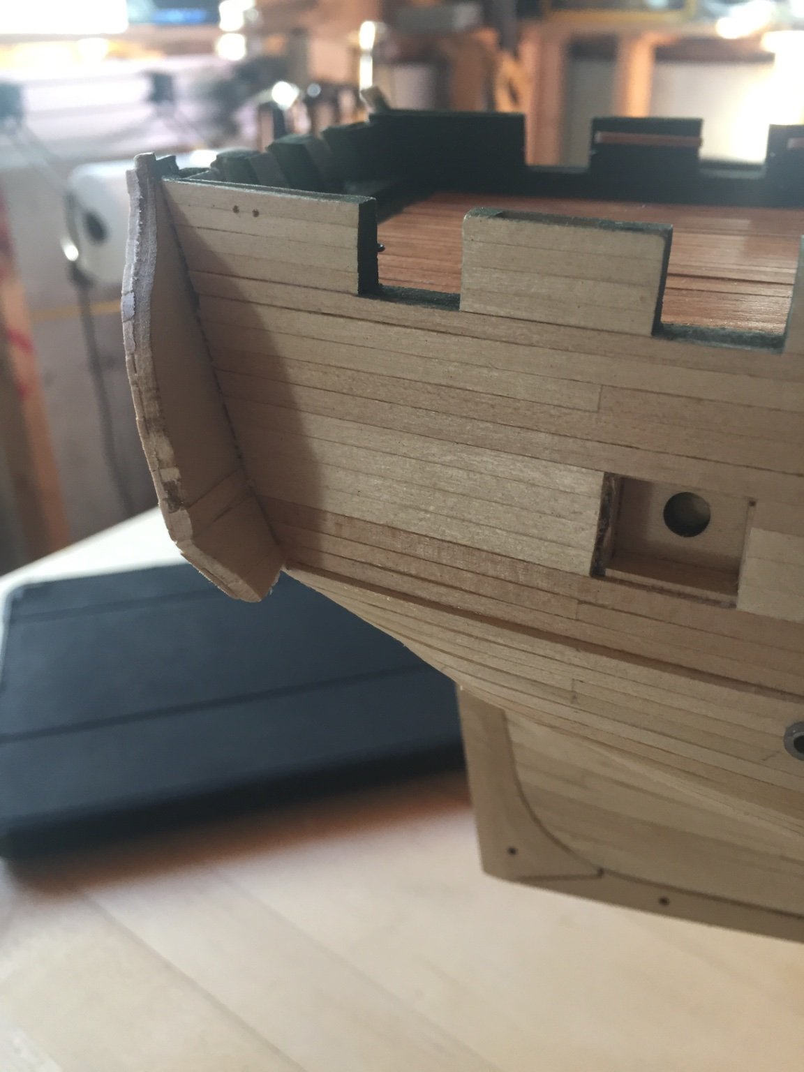
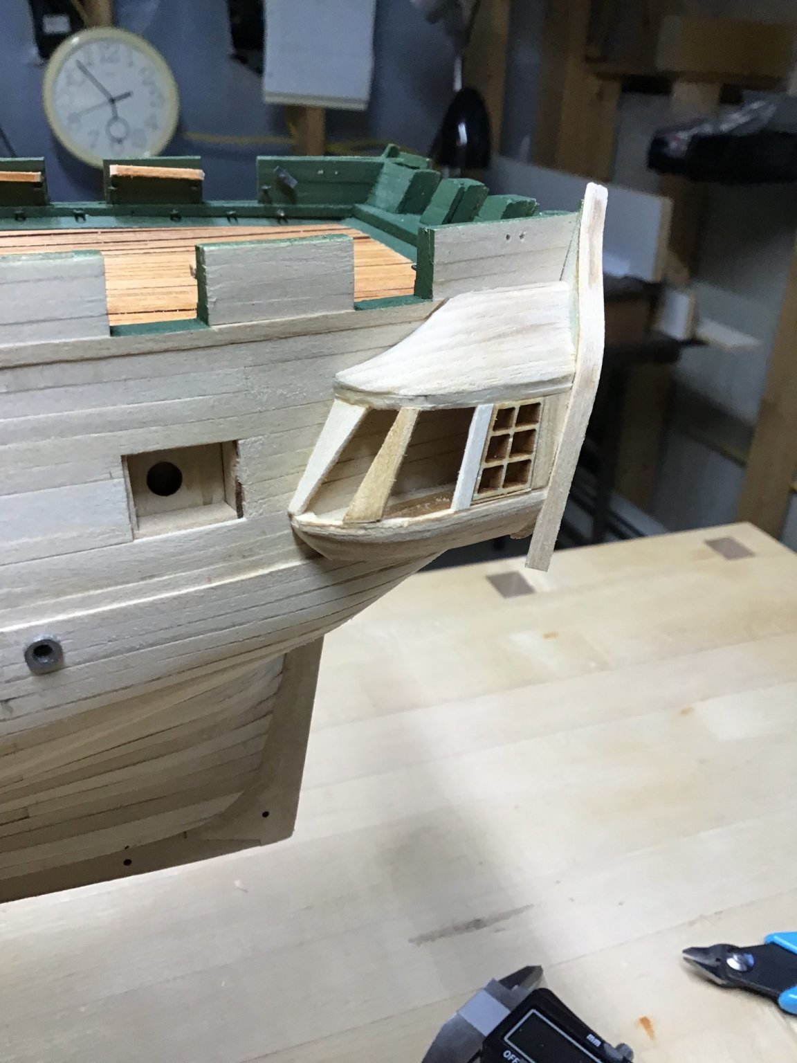
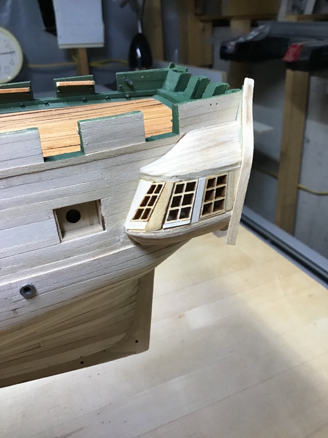
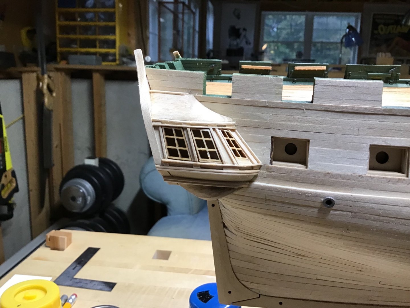
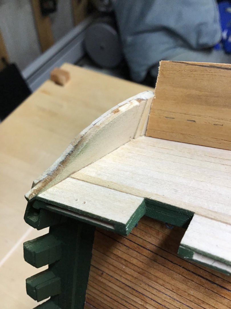
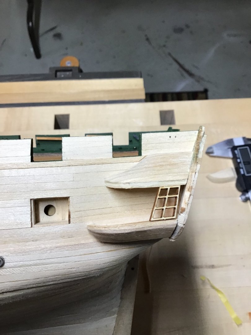
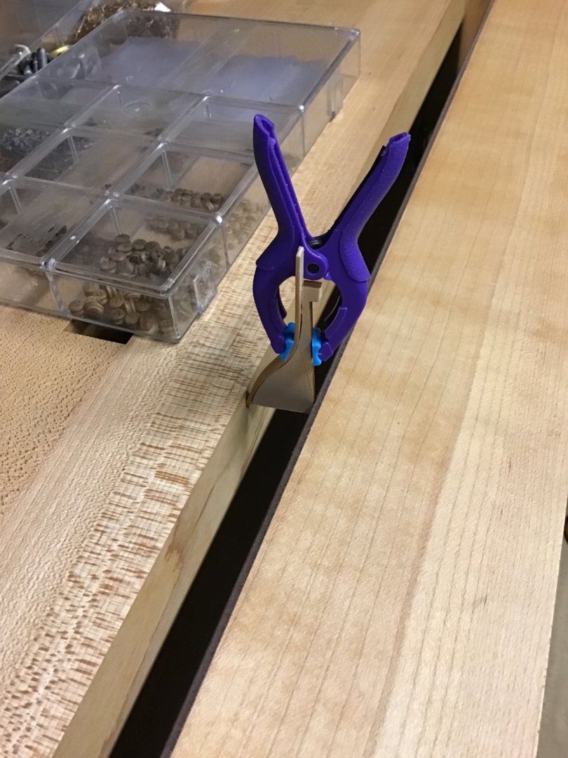
Quarter Gallery- Part 1 This part shows the rough work associated with the base, windows, and roof. Part 2 will cover the lower fairing block and trim. Made the gallery base and roof out of hickory. Hardwood will hold on edge better than soft pine. The following shows how the base was made, same methodology for the roof. Started with 1/4” stock (7/16” for the roof) and ripped the outboard angle. Picture 1. The angle was taken from the base template on the plan. Then used the tilt table and miter gauge to cut the compound angle in the aft end to fit the angle of the gallery wing. Picture 2. Byrnes saw makes what could be a difficult task, trivial. So easy to dial in the angles. Pictures 3 and 4 show the fit of the lower piece against the gallery wing from the bottom and top. The templates were used to mark up the stock. Picture 5 shows sanding along the top line. A file was used to smooth the outboard bevel on the lower piece, and the roof contour. The templates were essential to get the correct shape. Next the top and bottom blocks were glued to the hull. Picture 6. The aft window was used as a spacer. Note both the base and the roof have the sill and a thin trim piece installed. Finally the window openings were framed - starting at the aft end and moving forward. Picture 7. Notice the frame pieces are extra thick and sit proud. Pictures 8 and 9. They will be shaped to match the curvature of the base/roof. The windows are a press fit and are removable for painting. The edges will be sanded to establish a curve. Notice the window sill is built up, so the window sills stair step at the bottom and are aligned along the top. The last picture shows forming the cap strip with a piece from the billet and a clamp.


-
Congrats SeaHoss!
-
Now that’s a great suggestion about the blade, thank you very much for reminding me! Regarding the trim/painting. One possibility is painting the trim first, white, then masking and applying black. Light color first, then dark. To save time and tape, going to paint black first with an Iwata RG-3 mini spray gun, then paint the trim white, with a brush. Another thought is the white over black will diminish the “whiteness” of the trim, less pop. And only paint the outboard face of the trim. Will checkout your log to see what’s up with the stern galleries….
-
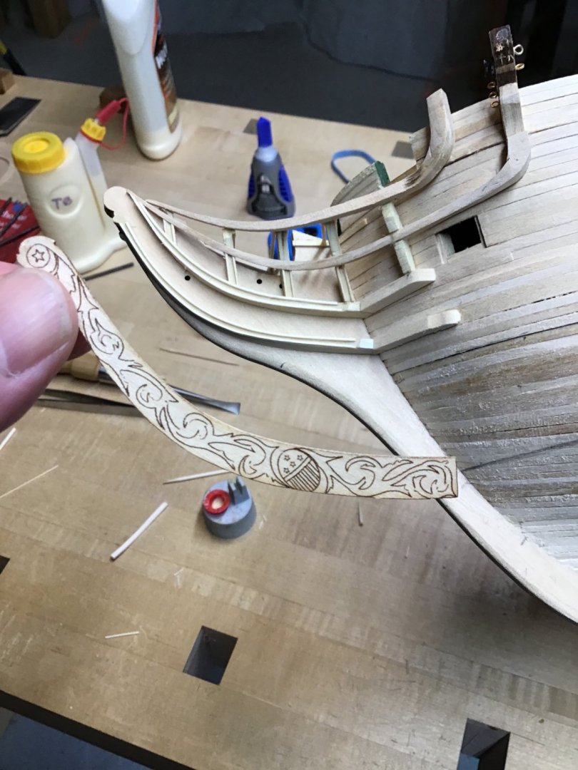
Hi JS, thanks for checking in. The trailboard hasn’t been glued in yet….. Liking the wood trim in a big way, especially how it looks on the timbers. It steam bends easily and glues up nice and quick. Problem is, only 2 strips in the kit. Having trouble making more with my mini table saws - the blade chews up the wood. It’s available from Bluejacket…..
-
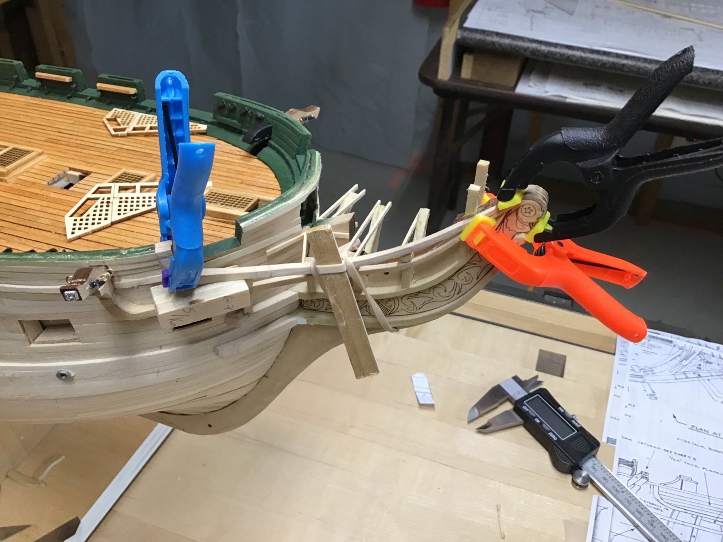
Trim the Head Found 1/32” x 1/32” stock in the kit and decided to use it to trim out cheek knees, rails, and head timbers. First picture shows clamping damp pieces next to the cheeks to bend them to shape. Picture 2 shows some results.

-
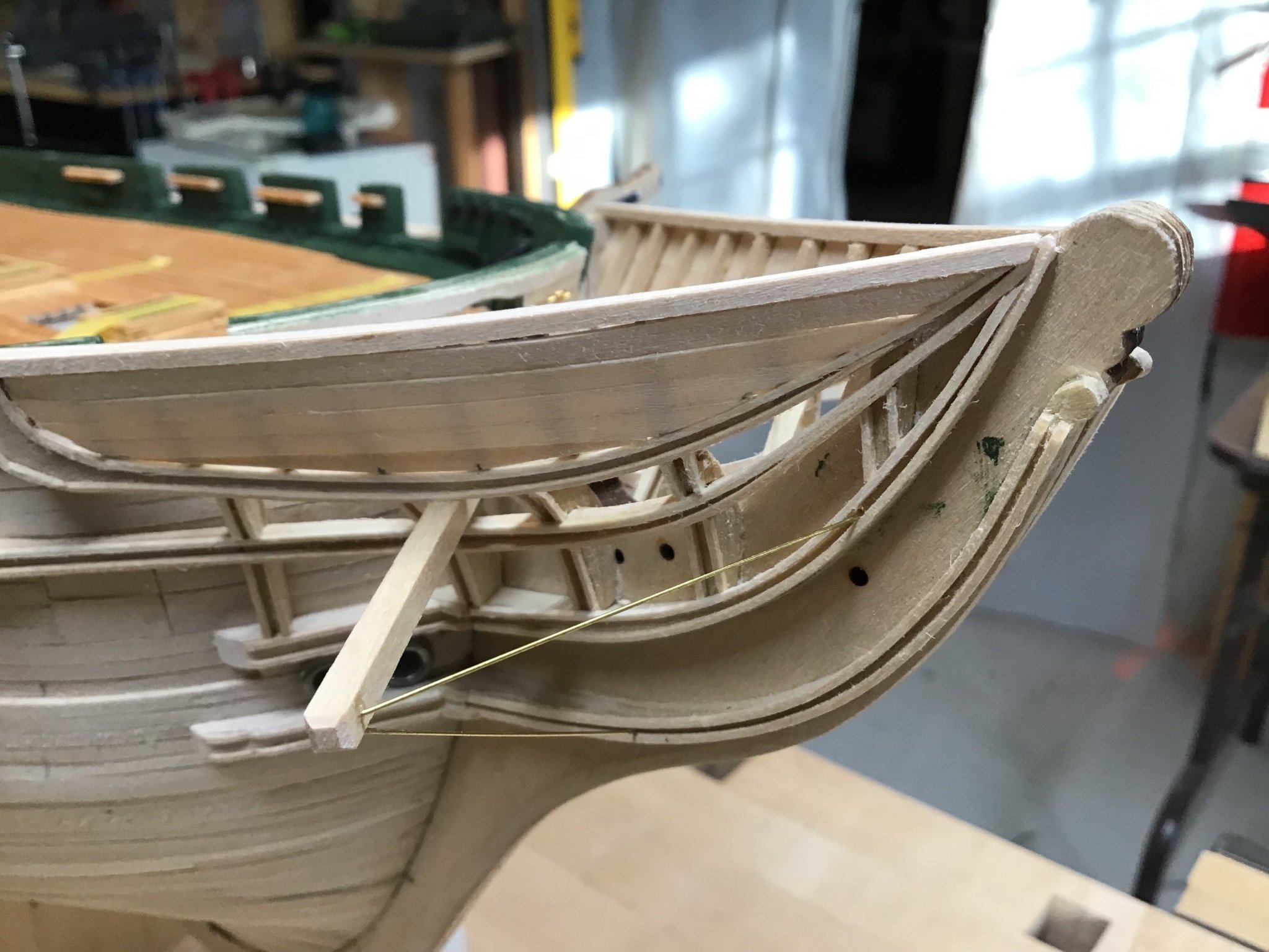
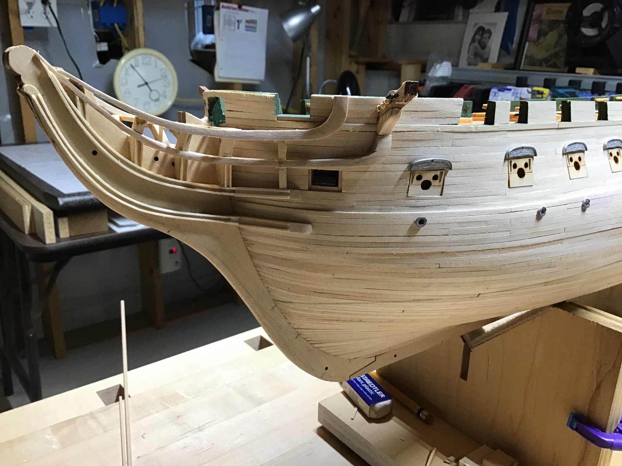
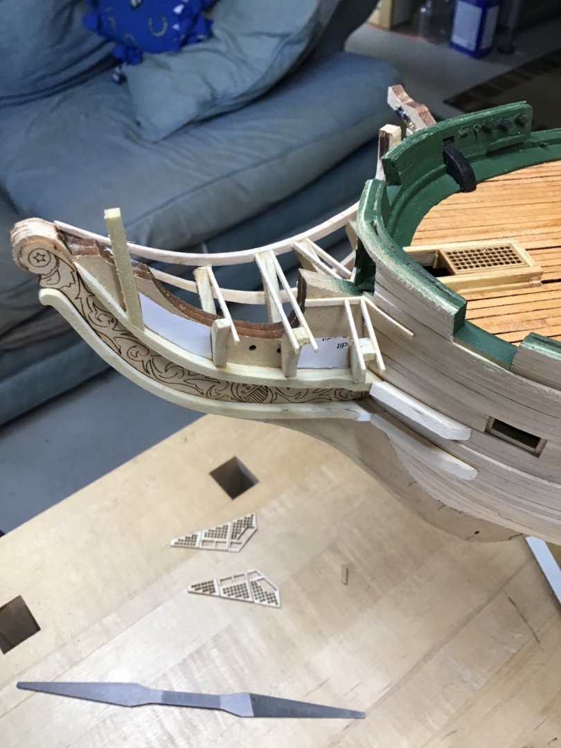
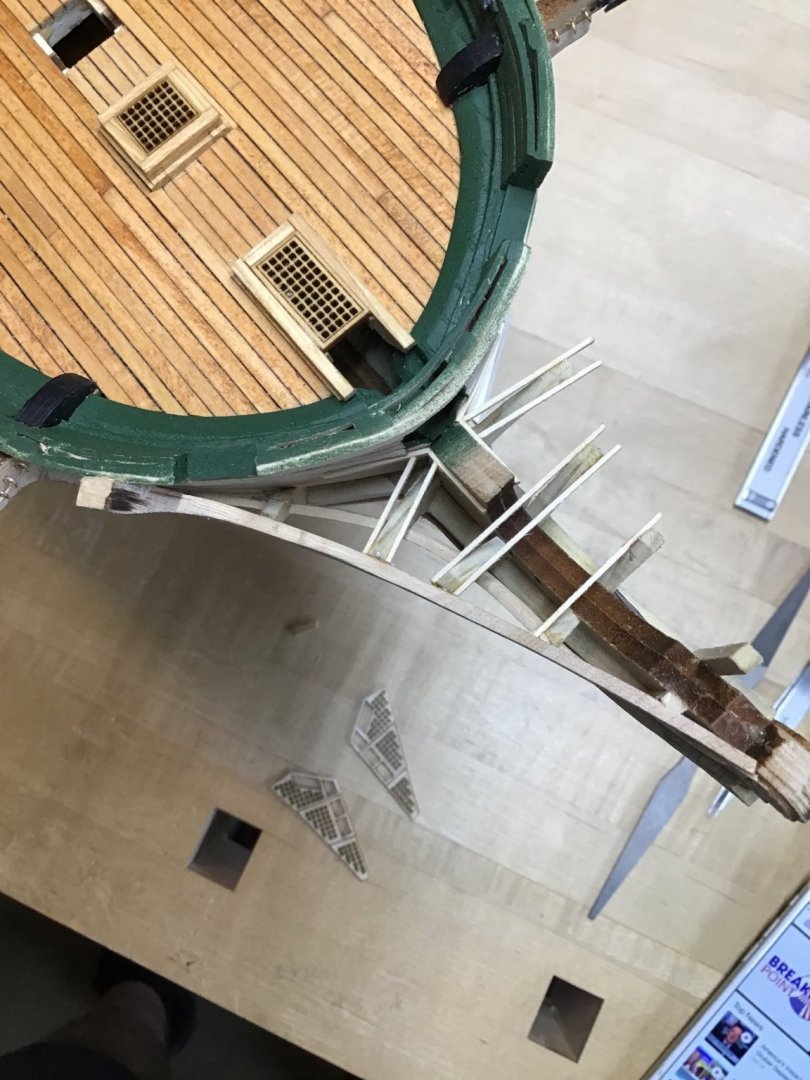
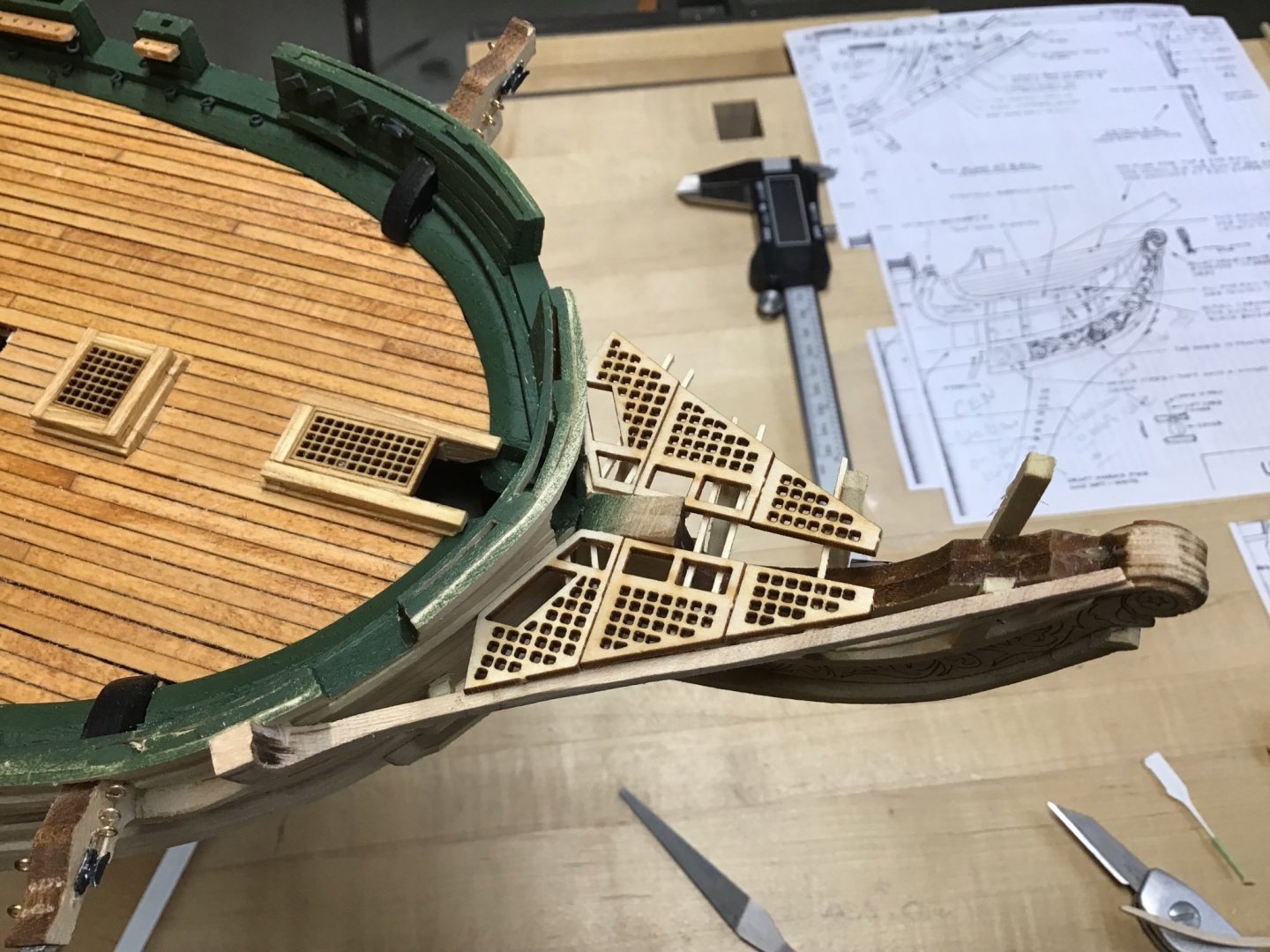
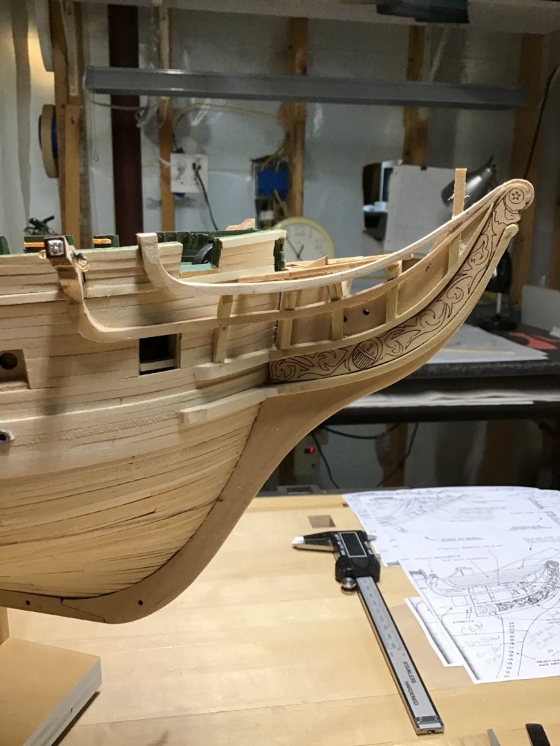
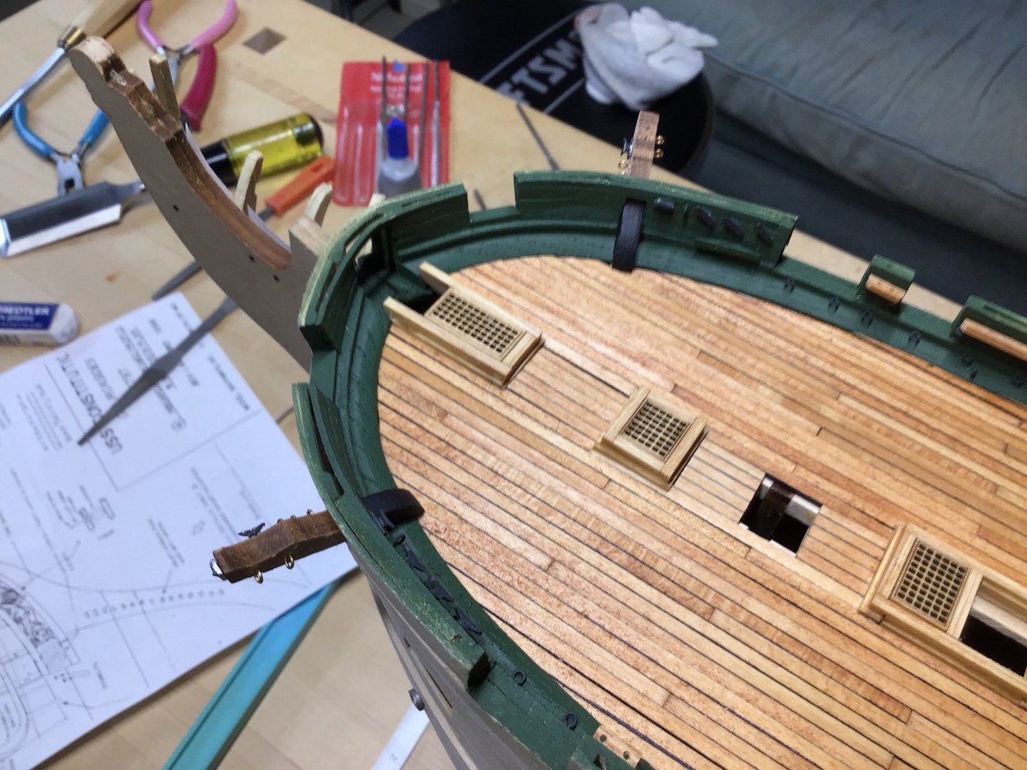
Head Deck Gratings and Second Rail It took me a while studying the plans and the reference books, particularly the Anatomy of the Ship, to understand the sequence to install the Second Rail. Finally understood the deck grating is where to start. The gratings sit on a frame attached to the stem and head timbers, and the rail acts as a fascia board, covering the outboard end of the timbers and the ends of the athwartship grating support beams. Study plan detail 4A to understand this relationship. The deck grating position drives where the beams are located on the timbers. And the location of the beam on the timber drives the final shaping of the timber top. So started by building the grating frames. The frame aft edge is aligned to the bottom of the second strake below the sheer strake. Picture 1 shows the port side frame. Notice the beam ends are a little long and will be trimmed and shaped to fit against the side of the rail. Also notice the rail ends offer additional glue surface area, that will help when glueing up the rail. Picture 2 shows glueing up the rail with ends clamped and a rubber band in the center of the stem looped around the board. Picture 3 shows the rail in place. And picture 4 shows the grating installed. Finally picture 5 shows the side view.
-
Hi Bob, and thank you. Trying to show this in a way that is easy to do and understand. Good luck on your Constitution. -Rich
-
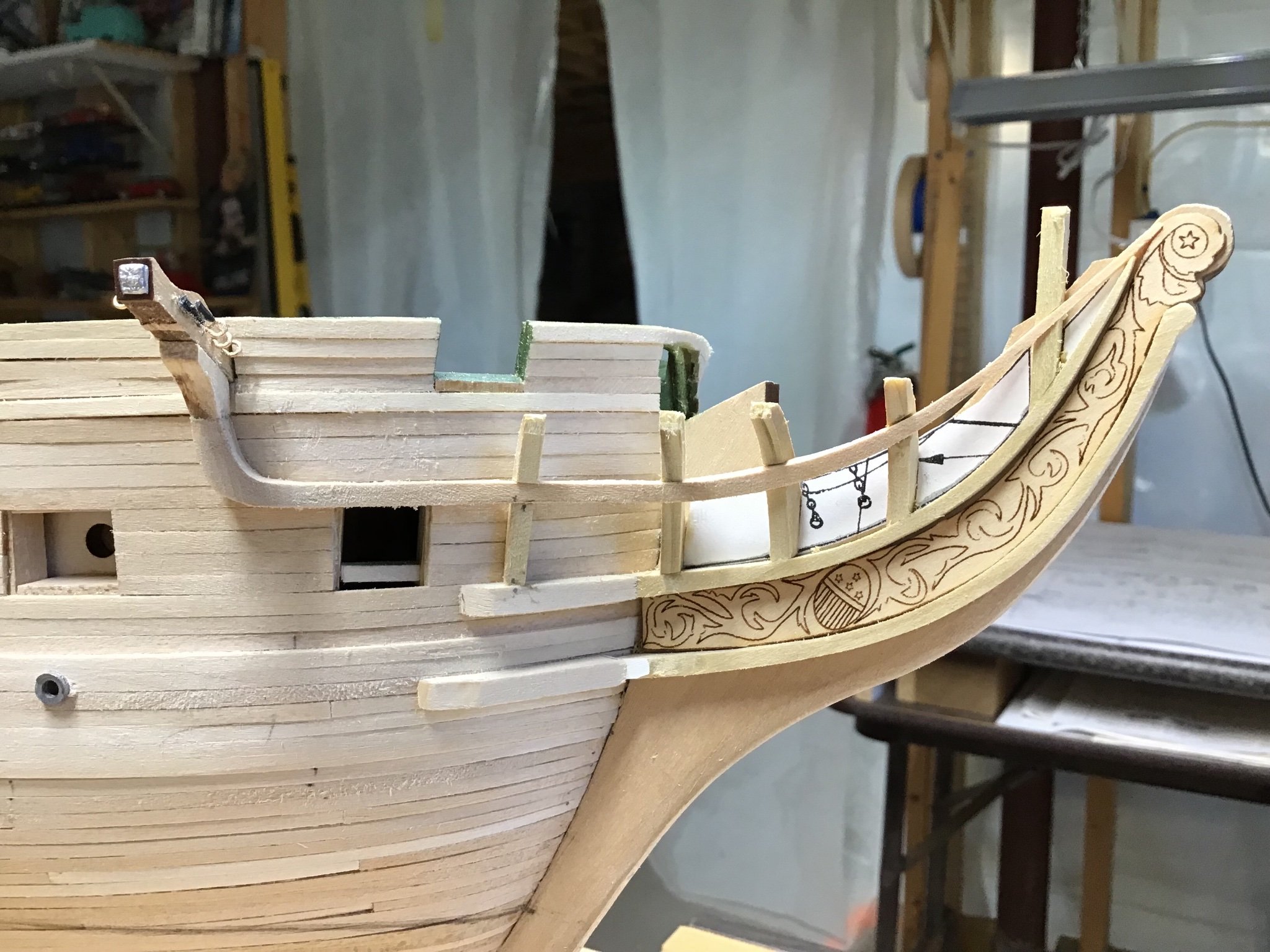
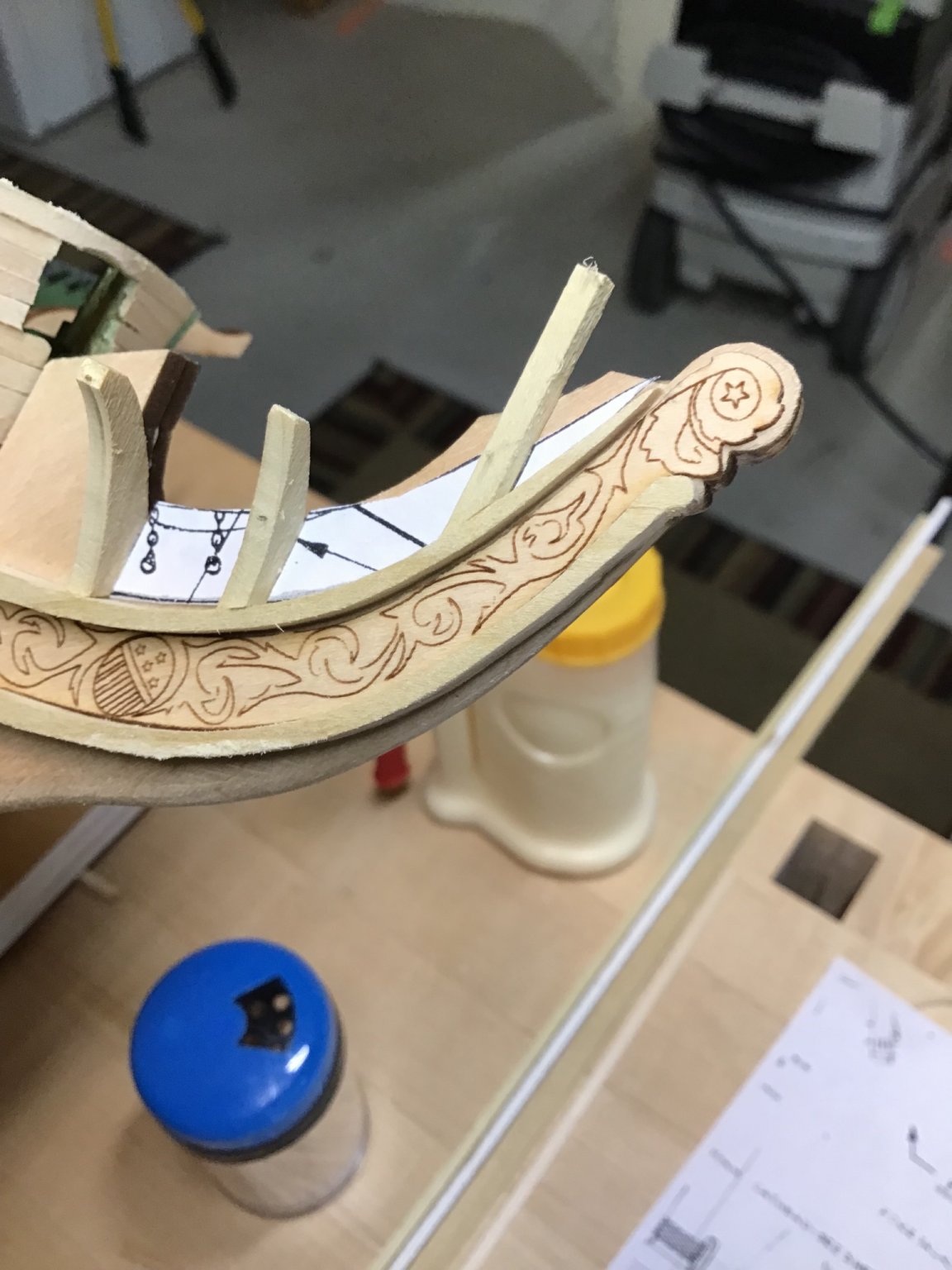
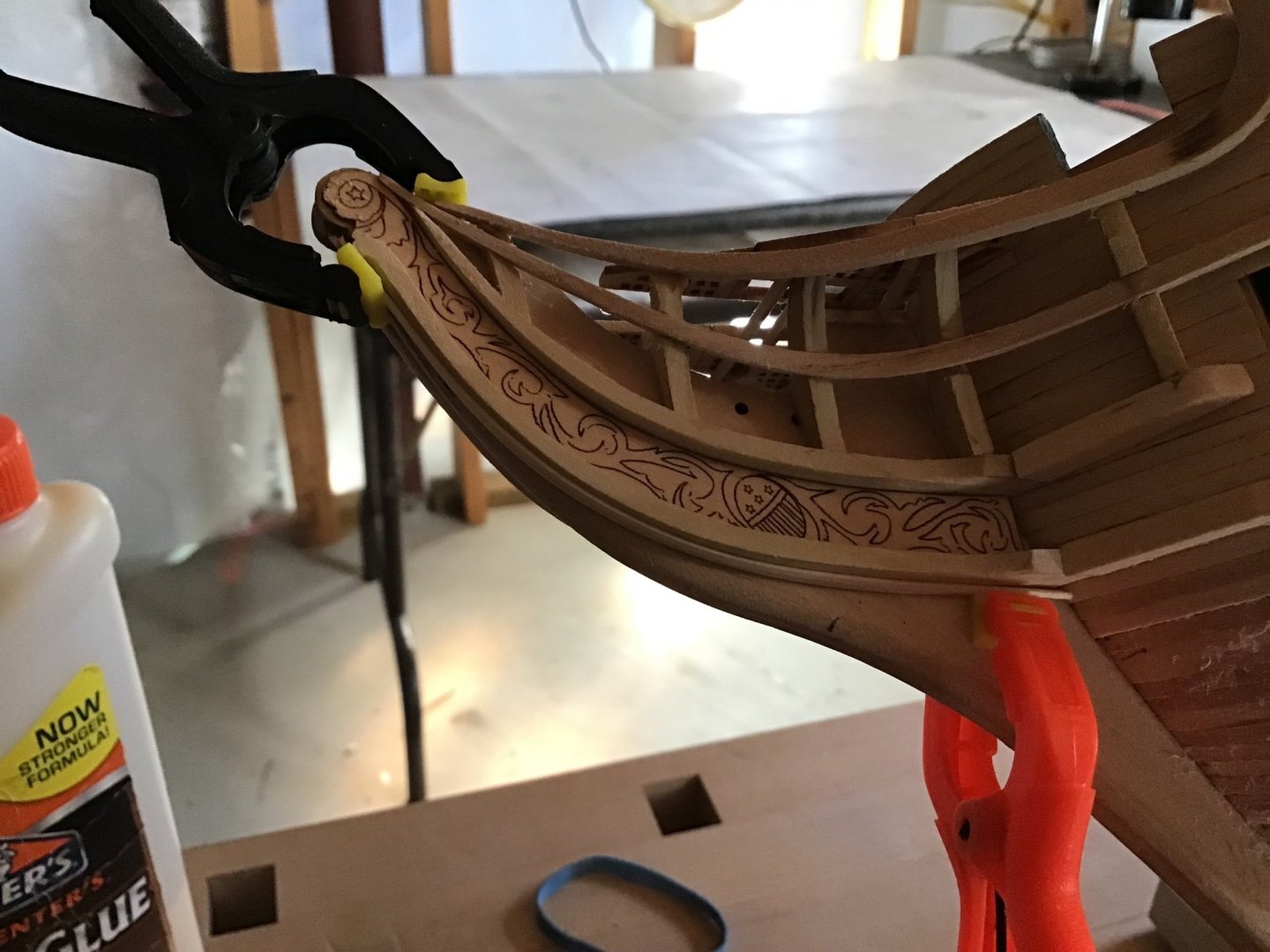
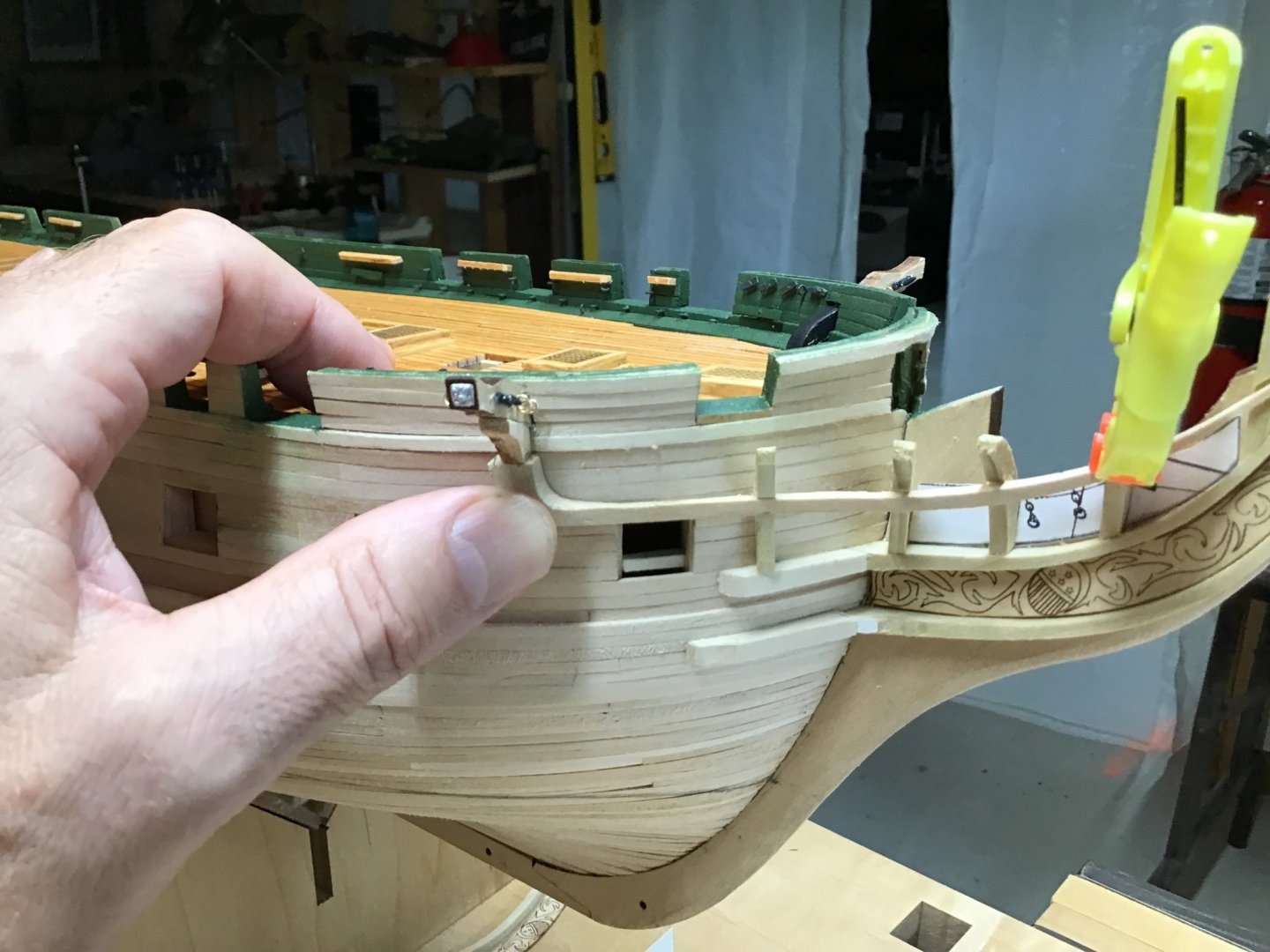
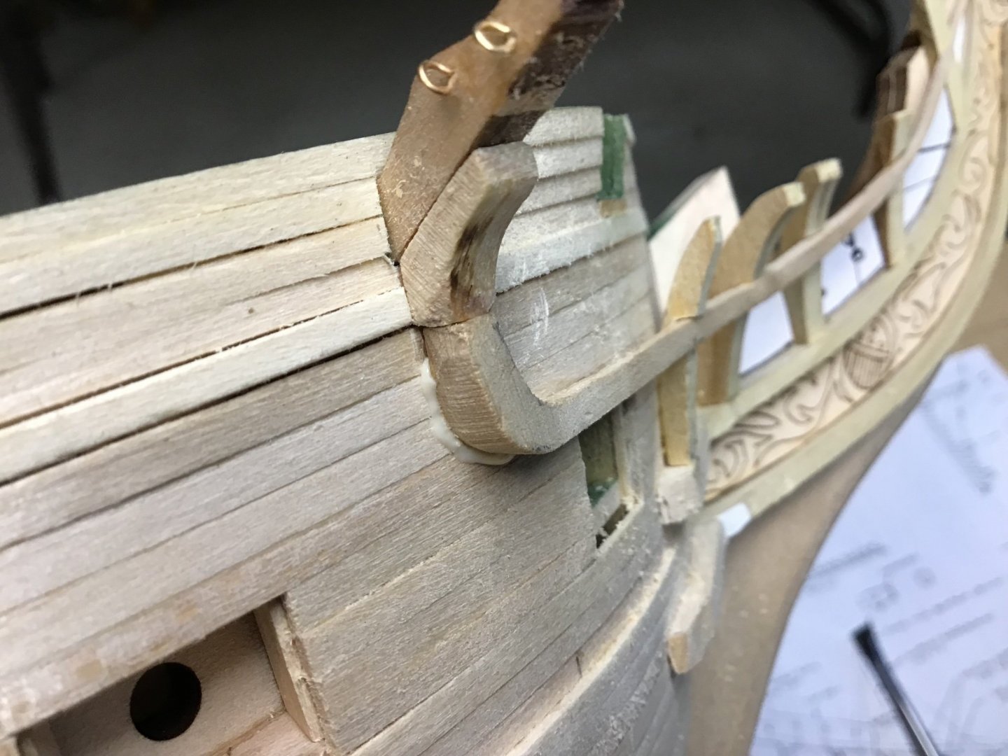
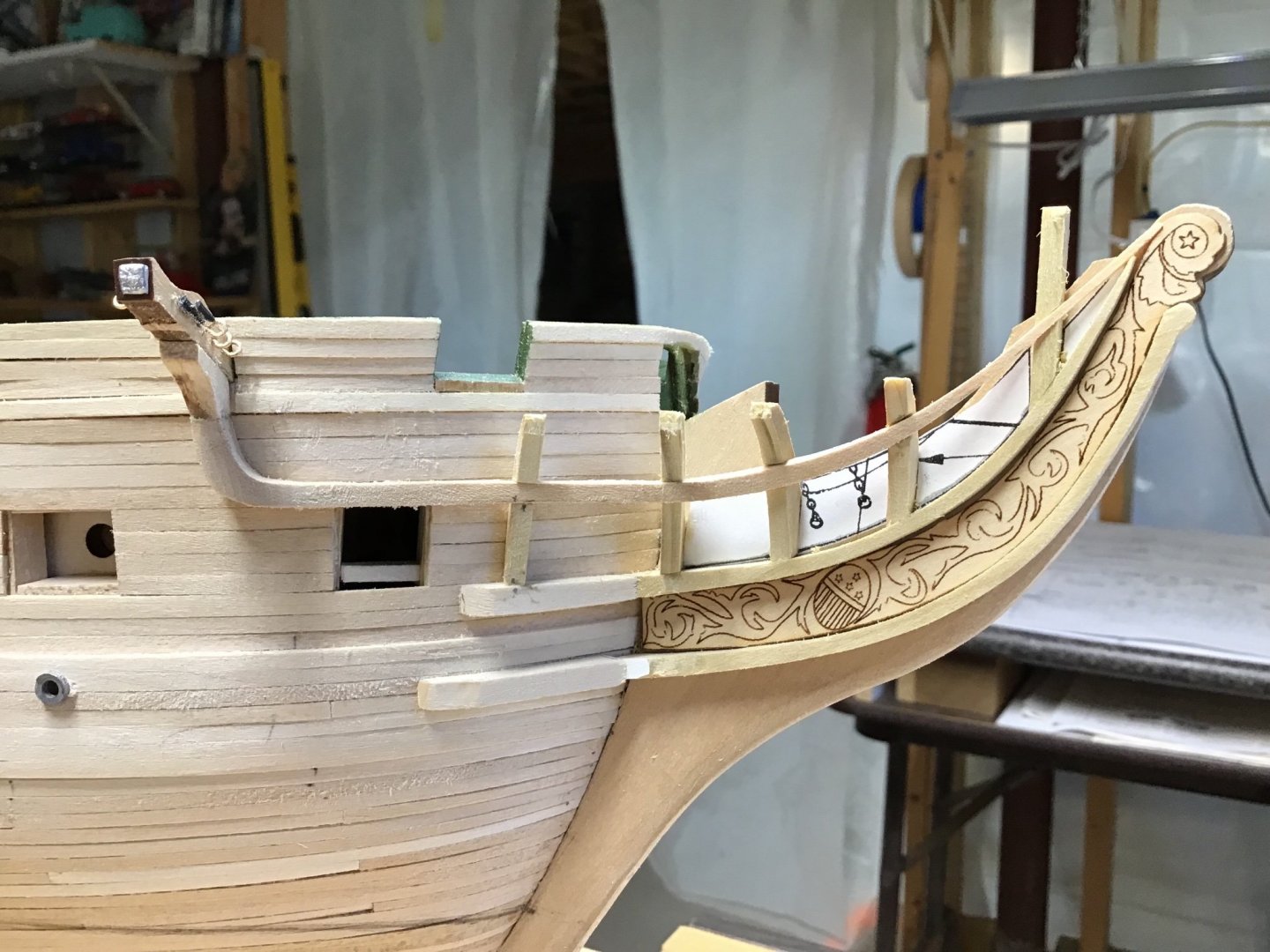
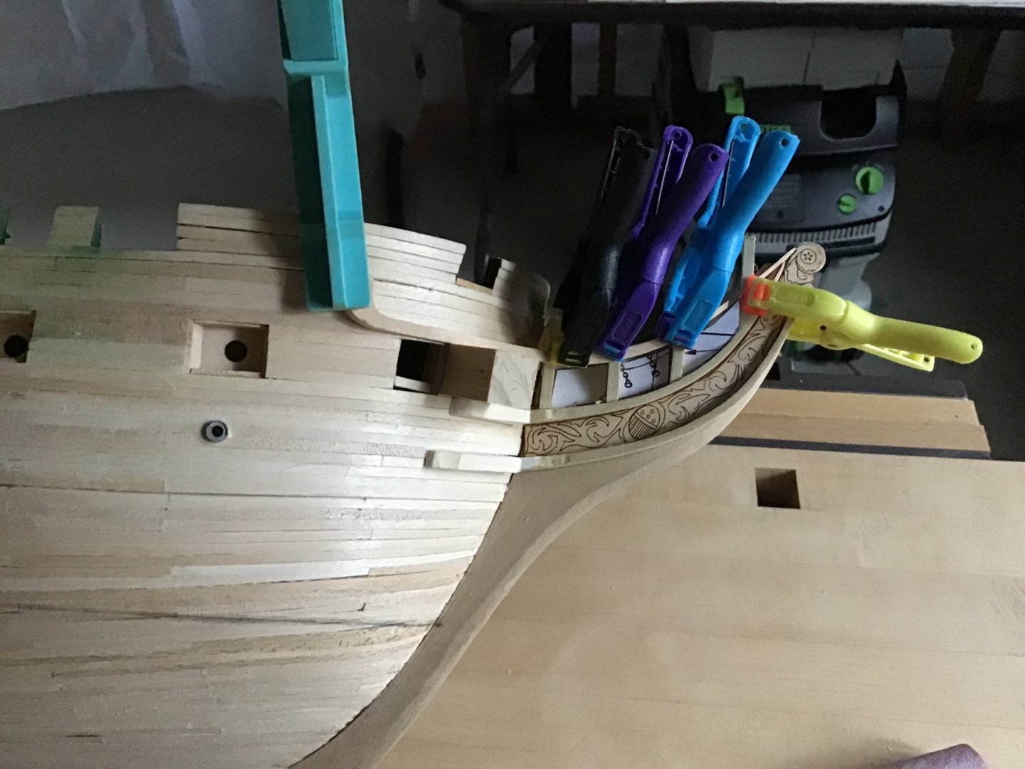
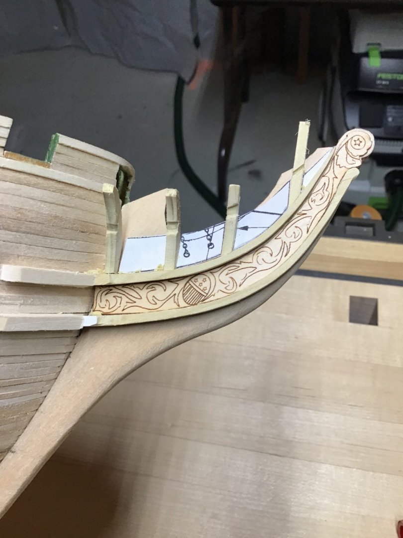
Third Head Rail After much time checking the fit and shaping, forged ahead and began glueing the rail in position, starting with the forward end and working aft. So glued the forward end of the rail to a position just aft of the laser cut scroll work and the first timber, then clamped, and let dry. Repeated 2 timbers at a time. After starting, realized that’s the horn on the aft end was not shaped as much as I wanted but had to go with it. Picture 1. Picture 2 shows glue squeeze out along the rail horn, to get some gap filling. Use a toothpick to remove the excess after a few minutes. I also used a dab of CA to get a quick hold without clamping. Pictures 3 and 4 are views after shaping the cathead support knee and the aft end of the rail, using a cylindrical burr in the Foredom - Picture 5. I think the rail horn needs a bit more material removed along the lower edge, seems a little fat in picture 3.
-
Thanks KLB, this is the first time I’ve built such an elaborate head, the rails are intimidating. I spent a lot of time looking at the plan and the Anatomy of the Ship reference book. Finally came to realize that there are variations in the references so there isn’t a perfect answer to positioning the timbers. It’s been a very iterative process, shaping the rail, committing and installing the timbers, using the rail to mark the timber notches, checking the fit of the rail, and shaping it. Thanks for checking in and stay tuned!
-
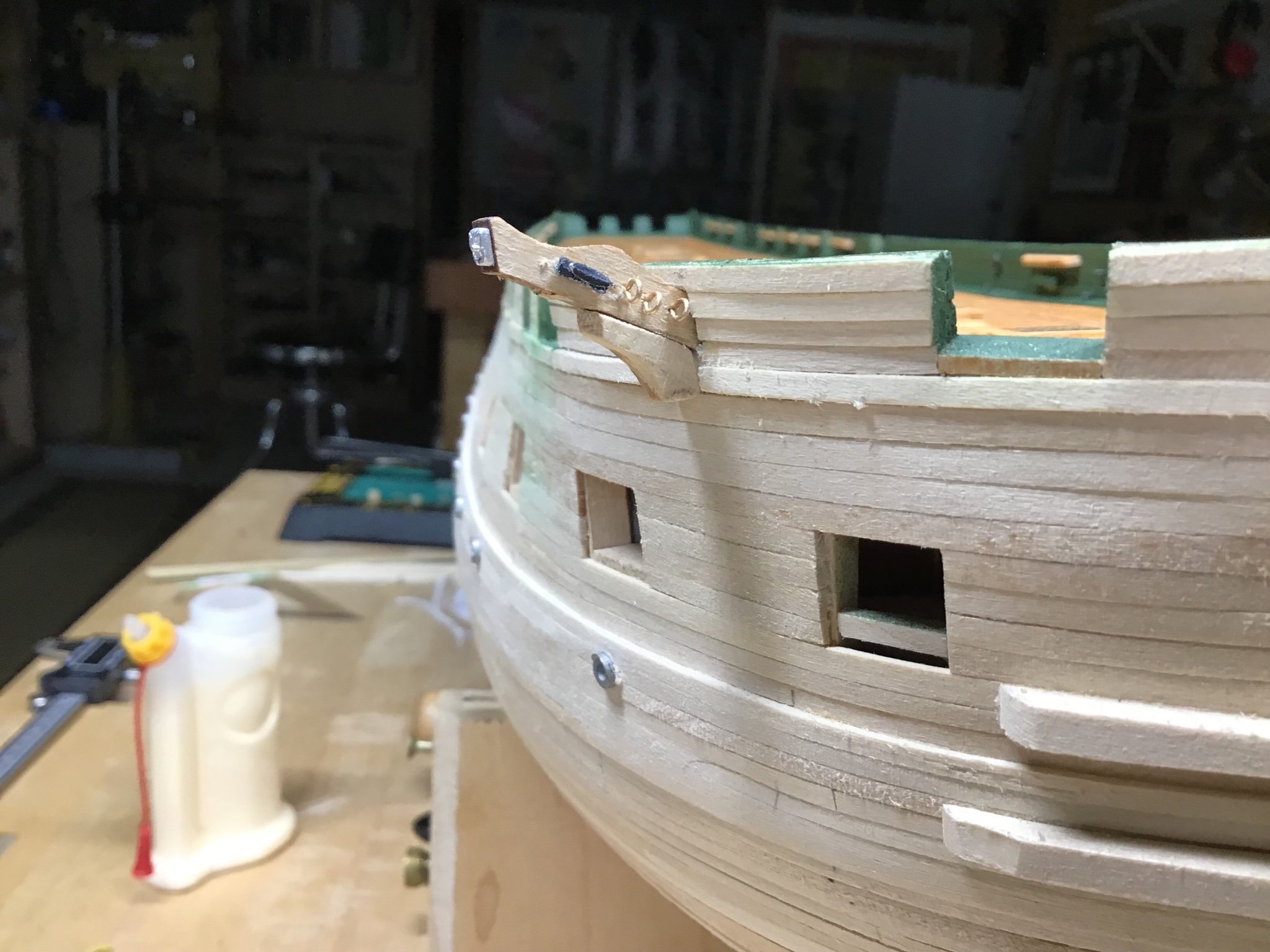
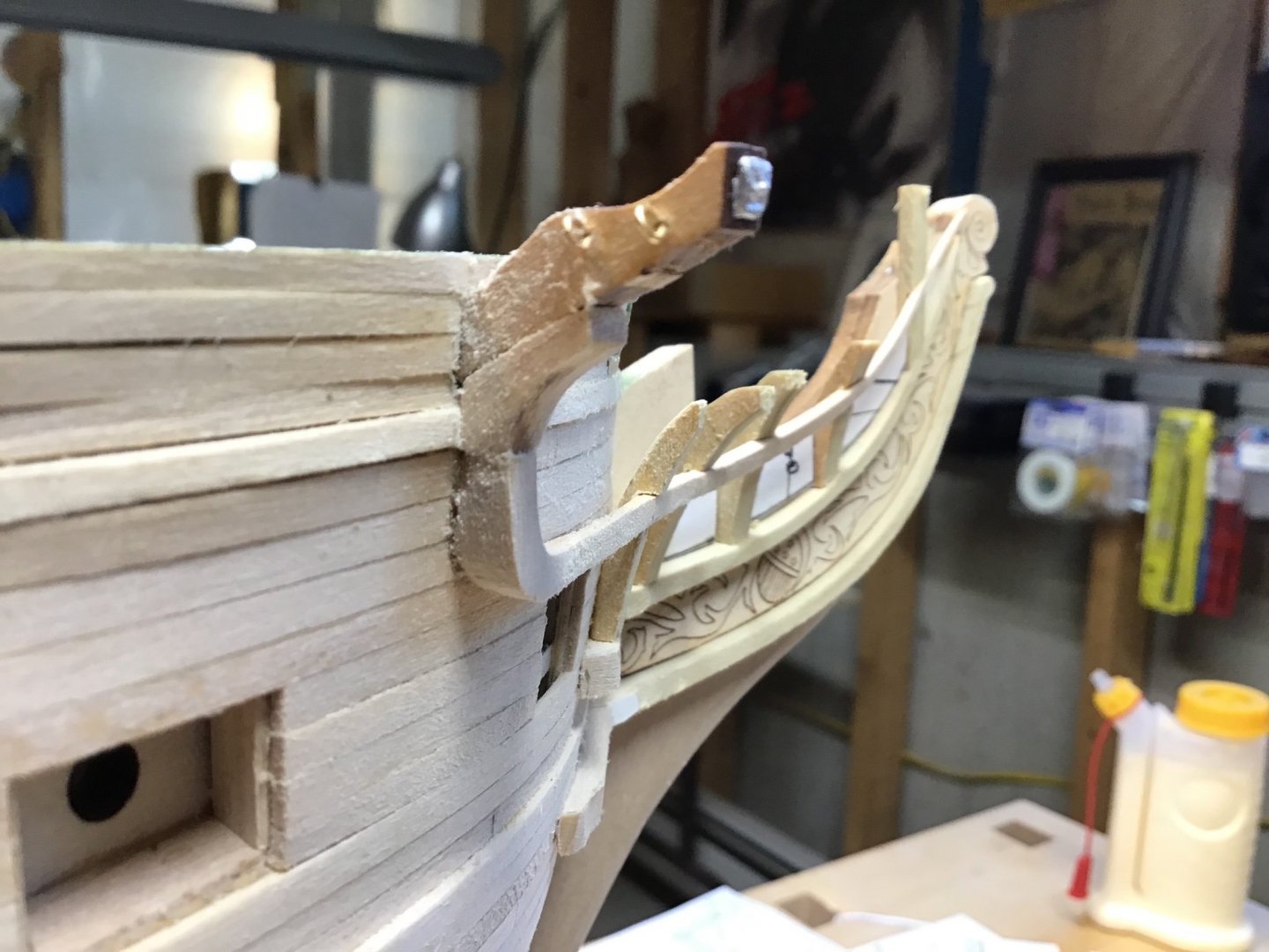
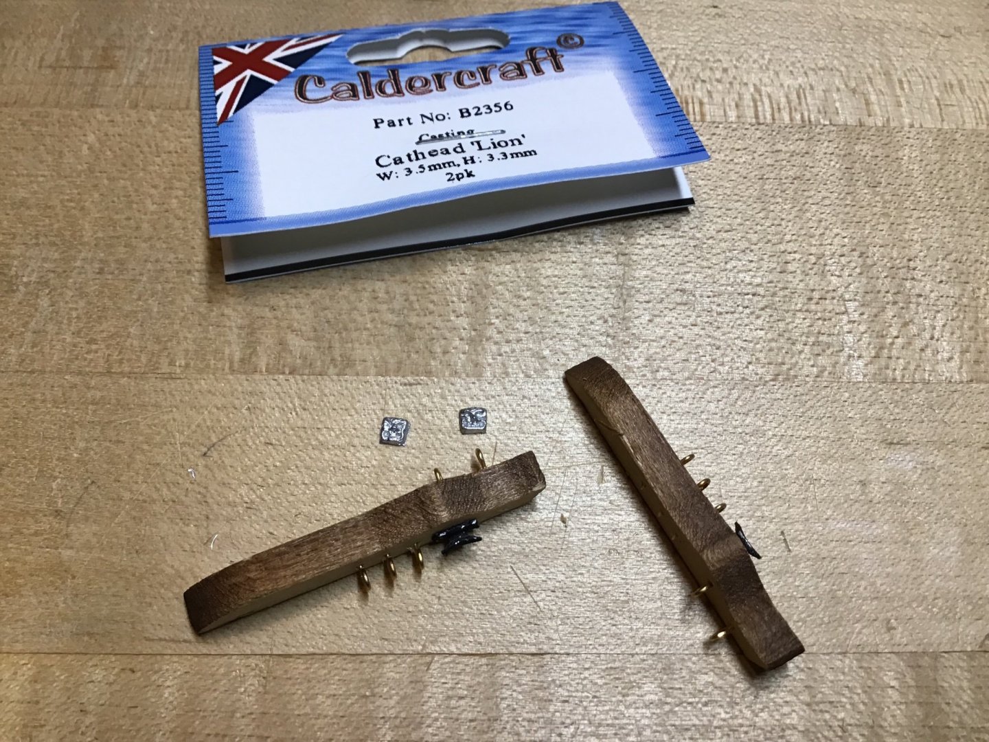
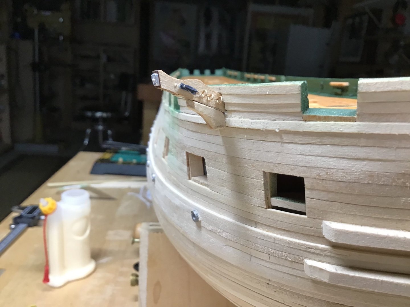
Cathead Attached the hardware on the cathead. Used the Foredom drill press to drill the 1/64” holes for the eyebolts. The cathead face decoration is by Caldercraft purchased from Cornwallmodelboats.co.uk. Note, they are too small, so ordered the larger size. Also drilled 6 holes to simulate the sheaves. Picture 1. Then I painted the inboard ends black and installed. Picture 2. Last I made and installed the support knee with the template on plan sheet 5. Built it a little over wide so it can be blended into the 3rd Rail aft piece. Picture 3.
-
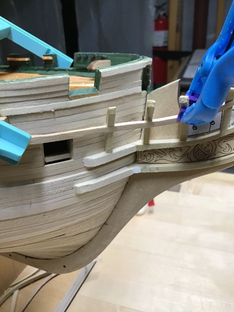
Finishing the Timbers Installed Timbers 4, then clamped the 3rd Head Rail on the timbers to mark the notch locations. Picture 1. Picture 2 shows the notches. Notice that the lower edges of the notch follows the line of the paper templates. Next worked on final shaping of the rail, clamped the rail to the timbers to check the fit, removed and shaped, clamp again, repeat. During this process noticed Timber needed to be moved away from the hull, so broke the glue bond and added a shim. Picture 3. Finally with the rail again clamped in place, determined the location of Timber 5, which needed a bevel on the inboard end.
-
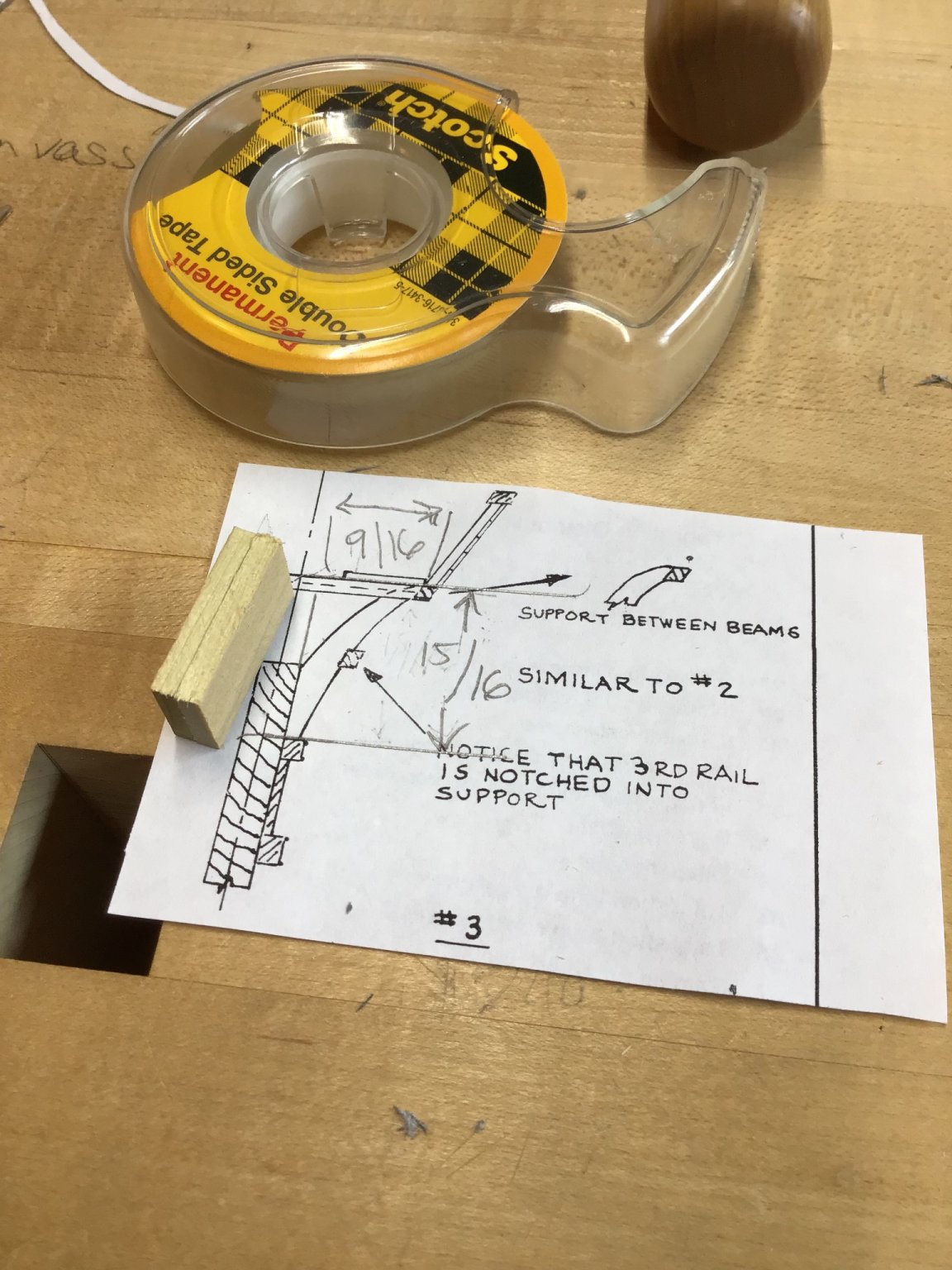
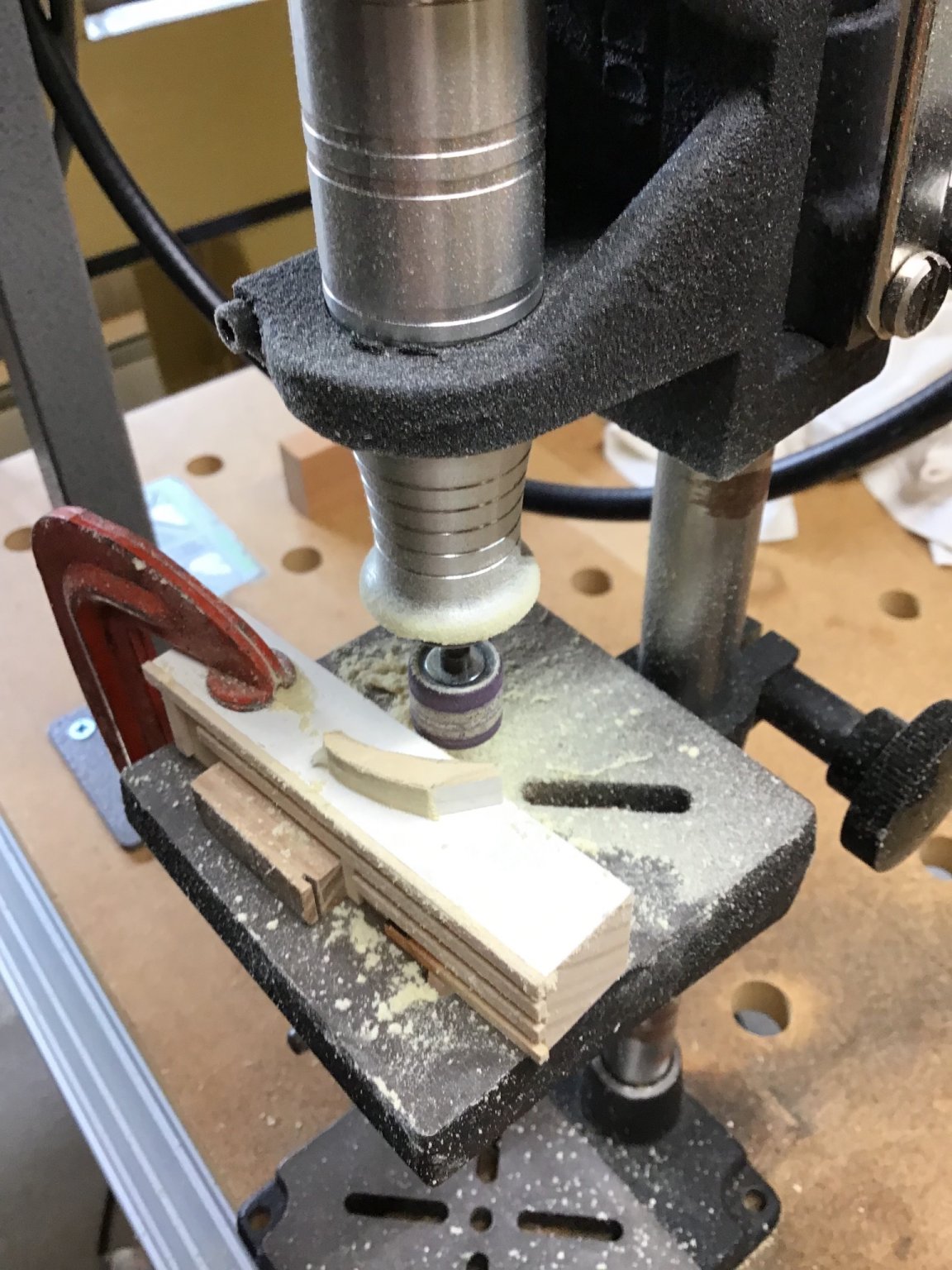
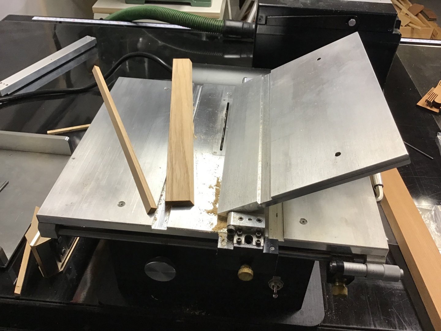
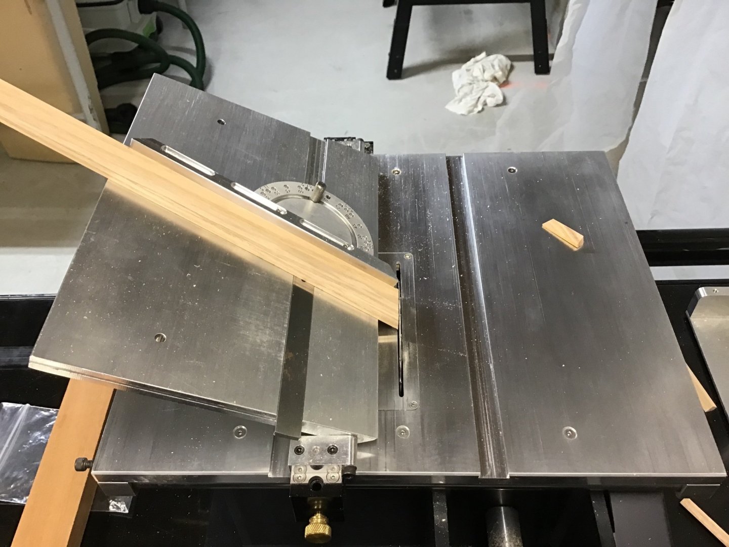
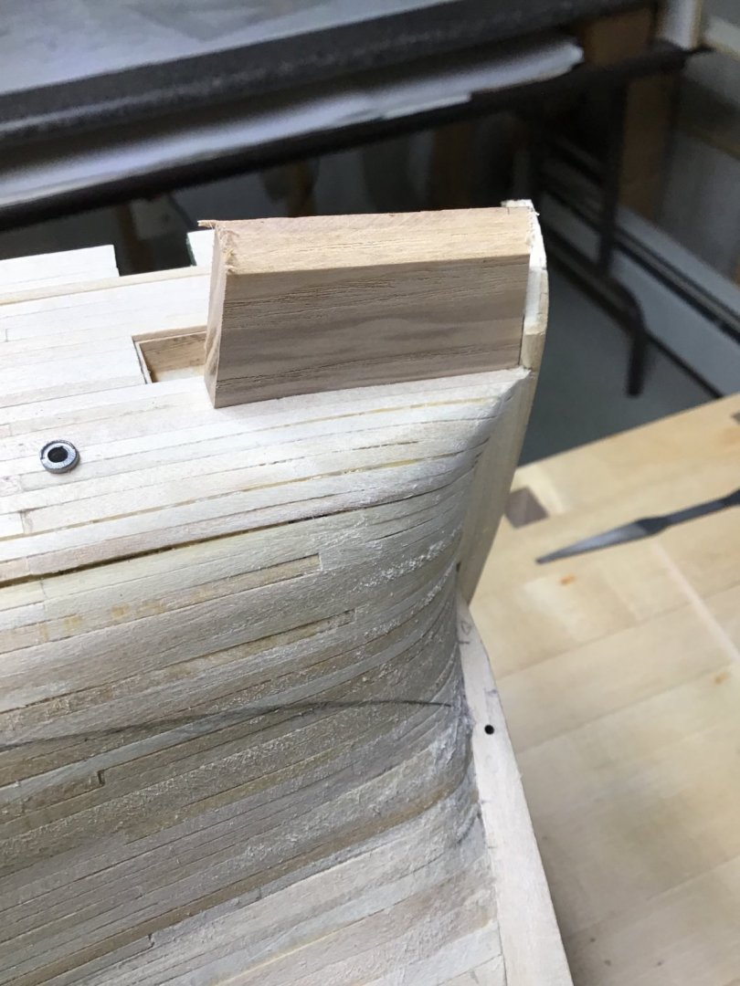
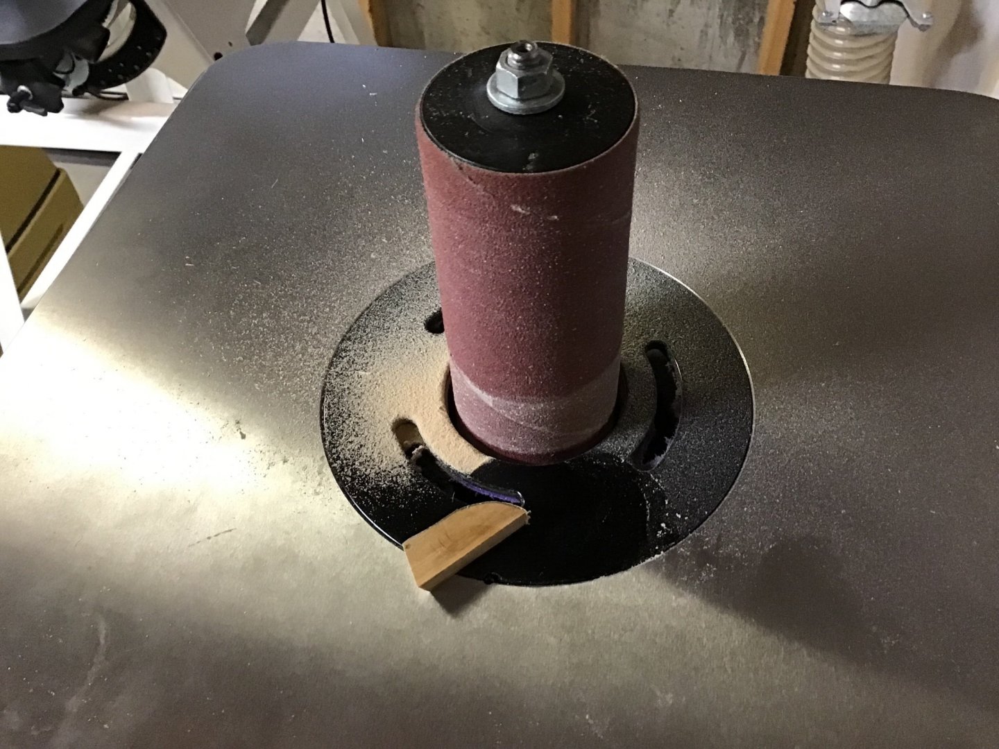
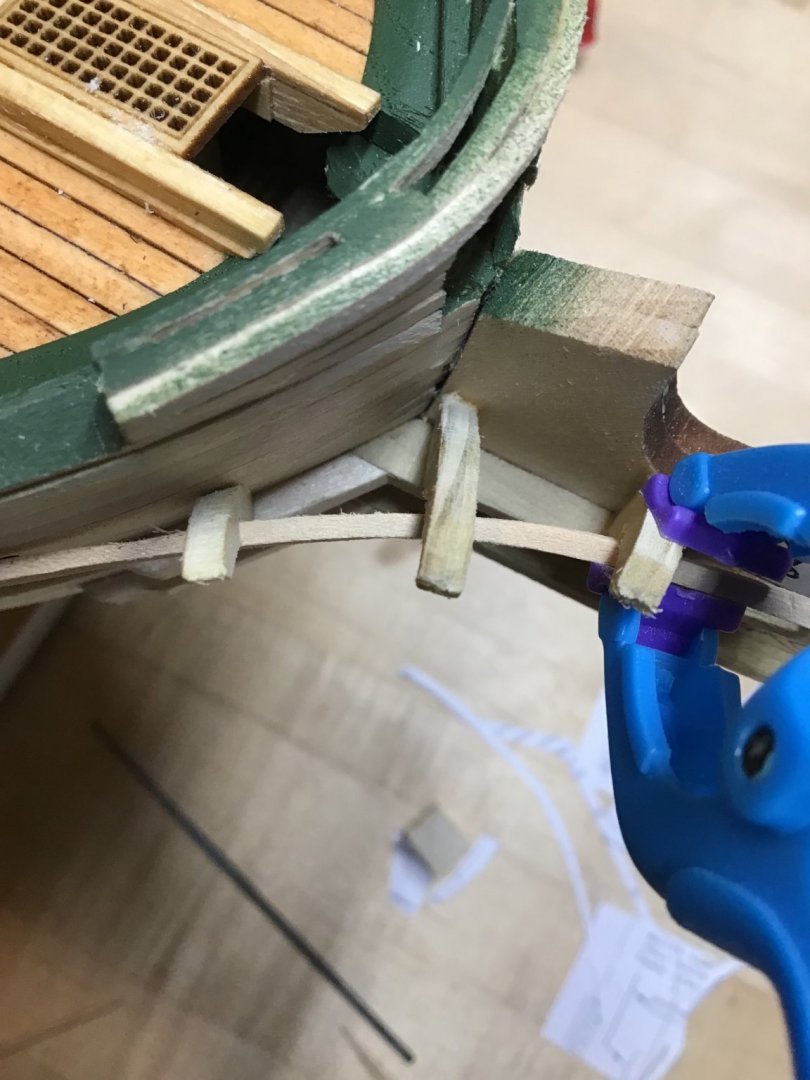
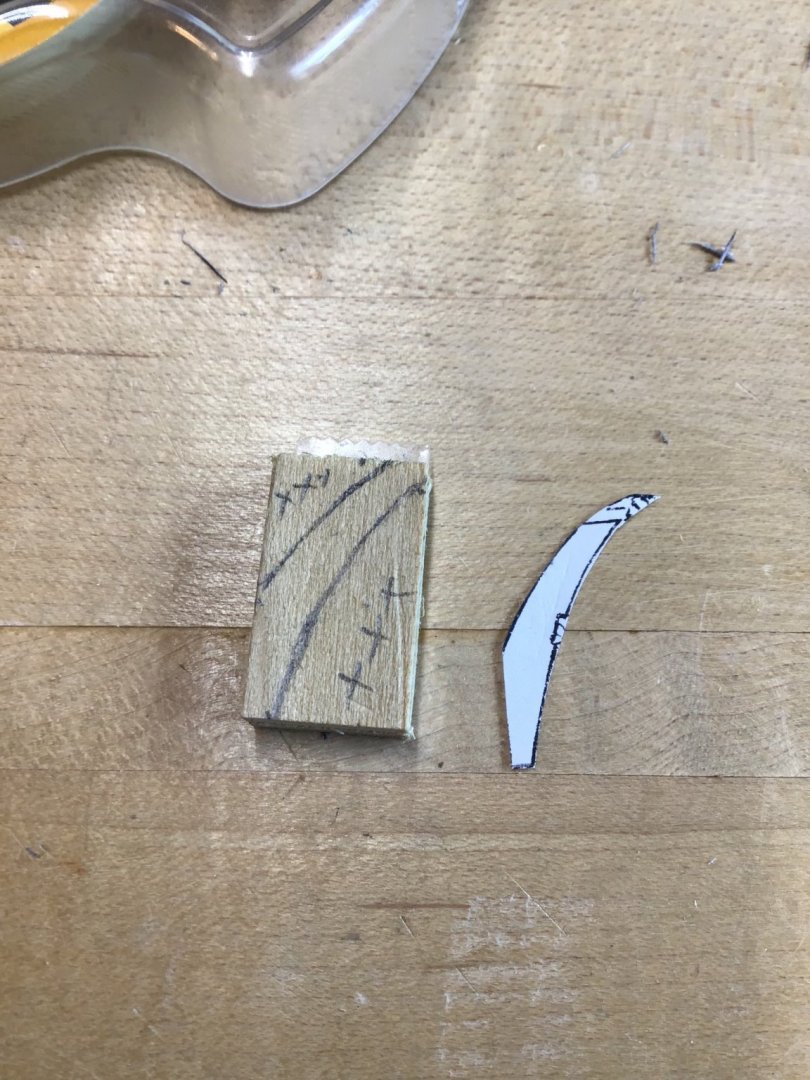
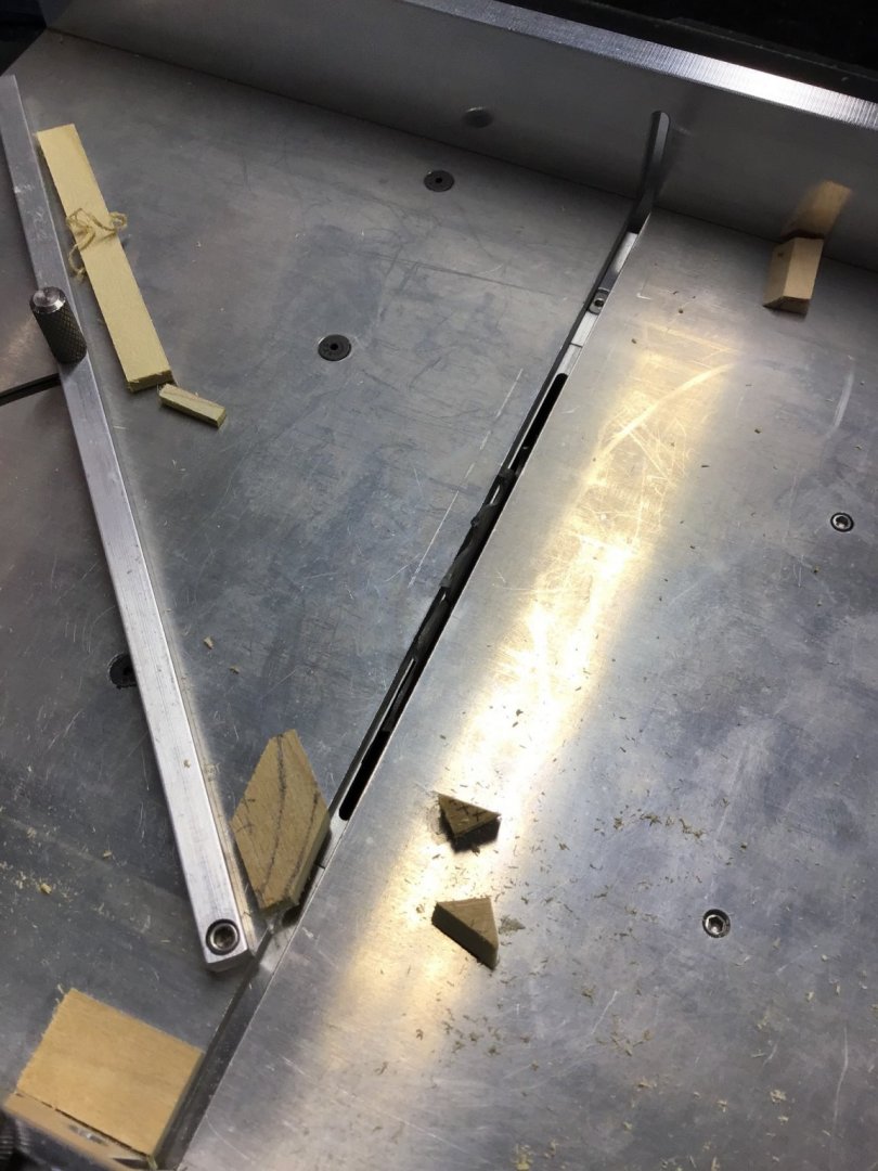
Making and Installing the Head Timbers Have the 3rd Head Rails partially shaped, but need the head timbers in place to guide the final shaping. Started by using the plan to determine the dimensions of the required blank for Timber 3. Picture 1 shows the dimensions of 9/16” by 15/16” and two blanks taped together with double sided tape. The blanks are popular. Hardwood is best for sharp and crisp corners. Next use a template to mark up the blank. We are taking advantage of the lower left corner and the horizontal top of the blank. Picture 2 Picture 3 shows chunks of waste wood, cutoff with the table saw. The Foredom drill press with the drum sander makes quick work of shaping the piece. Picture 4 The timber is glued to the stem, with a section of the plan used as a spacer.


-
Hello friend from Massachusetts USA. Good luck with your ship model!
-
Nice idea regarding the black bristles….model looks really good, Congrats!
-
Greetings from Massachusetts and good luck with your project!
-
Welcome to MSW, always open to answering a question if you need a hand. Good luck with your project!
-
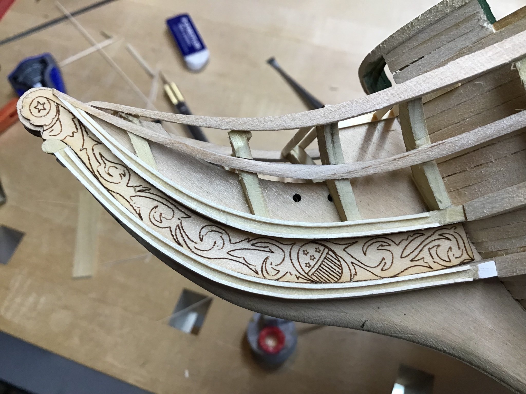
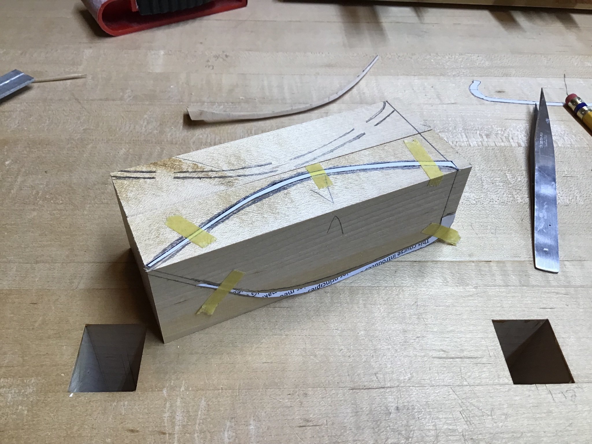
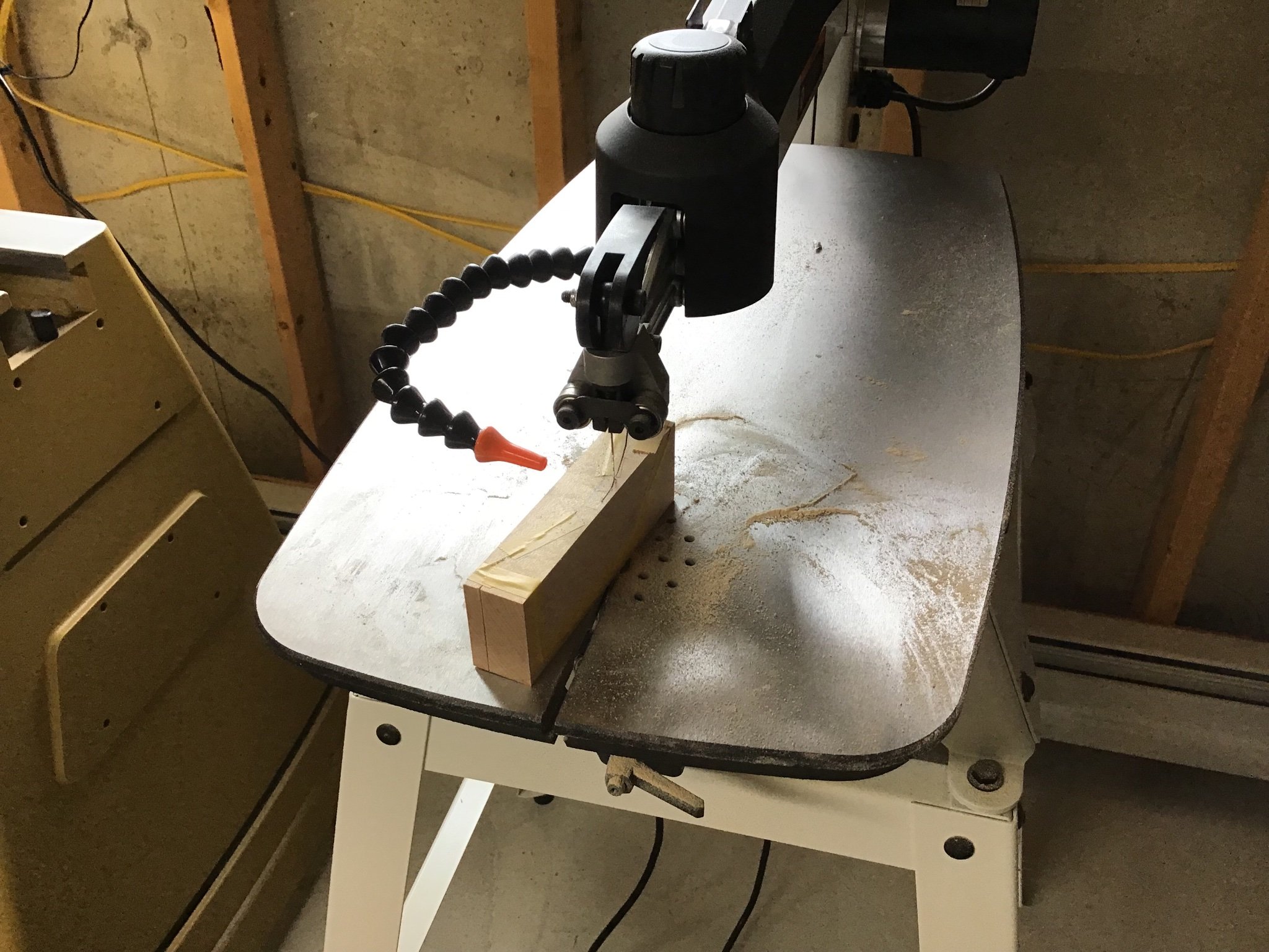
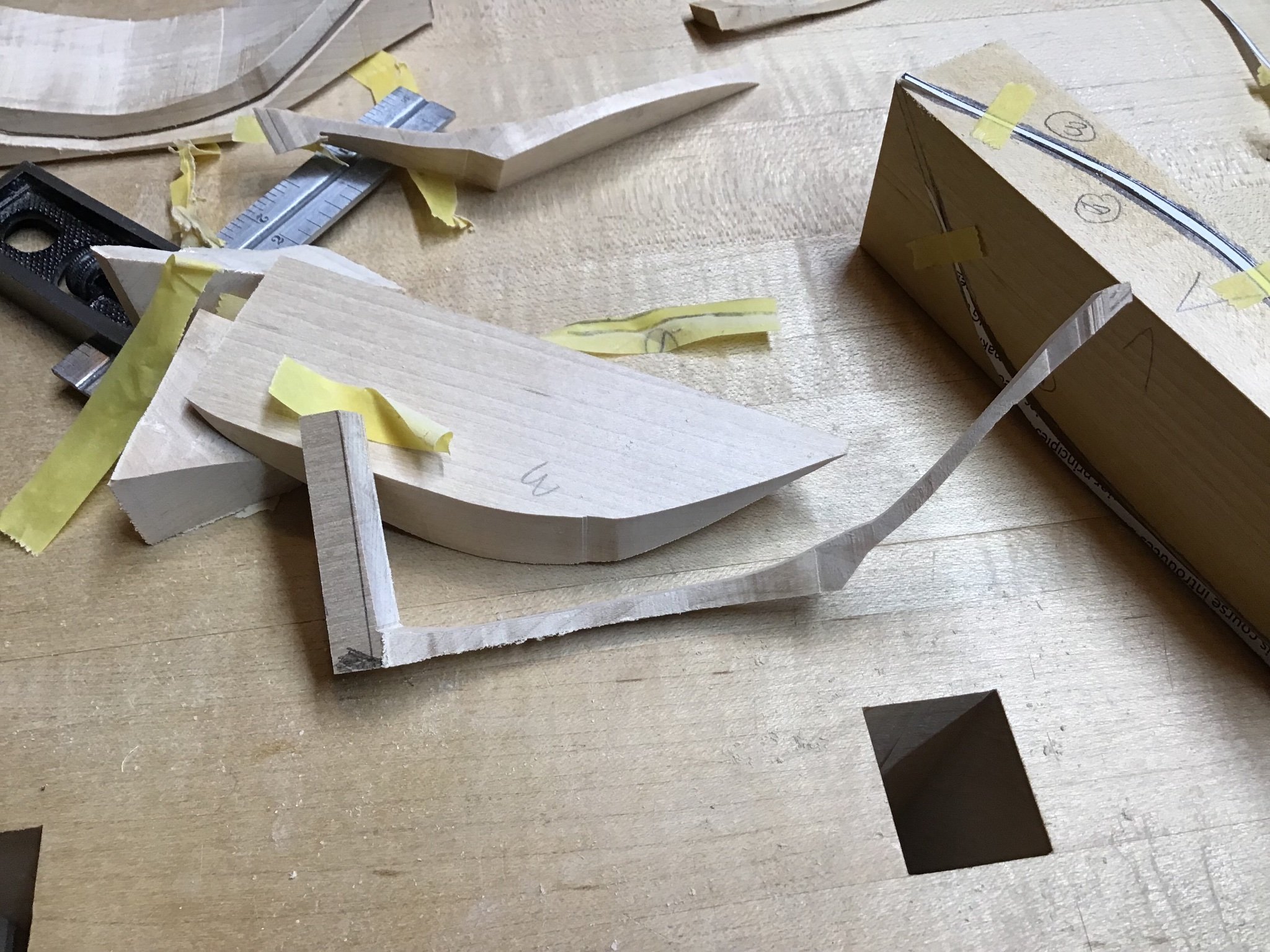
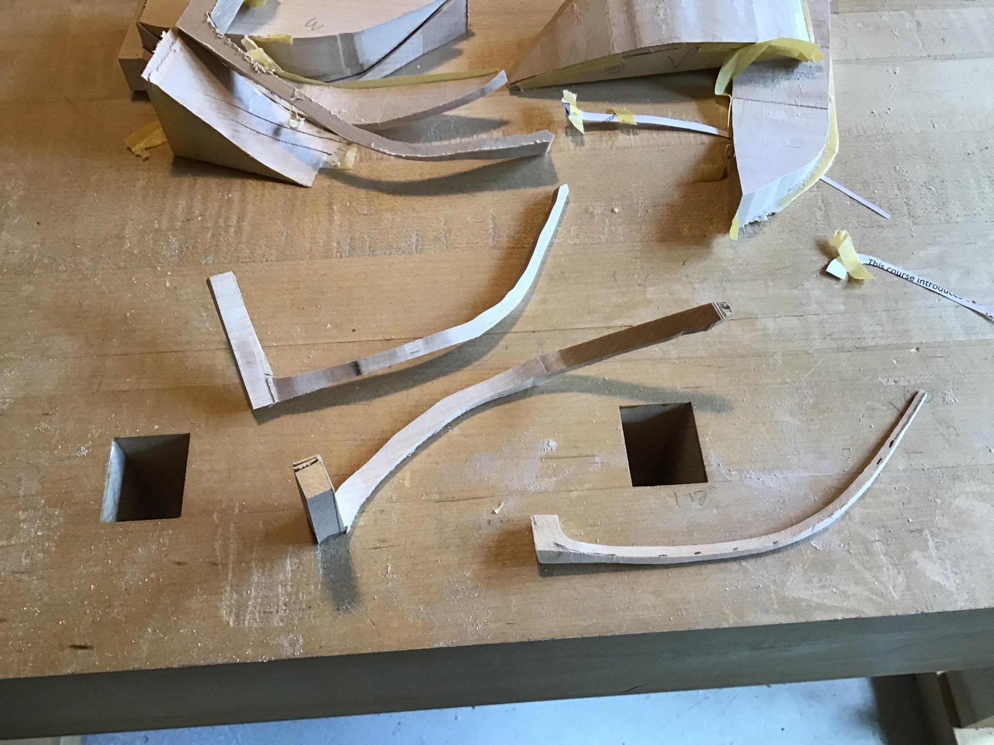
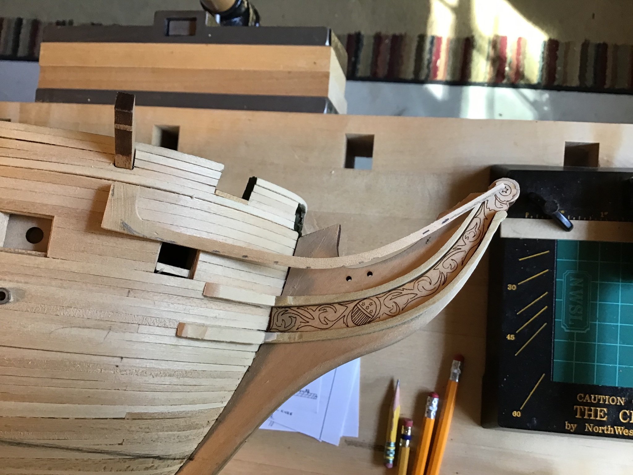
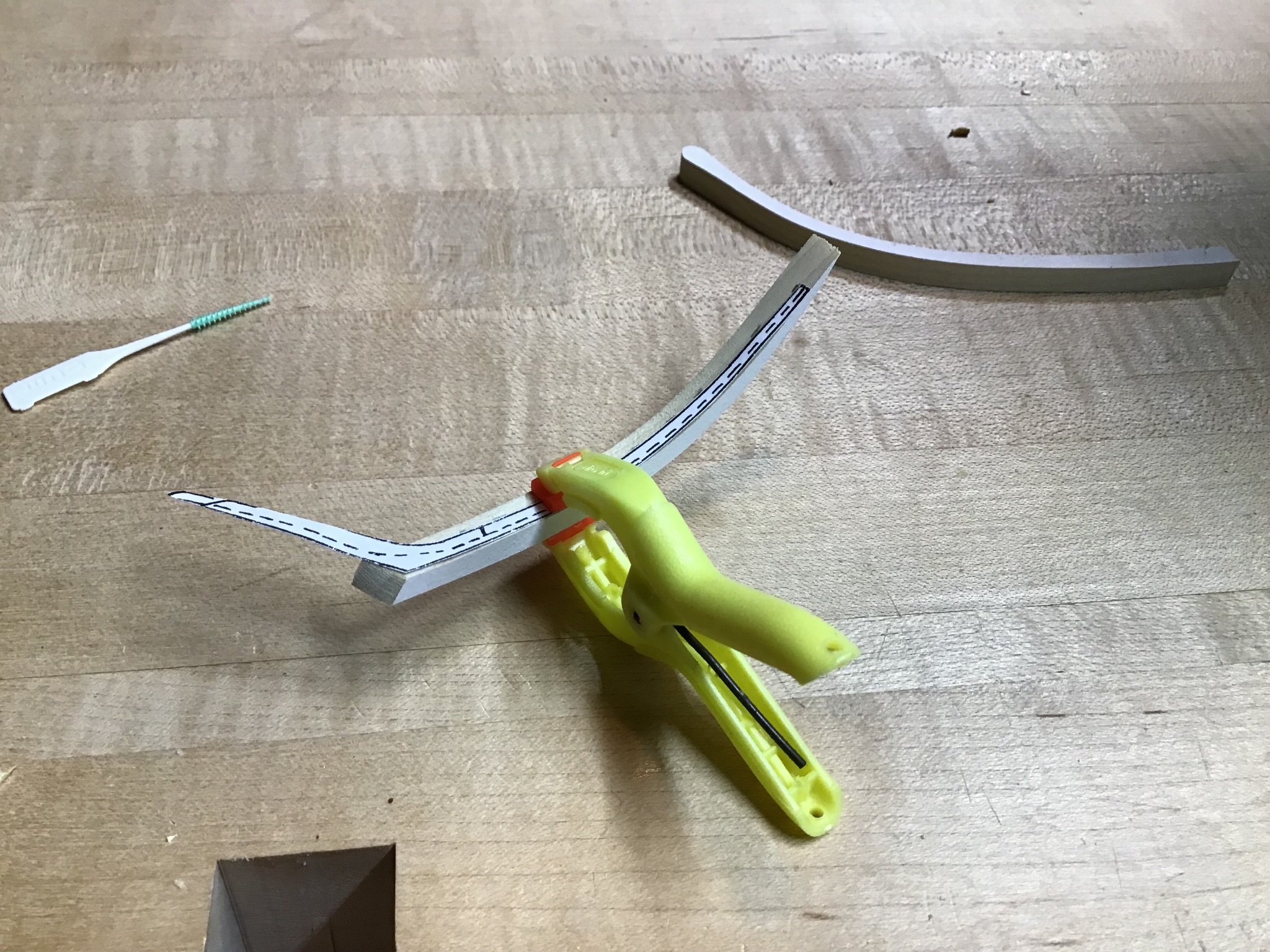
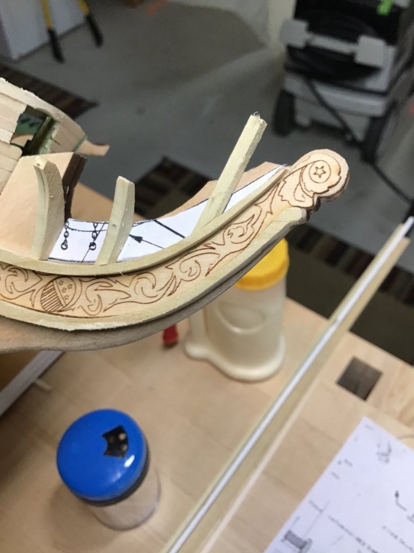
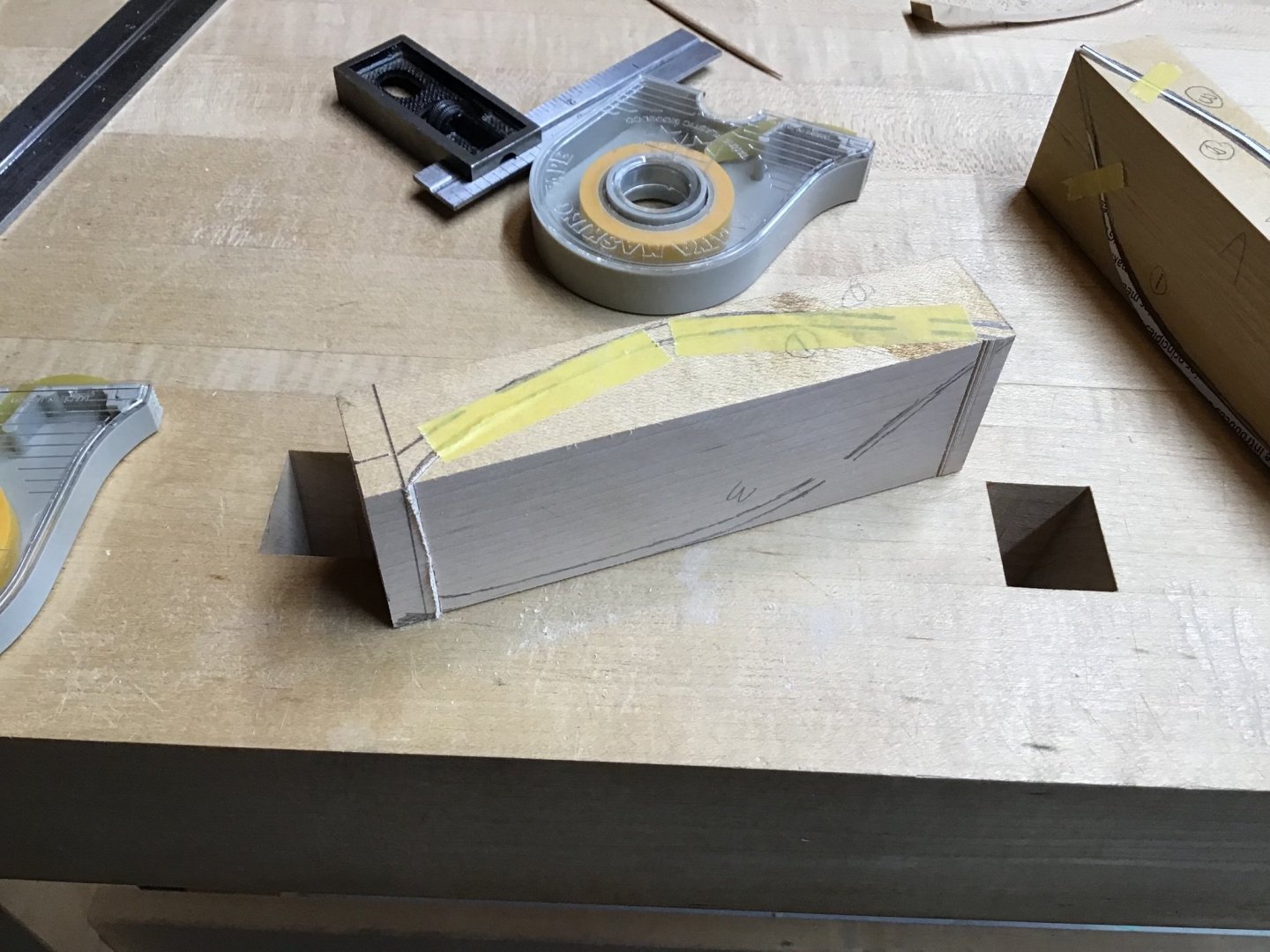
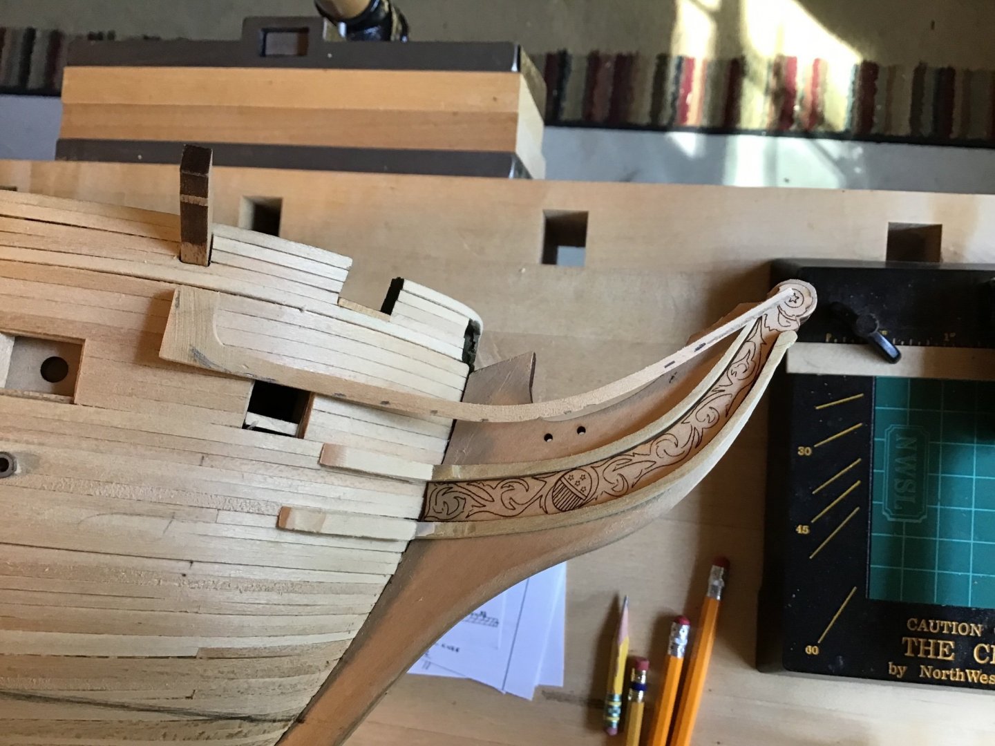
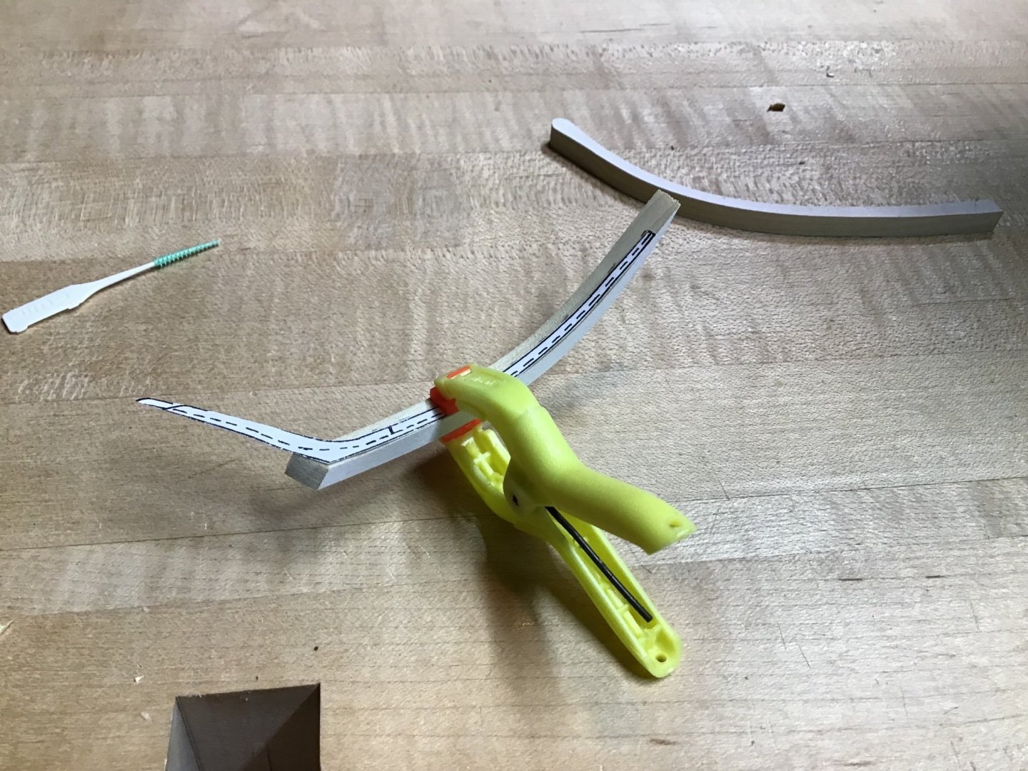
Third Head Rail - Rough Cut Making the 3rd Head Rail from a single piece, from a block of hard maple cut on the scroll saw. The technique is the same used in furniture building to make a cabriole leg, (YouTube example). First is to determine the dimensions of the wood block. Using the plan the block dimensions were determined to be: 4 7/8” long, 1” thick, and 1 5/8” high. Next templates of the profile and plan view were used to line out the blocks - Picture 1 shows port and starboard blocks. The scroll saw was used to cut the block, and after each cut the block was taped back together - Picture 2. Picture 3 shows the block on the saw. Picture 4 shows the result after making all the cuts and breaking away the pieces. Picture 5 shows the port and starboard rough rails, and a starboard rail, previously made. partially shaped. Use the templates to mark lines as necessary. Last picture shows that rail in place, with final shaping yet to be completed.


-
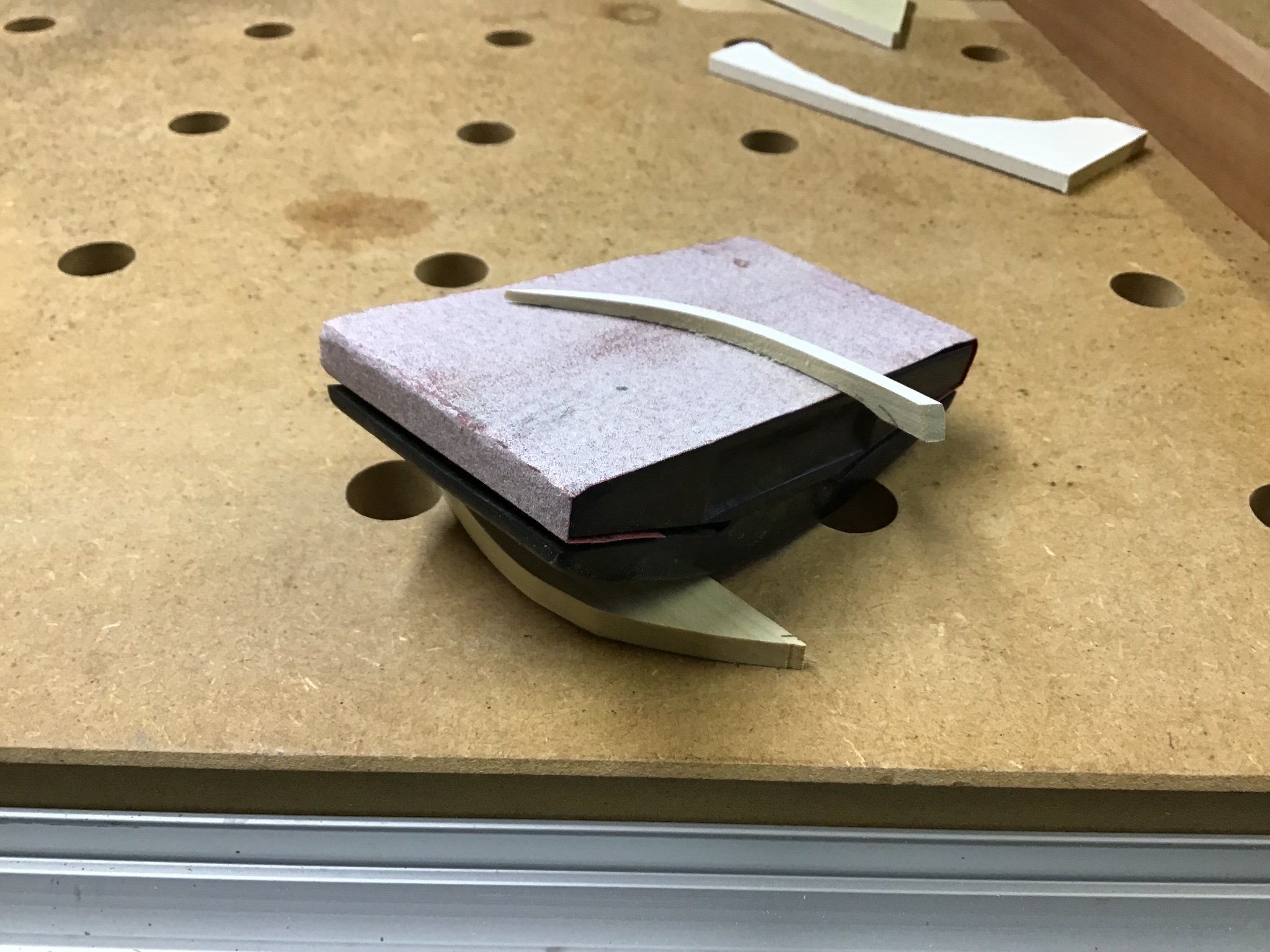
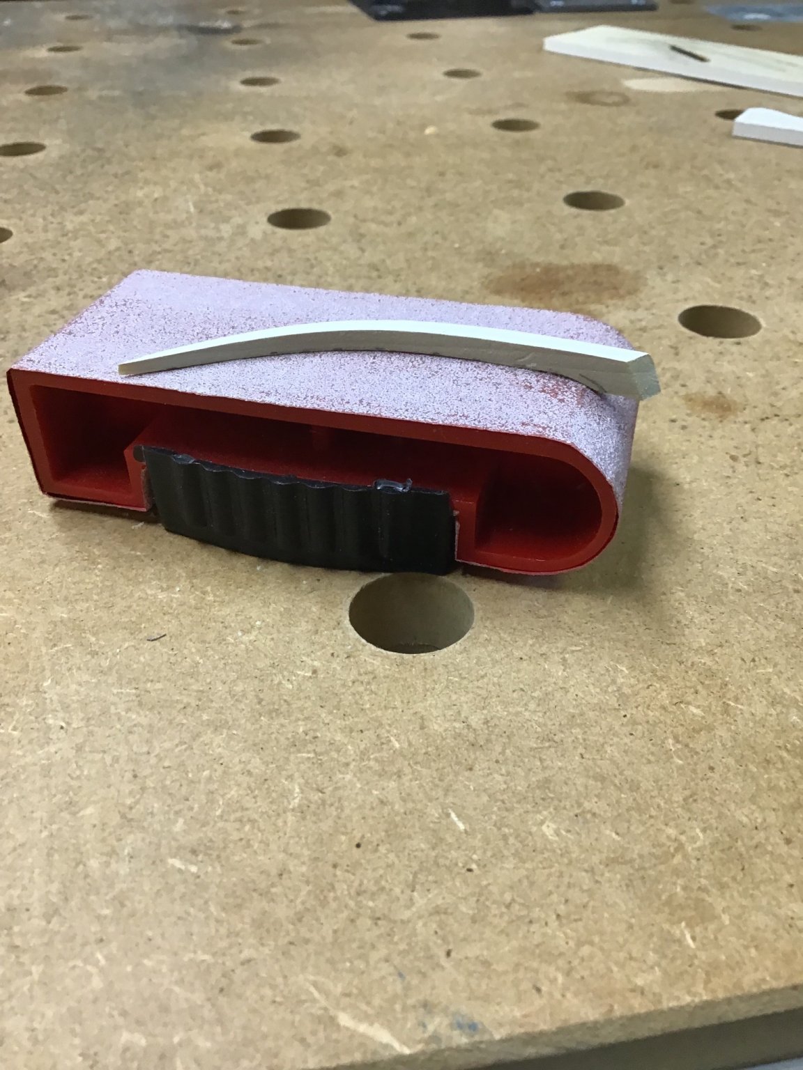
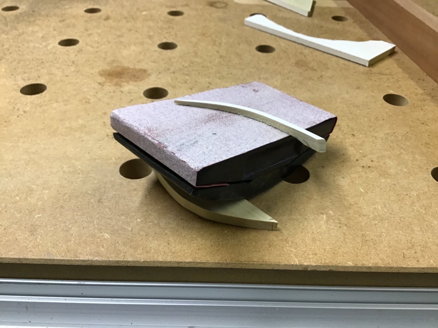
Cheek Knees and Rails - Part 2 A picture of using the template to mark the fore to aft taper on top of the rail. And flattened the taper, outboard face, flat with a sanding block. and this block to help with the curve

-
Thanks Boats, one motivation for doing the log is a record to refer to when I don’t remember how I did it the next time around…. About the trailboards, the College of Model Shipbuilding Guide shows how to make relief carvings from plastic stock, I’m not ready for that. Plan to seal the boards, then airbrush paint white, then paint the black areas and the shield with a fine brush. I think to the casual observer it will look the same as the real thing…. For the white trim, plan to also airbrush paint white, then mask the white paint and paint the remainder black. The CMS guide shows how to use plastic for the trim. However, I think plastic on wood is kind of out of character, plus there isn’t, in my opinion, such a difference between applied trim time and paint, that justifies the extra time. Happy Labor Day!