HOLIDAY DONATION DRIVE - SUPPORT MSW - DO YOUR PART TO KEEP THIS GREAT FORUM GOING!
×

ERS Rich
-
Posts
733 -
Joined
-
Last visited
Content Type
Profiles
Forums
Gallery
Events
Everything posted by ERS Rich
-
 Good Morning, For the wale, a possibility is making a vertical cut and removing a section say aft of the gunport to the stern, and adding new wale. The issue with loss of shape of the counter sides may not be an issue after the counter is planked. Maybe build up the inboard sides of these pieces with planks for more contact area when fitting the counter planks. Regarding technique, a half round file gives exact control of wood removal vs sandpaper. Personally I rarely use sandpaper. Have a good one.
 -
Thanks everyone, the feedback is much appreciated. On to some plastic subjects for a while….. Holidays are coming up, enjoy yours! -Rich
- 166 replies
-
- 4
-

-
- Maine
- BlueJacket Shipcrafters
- (and 1 more)
-
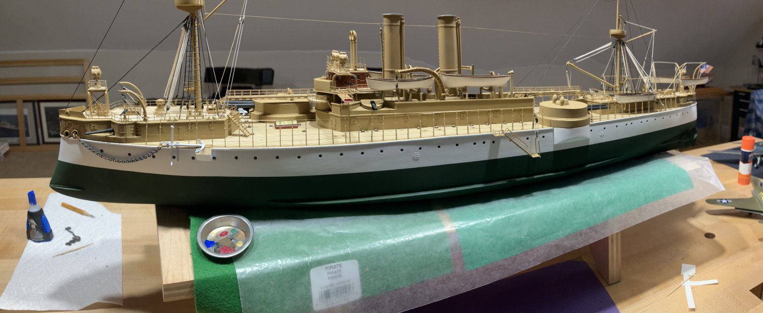
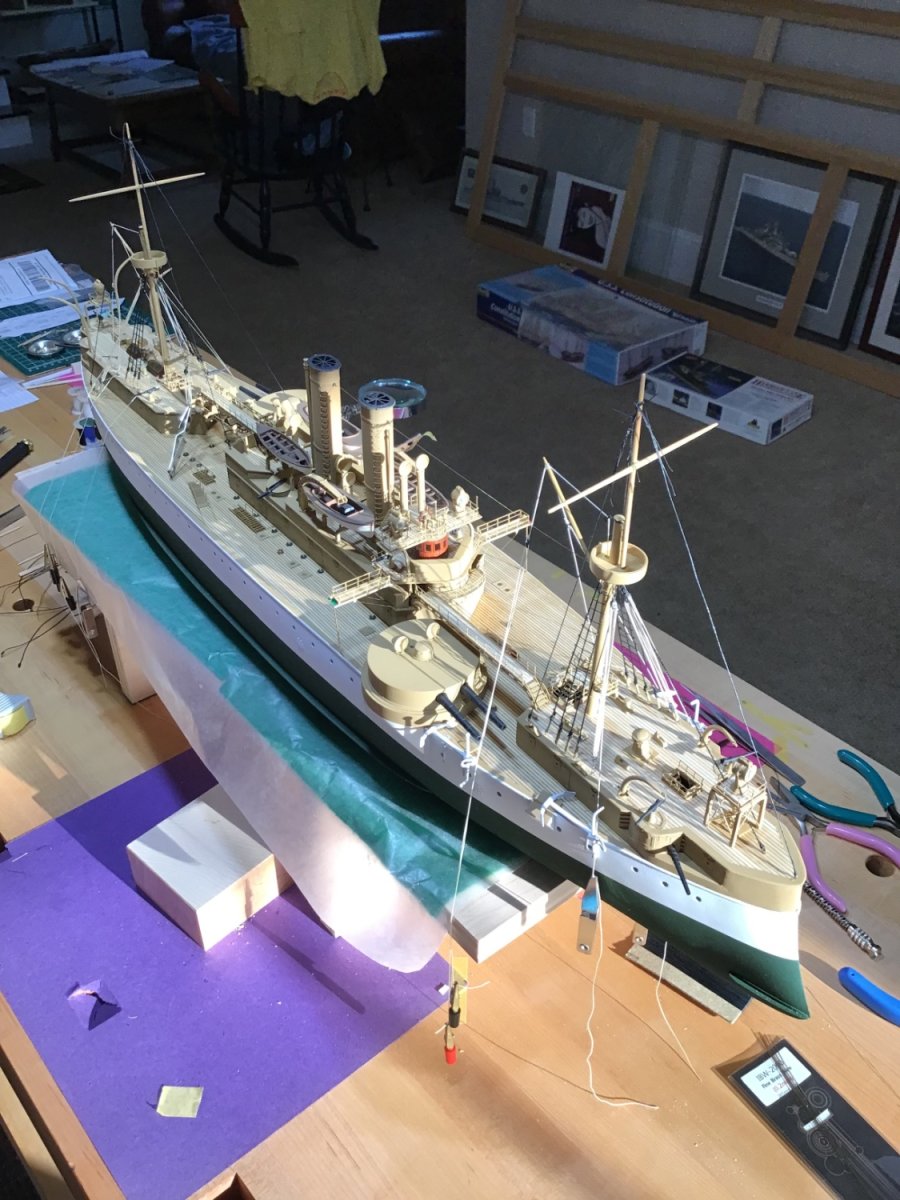
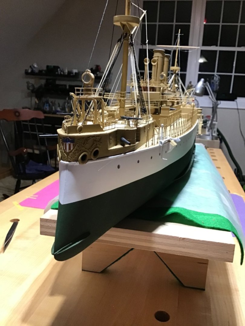
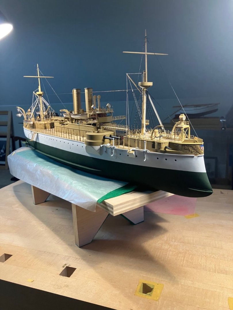
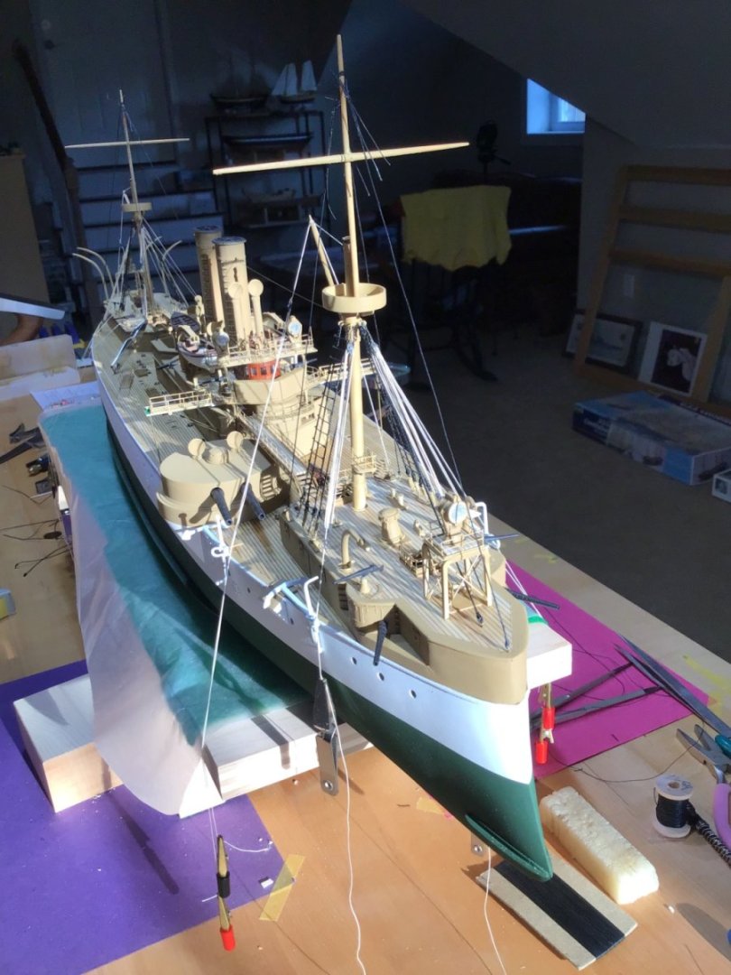
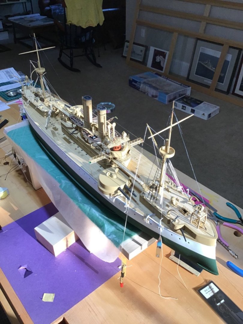
Finished and Epilog Making the call that she’s finished since the minor work remaining won’t impact any pictures. Look for photos of her cased in the gallery, probably in a month or so. Here as a panoramic photo taken with my iPhone. Epilog What an experience. The kit has everything needed out of the box to build a beautiful rendition of the ship. The plans are good and I found the instruction booklet easy to follow. And there are many extra PE parts to cover mistakes. One comment about the plans is to understand that parts, say eyebolts are identified with a number and symbol. The eyebolt symbol appears in each location on the plan, however each symbol does not have a number. Notice that a part can be identified by looking on the plan, and in the bill of material in the instruction book. The bill of materials is divided by material type (wood, brass, casting, etc), then part name and quantity. If the instructions call to install a part and you do not know what that part looks like, find it’s name on the bill of material, ID what it’s made of, and the quantity, then look in the sealed bag for a quantity match. I also found the photos at the end of the instructions book helpful for identifying the smaller amidship stacks. Pay attention to part and component spacing, on the amidships superstructure in particular. Notice the center hatch on the amidships superstructure does not have a coaming, I added it to my model and much later found my stack spacing was slightly off. Much is happening on the amidships superstructure so make sure the components are spaced according to the plan. Last is part numbering, I did find a few inconsistencies between the booklet and plan. Not a big deal. Not much else to say other than it certainly is worth the effort. I’d say anyone who has a few kits under their belt, can take it on. That being said finishing is a major effort, an airbrush is suggested. My ship is finished with Tamiya and Vallejo acrylics. Finally Bluejacket is immediately available if you have a question. Just give them a call. Best of luck if you take this on. Feel free to message me if you have a question.

- 166 replies
-
- 16
-

-
-
- Maine
- BlueJacket Shipcrafters
- (and 1 more)
-
Boss! Someone said, a masterpiece is a collection of simple steps, each executed perfectly…..
- 282 replies
-
- 2
-
-
- Bluenose
- Model Shipways
- (and 1 more)
-
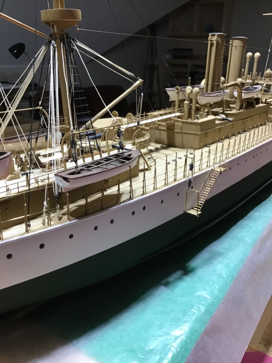
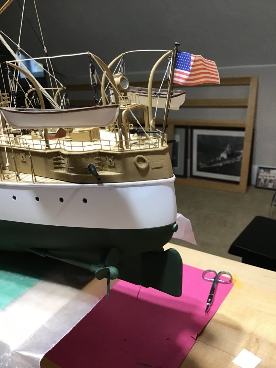
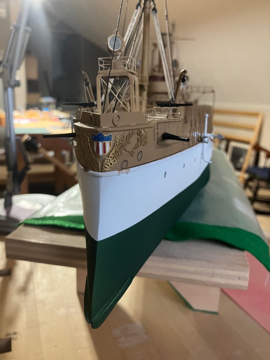
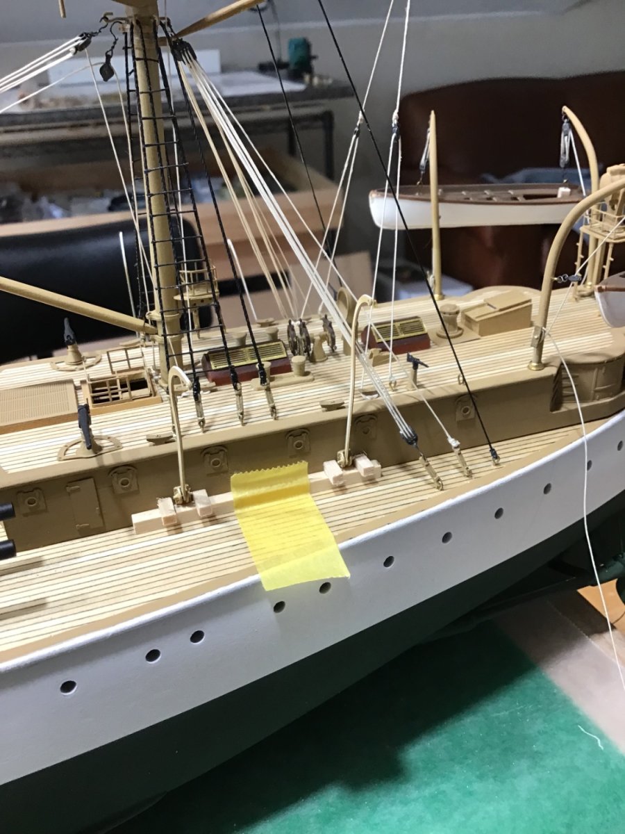
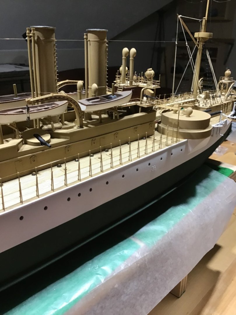
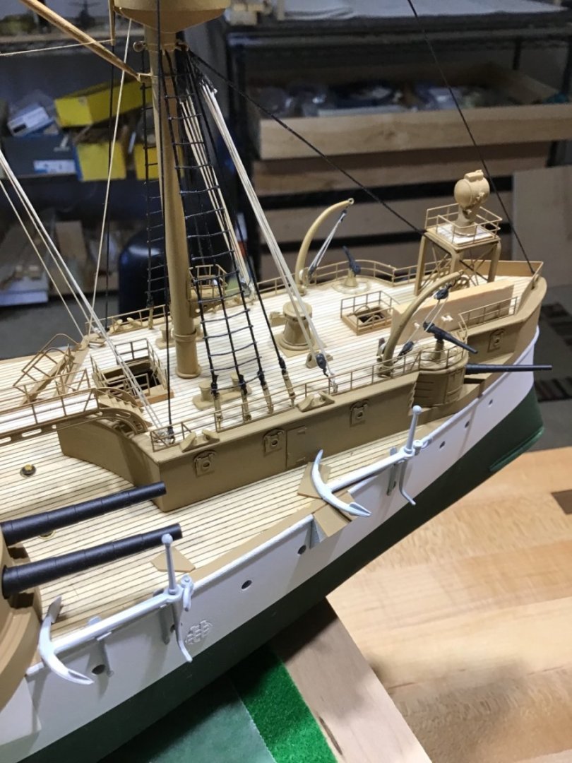
Various Photos Flag on the aft jack. Prefer to heavily crumple the paper flag. Also touched up white area on the stern. Finished up the hawse lips and bow ornaments. Views of the main deck stanchions. Line is bass wire, tried thread but to difficult to pass through the stanchion eyes.


- 166 replies
-
- 13
-
-
-
- Maine
- BlueJacket Shipcrafters
- (and 1 more)
-
Hi John. Is the 3/16” drill bit used to hold the ring for drilling a hole into the ring? Thanks for showing how it’s done. -Rich
-
Hi Alistair, Thank you very much for the kind words. Yes, this kit had everything needed to produce a fine model of the Maine. At the end, I’ll post thoughts on some things to be careful about when building this kit. And I do have another USS Maine kit that I’d consider selling along with USS Olympia if anyone is interested they can private message me. Given the price of shipping someone would have to be within driving distance! Cheers! -Rich
- 166 replies
-
- 4
-
-
- Maine
- BlueJacket Shipcrafters
- (and 1 more)
-
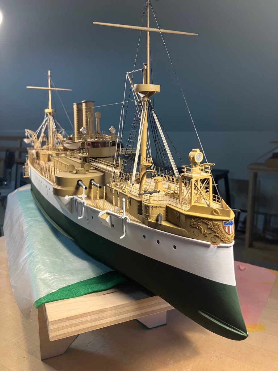
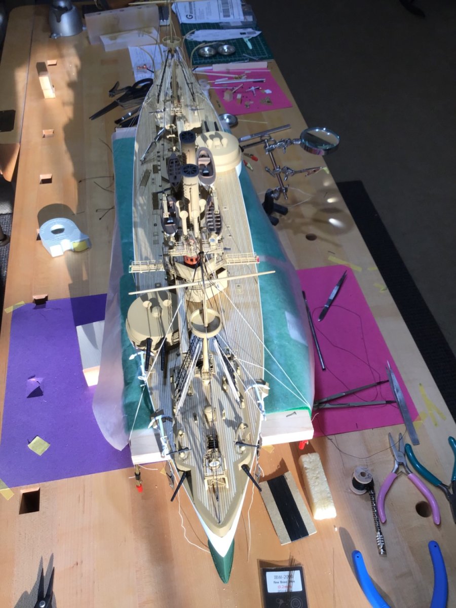
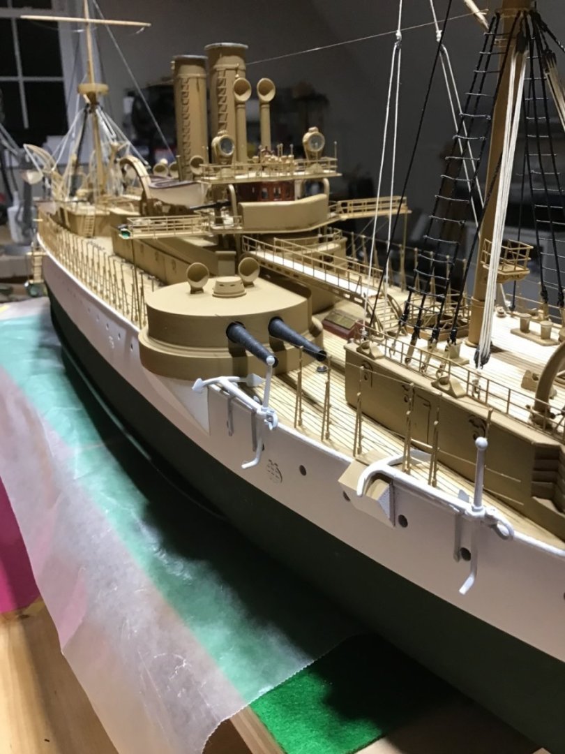
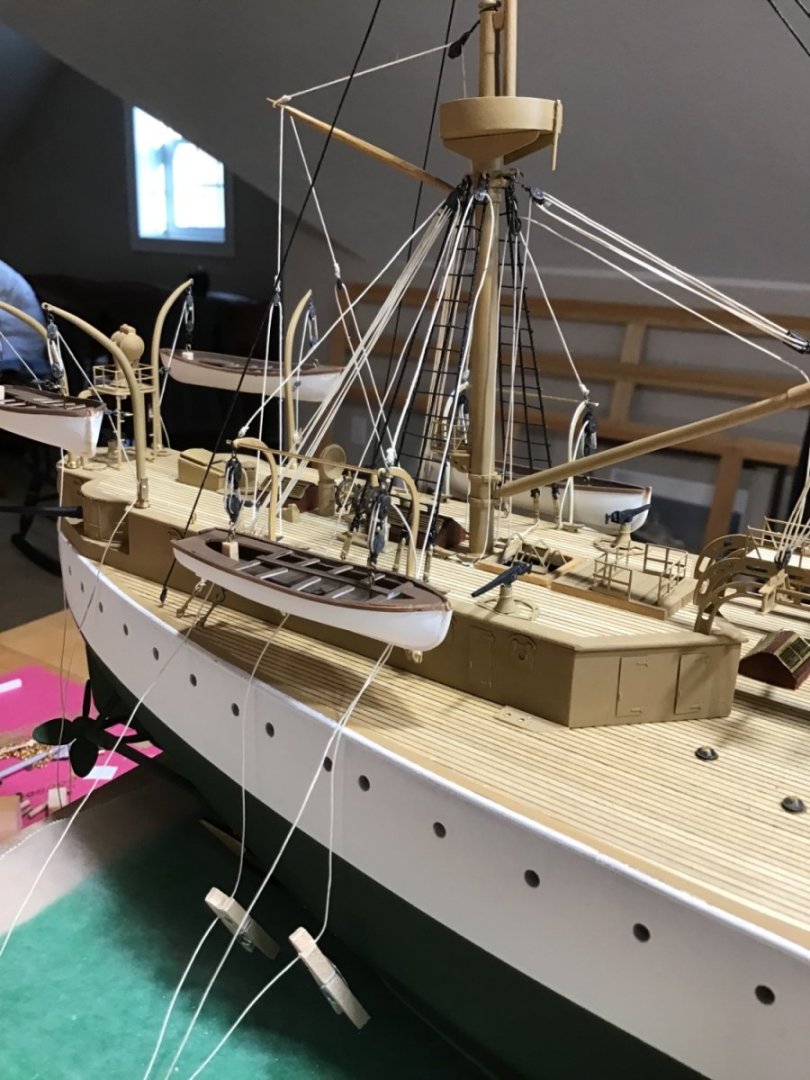
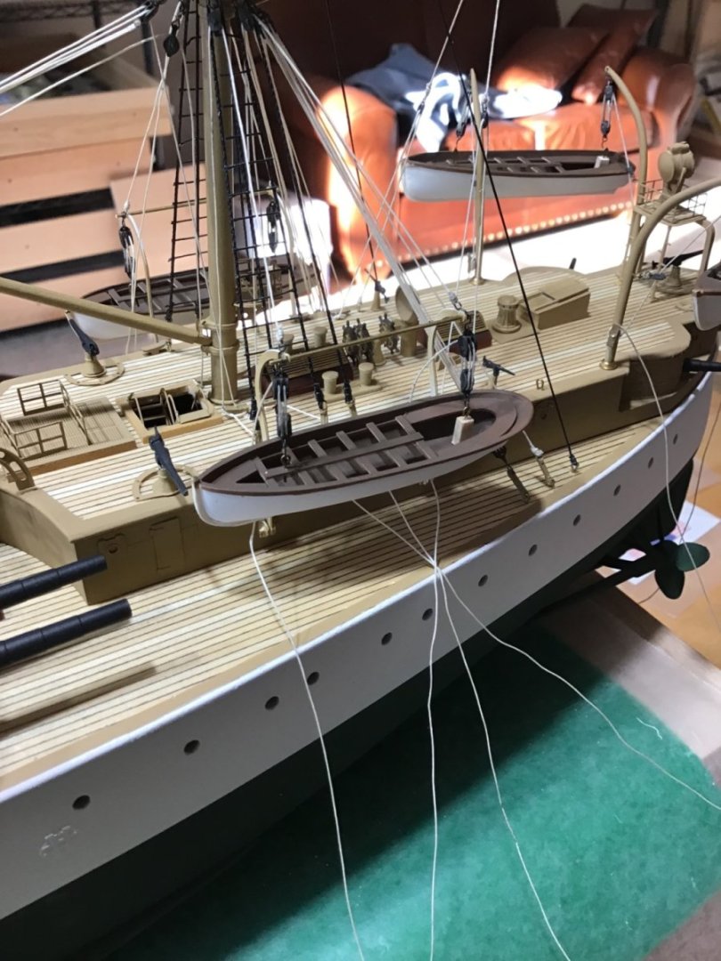
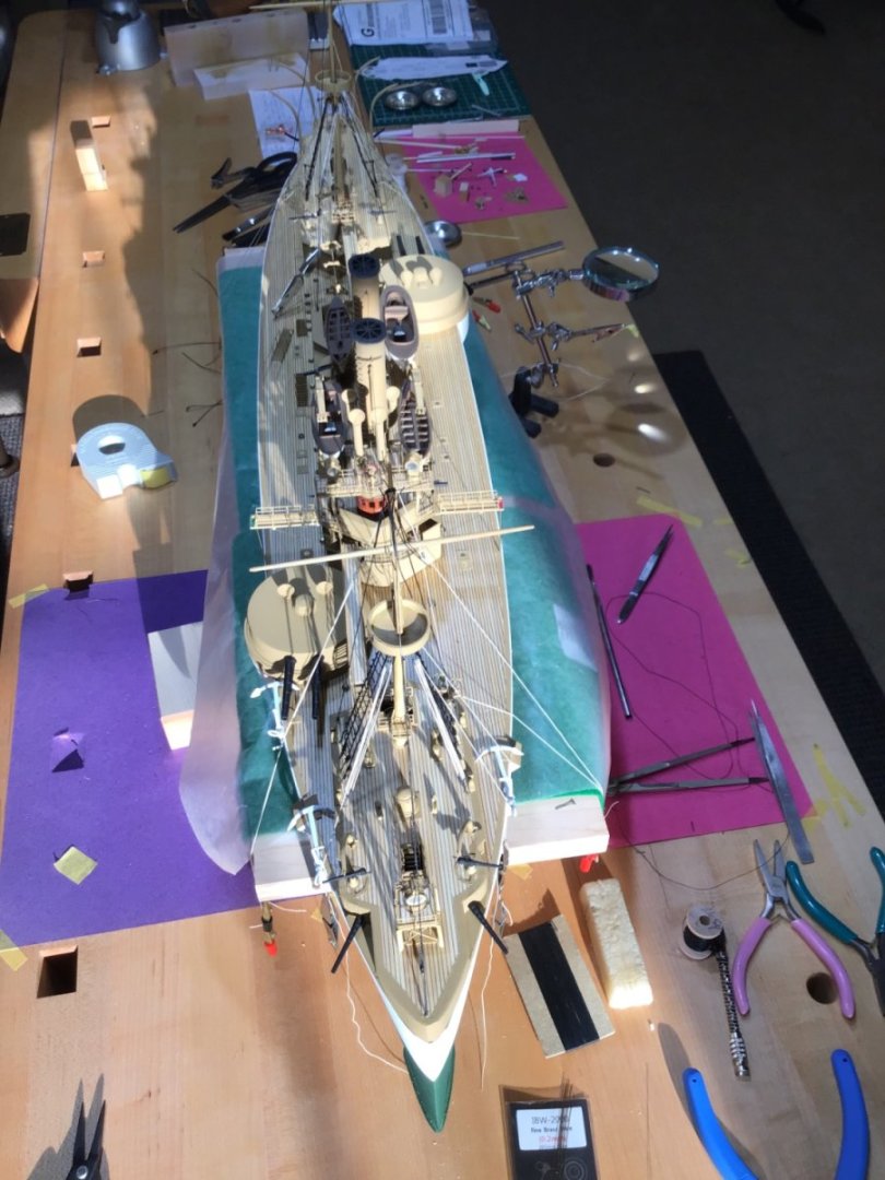
Home Stretch It’s getting down to it. Not many more tasks to do. The heavy lifting is over. Here is a shot of the bow ornaments. Followed by the entire ship with the main deck stanchions installed.


- 166 replies
-
- 16
-
-
-
- Maine
- BlueJacket Shipcrafters
- (and 1 more)
-
Hi Avi, Thanks for posting information about this different, from parrafin, type of wax. It’s interesting. Big advantages of wax for me is easy to apply and less cleanup to deal with. -Rich
-
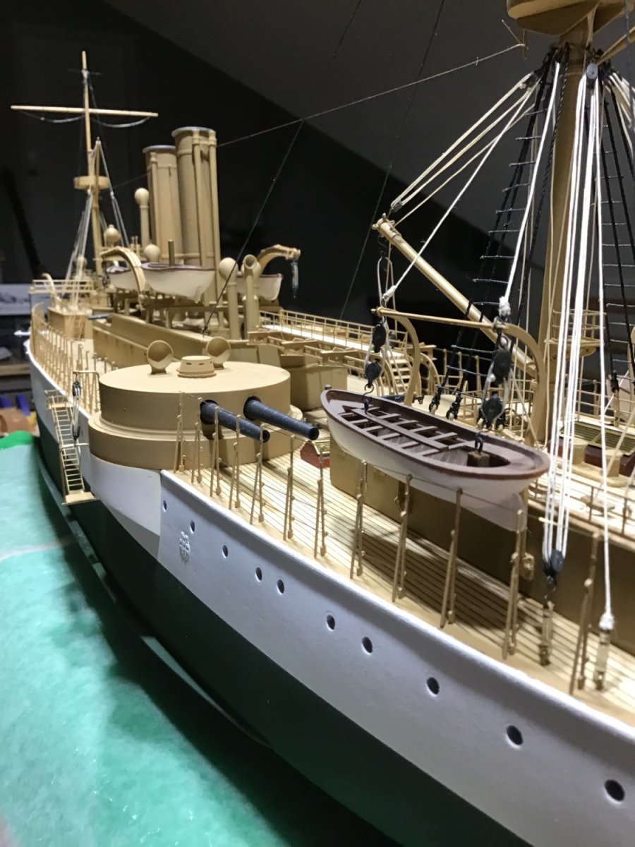
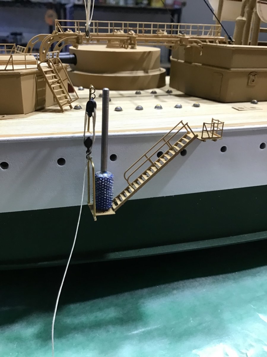
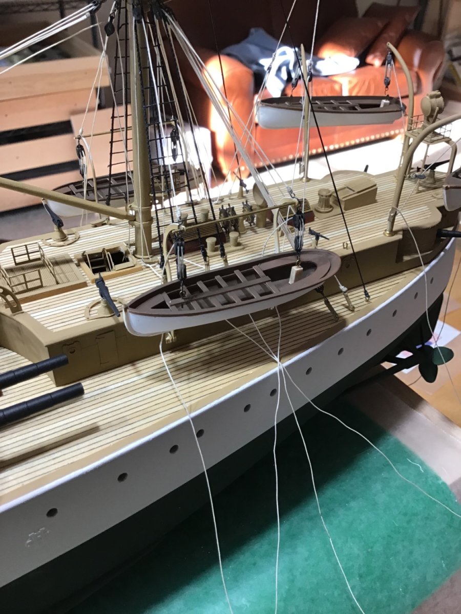
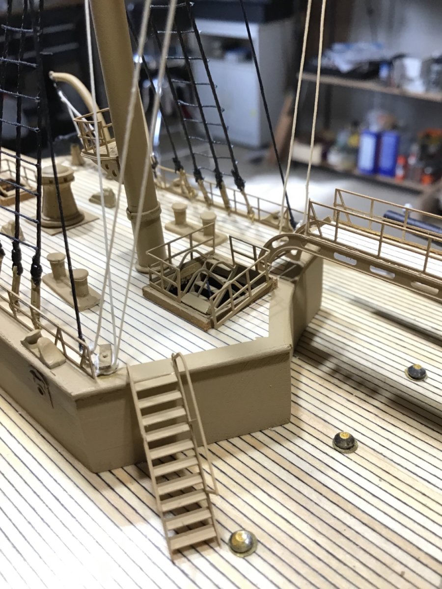
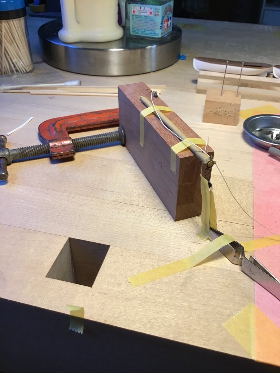
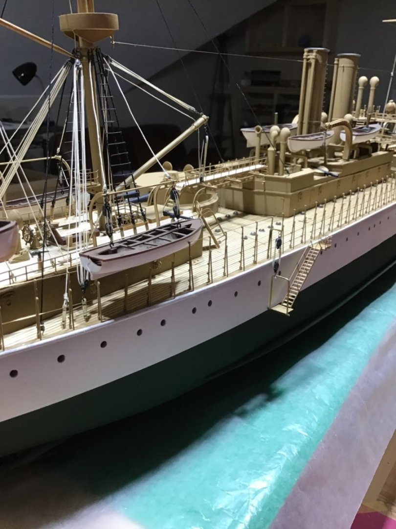
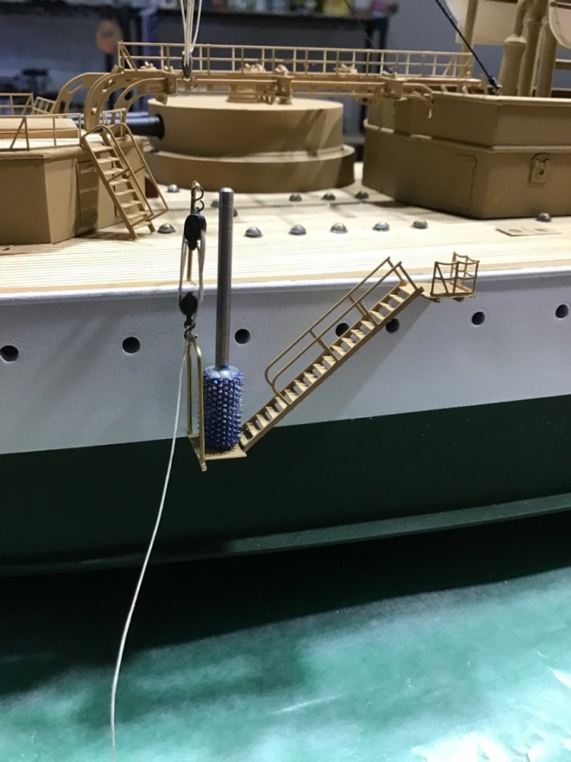
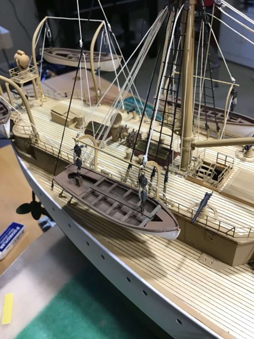
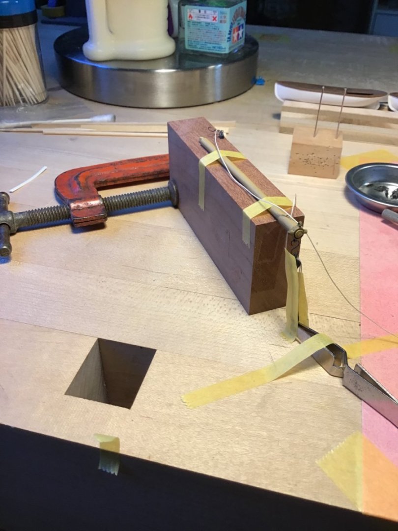
Accommodation Ladder and Railings Here's how the accommodation ladder install went. Two brass rods under the top platform. Using the bit as a weight on the lower platform for tension in the block ropes, then liquid CA on the ropes. Added the U shaped rod, seems to make sense, may redo it seems a little out of scale. Railing install pretty straight forward - use little dots of CA in the corners instead of along the bottom of the whole piece.
- 166 replies
-
- 9
-
-
- Maine
- BlueJacket Shipcrafters
- (and 1 more)
-
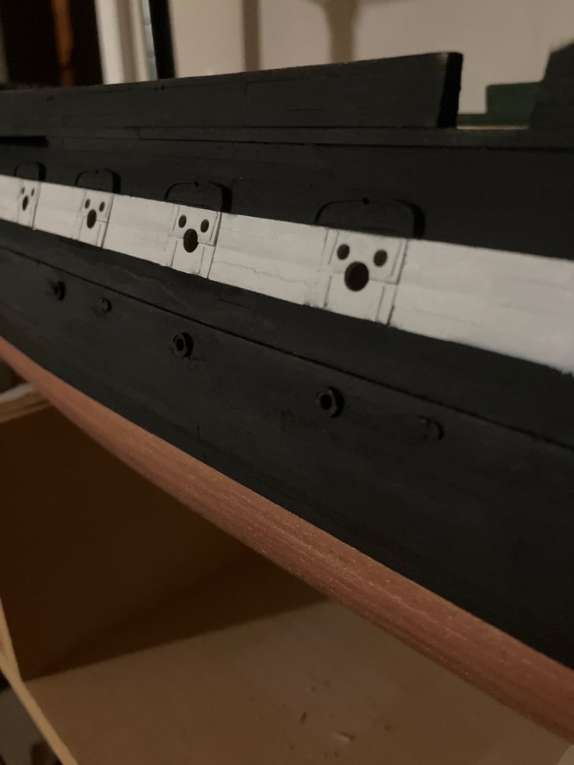
Hello, Yes, the text is/was incorrect. I can’t recall exactly, but I did either rip the kit stock to what was needed, or made my own. The Byrnes table saw is a valuable tool. My Constitution is on hold at the moment. Photo below shows the gun-ports with the covers installed. Cheers, -Rich
-
Good Morning, Will make the case, thinking of cherry hardwood and probably plexiglass panels to minimize the weight. Need to source a sheet of cherry faced plywood. I have some Kusmi #1 button shellac that looks nice on cherry (shellac.net). Have a good weekend. -Rich
- 166 replies
-
- 5
-
-
- Maine
- BlueJacket Shipcrafters
- (and 1 more)
-
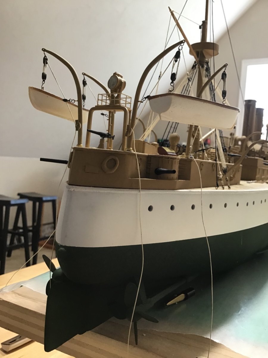
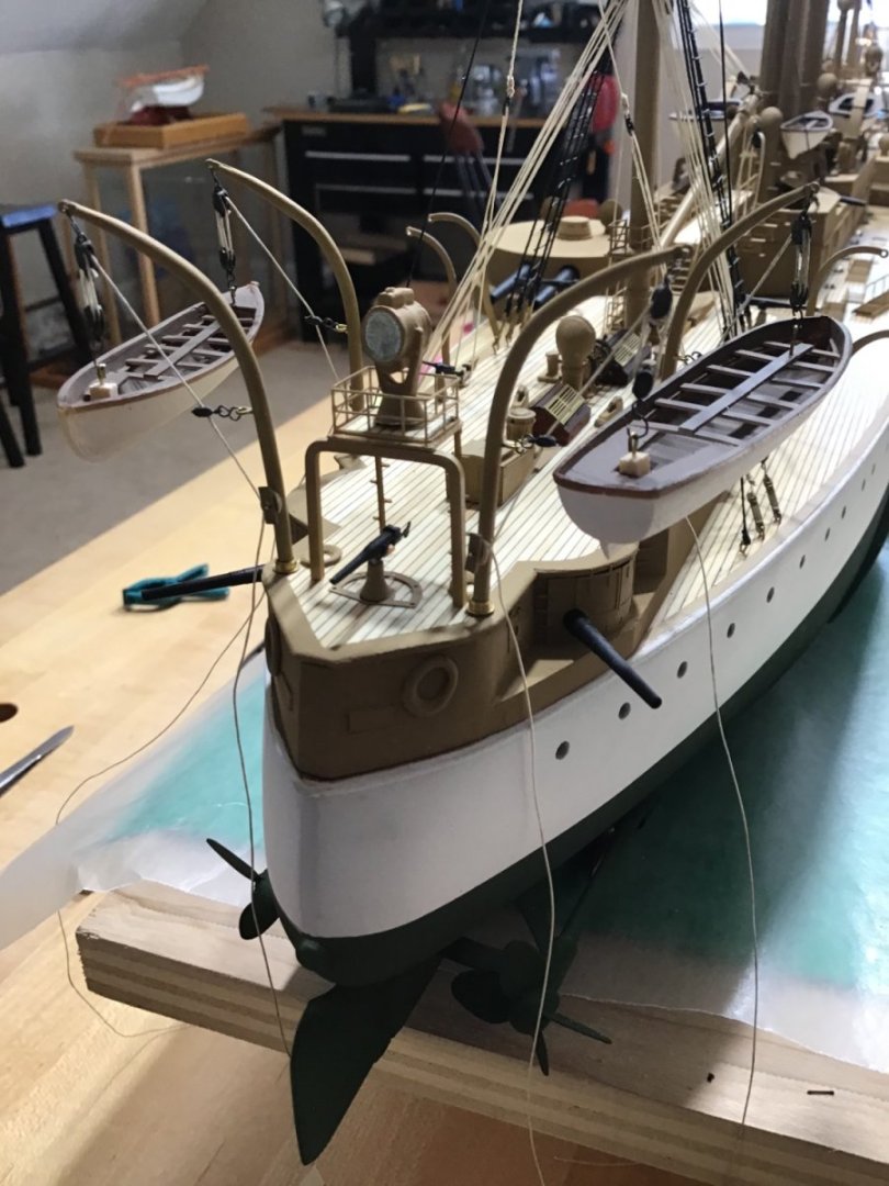
Aft Boat Davits Rigged the davits, and radial davits this week. I like to get everything in place, to make sure everything fits before tying off the lines. Just love how this is looking. Made a little jig to help place the davits.


- 166 replies
-
- 11
-
-
-
- Maine
- BlueJacket Shipcrafters
- (and 1 more)
-
Hello in New Zealand! Thank you, for the encouragement. Oct 4 will be one year, and it looks like I’ll finish by then, outside of the case. Looking forward to building several 1/32 aircraft. Nice break from so much construction. Rigging the cranes tomorrow, then just the companionways to construct, and finally the scroll details. Cheers Alistair
- 166 replies
-
- 3
-
-
- Maine
- BlueJacket Shipcrafters
- (and 1 more)
-
Hello Michael, Welcome to MSW. Congrats on finishing your project. That’s a huge accomplishment. Best if luck on the next one! Cheers, -Rich
-
Hi Giuseppe, welcome to the forum and best of luck on your projects! -Rich
-
Hello George, Welcome and it’s good to know you. Your ship is coming along nicely. There is a topic called “At a Glance” where progress pictures are posted. Check it out. -Rich
-
Hi Fred, glad to know you! -Rich
-
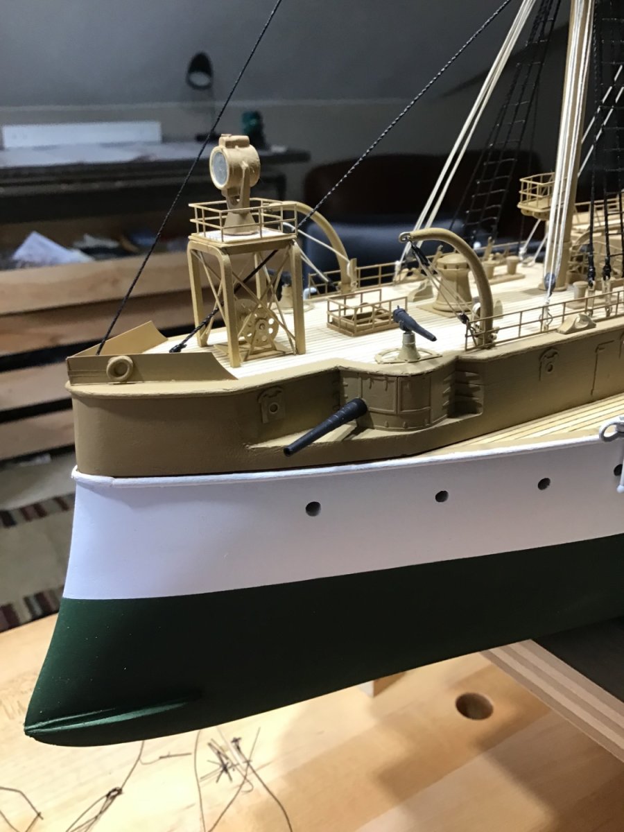
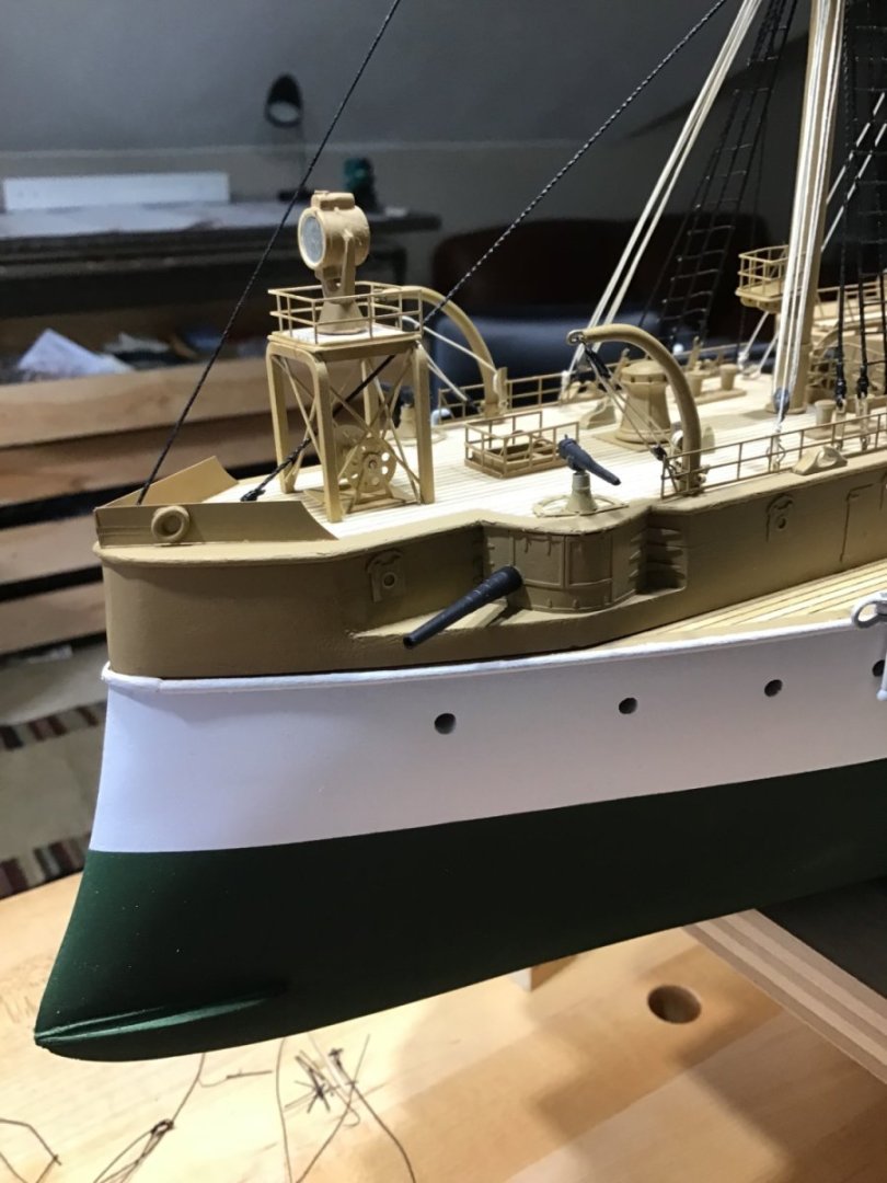
Forward Superstructure Rigging Finished the forward rig and started the railings.


- 166 replies
-
- 11
-
-
-
- Maine
- BlueJacket Shipcrafters
- (and 1 more)
-
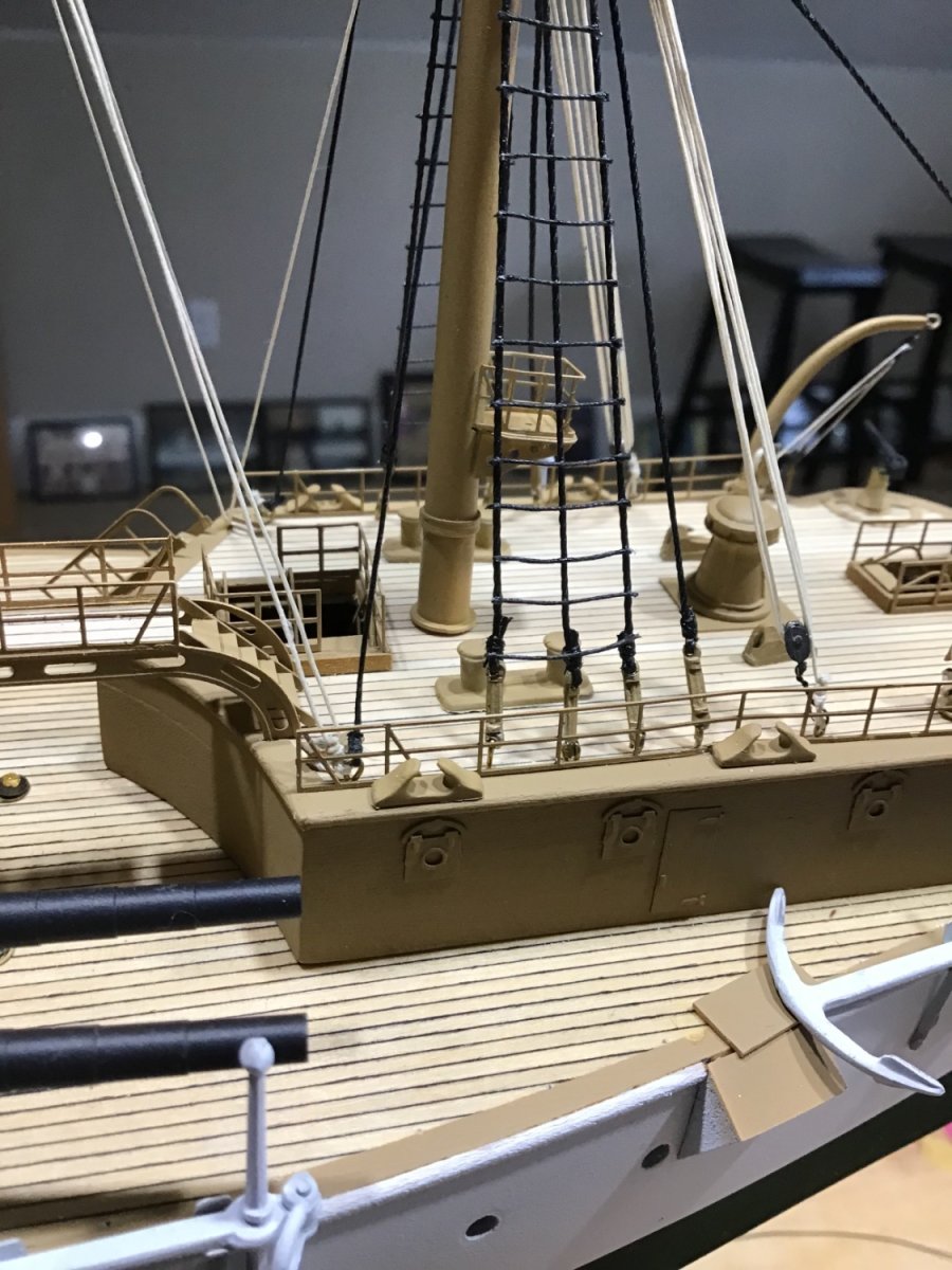
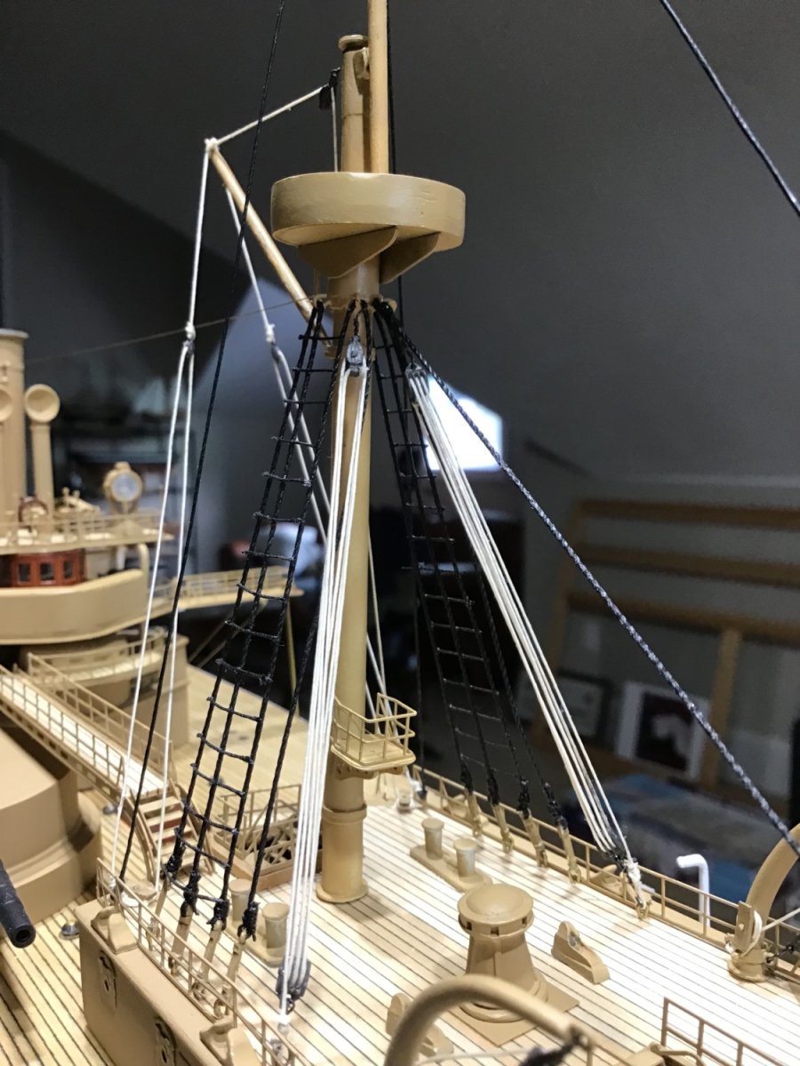
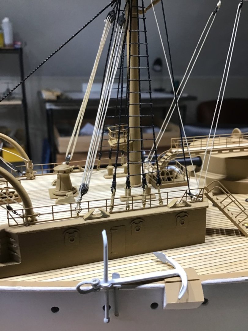
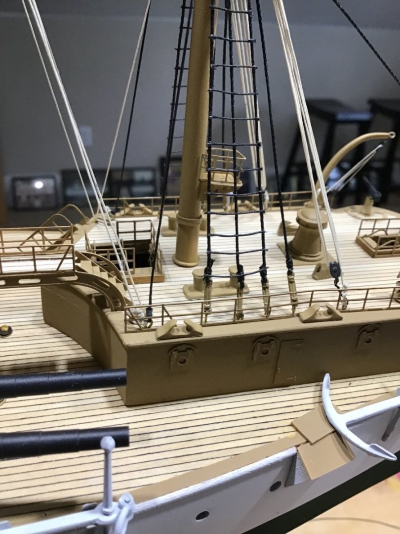
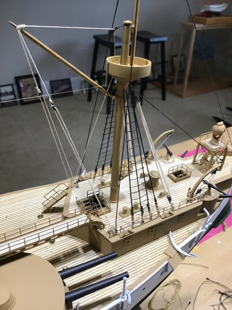
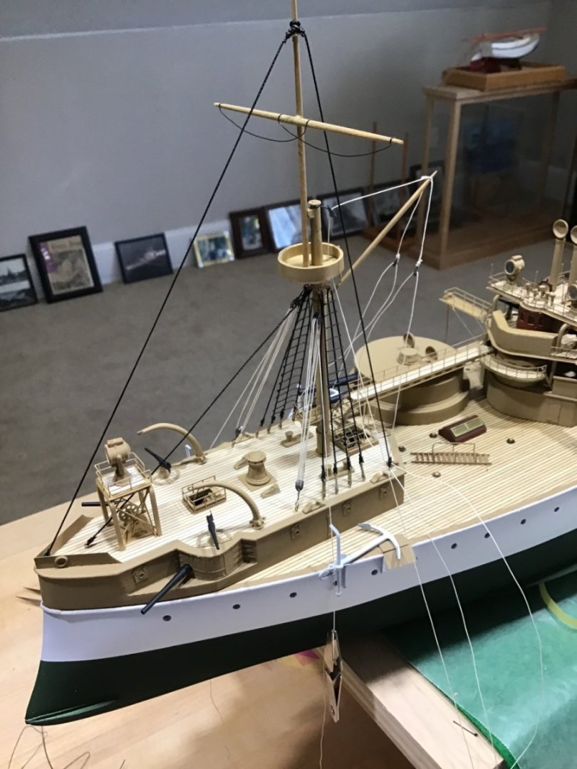
Rigging -Continued At this point the standing and running rigging associated with the masts is installed but not belayed - tied off. Sun in the shop this afternoon put light on the subject. Have a good weekend!

- 166 replies
-
- 11
-
-
-
- Maine
- BlueJacket Shipcrafters
- (and 1 more)
-
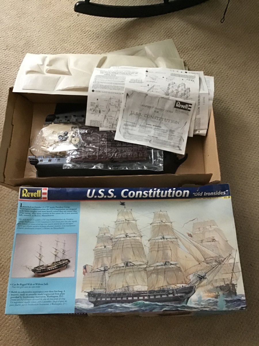
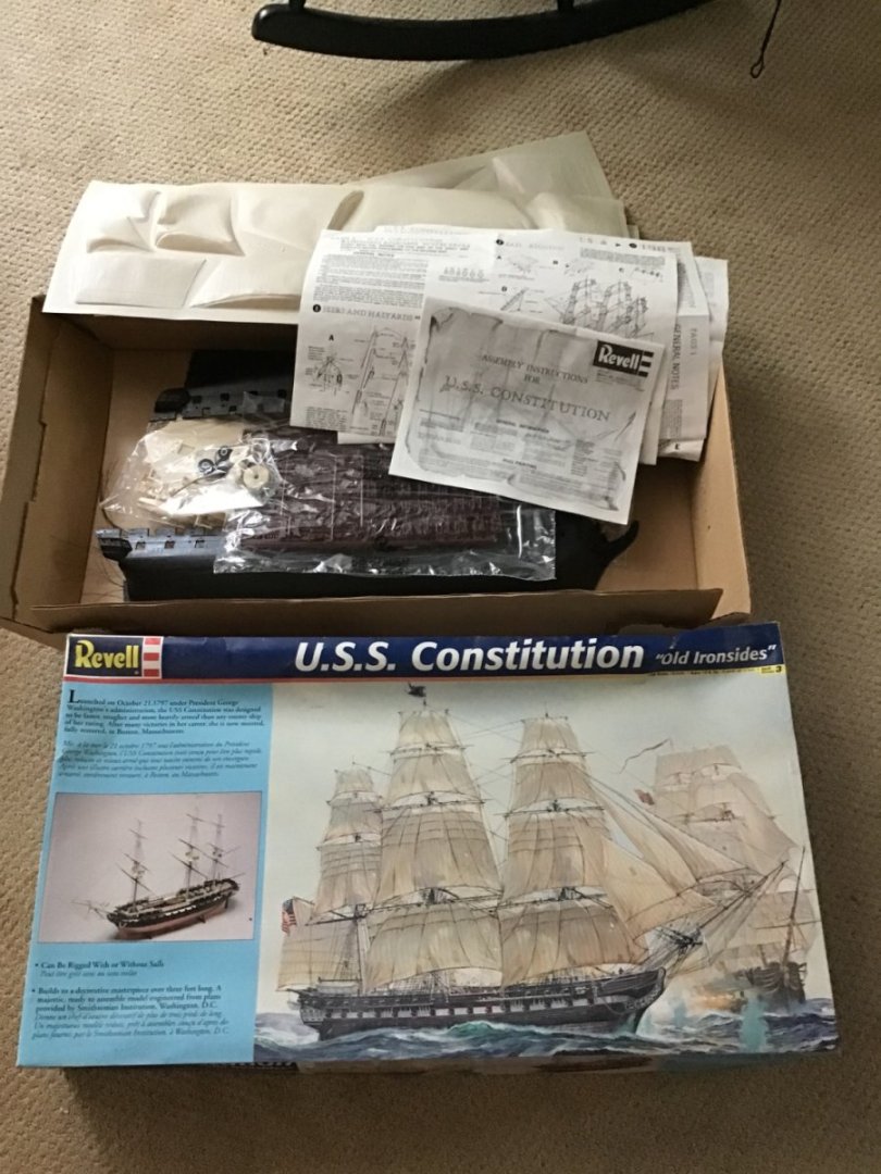
Hi Frank, Are you looking for the Revell, Constitution? I have one, bought it at a local hobby shop, must have been over 10 years ago. Box is intact, never started, bags unopened, vac formed sails, shrouds/ratlines, thread etc. Send me a message if interested. Thanks, -Rich
-
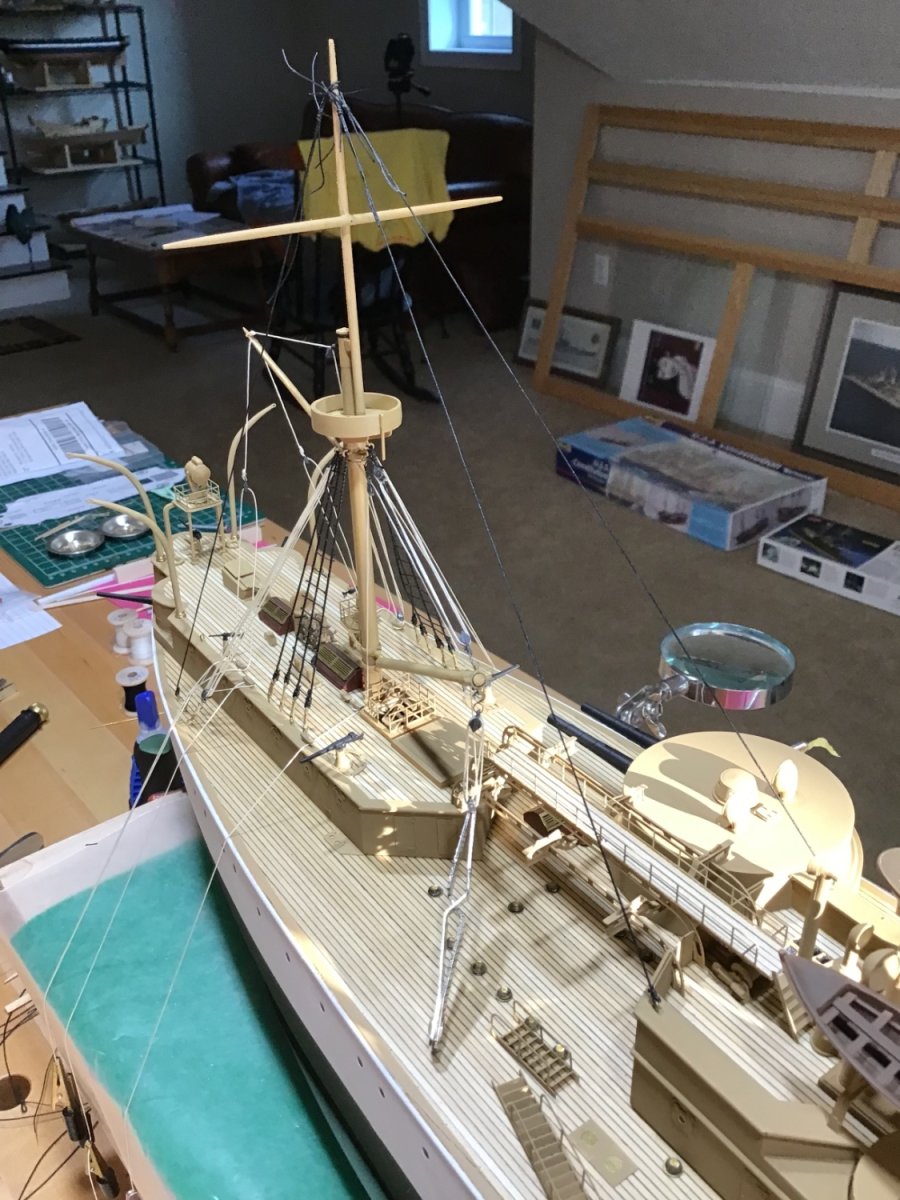
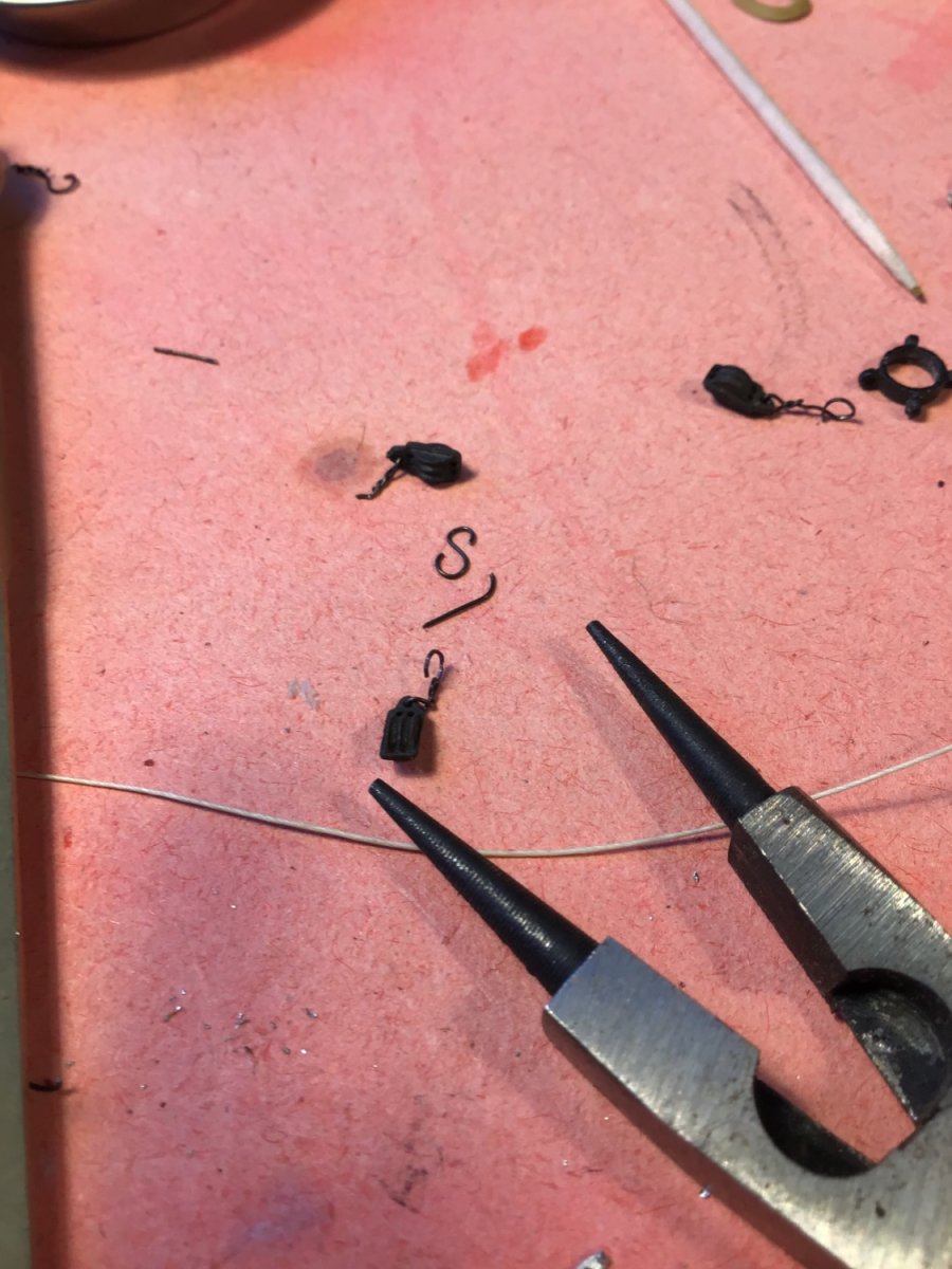
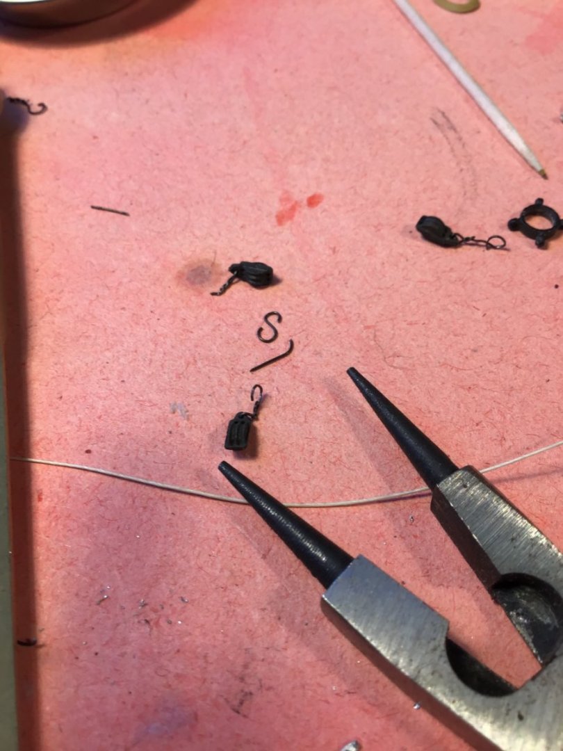
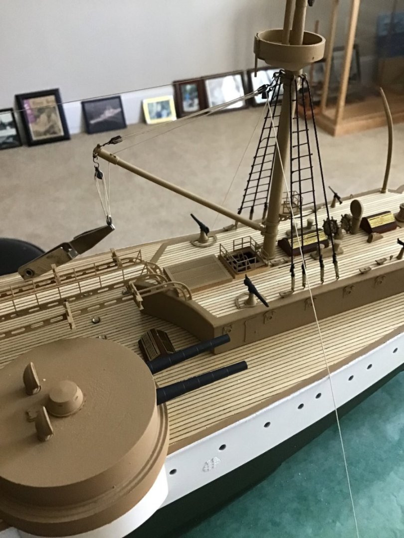
More Rigging Rigged the aft mast derrick with this setup. Then installed it on the ship. The round nose pliers make “S” hooks easy. Foremast rigging is coming along.
- 166 replies
-
- 10
-
-
- Maine
- BlueJacket Shipcrafters
- (and 1 more)
-
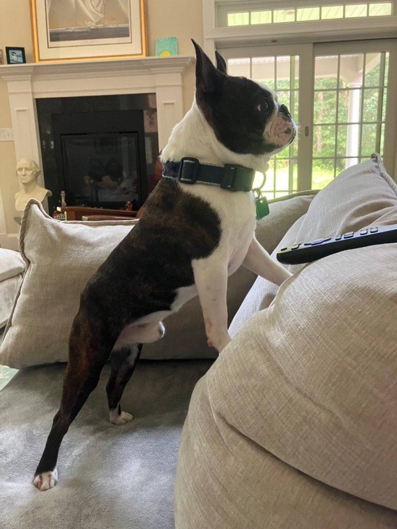
Good Morning, thanks schooner. Annapolis is a place I’d like to go, just haven’t made it yet, we have a new dog, and my wife would go but she isn’t into museums. Looked up “preventer” in a couple of books I have about rigging, nothing there. I’m not an expert on rigging/line names, I’m a mechanical engineer, so from my point of view seems like extra support, maybe because of the “crows nest”, imagine men/weapons up there at battle stations. Getting to the finish line, started last October, hoped for six months. Eager to start something new. A simpler project.
- 166 replies
-
- 5
-
-
- Maine
- BlueJacket Shipcrafters
- (and 1 more)