
ERS Rich
-
Posts
761 -
Joined
-
Last visited
Content Type
Profiles
Forums
Gallery
Events
Everything posted by ERS Rich
-
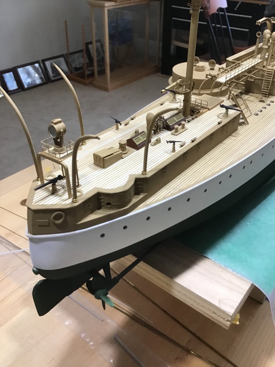
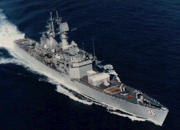
 Anchors Used a round file to make grooves in the deck outboard trim to accept the anchor stanchions (holders). Anchors rest easy in them. Anchors primed and painted white. Second shot shows the start of rigging the ratlines into the turnbuckles, and a ladder that needs to be cut down to size.
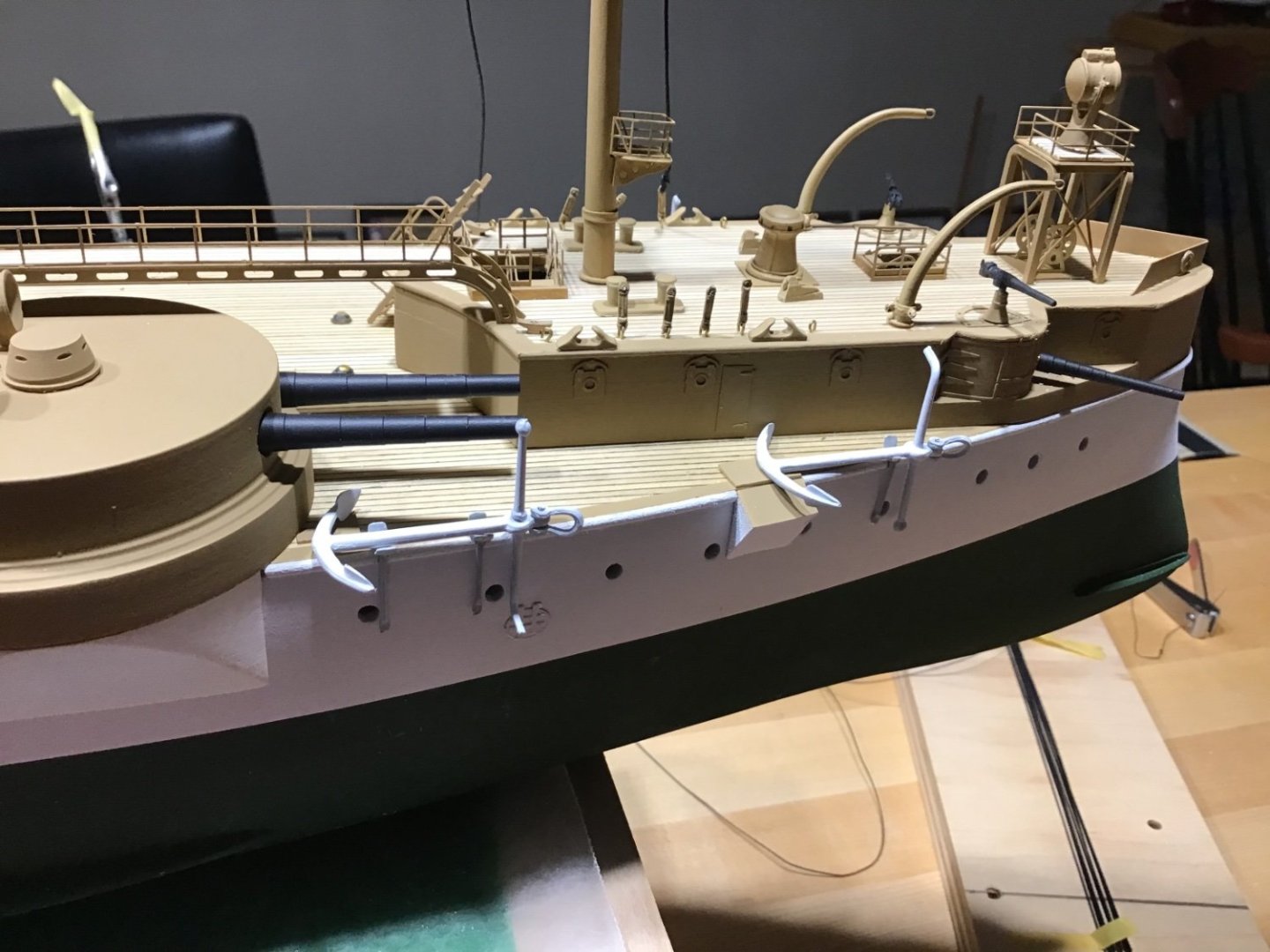
- 166 replies
-
- 9
-

-
- Maine
- BlueJacket Shipcrafters
- (and 1 more)
-
Hello Herby, welcome to model ship world! Always ready to answer any questions.
-
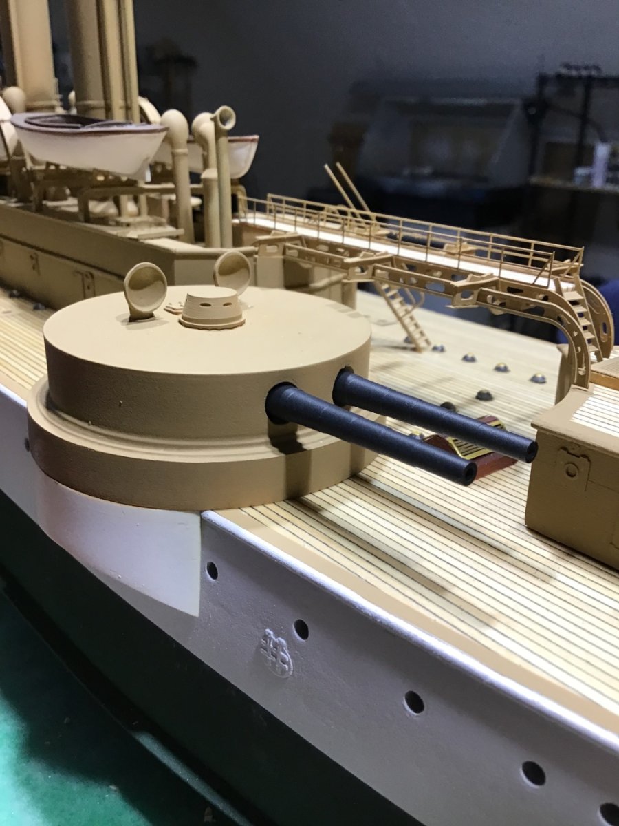
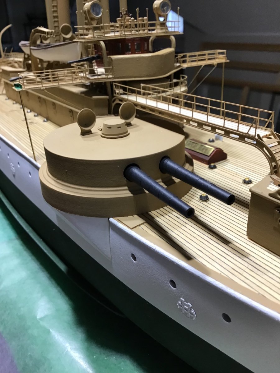
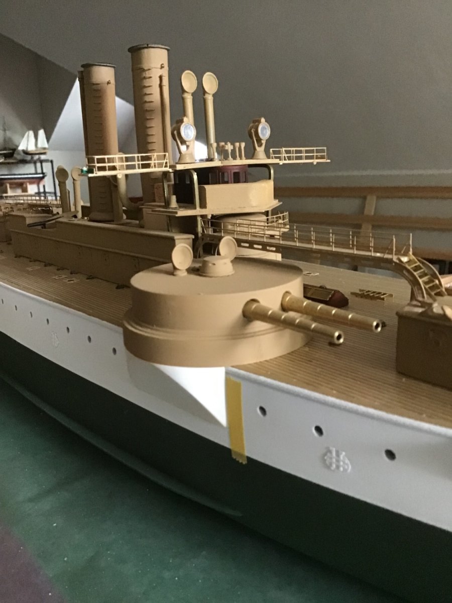
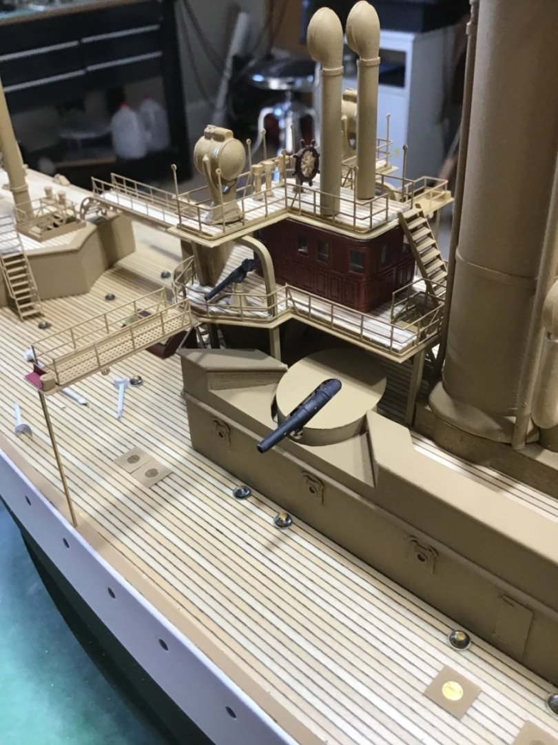
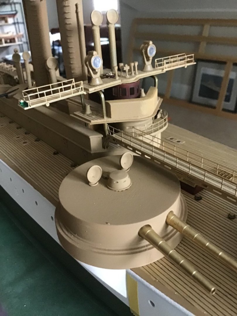
Finishing the Gun Barrels Decided to finish the brass barrels. I wanted a variation from the straight black finish of the smaller guns. Primed brass with Krylon Maxx Grey Primer right out of the rattle can, quick short bursts. Color finish applied with Paasche Talon, #2 tip, air pressure 15 psi. Vallejo Model Air paint, Black 71.057, 15 drops in the cup, then 1 drop Gunmetal 71.072, and stir well. Finish with thin coats of Valejo Matt Varnish.


- 166 replies
-
- 11
-
-
- Maine
- BlueJacket Shipcrafters
- (and 1 more)
-
Thanks Ives. It’s hard to describe. Words like detail and intricate are trite. Often spend time looking at the model and friends and family love it. (My wife wants me to sell it. Can’t get there.) It may be the combination of materials: wood and metal, and the shapes: angles and curves of the superstructures, railings, round turrets. And it’s interesting that this iron ship has masts with the round tubs. Anyway it’s a fine kit with plenty of material. And certainly worth the effort. Sometimes I think, how did I make this? Did I do all of this? My approach to the work is just thinking of the next step, because thinking of all the steps at once can be overwhelming. Getting to this skill point has been an over 10 year journey, that started when I was working full time. I work part time now and I’m very fortunate to have the space for a nice shop. And the time to figure out how to do the work. After many models, and now Maine, I have most of the process figured out. Except maybe primer on brass, still have an adhesion problem. Not sure what’s next, plenty in the stash. Probably some plastic for a break. Faster and helps building finishing skills. It may be another power vessel, I have a Tug, the Nantucket Light Ship, and Olympia. Also USS California, my alma mater, by Ironshipwrights. Thanks for listening. -Rich
- 166 replies
-
- 5
-
-
- Maine
- BlueJacket Shipcrafters
- (and 1 more)
-
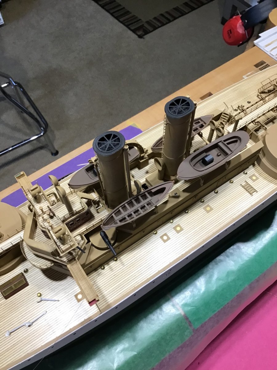
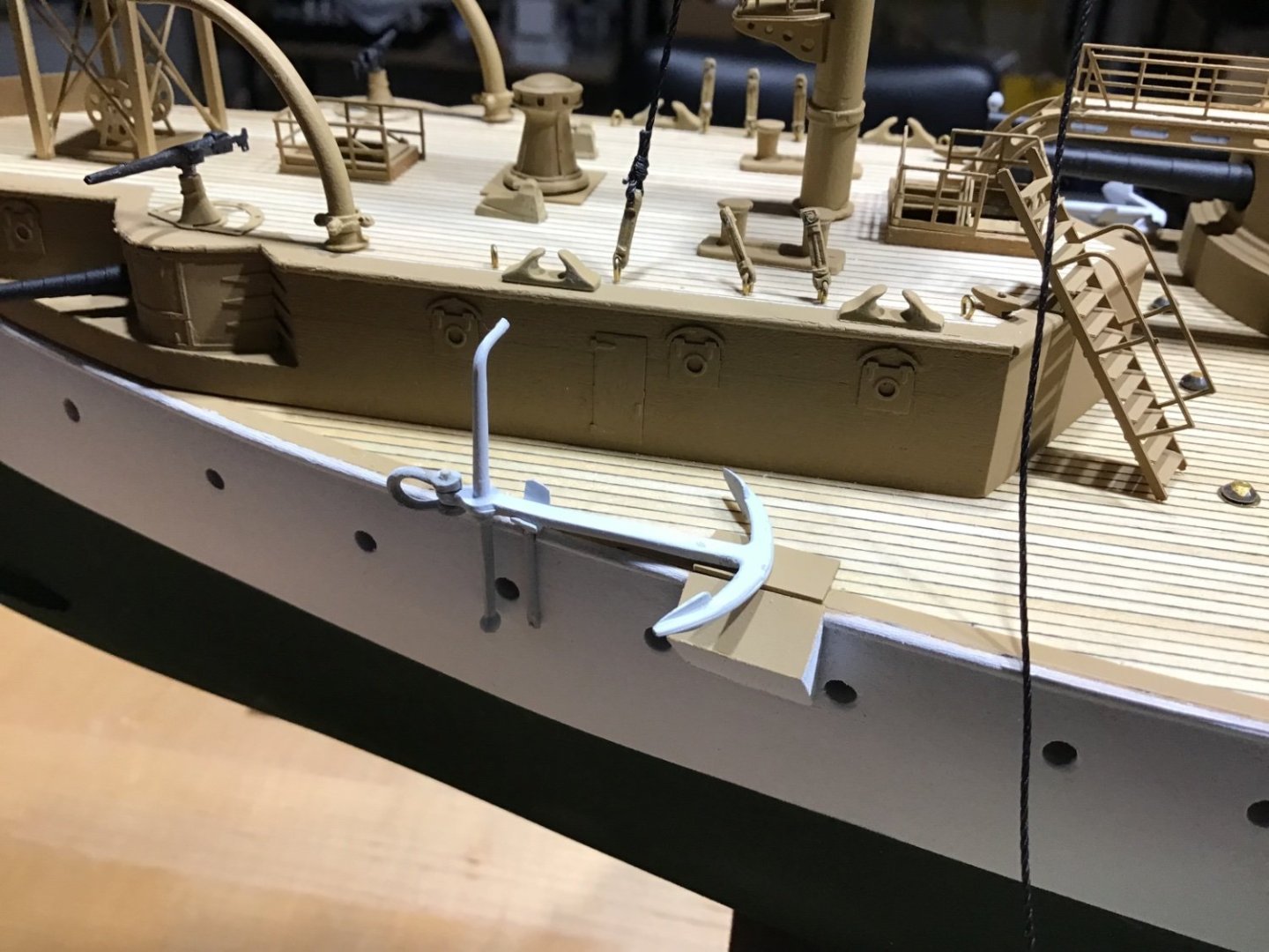
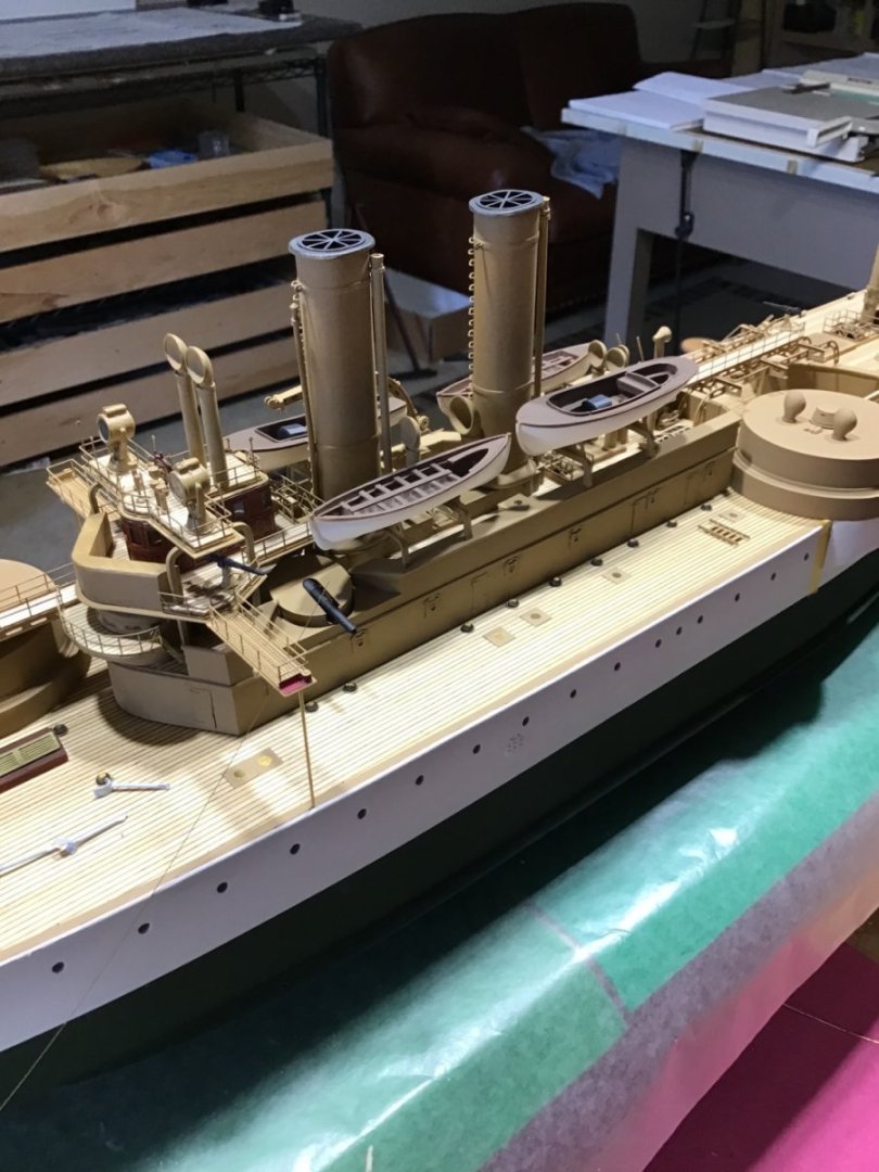
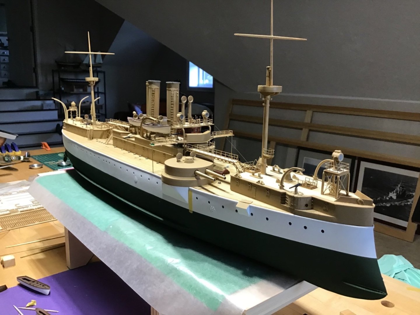
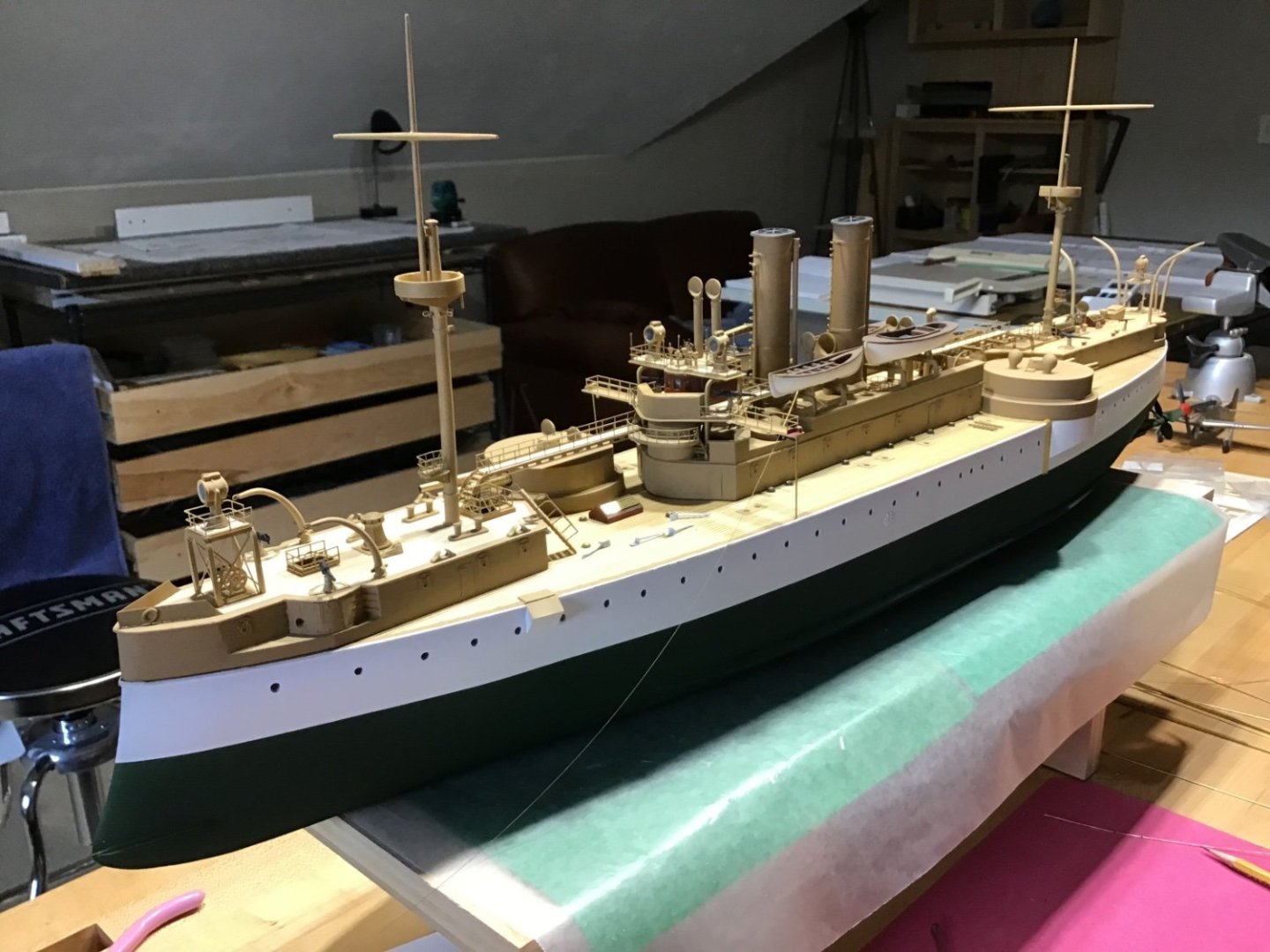
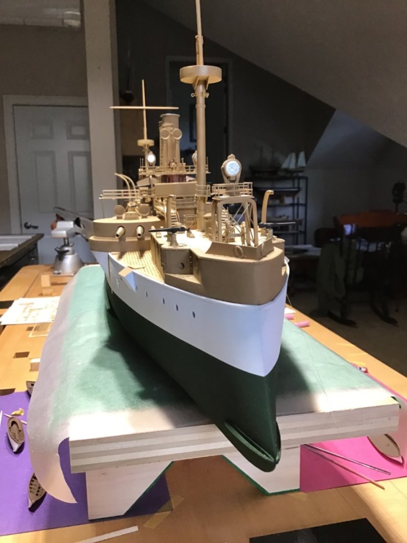
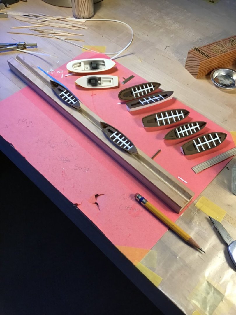
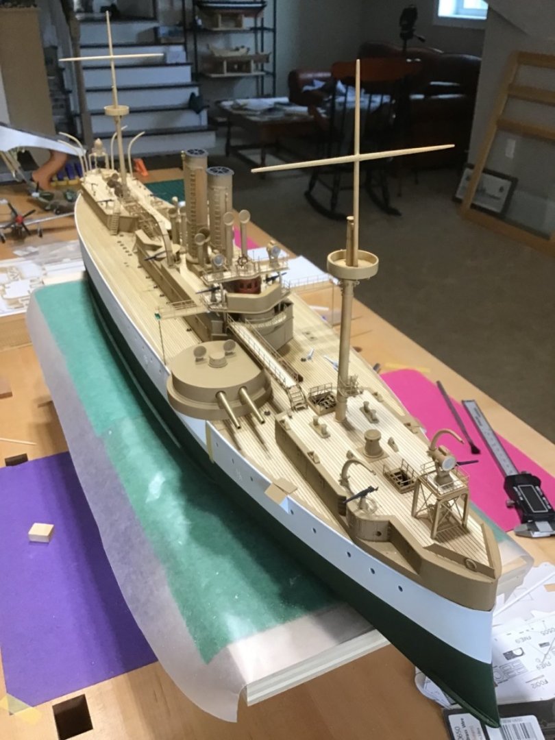
Locating Ship’s Boats Amidships At this point each assembly steps feels like an added layer of complex detail, which makes the ship comes to life. Boat skids are installed. Dry fit the boats on the skids to determine the cradle locations on the skids, then installed the cradles and painted. View of boats from port, starboard, and overhead. Plus a few shots of the model, masts dry fitted.

- 166 replies
-
- 13
-
-

-
- Maine
- BlueJacket Shipcrafters
- (and 1 more)
-
Ship’s Boats Finished with Tamiya Flat White XF-2, and Vallejo Medium Brown 71.038. The boilers in the launches are Vallejo Black 71.057 with a few drops of Gun Metal 71.072 Eagle Talon airbrush, #1 nozzle and tip. Straight paint, no thinner, 20 psi. Strip stock from the kit.
- 166 replies
-
- 11
-
-
-
- Maine
- BlueJacket Shipcrafters
- (and 1 more)
-
Back in the office. Fresh eyes, fresh perspective. Interesting how the model looks better after a break, see the whole ship, rather than just, what could be done better.
- 166 replies
-
- 4
-
-
- Maine
- BlueJacket Shipcrafters
- (and 1 more)
-
Thank you for showing how this work is done. Inspirational!
-
Wow, that’s amazing, thanks for posting.
-
Hello Bill, greetings from Central Mass. Always around if you need a hand.
-
Will you continue with the Puritan? The hull looks ok. Completion of any ship is a huge step. Checkout Tom Lauria’s channel on YouTube. He recently posted videos of how he restored a ship, Emma C Berry, built from a kit that may be similar to yours. Tom is an awesome mentor, his videos show how to do the work in simple practical ways. Find and study with the masters, they are here, the people doing the work, not just talking about it. Lookup Mr. Kevin Kennedy. @Kevin Kenny Next steps? Learn how to sharpen a chisel and your tools. Grab the book, https://www.amazon.com/Ship-Modeling-Simplified-Techniques-Construction/dp/0071558675. Tips and techniques useful when building any ship. Look at Model Shipways, Armed Virginia Sloop and the practicum by Bob Hunt. https://www.lauckstreetshipyard.com/product-page/armed-virginia-sloop This practicum is remarkable, Bob shows how to rig every line. And the kit is a larger scale and easy on older eyes. Best
-
Hello Antonio and welcome to the World of Model Ships. Kits and Scratch building? Scratch build an entire ship. Add scratch built components to a kit. Every wood kit, even the simplest, requires skills used in scratch building. Wood model shipbuilding, scratch or kit, is using a plan, and measuring, marking the wood, and removing the waste with a tool. A saw, a rasp, a knife, a chisel, a file. Kits save time by providing pre shaped parts, that even so, typically must be worked to final shape, and the wood stock: dowels that must be shaped into masts and spars, strip wood that must be cut into planks that must be spilled and tapered. What you do in your “shipyard” is up to you. Like a real shipyard, your yard is an assembly point, which components come from kits (vendors in real life) or are scratch built by you (fabricated by the yard in real life) is up to you. A motto here is better modeling through research. The plan and the research bound creative imagination. Real creativity or imagination, is needed to devise ways to accomplish the work, to use tools and paint to transform a log, or a pile of wood components and stock, into a convincing rendering of the ship. It’s all about skill and execution, in the end kit or scratch build doesn’t matter. All the best.
-
On vacation, resume in about 2 weeks. Up ahead is ship’s boats, anchors, rigging, and the case. Hope your summer is relaxing where you are…..
- 166 replies
-
- 5
-
-
- Maine
- BlueJacket Shipcrafters
- (and 1 more)
-
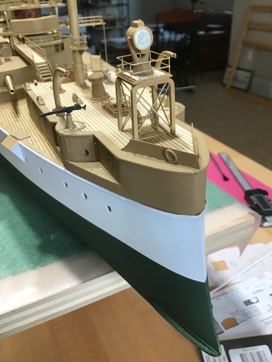
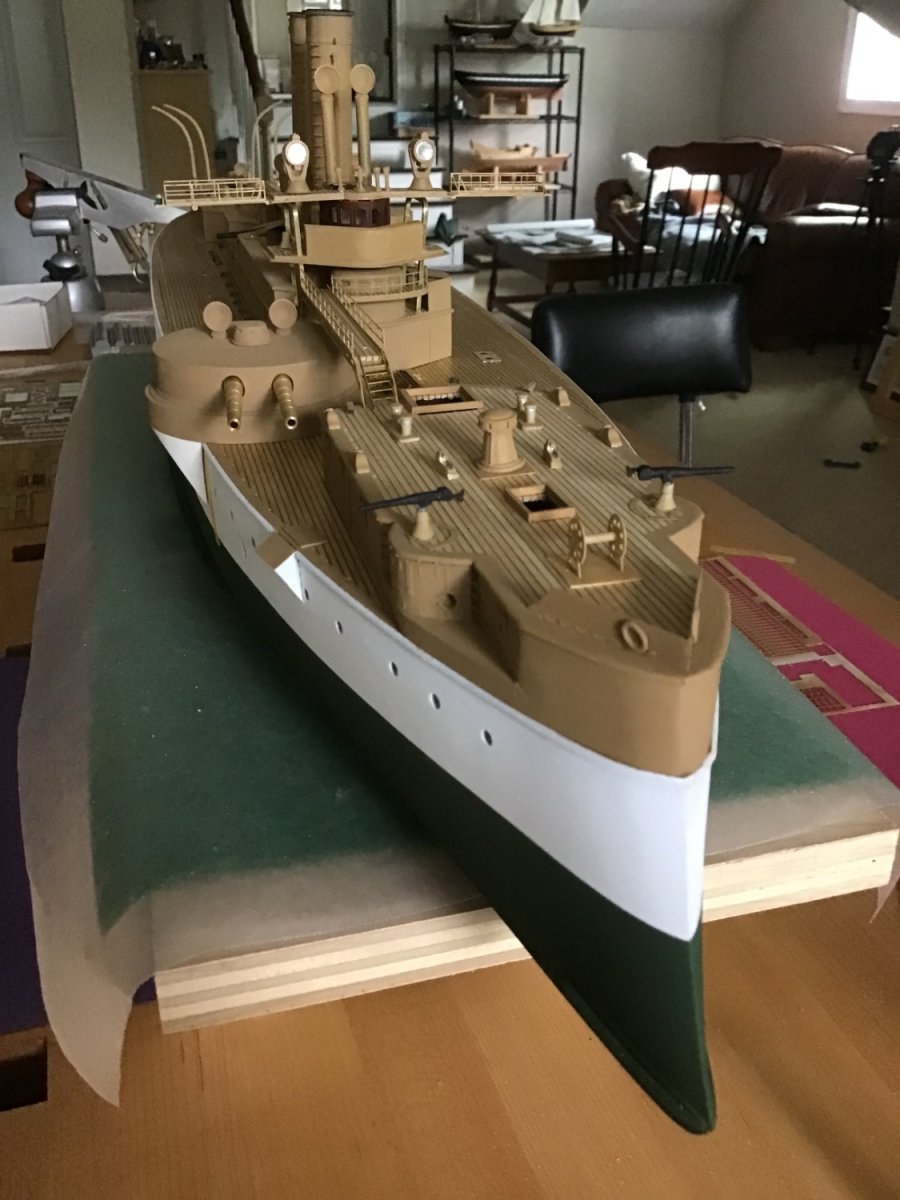
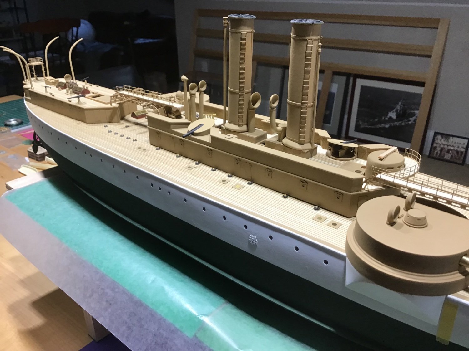
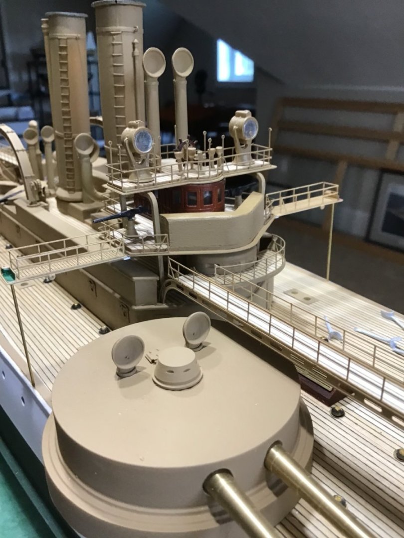
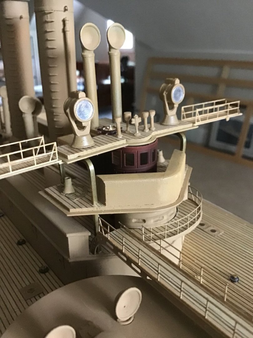
Progress Photos Finally completed the superstructure. Painted the Pilot House a second time, a lighter shape of Vallejo Mahogany over a white base coat, followed by light coats of Vallejo Gloss varnish. Sheet styrene for the windows.


- 166 replies
-
- 10
-
-
-
- Maine
- BlueJacket Shipcrafters
- (and 1 more)
-
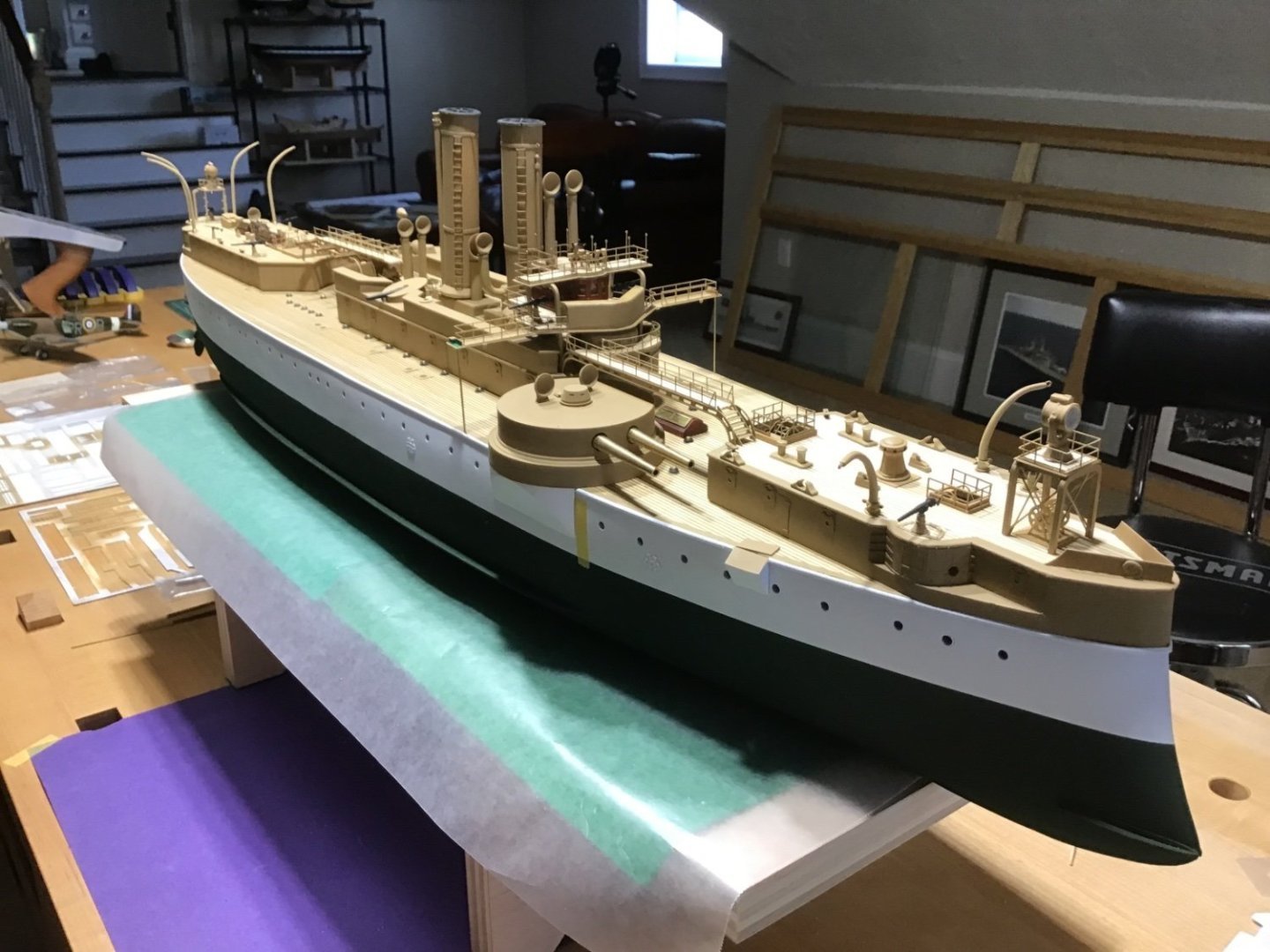
Progress Photo Have been telling myself “next week it will be done”, for about the last six weeks. Itching to start something new…. Here is where we are. Notice the bridge wings were installed off the wrong deck, they were higher off the Flying Bridge, now relocated off the navigation deck… Brass frets just about empty, running out of parts to install, it’s all about the journey…..
- 166 replies
-
- 9
-
-
-
- Maine
- BlueJacket Shipcrafters
- (and 1 more)
-
Hi Nic, could you share a few thoughts on how to get the foot ropes to lay so easy? They look just right…. Thanks
- 121 replies
-
- 1
-
-
- Newsboy
- Model Shipways
- (and 2 more)
-
Cutty Sark main flag hoisting and rigging
ERS Rich replied to Bruma's topic in Masting, rigging and sails
My interpretation of the illustration is a single line attached slightly above the pole midpoint, passed through a block, to raise the pole, then, not shown, a single line attached to the pole bottom for tension. Cheers! -
Welcome to Model Ship World!
-
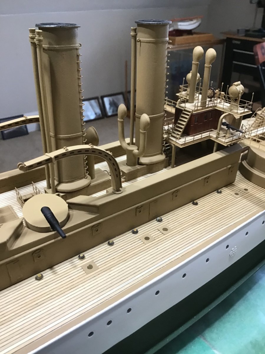
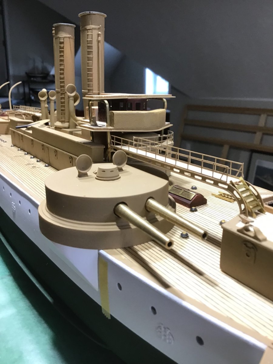
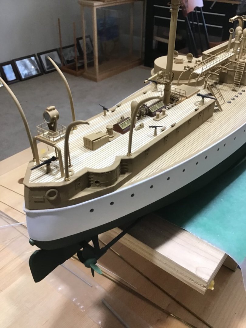
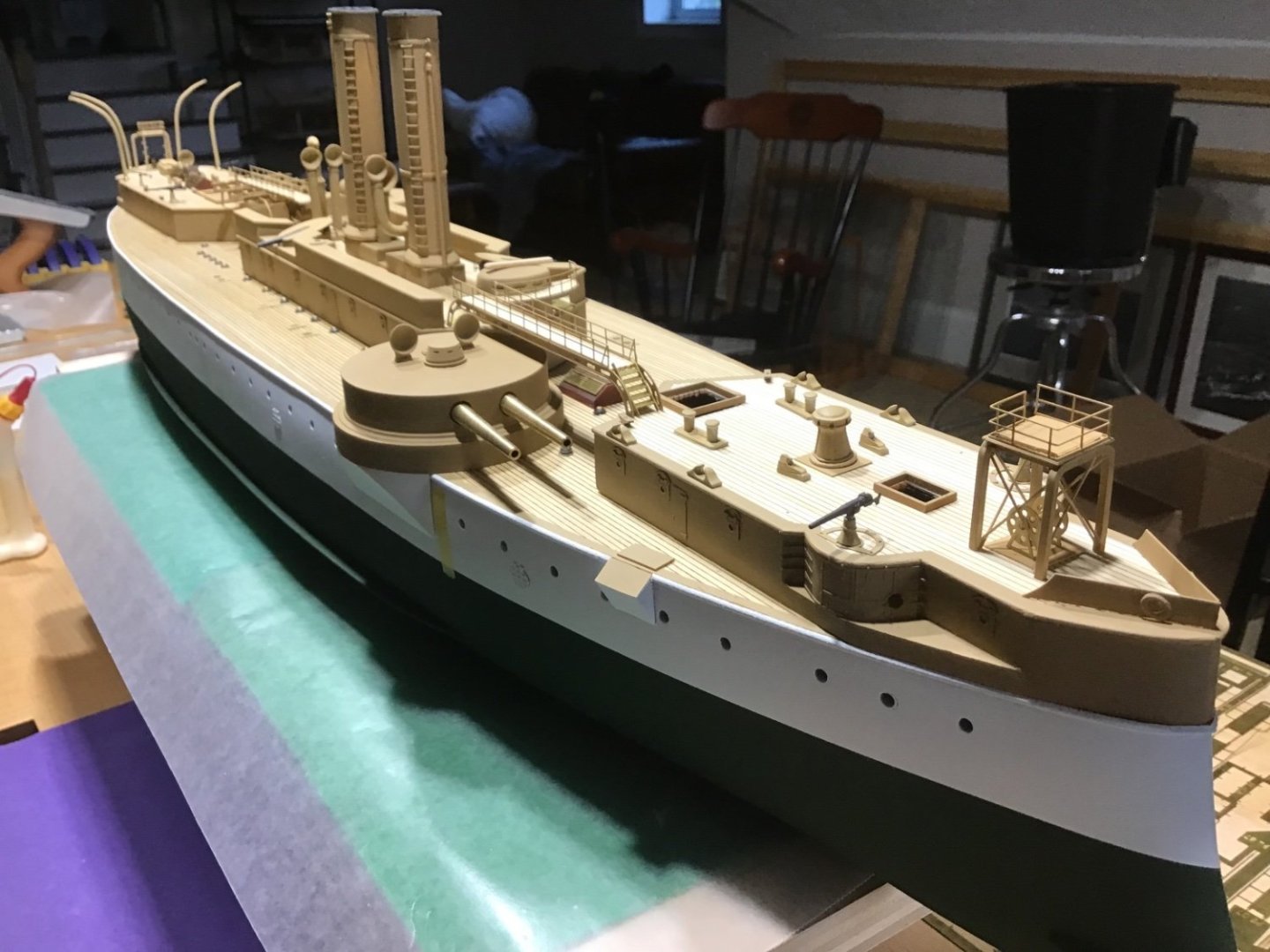
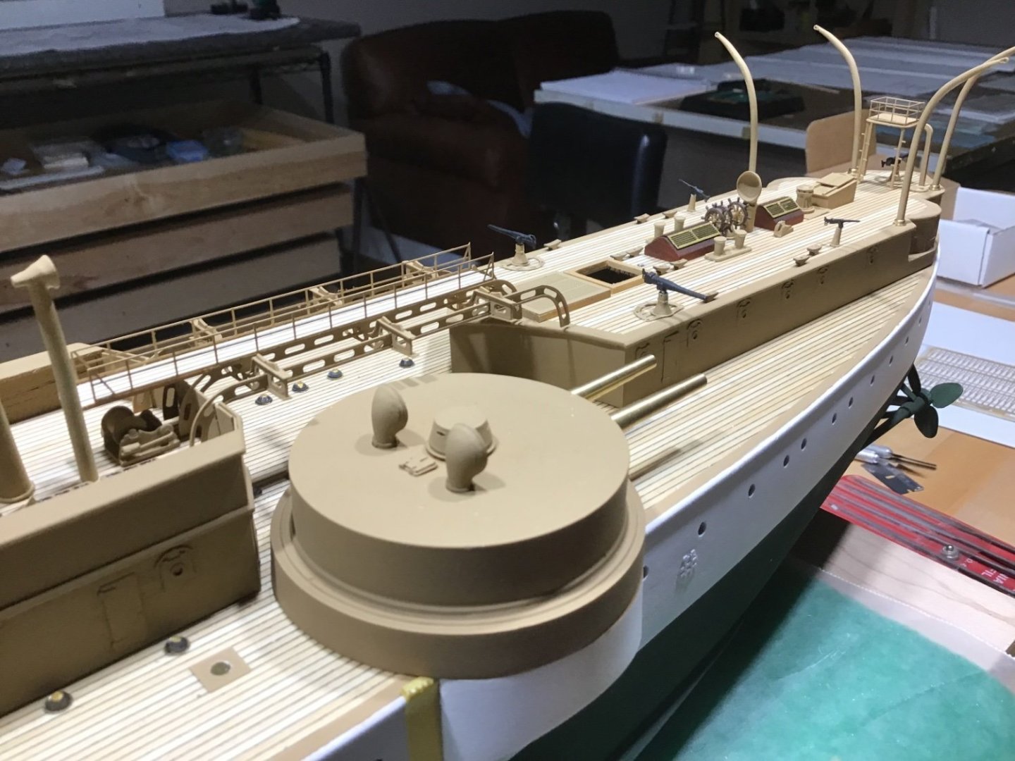
Close Ups Dry fitting, adjusting, painting the details, working towards the superstructure glue up. Debating about the big gun barrels, leave brass, or paint black, probably black…. I just love the character of this ship!


- 166 replies
-
- 9
-
-
-
- Maine
- BlueJacket Shipcrafters
- (and 1 more)
-
Welcome! Always available to answer a question. -Rich
-
Thanks for joining, appreciate your kind words, and will keep the updates coming. Cheers!
- 166 replies
-
- 3
-
-
- Maine
- BlueJacket Shipcrafters
- (and 1 more)
-
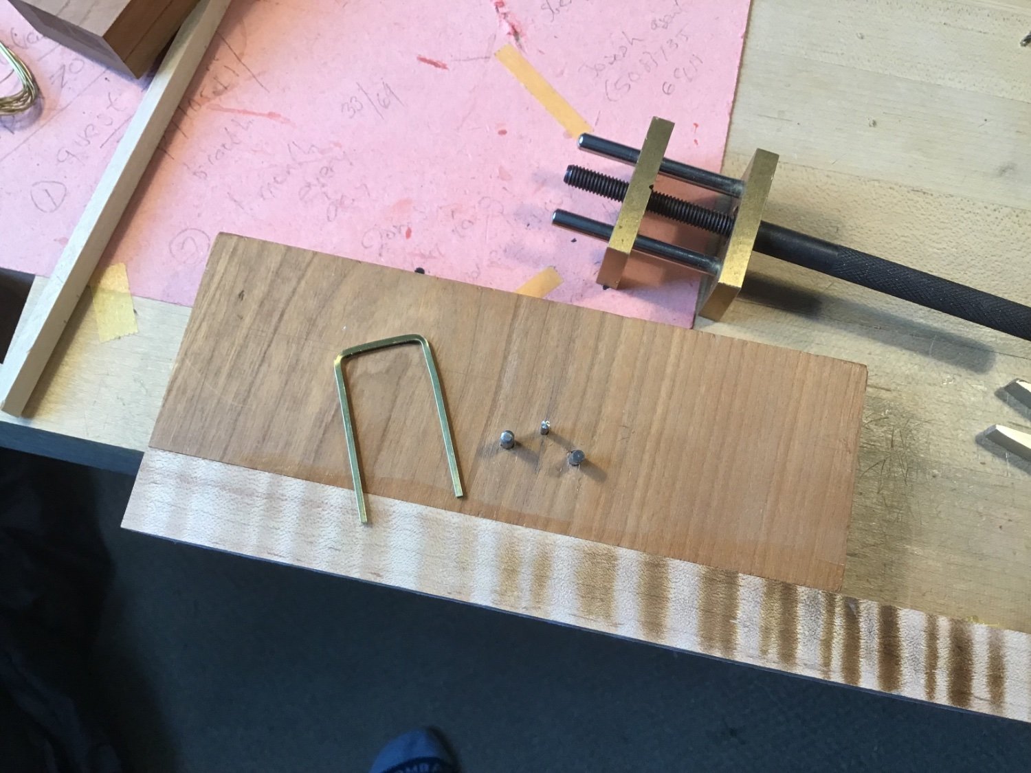
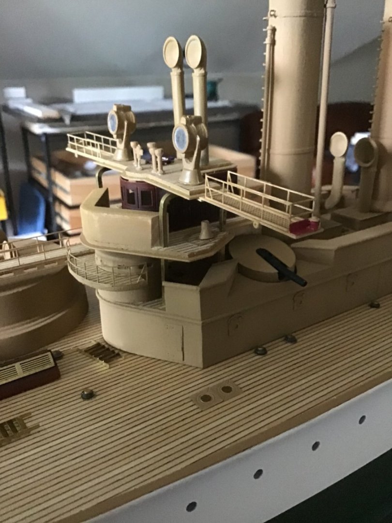
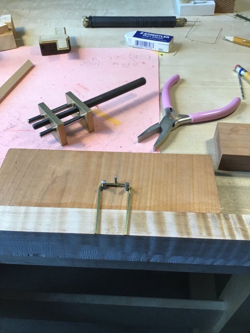
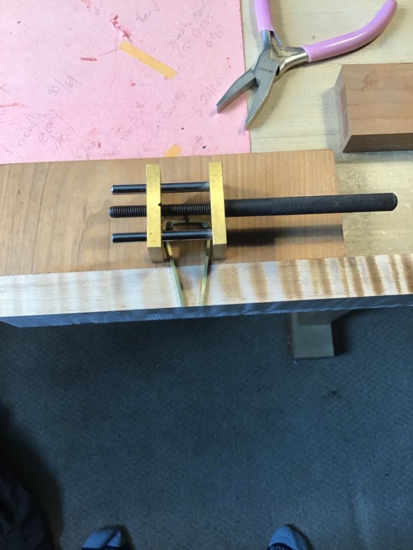
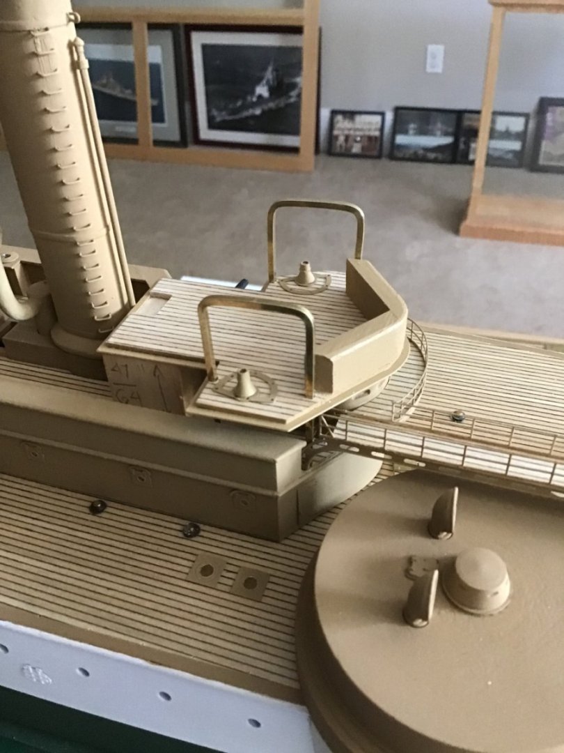
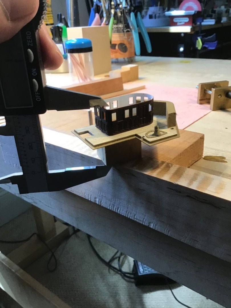
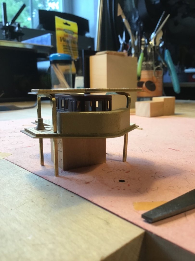
Flying Bridge Supports Had to give this some thought as these supports need to fit exactly through square holes in the Navigation Bridge. Precise bends are required. The supports are 1/16” brass rod. Note my first attempt was not successful and needed more bar stock. Called Bluejacket and the crew helped and sent out additional stock right away for a reasonable charge. Decided to make a jig, shown below. The instructions call for 1/8” radius bends. So measured the inside spacing of the square holes in the Navigation Bridge, and drilled 1/8” holes in the board so the distance between the outside edges of the bits correspond to the measurement - 25/32”. Also installed a third bit, to minimize the upward bow, midway between the 1/8” bits. Make a mark on the piece to bisect it’s length, and register the mark on the middle bit, to help get even legs. I used the vise (available at Micromark) to make sure the bar as fully wrapped around the 1/8” bits. Dry fit…. Stacked up the superstructure to get an idea of the leg length. First pass, about a 1/16” gap between the pilot house roof and the flying bridge deck. Used wire cutters to take a nibble off the legs. Evened up the legs with the Ultimation disk sander and a file. Dry fit on the model….


- 166 replies
-
- 7
-
-
- Maine
- BlueJacket Shipcrafters
- (and 1 more)
-
Thank you Rick, tried to gear the information to show that ship modeling is doable. Cheers!
- 166 replies
-
- 3
-
-
- Maine
- BlueJacket Shipcrafters
- (and 1 more)
-
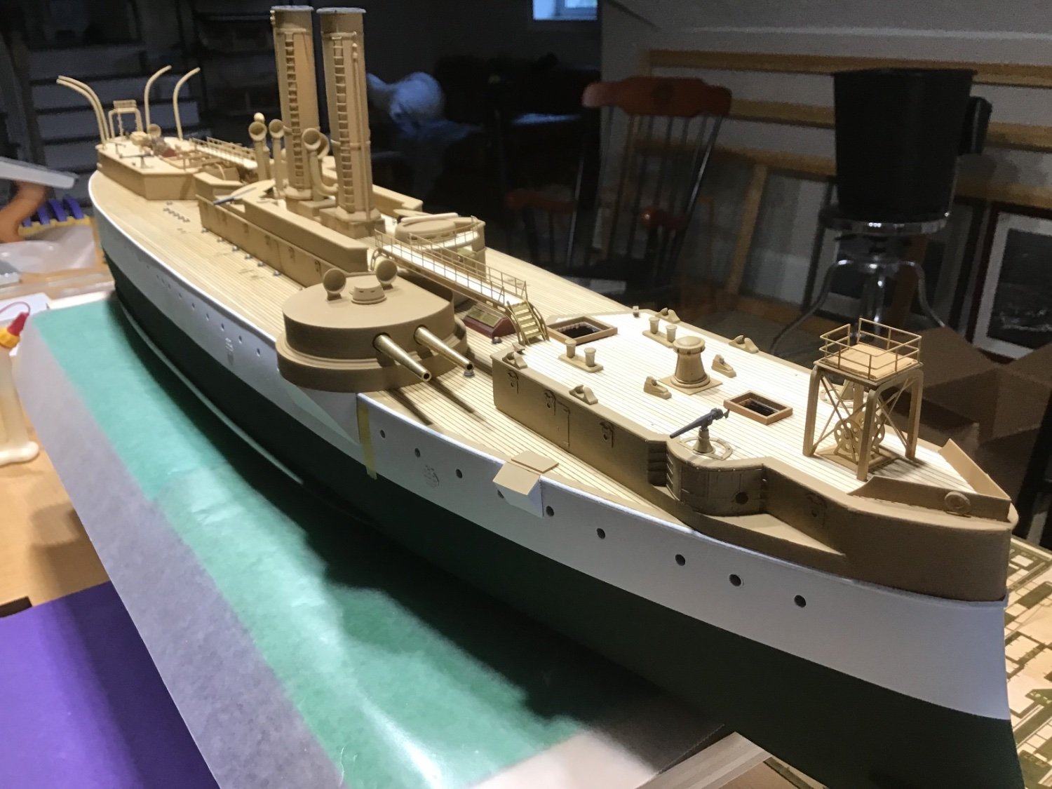
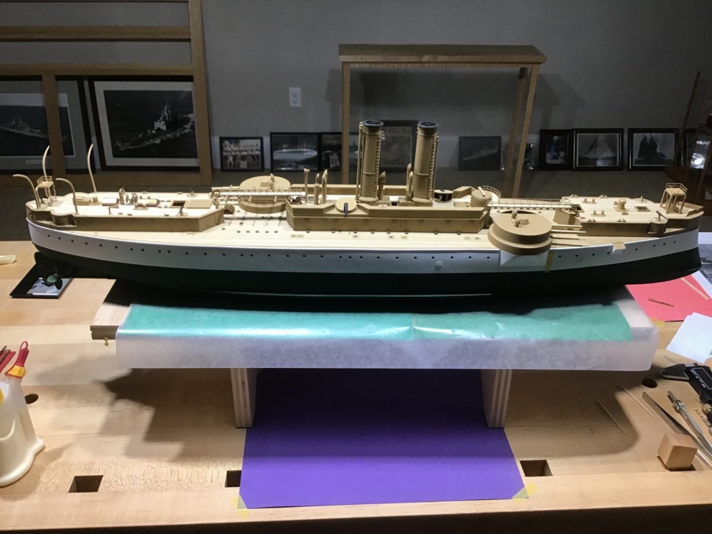
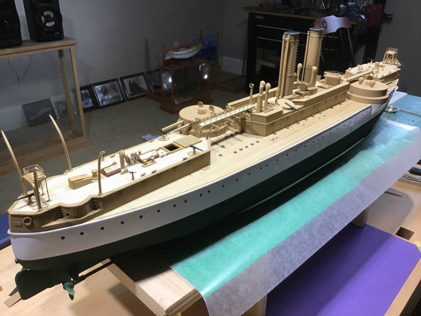
Progress Photos Almost in the home stretch. Navigation and Flying Bridge assembly are major bits left….

- 166 replies
-
- 9
-
-
-
- Maine
- BlueJacket Shipcrafters
- (and 1 more)