bobandlucy
-
Posts
512 -
Joined
-
Last visited
Content Type
Profiles
Forums
Gallery
Events
Everything posted by bobandlucy
-
 Great job! I'm just about to begin planking and am a little apprehensive. Yours looks great, and it's nice to see the corrections you've made working out so well. Bob
 -
Thanks, Iraymo. I would not call my models perfect by any measure, but if the logs help you I am pleased! I am very slow at this, and as Spring is here I have yardwork and fishing to do, so I will probably still be here, inching along when you get to this model. . . Bob
-
Thanks, David! Do feel free to point out any flaws. . .
- 52 replies
-
- 1
-

-
- Model Shipways
- muscongus bay lobster smack
- (and 1 more)
-
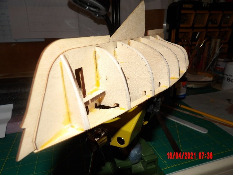
Thanks, Gregg! Yes, I did paint the seats and floor Warm White before adding the deck, and after studying the coaming piece it became apparent what the notches in the frames and the slots on the deck were for. I do appreciate the heads up. I puzzled over this for quite a while. . . I had some mismatch of the deck halves in the aft section, and used some filler to try and correct. I will add some wood dust/glue filler along the rest of the deck joint. There is a little warping of the deck adjacent to the cabin wall frame, I will try some automotive body filler there, but I will wait until placing the cabin door assembly, because it seems that will reveal just how much material needs to be added. Used yellow glue to add reinforcement fillets, because it would not show in the completed model, and I wanted to see where I might use this glue, rather than white, in the future. I think I would prefer the white for most things. . . I began the fairing and really taking my time with it over several days, as I find that if I do it too long I will tend to rush (also made the switch to decaf coffee!). I had some frames that protruded beyond the deck edge, and carefully used a Dremel flap sanding wheel to take these down somewhat, leaving enough material for fairing. I was really in the dark as to how the bottom part of the transom was to be shaped, until it dawned on me that it should be part of the fairing process, so more work to do there. I'm really getting a feel for the fairing, as David A. says in the manual, a light touch works best. One can feel the shape smoothing out. I'm enjoying this part more than I thought I would. Still a ways to go, but here are pics of progress.
- 52 replies
-
- 2
-
-
- Model Shipways
- muscongus bay lobster smack
- (and 1 more)
-
Your model is looking good. I also built this model. Interesting glue discussion. I've been using white PVA and sometimes a little CA, but I think I'll try yellow when I start planking my current model. Read the instructions carefully! Good methods are given there, but you must think ahead and understand what is intended. When you find yourself asking, "why is this piece shaped this way, what is this notch for," it's time to stop and think. When I have continued to assemble without understanding, that's when I've made mistakes which would have been easier to correct before adding the piece. I also tend to start to rush a bit at the point where the model really starts to look like a boat, that's a dangerous time for me. . . I'm learning to slow down (slowly!). Just some free advice from another beginner as I'm sure I'm not unique, take it for what it's worth. Bob
- 85 replies
-
- 4
-
-
- Lowell Grand Banks Dory
- First Build
- (and 2 more)
-
Just beautiful, inside and out! Your wife is very talented also. Bob
- 79 replies
-
- 2
-
-
- Fifie
- Victory Models
- (and 1 more)
-
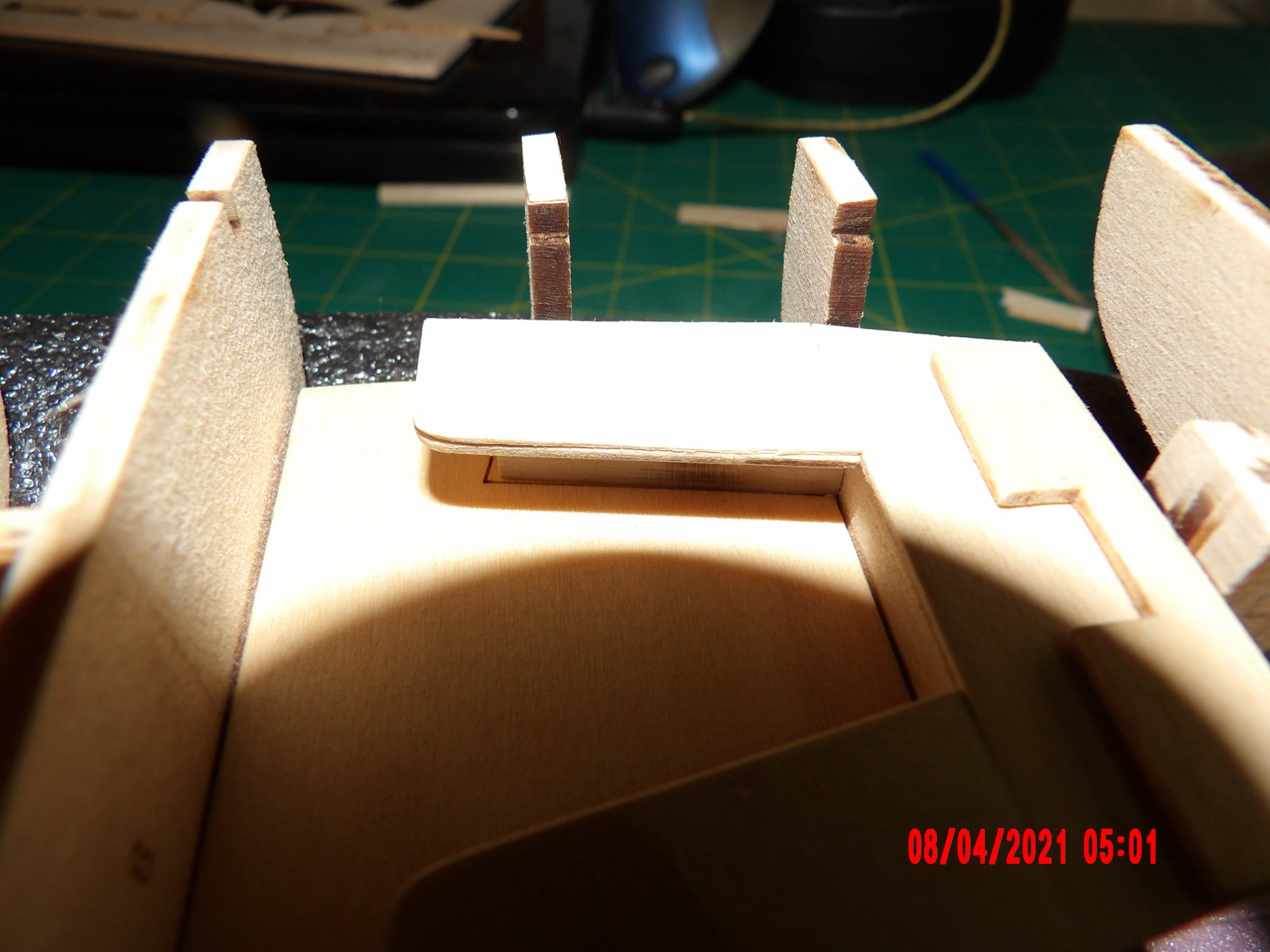
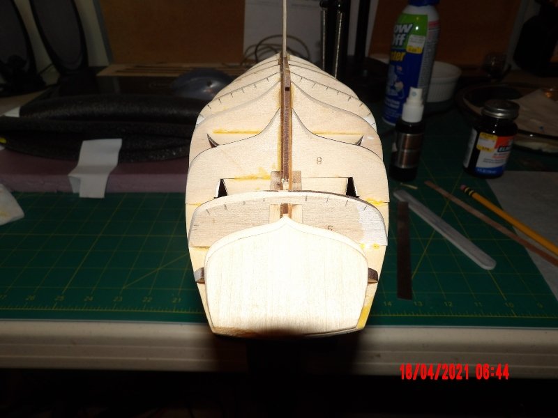
I did some light fairing on the tops of the frames and dry fitting of the deck pieces- one frame was revealed to be low on one side. I added a shim piece to the top of that frame. The top of the transom was way too tall and I did some surgery and sanding to reduce it. I took a little too much off, but the forward half of the transom is fine after fairing and where it should be. Since the back edge gets sanded to vertical later I don't think this will be a problem. I don't know how it happened, but the slot for the transom pivot rod was obscured at the top and would not accept a 1/16" rod. I took a drill bit and opened it up. The restored path was not exactly parallel to the stern post, but not too far off, and I will be able to correct by wallowing a broach a bit in the hole. The frame (No. 9) adjacent was very loose when fitting to the spine and I made and added shims at all four contact points. At the top the shim needed was so small it was impossible to place, so I inserted long pieces and then cut them off. The area of the hole and the reinforcement pieces protrudes above the cutout window in the seat back- I don't think this is right as it will cause interference between the tiller and the coaming, so I will sand it down level to the bottom of the window. Installed the seat bottoms and did not notice that one of the side seats sat below the level of the back seats. I took my scalpel and made a "veneer" piece and glued it on. This seemed to me the best solution (actually, the best solution would have been to remove the offending piece, and adding shim to the top of the seat support), although the thickness of the seats is now different, it is better than the shadow cast by the offset at the junction of the two seats without the veneer. Since I had rounded the edge of the seat, there is now a line when viewed edgewise, but I can correct this by adding some wood dust/glue filler. Honestly, if I had adhered to the instructions, this would not have occurred at all. State of things overall below. I'm a little embarrassed to go into all this detail, as it would bore an experienced builder- but I really want this log to be of value to other beginners tackling this model.


- 52 replies
-
- 3
-
-
- Model Shipways
- muscongus bay lobster smack
- (and 1 more)
-
Thanks, Bob. I already finished the Pram, and am now working on the Lobster Smack.
- 38 replies
-
- 1
-
-
- First Build
- Model Shipways
- (and 2 more)
-
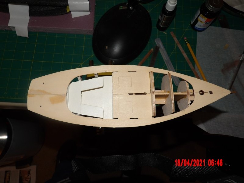
Awesome, good lines as seen from above- better than mine. Isn't this fun? bob
-
Iraymo, thank you. I started this model several months into my retirement. Retirement is great! This is a learning series, and the techniques taught outweigh in value whatever results you may achieve. One thing I have learned since retirement from a very demanding, exacting occupation is that now, there are no inspectors, no bosses- it's just me having fun. The people here are not judgmental and have helped me a lot. Bob
- 38 replies
-
- 1
-
-
- First Build
- Model Shipways
- (and 2 more)
-
Absolutely, Will. I don't want valleys to form and surprise me. . . Thanks for your interest in my building! Bob
- 52 replies
-
- 1
-
-
- Model Shipways
- muscongus bay lobster smack
- (and 1 more)
-
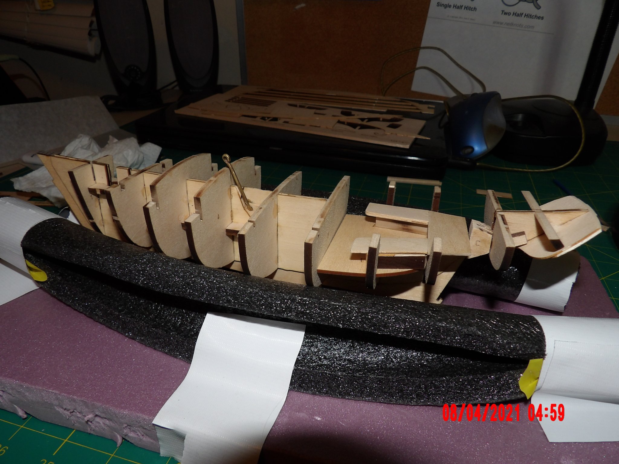
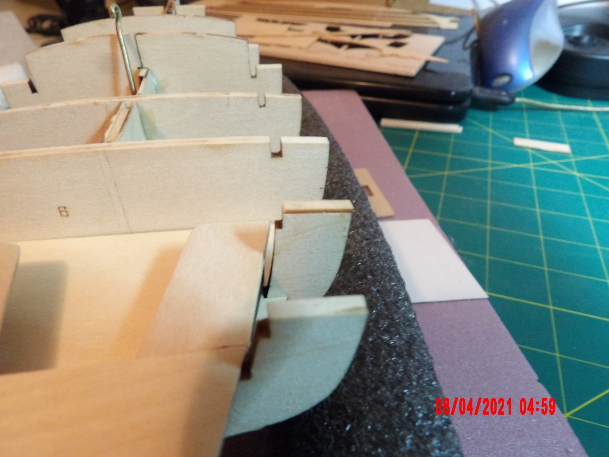
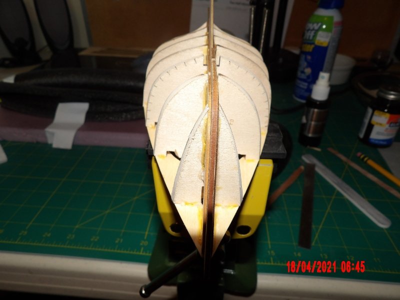
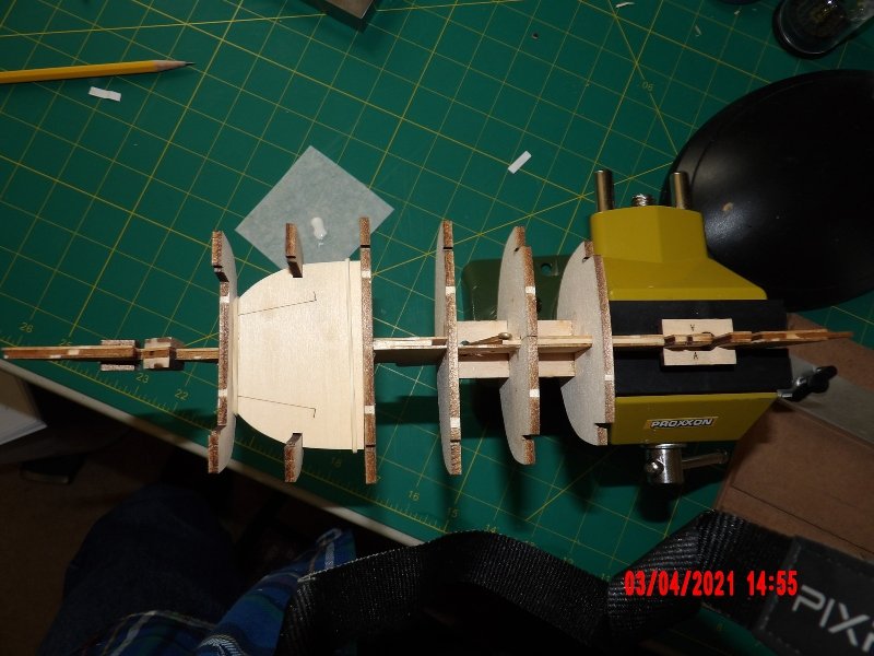
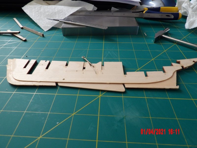
Kept going and installed more frames. I did remove the char from the slots connecting frames to spine, but neglected to think about the top side. I'll have to clean that up in place as I go, as I did before gluing in the cockpit floor. That seemed like a good place to stop for the day. I'm really pleased that the spine looks to remain straight and the frames are squarely set in the spine. Everything looks symmetrical and hopefully the fairing will be made easier and smooth. I was careful to check each as I went, and where the frames should be flush with the spine, they are, with only small error.
- 52 replies
-
- 3
-
-
- Model Shipways
- muscongus bay lobster smack
- (and 1 more)
-
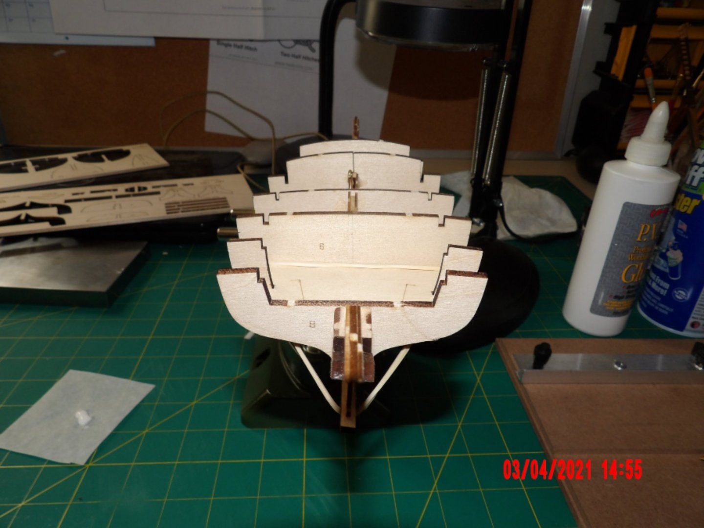
Today I put in Frames 3, 4, and 5. It turns out that Frame 3 had a notch pre-cut on both sides that would have contained the centerboard pivot point rod so the rivet would not have been necessary if assembled correctly. However, on my model the rod is just to one side of the frame, and so might have fallen out over time. The centerboard still has full travel after adding the frames. I only had to shim one half of the two-part Frame 4. I am using white glue on the frames, but as you can see I'm also adding CA glue here and there for insurance.
- 52 replies
-
- 3
-
-
- Model Shipways
- muscongus bay lobster smack
- (and 1 more)
-
Thanks, Will- for the offer of help. I most certainly will need it! I was flying high with the completion of the sailing pram, which came out pretty good, I think. Like I said, I'm being humbled now. But my attitude is good. I did not even swear much when I broke the spine! Bob
- 52 replies
-
- 1
-
-
- Model Shipways
- muscongus bay lobster smack
- (and 1 more)
-
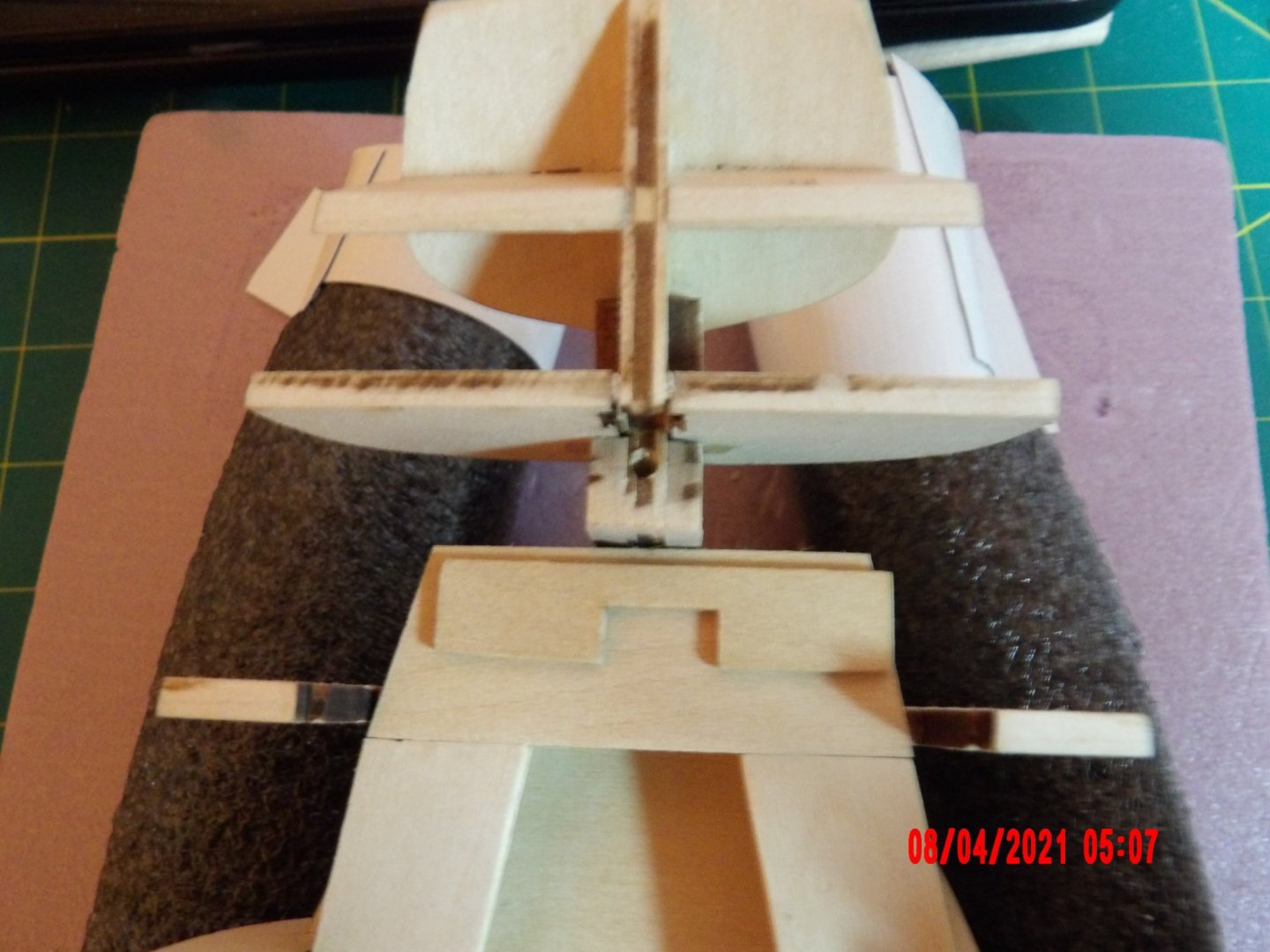
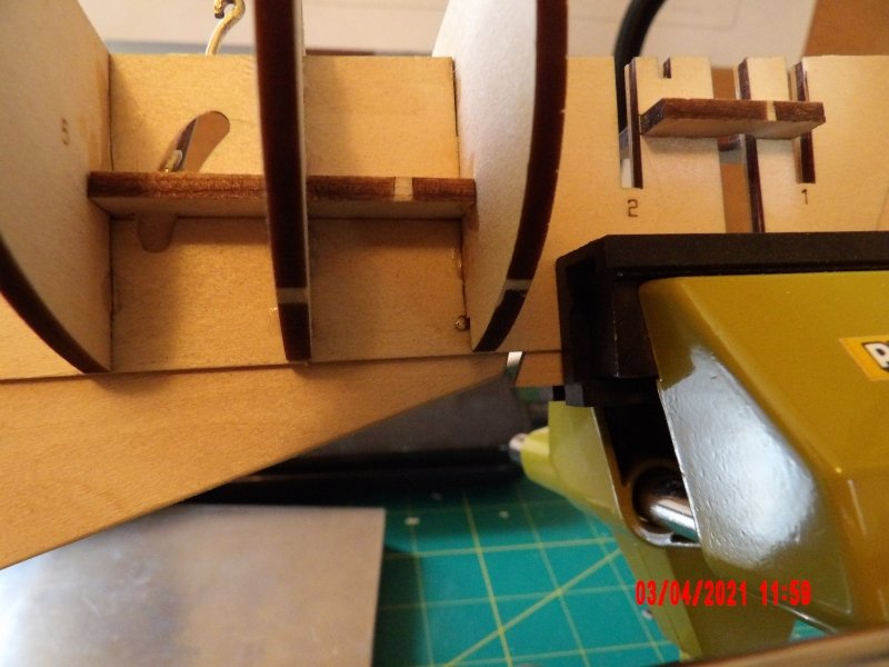
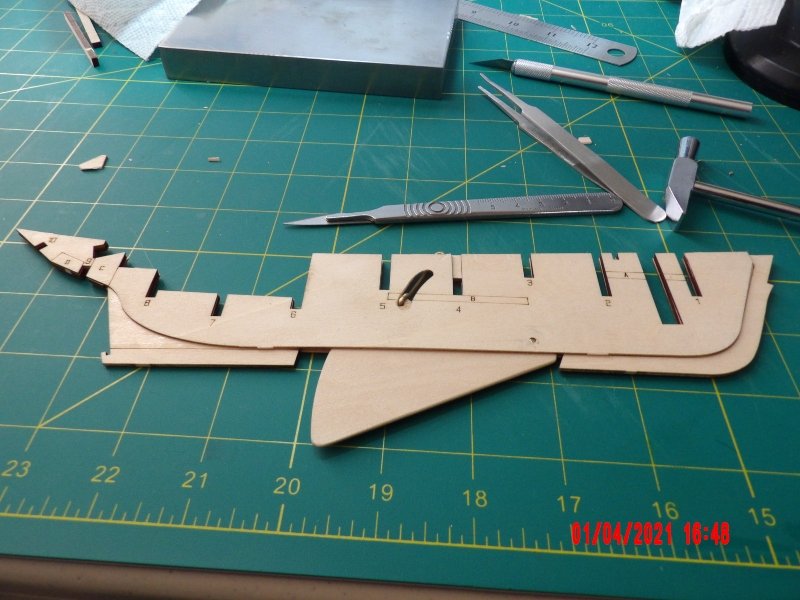
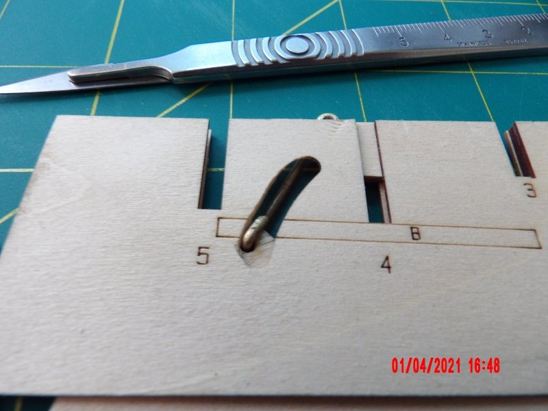
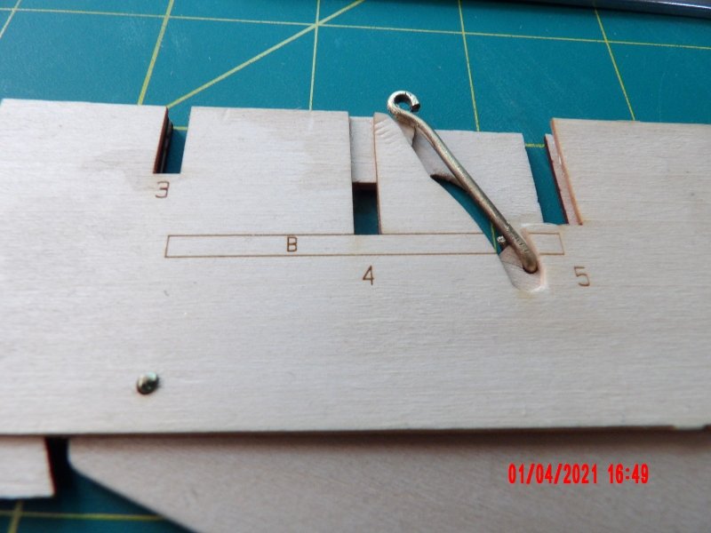
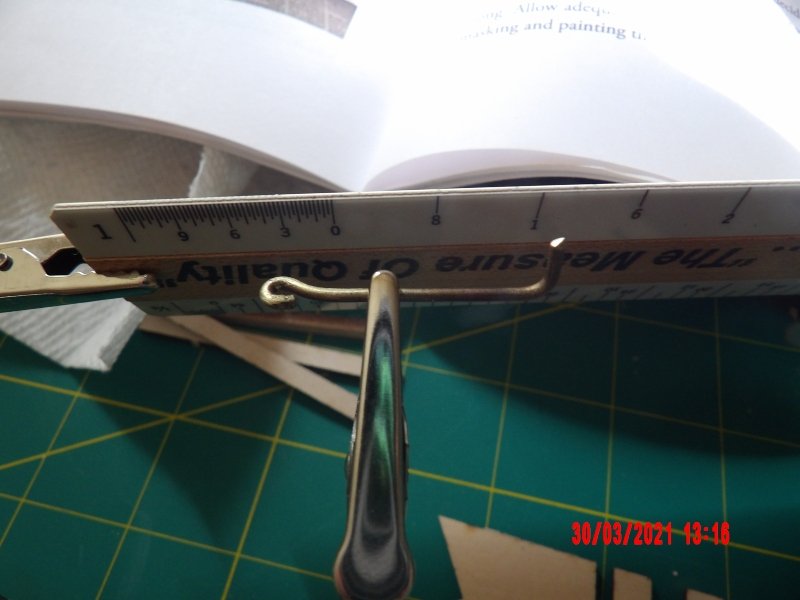
Well. this kit is humbling me. . . I decided that the centerboard pivot point rod needed to be made into a rivet, although the instructions did not state so explicitly. I did that operation with a greater level of success than I did on the sailing pram, after dimming the lights and heating the brass rod to cherry-red as instructed. I had thought that the curved travel slot did not need enlargement, but after gluing the port side spine piece in place, saw that I did not have full travel of the centerboard. I enlarged the slots on both port and starboard sides of the spine with the new love of my life- the surgical scalpel. What a game-changer! I am sure to hurt myself with it soon, but it is so worth it. The section of the port side spine adjacent to the operating rod needed some more glue where it met the central piece, as it had curled, and I broke it off attempting to add some CA glue. This area is extremely weak. Before: After break: I think I will be able to attach a custom piece to the reinforcing piece "B" and all will be good for the install of frame 5. A void is left between the outer spine pieces at this point to allow for moving the operator to a forward locked position with the centerboard retracted (I think). The pictures in the manual seem to confirm this idea, however, the diameter of the operating rod did not allow for this movement in the void area. Maybe if I'd achieved a tighter bend. . . Now, with the outer spine broken, the rod can easily be moved to the forward position. . . Lastly I had some curvature/warping of the spine, probably a result of my attempting to clean up white glue mess with water. which was unnecessary because this will all be hidden. I don't recommend this, but I took a regular clothes iron, wetted the surface and straightened it out, and weighted the assembly to sit overnight. It seems to have worked, and I will buy a small travel-sized iron for this kind of thing for use in the future. AM update: the spine lays dead flat now! Two steps forward, one back haha. And look a my beautiful rivet! Update 4-3-21: I see now that the rivet was not intended by the designer. . . see below.
- 52 replies
-
- 3
-
-
- Model Shipways
- muscongus bay lobster smack
- (and 1 more)
-
Made the brass operator rod. Got a pretty tight eye. Having the right tools is helpful for this kind of thing. The round-end jeweler's pliers recommended by the kit author really worked well.
- 52 replies
-
- 3
-
-
- Model Shipways
- muscongus bay lobster smack
- (and 1 more)
-
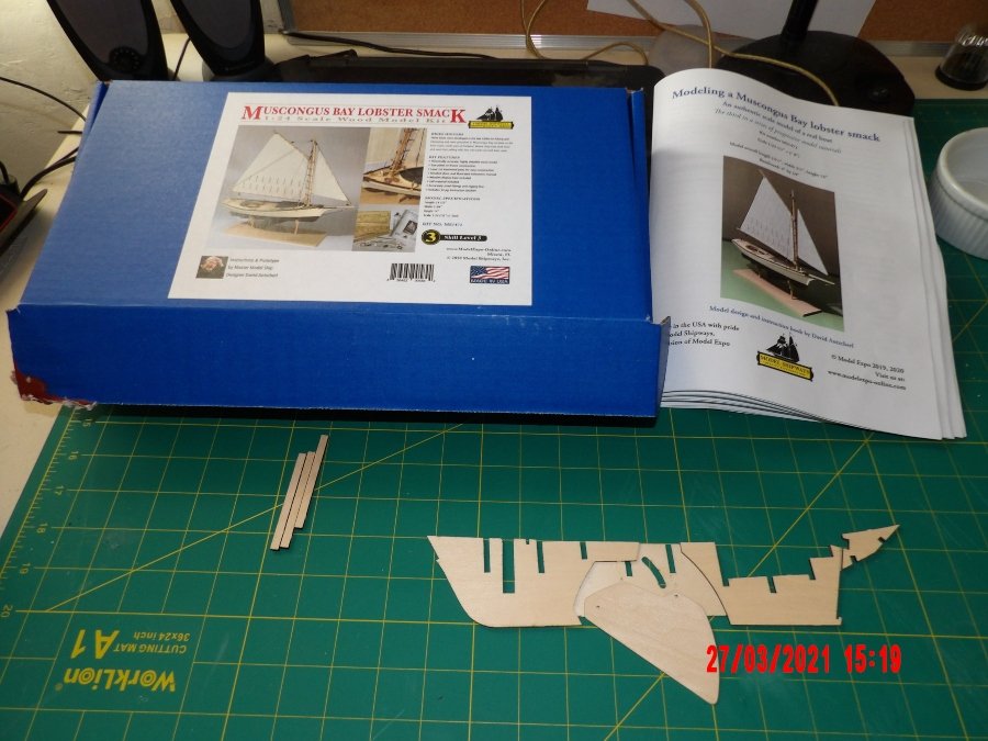
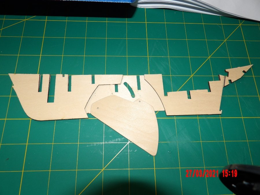
I received the kit and paint set yesterday! I had downloaded and read the manual upon ordering and so began to assemble the central spine this morning with the feeling that I understood these steps. I glued the center pieces to the starboard spine using the supplied spacers. Even so, I ended up with misalignment at the top of the spine and on both walls of the bulkhead frame slots. Should have done this under magnification. I did a little surgery and sanding at the top of the spine, and will defer refining the slots until placing the bulkhead frames. Since the profile of the spine is preserved with char present, I don't think there will be a problem resulting directly from this misalignment. Will be more careful with the other side of the spine. I then freed the centerboard and cleaned and rounded edges. The next step is to form the brass operator rod for an adjustable centerboard, if this is a desired feature.
- 52 replies
-
- 4
-
-
- Model Shipways
- muscongus bay lobster smack
- (and 1 more)
-
Thanks much, Gregg and G.L.! Bob
-
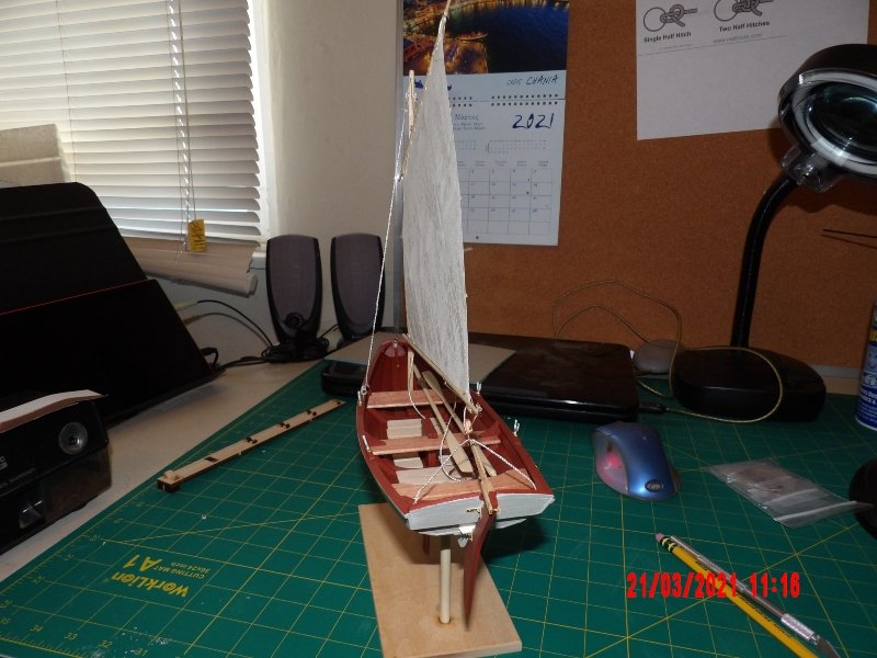
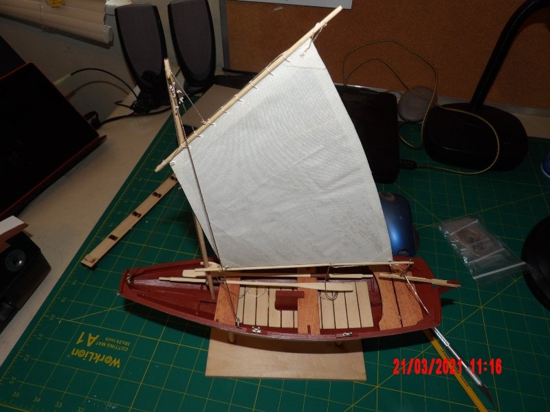
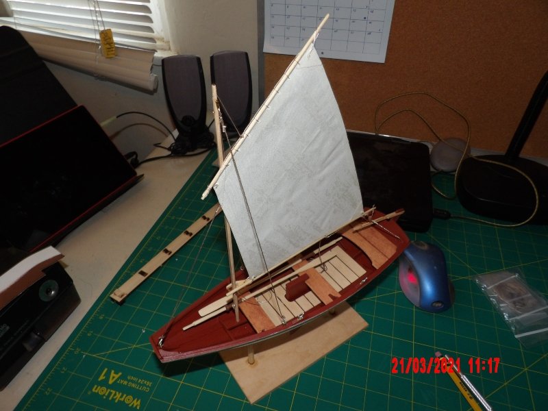
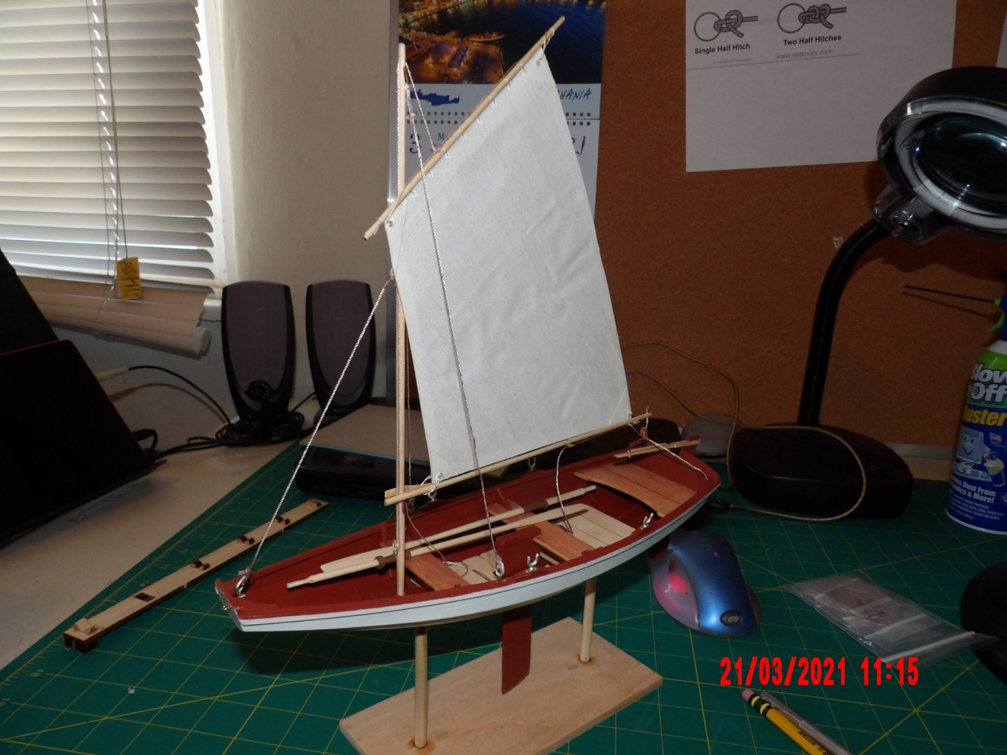
Finished! Thanks to all who helped me, commented and "liked."
- 45 replies
-
- 6
-
-
- norwegian sailing pram
- Model Shipways
- (and 1 more)
-
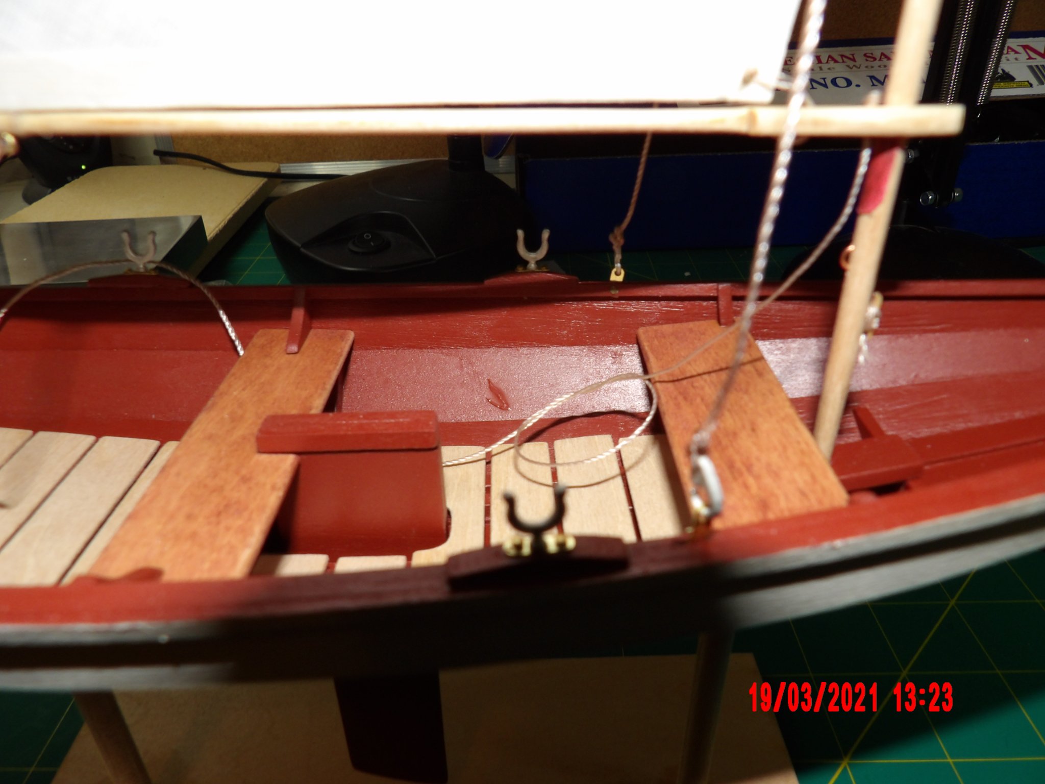
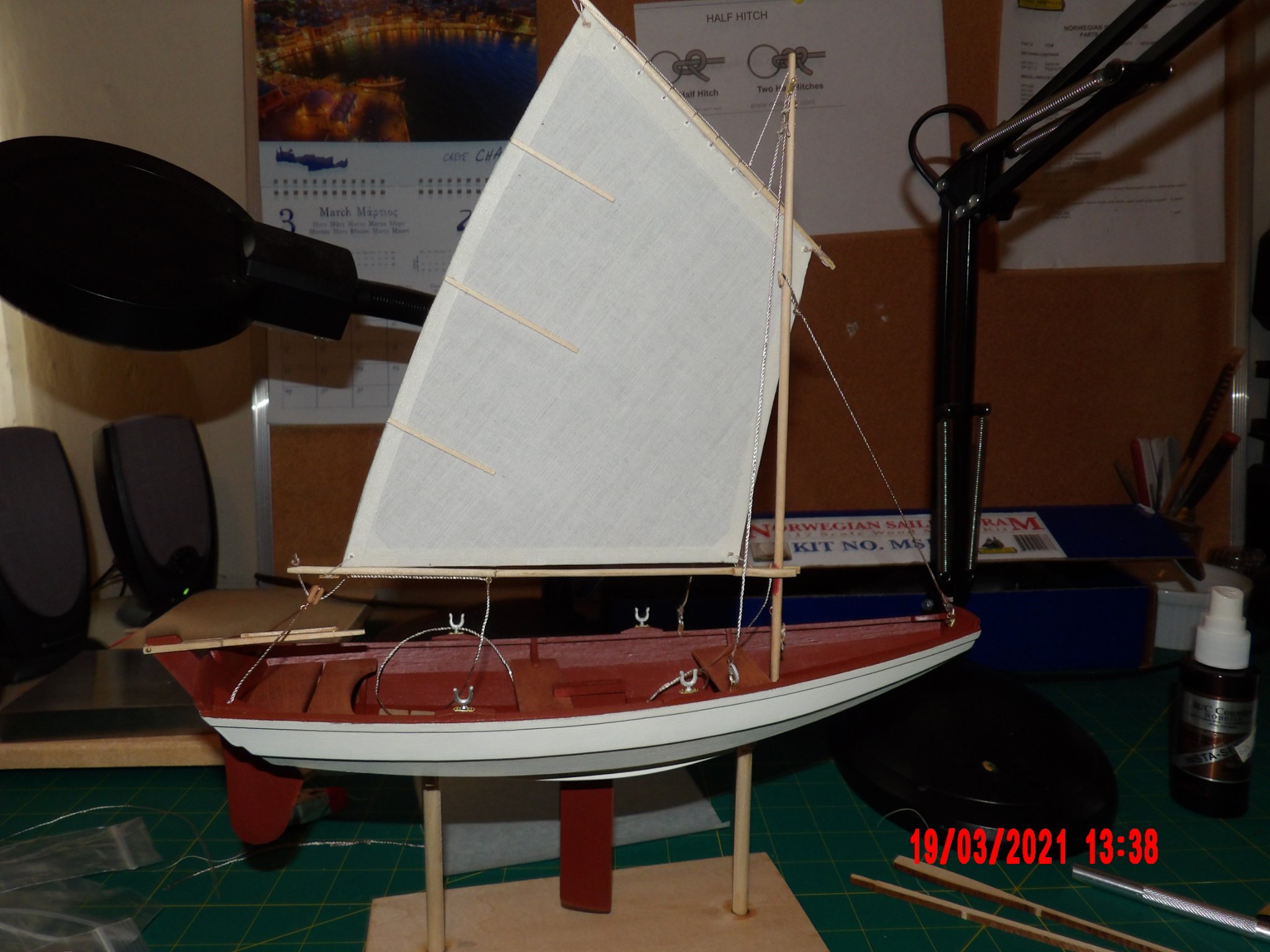
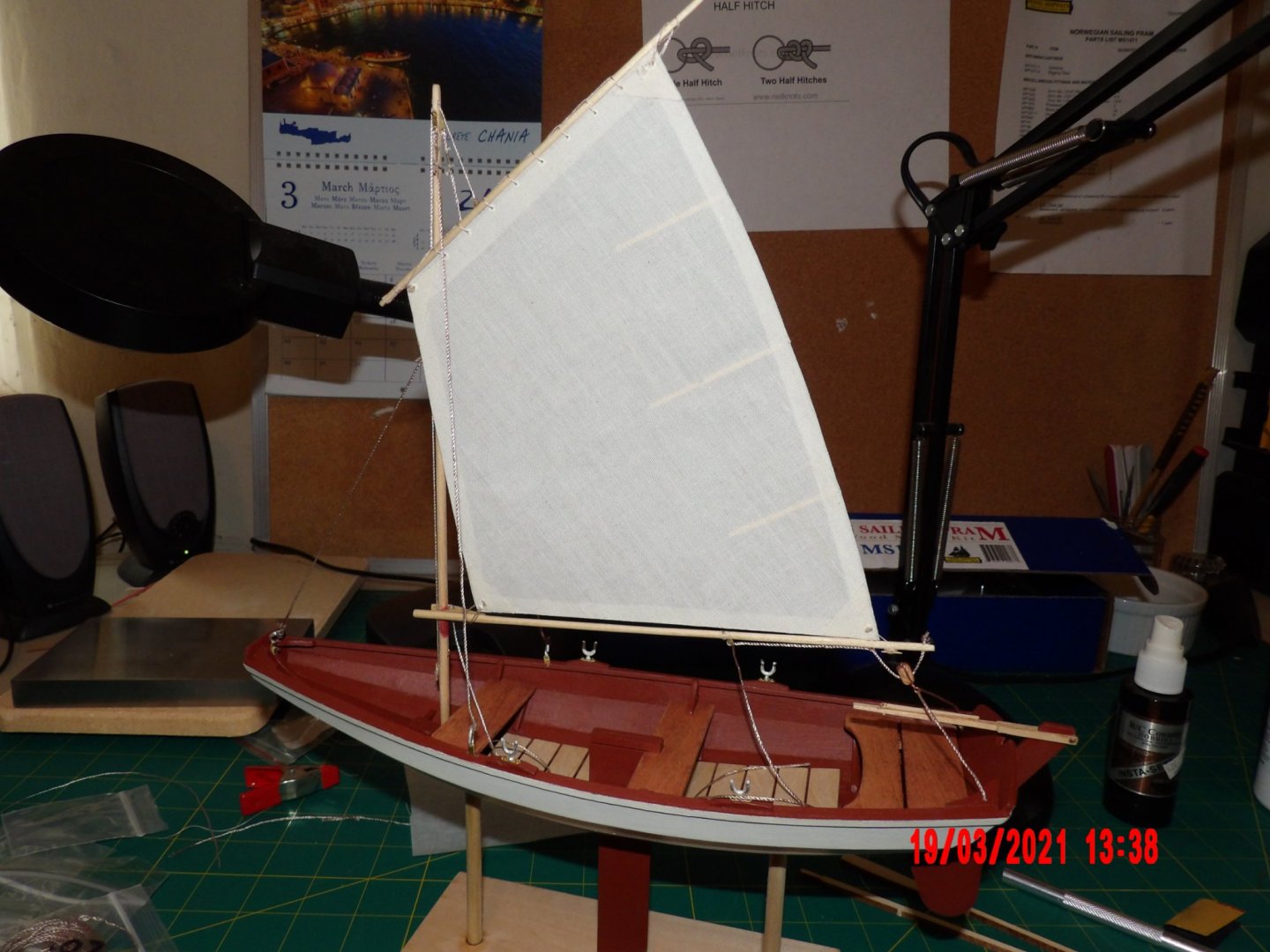
Rigging is done. Brutal, but fun. I was trying to get the sheet line through the middle eye on the boom (where I had broken it) and it broke again. I did an in-place repair, as I could not see starting over. I was able to CA glue it back together reasonably straight, but it is more visible than before. During this operation I spilt a good blob of CA onto the hull interior, and did not notice until it had dried, and anyway my hands were occupied. I don't know if I will attempt to correct. Sometimes it's best to walk away for a while. I think artful placement of the oars may obscure this (to all but myself), or maybe I can make something, a bucket or picnic basket or whatever, to set in front it. I also lost the brass eye to the break, but had some small eyebolts and put one in the remaining hole. A little out of scale, maybe. . . The manual calls for passing the traveller line through holes in the stern transom knee. This is a typo, should have been stern quarter knee, but there were no holes. No big deal to drill them. There is a hole in the transom knee, but it is unused. The boom hit the rub on the mast, but a little high- that's the end result of my not adding a stop to the mast step. I tried to improvise, but saw potential for damage, so the mast is resting on the floor. I wired up the block for the traveller upside down, the hole for the rope should have been at the top. I can also see that the under sizing of the sail (see earlier post) left more mast exposed above the sail, but it's probably no more than 1/4 inch extra. I just have to finish the oars, and coil the ropes and glue them to the floor. I'll make one more post at completion and call it good. I can recommend this kit to other beginners, after they have completed the dory. I bought all the necessary tools and some of the optional ones, and used them all. The jeweler's broaches are a must-have, and they are beautiful little things in themselves. The techniques taught in the manual will serve well into the future. I learned so much, including terminology and some history. Based on my experience with this model, I ordered the Muscongus Bay Lobster Smack yesterday.


- 45 replies
-
- 3
-
-
- norwegian sailing pram
- Model Shipways
- (and 1 more)
-
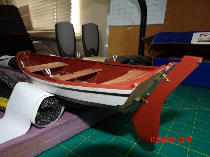
Finished the metalwork! The Micro-Mark pin insertion pliers was well worth the money.
- 45 replies
-
- 1
-
-
- norwegian sailing pram
- Model Shipways
- (and 1 more)
-
Butterball, to the best of my understanding the bevel lines should marry to the next plank. Consider the curvature of the frames. Without a bevel on one side, you'd not be able to meet the lines. They kind of overlap, but it's not a full overlap. I know this is confusing. If I had the means I'd draw a picture. There are pictures and explanations somewhere on this site, I've seen them, can't find my way back at the moment. Draw yourself a picture, I wish I had, exaggerate the curve of the hull, draw the planks in cross-section as flat, and you will see how it goes. I hope a seasoned vet will jump in and help you. I I find something in the meantime, I'll be back. Bob b