bobandlucy
-
Posts
512 -
Joined
-
Last visited
Content Type
Profiles
Forums
Gallery
Events
Everything posted by bobandlucy
-
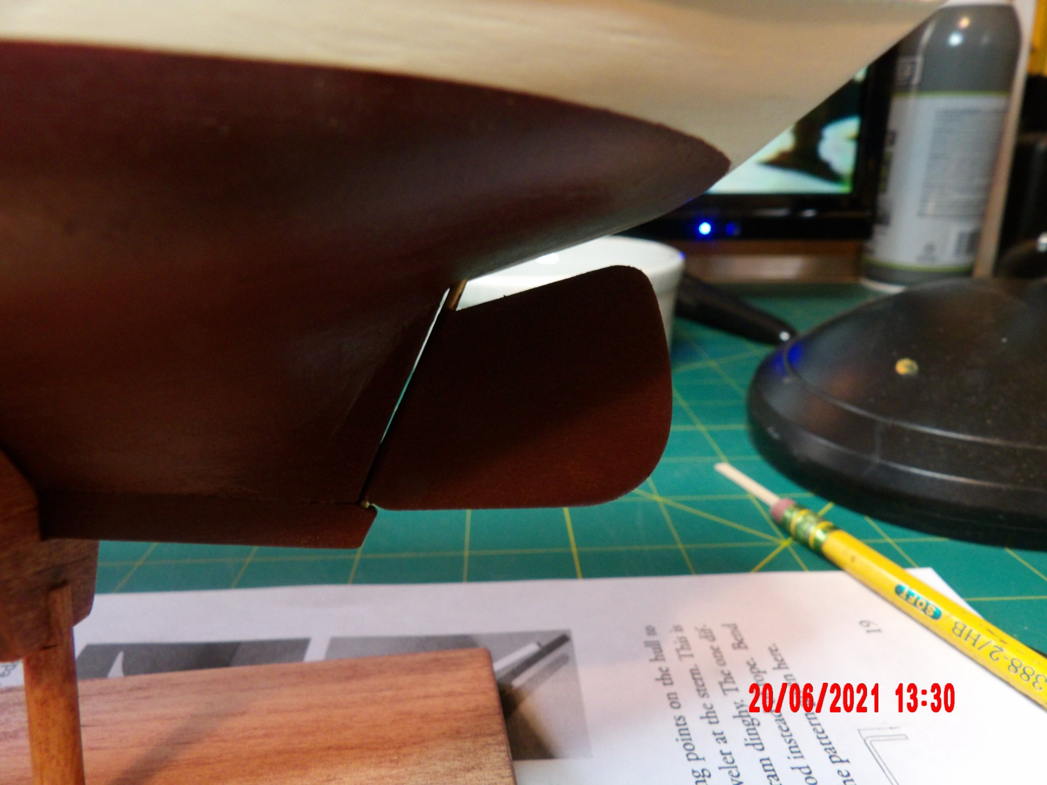
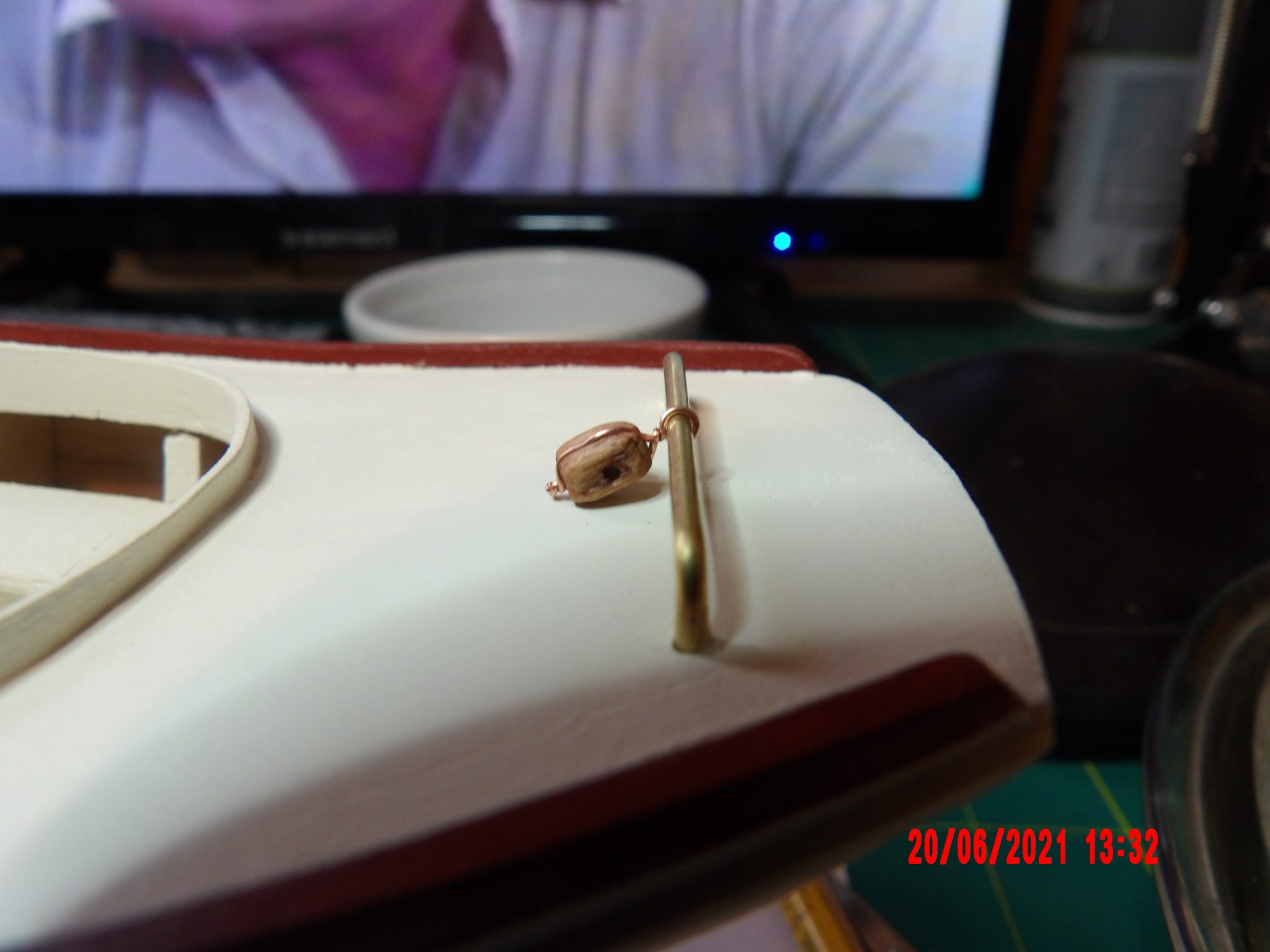
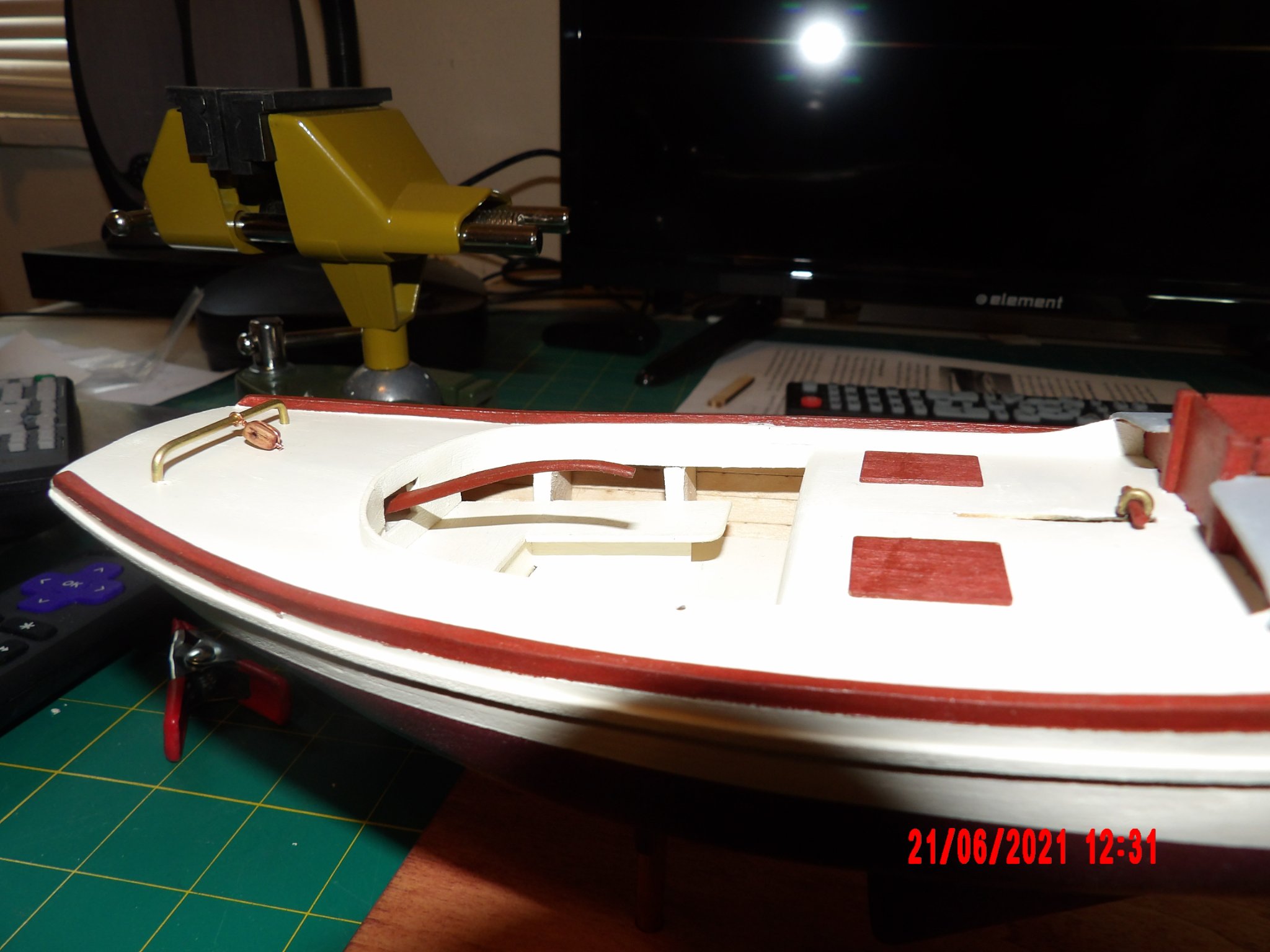
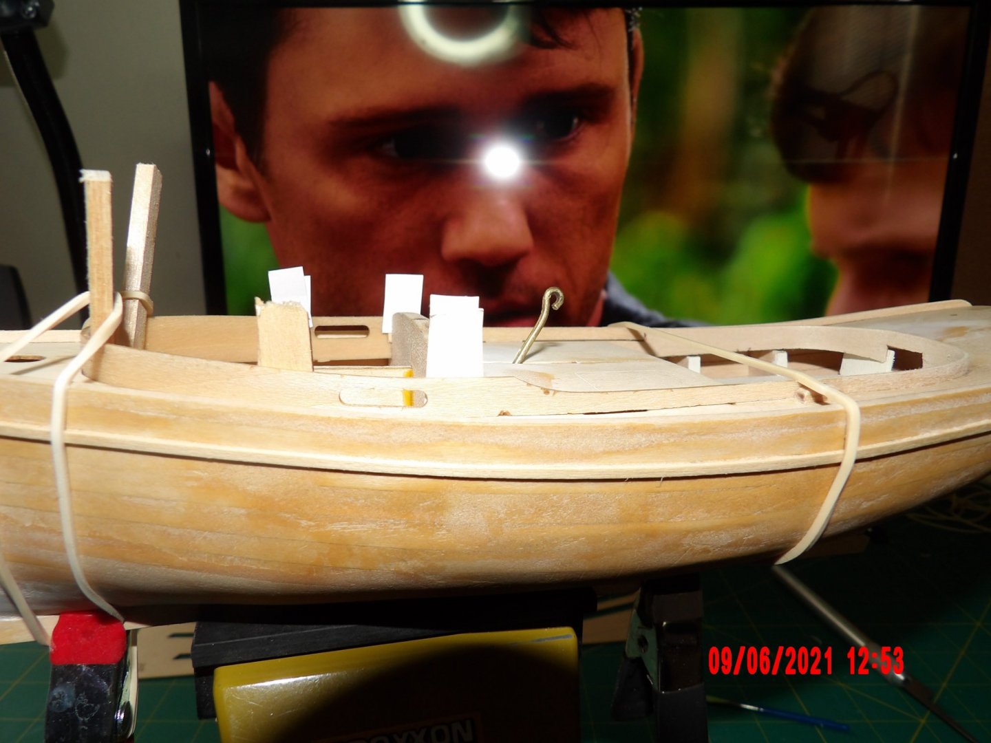
 I neglected to mention in the last post- that the cabin roof was glued in off-center so the overhang was not visually pleasing. I cut/sanded the overhang off flush with the wall below, and glued on a "bumper" rail all around using the same material as for the rub rail. I think it looks OK. I installed the rudder. tiller, traveler and block, the centerboard operator rod handpiece, and the trail boards. The tiller was challenging- my first attempt with epoxy failed to set, so I reached into the void with gel CA glue on a toothpick and that worked. The block is hardwood, and was hard to shape. I'd recommend sanding rather than cutting as I broke it, but was able to glue back together.
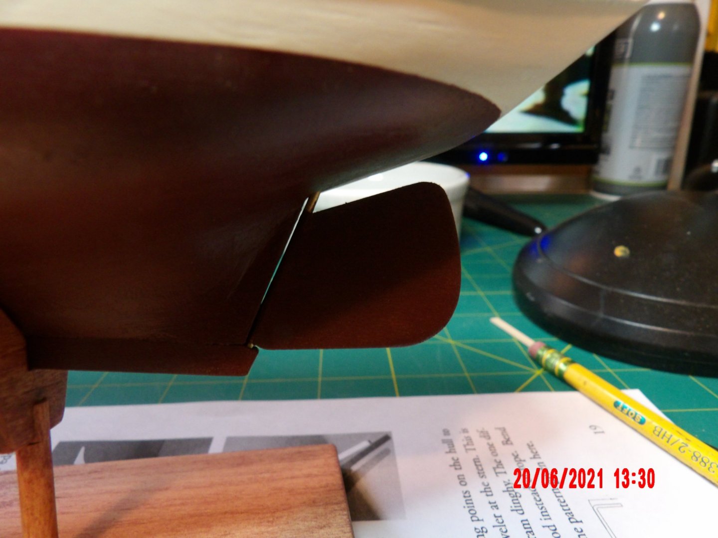


- 52 replies
-
- 3
-

-
- Model Shipways
- muscongus bay lobster smack
- (and 1 more)
-
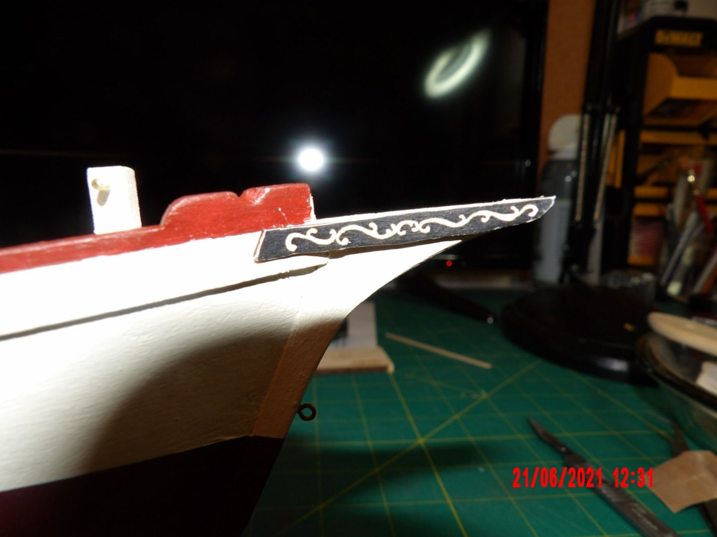
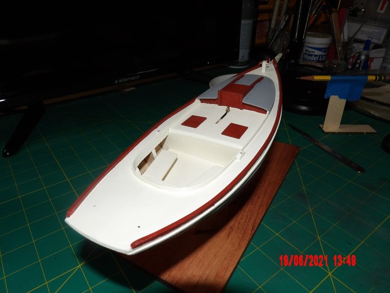
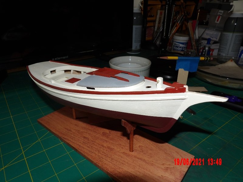
Painted the toe rails and mounted on the stand. There are a couple of areas where the paint lines are not as crisp as I'd like. I touched them up as best I could and decided that additional work might cause a worse outcome. One area I may try to touch up more is the intersection of the cabin bulkhead and deck. This area and the toe rails near the cabin walls were hard to mask. Yes, there is a lot of white! I may paint the oar lock pads mahogany to add additional contrast, but I think with the addition of the tiller and the mast/rigging all will be OK.
- 52 replies
-
- 5
-
-
- Model Shipways
- muscongus bay lobster smack
- (and 1 more)
-
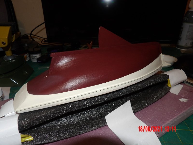
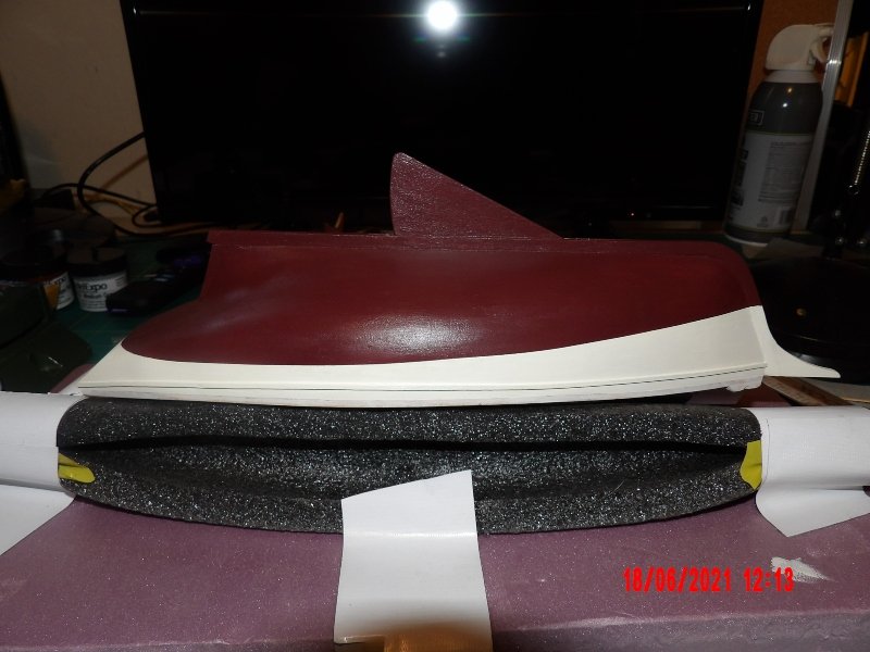
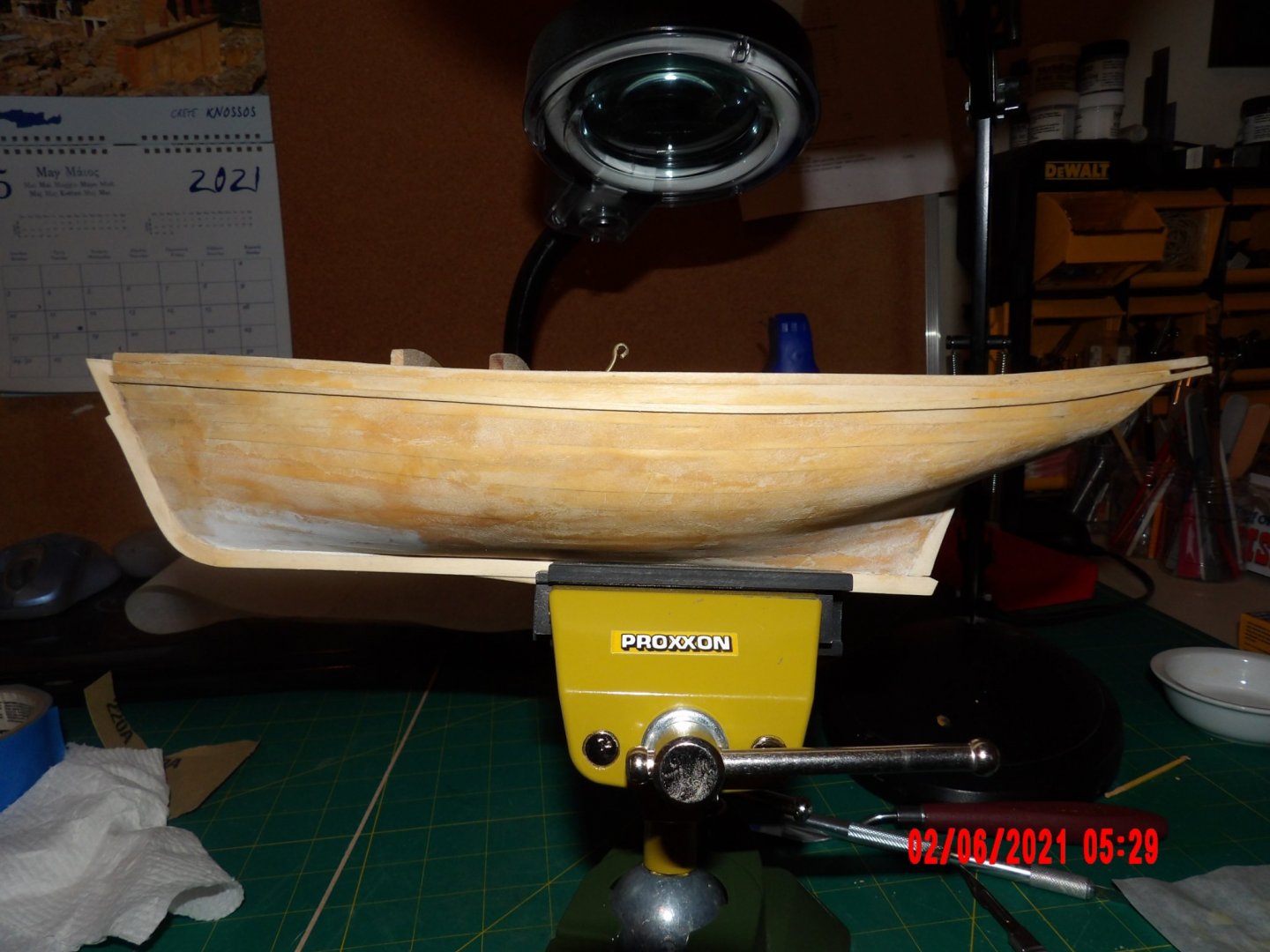
Painting. Came out pretty good, I think. Was a bit puzzled when drawing the waterline, as position on the stand changed the line position. I decided that the line should marry with the bottom line of the transom.
- 52 replies
-
- 3
-
-
- Model Shipways
- muscongus bay lobster smack
- (and 1 more)
-
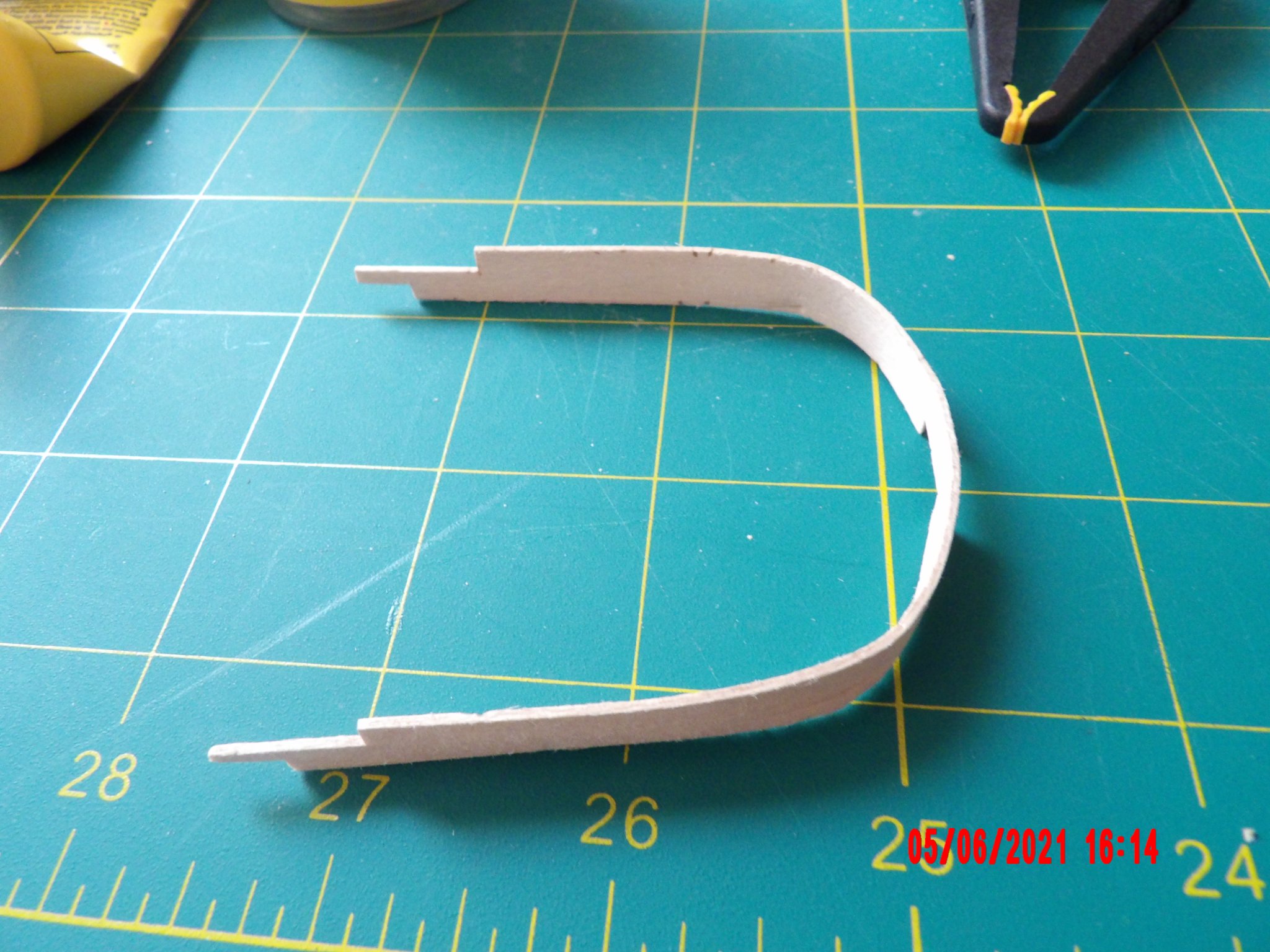
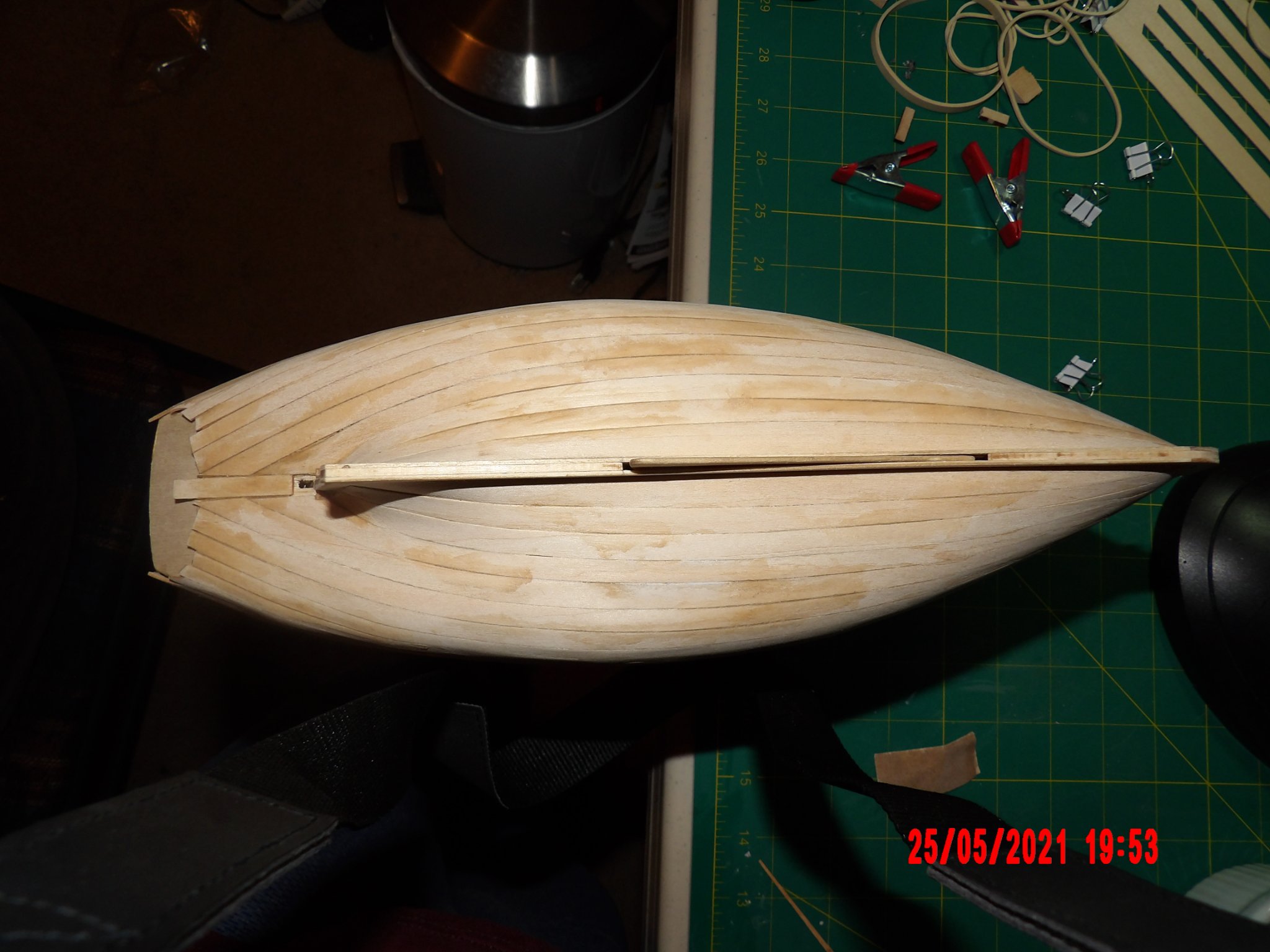
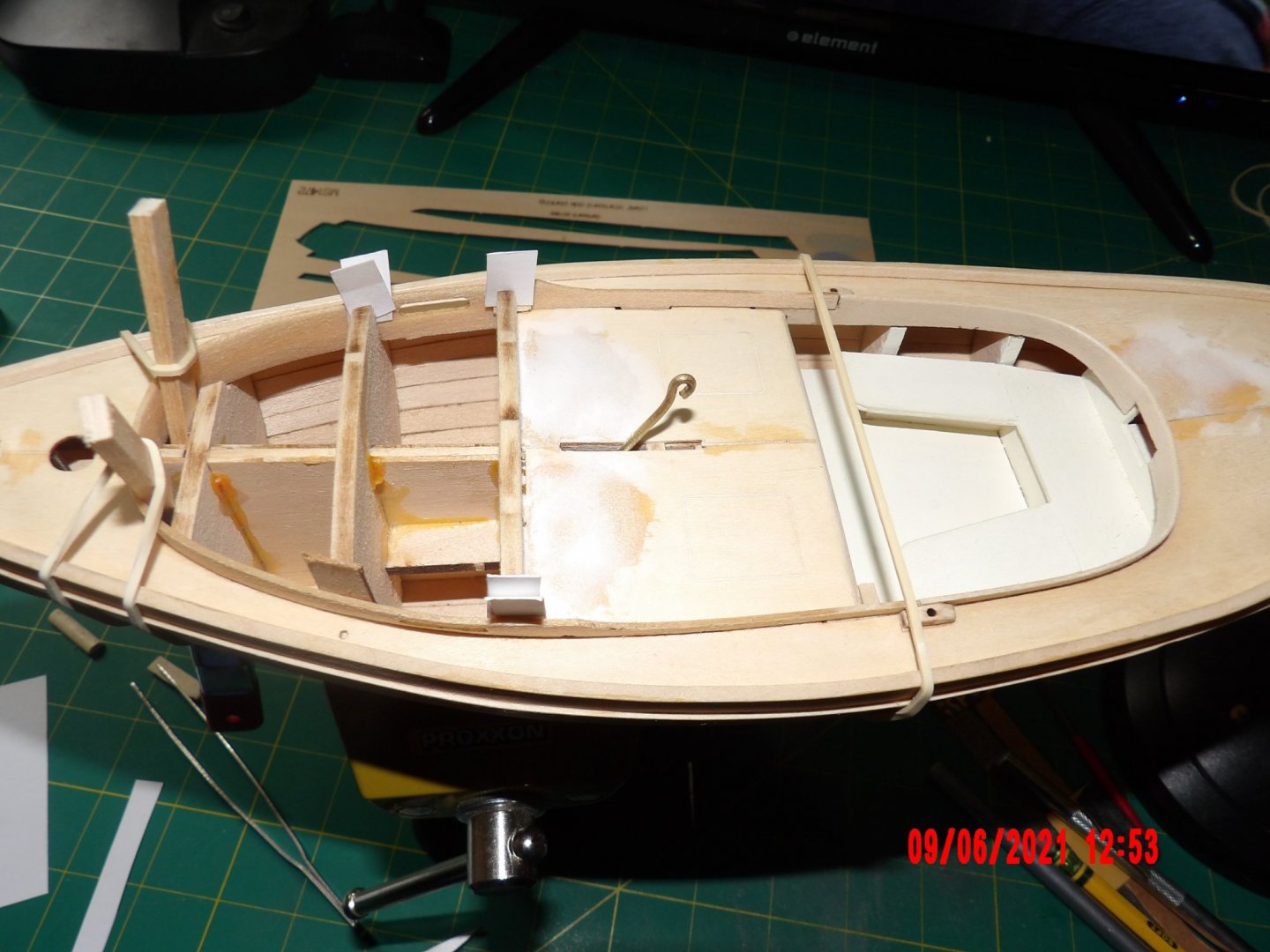
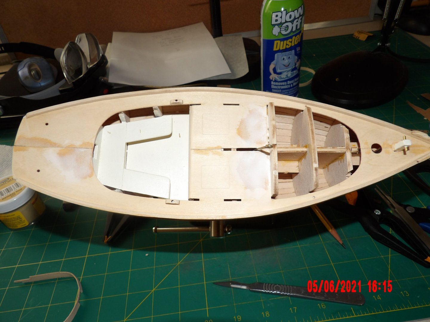
Glued in the coaming and cabin sides. I did not pre-paint them as I will be priming and painting the deck due to all the fill used. I'm thinking some light buff or cream paint that might resemble wood, if I can find it. Any ideas? First pic shows a difference between the prototype and this model. The operating rod for the centerboard is shown in the kit manual as resting in the down position all the way to the end of the slot towards the stern, so that it rests between the two wet well covers. In my opinion, this would be the most attractive position for display. As you can see, in my model the rod movement is stopped by the bulkhead below the deck. I guess this is my error, I should have notched the bulkhead earlier on. It will be tricky to correct now, but I may give it a shot. . .
- 52 replies
-
- 4
-
-
- Model Shipways
- muscongus bay lobster smack
- (and 1 more)
-
Good job so far! Regarding tools- the list provided with the kit is pretty complete. I've found the broach set (Amazon, from Germany) is very useful. You can drill holes undersized and then open them up very precisely to fit a part. I've also found a rotating vise to be indispensable. Bob
- 160 replies
-
- 4
-
-
- Model Shipways
- norwegian sailing pram
- (and 1 more)
-
I was feeling pretty good, sanding, filling, sanding filling. . . when I realized that what I thought was a white deck in the instruction manual was actually unfinished wood. Had some warping of the deck which required filling, and I did a pretty good job in restoring the slight curve to the surface. Now I think I have no choice but to go with painting. I had seen that some others stained the deck, but I wanted to keep to the scheme presented. I realized I had gone wrong when I read the instructions to pre-paint the coaming (not for the first time) to avoid awkward masking. Thought "why pre-paint as it's all white?" Duh! I tried to shape the coaming. It looks really rough. I may try again if I can find a piece of scrap. Some days I should just stay out of the room. . .

- 52 replies
-
- 5
-
-
- Model Shipways
- muscongus bay lobster smack
- (and 1 more)
-
Looks great Auger! I have this kit but am waiting for confidence to build through other models. The staircases kind of intimidate me. . . Where did you find the human and animal figures? Bob
-
Very good job! Deserving of a nice display case. . .
-
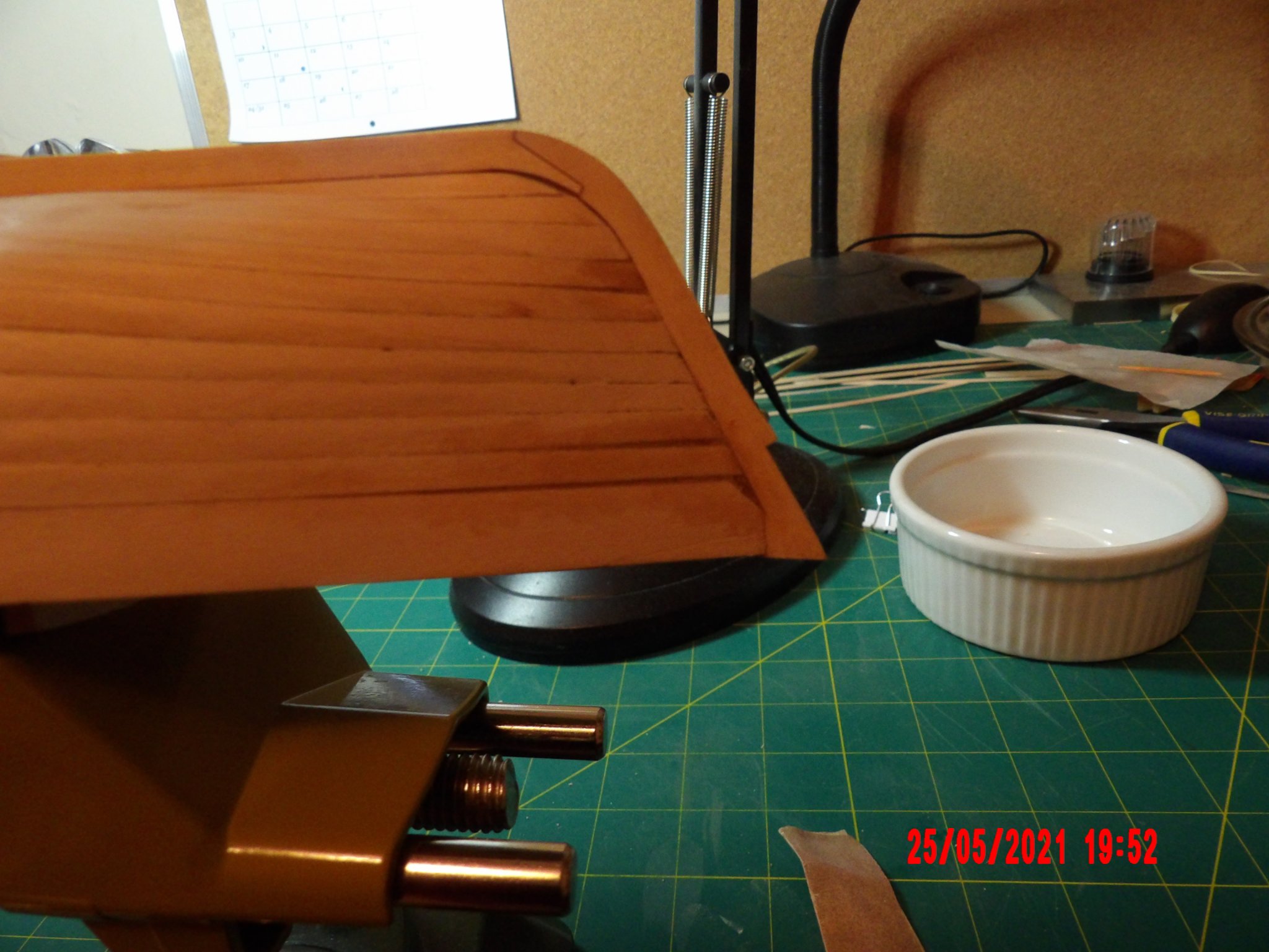
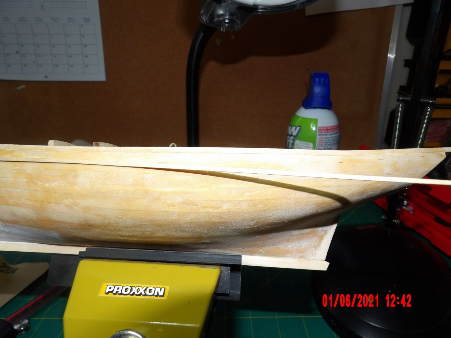
Added the toe rails and one rub rail. Instructions call for the rub rails to be 1/4" below the top of the toe rail, until aft of the deck house (cabin?), where it should rise gradually ending 1/16" below the top of the transom. I glued the piece on to the point where the rise would begin, then holding it to a mark at the transom, made marks every inch or so, then continued gluing incrementally. There is a slight rise to the hull near the center of the boat, or a slight dip in the rub rail, or both- which is now apparent, but overall I am happy with results.
- 52 replies
-
- 5
-
-
- Model Shipways
- muscongus bay lobster smack
- (and 1 more)
-
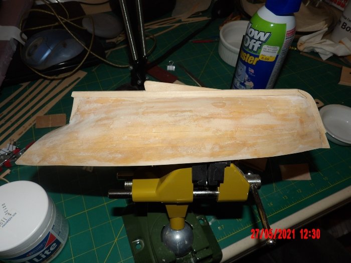
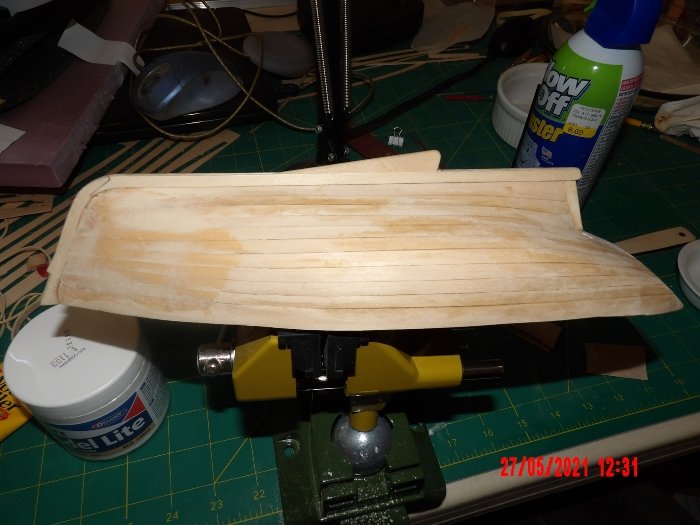
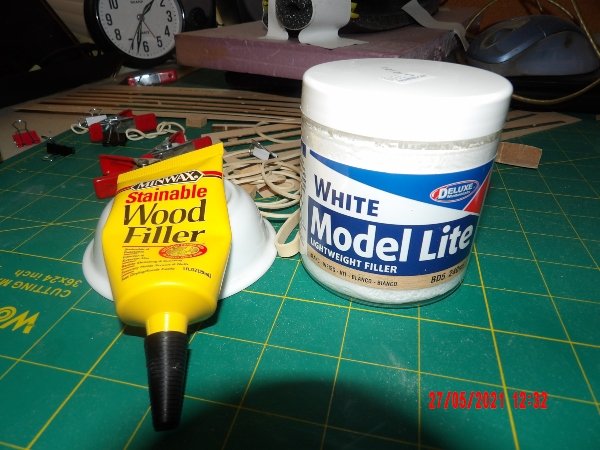
Druxey, Will & Skibee- Thanks for the encouragement. I began filling and sanding. Most of the defects are edge to edge, I was lucky to not have any apparent depressions between the frames. On the theory that I am not seeing everything, I applied filler all over, then sanded down. I experimented with two different fillers. The Minwax discolors the wood and is very grainy, but sands down OK. The Model Lite stuff is strange indeed, really fluffy stuff that sands to a very smooth finish, but it is too easy to over-sand thus removing the fill. I added a little water to both types to make them more workable. Pics are of one side "finished," and the other side just begun towards the bow. The finished side is smoother than it appears. . .
- 52 replies
-
- 4
-
-
- Model Shipways
- muscongus bay lobster smack
- (and 1 more)
-
Skibee, this looks fantastic! Yu must be feeling pretty good now! Bob
-
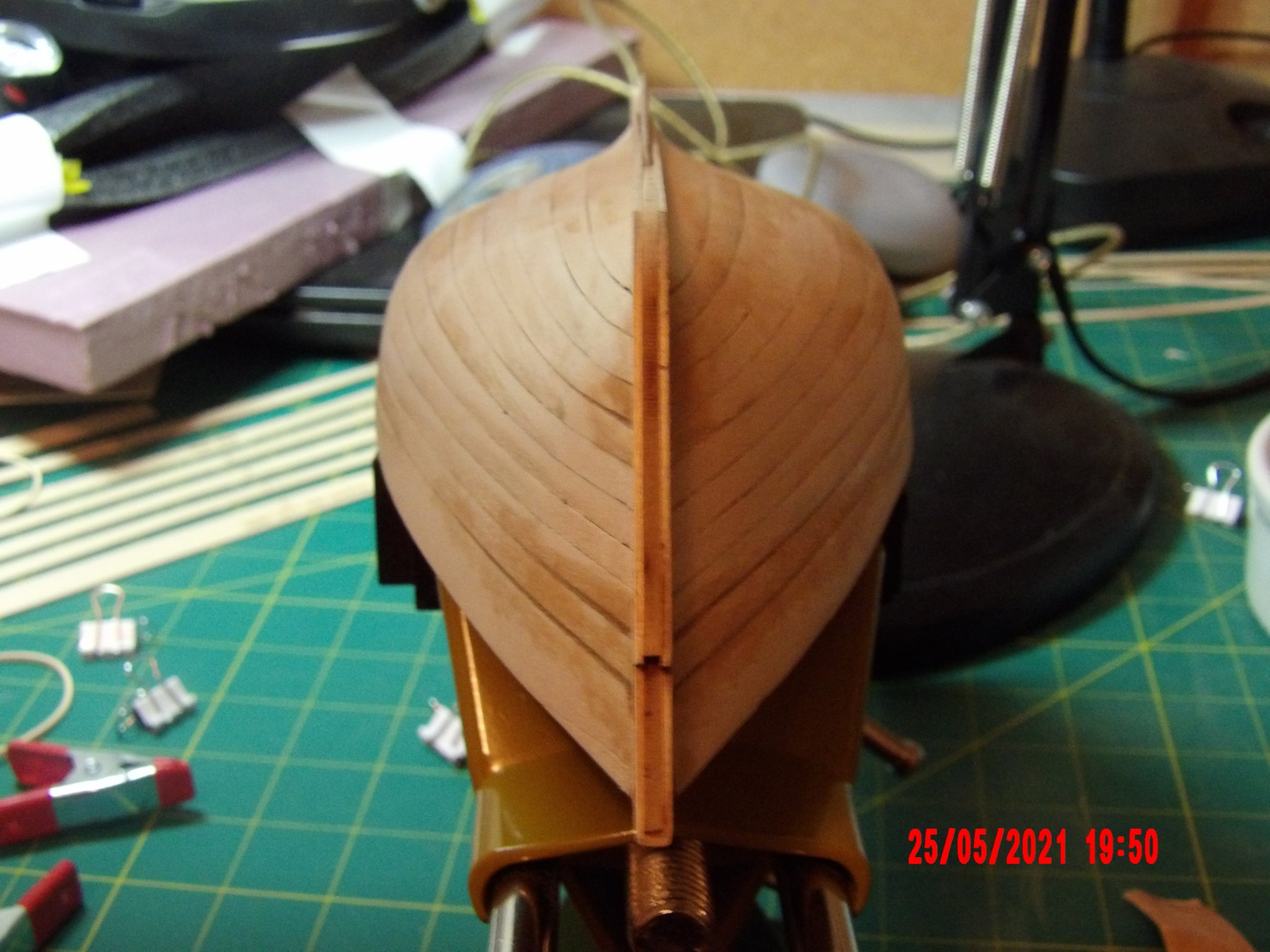
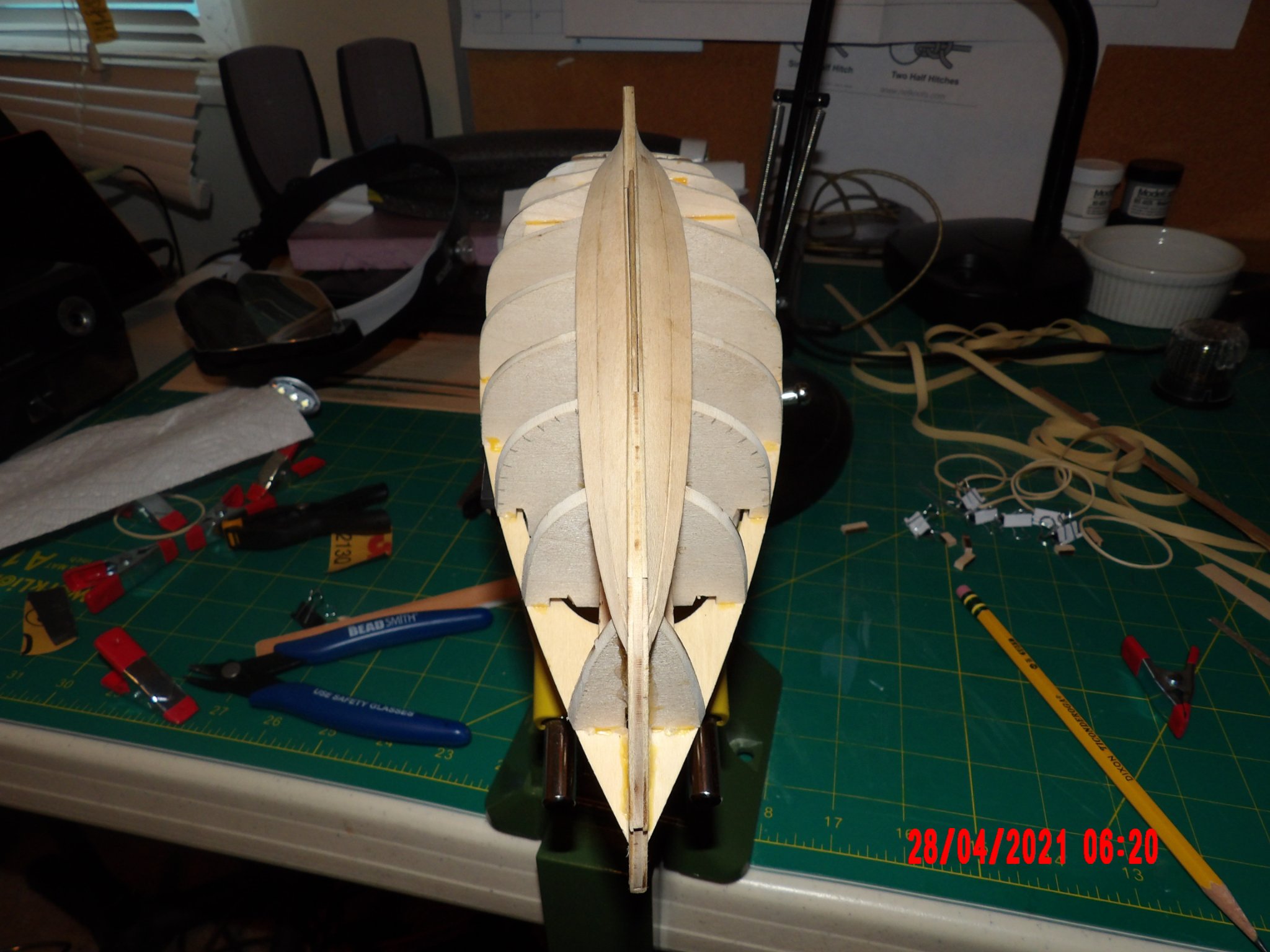
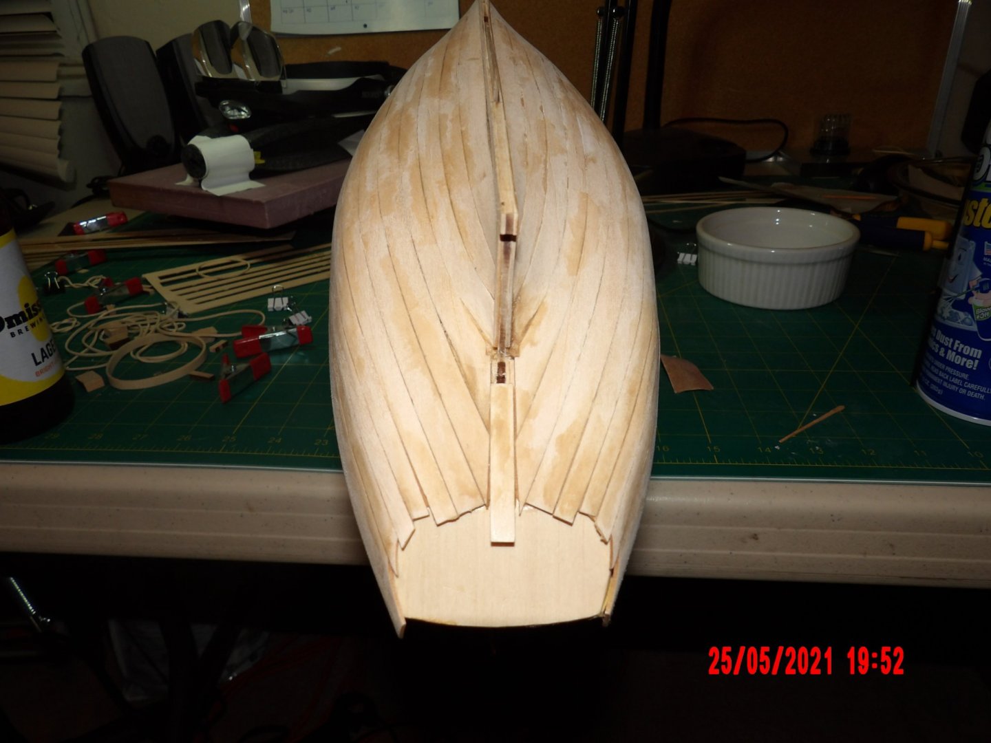
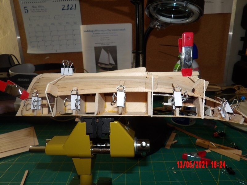
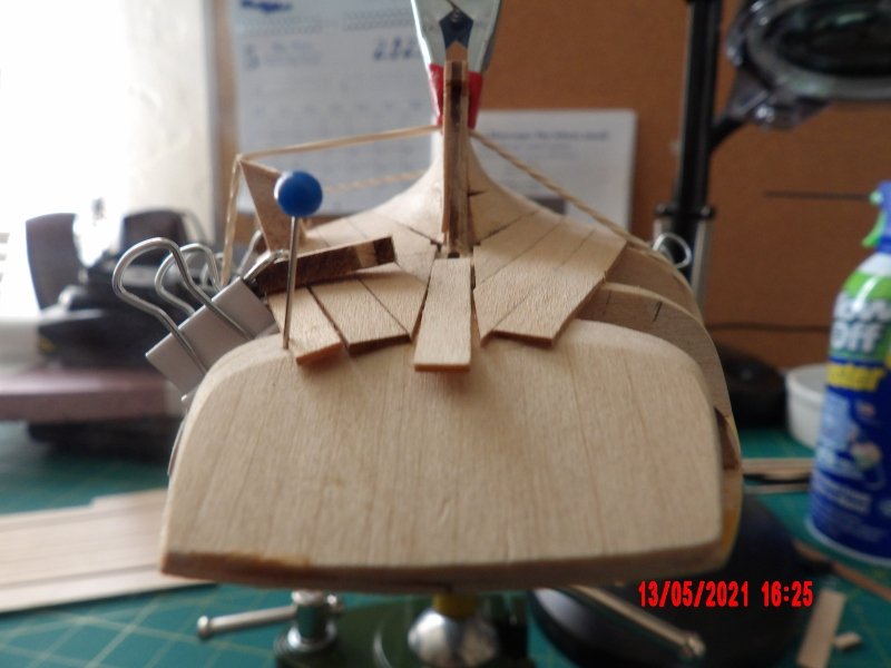
As I began to place the #9 and sheer planks I saw that I was below the level of the deck towards the bow. The error was so small that I did not want to fashion a stealer or make new planks. I decided to leave gaps between these two planks, then filled with glue/sawdust mixture. This fill shrinks somewhat, and I will address this with additional filler. I also used this fill method on some other gaps throughout. My fairing was as good as I could make it, all the planks laid well against the frames, my problem was edge to edge, and results were improved as I did a better job with beveling and bending. I won't try and hide in the photo the ridiculous cut I made on the sheer plank at the spine rabbet at the bow. . .


- 52 replies
-
- 5
-
-

-
- Model Shipways
- muscongus bay lobster smack
- (and 1 more)
-
Love the instrument board! Bob
-
This is just incredible work. I love the details, the cabin and the machinery. The simulated water is amazing. I don't think I'm ready to tackle this model yet, but I may buy it now as I'd like to know it is there waiting for me.
-
Thanks ERS Rich. That's some shop you have there; you are obviously a skilled woodworker. The albums of your finished models are impressive, and you've also made some beautiful display cases! I am edge-gluing the planks with PVA. I am taking a lot of care when wet-bending, and I let the piece air-dry in place for a few hours, so there is no need to force it into place when gluing. That is why light finger pressure is enough- I just hold it in place for a couple of minutes until the glue grabs. I like gluing incrementally because I can pay more attention to edge alignment in a shorter span. It's working for me, and I am in no particular rush. Using CA raises my blood pressure, maybe I'll get enough confidence some day. . . Bob
- 52 replies
-
- 2
-
-
- Model Shipways
- muscongus bay lobster smack
- (and 1 more)
-
Congratulations! You should be proud of your effort! I like the way you laid the oars across the boat. You're really going to like the Pram. I have mine in the living room and can't stop looking at it. . . Bob
- 85 replies
-
- 4
-
-

-
- Lowell Grand Banks Dory
- First Build
- (and 2 more)
-
Continuing with the planking. After my last post, as I readied the #2 plank, I saw that I was way off the mark. I discarded the two kit-supplied planks and made two new ones, using the carrier sheet as a template, and then cutting to the outside of the lines, resulting in wider planks. This corrected the problem, at least for the next two planks. Now, as I prepare the first # 6 plank, I see that it is slightly off the mark towards the stern. It lies very nicely though, and I will install it hoping that my previous correction puts it all within the margin of error provided by the oversized sheer plank at the top. I do have some gaps to fill, but am pleased by the lines viewed from both the sides and from the ends of the boat. Look at the edge line created as I wet-bent and clamped the first # 6 plank in the picture below, to me it looks beautiful. Lastly, I wanted to mention that for the last several planks, I am incrementally gluing the planks across 3 frames at a time, and using fingers to hold the plank in place until the glue grabs. This takes longer, of course, but I am getting better results from this method, as opposed to frantically trying to apply glue and clamps down the length of the boat after gluing one end down.
- 52 replies
-
- 3
-
-
- Model Shipways
- muscongus bay lobster smack
- (and 1 more)
-
I had to drill larger holes for the becket for my model. . .
- 85 replies
-
- 2
-
-
- Lowell Grand Banks Dory
- First Build
- (and 2 more)
-
Thank You! I checked my rigging line and found the same diameter discrepancy. I will be contacting Model Expo as well. Bob
-
You are just flying along like you've done this for years! Looks beautiful! Bob
-
Finally began planking, added the garboard and first strake, and am slightly off the mark towards the bow. This planking style is definitely a step up in difficulty! I will see how number two goes and adjust if necessary. I'm not too concerned yet. The garboard came a little short at the bow, and I trimmed the first strake a little short- so I placed it with the gap also at the bow so that most filler will be added there. From the pictures in the manual, it seems that the finished hull should be smooth and not show the lines of the planks. . . I think that will be impossible for me to achieve without using some filler, but I think that is to be expected. In general, the fairing seems to allow a good lay of the planks so far- I don't see any serious distortion and there is good contact across all frames.


- 52 replies
-
- 4
-
-
- Model Shipways
- muscongus bay lobster smack
- (and 1 more)
-
Wow! Looks very clean with a perfect shape. Sure this is your first? Bob
-
Congratulations!
-
Looking good, Skibee! I am starting planking this weekend- a little nervous about it but determined to take it slow and enjoy the process. I am getting my moneys' worth out of these kits for sure! Bob
-
Looks good! I know what you mean, as one pokes around on this board and sees what is possible, and all of the experience and skill evident, it is humbling. There are many kind people here, and it turns out that is one of the best aspects of this hobby. Bob
- 85 replies
-
- 3
-
-
- Lowell Grand Banks Dory
- First Build
- (and 2 more)