Snug Harbor Johnny
-
Posts
1,485 -
Joined
-
Last visited
Content Type
Profiles
Forums
Gallery
Events
Everything posted by Snug Harbor Johnny
-

New Shipwright Reporting for Duty
Snug Harbor Johnny replied to Roach Boi's topic in New member Introductions
'Glad to see you project, mate - and welcome aboard ! MSW can always use an extra hand. You'll find many build logs (among other resources) to learn from, and contribute ideas of your own. Fair sailing ! Johnny -
I've pondered the "hump" in the Oseberg deck at the mast fish, and figured that the weight of the earth piled on top of the buried ship either created or accentuated this over time - since the mast fish has (forward of the mast step) a massive vertical member. to resist downward pressure in that location. In the configuration after centuries of crushing, the amount of upward deck bulge would make rowing very difficult whether the rower was sitting on a bench OR a chest. I've rowed on a replica Knarr, and its work enough sitting on a level thwart. At the angle in the photos (duplicated on some models), the oar handle would hit the rower's knees if the oar were to be held in line with all the others. Raising the angle would put too much oar in the water unless the oar length was significantly shortened. These are functional considerations - and the difference is the choice of modeling the ship as it is now (but made with new wood) OR modeling the Oseberg how it was when first built - with a flat or nearly flat deck ('compromise' bulge ?). I did a query about the issue, and got the following answer: Yes, the Oseberg ship, including its central deck area (the keel and hull), suffered significant compression and warping, forming a bulge, primarily due to the immense weight of the burial mound pressing it into soft clay over centuries, though careful excavation and modern conservation have helped restore and stabilize it, notes the Viking Ship Museum. The wood absorbed moisture and lost its shape, requiring extensive treatment to prevent collapse, but the structure's core wood (oak) was remarkably resilient, says the Museum of Cultural History. How Burial Affected the Ship: Weight & Pressure: The large burial mound, constructed with turf and stone, acted like a heavy press, flattening the ship and pushing it deep into the clay, causing the deck and hull to distort. Waterlogging & Decay: Buried in wet clay, the wood became waterlogged, and over time, biological decay further weakened it. Compression & Bulging: As the wood lost its structural integrity, the pressure from the earth above caused the ship's timbers, especially the central hull/deck, to warp and create the characteristic bulge. So will Nitkin note two ways of treating the deck amidships (as-built v/s as stabilized after excavation)? Decades ago, U.S. Civil War re-enactors noted that original Confederate uniforms had yellowed thread used for sewing the pieces together. Thus units many units insisted that repro C.S. uniforms be sewn with light yellow thread. However, textile/fibre experts noted that old cotton 'yellows' with age - especially items that were worn - due to a variety of factors, and that the original thread was white in the 1860s (garment fabrics had also undergone color changes), prompting replacing uniforms by the mid 1980s to represent uniforms as they would have appeared when the War between the States was fought.
-
'Looks like there is the "OcCre Terror bulge" in the hull amidships .. an anomaly needing additional sanding in the two affected bulkheads as part of the pre-planking fairing process. Something similar got me too, in the old 1:100 Billings Wasa (ca. 1970) - so I just ignore it now. Once everything topside on Vasa is pimped, it'll look well enough.
-
Welcome aboard , mate ! You can get a lot of tips and work-arounds on that kit from the existing logs found in MSW. 'Always a good idea to see whats ahead before engagins 'all ahead full'. 'Lots to learn, so take your time.
-
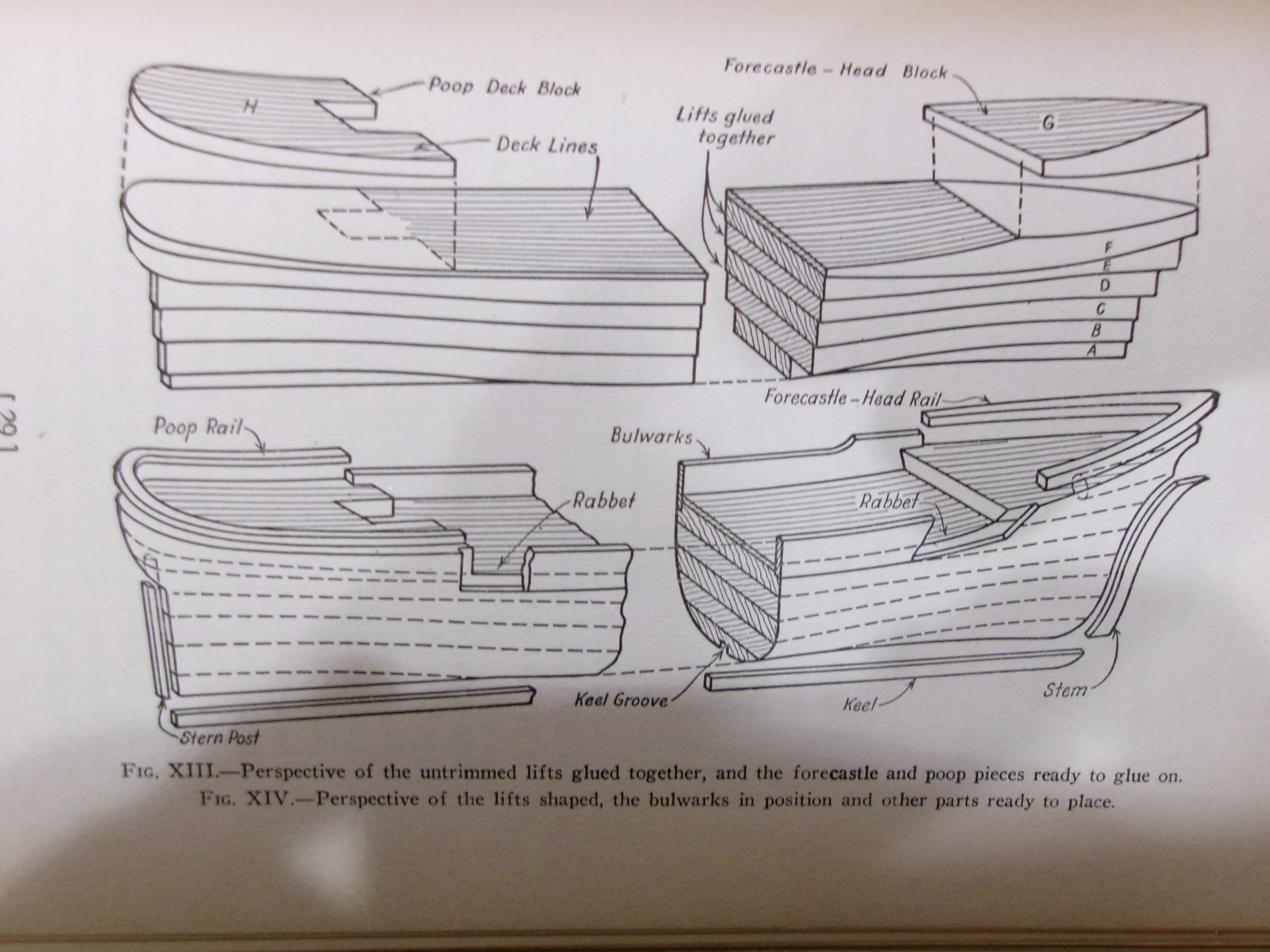
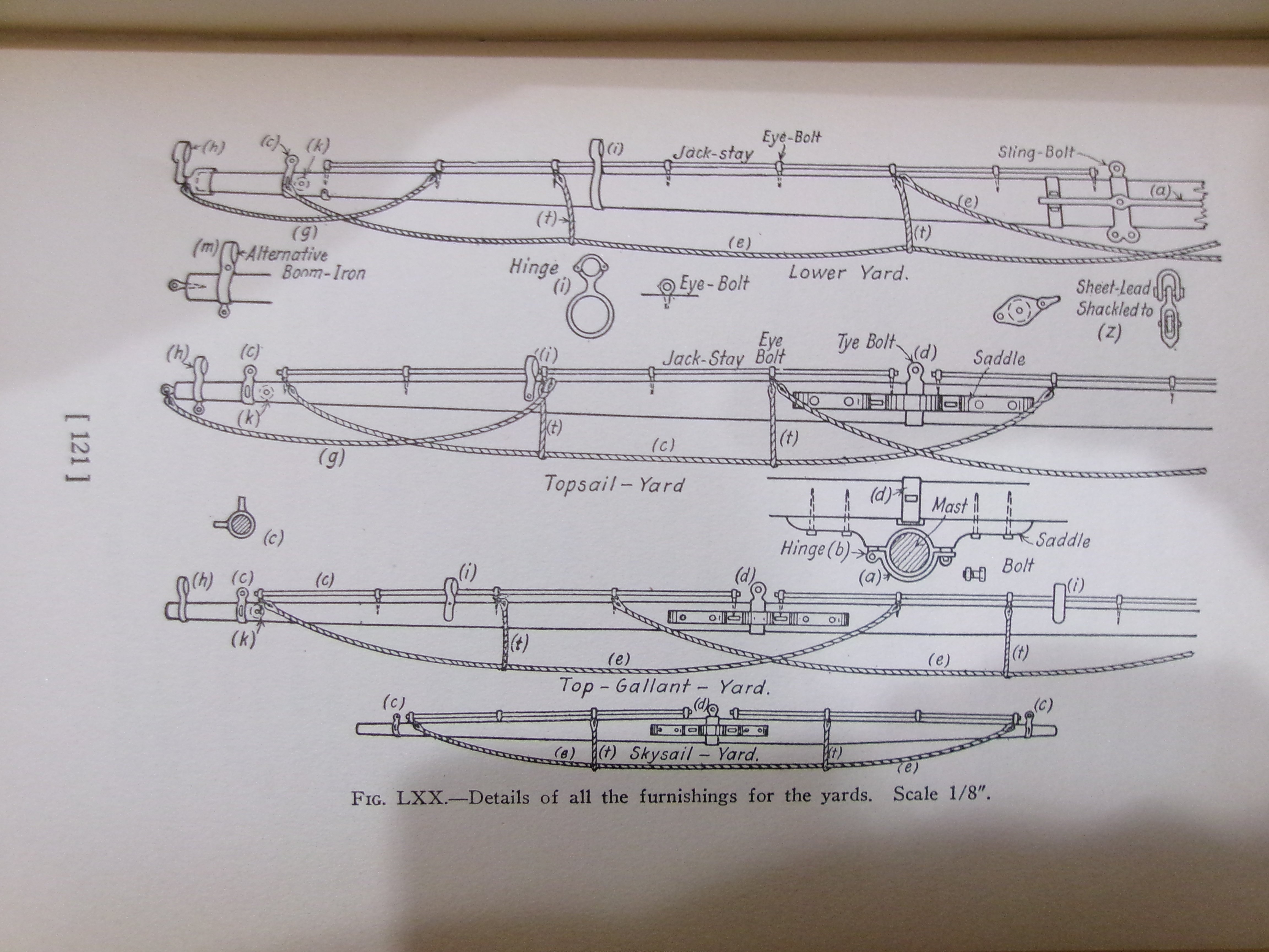
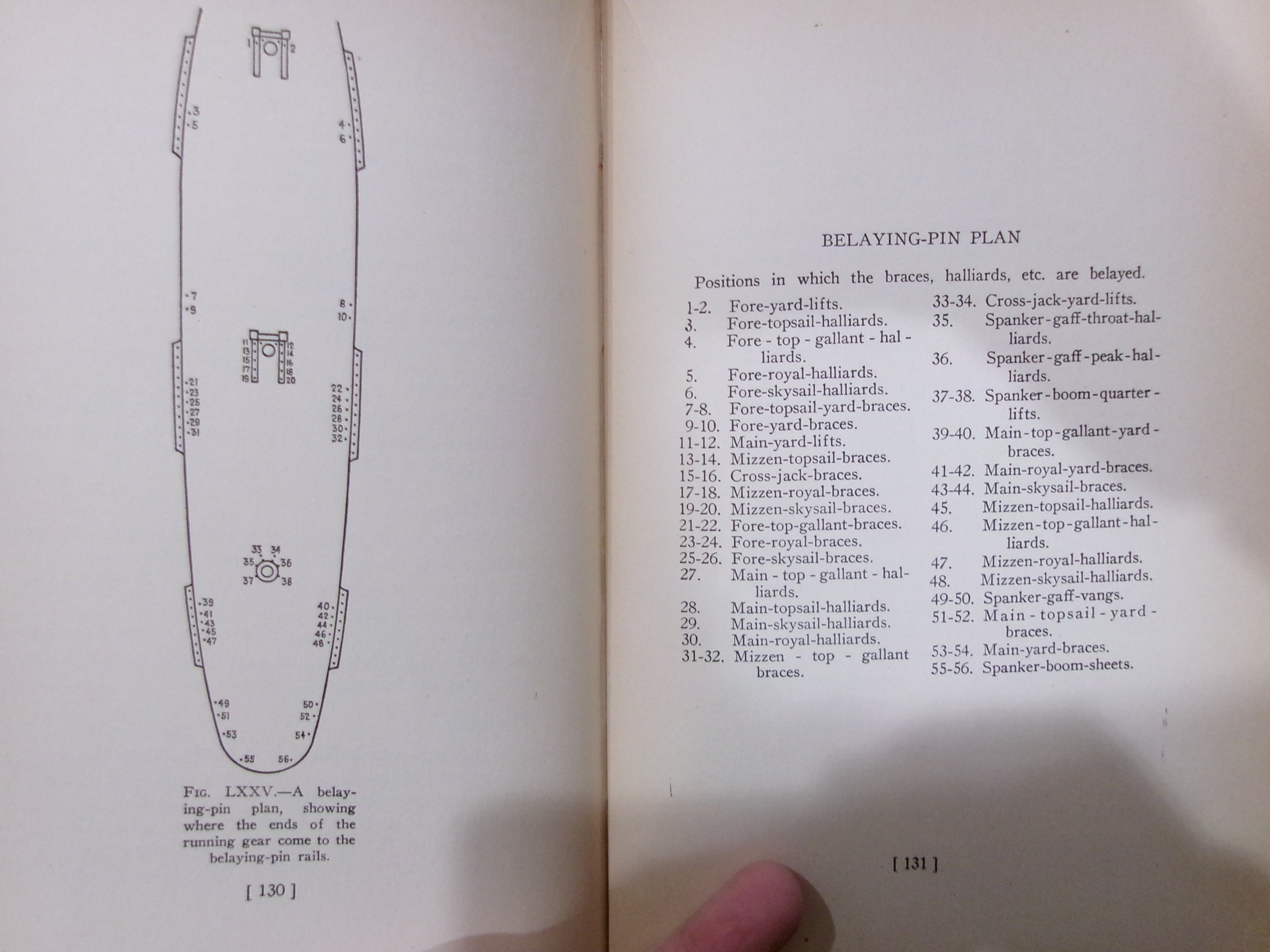
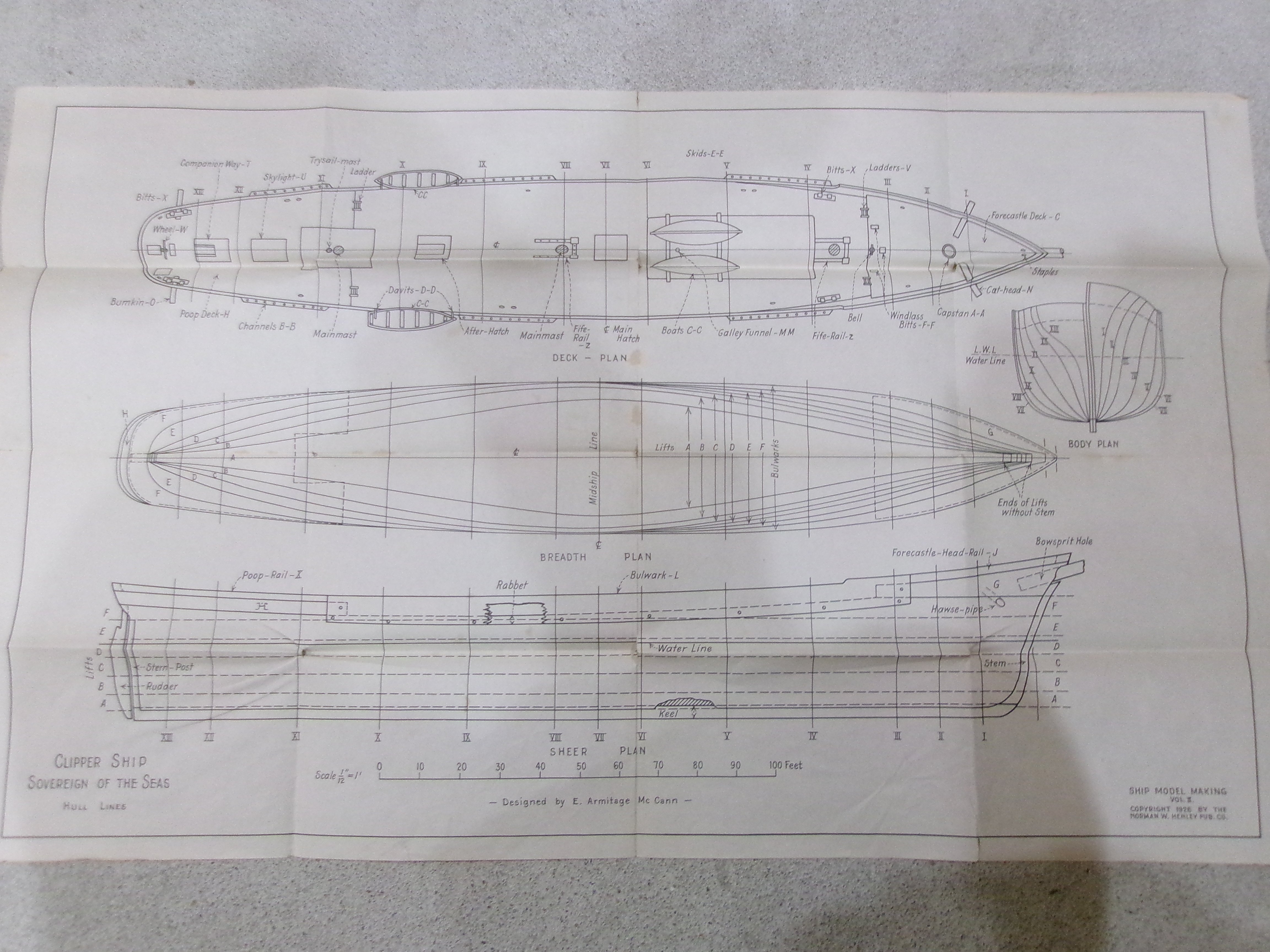
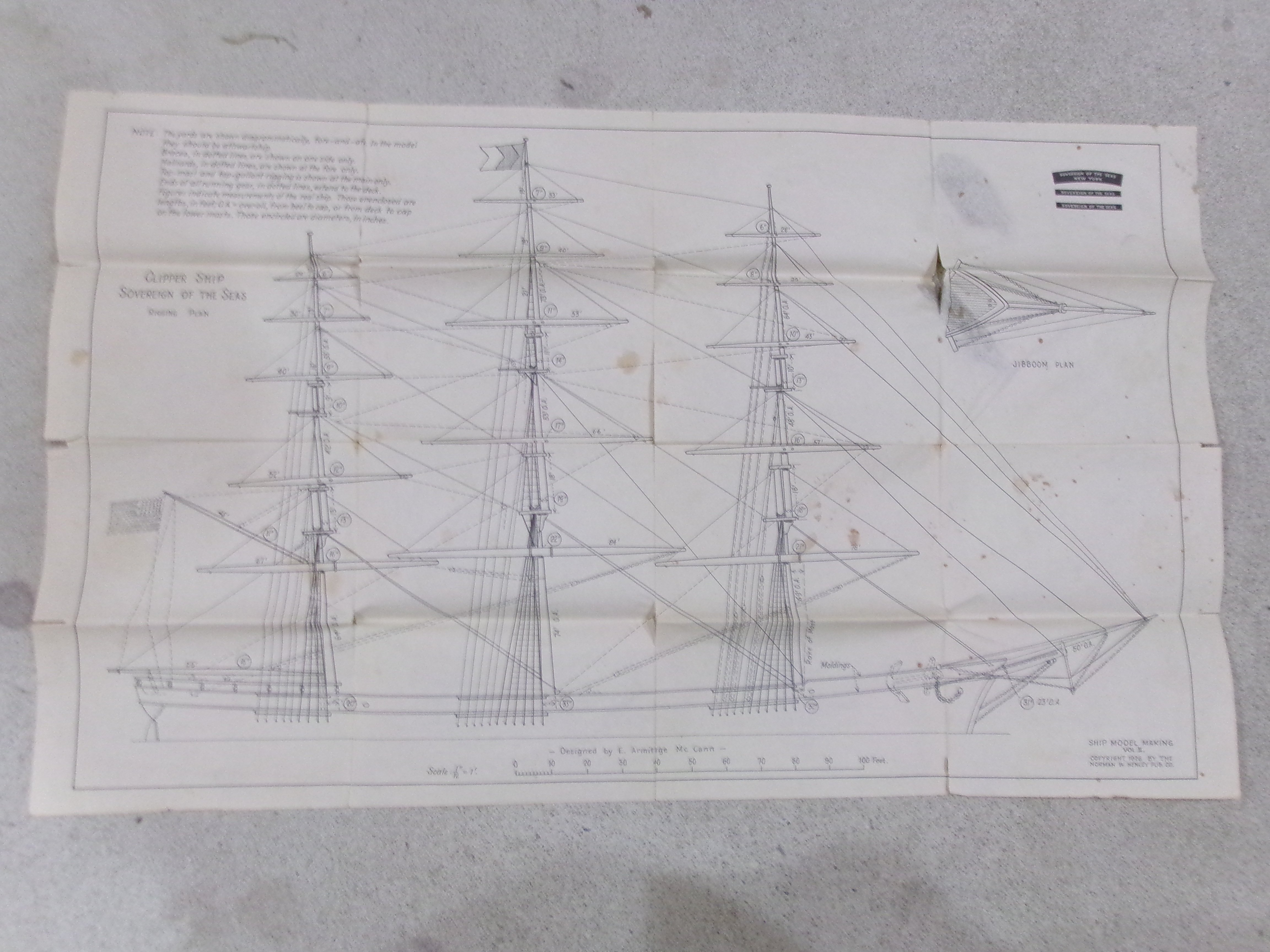
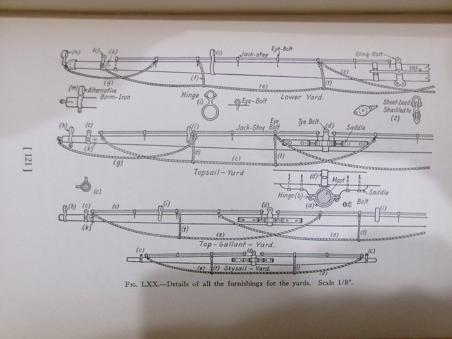
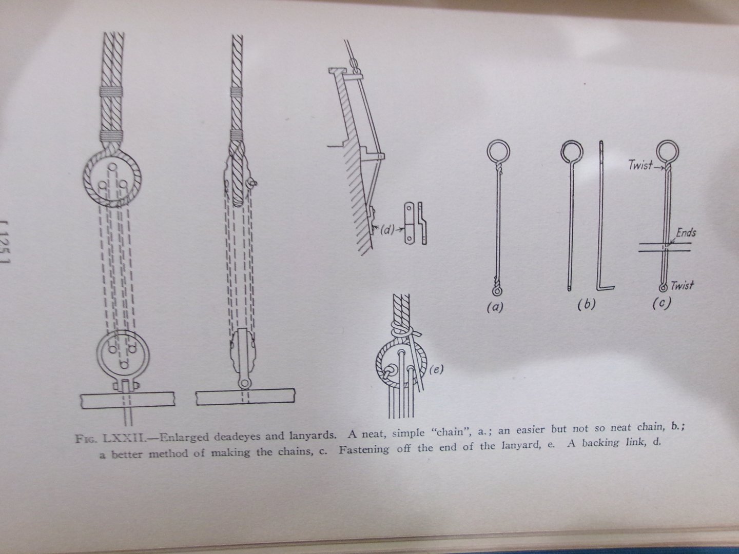
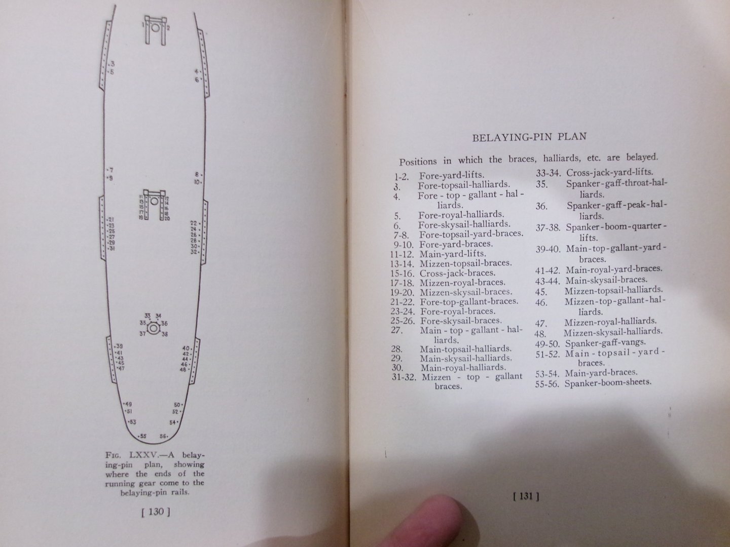
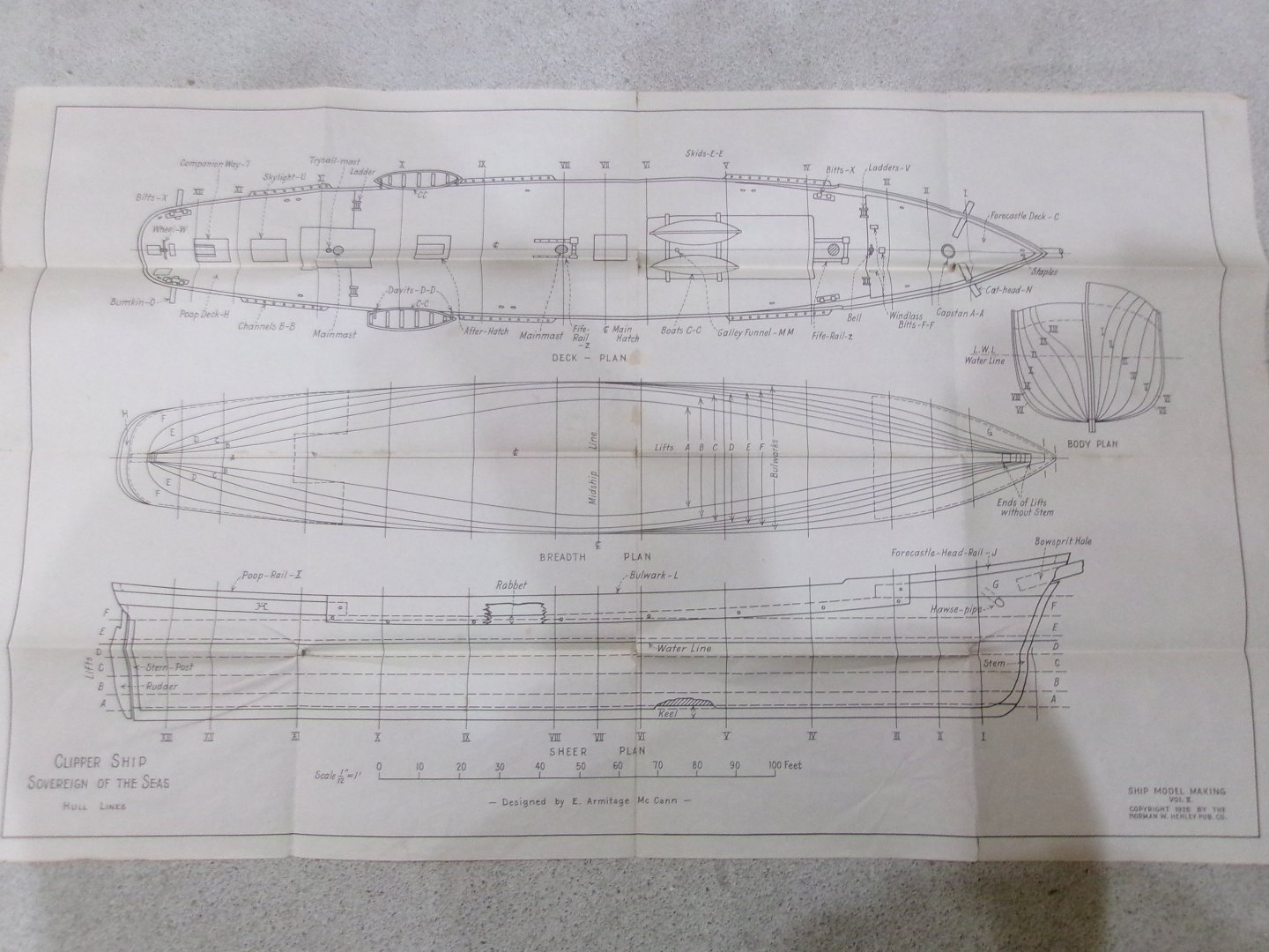
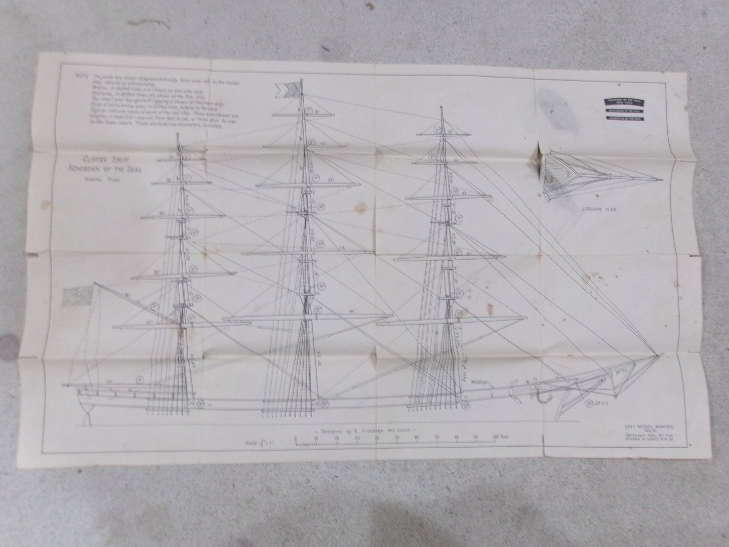
Good to start a new thread than to load up another log ... and I'm wondering if the title of the new one should be tweaked a little - rather than to search for the 'oldest' ship modeling book, maybe it could be a review of any pre-1950 'how-to' book (just a thought). Regardless, I just received an original 1926 copy of Ship Model Making (vol. 2 on the clipper Sovereign of the Seas) - a famous McKay ship) by E. Armitage McCann (through Abe Books on Amazon). I'm impressed at the amount of useful information in this book - not just for the 'scratch' builder it was intended for, but also for those getting into (or renewing) an interest in model shipbuilding today - with the advantages of the latest in ship kit technology. There a lot of 'nuts and bolts' talk about how to go about model ship making (for a clipper, at least, in this book - but transferrable as well) - including nautical terms and many illustrations/diagrams. A weakness may be a shortage of 'detailed' wood modeling techniques to actually craft many of the features illustrated ... but this was in 1926 when many 'handyman' skills were common (and expected) of boys and men. There are reasonable simplifications in the rigging, and a fairly clear layout (in comparison, the Cutty Sark rigging in the Airfix scale series of books can drive a modeler nuts, without a great deal of studying/interpretation and jumping around). There is a concise history of the subject ship herself, and a pair (checked in advance on my copy) of large folded plans in a pocket in the back hard cover ... very nice. Due to the date of printing, the paper is increasingly fragile due to the acid content of early 20th century publications - so care in handling is needed. There are Dover re-prints of this book (less the large plans ... 'not sure if they include reduced versions) ... but possibly subject to 'later' copyright of the Dover edition - an 'ah-ha' moment, as the 1926 book IS now in the public domain. Thus it can be copied by any means and used at will ! So I'll add just a few of the 1926 book illustrations as samples: I LOVE the 'layer cake' method of roughing a solid hull - its one I have done successfully myself not long ago on Thermopylae, although I found carving easier with more layers - and the thickness of the layers becomes thinner towards the keel area.


-
New To Model Ship Building
Snug Harbor Johnny replied to MaxnCookie's topic in New member Introductions
Greetings, mate ! You should have fun perusing all the great build logs on MSW. -
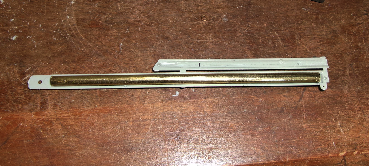
'So sorry about the mishap, but it seems an Achilles Heel of the Revel Cutty (and Thermie) is the dolphin striker and the Cathead extensions ... and even the bowsprit itself. Well, to be fair, ship models are by nature somewhat delicate - and many things can get broken (like if you drop it). In the photos below, I put a piece of brass tubing (after squeezing into an oval shape when seen from the end, since the void in the Revell bowsprit is not fully cylindrical) into the bowsprit as reinforcement (some just glue in sprue to do the same thing). I decided to make a jib out of wood (scrounged from a 'parts kit') because the wood is far less flexible than the plastic one in the kit (but still breakable). The best thing I thought of for the dolphin striker was to cut one out of brass sheet with a jeweler's coping saw ... 'outside the line' for a rough cut, but easily filed before fully cutoff - then the bottom twisted 90 degrees. The plastic bowsprit end was drilled deeper to accept the brass striker. A few other fittings were cut out for the jib, and I'm OK with the result. I'll do something similar for the cathead extensions.
-
Recommended First Machine
Snug Harbor Johnny replied to vvvjames's topic in Modeling tools and Workshop Equipment
Don't forget a jigsaw ... and you don't need an expensive one. Mine is a handed-down Dremel mini jigsaw. Its noisy, but does the job cutting out small parts. -
Help to assemble AMATI chain plate 4090/05
Snug Harbor Johnny replied to Johnny Mike's topic in Masting, rigging and sails
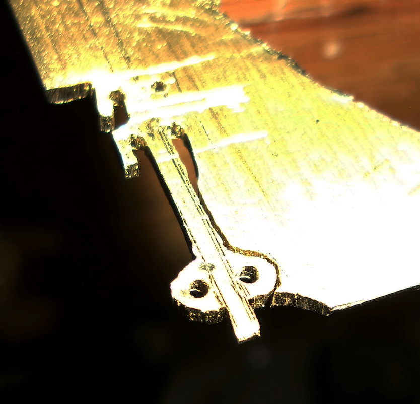
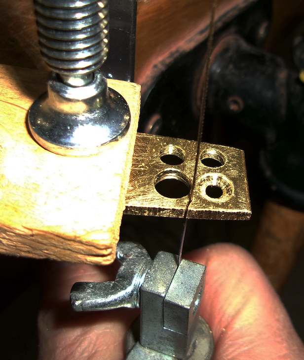
If you haven't tried annealing, then you haven't "tried everything". Annealing the brass 'ears' should work, just as marksmen in the North-South Skirmish Assn. (N-SSA ... I was a member for 30 years) firing repro brass cases for Henry Rifles or Spencer and Burnside Carbines experience work hardening around the rim (or formed shoulder of the Henry) cartridge after crimping and subsequent firing on a target range. Each case was stood-up in a pan of water (dimmed lights in the shop), then the case mouth was heated with a propane torch just until the slightest glow was seen from the metal, then the case was tipped into the water to quench. Actually the quenching was not needed to anneal, since mere heating to 750 degrees F accomplishes that, but temperature is hard to judge - so the metal will just start to glow orangey around 800 - 850 degrees degrees F. Quenching prevents overheating the brass, which can change the composition of the alloy by burning off some of the zinc. You can easily anneal the ear end of the chainplate with a candle flame ... Hold the long end of the chainplate with needle nosed pliers, hold the ear end in the yellow of the candle flame (near the end of the flame) until you see the brass start to glow (dimmed lights makes observation easier). Then immediately quench the hot end of the chainplate in water, dipping the entire piece into, say, a glass of water while still holding with the pliers. The 'Bob's your Uncle', you should be able to bend the ears open enough to insert the wire ends of the enclosed deadeye into the holes in the ears - then bend them back and they should not break. Only bend once, as this process work-hardens the brass. -
Should i get the constructo hms victory
Snug Harbor Johnny replied to Nickk's topic in Wood ship model kits
Another thought ... There have been many builds of certain ships such as HMS Victory, USS Constitution, Cutty Sark, etc. These are well trod paths, and I'd likely be more interested in building a project done less frequently - if only for the relative novelty. The tips and techniques found in MSW builds are largely transferrable, at least to other ships near the period of the build examined. -
Should i get the constructo hms victory
Snug Harbor Johnny replied to Nickk's topic in Wood ship model kits
Ahoy, mate ! You don't say if this will be your first ship model, or if you have prior experience. If the former, a Victory may not be the best place to start. I think there is a MSW topic on good "first models" to consider. I didn't find a review of that kit on MSW, but there was one unboxing and one review on you tube. Per an A.I. summary of my query on your primary question: The Constructo HMS Victory kit is a large, budget-friendly option, praised for its size and decent wood quality but heavily criticized for its poor, basic instructions, often requiring experienced modelers to supplement with other guides or kits for better detail, making it a mixed bag for those seeking accuracy and ease, though it can build into a nice display piece with significant effort. Pros: Large Scale: A big kit (around 1:94 scale, over 3.5 feet long) offering a substantial build. Good Value: Generally considered a great price for the size and wood included. Decent Materials: Wood quality is often good, with nice grain, though some pressed wood parts exist. Potential for Detail: With extra effort, it can become a good-looking model, especially the framed hull. Cons: Terrible Instructions: The biggest drawback; described as inadequate, basic, and among the worst in the industry, earning a low score. Lacks Accuracy/Detail: Compared to higher-end kits (like Caldercraft), it's simpler and less detailed, with features like deck camber often ignored. Advanced Project: Despite its simplicity in some areas, the lack of clear guidance makes it challenging, requiring an experienced builder. From the unboxing, there are some wood parts not laser cut, and you have to cut them yourselves. Other wood parts are 'pressed' (diecut?) but may take care in getting loose. The bulkheads appear to be laser cut. There are a number of plastic fittings, but also brass ones. There have been "simplifications" in the detail, so in the photo below from a reviewer (who said he found the kit difficult ... but persevered) it has the appearance of a better grade commercial pre-built model one can find for sale. But if the price is right, who knows what can be done with some effort.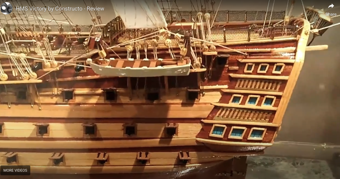
-
'Love the way its coming together ! 'Looks like the wood fillers in the hull voids makes for both a sturdier model - and one with less kinks or dimples in the hull. I'm watching with great interest. Thanks, mate ! Johnny
-
Revell 1:96 Cutty Sark after-market decals?
Snug Harbor Johnny replied to Terry Lawson's topic in Plastic model kits
I found that a thin coat PVA (polyvinyl acetate) bonded the wood veneer deck to the plastic beneath. The glue was applied to the plastic, allowed to get more tacky, then the wood put on top and pressed around with fingers. Then some cloth put over the wood, then a plank and some weight to evenly clamp. -
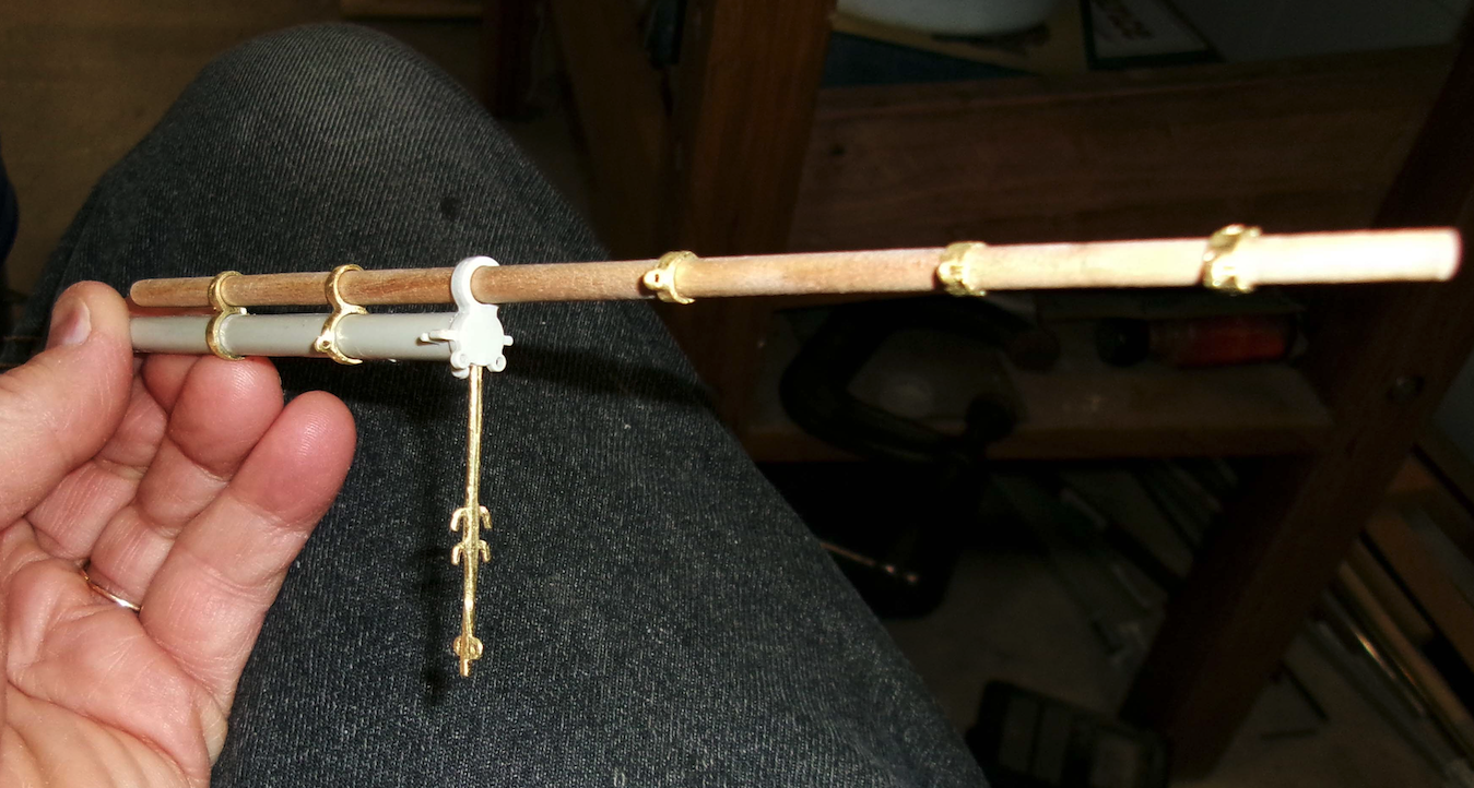
Your ropewalk is setup with a 'top' (juggernaut) that runs itself up to the geared end as the rope is made - similar to a full-size rope walk, but constrained by the side line guides. A large version I used to use at craft demos had a swivel on the far end to relieve excess counter-twist, while other versions use a crank. Whatever way, the product comes out about the same. After using Chuck's Rope Rocket (judging the amount of twist by 'feel' and distance each end moves on the two-step process), the scale rope length is 'whipped' by hand to normalize any twist imbalance (that removes any kinks), then I'll step on one end and pull out the rope in sections to stretch it out ... this 'sets' the rope pretty good. I use poly thread for permanency, so it is heat treated on a cookie sheet for 5 minutes in a 320 degree F oven. Cotton doesn't need this if stretched with moistened fingers. Old models rigged in just plain cotton thread can have deterioration, but laid scale rope of cotton should last longer ... but many (like me) are betting on poly for the long run. Linen rigging - like the old fly fishing line used by old timers - holds up very well, just as fine linen sails have done.
-
Ahoy, mate ! I once saw a private sailing ship out of Annapolis name 'Despot's Heel' ... Those who have lived in Maryland will get it.
-
"hope you have smooth sailing this time around, mate !
-
The build of the USS Tennessee used the sewing method to put ratlines through the shroud lines, then before tying cow hitches on the outer shrouds, the builder pressed each gap with a tool to put in a little droop to the ratline ... not much, mind you. If I remember correctly, dilute PVA glue was used to 'freeze' everything in place.
-
Revell 1:96 Cutty Sark after-market decals?
Snug Harbor Johnny replied to Terry Lawson's topic in Plastic model kits
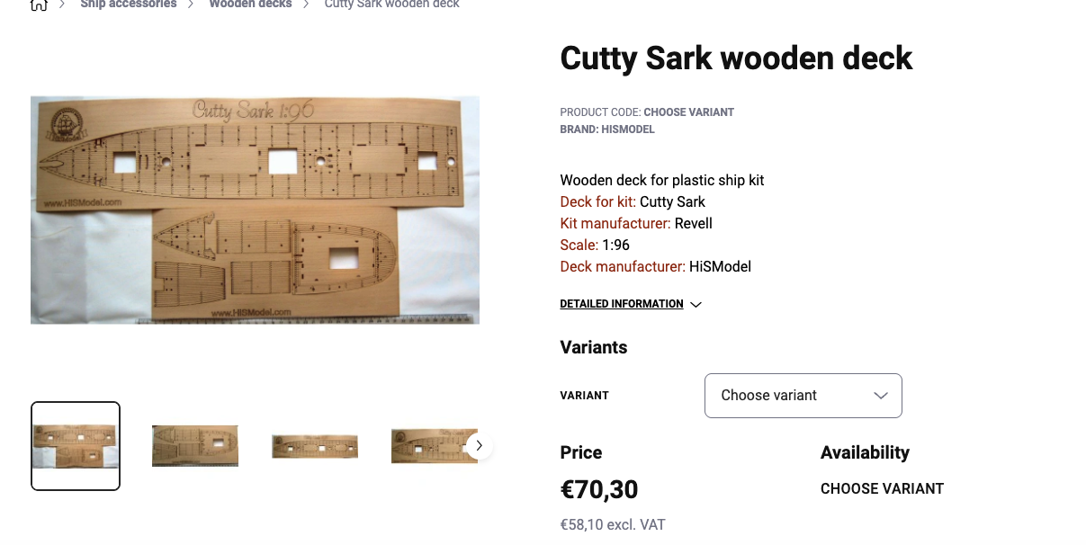
There is a supplier in Eastern Europe (Czech, I think) who runs H.I.S. Models (hismodel.com) , and he has a set of photo etched decorations on thin brass for both the Revell Cutty Sark and the Thermopylae. I ordered the set for the latter - along with the wooden deck in beech veneer (oak has a heavy grain that looks out of scale) that I found on EBay - so I ordered through Ebay. You can check if he still lists the items there if you prefer. H.I.S. does accept credit cards now (they didn't s few years ago when I bought the items, and thats why I went through EBay). The decoration set (quoted in euros) is about $25 USD, and shipping should not be too much ... but I have no idea what the tariff situation with that country is now. You can always contact by e-mail, and find out. The photo etching is delicate, but handled carefully and glued (presumably with CA) it has looked very nice on photos of those who have applied them. (I'm dragging my feet on Thermie, since I've done a second hull with authentic lines - not those of CS used in the Revell Thermie kit - in basswood at 1:110, but will used many of the 1:96 parts anyway.) The wood deck made for the CS kit is more pricy (something like $75 USD), but very nice. I inlet sections of the plastic deck into the basswood Thermopylae hull to serve as mast bases and also for the hatches and the deck equipment, then I used PVA glue to bond sections of the deck veneer to the entire deck. This involved (for my case) in cutting-and -pasting the oversized 1:96 deck to the 1:110 area. For the Revell kit, none of that is needed.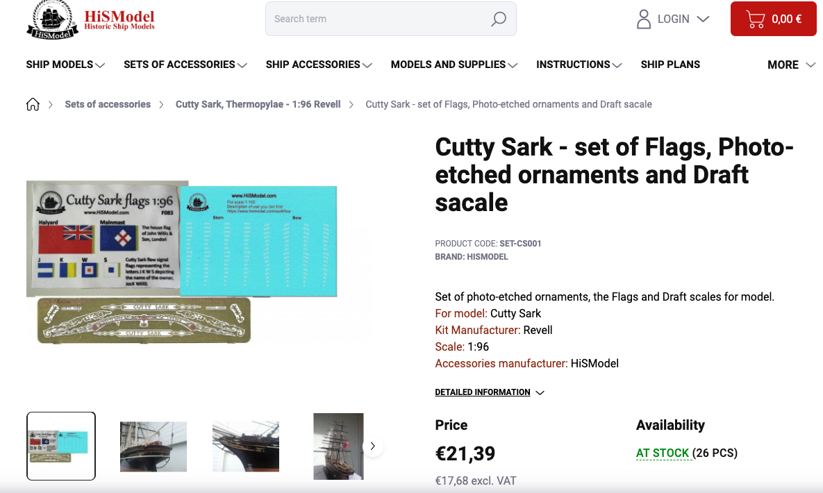
-
The difference between the last two posts is that the lower one (video) uses clove hitches all across the shrouds, which leaves the ends of the ratlines sticking straight out ... so when they are cut off after any glue fixes the attachment points, there is a little bit that still sticks out. On ships, the ratlines went around the outer shroud (as an eye splice) and were seized ... and for most this is too finicky. The post further up shows a cow hitch on the end shrouds (slightly different form a clove hitch), and the cow hitch has the end of the line terminating on the inside of the shroud. When cut off, the outside of the outer shrouds look better, the cut end of the ratline is on the inside adjacent to the ratline as if it were seized. Note that the ratlines are much thinner than the shrouds, and in the video they seem a little thick. A main shroud may be, say, something like 2" on a full scale clipper or warship (somewhat lighter aloft), which works out to about .040 scale rope at 1:48, .030 at 1:72, and about .020 at 1:96 ... of course, shroud size will vary depending on the size and type of ship (a range of 1.25" - 2.5" ?). Ratlines were around 1/2" in diameter (+/-), so that would work out (respectively) at the above scales to; .010, .007 & .005". This means the on a 1:96 model one would use a single thread of Guttermann poly (or Metrosine thread) for the ratlines (thus sewing through the shrouds with a fine needle is an option, if you don't want to fuss with knots), whereas .010 fine scale rope (spun from 3 strands of thread) seem OK for 1:48 or 1:72.
-
'Always room for another crewman ! Welcome aboard !
-
This gives me an idea ... since the hull below the waterline has the most 3-D shaping the paper has to conform to, on a completely filled hull like catopower's, one could forgo papering that area (least seen anyway) - simply seal and paint the color of antifouling paint (typically a rust red). From the waterline up the paper would be used (excepting some features like optional metal gun barrels and metal railings). Most stuff topside come in flat planes or simple curves (there are some exceptions) .. so once past the underbelly, Bob's your Uncle !
-
It is most interesting to see the use of balsa to fill and stiffen the framing of a card model ... the very thing I want to do (eventually) on the USS Baltimore (CA-3 1890) 1:200 from Heinkel models. There is a complete build on MSW with many tips and innovations that can help any builder of a steel warship: https://modelshipworld.com/topic/37247-uss-baltimore-ca-3-1890-by-jsk-finished-heinkel-models-scale-1200-card/#comment-1066761 As for availability, they sold me an economical download version for less than $20 paid by credit card, and I was able to print it out with no difficulties. As for color and size, I imported a renamed duplicate of each file into Photoshop (not that I'm used to that very complicated - and powerful - program) and was able to do simple enhancements to the color balance and contrast by tweaking the sliders for those by clicking: Image - Adjustments - Color balance (or Brightness/contrast), then I saved as a jpeg file. Buying a download from the designer gets around all the shipping and tariff expenses (besides costing less than a physical kit). Of course, one must obtain the needed thickness of card (art board) stock to glue the paper (you print out) to, then the cut pieces out yourself. A good art store will have various thickness of paper products, and I went to Blicks for mine (now stored flat under our bed ... with the Admiral, out of sight is out of mind). Parts of the hull (fore-and-aft) are in two pieces meant to be printed on 8 1/2 x 11" standard paper (higher 'pound' weight stock is better) to make about an 18" model. But by dividing the images in Photoshop (by sizing duplicates) and printing the "halves" (with overlap so no individual part is cut) at the largest scale that would fit the length of 8 1/2 x 14" paper, I was able to get pieces that will make a 24" model (about 1:150 scale) that will be easier for me to fiddle with. I imagined that using balsa to fill the large voids in the paper framing would: 1.) stiffen the hull and make it easier to work with, attach structures to, and even pin into the substrate enclosed by the paper applied to the frame; 2.) give the model a little 'heft' so it isn't featherweight and will be more robust; and 3.) provide great lines of the hull, once sealed, that the paper can be glued to - and will more evenly conform to (perhaps with slight moistening by a water based glue. This means less creasing or kinking of flat paper trying to assume 3 dimensions. The builder of Baltimore didn't like how the recurved area in the upper stern came out, and if there was a solid substrate, the paper could have been molded enough to look a lot better. So as Chris advised, getting a smooth surface with filler will prevent those divots and irregularities from 'telegraphing' through the applied paper. 'Love your progress thus far, and I'll be following your progress as you go along. Savor each phase of the build and take whatever time is needed to go from step to step. Clear sailing ! Johnny
-
Indeed, A.I. can get it wrong. I asked what the draft of a C&O canal boat was, and the A.I. 'summary' said 6 feet. I knew this had to be wrong, because I recently visited the Monacay river aqueduct on the C&O and measured the trough depth (from half a foot beneath the top of the capstones) of 5' to the material added to the bottom during the maintenance done in 2005 - which added half a foot to the original base. Thus the range of water depth in the aqueduct available (though deeper in the earthen sections) when the canal was in use was 5 to 5 1/2 feet. So I did my own search to find the original specifications in use between 1873 and 1924 (the year of closure) and found that the largest boat was limited in loaded draft to between 4' 3" and 4' 9" - consistent with my measurements of the stone passage. A.I. was likely stating the distance from keel to gunwale (6'), because the specifications for minimum draft was 6" to 11". The barges were merely wooden boxes with slightly rounded ends, so an empty barge rode high in the water, and was known as a 'lighter'. Due to some low bridges, the overall height also had to be limited. Still, you can get many good leads from A.I. - but you still have to use human intelligence plus logic to 'filter' out bad info. It also depends HOW you ask a question in a search, so multiple queries put in different ways can lead to useful results.
-
Looking for ideas for work area
Snug Harbor Johnny replied to Desertanimal's topic in Modeling tools and Workshop Equipment
You can consider adjustable shelving as seen in a tight end of my workshop. Found at most 'big box' home stores, the vertical rails attach to a wall (preferable screwed where there is an underlying stud), then metal arms (several lengths are available) clip into the verticals at the levels you choose (and they can be easily changed) - then the shelving made for the arm length chosen simply lies on top of the arms (don't space the verticals too far apart). You can put stash kits, supplies or whatever on the shelves ... and this idea can be used for finished models in any room, where acrylic sheeting is hung from the shelf above (drill holes along the top of the acrylic to fit over hooks screwed into the edge of the upper shelf) and the bottom of the clear sheet rests against the lower shelf. That, plus small sheets on any free shelf end, will keep out most of the dust - yet permits easy access to the model. Below my shelves is a home-made tall bench (plywood top and 2x4 legs & under frame) where I can work standing. Many find sitting for too long can cause back strain, so at least half the work I do is standing - also efficient in a tight space.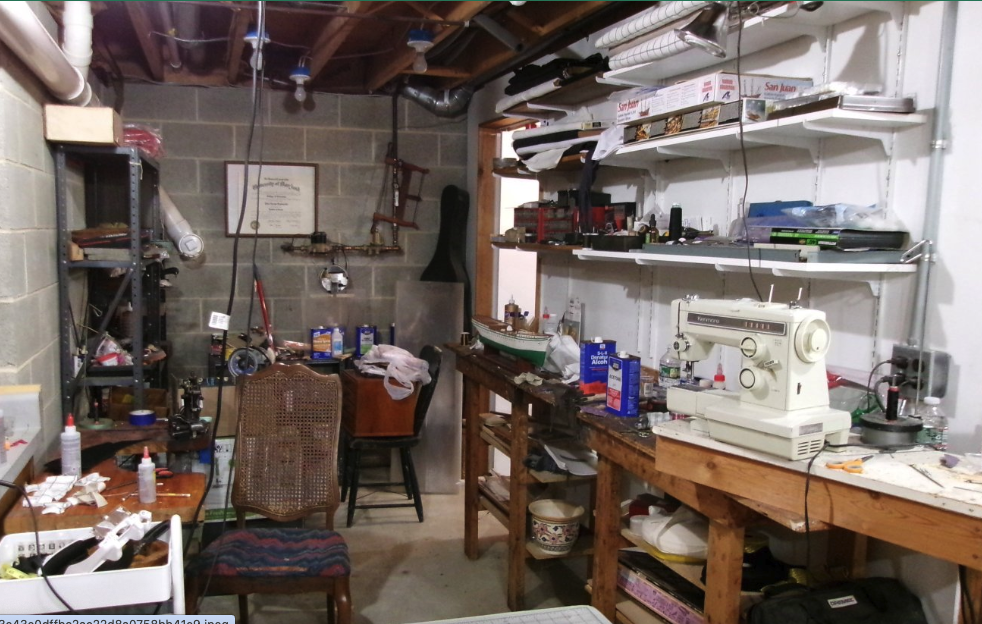
-
'Affordable' kits often have many compromises ... and even outright shortcomings. That's where doing research and buying better aftermarket fittings, buying or making scale rope, etc. will upgrade a model - but at a cost. But like painter Bob Ross said, "Its your world ... you can do anything you want."