

My Fathers Son
-
Posts
193 -
Joined
-
Last visited
Content Type
Profiles
Forums
Gallery
Events
Posts posted by My Fathers Son
-
-
Not really, it's just how the sit because of the knot.
Work out how they need to present the orientation. The lower deadeye has to have a single hole at the lowest part. So when attaching the line run this around the deadeye and instead of noting the two ends, use a much lighter line to bind the two ends together.
Once installed, the lines need to be bound to the mast in the same order as they sit on the platform.
It will still not look right until you do the rat lines to pull them in line.
I really like your dedication to being fully scratch built including the components.
I have to recognise that this is outside my current capabilities and accept that I have to source these for Cutty and Thermopylae.
Simon
-
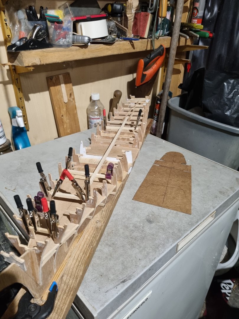
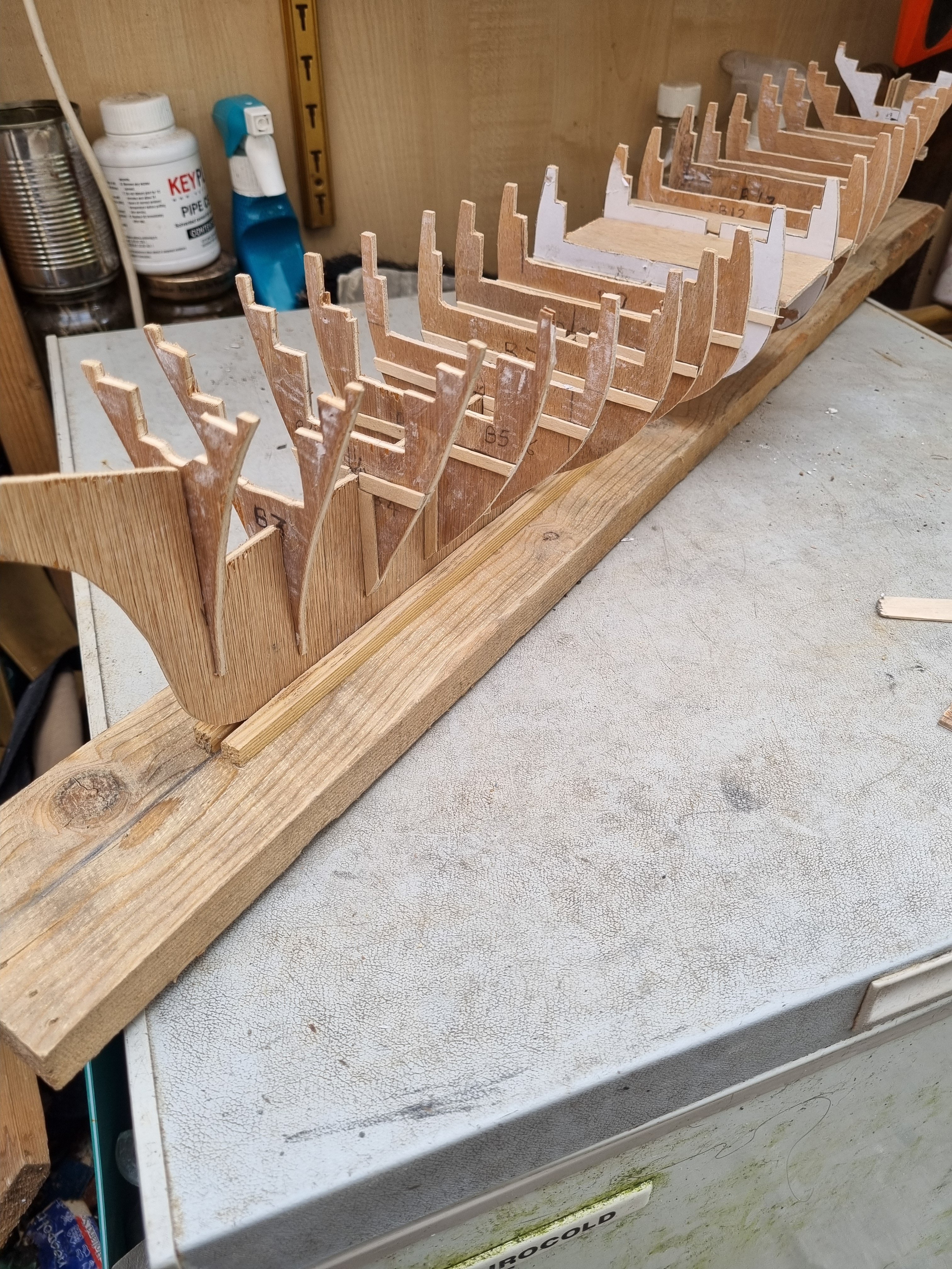
So I have been working on getting the templates set up for the main deck.
Having got the general shapes sorted out I can set out the locations of the various items that come through this deck. The mizzen location is sorted for this level. However, the Fore and Main masts are located on the false deck but I now have to calculate the location on the main deck taking into account the degree of rake of each mast.
I will clean up the pencil marks on these templates and redraw some guide lines for the final ply deck to eradicate the errors on the templates.
The more observant will notice there are a few bits of damage to the tabs on the frames. Two down to my heavy hands and the other two down to my four legged assistants.
- davyboy, Snug Harbor Johnny, Baker and 3 others
-
 6
6
-
-
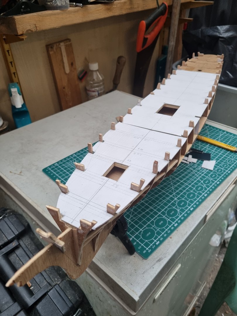
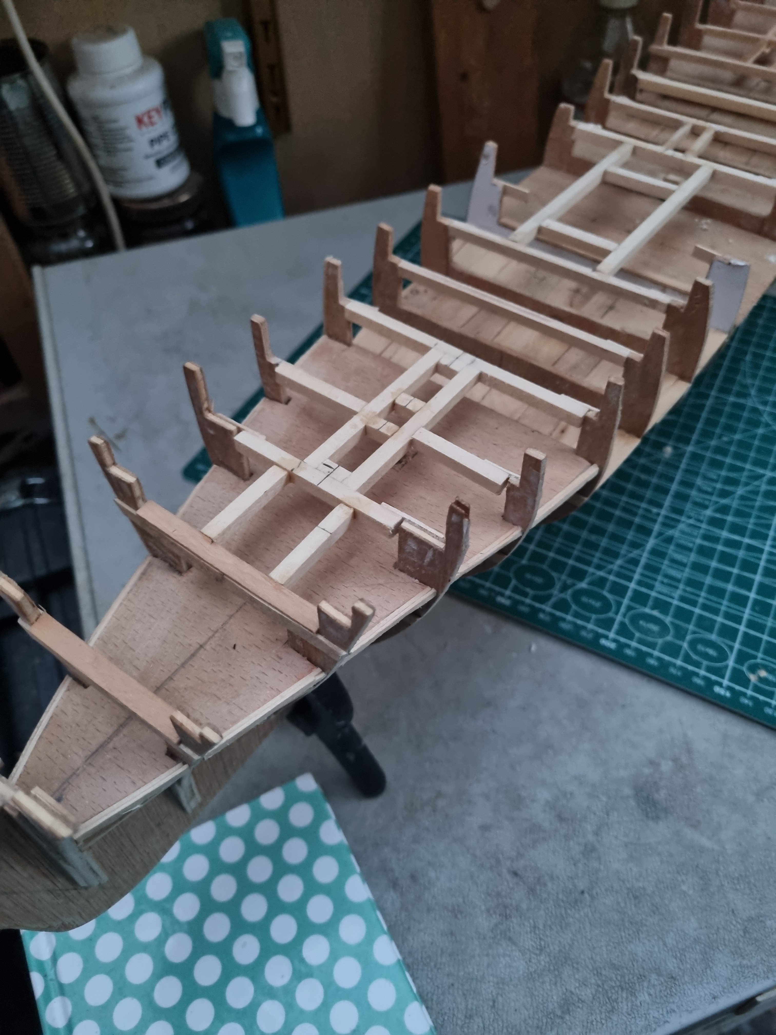
Well, I have roughed out the plan for the forward hatch and it's a bugger. It intersects frame 5 and as 6 is already compromised I am. Louth to do that to 5 as well. A temporary mast is in place so I can be sure it is vertical and has the correct lean aft, set at 86 degrees.
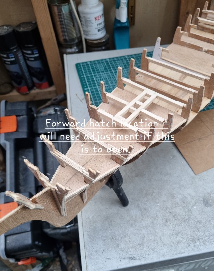
Photos as promised.
I should be OK with the main hatch as the main mast is immediately aft of frame 11 and I have not set out the beams 10 through 12.
Simon
- davyboy, Scottish Guy, GrandpaPhil and 3 others
-
6
-
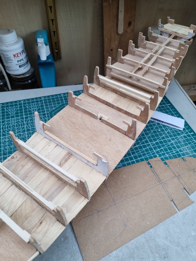
Worked on the deck beams again this evening and was under the impression that I had finished the fore section. I was aware that I would have to design a frame for the central hatch but I had forgotten the forward hatch. It looks like it's between frames 5 & 6, in front of the foremast so I should be OK there.
On the other hand it looks like the central hatch spans 11 & 12 forward of the main mast. I need to take the dimensions for all these and rough out a cunning plan.
Actually getting to construct this is fun but can be quite challenging.
I promise photos tomorrow.
Simon
- Scottish Guy, Baker, Keith Black and 1 other
-
4
-
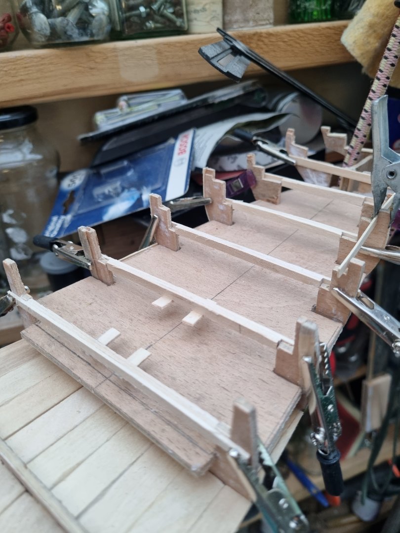
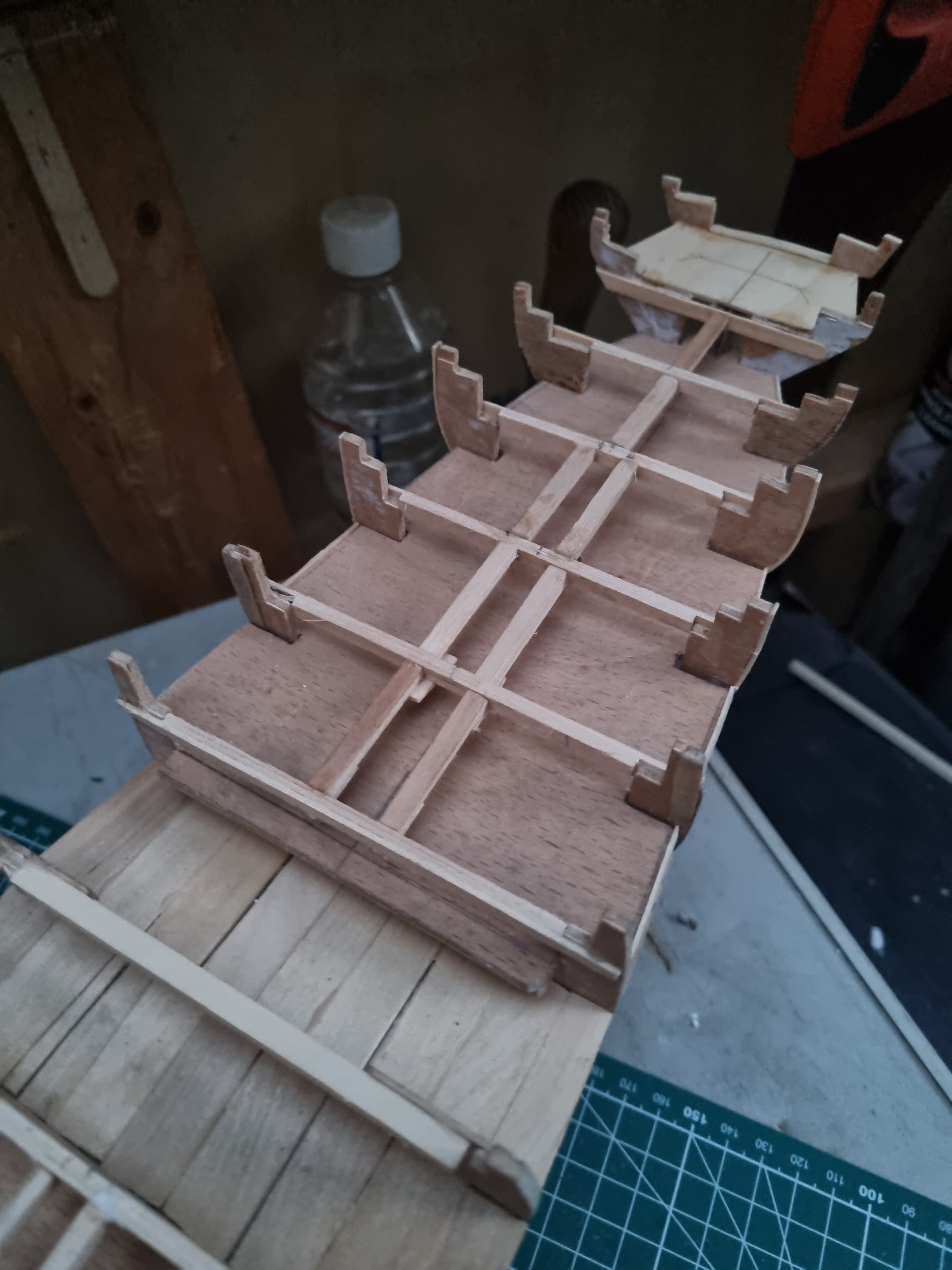
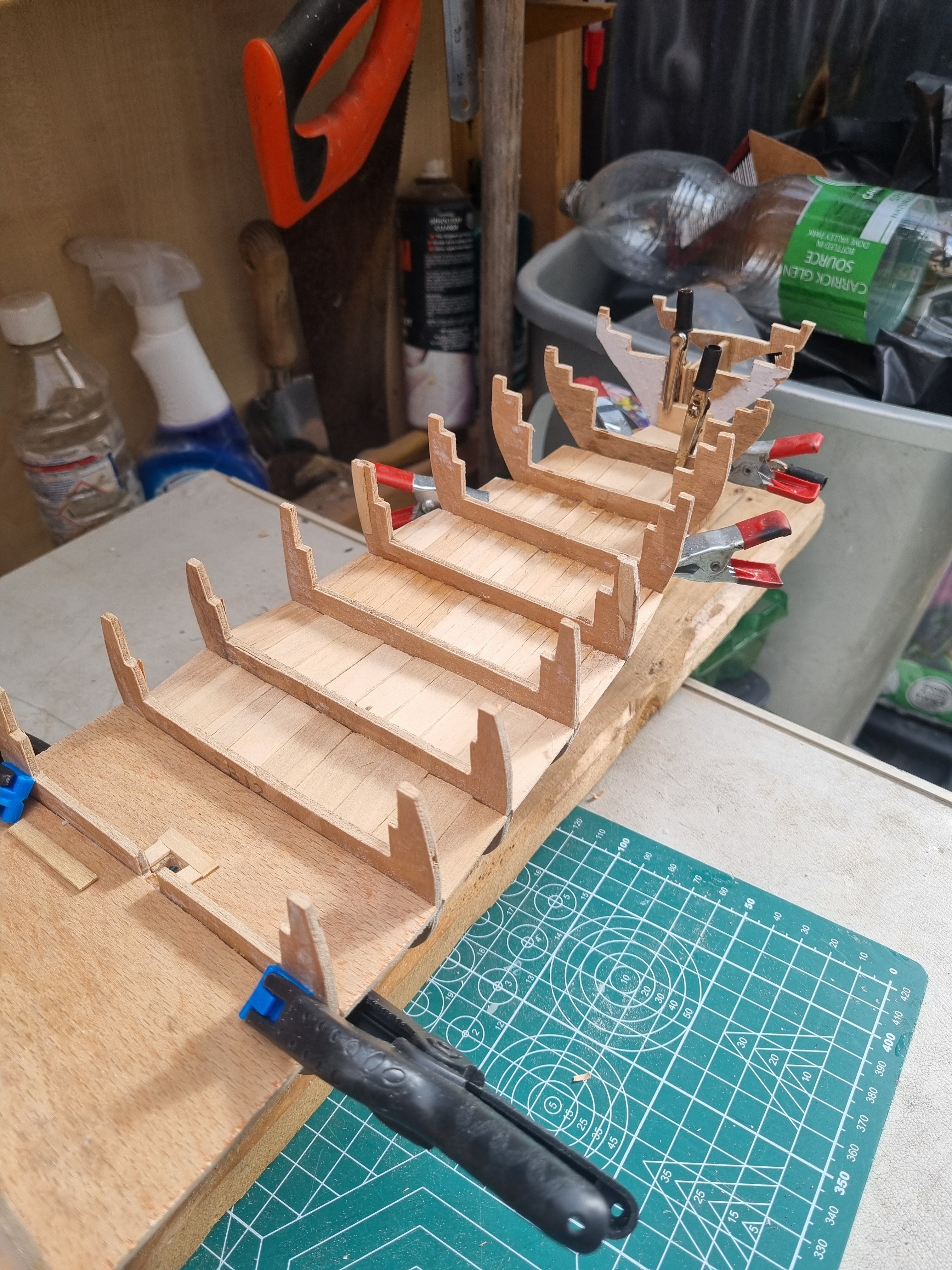
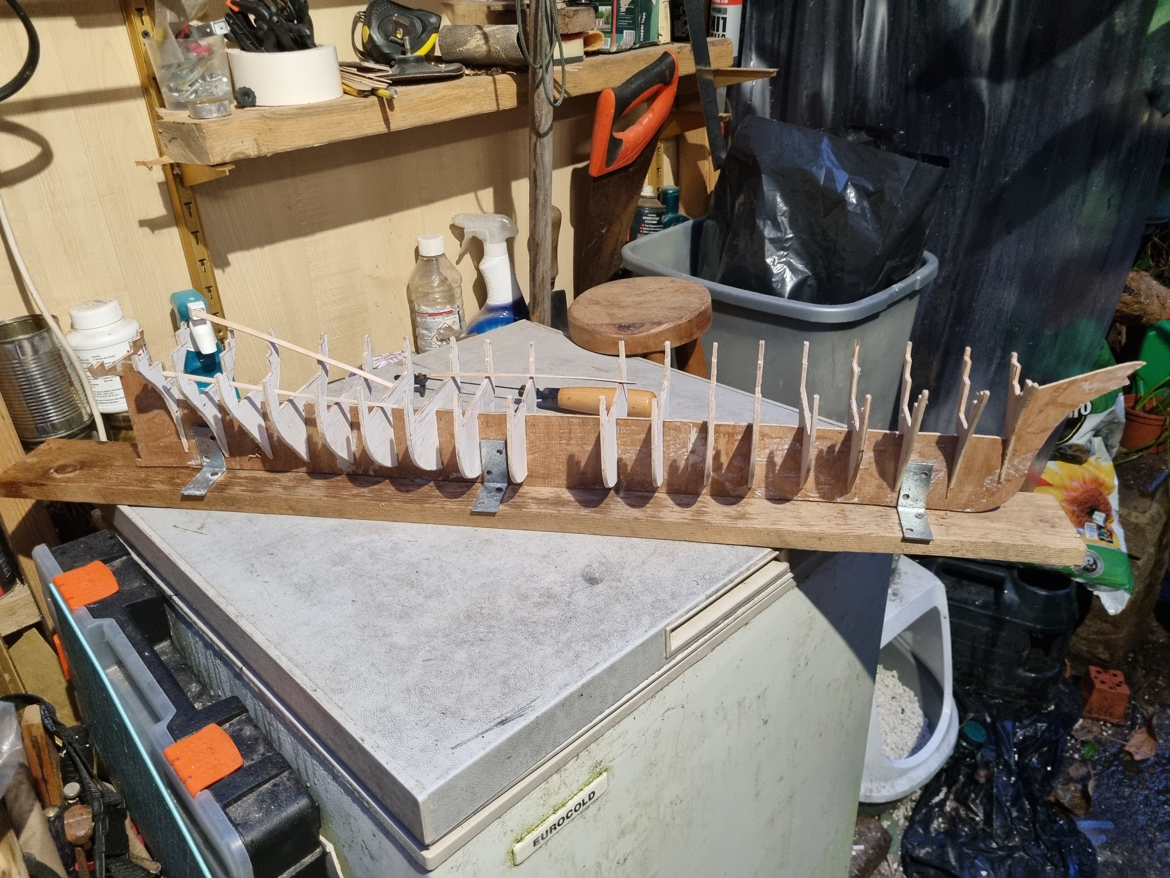
Worked on the cross beams again this evening. They are lining up nicely but I need to work out where the the hatch entrances will be located so I can set up frames for them.
All three masts will clash with the cross beams in some way so I will be doing the same thing for them.
Cross beams that might be visible through hatches are in new 3/16 square bass wood but the rest will be laminated coffee stirrers.
You can see a cardboard stencil I am preparing for the aft section of the main deck.
Simon
- Scottish Guy, berhard, Baker and 2 others
-
5
-
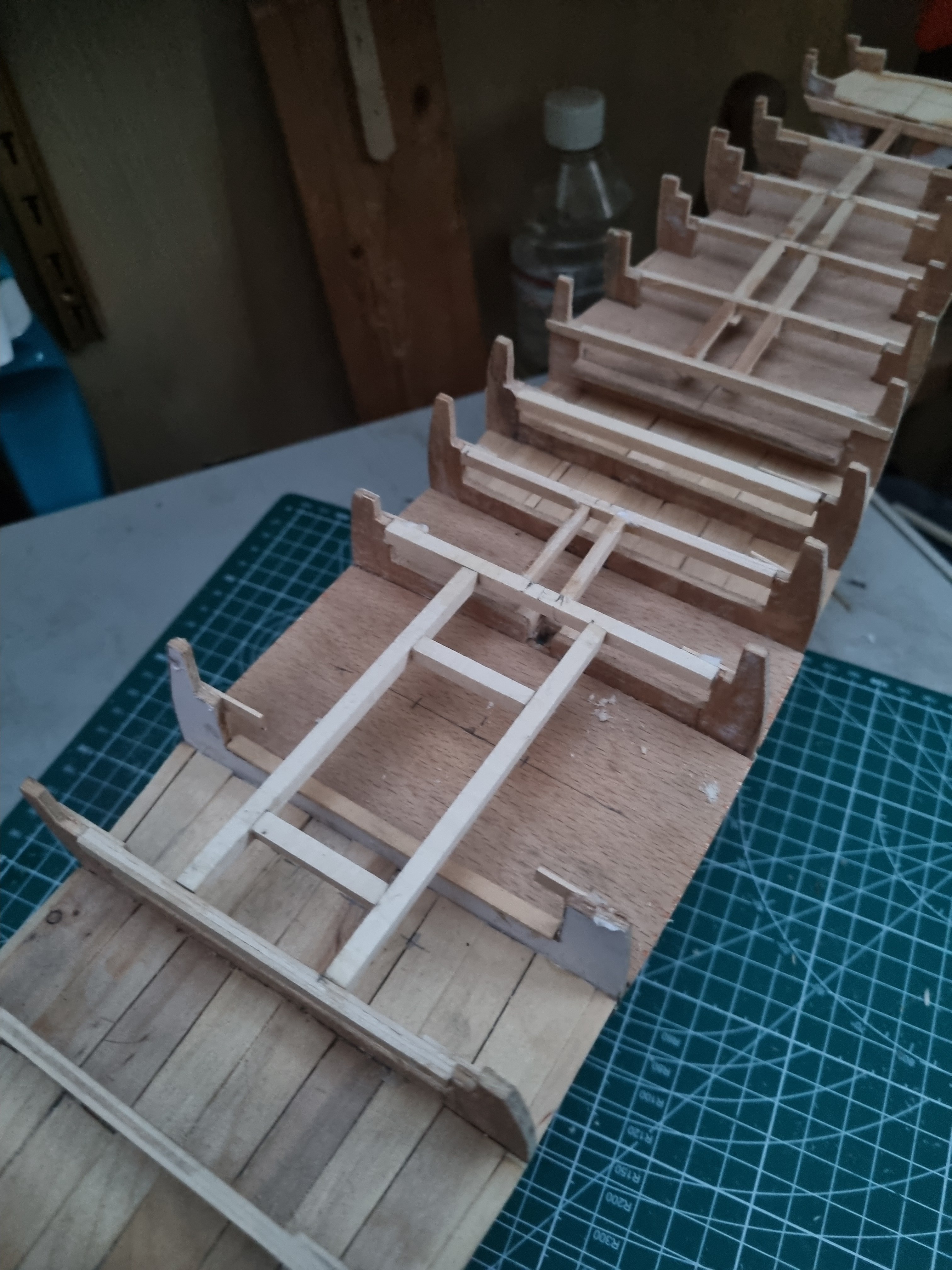
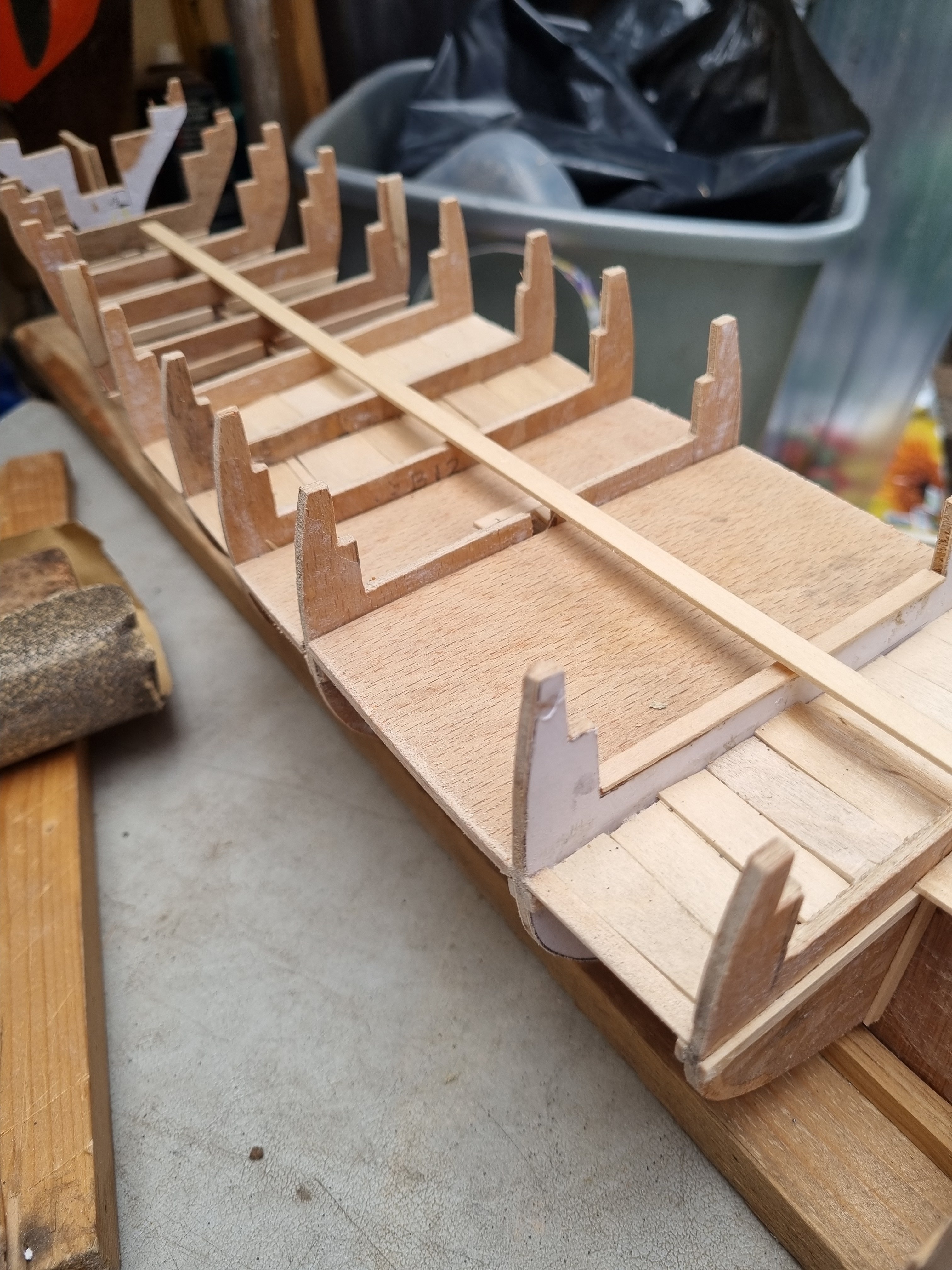
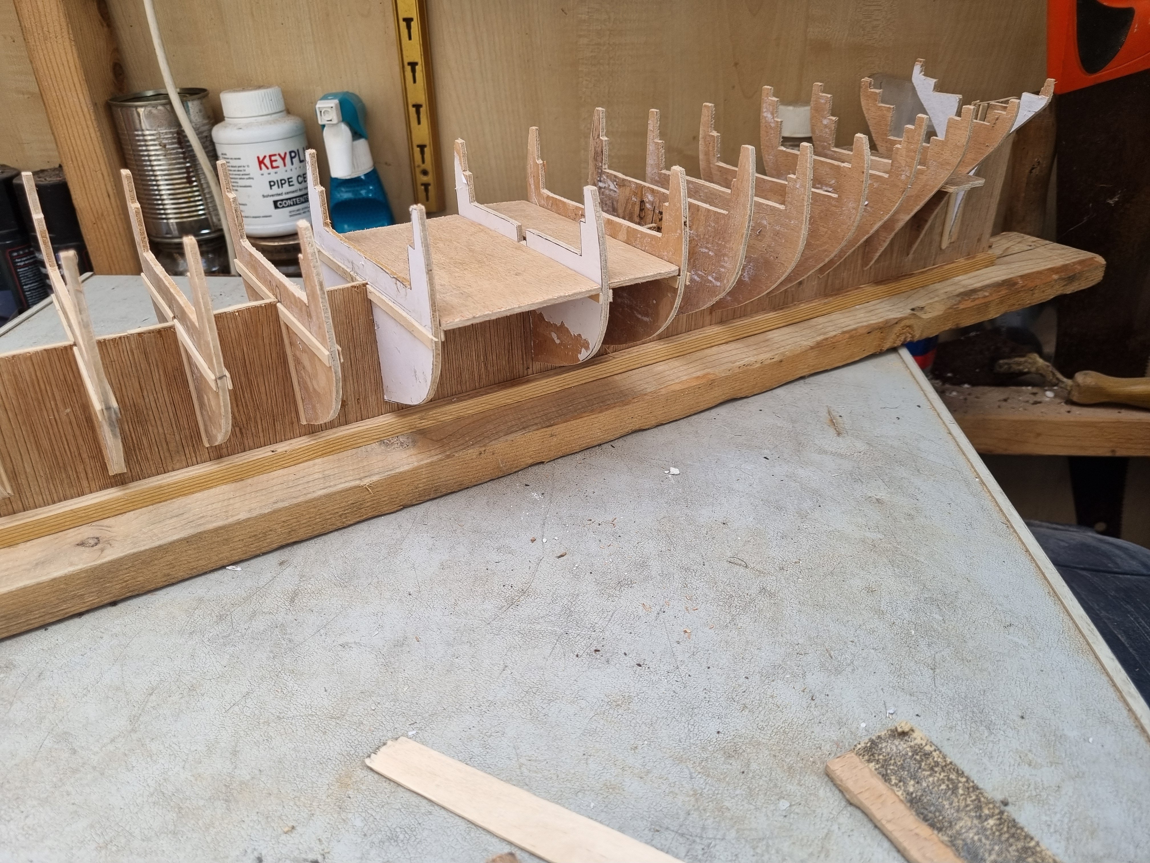
Been a busy day today and haven't found too much time for the boat this weekend.

So this is the aft end the dummy deck is locked in and the support cross beams for the main deck are temporary clamped in place.

The cross beams are lined up and glued in place. I have drilled through the false deck to the bracing below for the Foremast and the Mizzen. The central supports for 14, 15 and 16 are in place. I will add additional bracing for and aft of the mast. This mast will go through the aft deck and deckhouse. As long as I am careful to be accurate, this mast should finish vertical with a rake aft of 84 degrees.

A different angle view, judging by the list to Starboard of the mizzen mast, there is a little adjustment to do.
Simon
- Baker, GrandpaPhil, Rick310 and 2 others
-
5
-
On 5/3/2024 at 9:26 AM, Baker said:
I just went through your build log. Nice work.
I also have a cat. And an partially build Thermopylae kit from Sergal. Someone started it, gave up, and that's how it ended up with me
The idea is to start building next winter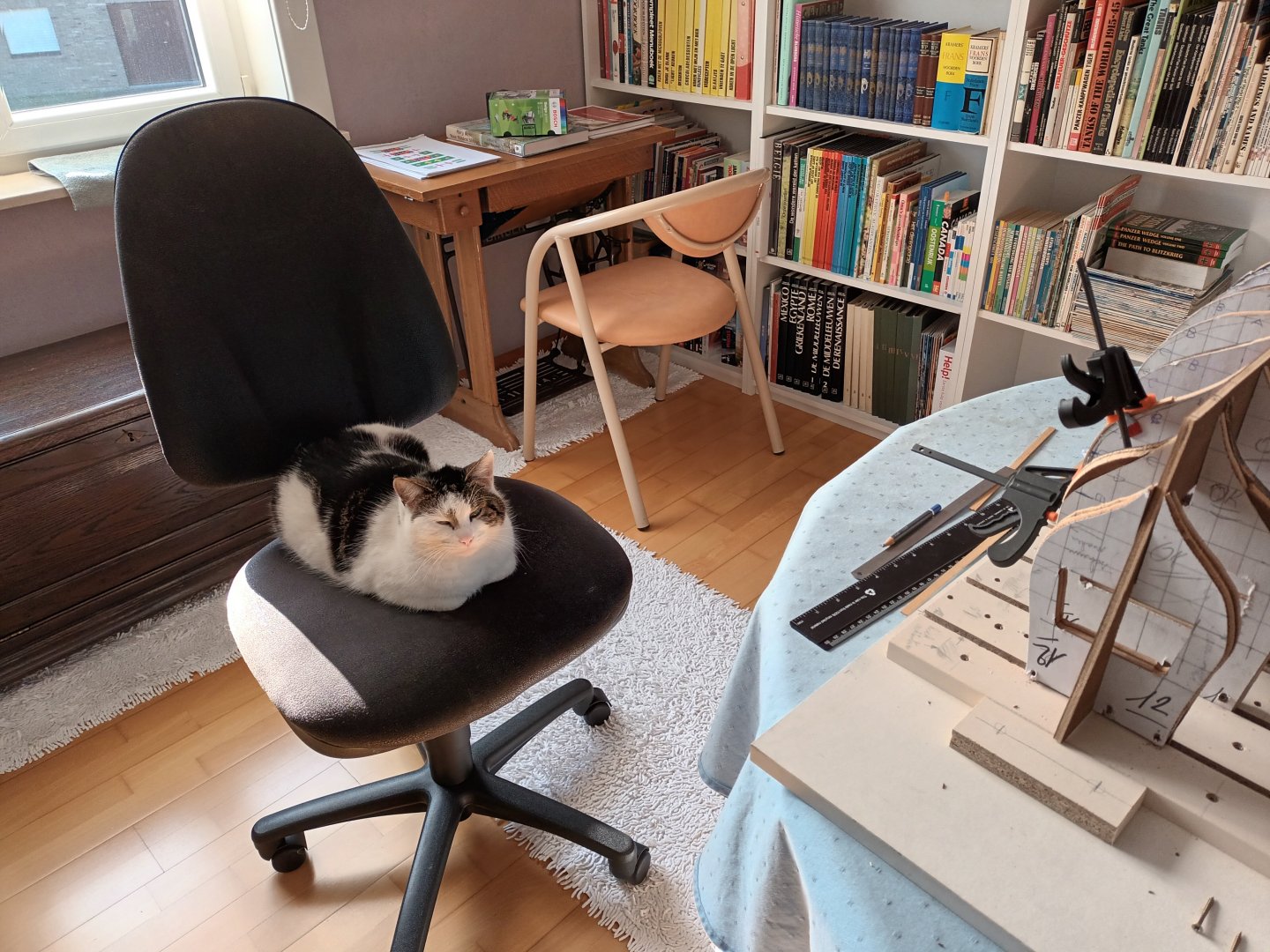
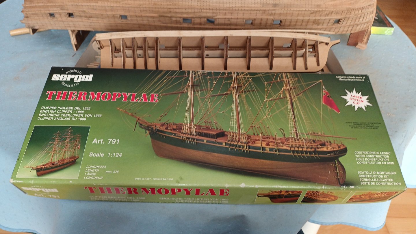
I did think of looking for a second hand kit but I don't intend to spend too much on this boat, hence my use of materials that I get for free.
I did have to pay £9 for the sheet of ply and I spent £10 on some Bass wood today but that's it so far.
I do have some set aside for decent strip wood from Cornwall model boats but at 27p to the dearer woods at 37p per strip it should not cost more than another £12 to plank the hull.
I hope you create a log for your build, I will tag along when you do.
Simon
-
Just a bit clearer without all the clamps.
- Keith Black, Scottish Guy, davyboy and 2 others
-
5
-
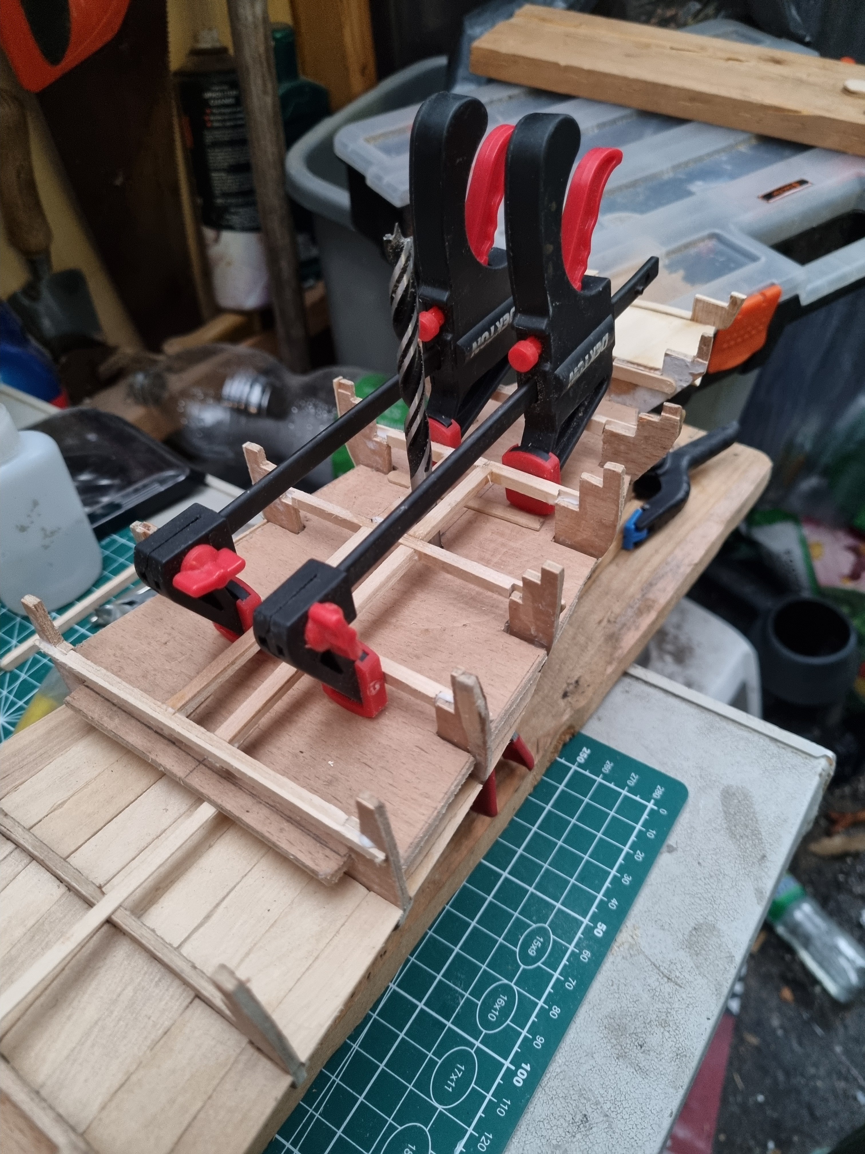
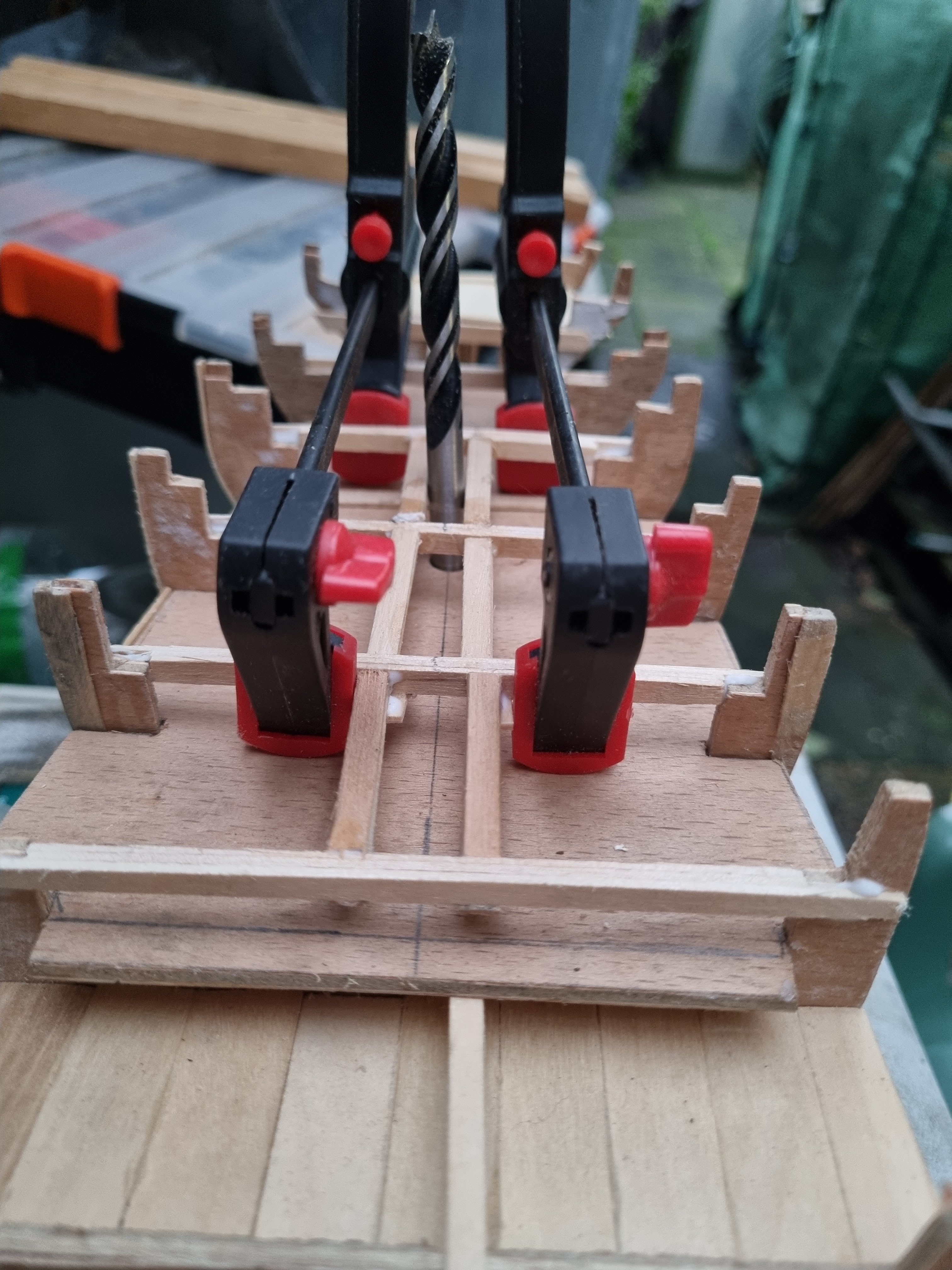
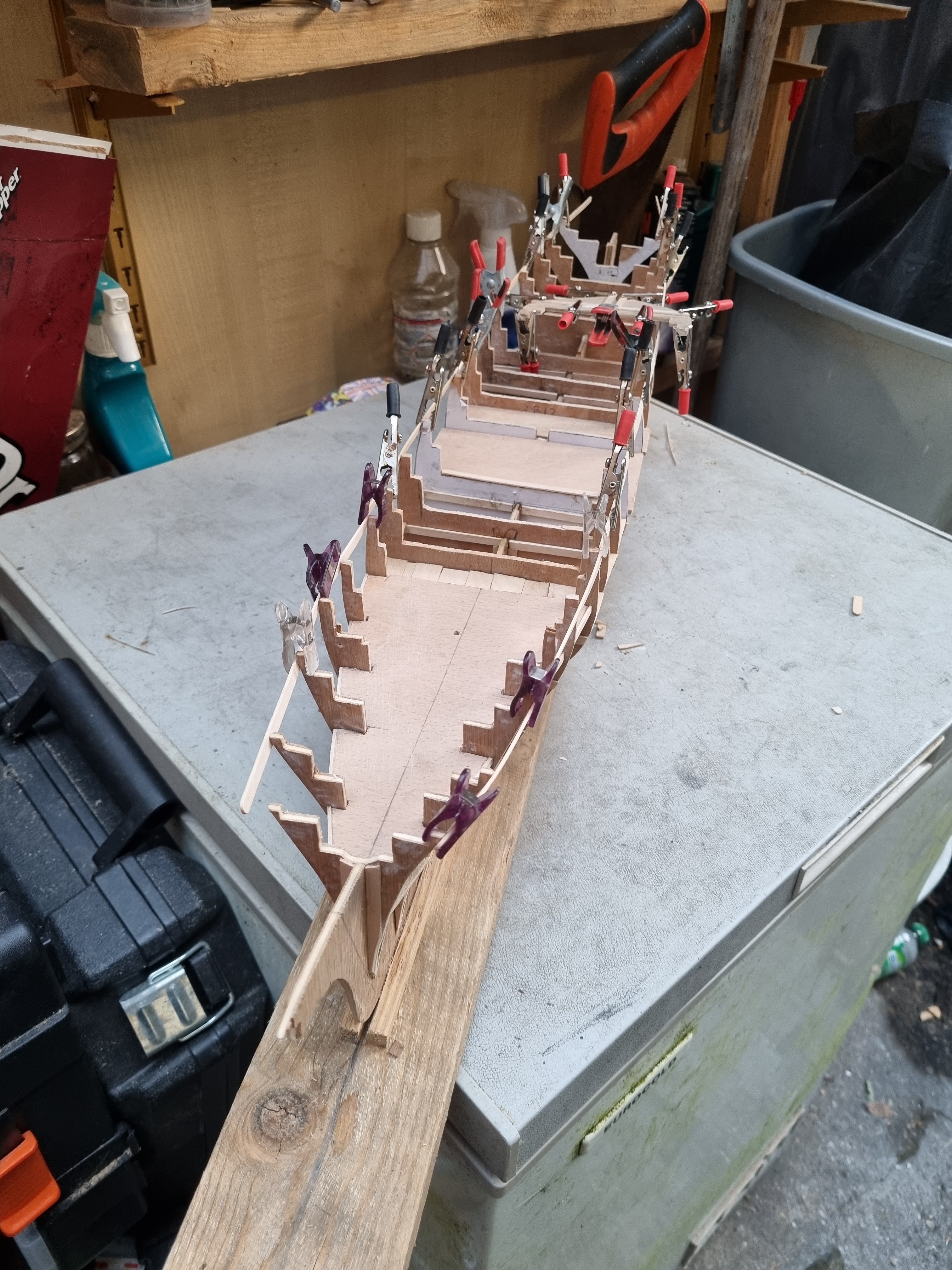
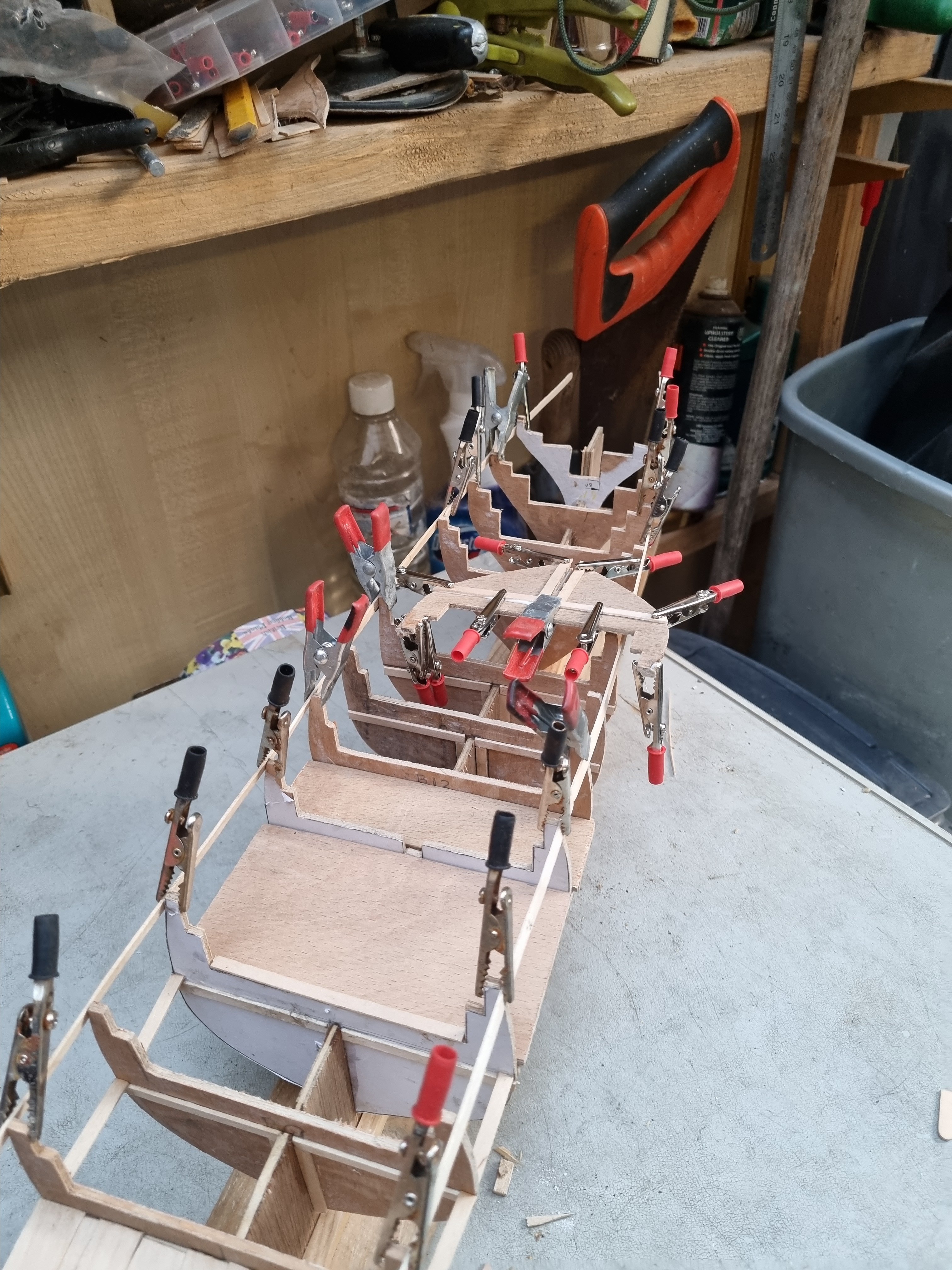
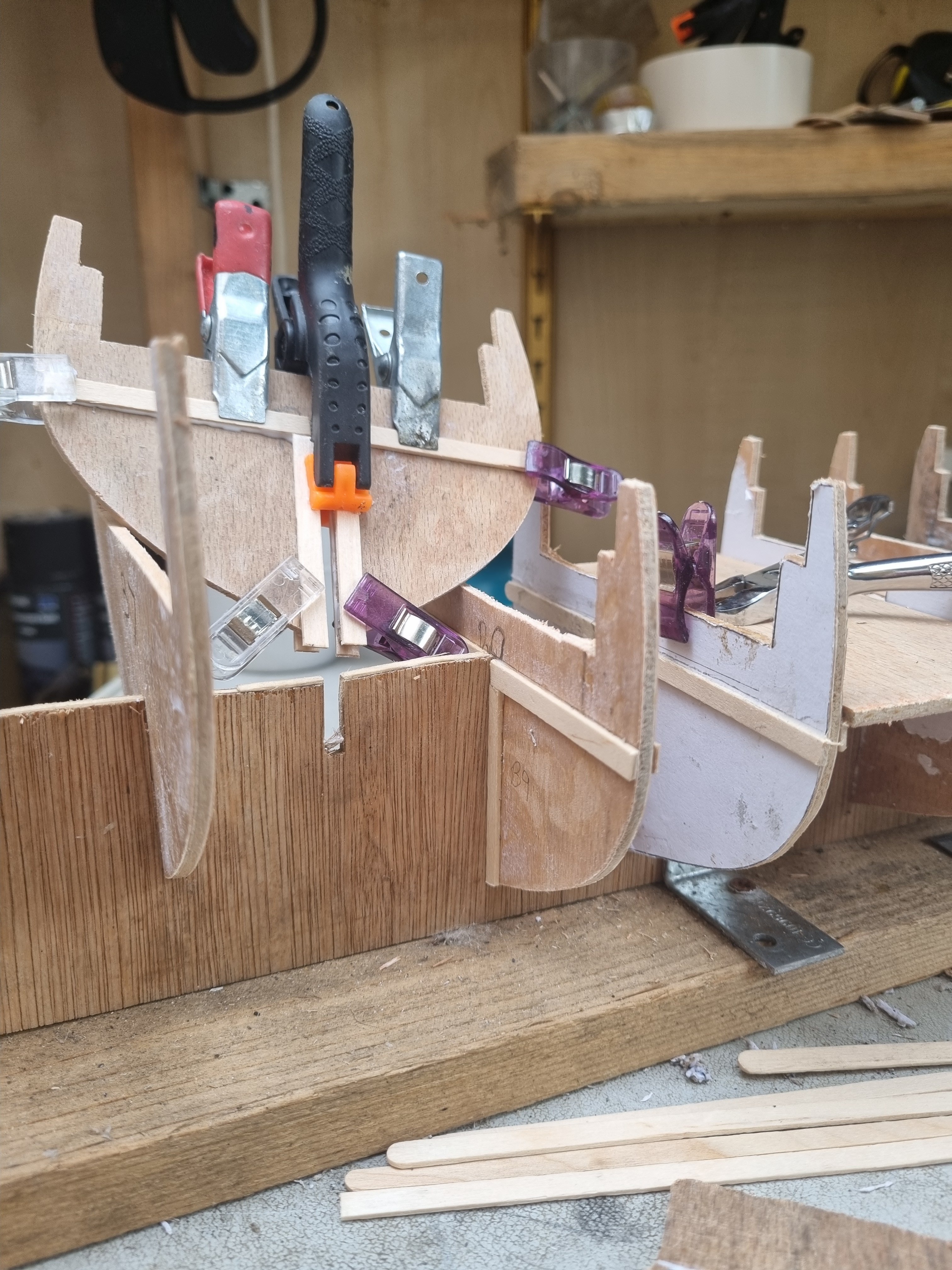
Jumping from task to task again but I can't fix no 18 - 20 till I know where the deck will be. So I have created beams a cross 14 to 18 so far so I can line up the camber of the main deck. These are clamped up because I have laminated coffee stirrers to create these beams and they are only dry fitted and clamped into place. You can't have too many clamps.
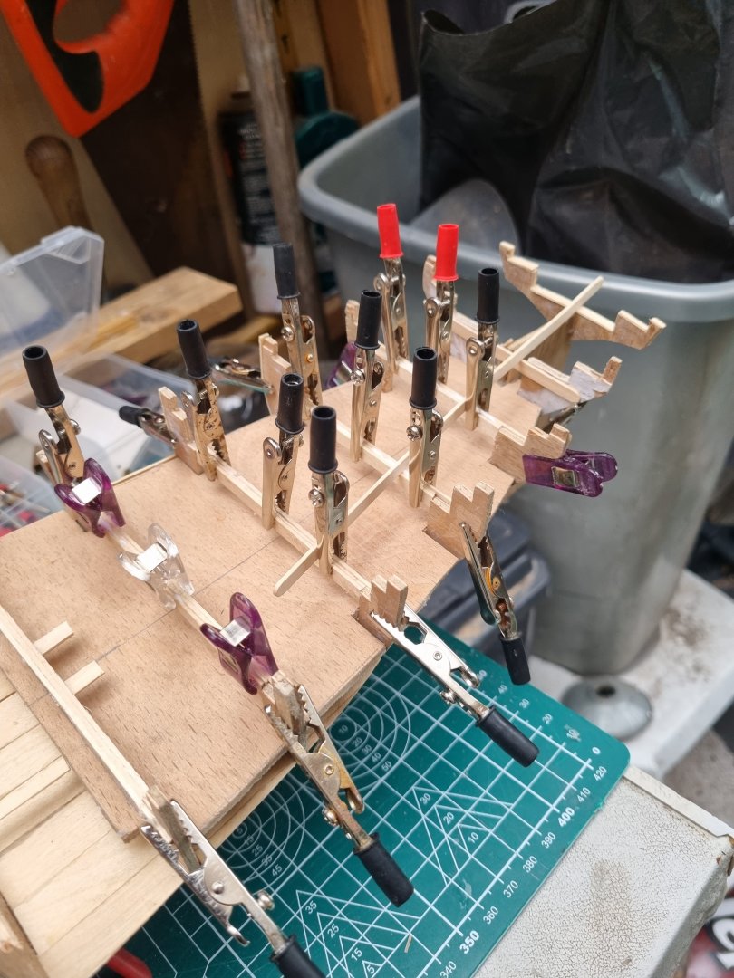
There will be supports fore and aft. If I was Chuck, there would be half lap joints on every junction but I am going to cheat, there will be tabs glued to the underside of the junction so I can glue the fore/aft pieces without awkward clamping tasks.
- Scottish Guy, davyboy, GrandpaPhil and 2 others
-
5
-
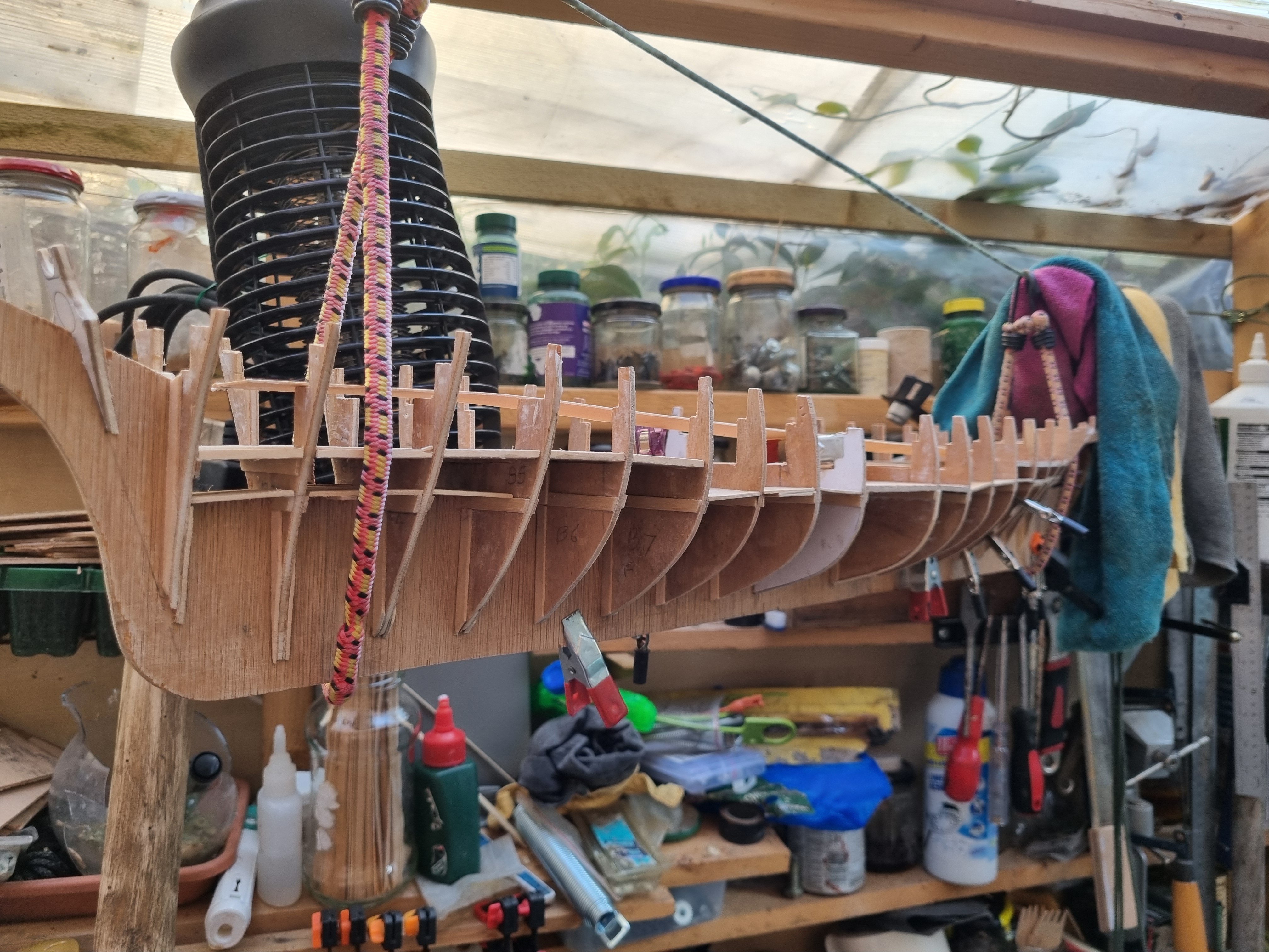
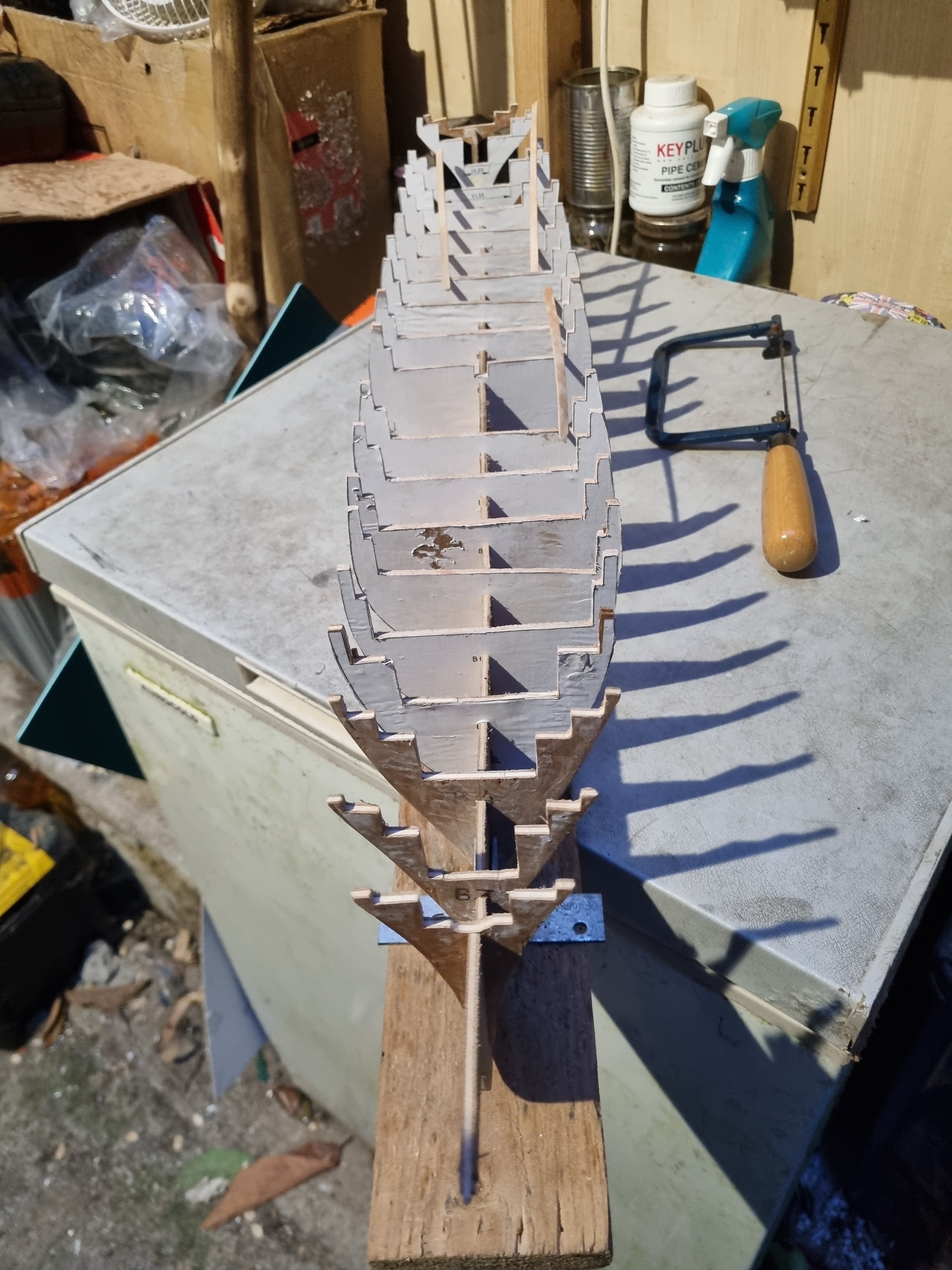
Had some time today and started checking the profiles with a length of 1mm x 5mm beech. Mostly just a case of removing excess or putting on strips where cut to fine.

Starboard mostly done but port side still to do. Bulkhead 18, 19 and 20 might be a bit of a challenge.
- Baker, GrandpaPhil, berhard and 3 others
-
6
-
-
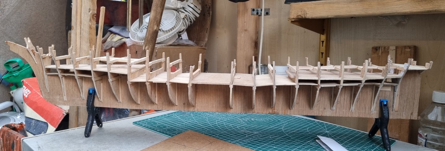
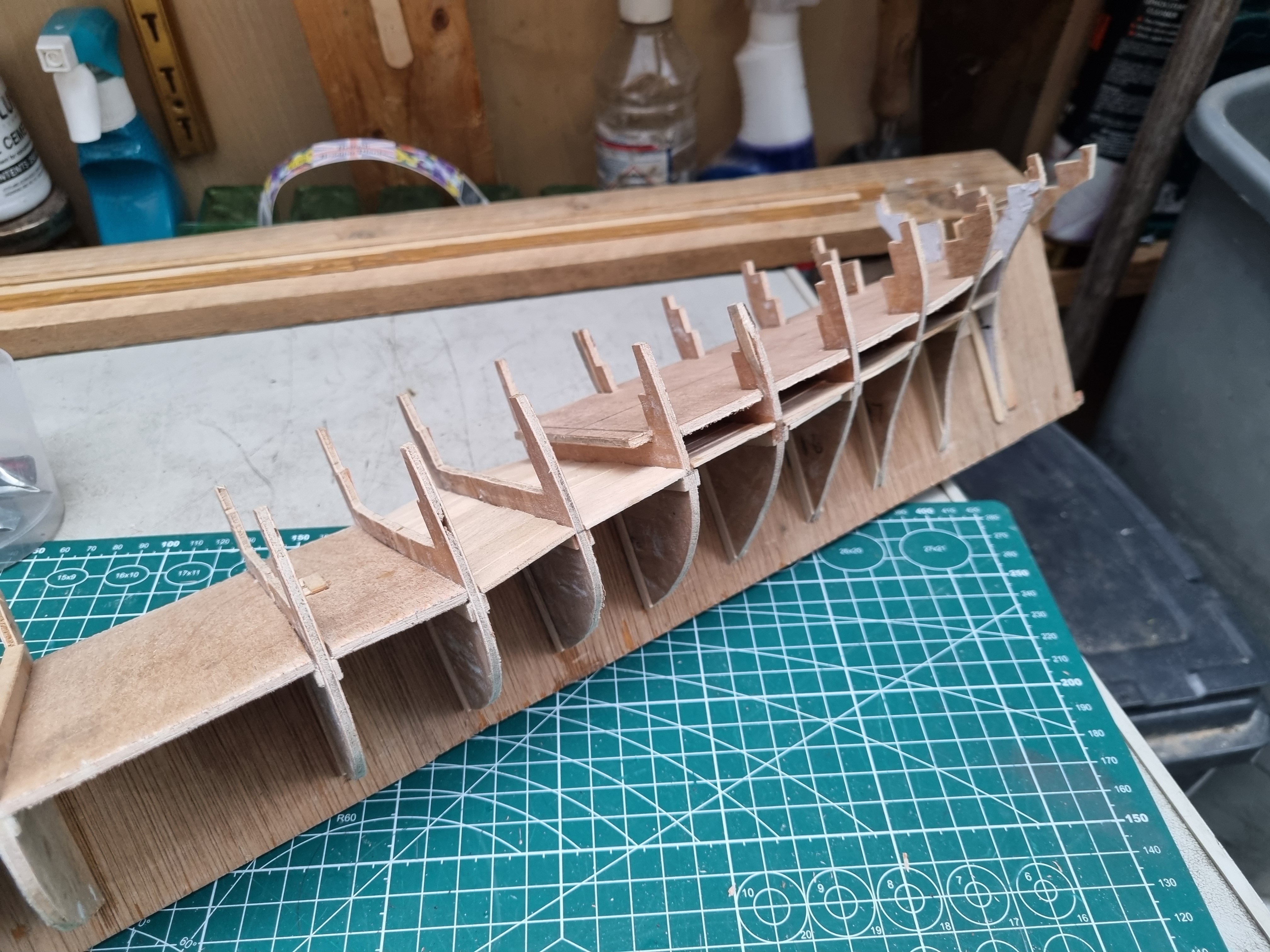
Just a couple of images of progress made this week

These are mid-decks, as I already used ply in the centre section, I am not sure that adding another layer of ply is actually necessary, the structure is already stable.
I will concentrate on the stern for the time being as that currently has no horizontal frame to lock it in place.
- Javelin, Scottish Guy, Keith Black and 1 other
-
4
-
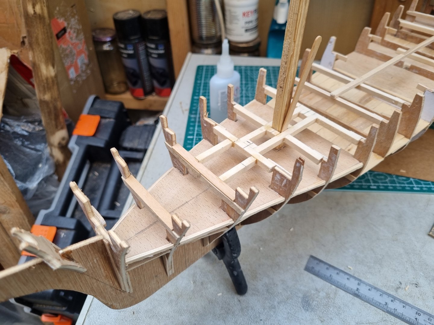
So I have set up the knighthead and have glued all the bracing in place. Not my best work but it is now straight and stable.
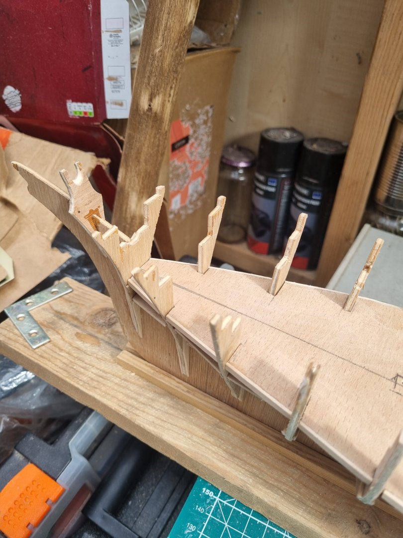

So I now have to trim everything flush with the bulkheads. Time to check all the plank runs to find where I need to fine tune the shape.
Also, I can get all the measurements of the below deck, main, for castle and aft decks.
- davyboy, Scottish Guy, GrandpaPhil and 1 other
-
4
-
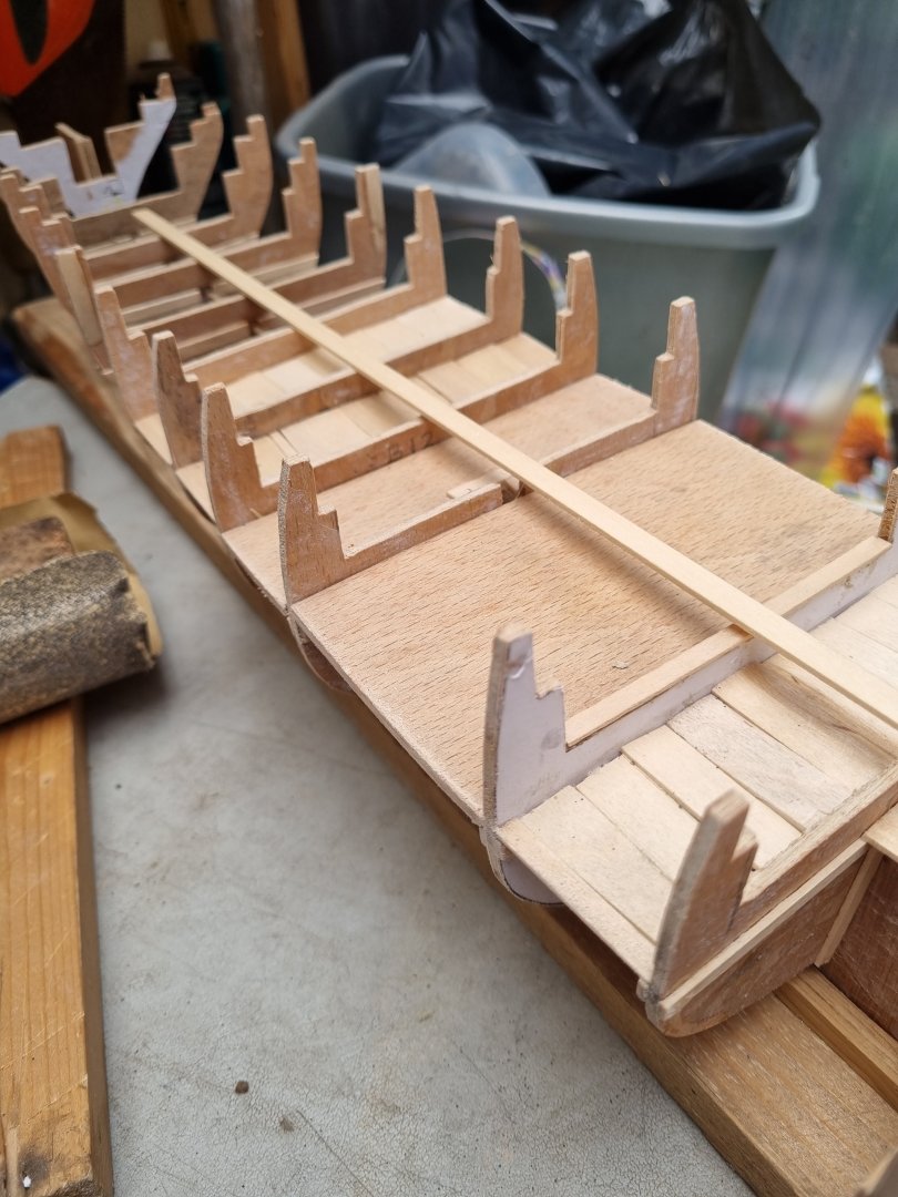
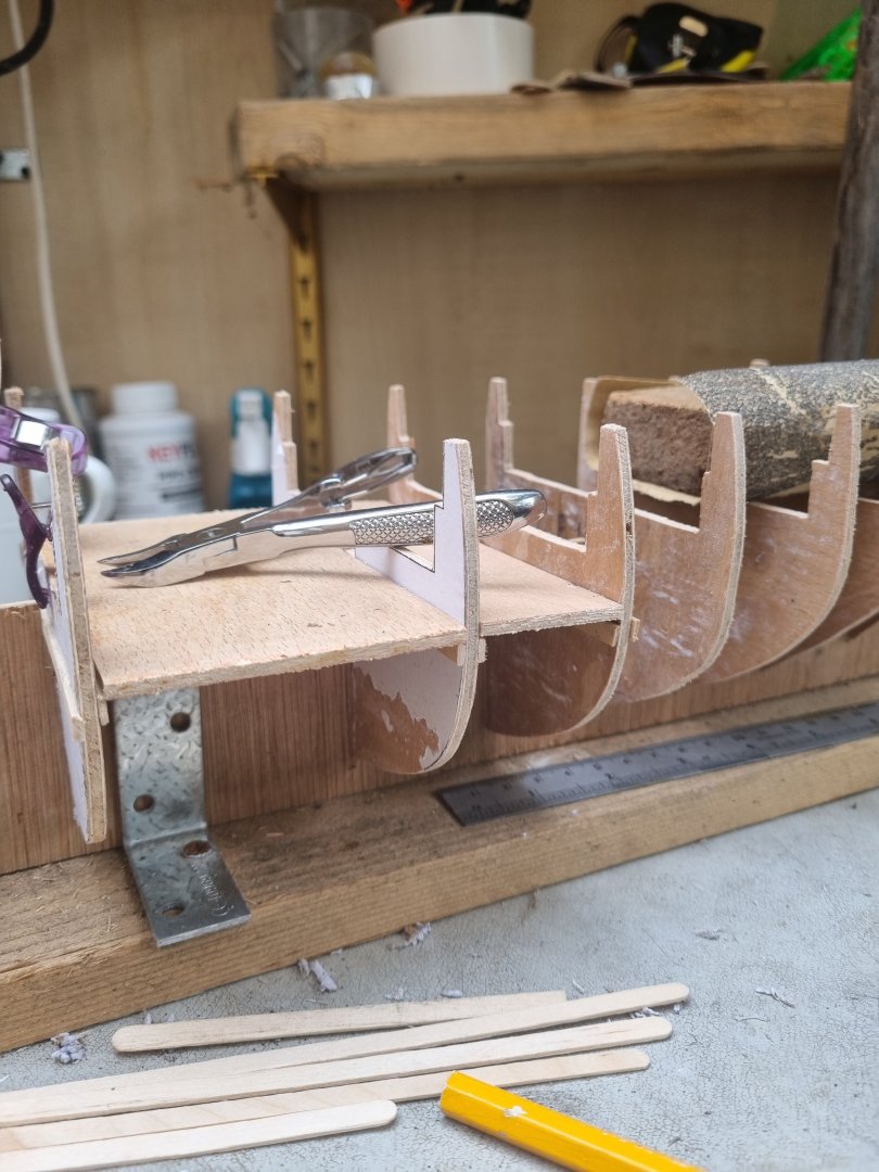
Continuing to build in the spacers between the bulkheads. It takes time to cut and shape the material I am using.
What it looks like is immaterial as they will never see the light of day once the decks are installed.
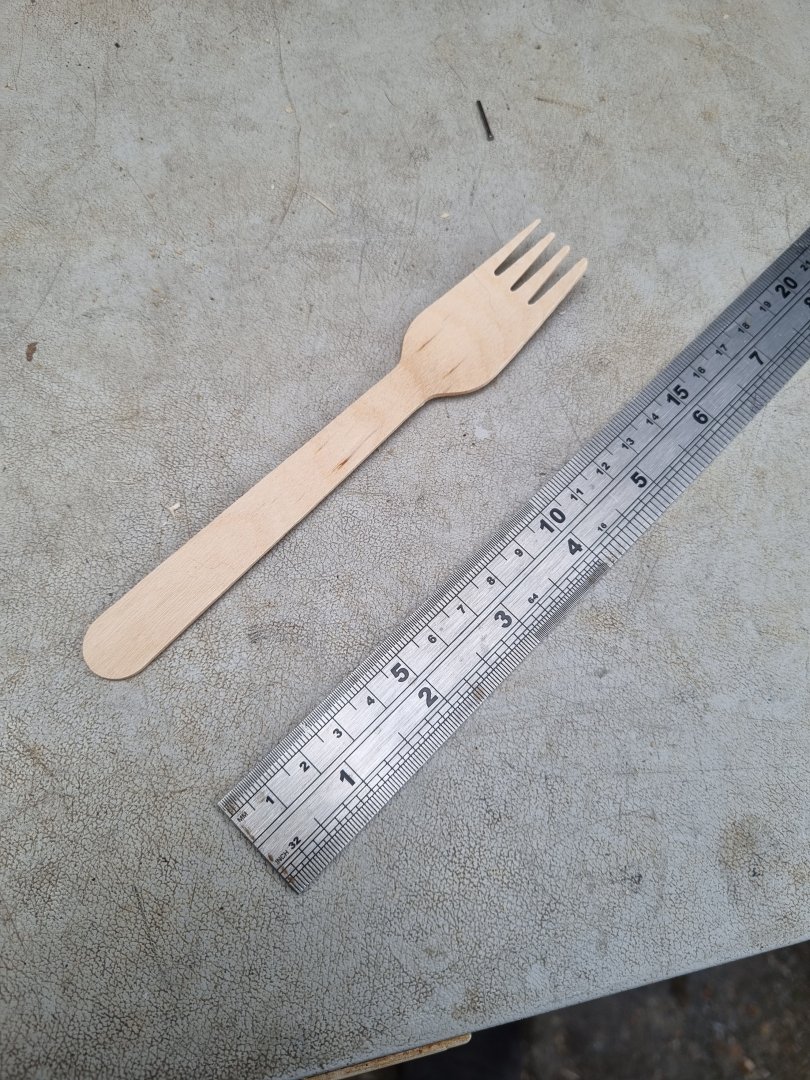
KFC have kindly changed from plastic sports to wooden spoons and forks and this has provided a cost effective source for this purpose.
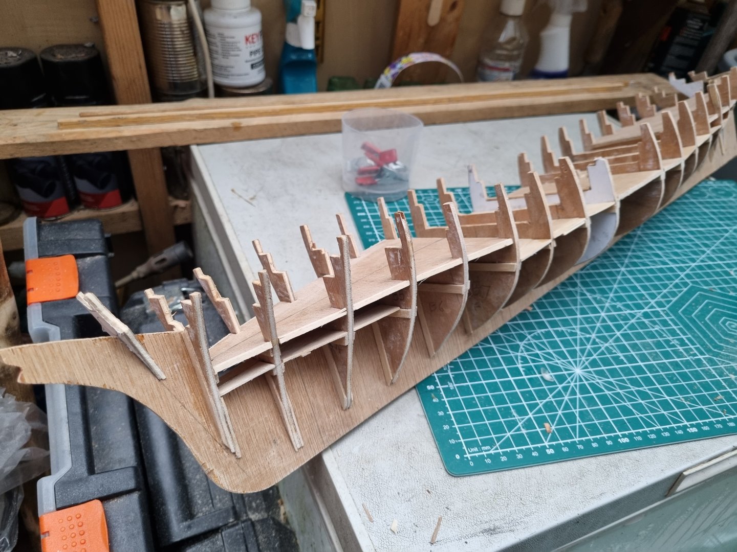
As I go, I am checking for straight lines and the fore section is now very stable and nearly complete.
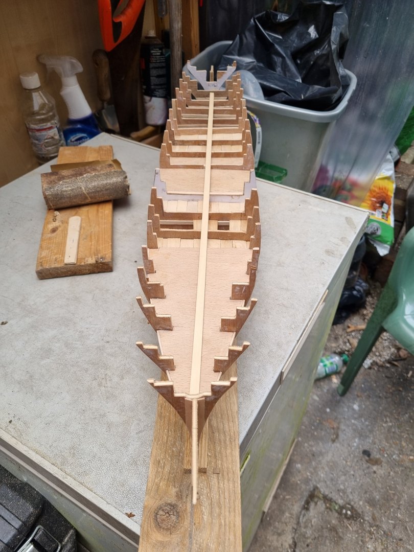 Just the sections aft of bulkhead 14 to complete.
Simon
- davyboy, Keith Black, berhard and 3 others
-
6
-
So progress is slow as each bulkhead has to have the stringers attached to add support for the spacers to be inserted.
While I do this, I created the forward section of the false deck but for some reason I haven't been able to accurately set the width. Correcting this by adding extra wood around the edges. Still a little more to do there.

I tried out a set of strips to check the run and this identified a few errors in drawing and cutting out of the bulkheads. All fixable so no real problem and all the errors will be below the decks and will not see the light of day once the hull is planked.
One thing, in this hobby, when someone asked what tools they need, tell them to buy lots of clamps. And when they think they have enough, go and buy some more, you can never have too many clamps.

Simon
-
So I made an adjustment to the way the keelson is secured to the board, this should keep it straight. The three brackets this replaces were not holding the keelson very securely.


I can't believe the price of balsa, it's ridiculous. So I will only block the stem and stern, and use accurately cut spacers to maintain the correct position and spacing of the bulkheads. I have been adding additional strips to the bulkheads, these help to keep the bulkhead square to the keelson and something to glue the spacers to.
Just have to work out the correct position for the knighthead then can work on the stem blocking shape.
Simon
-
The ply I used for the bulkheads is fine but but the keelson flexs like an agitated snake. I have looked into the price of balsa block and I just can't believe the price of it.
So, with my thinking cap on I have decided to create a series of boxes with the upper level being in no more than three pieces. This means an extra level of ply level with the top of the keelson. To support this I am adding strengthener to each bulkhead. They will also increase the thickness of each bulkhead to help keep them at 90 degrees to the keelson.


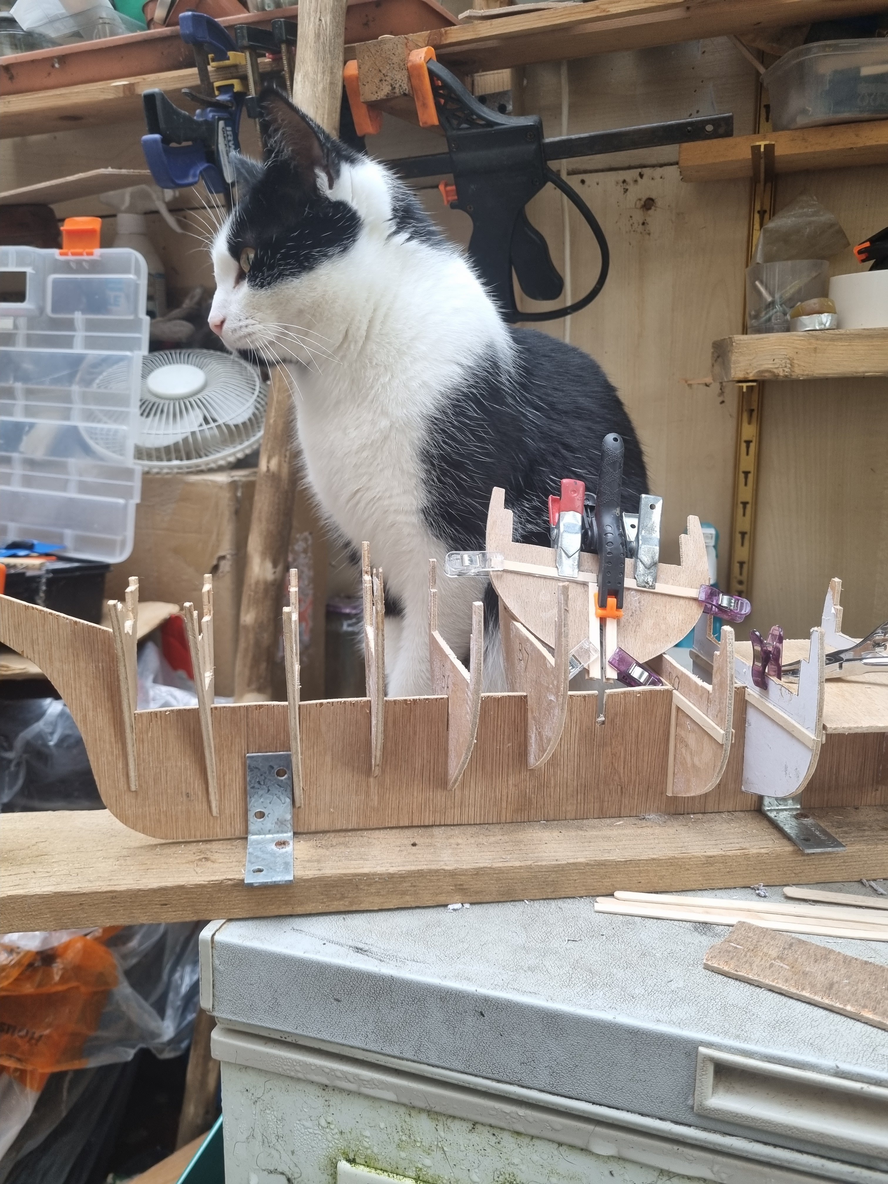
And as you can see, my assistant is ready to lend a paw.
Simon
-
-
I will strip of the paper templates and I need to locate the places on the keelson for sockets for the masts. I am debating which is better, filing the space between each bulkhead with balsa or can I just add squares of ply. Stem and Stern will have to be balso filled so I have something to support the planking.
I intend to add a lower deck the lengh of the boat which should add rigidity and then there will be the main deck which should add strength.
The first planking will be 1/32" basswood and I will have a look at Cornwall Model Boats for the top planking. But that is a long way off just yet.
- mtaylor, Scottish Guy and Keith Black
-
3
-
Thanks Keith, well it might be raining but my workshop is dry, well mostly.

But at least I managed to cut out the main bulkheads.


The penaltimate one, no 19, is sitting proud but I can adjust that when I get my next spare time.
These were all cut by hand as that scrollsaw I bought can't cope with 3.6mm ply.
Still not advanced my rigging on Cutty as my 4 legged fiends are too interested in what I do.
- GrandpaPhil, mtaylor, Mirabell61 and 4 others
-
7
-
Its been a long time since I last posted but I have bit the bullet and have adjusted or cut out the majority of the bulkheads, bar three. So far they appear to be lining up as planned, pictures will follow. The main delay has been the fact that my workshop is no longer my armchair, it is outside and only partially enclosed, so had to wait for warmer weather.
- Scottish Guy, mtaylor and Keith Black
-
3
-
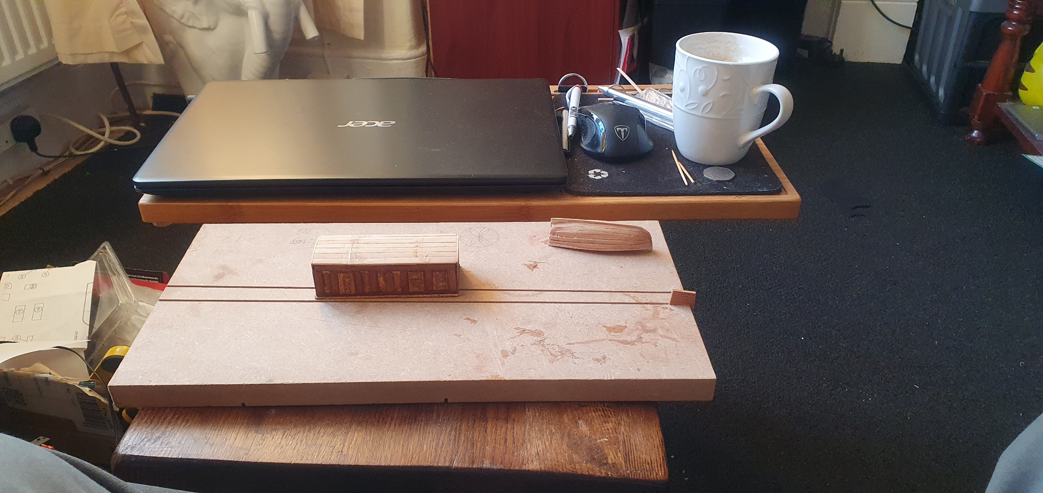
-
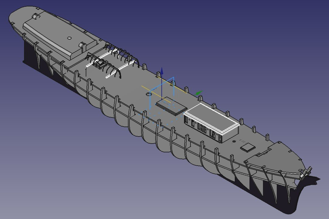
I used a generic imge of Line drawings for a Captains Gig and constructed virtual model. I used the templates derived from yjese plans and the resultant phisical model has been installed on Cutty Sark.
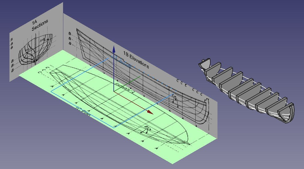
I faithfully created the frames from section 1A . I took a template from Elevayions 1B to give me the shape of the keel and the curvature of yje Gunwhales. However, creating the Plan from 1C shows an anomile whick can be clearly seen on the model as the lines should intersect the edges of the sections. This is relatively accurate on the stern half of the boat but not so forward of the central section. If i tried this with the vertical profiles from 1B Elevations, you would get a similar result.
The drwings are cut and pasted from a single drawing. I have combined the documents to ensure that A, B and C are in the same proportion in each image but the result is always the same. I am happy with the boat built based on these drawings and have saved the formers so I can build a similar boat for Big T but this part of CAD work is a little frustrating.
Also, I think I am reaching the limit of the complexity that either FreeCAD or my Laptop can work with.
When creating complex documents there are noticable delays between mouse clicks and action on the screen plus when I try to keep my files in a structured way, half the screen blacks out when I am moving files.
I needed to edit the Main Deck file as I am not happy that this does not extend out to the side of the vessel, but I cant edit the sketch. Nor will FreeCAD let me delete it and star again without affecting many other parts. I have hidden this document and am nearly finished creating a new one but this just exagerates the problems with a slow system.
My laptop is not that old but I suspect that the built in graphics card is reaching the limits of its capabilities.
Bah humbug.
Simon
- Keith Black, mtaylor, GrandpaPhil and 1 other
-
4


Thermopylae by My Fathers Son - or as near as I can get it
in - Build logs for subjects built 1851 - 1900
Posted
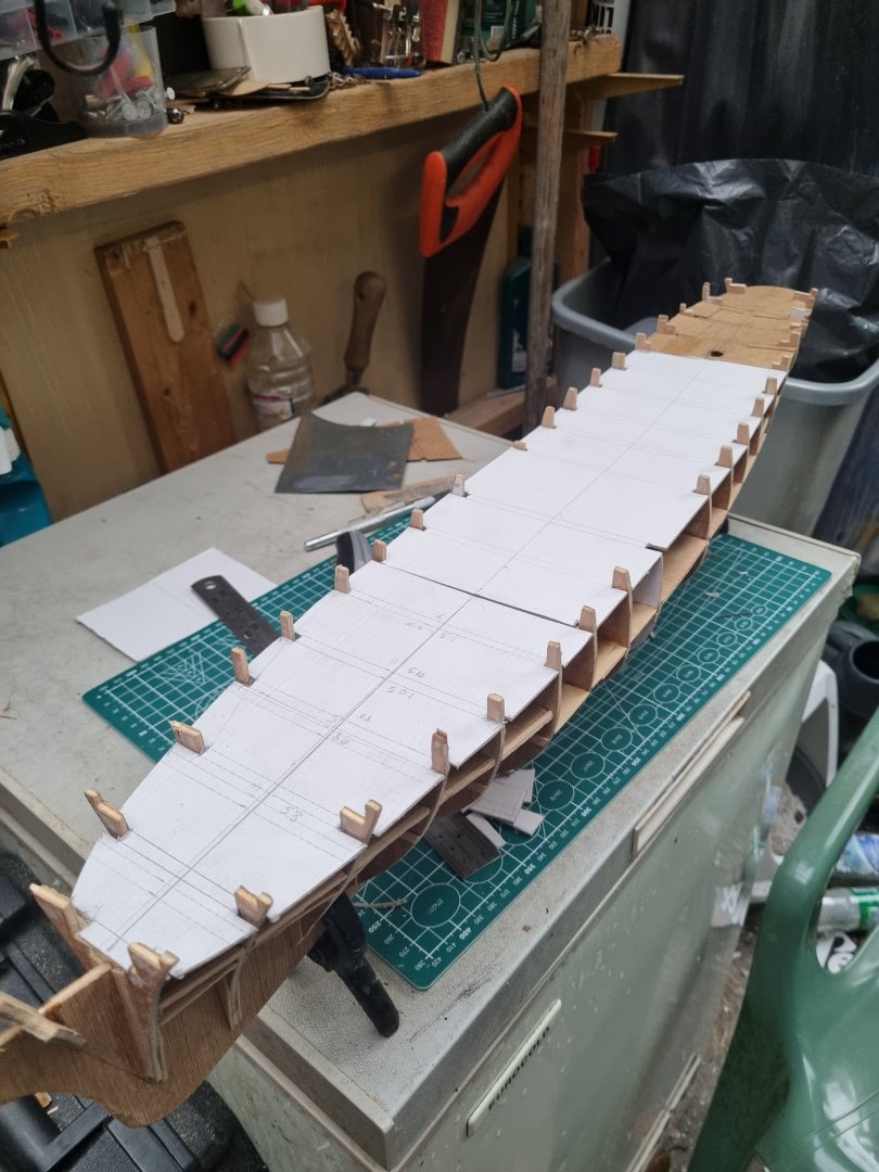
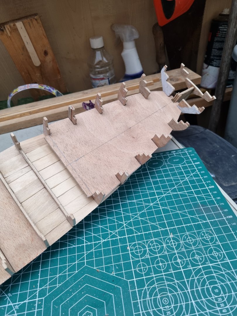
The broken tabs are not proving to be a problem, as you can see, I have managed to create templates for the main, fore and aft decks. I have erred on the side of caution and they are all slightly over sized so I can sand the actual decks once they are cut out. The main deck was made in three parts and after getting them lined up, I have glued strips over the joins. This is shoebox card so it's quite sturdy.
Frustratingly, she is not symmetrical, some of which can be rectified by building up or filing down excess but there will be a case of "so be it". I will know it but I doubt any casual observer will.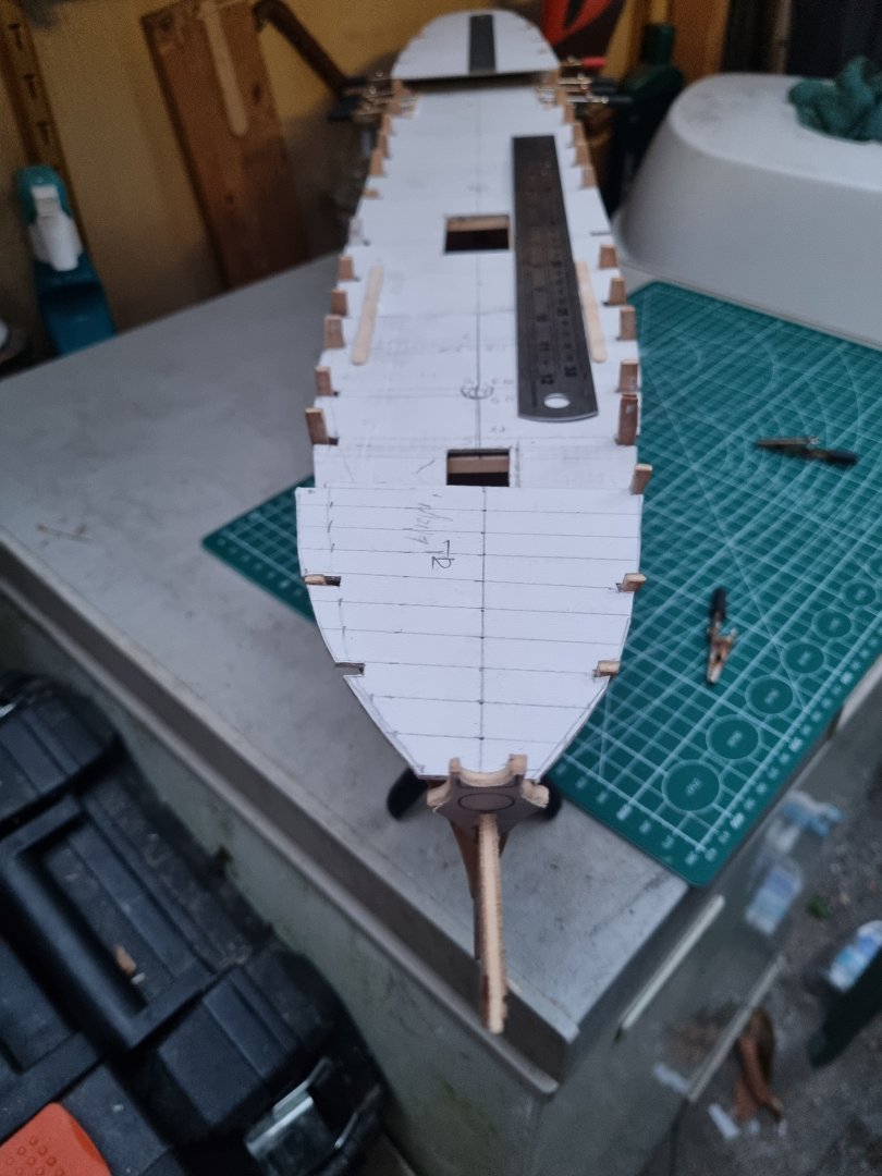
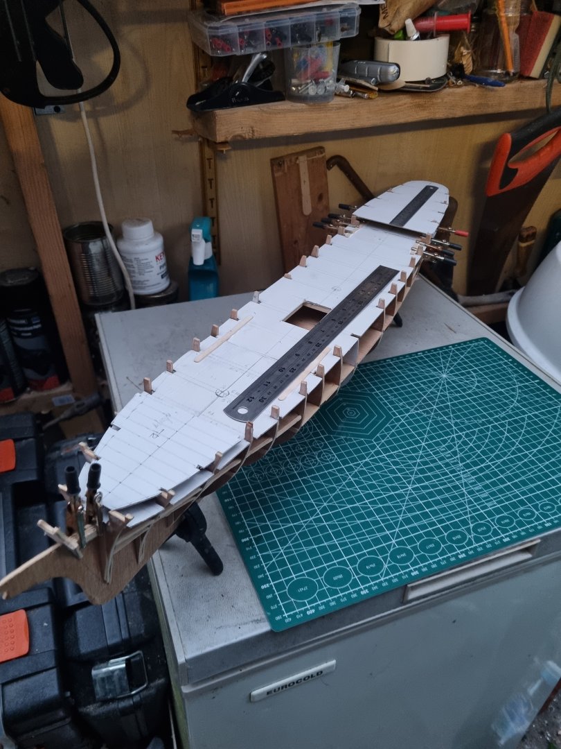
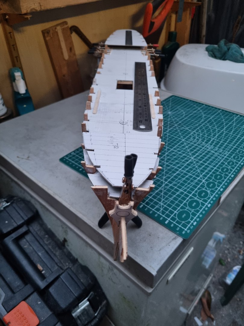

One of those annoying things is the bow, the ply has warped, I am taking steps to correct this but there may still be a slight twist to port in the end. I suspect once the decks are fixed in place and the hull planed, most of this will be sorted.
Simon