Dan Vadas
-
Posts
3,261 -
Joined
-
Last visited
Content Type
Profiles
Forums
Gallery
Events
Everything posted by Dan Vadas
-
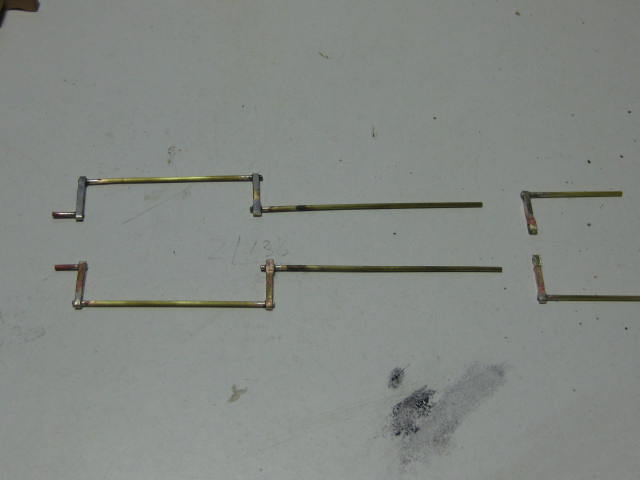
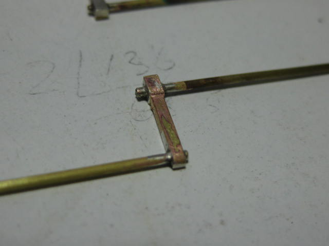
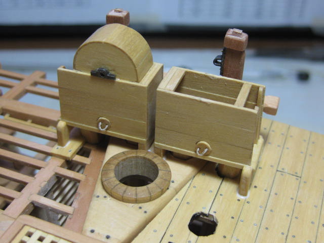
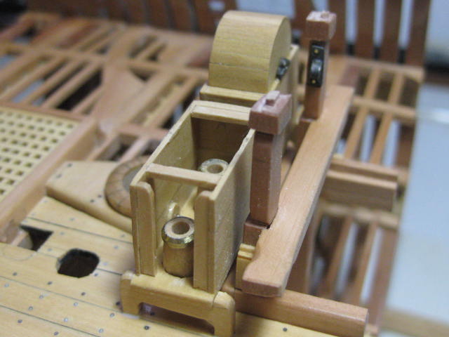
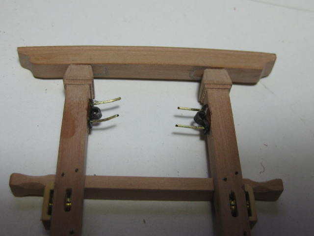
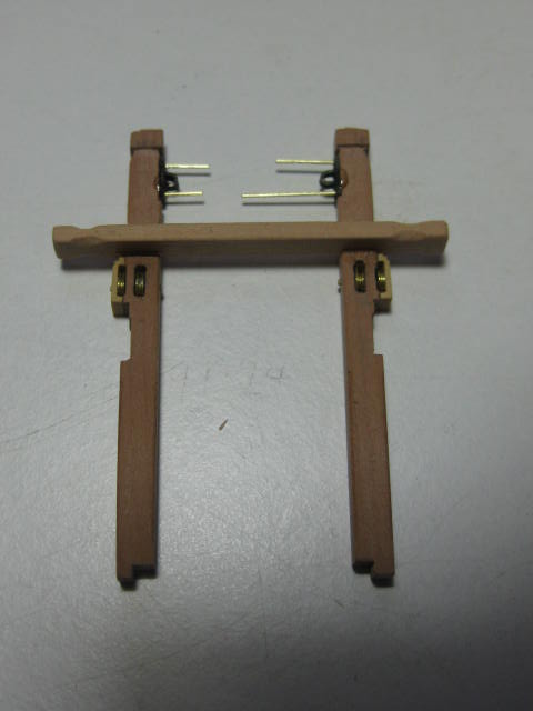
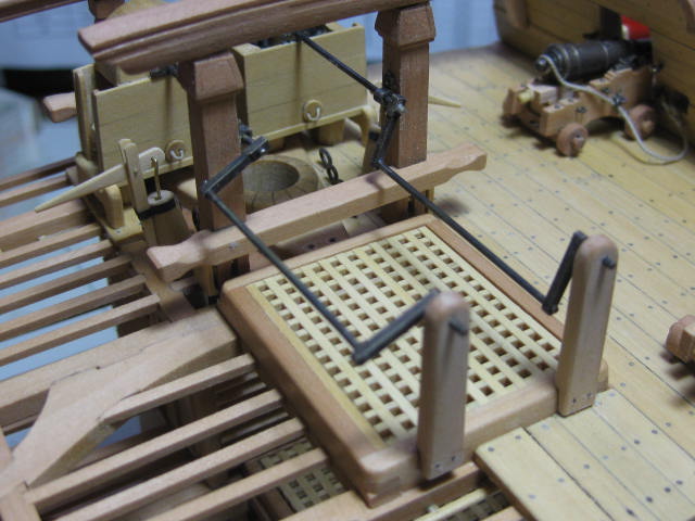
Hi all, I've had some Internet issues lately, and haven't been able to post much of anything. It's all resolved now though, so I have a lot of catch-up to do. Where to start ? I'd previously made the Main Topsail Sheet Bitts and the Main Jeer Bitts, so these could now be fitted along with the Eyebolts around the main mast and those for the Gun Tackles in the spirketting. Next job was to make the Chain Pump mechanisms, starting with the Cranks. These were all silver soldered and blackened. I left the joints in the aft ends of the cranks to be epoxied in after the rest was assembled : Next I made and fitted the Cisterns. A more detailed description of how these were assembled can be found in my Log of the full Vulture model : The Rhodings for both bitts came next. I filed these from brass sheet. The "bolts" were easier to fit in longer lengths, which were later cut down and blackened after the epoxy had dried : The pumps completed. You will notice that the pics are a bit out of sequence - I hadn't taken many pictures during construction and had to go back and take them after I'd fitted a few other things : Continued in next post .......


- 268 replies
-
- 19
-

-
Opinions on Sherline DRO for Lathe
Dan Vadas replied to rtropp's topic in Modeling tools and Workshop Equipment
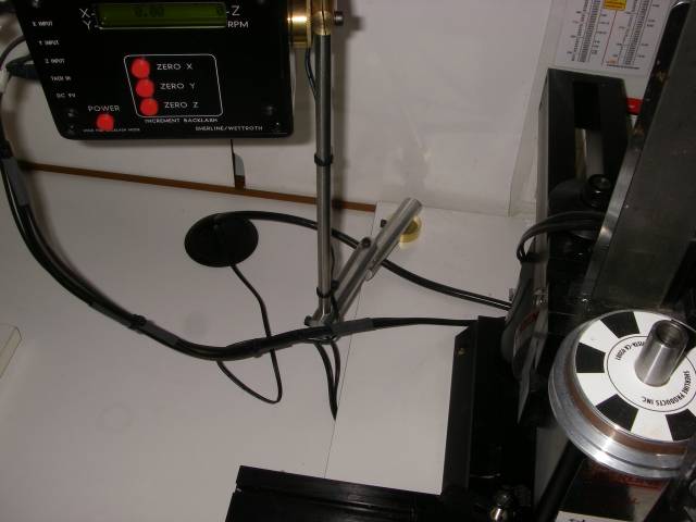
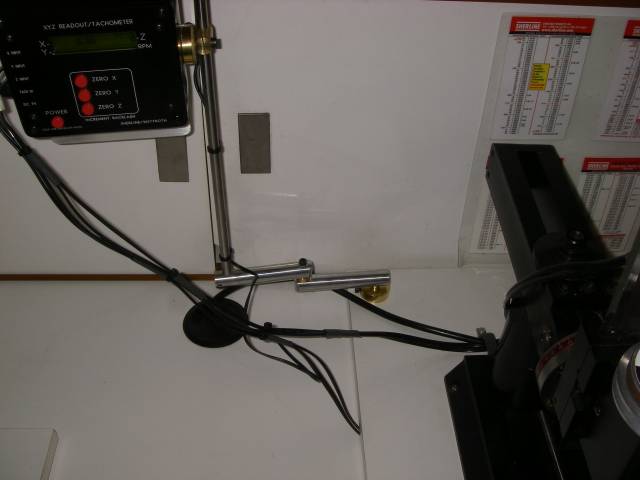
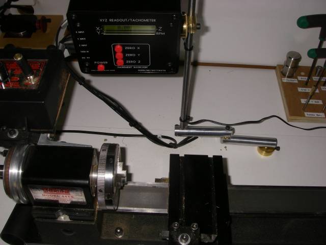
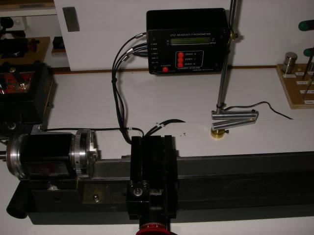
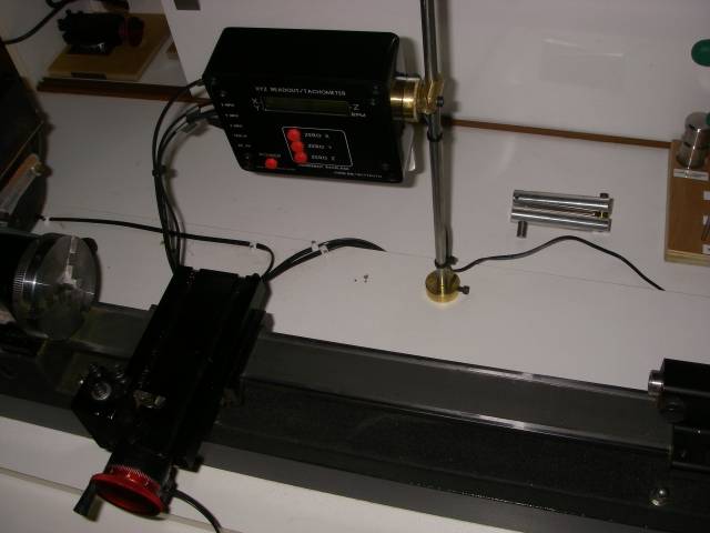
I use the DRO on both my Sherline lathe and mill and wouldn't be without them. They make life a LOT easier. Here are some pics of a stand that I made for mine. I have a base screwed to each baseboard, so it's only a matter of unplugging the leads and loosening one screw to go from one machine to the other. It takes about 40 seconds to change from the lathe to the mill. Danny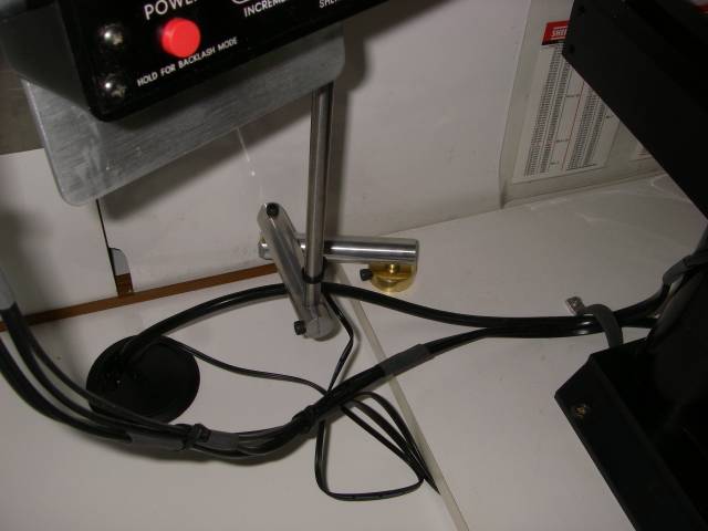
- 30 replies
-
- 12
-
-
Lovely work Druxey. and I can't believe how quickly you finished it (her?). :cheers) Danny
- 641 replies
-
- 3
-
-
- greenwich hospital
- barge
- (and 1 more)
-
Richard it was generally used on English warships of the 18th and early 19th century. Further than that I don't know. Danny
-
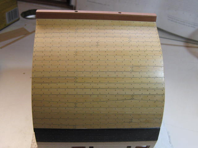
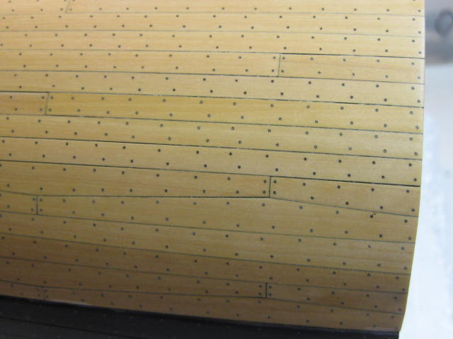
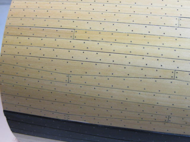
Thank you all once again for the comments and Likes . Richard, the planking "pattern" is called Top and Butt. It's used in areas of high stress such as the Wales and the 6 planks below them, and also on the Gun Deck where the guns are placed. Danny
-
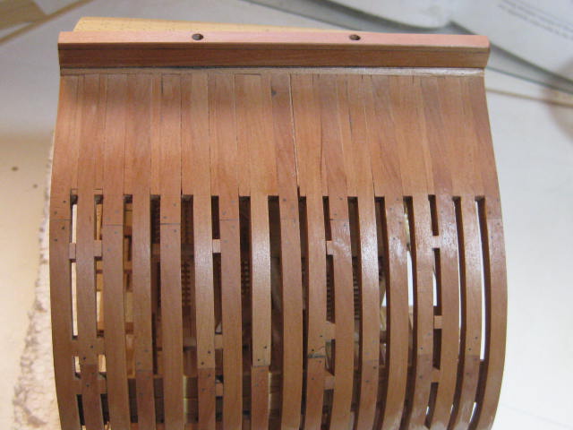
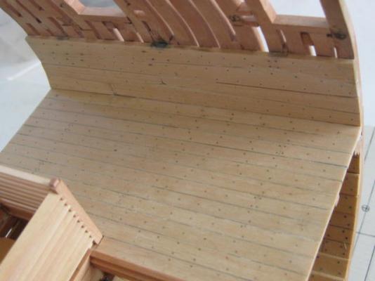
Thank you Pat, Anthony, Greg and Greg . Natural circulation as hotter air rises I guess Greg. Hi all, It seems like an age since I last updated the log, but I've been busy with the tedious (but fun) work of planking and treenailing the hull : I've clear coated the hull inside and out to the level of the wales. Further work on Drift Rails etc will be done before I go higher : I also fitted the afore-mentioned Port Liners : Danny
- 268 replies
-
- 37
-
-
We're going on a Harbour Cruise on Friday John, and will probably take a quick look into the Museum the same day. Have to go home the same day. Danny
- 745 replies
-
- 4
-
-
- francis pritt
- mission ship
- (and 1 more)
-
Great work as always John . I hope to see her next weekend when I pay a visit to the Museum. Danny
- 745 replies
-
- 3
-
-
- francis pritt
- mission ship
- (and 1 more)
-
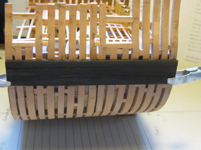
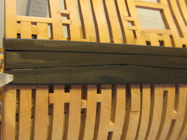
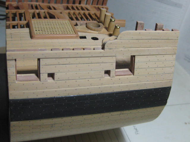
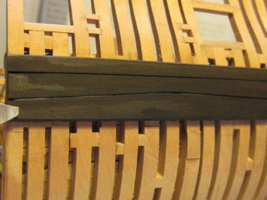
Thank you all for the comments and Likes . I've moved to the External Planking of the Port side, as one of the next steps on the inside is fitting the Port Liners which need to be done after the external planking goes on. First up is the Wales, which are 4 1/2" thick (real size). The upper strake is parallel while the two lower strakes are in "Top and Butt" configuration. I've made them from Ebony. The smudges on the wales are from water, as I'd just fitted them and cleaned off the excess glue. I've sanded a very slight bevel on the edges to make them stand out a bit better. The top and bottom strakes have a significant bevel where they meet up with the thinner strakes above and below : Danny

- 268 replies
-
- 28
-
-
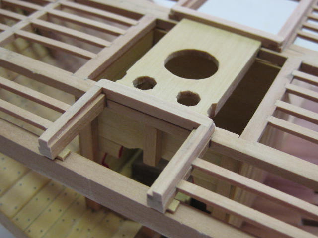
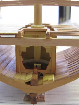
Thanks Pat. The Mainmast Partners on Vulture are rather unusual, being a wedge shape. There are four pieces to them : The Pump tubes fitted : Danny
- 268 replies
-
- 33
-
-
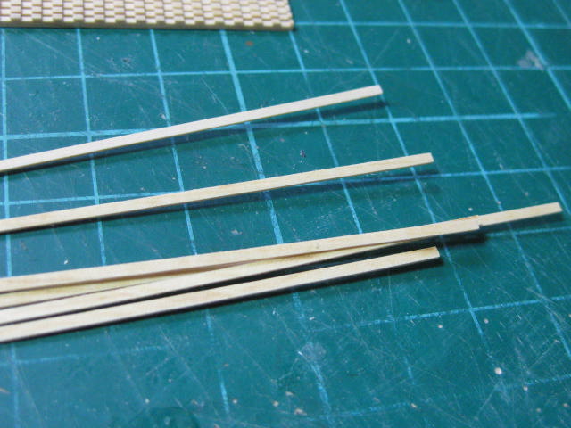
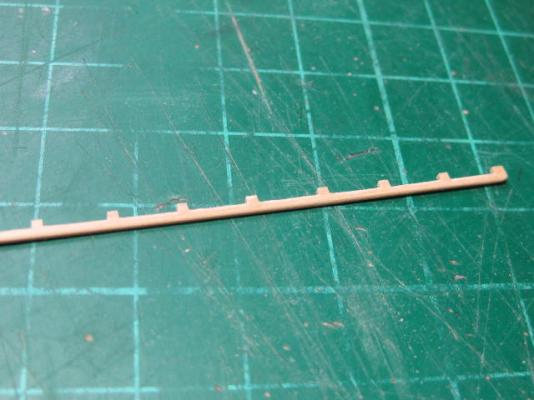
Thank you John, Mark, Nils, Grant, George and Greg . Oops, my mistake Greg - they are actually half that thickness (0.38mm) by 1.4mm wide. I used a 2 1/2" x 0.020" (1.0mm) kerf blade that I bought from Jim Byrnes (Model Machines). I can cut even thinner stock than that, depending on the type of timber. English Box will cut down to almost zero thickness . Danny
-
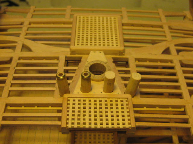
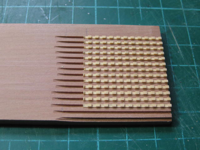
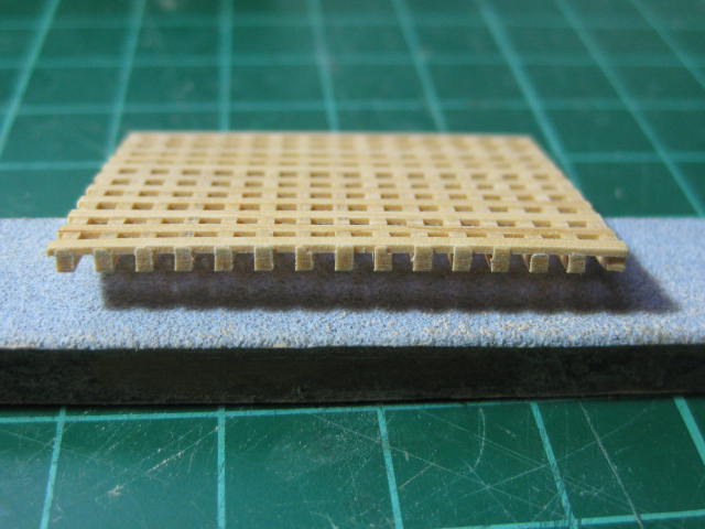
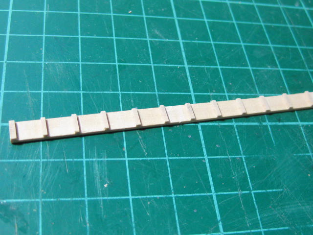
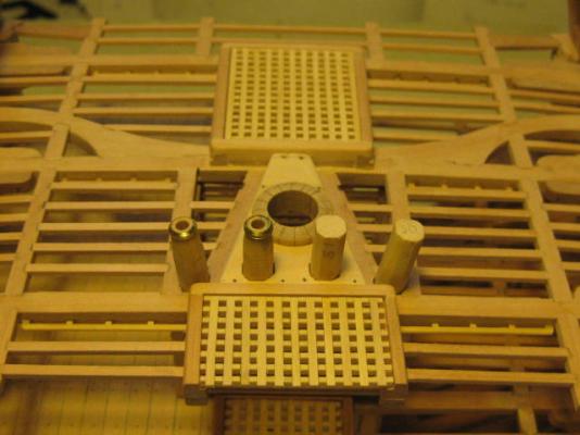
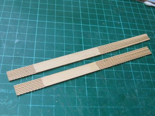
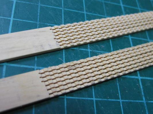
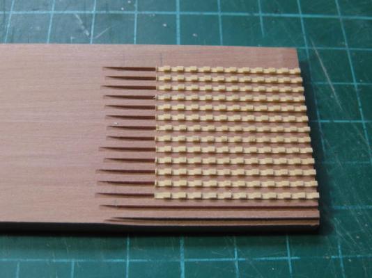
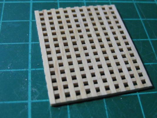
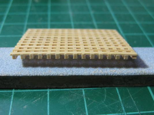
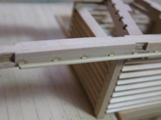
I've also made all the Gratings. Unlike the "store bought" gratings these are to the right scale. The athwartships pieces are a mere 3/4" thick (real size) which translates down to 0.38mm in 1:48 scale. All the pieces were cut and mortised using the Byrnes Table Saw and Micrometer Gauge : I made a Jig to aid in assembly : Danny

- 268 replies
-
- 44
-
-
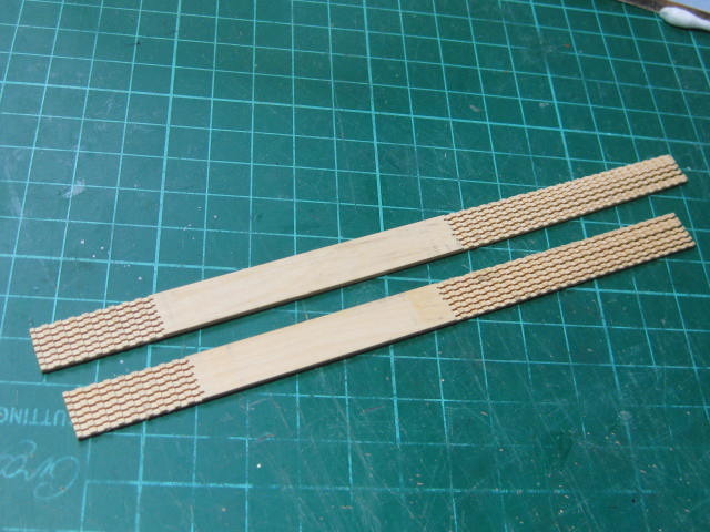
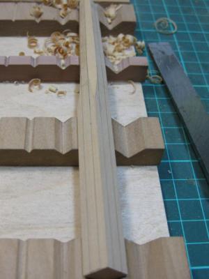
Thanks all for the wishes on my latest (and hopefully FINAL move ) . As I said earlier my computer didn't survive intact, but after a couple of trips to the local Computer Guy I'm finally back on-line . I've been doing a bit of work on the Cross-section in between all the usual unpacking, setting up a (sort of so far) workshop etc. Here's the update to where I am now - although I'm a bit further on that what I'm showing here. I've decided to install the Hammock Battens on this model. I left them off the full model as they would have been all but invisible. First I cut some English Box into the profile sections. Then I sliced off the appropriate widths : Next I rounded off the sections of batten, cut them to length and fitted them into the areas where they would have been : Danny


- 268 replies
-
- 20
-
-
Hi all, I've moved house and have my workshop up and running again (in a fashion, lots of unpacking still to do). Work has resumed on the cross-section, but updates will need to wait a few days as my computer didn't survive the move intact. Should get it back from the shop soon. Danny
- 268 replies
-
- 11
-
-
Thanks for the wishes guys . That's what happens when "life" throws you a couple of curve-balls Carl . Danny
-
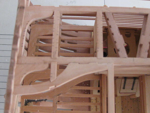
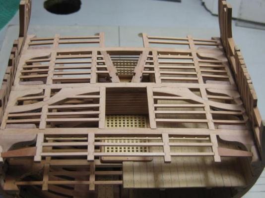
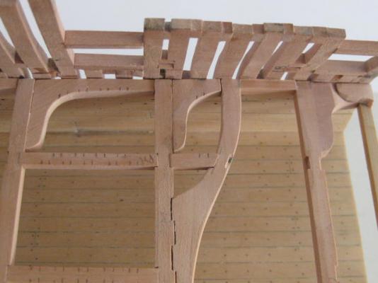
Something like that Greg . It's used where the strains on the planking are greatest, such as the Spirketting and Deck Planking around the Gunports, and the Wales. Thanks to all the others for their comments and Likes . I started the Upper Deck framing the same way as the lower deck by temporarily installing the three Beams. Next I made the Upper Deck Main Mast Partners. You may remember from the full model that these differ significantly from some of the earlier Swan Class ships in that they are angled : I've also made and (once again temporarily) fitted the Lodging Knees and most of the Carlings, some of which can be seen below marked out for the Ledges. All these pieces will be removed later to cut the various mortices : Last thing for now I've made up the Main Topsail Sheet Bitt Pins : This will be the last I can do on my model for a little while as I'm ONCE AGAIN (6th time in 7 years) moving house, having sold my caravan where I've been living for the past couple of years (I just got word that the money has been deposited into my account ) and I'll be moving back into my own house. Ironically, this is where I first built my workshop . See you all in a couple of weeks when I get settled in again. Danny


- 268 replies
-
- 34
-
-
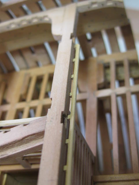
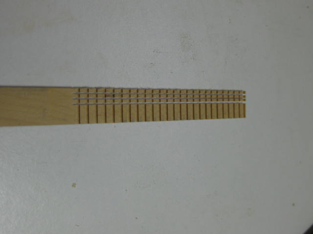
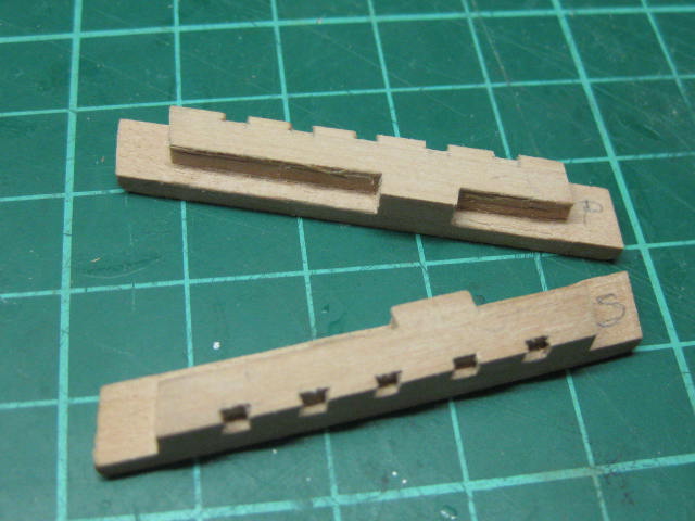
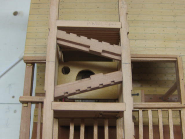
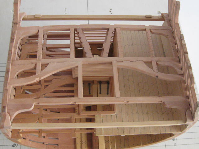
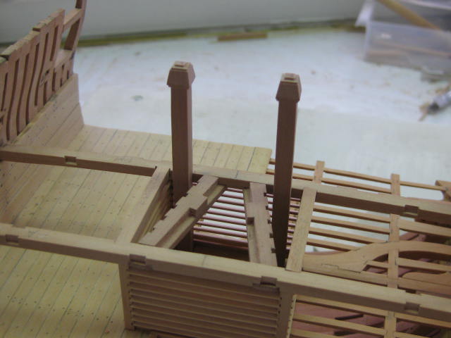
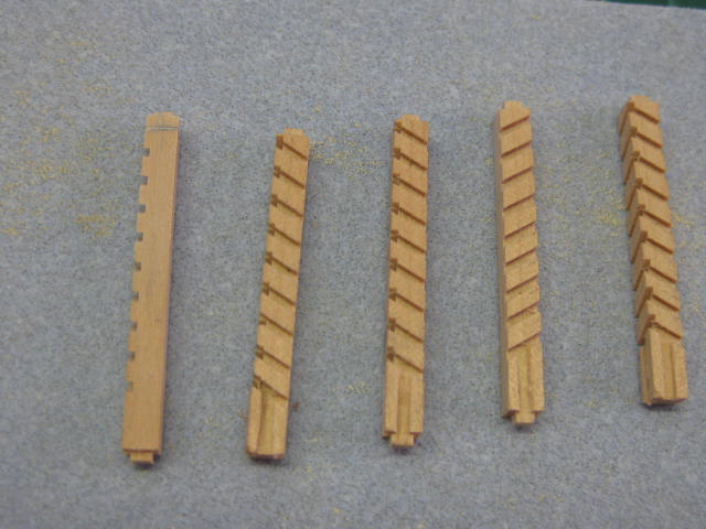
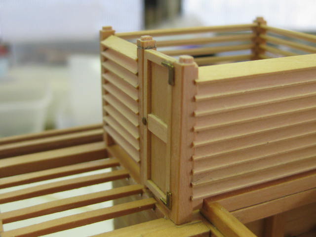
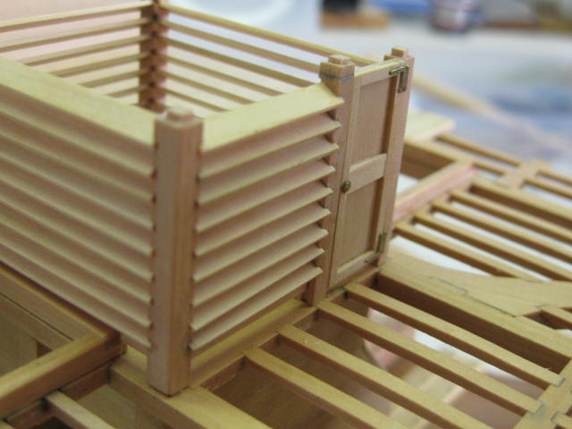
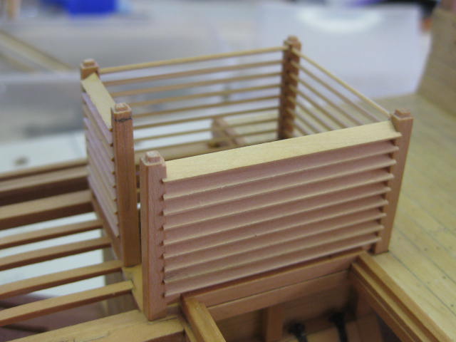
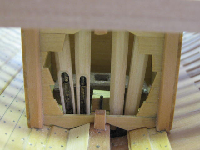
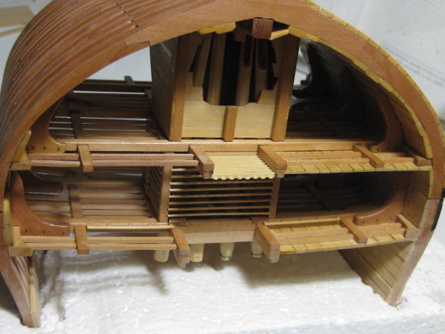
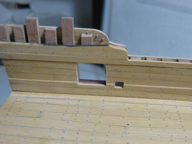
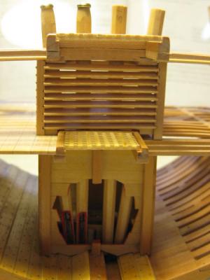
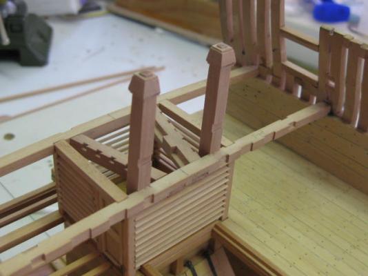
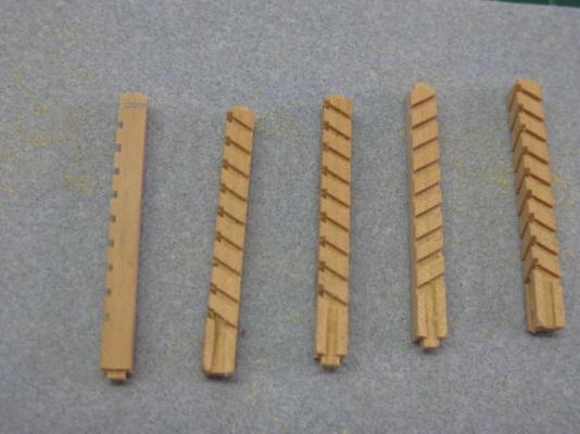
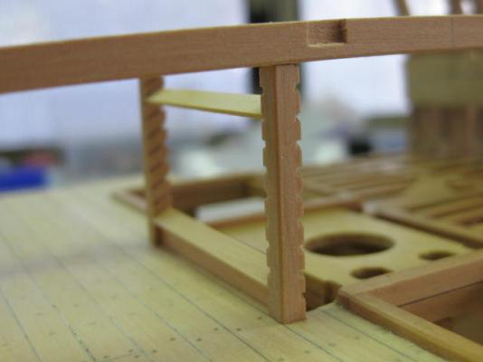
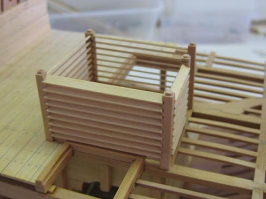
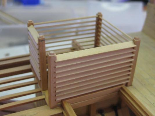
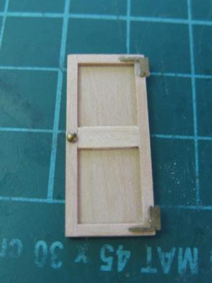
You may have noticed in the previous post that I've also done the Upper Well. This is a fairly tricky assembly to get right. First I temporarily fitted the two upper deck beams above the well, then I cut and rebated the five well stanchions. When these were all adjusted for a good fit I cut the rebates for the louvres at a 30 degree angle on the table saw : After cutting the louvres (which are 0.8mm thick by 3.18mm wide) I glued one at the top and one at the bottom between two stanchions in situ : Then I glued in the rest of the louvres off the ship - they all fitted very well. Some pics of all the louvres fitted and the well in position (not glued in yet) : There is an access door in the forward Starboard corner. I glued several thin strips to a flat piece of stock for the framing, and added a handle and hinges from the PE set : The door fitted : Danny


- 268 replies
-
- 30
-
-
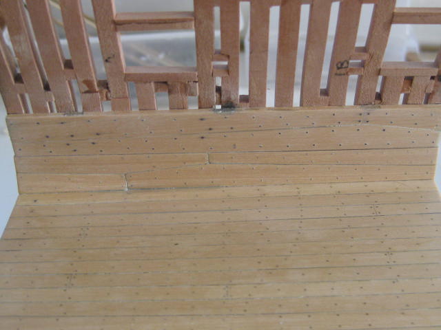
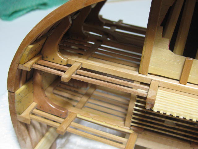
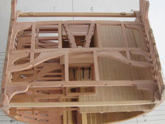
I've finished the lower deck planking, and also the two strakes of Spirketting below the Upper Deck Clamp. Some cleaning up and a coat of finish still need to be done, but I'm leaving that until after the knees are fitted : Danny

- 268 replies
-
- 27
-
-
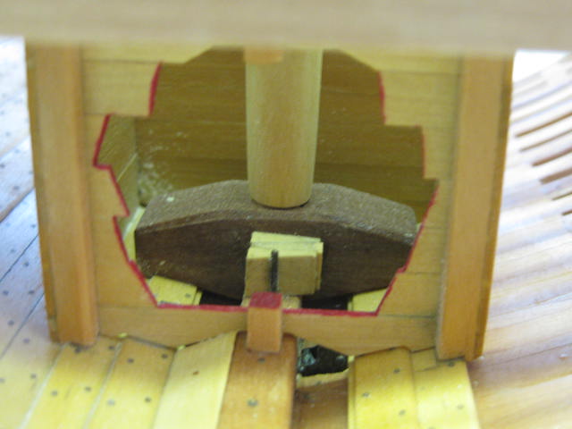
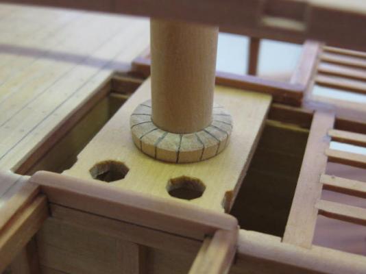
Greg, you've pretty well nailed it - the wedges around the mast on the lower deck as well as those at the heel of the mast are used for the adjustment of the rake of the mast fore-aft, the partners in the Upper Deck are fixed and the lower part of the mast can pivot around them. Apart from some very slight adjustment athwartships to get the mast vertical in that plane no further adjustment would be necessary. The mast could be raked fore-aft to make the most of the sailing qualities of each individual ship in certain circumstances. Note that I've done a bit of "fudging" on the wedges. These shouldn't have a step in the middle - I've done that for ease of fitting, as the step covers the hole in the mast partner for aesthetic reasons. Danny
-
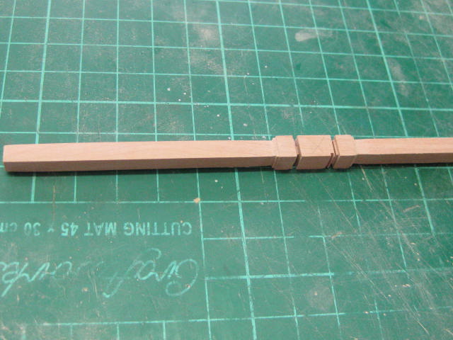
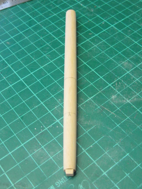
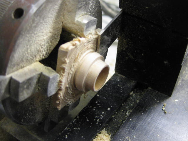
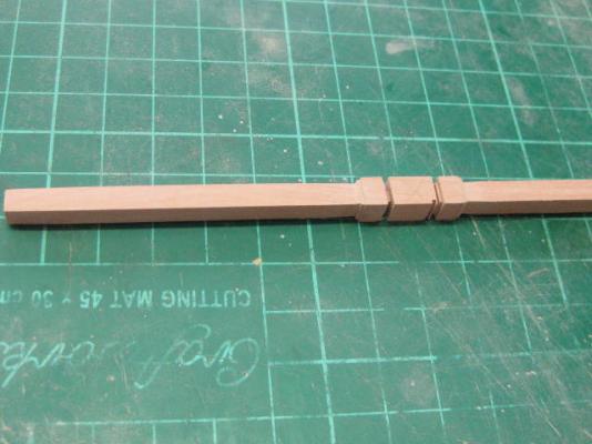
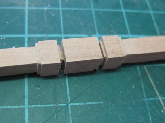
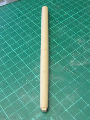
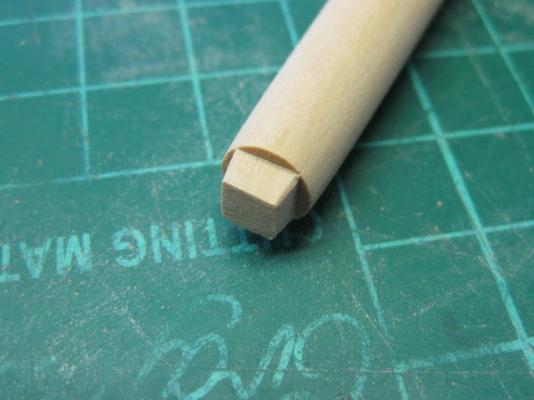
Thanks all for the kind words, and thanks again Greg for the extra PE pieces - they made work a fair bit easier . Sorry about the length of time between updates, but I had computer issues (AGAIN - gotta get a new one ) . It's time to make the Main Mast, or a stump thereof anyway. I tapered and rounded it in similar fashion to the masts and yards on the full model - first marking the tapers, then sanding them to shape on the disc sander, remarking the edges of the octagons using the 7-10-7 method, cutting the octagons with a sharp chisel while supporting the mast in my jig, then finally rounding them with various grits of sandpaper on a cork block : Next I cut the step in for the heel : I turned the mast Wedges in a single piece. There is one for each deck : Some views of the mast and wedges temporarily fitted to ensure correct alignment : Danny


- 268 replies
-
- 35
-
-
Hi Druxey, I don't know HOW I've missed seeing this build up until now - excellent work, as is to be expected from one of the real masters of this hobby . I'll be checking in more frequently now . I've used the same techniques when building my last two ship's boats (Vulture's and Supply's), and also the Longboat in the Bottle I built recently, all with good success, but nowhere near to the accuracy and execution of yours. Danny
- 641 replies
-
- 8
-
-
- greenwich hospital
- barge
- (and 1 more)
-
Hi Pat, nice soldering work . Without knowing anything about the temperatures involved in Resistance Soldering (less heat than Silver Soldering???) I would have suggested that you silver solder the plates onto the pins BEFORE resistance soldering the pins to the guns. Maybe that's still possible if you can remove the pins again? Otherwise - don't stress about using a plate at all. If you drill the holes in the Stanchions to the right depth the pin will bottom out at the right height . Another alternative - CA or Epoxy the plates to the pins. Danny
- 517 replies
-
- 3
-
-
- Endeavour
- Artesania Latina
- (and 1 more)
-
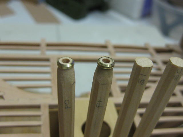
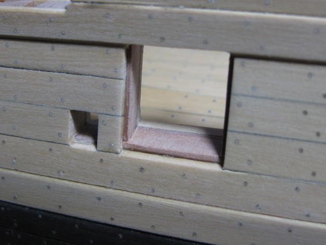
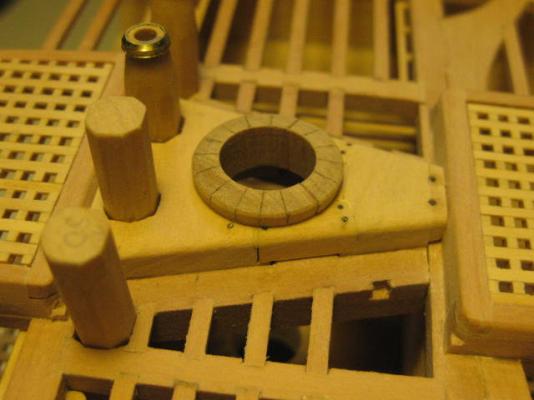
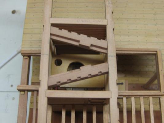
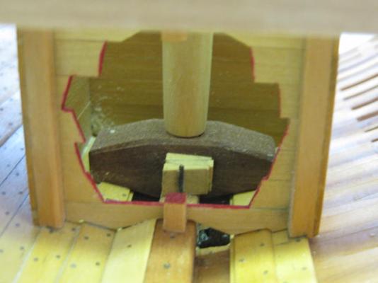
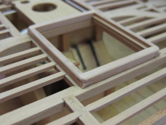
Thanks for all the kind comments, and the input about the painted cutaways. I've decided to go ahead and paint the cutaways red : The pump tubes are tapered at their tops, and have a re-inforcing band around the extremity. I turned these from brass tube. I didn't bother adding this detail to the unseen Starboard tubes : I've also made and fitted the Hatch Coamings for this deck. These are 6" wide by 5" deep. The Coamings (the fore-aft pieces which are also named this way) have a 3" by 2 1/2" rebate for the Gratings. The Head Ledges (the athwartships pieces) are rounded slightly to match the round-up of the deck. Each corner is rebated into it's partner and rounded to the level of the top of the planking : Note that I have a temporary "beam" beneath the outer ends of the Carlings for stability. This will be removed when I have finished planking this deck. Danny


- 268 replies
-
- 27
-
-
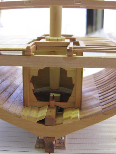
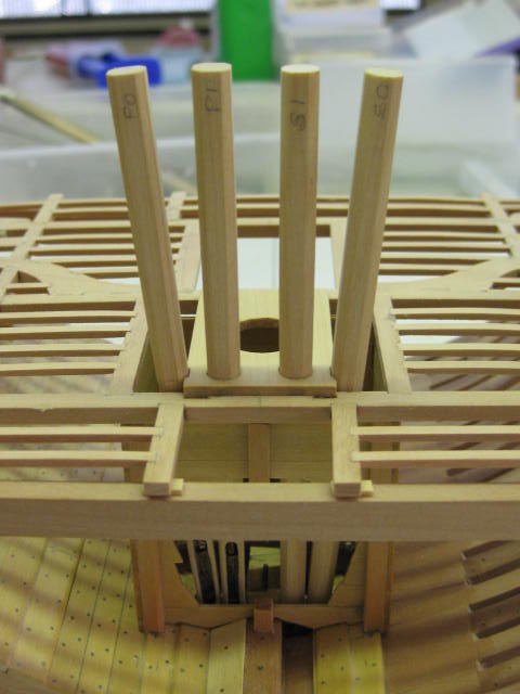
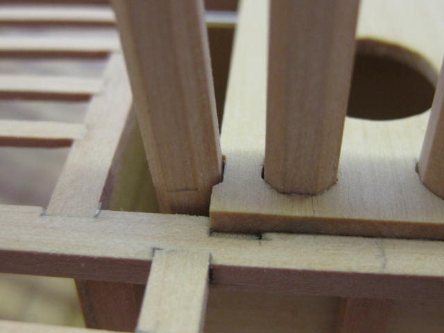
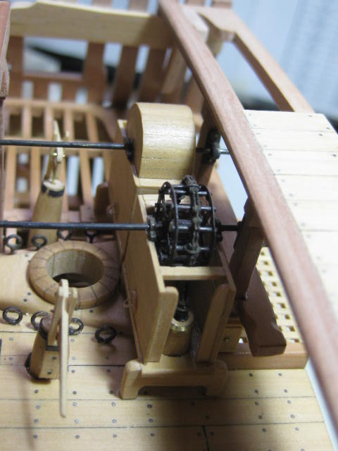
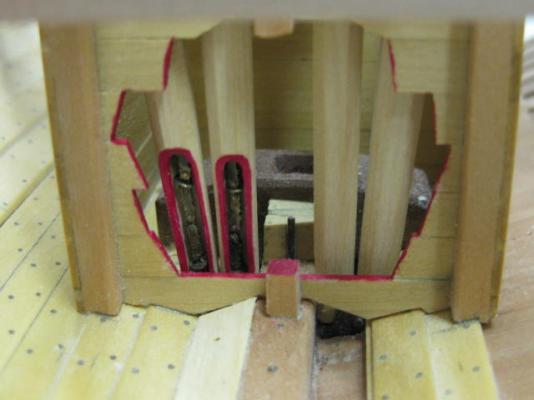
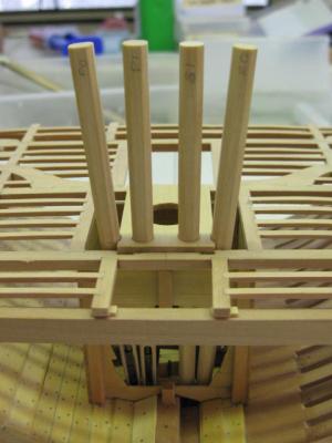
Thanks Greg and John. They're open to show the chain Greg. See pics below. I'm half wondering whether I should paint the cuts red to show that they are indeed a cut-away (and the same with the cut-outs in the aft end of the well, also any future cut-aways). Thoughts anybody? I've temporarily fitted the four chain pump tubes to make sure I have all the angles etc correct. They fit quite a bit better than the full model's tubes . : The outer tubes needed a small cutout in the mast partner to get the distance between the tops correct. I didn't do this on the full model and had a few issues later on. TFFM doesn't specify this : Danny


- 268 replies
-
- 21
-
-
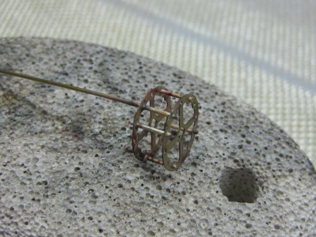
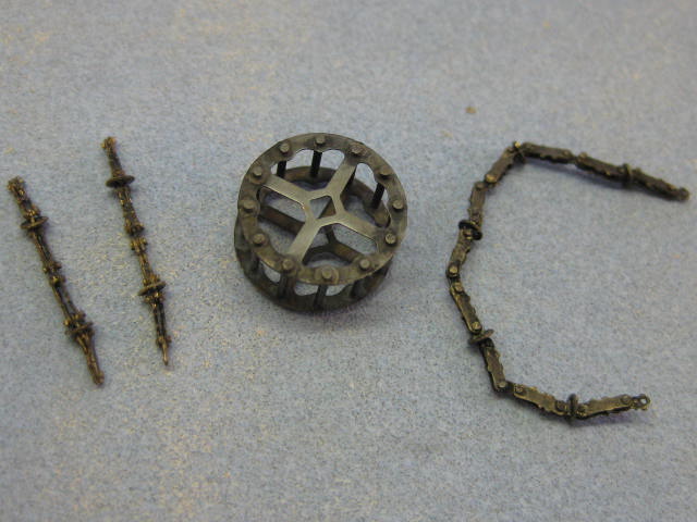
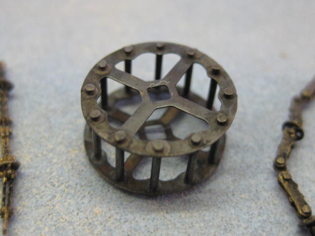
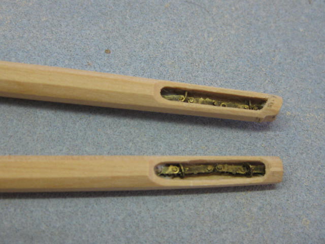
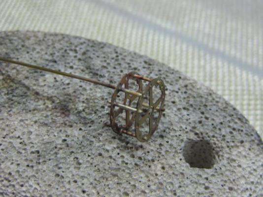
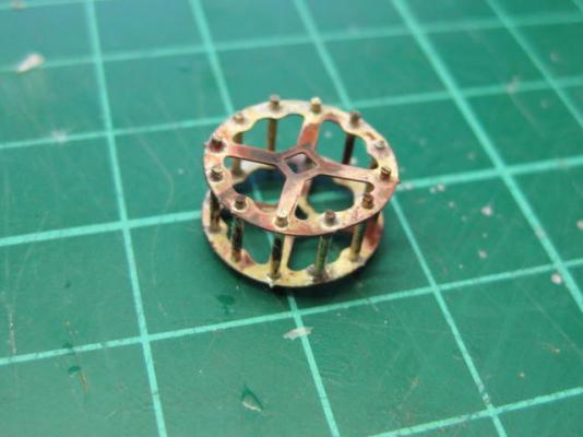
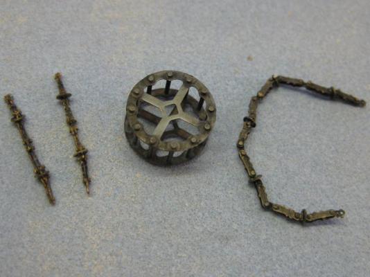
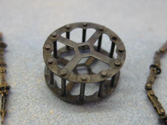
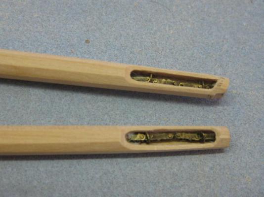
Thank you Druxey, George, Pat, Albert, Maury, Greg and Wes (welcome back) . Pat, I'm taking far more time and effort in getting every small piece spot-on, as it's a lot more visible than in the full model. I'm also adding a bit more detail. I've made up one of the Chain Pump Sprockets - the other one will be covered by the Cistern Hood and therefore invisible. The bars are silver-soldered into the PE wheels : I've also made up three lengths of the Chain, again using pieces from the PE set. The longer one will fit over the sprocket at the top, and the two shorter lengths fit into two cut-outs I've made into the lower ends of the pump tubes : Danny
- 268 replies
-
- 26
-