


Dan Vadas
-
Posts
3,261 -
Joined
-
Last visited
Content Type
Profiles
Forums
Gallery
Events
Posts posted by Dan Vadas
-
-
Hatch Coamings and Companions
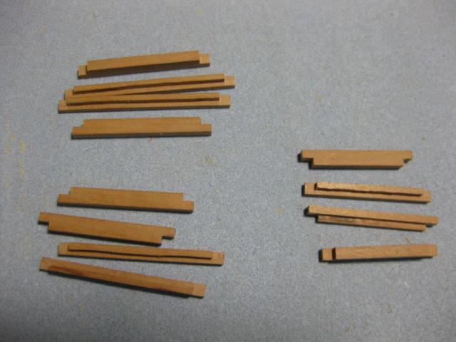
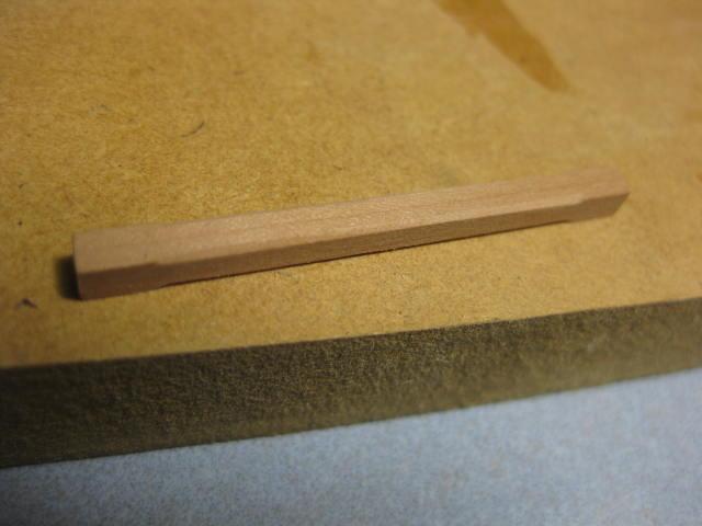
The Hatch Coamings (surrounds) on the lower deck are 6" wide and 5" deep. They have a 3" deep by 2 1/2" wide rabbet to accept the hatch. The longitudinal members are also called Coamings (just to be confusing) and the athwartships ones are called Head-ledges. The head-ledges have a curve which matches that of the beams. I made these from thicker stock and sanded the curvature into them :
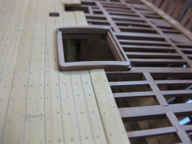
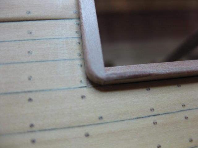
The corners of the coamings are rounded above the deck planks only :
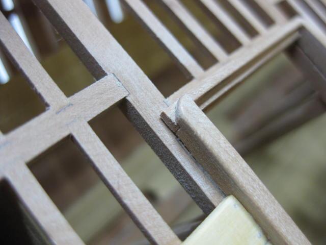
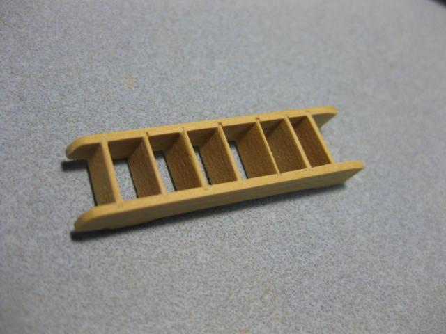
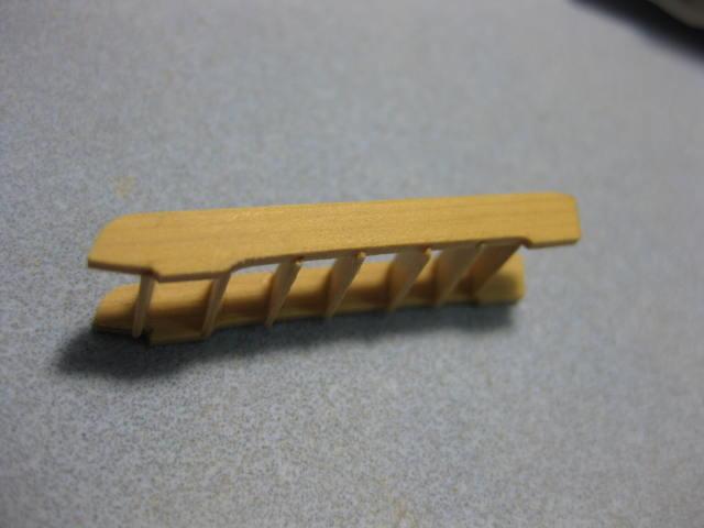
The rabbets in the Stiles were cut on the Byrnes saw using the Micrometer gauge. Then the Treads were cut on the saw and glued in. Note the shaping of the underside of the stiles :

-
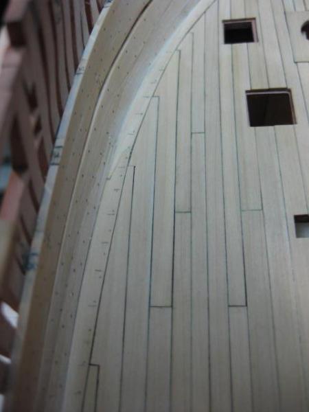
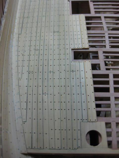
Lower Deck Treenailing
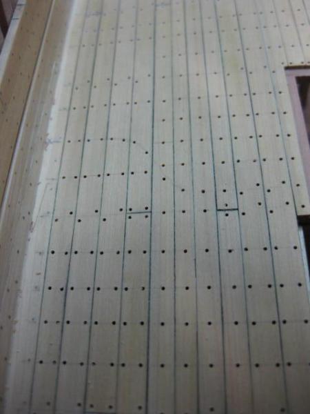
A couple of thousand treenails were drilled and fitted. The pattern varies depending on the width of the plank at a given point - those under 8" only get one nail, those between 8" and 10" have a single nail and double nail alternately, and those over 10" get all double nails :

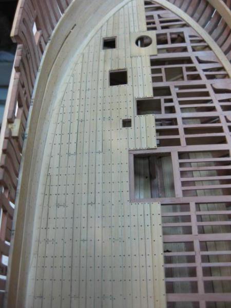
The deck is given a sanding with 150 grit and 400 grit paper :
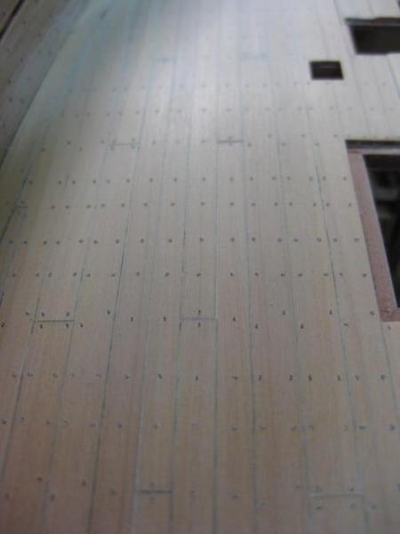
And finally two coats of Minwax Wipe-on Poly are applied :
-
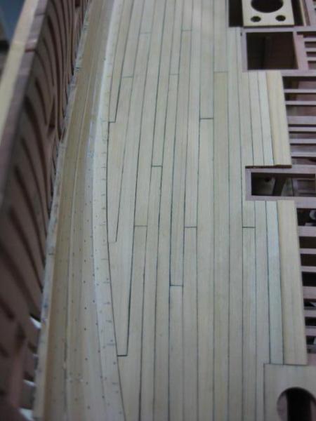
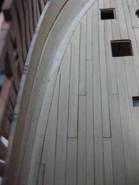
Hooked Planks
Some Hooked Planks were required in the bow and stern where the hull narrows significantly. This avoids a weak sharp point which cannot be nailed properly :

- gaoxiaoming, ken thomson, knightyo and 2 others
-
 5
5
-
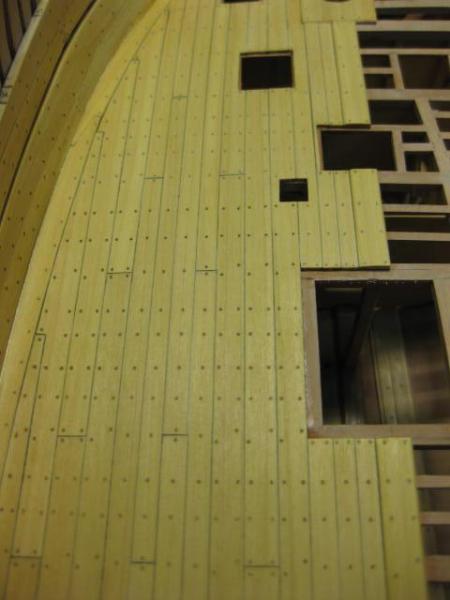
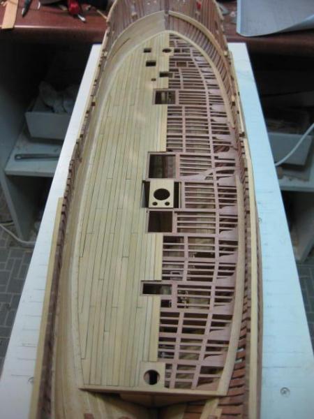
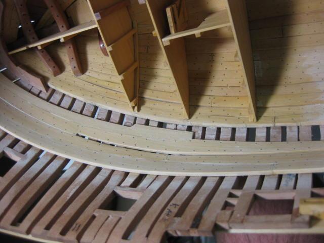
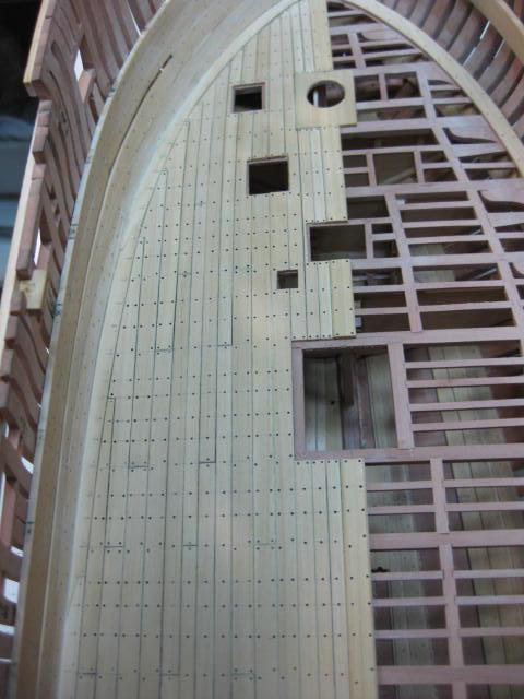
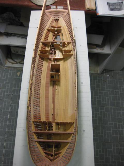
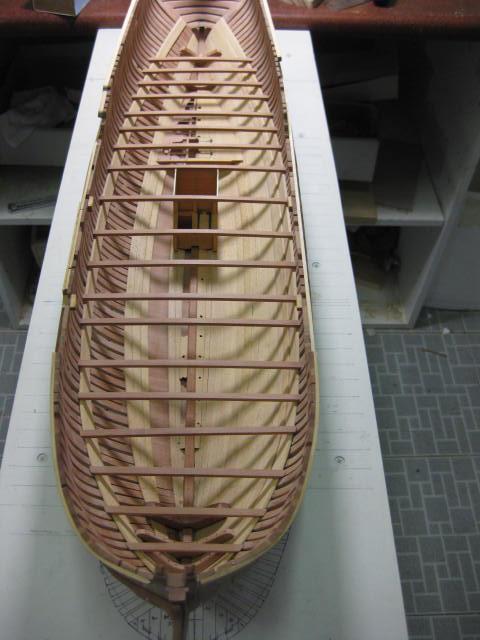
Lower Deck Planking
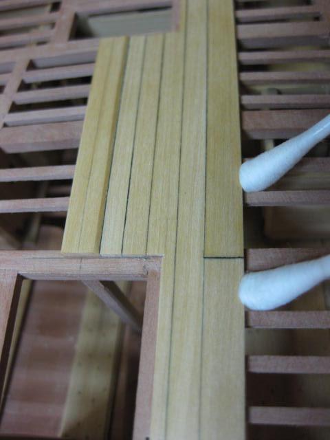
The first plank for the lower deck is the King Plank which runs down the centre line. It is 12" wide and 3" thick and sits 1" proud of the rest of the planking. It is chamfered on both sides to match the adjoining planks. "Caulking" is done on one edge and butt join with an Archival Ink pen :

The remaining planks are nominally 8" wide and 2" thick. Work continues outward :

The planks narrow toward the bow and stern between the Binding Strakes and Waterways :

- CiscoH and gaoxiaoming
-
2
-
Upper Deck Beams
The Upper Deck Beams are 9" wide by 7" deep and have a roundup of 6". There are 22 of them in total.
I mentioned earlier that I used a different method of cutting the Upper Deck Beams to save on timber wastage and time. Instead of shaping each beam from an oversize blank I cut them all to a slight oversize on my scroll saw, dressed the top face and milled the bottom face as before.
I also made an improved version of the jig I use to mill the bottom faces :

Carling locations were marked and cut the same as the lower deck beams :
-
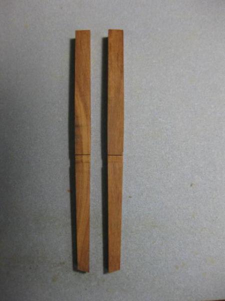
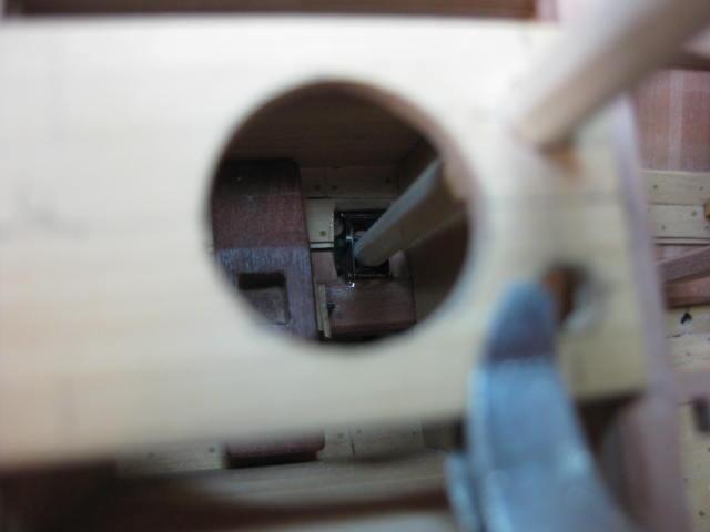
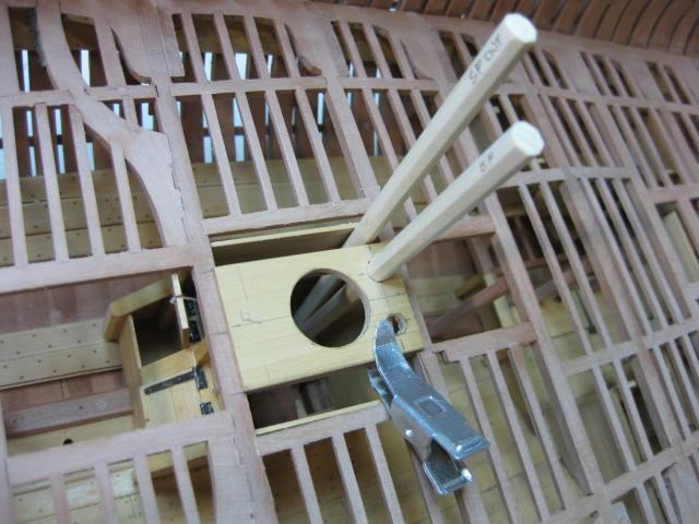
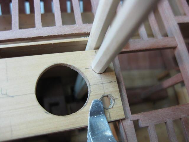
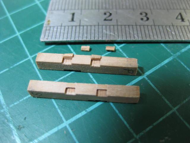
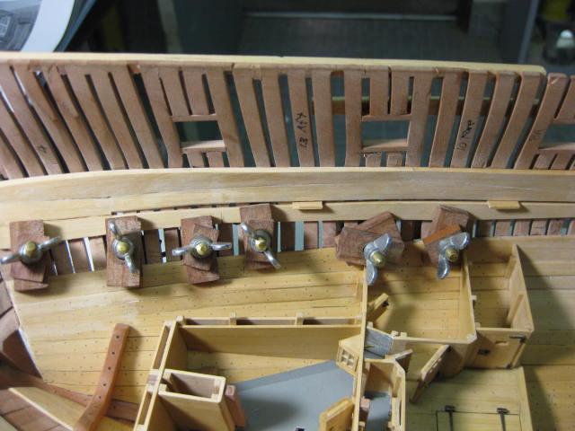
Riding Bitts - stage 1
The Riding Bitts are massive - 13" square - as they are subjected to a lot of forces from the Anchor Cables.
Again, I've jumped ahead a bit to enable me to cut the seats for them in the correct positions. I've only done the first stage of them so far.
They are made from Australian Cherry Ballart, as are all the other Bitts in the ship. It's a good hardwood with a very nice contrasting color, and was the only suitable timber of sufficient thickness I had on hand at the time :
-
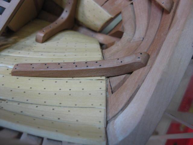
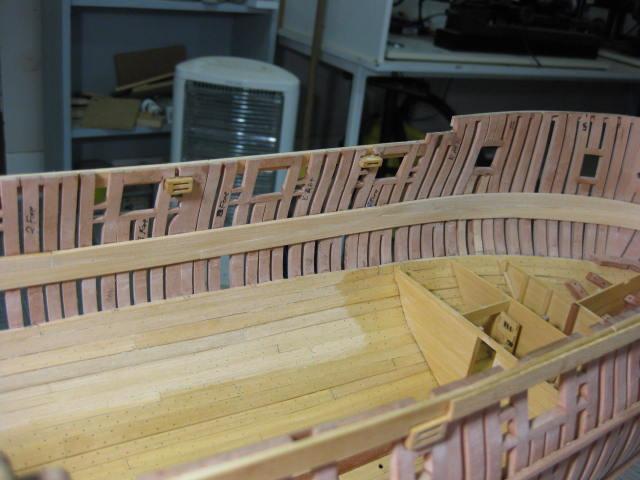
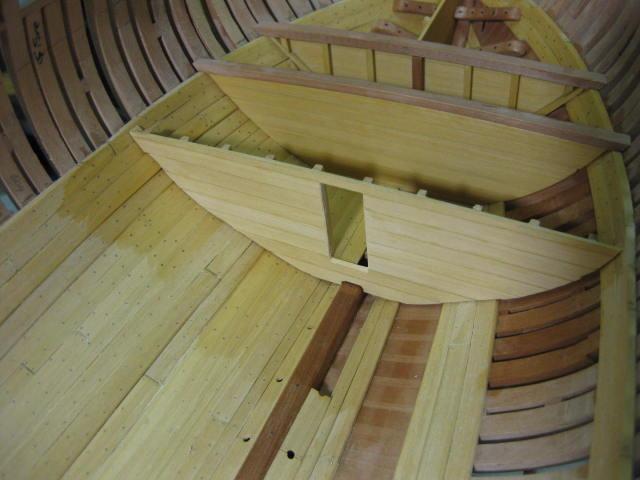
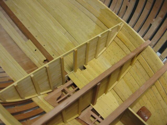
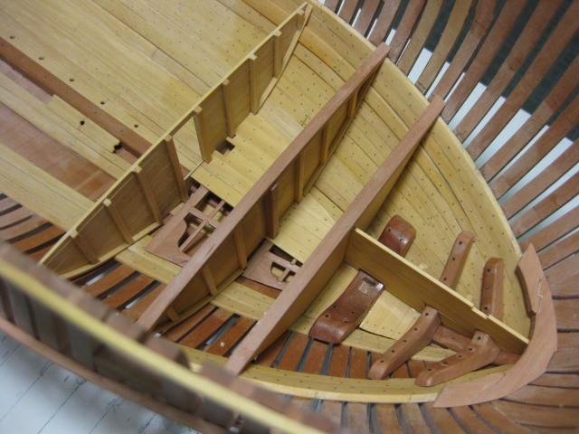
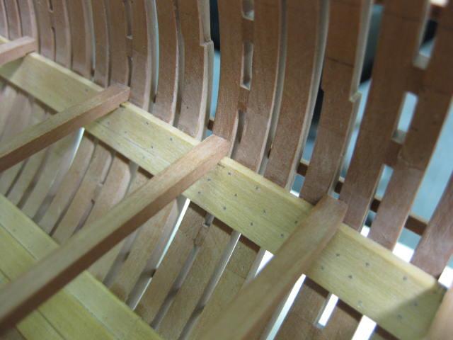
Lower Deck Waterways and Spirketting
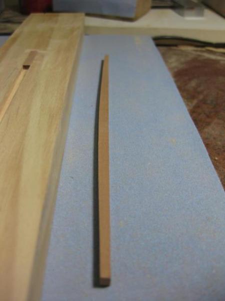
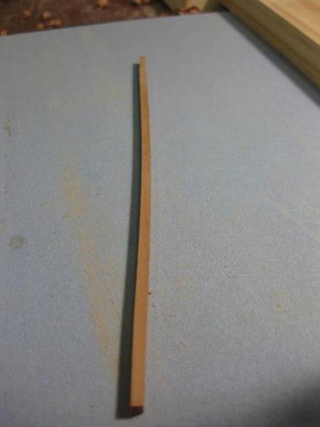
A Waterway, or gutter, runs the length of the lower deck. It has a slight inward slope on it's top face. The outer edge is bevelled to fit the angles of the frames where they make contact.
I cut these from wide stock, as the lateral bend needed was rather substantial :

Scarph joints are used to connect the lengths :
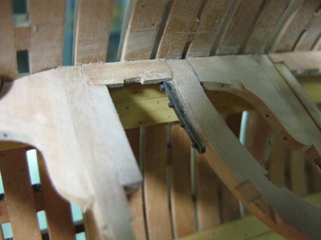
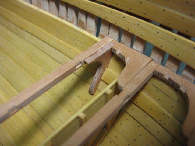
I have left out a section on the starboard side to show the Opposed Knees and Iron Knee below :
The Spirketting sits above the waterway and is worked in Top and Butt fashion :

-
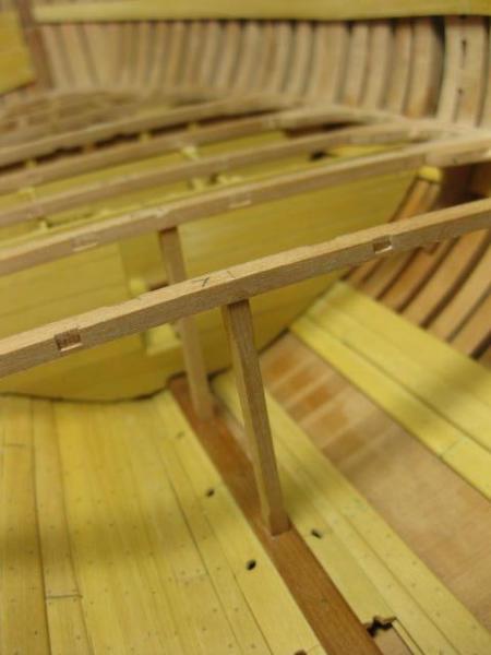
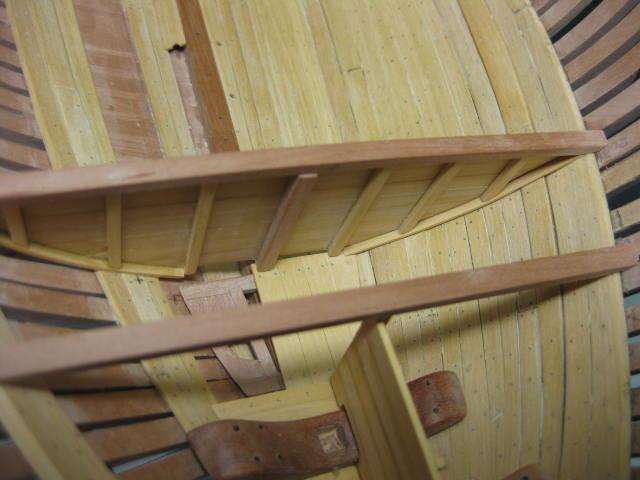
Sleepers
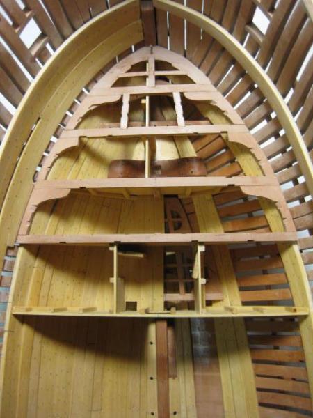
The Sleepers are two substantial "Knees" that brace the aft frames to the Transoms :
-
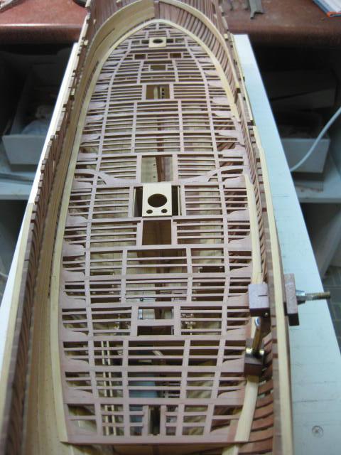
Chain Pump Inlets and Tubes Fitted
A template was made from the plans to hold the Chain Pump Tubes in position, and the Inlets were epoxied into the recesses :
-
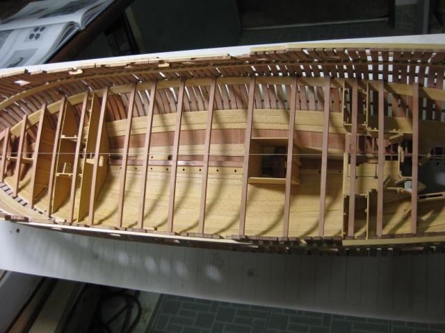
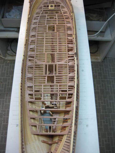
Lower Deck Beams, Carlings and Ledges
The Carlings were morticed for the Ledges in similar fashion to the beams :


-
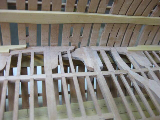
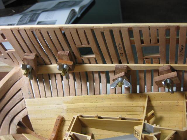
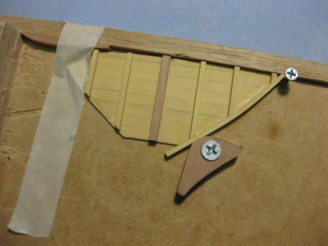
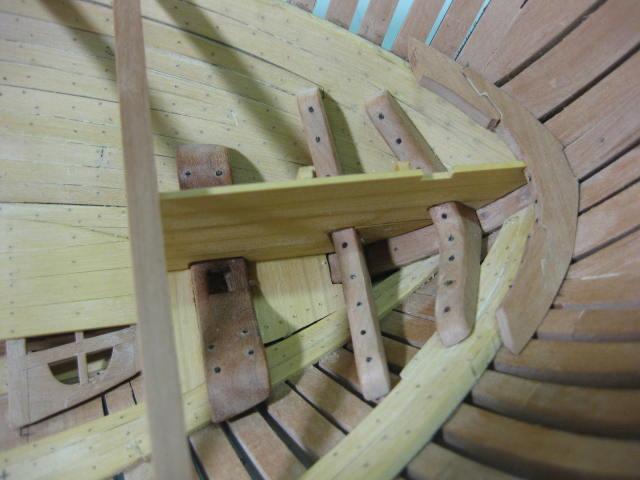
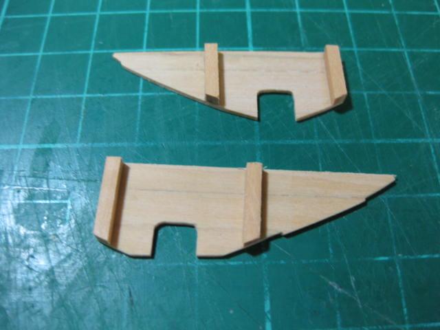
Opposed Knees, Beam Arms and Iron Knees
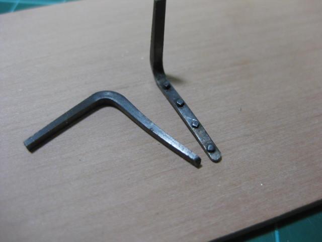
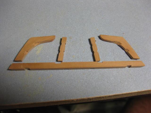
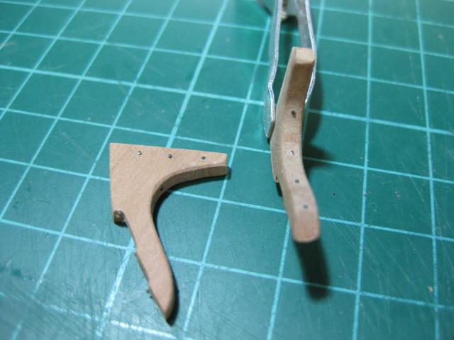
The Lodging Knees forward of the deadflat are on the aft side of the beams, those aft of the deadflat are on the forward side. Where they meet there are two "Opposed" Knees, one passing beneath the other. The lower one was made from extra-thick stock and filed to shape :
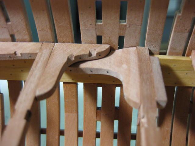
Two Beam Arms - substantial reinforcements - are fitted adjacent the Main Mast :
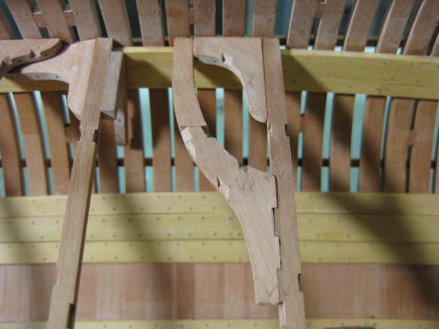

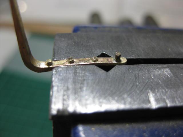
There is an Iron Knee at the aft end end of each beam arm. I made these from brass strip, tapered with a file. To simulate the square-headed bolts used to fasten them I silver soldered small pieces of brass wire to them and filed the heads square. They were then blackened and epoxied into the deck framing :
-
Pillars in the Hold
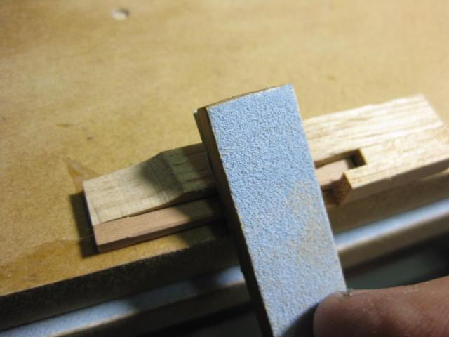
The centres of the beams are supported by Pillars. These are 6" square and have their corners chamfered. I made a small jig to ensure I sanded each one accurately :
-
Lodging and Hanging Knees
Each Beam is held in place by Knees - the horizontal ones are known as Lodging Knees and the vertical ones are Hanging Knees. They are bolted through the frames and into the beams.
The patterns for their shapes were taken from the diagrams in TFFM and modified to suit the actual shape of the hull using card templates.
I cheated a bit on the Ledge mortices in the lodging knees by cutting them on a 45 degree angle. The end result looks exactly the same :
Blackened brass wire was used for the "bolts". These were all cut from 0.5mm wire - they are about 3mm long - and were blackened before being inserted. A small drop of PVA on each one prevents them from falling out :
-
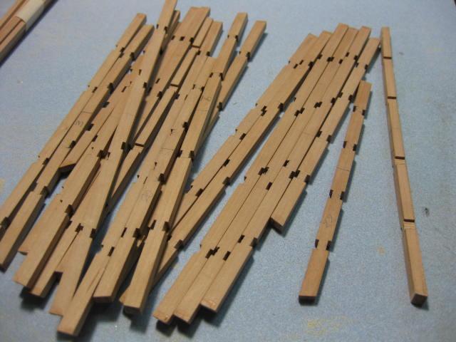
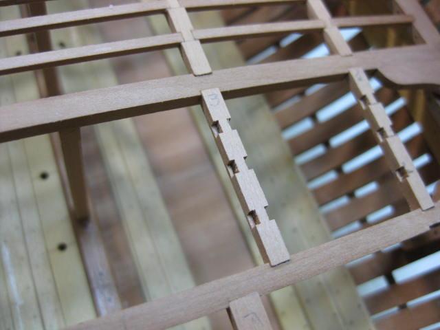
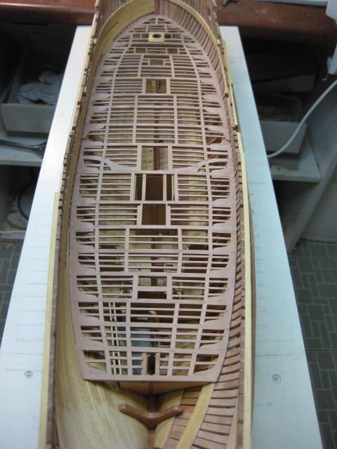
Lower Deck Beam Carling Mortices
It's now time to fit the Lower Deck Beams made earlier. First, the mortices need to be cut for the Carlings. To mark them out accurately I used a string line down the centre of the hull and measured outward from it to mark the positions of the mortices :
The blade height on the Byrnes saw was set to the depth of the mortices and the fence was set up to cut the left side of the mortice. Then a spacer of the correct thickness was slipped between the end of the timber and the fence to cut the right-hand side :
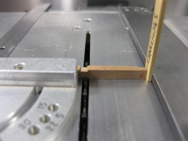
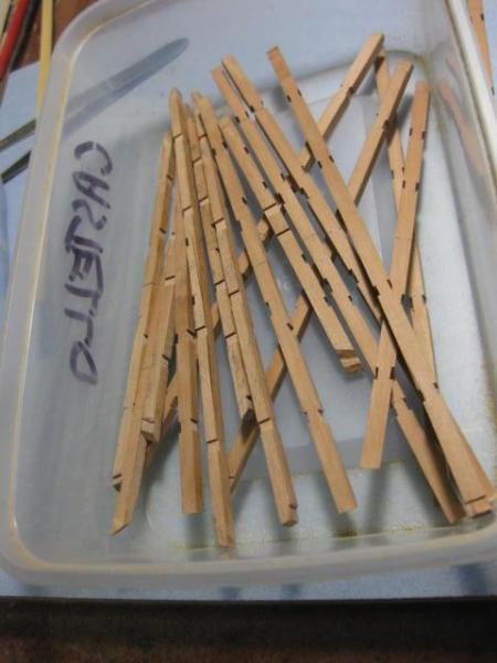
The Carlings are 4 1/2" thick whereas the Beams are 6", so instead of chiselling out each one I've cut them all the way through and will fit some "filler pieces" into the bottoms of the cuts to make up the difference. The blanks for these - there are about a hundred of them - were mass-produced on the Byrnes saw to the exact width of the mortice :
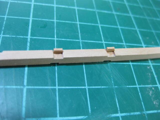
Once they are glued in and sanded flush the join becomes virtually invisible :


- gaoxiaoming and CiscoH
-
2
-
Upper Deck Clamps and Ceiling
With the Platform Rooms completed attention now turns to the Upper Deck Clamps. These are similar to the lower deck - they are also worked in Top and Butt fashion :
I made an error in measurement at the aft end - I hadn't allowed for the thickness of the deck beams when I marked out the tops of the clamps. This error wasn't discovered for quite a while, but I managed to fix it before any further harm was done.
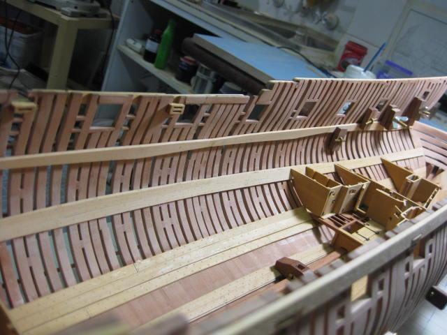
The Ceiling is similar to the Footwaling under the lower deck. There is an Air Space - a 2" gap for ventilation between frames - between the lower clamp and the upper strakes of the ceiling. Spacers are used to maintain the correct gap while the strakes are fitted :

Another Drop Plank has been cut into the forward end of the ceiling planks :
-
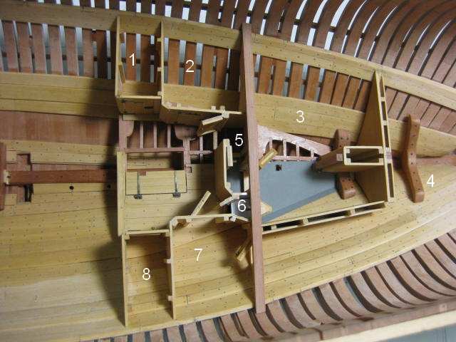
Aft Platform Rooms
These were all built in similar fashion to the forward platform rooms :

The Aft Platform Rooms are :
1. Marines Room
2. Captain's Storeroom
3. Magazine
4. Bread Room
5. Magazine Passageway
6. Lightroom
7. Steward's Room
8. Slops Room
- Jorge Diaz O and gaoxiaoming
-
2
-
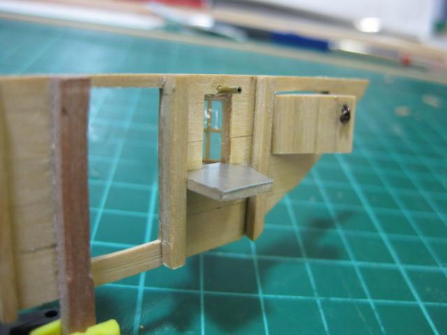
Finishing the Magazine
The shelf for the Lightroom lantern - it is covered with aluminium foil to simulate the polished surface of the inside of the room which helped reflect light into the magazine. The Bread Room door is on the port side - this was more like a "crawl-through" door, being only 18" high :
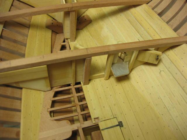
The door to the Magazine is very substantial in thickness - 6" - but very small otherwise ... 1' 9" wide and 3' 6" high. It is also filled with mortar in the real ship. No iron fittings were used anywhere near the magazine - all hinges and door locks etc were made of either brass or copper to prevent sparks.
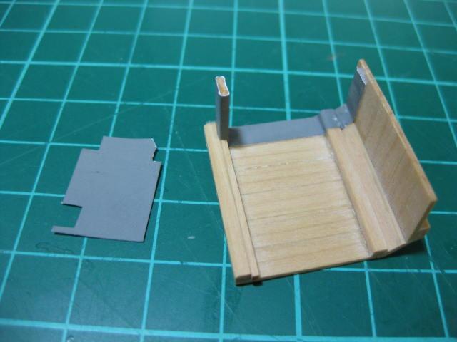
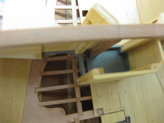
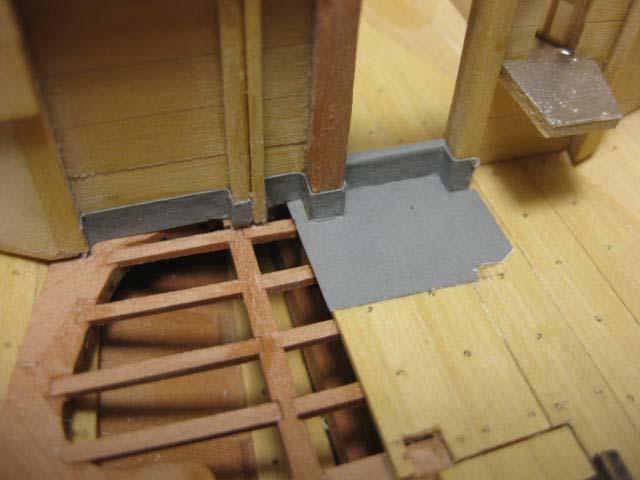
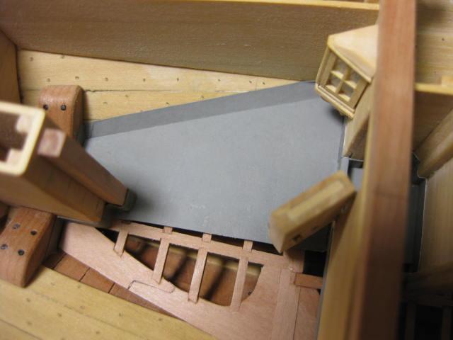
The floors of the magazine and passageway were sheathed in lead for two reasons - to keep out damp from the bilge, and to make cleaning up spilt powder easier. This sheathing extended up the walls by 5".
I used thin paper painted grey to simulate the lead :
-
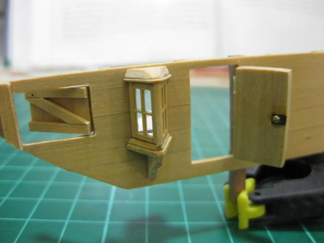
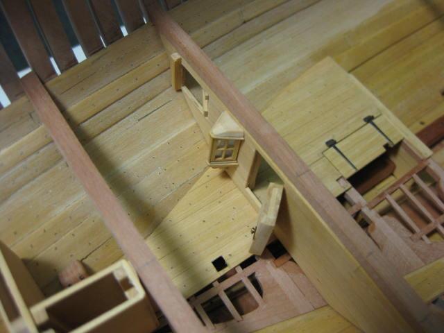
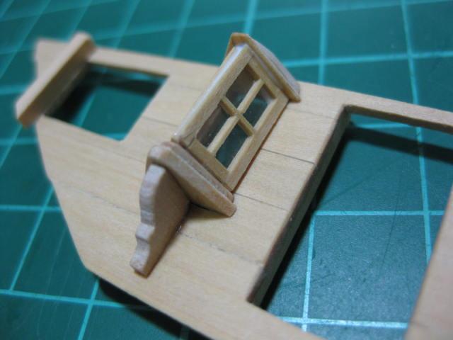
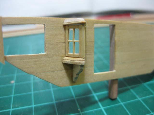
Lightroom
It was considered to be not a very good idea to have candles or lanterns inside the magazine (with good reason
 ) so a separate Light Room was fitted for illumination. This held a lantern accessible from outside the magazine itself, and was completely sealed off from it.
This was a very enjoyable part of the ship to build despite it's complexity (or perhaps BECAUSE of it
 ).
).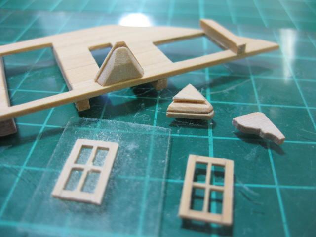
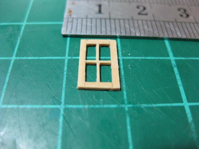
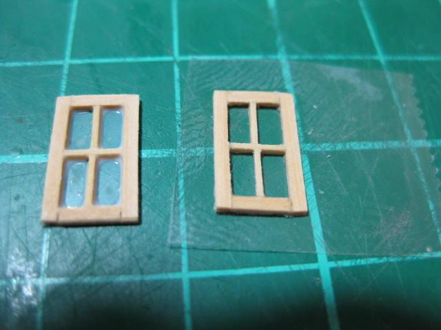
The glazing in the windows is clear Sellotape which has a coating of PVA on both sides to seal it. It simulates the rather frosted appearance of glass of the time quite well :
-
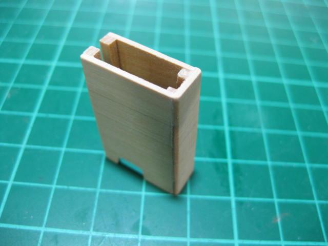
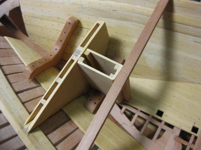
Magazine Bulkheads and Mizzen Boxing
The Magazine in the aft end has an athwartships bulkhead at each end. These were made in similar fashion to the other bulkheads, except that the outer end of the forward one is filled with "mortar" to help prevent any flame or spark from entering the magazine. I used a light colored wood filler to simulate this :
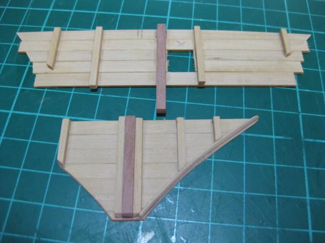
The Mizzen Mast has a Boxing surrounding it inside the magazine. The pics should be fairly self-explanatory as to it's construction :
-
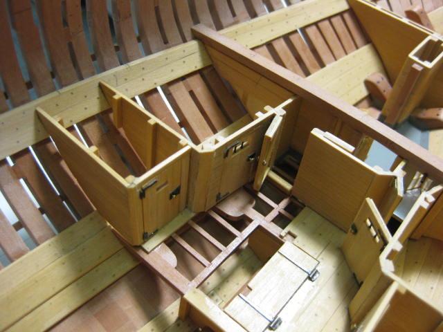
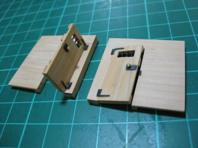
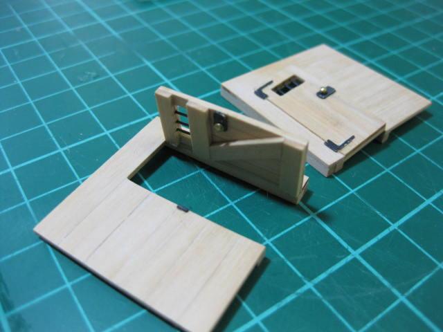
Block Room and Tar Room Bulkheads
The Block Room occupies the port side of the aftmost fore platform, and the Tar Room is on the starboard side.
I spot-glued the doors into the bulkheads to check their fit and sanded them slightly where needed :


Then I removed the doors again and fitted the hardware. I've left the Block Room one fully open and the Tar Room one slightly ajar for aesthetic reasons :
-
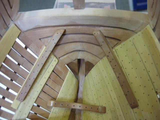
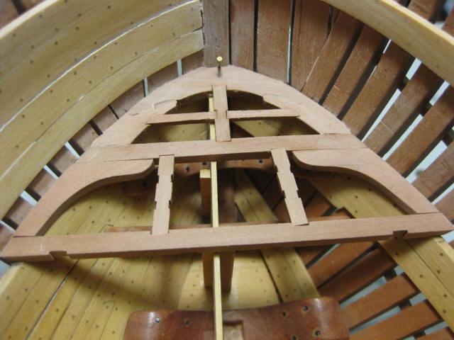
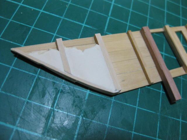
Lower Deck Hook
The Lower Deck Hook is a slightly modified version of the diagram in TFFM. It has two Hooked Scarph joints :
-
Fore Platform and Bulkheads
There are three separate Fore Platform floors - the fore and aft floors are on a similar line, but the central one (the Coal Hole) is 1 foot lower. Note that there are two parts to the fore floor. It is intersected by the Foremast Step.
These were made in similar fashion to the Aft Platform :
Notches have been cut into the aft ends of the planks to accept the Riding Bitts and bulkhead stanchions :

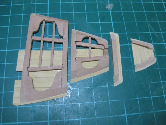
The Bulkheads are made by first using card templates to get the hull shape, then edge gluing as many planks together as necessary, gluing on the stanchions and sanding their bottom ends to shape, and finally fitting a lower rail. Much dry-fitting involved here :

- rth385, cpt. Tom and Senior ole salt
-
3
-
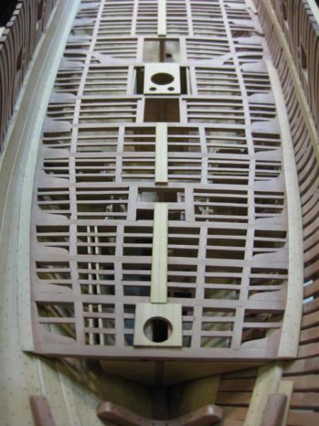
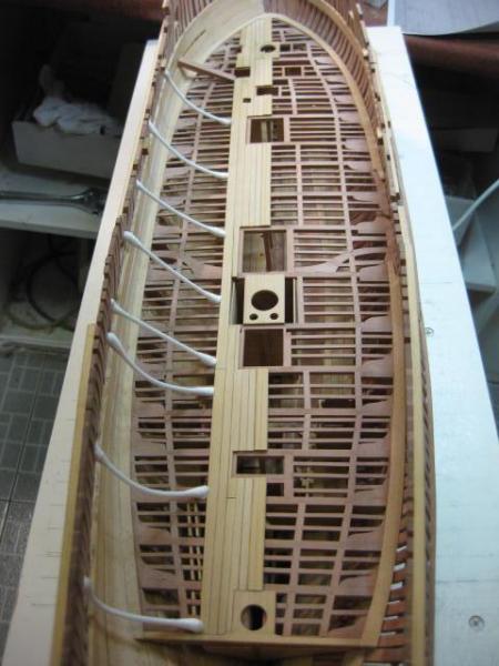
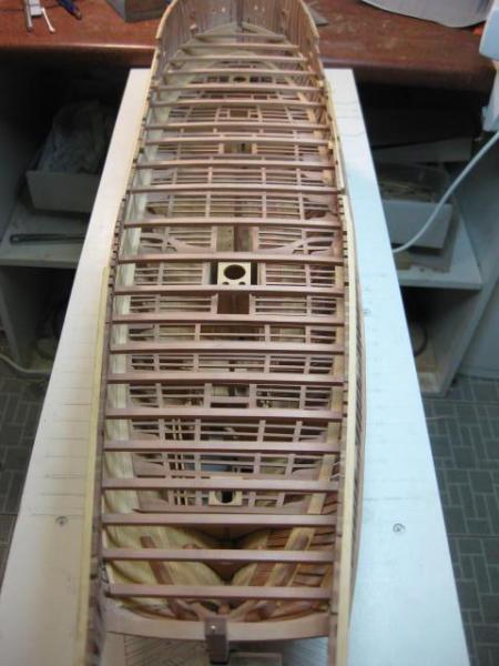
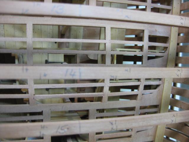
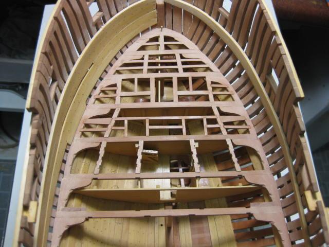
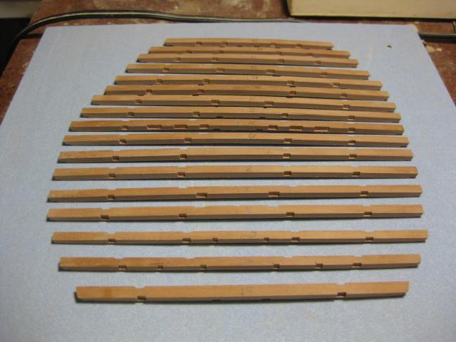
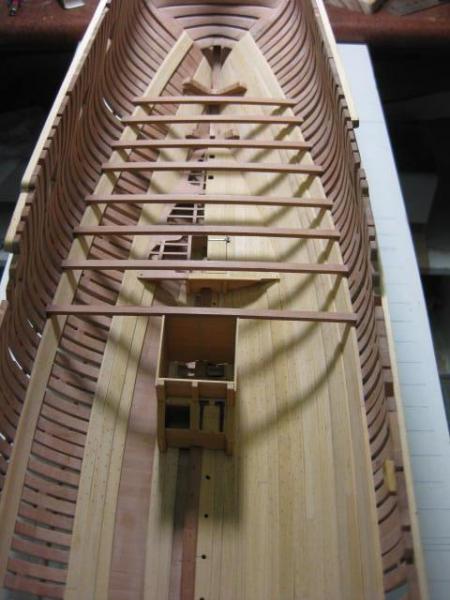
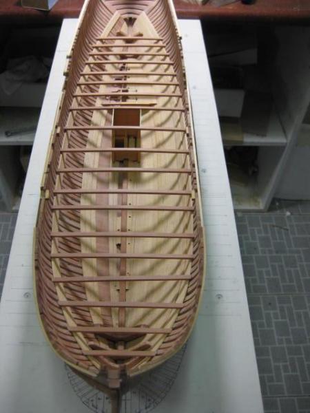
Lower Deck Beams
Occasionally one needs to jump a fair way ahead of the section being worked on at the moment. Some of the Lower Deck Beams needed to be made now in order to shape the tops of the bulkheads that are the next things to be built. It was just as easy to make ALL the Beams while I was set up for it.
The Lower Deck Beams are 8" wide and 6" deep in section. They have a 3" roundup over their length.
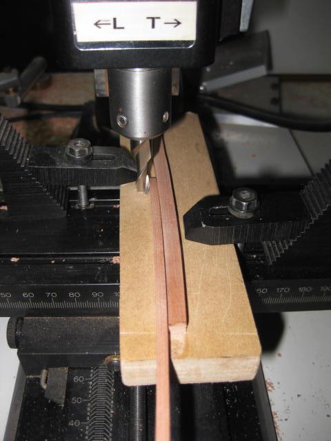
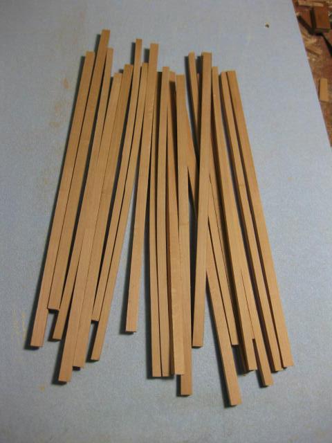
I made these ones as per instructions in TFFM by cutting blanks that were 8" thick and 9" deep, chiselling and sanding the top edge to the shape of the roundup, and finally thicknessing them in the Mill :

I found this method rather wasteful of timber, not to mention time, and later used a different method which had virtually no waste and was much quicker. This method is shown in the Upper Deck Beams post.
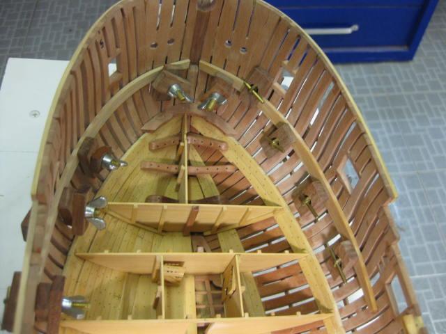
The beams are set 1" into the clamps. The easiest way to achieve this is to take the 1" off the ends of the beams themselves - the final result looks exactly the same. This avoids a LOT of VERY careful measuring and cutting into the clamps themselves - I'm not THAT good at something like that
.
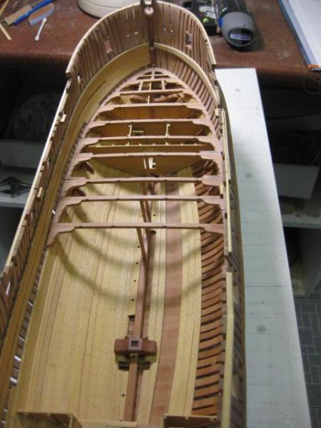
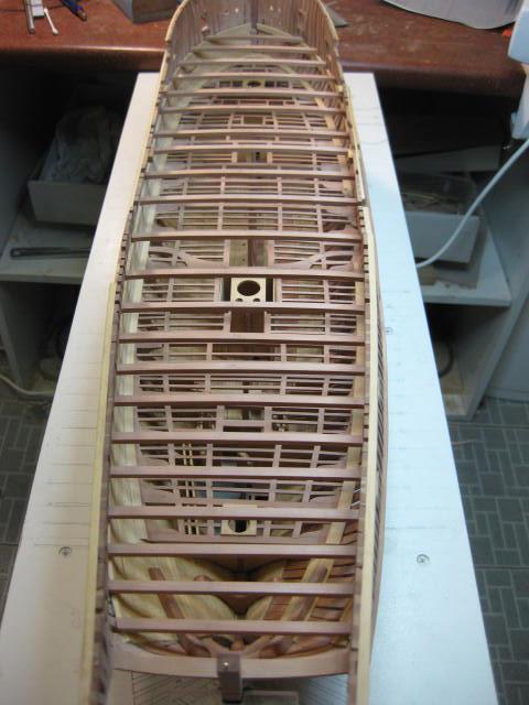
All the lower deck beams temporarily glued into place :
-
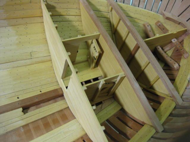
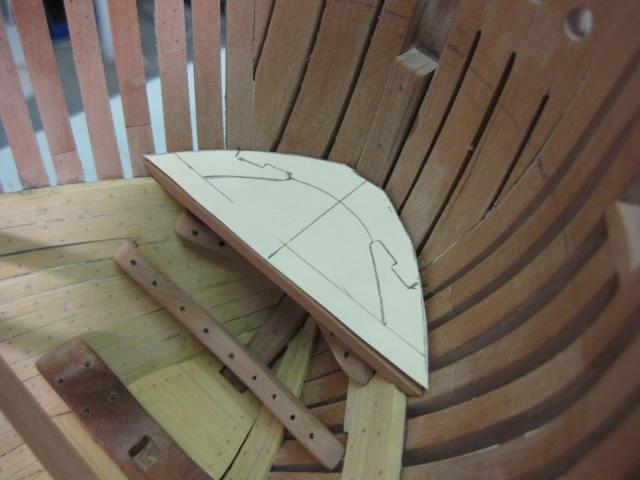
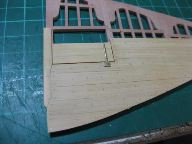
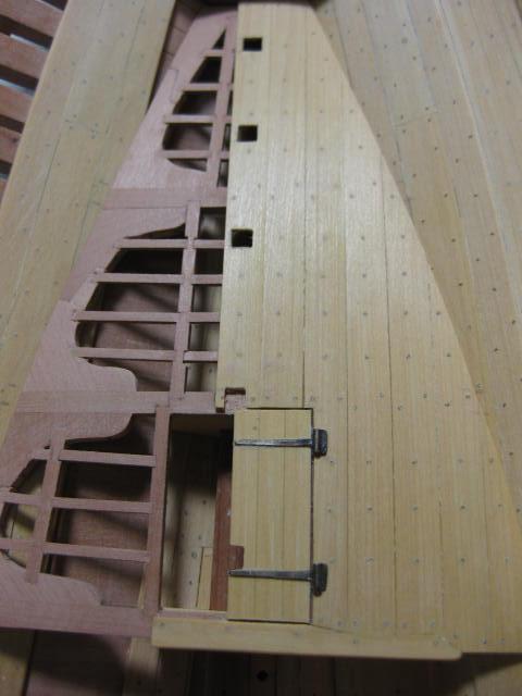
Aft Platform Bulkheads and Spirit Room Hatch
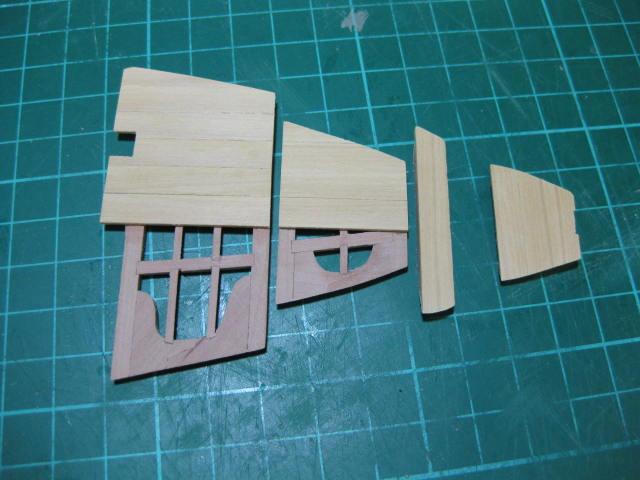
There are two bulkheads beneath the fore and aft floor of the aft platform. I made these to go a little past the centre line of the hull. Card templates were once again used to get their shapes :
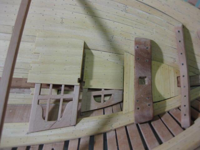
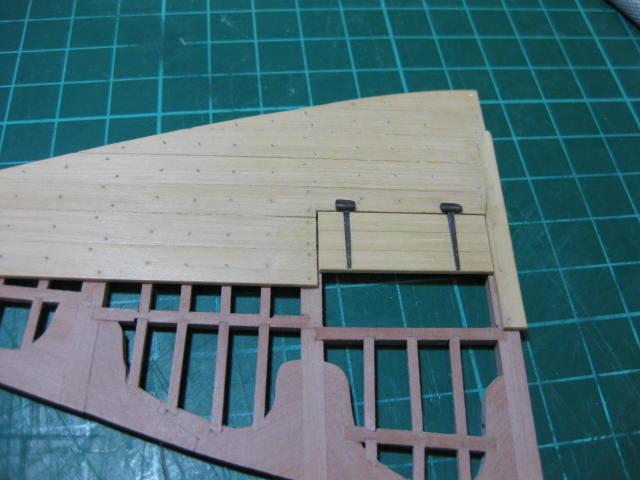
An Edging piece finishes the fore edge of the platform. The Spirit Room (or Fish Room) hatch has been fitted to the port side, and one brass hinge has been placed into position for the purposes of this picture :
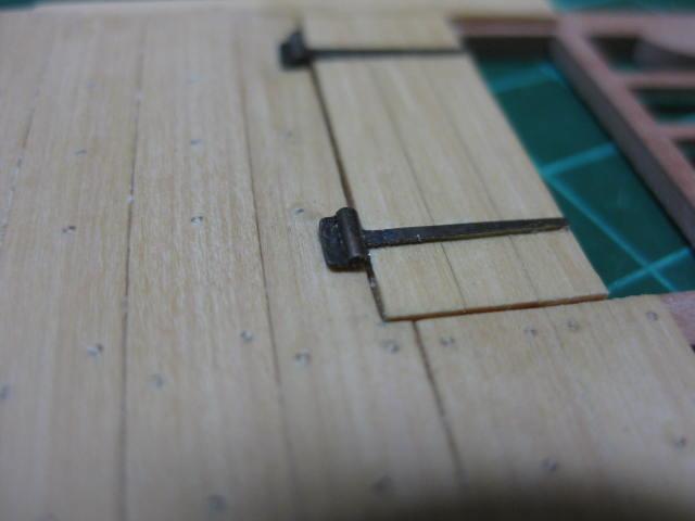
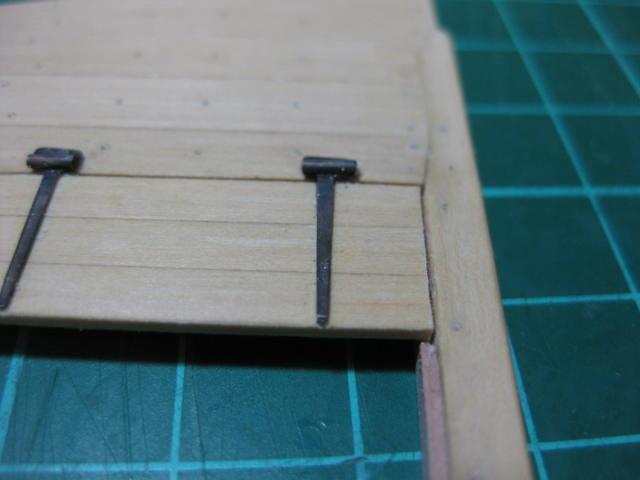
The hinges were made from brass sheet, filed to shape, a small "pin" soldered to the top and finally blackened before being epoxied on :


HMS Vulture 1776 by Dan Vadas - FINISHED - 1:48 scale - 16-gun Swan-class sloop from TFFM plans
in - Build logs for subjects built 1751 - 1800
Posted
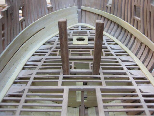
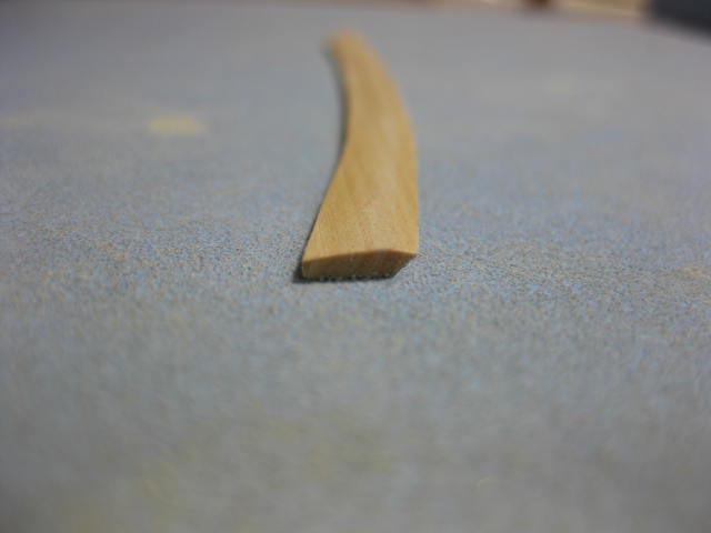
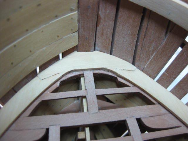
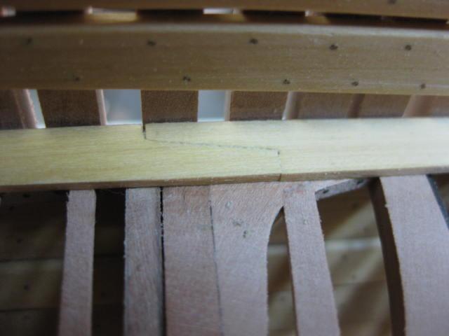
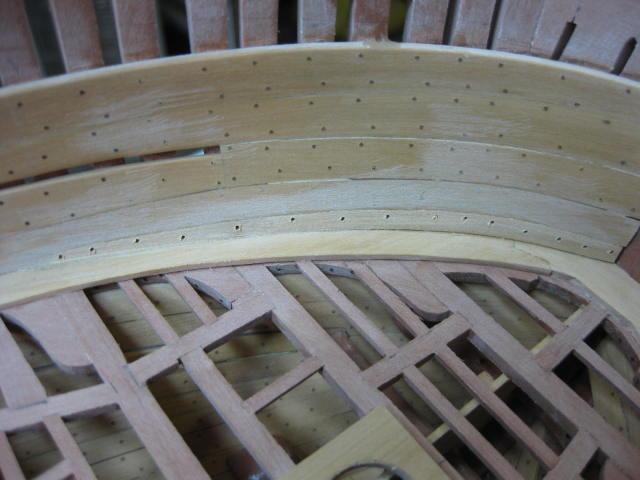
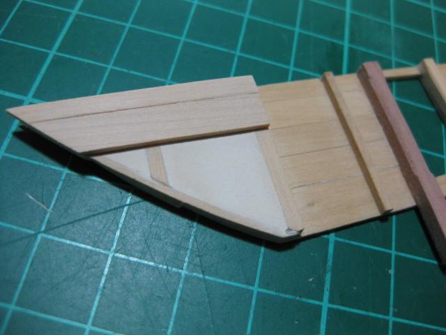
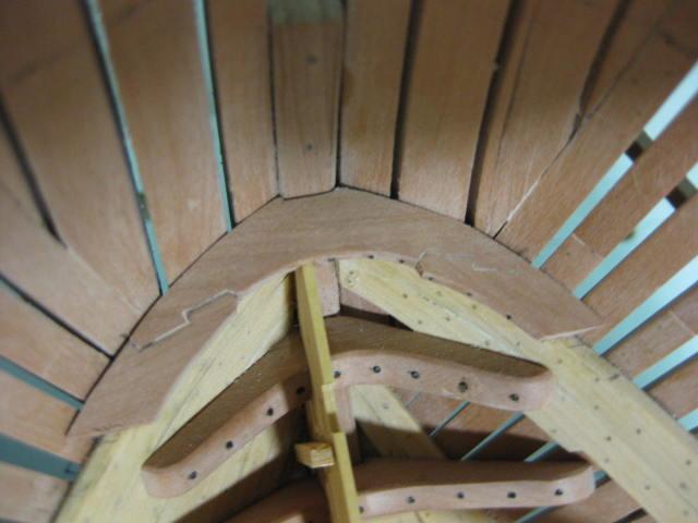
Lower Deck Breasthook
This is made in similar fashion to the previous Breasthooks. It is made from 8" stock.
A lot of "repeat" work happens during the course of building a model, with only minor variations in the dimensions of the timbers used (also known as Scantlings). Where this happens from here on I'll let the pictures tell the story rather than repeating myself, with only significant changes noted.