


Dan Vadas
-
Posts
3,261 -
Joined
-
Last visited
Content Type
Profiles
Forums
Gallery
Events
Posts posted by Dan Vadas
-
-
Thanks again to Wayne, David, Druxey, Guillermo, Michael, Adeline, Randy, Sinan, Mark, Mark and Shaz - your comments are always welcome and appreciated
 .
.was there actually enough space between the pumps so that both could be operated at the same time? The pump crews must have been facing each other obviously
You answered your own question Adeline - the crews WERE facing each other. There is about one foot of clearance (real) between the cranks when they are closest together. I have no doubt there would have been considerable competition between the two crews
 .
.How small or big are those things, anyway?
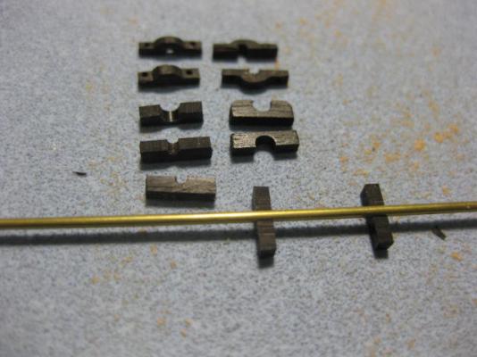
SMALL Mark - the bearings on top of the cisterns are 4.5mm long, 3mm high and only 1mm thick. The rhodings themselves are 2mm OD round bar which has been drilled to take the 1mm diameter cranks.
I cannot fathom how this can be done from scratch and come out looking so beautiful!
It's actually easier (for me) to make them from scratch instead of trying to modify a shoddily made Kit part
. Danny
Danny -
Welcome back Frank.
Sorry I haven't been on your Build log for a LONG time - I've been a little bit busy since the Great Crash
.I'm fairly pleased with the way the sails came out, considering everything was done by eye.
 at least they add a little character to the ship !!
Your ship has more character than most others I've seen, and those excellent furled sails certainly help. Great Job mate
. Danny -
If a Builder DOESN'T want someone else's photos in their Build log but someone puts one (or more) in anyway - contact a Moderator via PM and they can be removed.
If someone posts pics on another's Build Log - and the author of the Build Log has already said he doesn't want any one else's pics - then the offender will be dealt with as we see fit.
Danny -
Thanks Remco, David, Alex, Allan, Grant, Joe and Sjors
.A good test in patience and determination. How many were scrapped before you were able to get them perfect?
David B
None actually - I made a couple of spares, but didn't need them
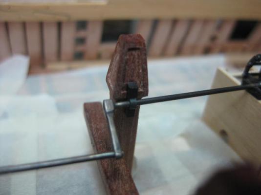
. The Rhodings are a PERFECT fit into the spacers - they need a gentle push to get them in but stay there by themselves. This makes assembly of all the pieces a fairly easy task - well, relatively easy  .
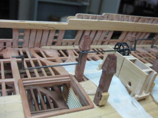
.Here are a few pics of my current progress - aligning the Rhodings, Bearings and Sprocket has taken some time but I'm getting there. I've had to remove and re-glue a couple of the Rhodings, and I still need to raise the forward starboard one a touch to get it to sit perfectly.

 Danny
Danny -
Hi Grant,
Sorry it's taken so long to catch up with your Build - I haven't had a lot of time lately (matter of fact I've only just started back on "Vulture" in the last week or so).
When I built my Victory I knocked off halfway through tying ratlines - and didn't resume for 10 YEARS. There sure WERE a lot of them
.She's looking good mate
. Danny -
Thank you very much Dave and Dave
.I would probably dribble all over your model
You do and you'll clean it up
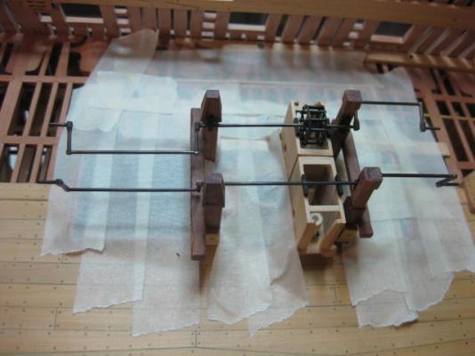
. Seriously, if you're ever up this way - drop in. You're more than welcome.Rhodings
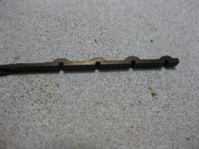
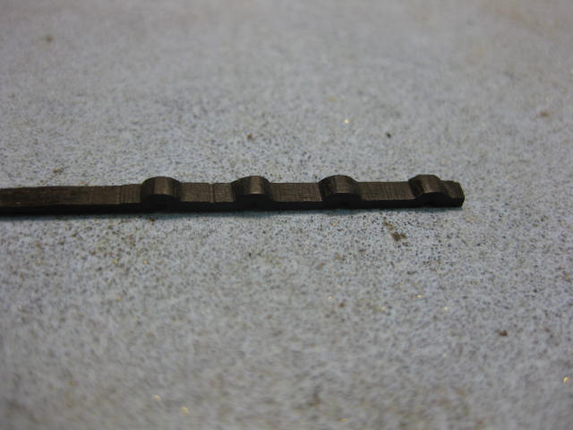
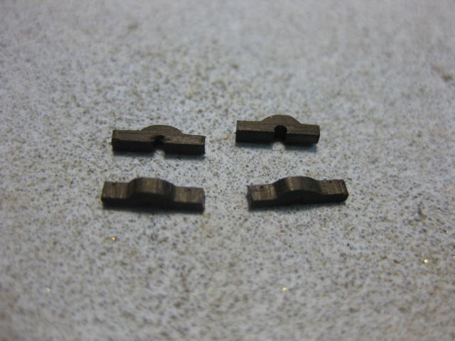
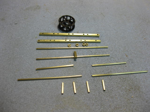
I've made all the Rhoding Spacers and Bearings for the pump brakes. I used Ebony - I didn't have any suitable brass, and besides it's a bit easier to do with wood (yes, even Ebony
). There are several slight differences in some of the spacers to make up for the differences in the sizes of the Bitt Pins - everything must line up straight .... no easy task  .
.
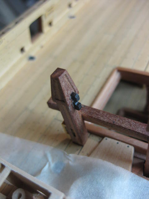
One Rhoding Spacer glued into place :
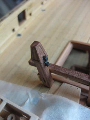
I've also turned up two Pillars which support the aft ends of the pump brakes :
 Danny
Danny -
-
Thanks Greg, Pat, Janos and John.
I'll bet the wheel turns when you rotate the crank.
Greg, they'll both turn before I add the chain to the starboard side - as it doesn't go all the way around that side will have to remain static.
Janos, that's exactly my method too
.And yes, I'll be painting them with satin poly. Danny -
Thank you for the information on places in Oz for brass Janos - I was already aware of them personally (my local Model Railroad shop ... "Vic Barnes Cycles and Model Railroad" in Newcastle also has an extensive range of brass stock - convenient for me
). Guillermo is in the US, so I gave him somewhere more "local" to look at.Thanks for taking the time to go through my somewhat truncated "new" Build Log Adrieke
.and getting to know that each plank and part has its own name
It's important to know the correct terminology for the parts of a ship, especially when it comes to doing Research etc for a scratchbuild (or even a Kit - some kit manufacturers use completely WRONG terminology which adds to the confusion of anyone relatively new to model ship building
 ).
).Hi all,
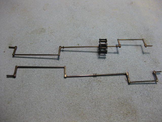
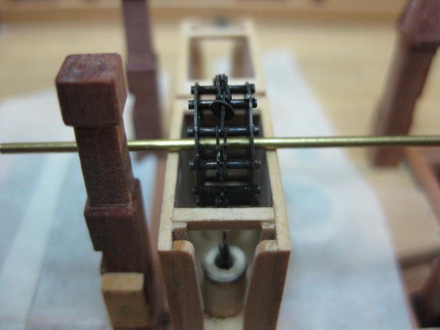
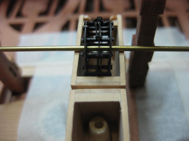
I've finished making the Pump Brakes - only 8 Bearings and Rhodings to go. The pics show them in various stages of construction.
I used Birchwood-Casey Brass Black to give them a LIGHT coat of black - I like the effect of the lighter color, it shows a lot more highlights (the pics don't do it much justice - they look a lot better in real life, and I'm stoked with the way they turned out
).
Cleaned up ready for Blackening :

After Blackening and polishing :

One brake "in place" for the camera - the bearings haven't been made yet :
 Danny
Danny -
Thanks for looking in John, Druxey, Guillermo and Pat - your comments are much appreciated.
Could you suggest best sources for brass materials?
I get mine from a local Model Railroad store, but I see that Model Expo have a nice little package of various shapes and sizes - check this link :
Another good site is JBModel - they carry VERY small diameter brass tubing etc.
Danny -
-
Thank you David and Grant.
Lovely work on the Cisterns Remco
. Grant, that's the same excuse I'm using .Pump Brakes
Hi all,
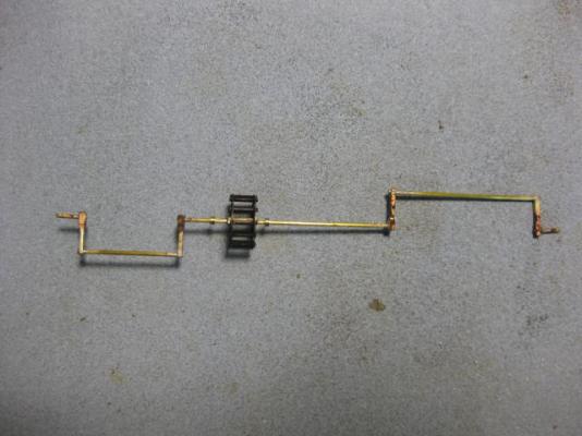
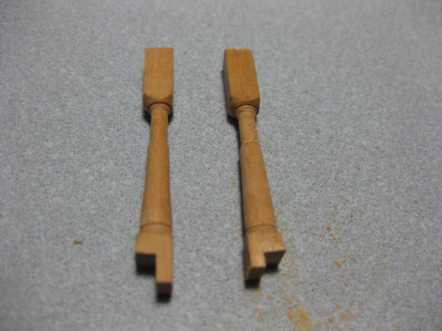
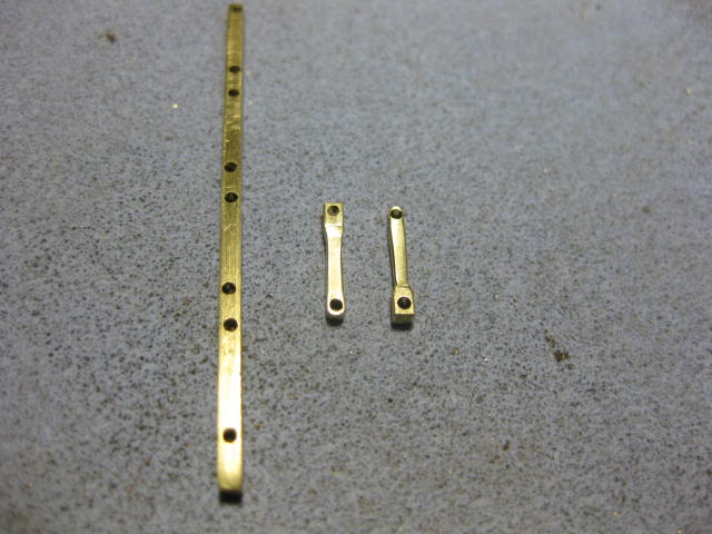
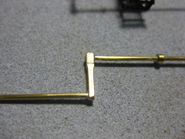
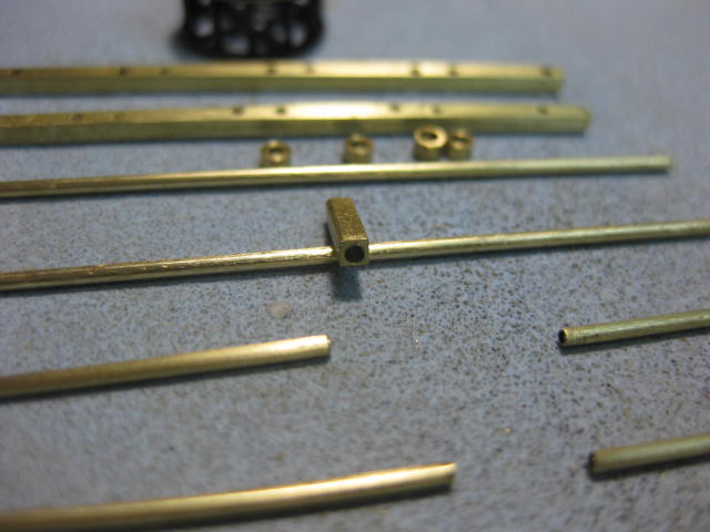
Work begins on the Pump Brakes (or Cranks). I've drilled all the holes for the brakes to accept the shafts - I drilled them all in two longer pieces which will be cut to length after I've done a bit of filing to get their correct shape. It's a lot easier to do them this way - saves a lot of setting up, first in the Mill for the drilling, and then in the vise to file them.
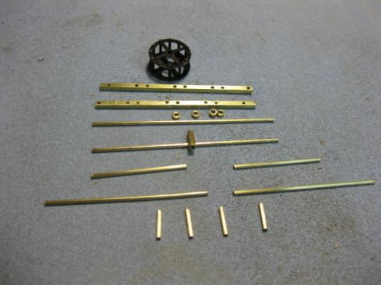

I've also cut all the various lengths of Axletrees (shafts) - these are all a little overlength, they will be filed back after silver soldering the two pieces together. The single square piece is for the sprocket centre - this has a 1mm hole drilled through it's 8mm length for the shaft. It's a little too thick - I'll get it to the right size after I've soldered it to the shaft. It has a wall thickness of 0.3mm across the flats at the moment, which will be reduced to 0.1mm - a very difficult task to drill if I'd reduced the outside dimensions first
. Danny -
Hi Amfibius,
From my last few builds, the tools I need most are something to sand the hull after planking, because doing it with a sanding block is a massive pain. I also need something to help shape the planks precisely before they are installed. I am getting better at planking, but I still use too much wood filler for my liking.
One goes with the other - as you get better at shaping planks (and there is no power tool that will do it for you any easier than you can do with a sanding block) you'll find the hull becomes much easier to sand by hand.
For the time being, use a heavy grit paper (80 is about the best) for your initial "rough" sand and finish it off with lighter grits to 240 grit. If you Contact Cement the paper to a cork block it makes it a lot easier too. Buy an extra cork block and shape a "half-round" into it to do inside curves.
Replacing the paper is easy if you have a heat gun - a hair drier on max power would do the job of softening the glue but it may take a while.
Final sanding should be done without a block - use 400 grit held in the palm of your hand.
Danny -
Good trick on the Hanging Knee template Toni
.Of course, now that I have the hang of things, I am finished with the hanging knees on the lower deck.
Ah, but the trick will come in very handy for the Upper Deck, Quarterdeck and Forecastle knees
. Danny -
Hi again Adrieke,
Found it - "The Railcar" at Corlette, about half an hour north of Newcastle. They list the Chopper II at $69.95. Here's the link to their web page : The Railcar
Danny -
Adrieke, you may have to get one on-line - here's one link : Chopper II
I'll see if I can find the site for the shop I bought mine from (it was a while ago), but I know I paid more than $64 for it - more like $85 - but it's a better tool than the one Modeller's Shipyard sells. The Chopper has a "self-healing" cutting mat and is a fair bit wider.
Danny -
Hi Jay,
Dan, have another look at the picture I posted just before you said this. Besides, my little formula is simpler than yours because I added the 7 to the division of 13 by 16. Then the whole thing is multiplied by my favorite number 25.4.
It depends on the way you punch the numbers into the calculator. If you do it the exact way you wrote the formula you get 31.75. However, if you do it like this : (13/16)+7x25.4 you get 198.4375, which is correct.
Your original formula was the same as (20/16)x25.4 .... or in other words 1.25x25.4. The fraction needs to be divided before the number of full inches is added.
I'll leave this alone now - the point I'm making is that Conversion Charts are NOT "Useless Tools" because they avoid errors like the above (as long as you can find the chart
). Danny -
Eagerly awaiting your progress
Thanks John, I'm hoping to get a few days in before I have to disappear again for the weekend's work on my holiday van - which is getting very close to completed
. Next job on it is building a workbench for my ship modelling .I look at scratch builds yours in particular and think how can he do something so neat and perfect
Derek, you're far too kind
. Like most of the guys and gals here I started on Kits (I built about 10 before I started any Scratchbuilding). Most of that phase was foundering in the dark using the kit's instructions, with no real idea of how to do things properly - you know the story .Then I connected to the Internet and found a great Site of "like-minded" people who helped me out enormously .... yep, MSW. This changed the whole perspective of how I viewed building my models - from religiously following Kit Instructions with all their errors and omissions to "getting it right" ... at least as far as every avenue of research permits (and there are a LOT more of them than you may imagine).
Couple that with a half a lifetime's worth of acquiring some great tools - some more useful than others - and here I am
.Honestly - anyone can do work like this if they have the passion for it, are willing to accept advice from more knowledgeable people, and have the desire to improve their skills with every step they take.
Wow, for a bit there I thought you were going to try to make a working pump.
I don't think we've seen the saucers added before on any build.Mark - wait until Remco gets to this stage .... I reckon he'll have a go at actually making it work
. I think EdT actually DID . Danny -
Hi all, and Pat in particular -
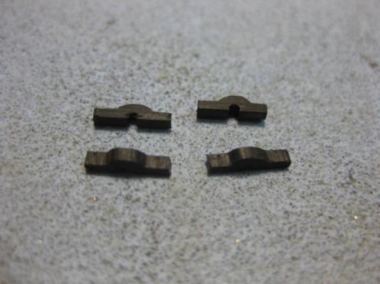
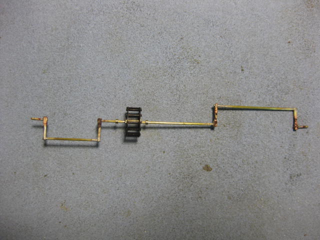
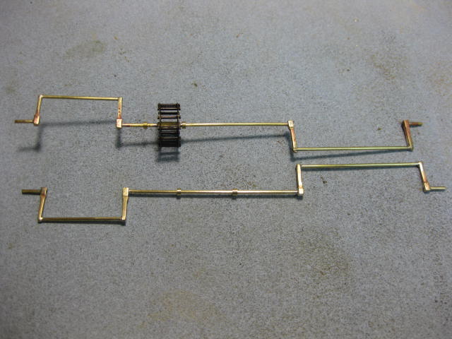
Here's the Chain "in-situ". This is only a very rough Dry Fit to see if I have enough chain to do the full circuit .... I don't have quite enough, two more links will be needed to make it disappear into the Tubes. I'll add two more Saucers as well - these can be epoxied inside the tubes to properly finish off both ends. The Rhodings at the top of the Cisterns will bring the chain and sprocket up a little, and the shaft is simply a piece of wire so far - it needs a LOT more work before it's finished :


I used Masking Tape on the open deck around the cisterns to prevent any mishaps like dropping the chain into the hold
. Danny -
I thought you were a scratch builder!
John
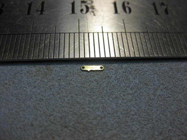
John, what else can I say to that than
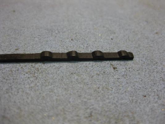
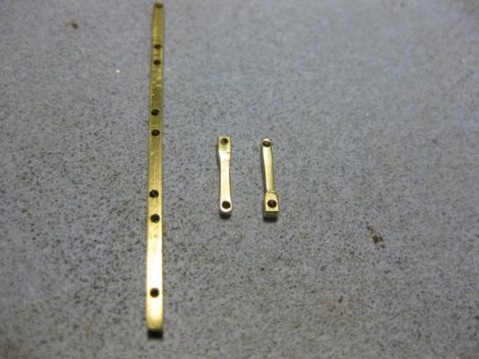
:D ? The individual Links are 4.5mm long, 1mm wide and 0.15mm thick. They have a "tooth" on one edge to pick up the chain and two 0.5mm holes for the pins. PE is by far the best option to make 26 of them EXACTLY THE SAME - as I may have mentioned, I only have ONE lifetime in which to finish this model . Here's a pic of one of the 26 links :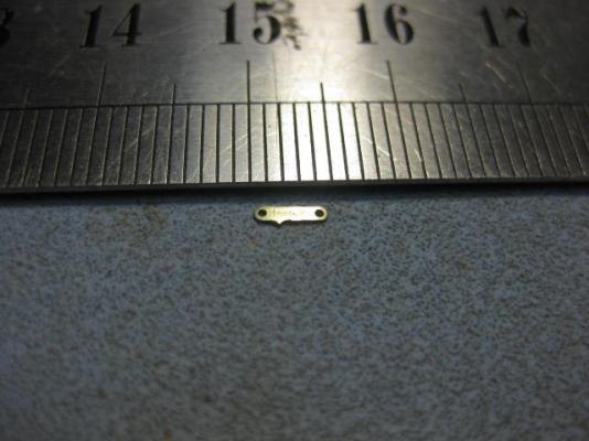
Wayne, Pat (look for an update on the chain very shortly), Adam, Grant, Christian, Dick (I forgot about the key
 , I might do one for the Captain's Cabin instead ), Greg and Aldo - Thanks heaps for the compliments . Danny
 -
Well done on the intake Toni
.I suggest you make a "dummy" for the other side so the tube has something to sit in - just a piece of timber with the appropriate size hole will do the trick.
Danny -
but balsa is easily processed and well holds a form
There are plusses and minusses with many techniques - find the one that suits you best by experimenting with several methods.
Danny -
hmm that choppper II or the copper III seems a good choice. lets see if its available in oz
Sure is - I got mine from a Model Railroad shop north of Newcastle, but some of the others in Sydney or Modeller's Shipyard at Blaxland in the Blue Mountains probably carry them or can order one in for you.
Danny -
Hi Crackers,
You're not contradicting me - I used to use balsa for Fillers :
Balsa being soft, accepted the pins manually pushed into place.
The problem is the softness of the Balsa - pins don't always hold in it as well as they do in a harder wood, which is what I now use (actually I now use planking SCREWS instead of Pins).
Danny


HMS Vulture 1776 by Dan Vadas - FINISHED - 1:48 scale - 16-gun Swan-class sloop from TFFM plans
in - Build logs for subjects built 1751 - 1800
Posted
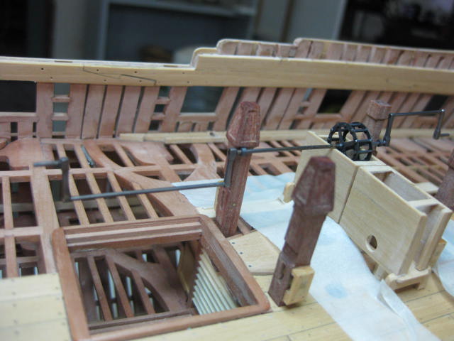
Forward Stanchions, Cistern Hood and Pump Dale
Hi all,
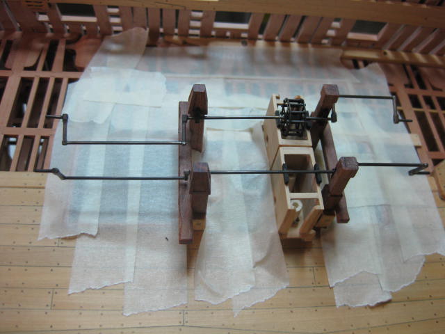
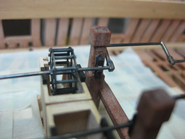
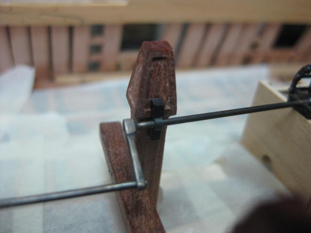
The last few things for the Pump Assemblies (almost) - I've made the Forward support Stanchions, the port side Cistern Hood and the Pump Dale for the same side. None will be fitted to the starboard side.
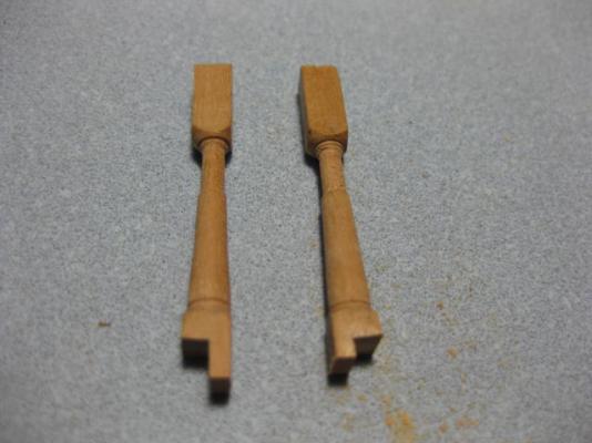
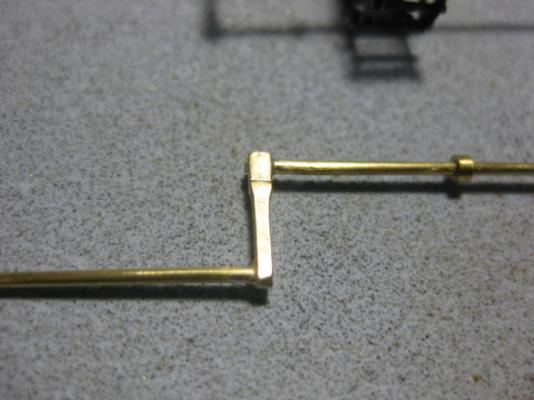
The Stanchions support the forward ends of the Cranks :
The Cistern Hood is made from 1mm thick side pieces and 0.35mm boards over the top :
The Pump Dale is a removable item on the real ship - it would be a constant trip hazard otherwise. It is made from four pieces of 0.5mm thick timber, and attaches to the cistern via a board which can be lifted upwards :