HOLIDAY DONATION DRIVE - SUPPORT MSW - DO YOUR PART TO KEEP THIS GREAT FORUM GOING! (Only 20 donations so far - C'mon guys!)
×


Jared
-
Posts
305 -
Joined
-
Last visited
Content Type
Profiles
Forums
Gallery
Events
Everything posted by Jared
-
The discussion on the previous page of this build log of the FF's bow / forcastle has been quite facinating and the research has been quite thoughtfull and eye opening. Thanks to all of the contributors!
-
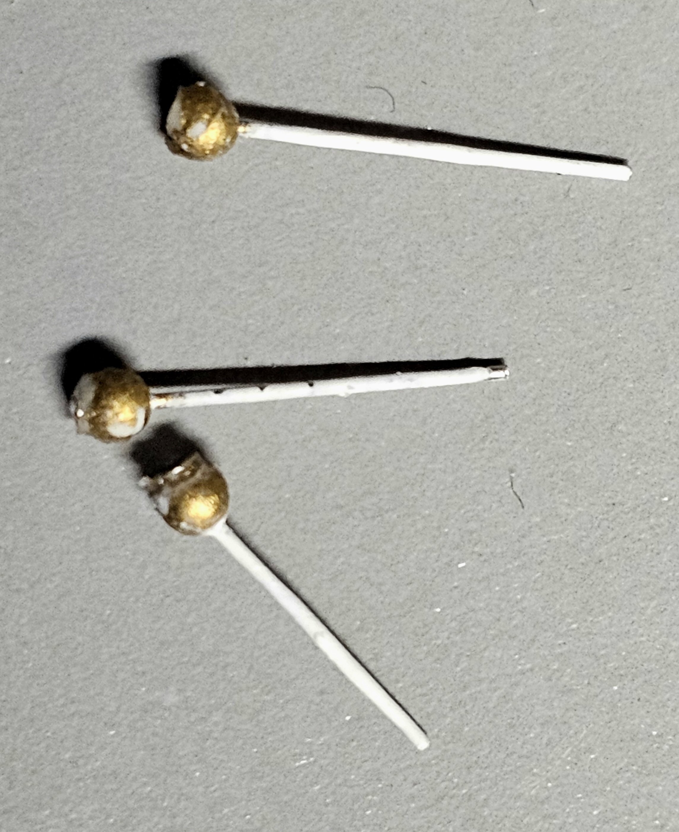
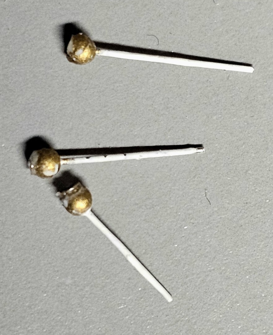
Thanks. Attached is a photo of my lightning rods.
-
Nice craftmanship. For the lightning rods at the tops of the masts, I used the pins that come with new shirts. I painted the plastic ball part with a metalic paint and cut the metal pin part to the desired length. I glued the ball to the top of the mast with super glue. I used a small drill to create a bit of depression at the top of the wood mast to provide a better seat for the ball. I recently remade all of my topgallant masts out of a stronger wood than the kit's basswood due the breakage problems. I have decided not to add the lightning to the mast tops until the rigging is complete, to minimize risking knocking them off (again).
-
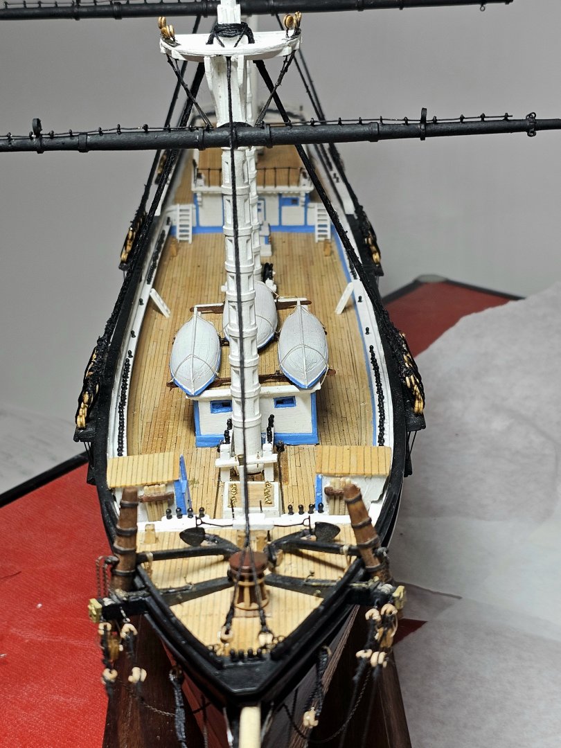
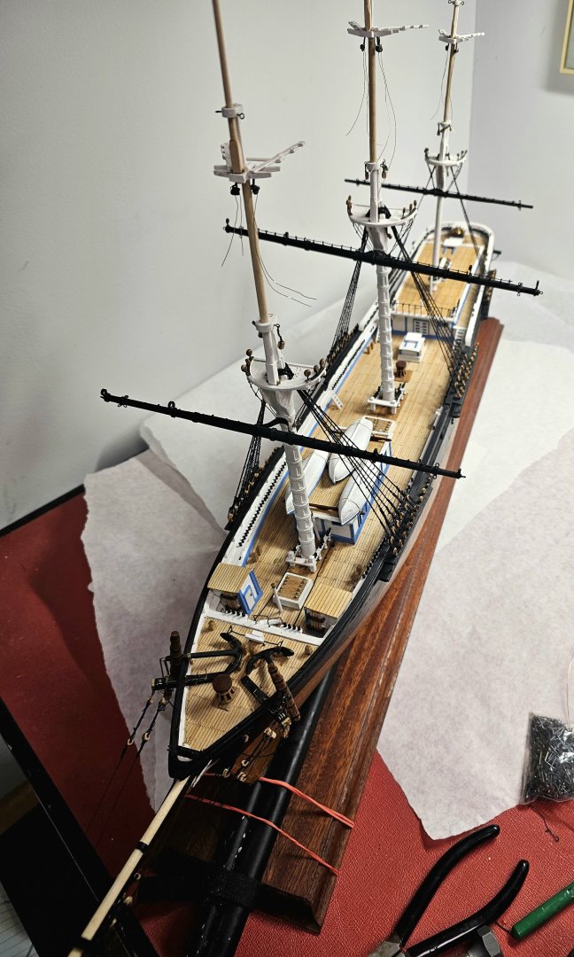
Just completed rigging of the shrouds on the fore top mast section. It had to be completely handmade on the ship, as the lower and topmasts had already been glued in place. Having done this, I can more fully appreciate Rob's method of rigging the masts off-model. I can't begin to describe how many times I bumped into the fore lower yard while tying the lanyards and ratlines. The lower yard lifts, which had already been rigged, also got in the way. However, after 2 challenging days, I got it all done.
- 431 replies
-
- 2
-

-
- Flying Fish
- Model Shipways
- (and 2 more)
-
Thanks Rick and ClipperFan. I intend on making the gaffs and all of the other thin spars using the hardwood dowels. Fortunately only a relatively small diameter the lower diameter spars have been made so far from the basswood so not a lot to remake.
- 431 replies
-
- 1
-
-
- Flying Fish
- Model Shipways
- (and 2 more)
-
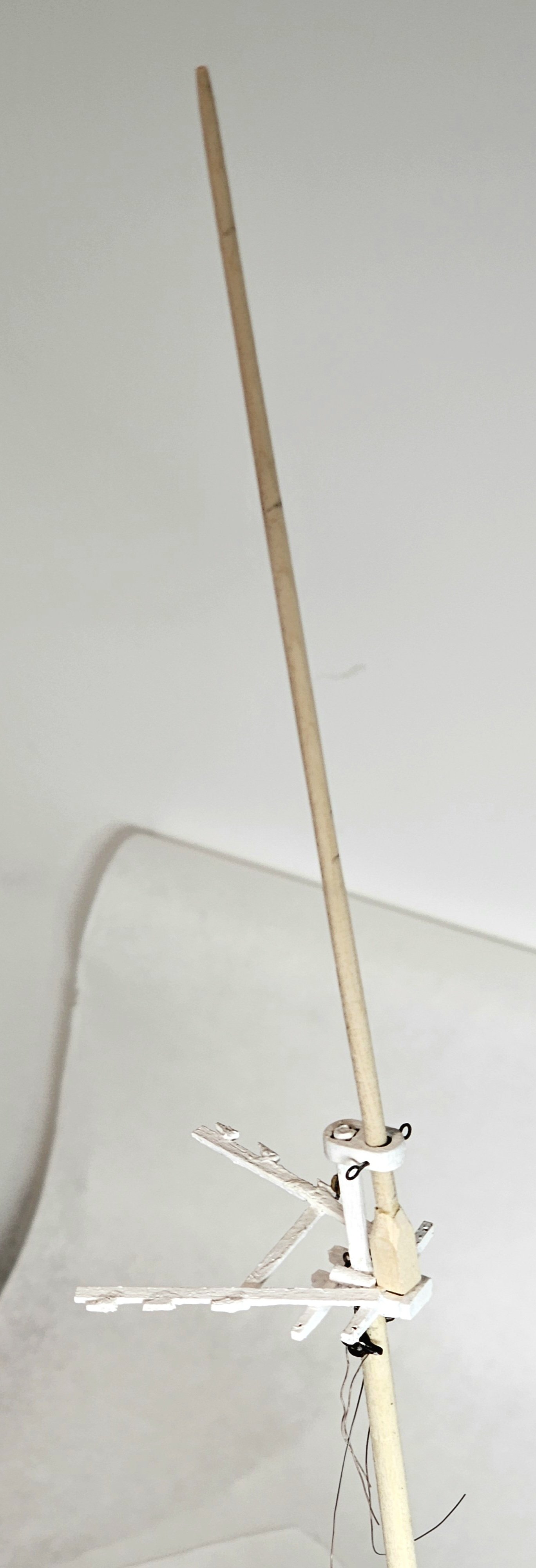
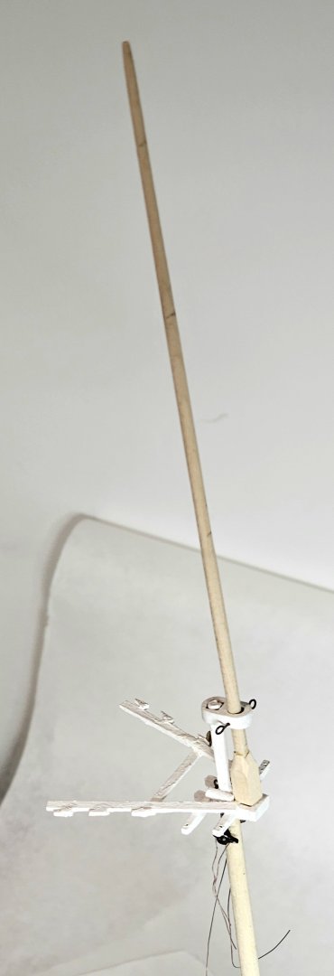
Back at it again. I found a speciality wood store that had a variery of hardwood dowels of diameters 1/8", 3/16", 1/4 and up. They were labelled birch or maple. I was easily able to remake my 3 topgallant masts by turning these on a drill and sanding away carefully and using calipers. I glued strips of basswood to the base of each mast and sanded them to the required shape, as shown in the photo (the new fore topgallant mast) I not added the fids or top lightning rods yet.
- 431 replies
-
- 2
-
-
- Flying Fish
- Model Shipways
- (and 2 more)
-
Congratulation on your retirement Rick. Welcome to the life of leisurology. I look forward to seeing your continuing progress on your beautifully built Flying Fish.
-
Thanks for your suggestions ClipperFan. The recent break occurred to the mast as I was rigging it off the ship, trying Rob's approach. I think my only option if the problem continues is to bite the bullet and remake all of the thinner spars using a stronger wood like boxwood or degamme.
-
Thanks ClipperFan. For now I have used super glue for the repair. On another similar tip break of the jibboom superglue wasn't enough and I had to resort t epoxy which so far is doing well. In both cases the breaks occurred in a thin area where there was a drilled hold for rigging. If I could of I would have drilled into the wood on both sides of the break and inserted a steel pin as an internal splint. I can tell you that it took hardly any force to cause these breaks. I am going to try applying superglue around other fragile mast sections to strength. them in hopes of preventing such problems as I go forth.
- 431 replies
-
- 1
-
-
- Flying Fish
- Model Shipways
- (and 2 more)
-
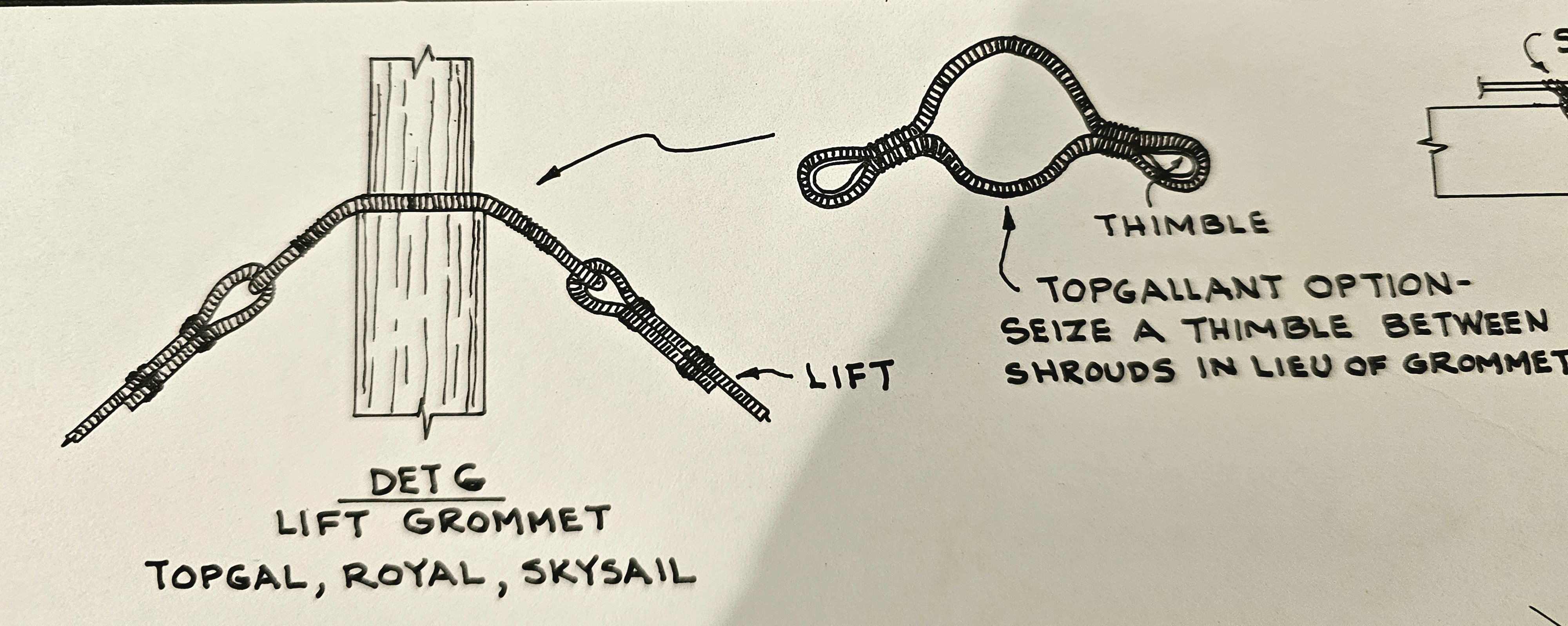
After spending a week tracing the various standing and running rigging lines I am back at rigging again. I am going to adapt Rob's approach of rigging the masts and yards off the model as best I can, as all the lower masts are already glued in place as is the fore top mast. I spent much of today agonizing over how to build the lift grommet for the fore skysail yard. The first figure shows it is made of siezed rope with a thimble in each side loop. The line is 2" rope, which at scale equates to 0.007" dia. thread. I knew there was no way I would be able to produce it from thread. After a lot of thought I came up with another approach using thin black wire for the rope part and thimbles made from a thin narrow strip of brass. The sequence and final result is shown in the photos. I have one major criticism about this model kit abd it is the choice of fragile basswood for the masts. As I was assembling the grommet on the thin mast the mast broke in my hand at a point where a hole had been drilled for the shysail hailiard. I have glued it back together but still need to do more work on it to make the repair look better.

-
If you expand the photo I attached, you will see someone tried to repair part of the sail using a mesh fiber tape. There is also damage on other sails, with some small pieces of sail broken off. She is in discussion with a tall ship builder regarding repairing some of the rigging that has become loose. As I recall from one of the Revell tall ships I built when I was a kid, the plastic sails were supplied in the kit.
- 431 replies
-
- 1
-
-
- Flying Fish
- Model Shipways
- (and 2 more)
-
I have a friend who inherited a fully rigged Revell plastic model of the USS Constitution from her father. The model, made many years ago had been fitted with the kit's plastic sails. Over the tears the sails turned yellowish and became brittle and broken. A photo is attached. I suspect sunlight exposure was consequential here.
-
Will plastic block affect the lifespan of the model? Will they become brittle with time (20 years)? I have read about plastic models deteriorating with age, especially if exposed to direct sunlight.
-
Thank Rob. I knew that the lower fore yard lift was going to be even more difficult if I tried installing it after the main stay. That us why I installed and rigged the lower fore yard and the lifts when I did. I am going to take a bit of a pause and think out the remaining rigging sequence to completion more carefully. I will also consider your yard pre-rigging suggestion. Thank you.
-
The 2 things I fear most is pulling out a lift eyebolt and snapping off (again) the end tip of the bowsprit. That is why you can see a pair of thick dowels "guards" extending from the base of my model at the bow.
-
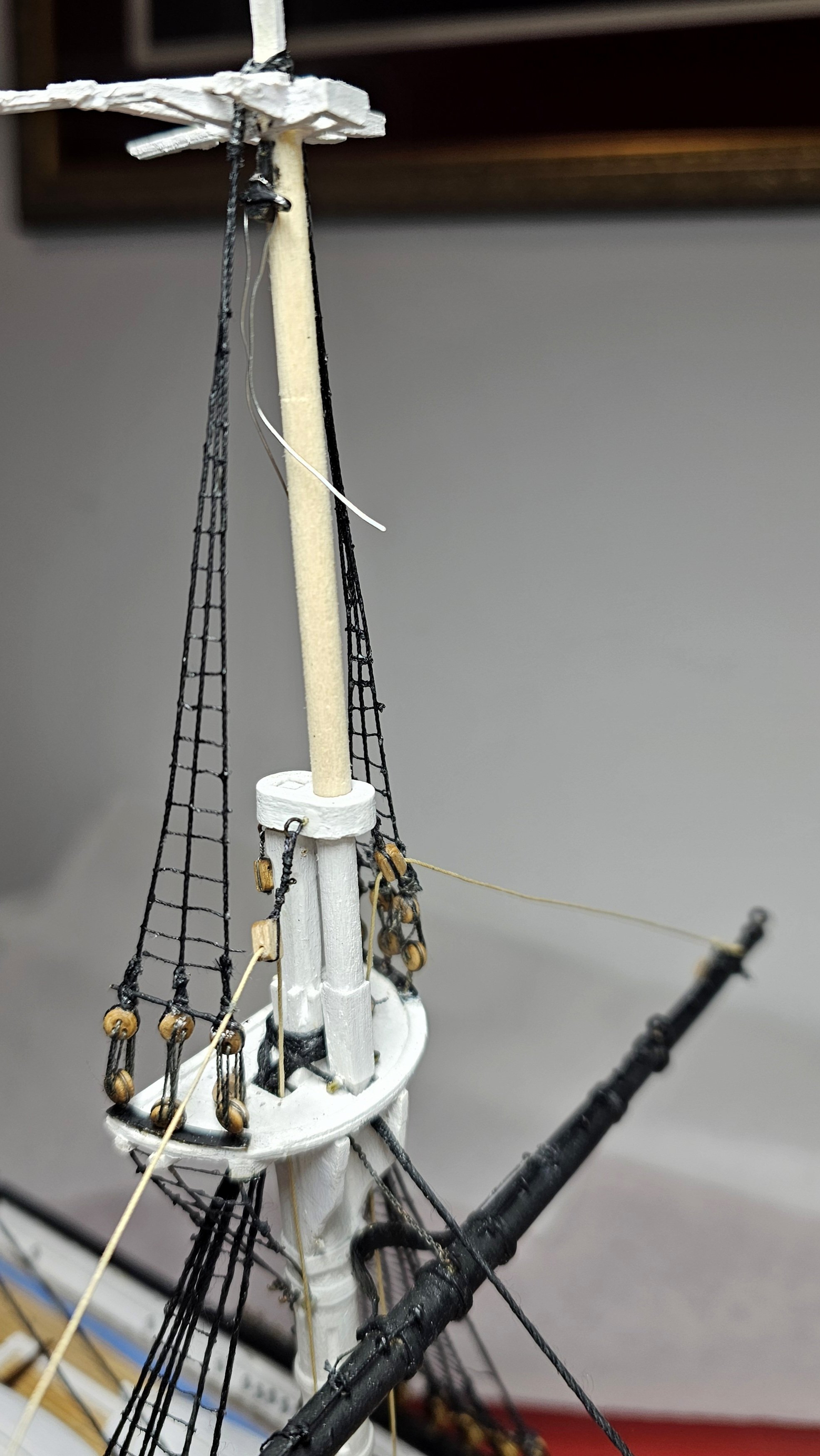
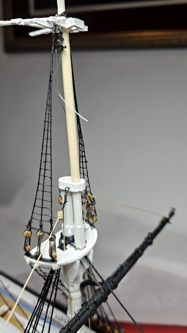
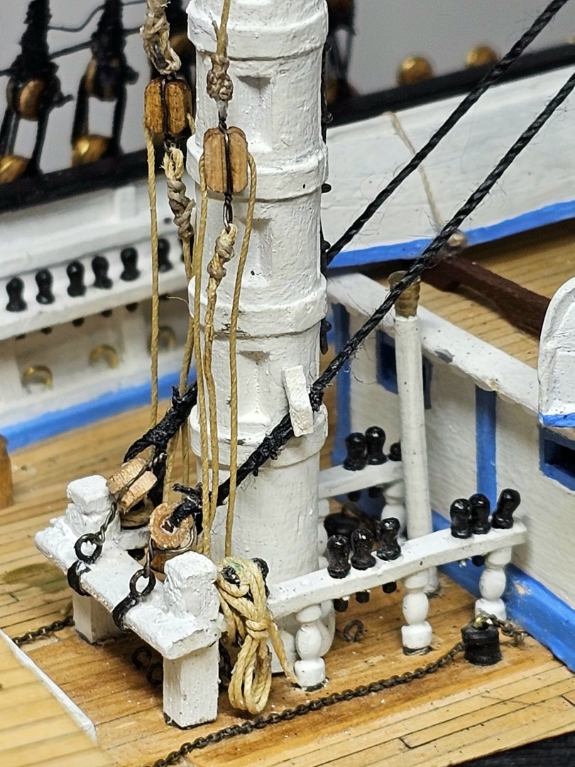
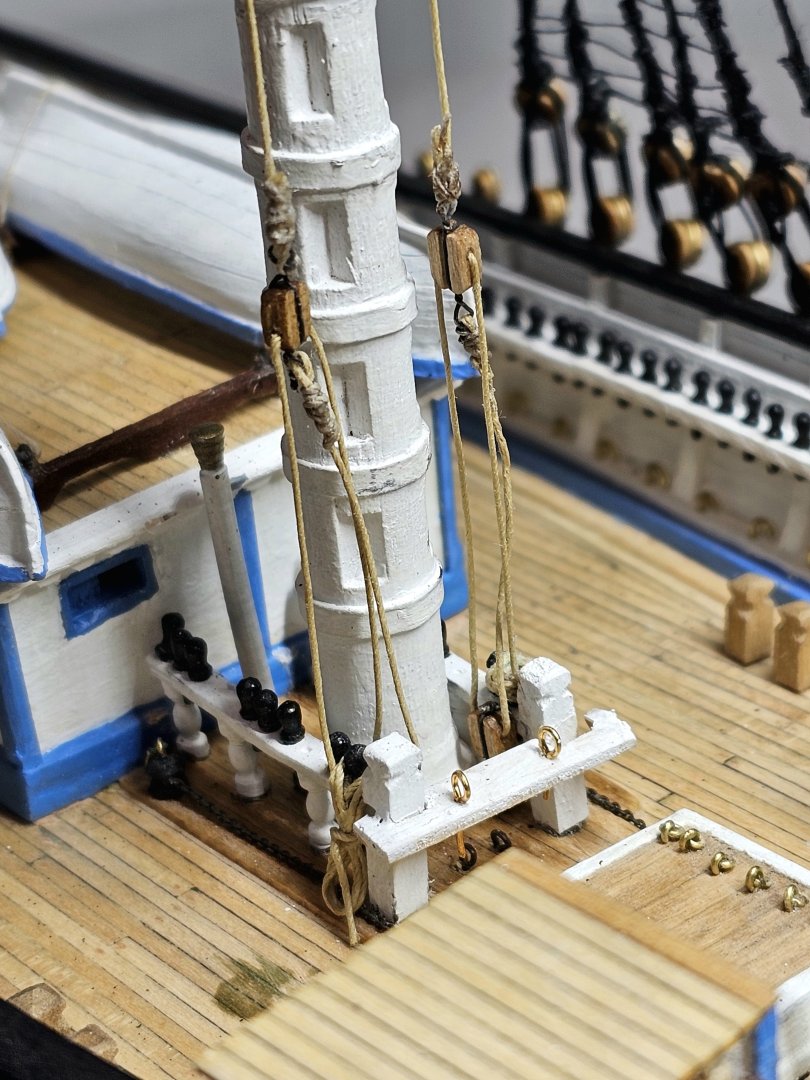
Thanks Rob. Your rigging work is impeccable. I had to learn much of what you recommended the hard way! And it was painful in many ways. When I started the lifts I quickly realized it would be impossible to rig the lower blocks to the eyebolts that were already secured under the fife bar. The only feasible option I could think of was to pull out the eyebolts, then attach a lower block, rig the upper block (see photo) and then, with great difficulty, reglue the eyebolt (assembly) back in place. 🤬 As to the rest of the running rigging, my current plan is to I limit this to the yard braces, halliards, downhauls, lifts and vangs.

-
Thanks to both of you for sharing your rigging knowledge. To clarify, the rigging sizes I have been using have been as per the kit's plans. All rigging threads supplied in the kit or purchased as additional sizes from Model Expo were double checked for size by myself using a microscope with a micrometer. The particular tan thread I used for the 5" lift line was made by Mantua. It is free of fuzz but is relatively stiff (feels like it has been starched). This makes it harder to tighten, especially around sharp bends. I had to be extremely carefully during tightening not to pull out the eyebolts secured to the deck under the fife rail. For the remaining lower yard lifts I will have to use the same line to preserve a uniform look. The upper lifts are of smaller diameters so they should be much easier to work with. Thanks as always for your feedback and encouragement. Much appreciated.
-
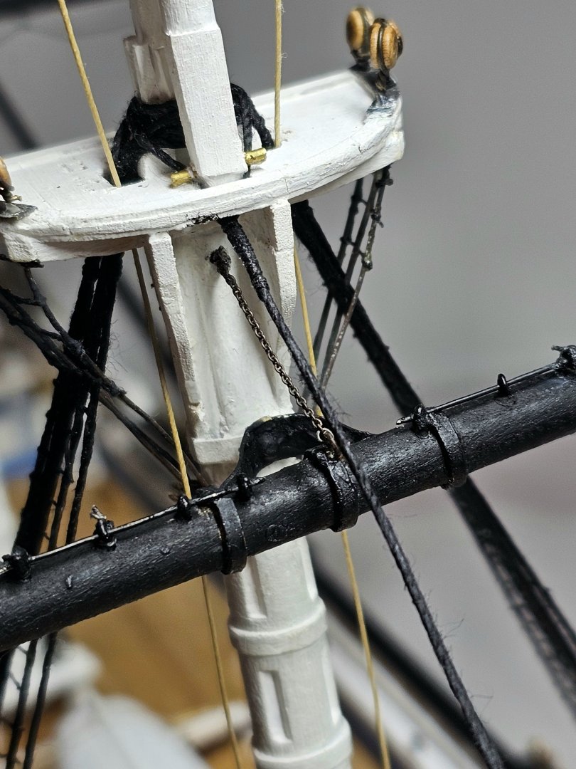
I tried tightening the port side lift. It's about as far as I can go. I then fitted the main stay which included rigging through bullseyes and making 2 tiny cleats on the fore mast.
- 431 replies
-
- 3
-
-
- Flying Fish
- Model Shipways
- (and 2 more)
-
Your build is coming along very nicely. Interesting historic account if the launch, especially the style of the writing.
-
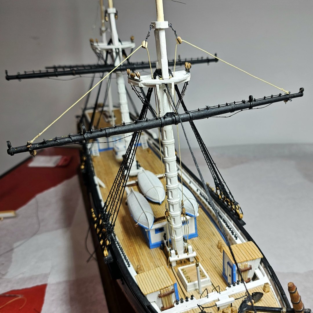
Over the last 3 days I have mounted the lower yard on the foremast, together with the chain sling and the fore lifts. I can't even begin to describe had difficult the lifts were to make and rig, given how tight the working space at the fife bar. I am off for celebratory scotch! At this time I am not planning to rig any cluelines.
- 431 replies
-
- 2
-
-
- Flying Fish
- Model Shipways
- (and 2 more)
-
As I work through the rigging on my FF I have really come to appreciate your build log and the great skill of your work George.
-
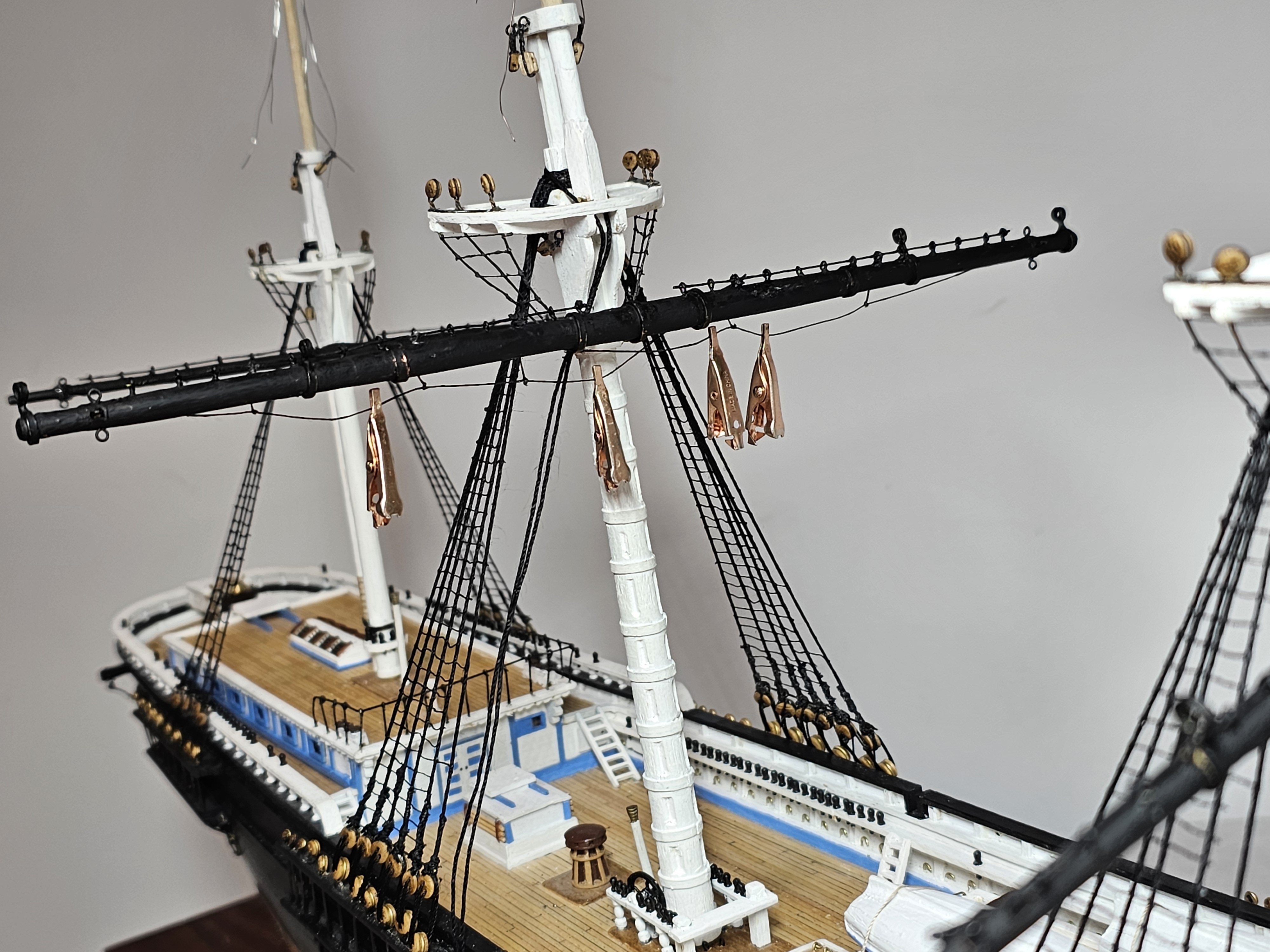
Completed the footropes on lower fore and main yards. To get them to hang properly I treated them with diluted white glue and weighed them down with small copper clips. A light coat of black paint was also applied.

- 431 replies
-
- 2
-
-
- Flying Fish
- Model Shipways
- (and 2 more)
-
Today I tackled the lower forestay, which was a bit of tricky work involving rigging through bullseyes in a tight space and siezing the rope.
- 431 replies
-
- 3
-
-
- Flying Fish
- Model Shipways
- (and 2 more)
-
Have now finished the lower yard on the mizzen mast. It turned out to be an exercise in frustration. The choice of using basswood in the kit for the yards was a bad one IMHO. The narrower yards become quite fragile especially near their ends, once the various holes are drilled. My mizzen lower yard broke about 1/3" from one end, where I had drilled 2 perpendicular holes for 4 eyebolts. I twice tried gluing the broken end back on using a combination of super glue and yellow wood glue, but it kept breaking off. The third time I went to epoxy glue and this seems to have worked.
- 431 replies
-
- 3
-
-
- Flying Fish
- Model Shipways
- (and 2 more)