allanyed
-
Posts
8,149 -
Joined
-
Last visited
Content Type
Profiles
Forums
Gallery
Events
Everything posted by allanyed
-
 Hello Baris, Properly spiled planks can be soaked and pre-bent and dried before gluing to the model. If this is done, they can be held with the fingers for a minute or less while the glues starts to set.(aliphatic glue). There is no need for pinning. That said, making perfectly spiled planks is not always possible if only using strips of wood such as come in kits rather than cutting from sheet stock as mentioned by Chuck. A number of planking clamp designs have been shown on this site including many by Ed Tosti in his Naiad build log (and books.) They eliminate the need for using pins. Allan
 -
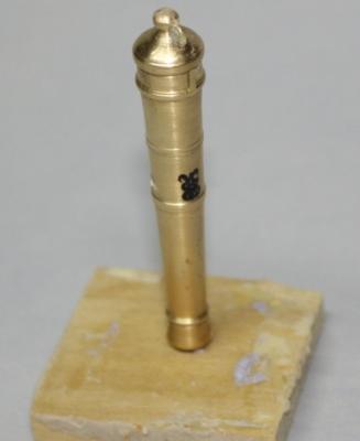
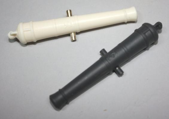
Philo, Take a look at the www.vasamuseet.se site and go to the "Creating the Cannon" section. You may find it more enjoyable giving a shot at making your own master barrels. Allan
-
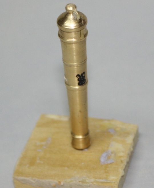
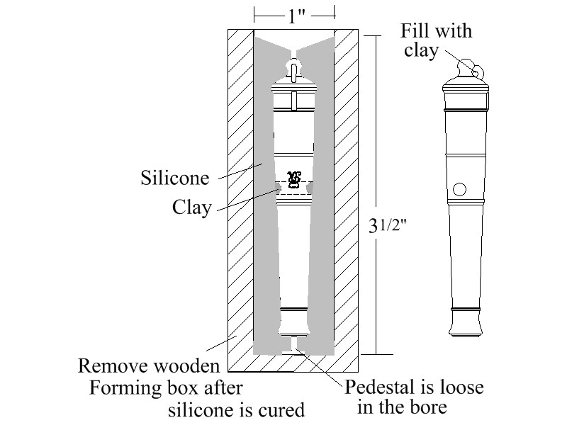
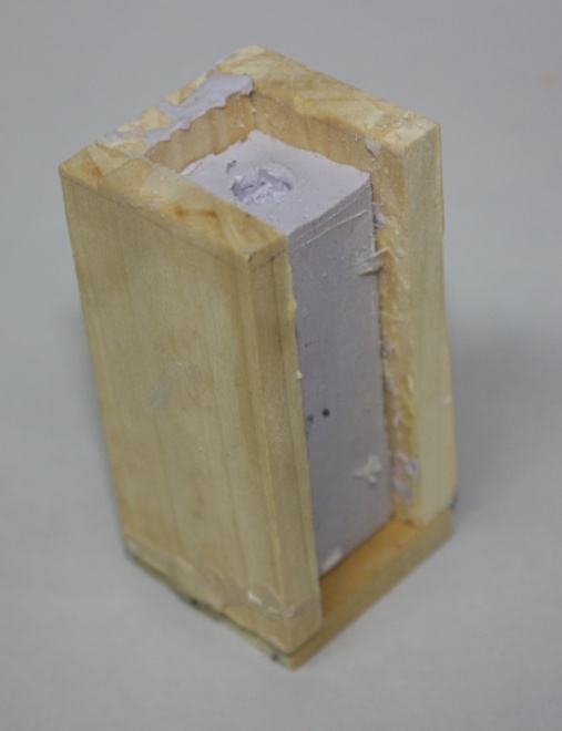
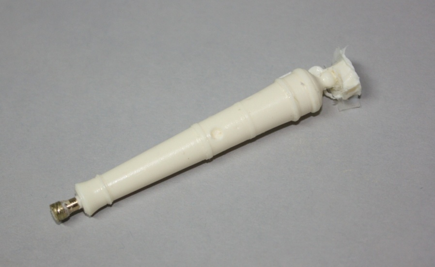
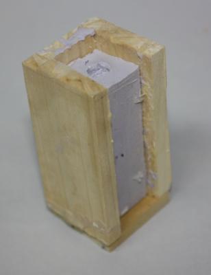
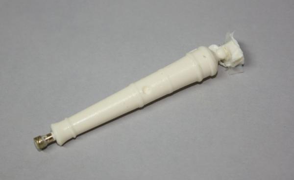
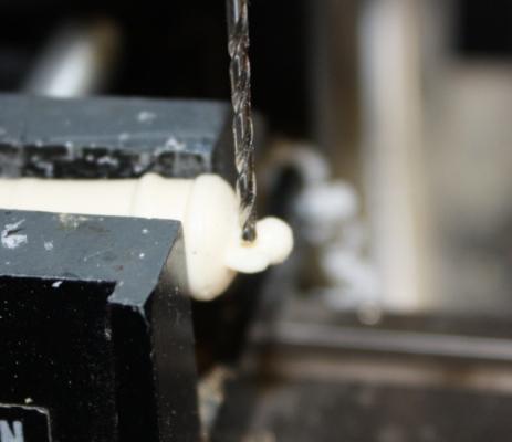
I cannot seem to be able to copy and paste the write up, but have posted some photos of a single piece molding process in the meantime. Allan


-
Janos, I am about 2500 miles from home, but will be back this weekend. I need to reformat the write up and resize the photos from the original used in the Euryalus book. I do not understand how you broke the bold. Was it made with a RTV silicone rubber or something else? I made about 20 barrels with the same mold and it is still in good shape. Allan
-
Gary, Thanks for the update, she really is a beautiful piece of work. And I do like the idea of planking half the deck and being done with it at that point. Have a terrific New Years!!! Allan
-
SUPER!!!! Love the chair arms and seat lattice. Allan
-
Your framing does her beautifully designed lines justice. If her frames were steel, her bow looks like it could have been framed for 20th century frigate or destroyer. Sweet Allan
-
Brian Lavery's book Arming and Fitting British Ships of War has a lot of good information. Adrian Caruana has more, but his books are hard to come by at any price. I believe Lavery has a set of detailed dimensions on a four pounder, but I do not recall if it is right for 1745. Allan
-
I have gone to making and using a single piece mold and eliminated the seam and vents. Works very well for casting resin or pewter. I will try to post details and pics tonight Allan
-
Size of blocks for MS Bluenose 1/64 scale.
allanyed replied to DaveGrady1's topic in Masting, rigging and sails
David, You can make your own blocks with hand tools, including Xacto knife, files, and sand paper. You will need a drill or pin vise as well. There are some very good posts in this forum on block making. You can also purchase them from The Syren Ship Model Company in various sizes but they might not be the same as those in the kit. I would guess those form SSMC would actually be far superior to the kit supplied blocks so may look odd on the rigged model. Allan -
Malc, My preference is start with square stock, make it into an octagonal piece, then round and taper from the end of what is to remain octagonal to the ends. This can be done by hand or by rolling the stock while giving light pressure against a disc or belt sander. If you have a lathe, it is much easier to control the tapering while taking it from octagonal to round. Allan
-
Daniel, Ed is correct. David Steel's Elements and Practice of Naval Architecture (1805). the Shipbuilder's Respository (1788) John Fincham's Introductory Outline of the Practice of Shipbuilding (1821) andthe contemporary contracts that I have seen use the term "round up". I have not seen camber in any of these publications. The 1745 and 1719 Establishments use the term rounding. The Introduction to Steel Shipbuilding (1953), by Elijah Baker refers to this feature as round of the beam as well as camber. I believe camber is more of a modern term in regards to this deck feature. Allan
-
Pillar description
allanyed replied to allanyed's topic in Building, Framing, Planking and plating a ships hull and deck
Druxey, That makes the most sense. Thanks Allan -
Pillar description
allanyed replied to allanyed's topic in Building, Framing, Planking and plating a ships hull and deck
Ron, There is a footnote to the comment" pillars to trance in from each other to the size given 1/4 of their length" Those pillars that come in range of a bulkhead stand contrary to the others, that the sides may be straight, and edges should be taken off with a bold chamfer except those against bulkheads. Allan -
I would really like to have a firm definition of the following use of "trance"in the description of pillars given in the scantlings in the Elements and Practice of Naval Architecture by David Steel. "The pillars to trance in from each end to the size given ¼ of their length" After looking at numerous sites with definitions, the vast majority were of course dealing with mental states, but one gave synonyms of the verb trance as traverse, travel and pass. Traverse could work, but I am not sure. Anyone with a good Old English dictionary? Allan
-
Bill, Good advice from Druxey. I have made masters in metal, then molds using RTVs. If you cast the production run barrels with metal be sure the rubber you purchase will hold up to the temperature for mutilple pours. You can also cast the barrels using casting resin. There are resin dyes so you can tint the resin them cast them gray or black if you wish. I believe you can also get pre-dyed resins as well. You can get mold making supplies from Micro Mark in NJ, Polymeric Systems in Phoenixville, PA and a few other places. I have used two piece molds and have never been happy as there is always a seam. You can in fact cast the trunnions using two piece molds, but for me, the work to get rid of the seam is far more cumbersome than using a single piece mold then adding the trunion. I have yet not been able to successfully cast the trunnion in a single piece mold. Allan
-
Ed, I do like the idea of the monofilament. Any problem with the ends being too shiny? Regarding the tinted glue, is there a reason you choose to use the powdered pigment versus a liquid acrylic paint? I have used the latter with no ill effects. It does not take much paint to tint the glue if using a good professional artist color that is heavily pigmented so there are not worries of "weak" glue. The first time I tried it I did test pieces and the wood broke away before the seam. Thanks Allan
- 3,618 replies
-
- 2
-

-
- young america
- clipper
- (and 1 more)
-
Ed I have never ever thought about building a clipper. I was OK watching your first posts and was enjoying just looking at the great work. But now that the framing is coming along you have gone and messed up my schedule big time as I try to figure if I could juggle my projects to fit in such a project over the next few years. Great work Ed, on all counts. Allan
- 3,618 replies
-
- 2
-
-
- young america
- clipper
- (and 1 more)
-
Thanks to everyone for their comments, they are very much appreciated. Allan
-
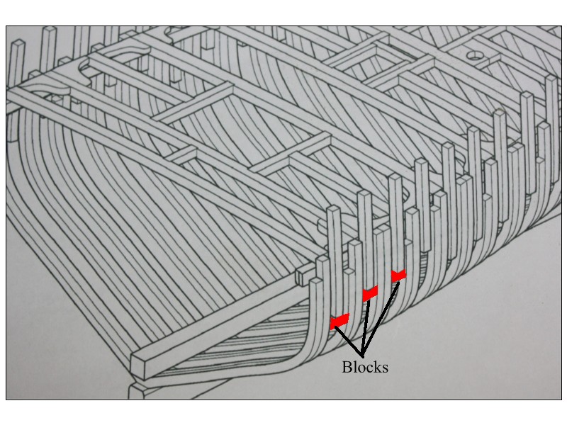
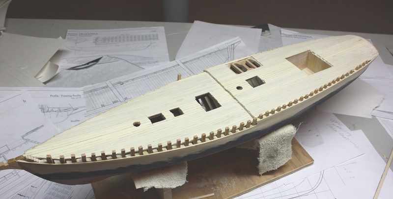
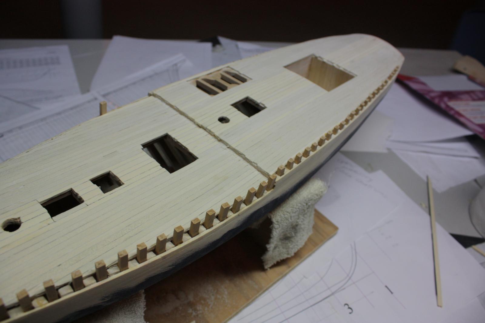
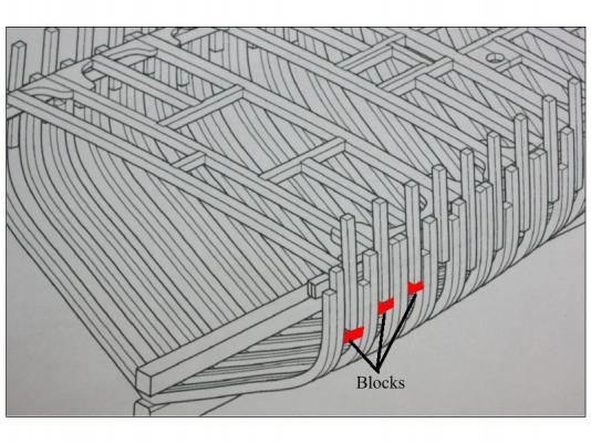
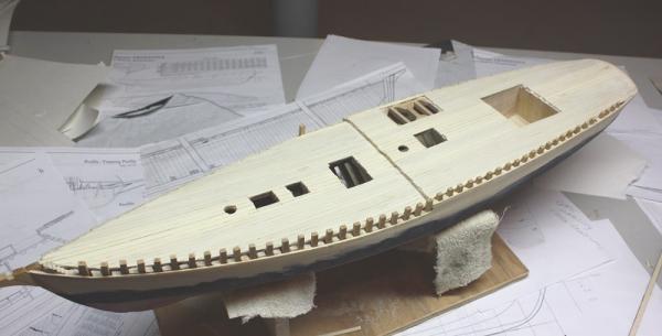
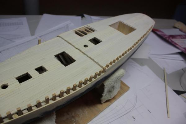
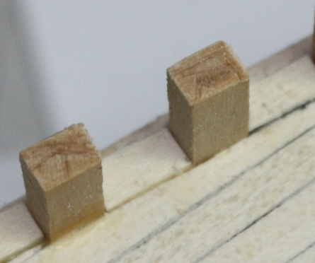
A bit of progress on Effie. The deck is planked and scraped, but needs a bit of trimming around the various deck openings. With no top timbers on the frames, sanding and scraping the deck planking was easier than when there are bulwarks or top timber framing in place. There are stanchions between frames versus having top timbers on the frames. The frames stop at the same height as the top of the deck beams so the stanchions will be the support for the bulwark planking. When framing the model I placed small blocks between frames to give added strength. Coincidentally, these act as a stop for the stanchions. I have drawn these blocks in red on the attached. I have started fitting filler decking pieces between the stanchions to close in the decking around the stanchions as shown on the photo. Allan
- 86 replies
-
- 12
-
-
- schooner
- effie m morrisey
- (and 1 more)
-
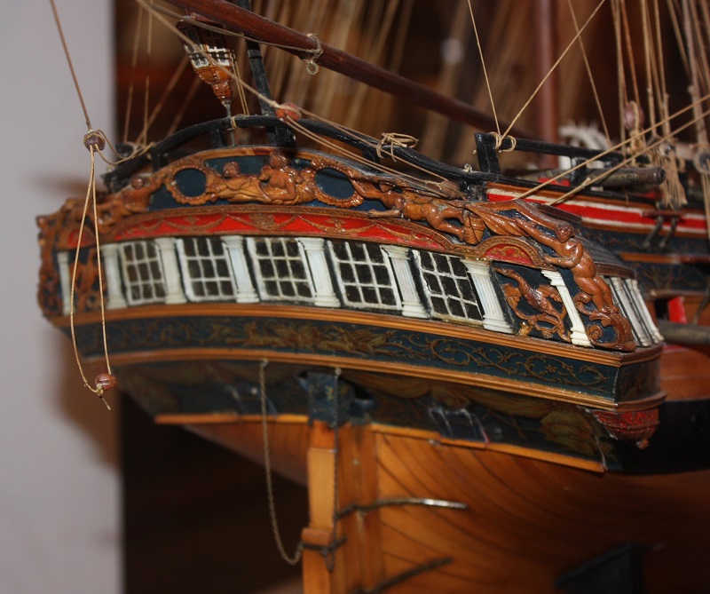
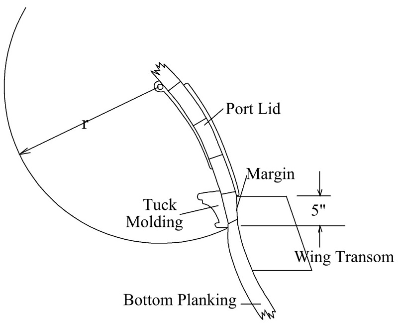
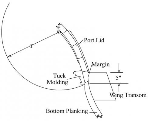
Druxey, You may very well be right in that your drawing has a rail that truly "tucks" in between the counter planking and hull planking. I can not quite tell from the contemporary model photos that I dug through, but they truly look to lay over the seam of the planking. I did dig through my NMM drawings and they do not show enough detail to indicate a tuck nor a laid over tuck rail. Would love to find a contemporary drawing showing this. I found the attached at the NMM Collections site when doing a search for "Stern Rail" The rail does not look to be laid over the planking as I had surmised but much closer to what you show. Sure looks like a "fun project" making the rail as shown on the photo. Allan
-
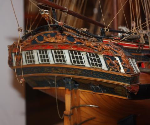
Also watch to see if the tuck rail crosses the ports. The following sketch and photo of the Leda, a contemporary model in the Rogers collection show this. Allan
-
Frazer, Each deck has a different round up (which is the earlier term for deck camber.) Which decks will be visible on your model? The round up for various size ships can be found in the Establishments, but I believe the earliest Establishment is more than 60 years later than Sovereign so there may be no definitive answer available. Allan
-
Wayne, Are the frames in two pieces or one? I cannot imagine a tree wide and long enough from which a complete frame can be cut to cover the height and beam. Maybe a giant redwood? Allan