allanyed
-
Posts
8,149 -
Joined
-
Last visited
Content Type
Profiles
Forums
Gallery
Events
Everything posted by allanyed
-

Edge bending planks
allanyed replied to ortho85's topic in Building, Framing, Planking and plating a ships hull and deck
Dan, I do remember your jig and I have not doubt it works, but for me, it is easier and quicker to spile a plank. Again, to each his own, there are always multiple ways to skin the proverbial cat. wq, (I really wish you would share a name...if that is truly your name, how is it pronounced? ) No push back taken, no problem there, this has been a good discussion and hopefully has not caused too much confusion for those that have tried neither method up to now. In the end we will probably find a fifty/ fifty split for the newbies. Cheers Allan -
Edge bending planks
allanyed replied to ortho85's topic in Building, Framing, Planking and plating a ships hull and deck
Hi wq3296 You described what I think are stealers that fill gaps, typically at the stern. Spiling is shaping every plank as there are no standard planks on a ship other than perhaps the straight pieces found in the quick work. If you take a look at a drawing of the planking expansion available for some of the old ships, every plank has some shape to it other than straight and each strake varies in width across its length. Some widen near the stern, most, if not all reduce near the bow. Granted, some of the pieces of a given strake near the dead flat will be so close to straight that slight bending can easily be done at the scales we use. All of this is explained in good detail in the tutorials in this forum. Allan -
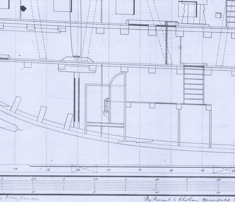
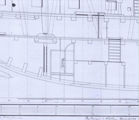
Daniel, It appears that Rob is following the drawings closely. Attached are sections from the original plans for Blanche, Euryalus, et al. the aft magazine is indeed quite a small space. Allan
-
Edge bending planks
allanyed replied to ortho85's topic in Building, Framing, Planking and plating a ships hull and deck
Hi Augie, If you bend the wood first, as with your jig, is it difficult to mark and taper each piece? The taper is not a constant from widest portion to narrowest, and each plank ends at a different point along the length of the hull so each piece has to be shaped slightly differently. The jig would have to be modified quite a few times as the curve changes for every strake, especially at the bow. I would think it is much more difficult and time consuming to mark and shape the taper on a prebent plank even if you do not modify the shape of the jig more than a few times as the planking goes on. In the end, whatever works well is a good thing! Allan -
Alan, The frames were beveled inboard and outboard so there was a fair line running from stem to stern and to give a flat surface on which to fay the strakes of planking. Your picture on the right is the what you need to achieve. As you get nearer the bow and stern, the beveling was extreme before cant frames became the norm early in the 18th century. The green line on the stern looks odd to me. What does this represent? Thanks for sharing your work with us. Allan
-
Edge bending planks
allanyed replied to ortho85's topic in Building, Framing, Planking and plating a ships hull and deck
If the wood is soft and wet you can slightly bend (edge set) and it will stay in that shape when dry. Harder woods cannot be easily edge set and will lift. There are several write ups on this site on planking, including spiling. Why fight the wood when you can cut it to the shape that will allow it to lay without trying to fight the wood? Allan -
HMS Euryalus by egen -
allanyed replied to egen's topic in - Build logs for subjects built 1801 - 1850
Egen, In the Arming and Fitting by Brian Lavery he goes into these pumps in some detail. Between several designs by Coles and Noble, there are at least two designs that could have been on Euryalus. The last design by Coles was in 1803, but it was not successful and they were removed. Look at the contract in Volume I and you will see confirmation of what Ed T mentions above. It specifically forbade inclusion of masts, pumps, and stove so without a bill of sale, bill of materials or some such paper work there is no telling what was installed. Allan -
Ciao Mauro, Your Lettie Howard is looking very nice. Do not forget to scrape a little of the paint on the bulkheads when you glue on the bulkhead stanchions so the glue gets into the wood. . Are you going to include the foretop mast or leave it off as she is rigged today? Thank you for posting the photos.
-
Drake, Before using lip balm, take a look at the ingredient list and then make sure they are compatible with the rigging line material you are using. There a number of oils and fragrances. and other chemicals, some of which may be harmful to the rigging line over time. Bees wax by itself has no payoff on the lips, it is much too hard so softeners are added. Allan
-
My oh my what a great mini project! Of course now I have to try this, and once again explain to the boss when she asks why I have patience to try these kinds of things, but little else. I will be blaming you of course, so you are forewarned. Allan
-
Ed Your attention to the smallest detail is what puts you on a different level. Most builders are not even aware of the details to which you have paid attention, let alone incorporate them into the build. Allan
- 3,618 replies
-
- 1
-

-
- young america
- clipper
- (and 1 more)
-
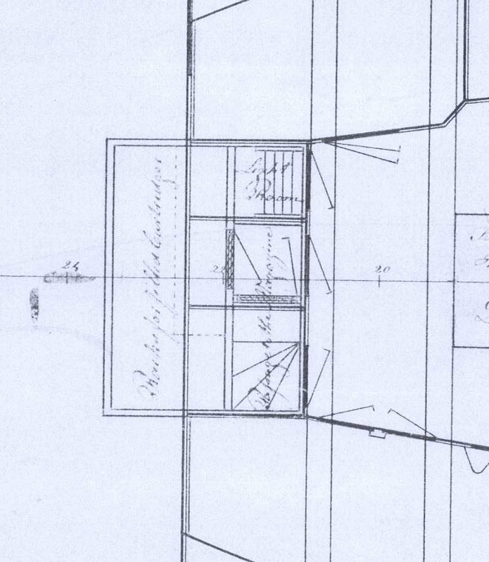
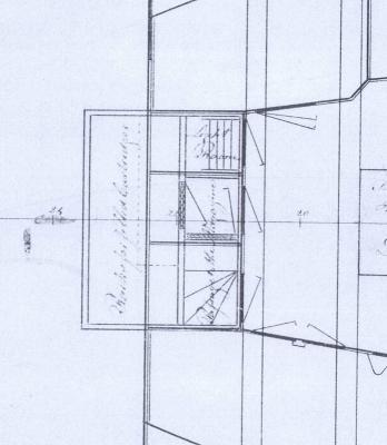
Druxey, I thought the same thing about the lanterns being opened in the room if it was not the magazine. The drawing I posted earlier, and especially the one below gave me pause. Why are there bulkheads forming a little room to the back of the lantern rather than just opening the lantern inside the gunner's room. Would there be loose powder normally present in the gunner's room? Thanx Allan

-
Remco, Your build is exceptional and a pleasure to follow. I do have a bit of confusion in my own mind on the bulkhead lanterns. This is not a criticism as the lanterns are VERY nice. They are showing exactly opposite each other. I always thought, (and very possibly incorrectly) that the access to the bulkhead lanterns was from the opposite side of the bulkhead much like the lanterns in the light room. The attached drawing seems to indicate access through the bulkhead, thus my comments. Of course they could have hinged doors inside the room and hang them as shown on Kingfisher, but it was a new one for me, or at least the first time I remember seeing this configuration. Thanks again for sharing your build. Allan
-
Help with king plank
allanyed replied to captainbob's topic in Building, Framing, Planking and plating a ships hull and deck
Bob, The drawing of the Ernestina shows what appears to be a king plank on the raised portion, but none forward. Different vessel, different designer, so maybe one of those "either/or" situations. Photos of her deck indicate a king plank aft, as well. Allan
-
Robert, The breech rope does appear that it will cause the rings to flip and jam the rope. It is also highly unlikely that the running tackle on cannon on a cutter, would have a double and single block on each side. Two singles on each side were the norm except on 32 pounders according to the History of British Sea Ordinance 1523 to 1875 Volume II, by Adriana Caruana. Allan
-
Further to Gary's post, these were called half bucklers and blind bucklers, the latter of which fully closed off the hawse hole inboard on British ships, at least in the 18th century and into the 19th century. There may have been other methods, but this seems to have been at least one common method of keeping out the water. The manger was present as well to help contain water (and mud, when the hawsers were brought in when raising the anchor) There were relatively large scuppers in this area of the manger as well to let the water run off. Allan
-
Danny It will be a sad day when the work is finished, for those of us following your build. I may have missed in an earlier post, but is rigging in the future for the Vulture? Allan
-
Rob, When you get to that transom, fire away with the questions. I am sure Wayne or I will be able to help, at least I hope so. Another book??? I swore never again, but........ Allan
-
Ed, I would be delighted to display the hull in a prominent place just as it is! Allan
-
So noted Ed, and I rely on your experience that it is a better way to go,,,,,,, but it sure looks like a tempting thing to try. Allan
-
Ed, Presetting the half frames with the cross spall is so simple yet effective. I will remember one for sure. Now, how about something cleaver for setting pairs rather than individual cant frames? Allan
-
Rob, Thanks for the latest posts, it is really nice for me personally to see her coming along so nicely. Allan
-
Sherry, You can try to contact Polytek (www.polytek.com) and/or look at some of their Youtube videos. We use several of their RTVs for making molds for our automated lipstick molding machines, and I also have purchased RTV's and casting resins from them in their Easy Flo line of products. Great stuff. Allan
-
Ed, I don't which I like more, the home made clamps or the stern framing. Great work all around! Allan
-
Good bye, loosening knots!
allanyed replied to Ulises Victoria's topic in Masting, rigging and sails
Thanks for the idea. Is there any potential negative long term effect from a chemical incompatibility with the rosin and various rigging line materials such as cottton, linen, &tc? Thanks Allan