


allanyed
-
Posts
8,088 -
Joined
-
Last visited
Reputation Activity
-

 allanyed got a reaction from GrandpaPhil in Spanish Galleon Keel Wood?
I believe the most common species for keels were oak and elm as pine was relatively weak for large vessels. Regardless you may find all of these are much too grainy for your model. The below shows these species compared to a couple other choices commonly used on model ships, Alaskan cedar and Castello boxwood. English/European box is great but costly. Basswood and poplar is less grainy but you might find them too soft for a keel.
Allan
-
 allanyed got a reaction from Bob Cleek in How to make flat rope coils?
This may be a little bit on the edge of the rope coiling topic which has been very informative. Now I know where the beer logo came from or more likely the other way around and the rope coils are named for the beer logo. If there is indeed really some connection with the Ballantine name for what looks similar to Borromean rings the connection with the rope coiling name may be related. Ballantine opened their brewery in 1840 but the logo came about nearly 40 years later. Legend has it that Peter Ballantine saw three wet rings from bottles on a table that overlapped and came up with the logo from that.
Allan
-

 allanyed got a reaction from Coyote_6 in Masts and Bowsprit - Glue or Not?
I thought contemporary drawings of masts may help, including the shape of the foot or heel but of the ten high res plans that I have found, to my surprise none of them show the heel itself as the drawings stop at what appears to be where top of the step would be. Lees does not address the heel of the fore, main, or mizzen mast that I can find in The Masting and Rigging English Ships of War. Hopefully some member can shed more light on this. Peter Goodwin does give some detail on the steps in The Construction and Fitting of English Man of War as follows:
In general the step for each mast consisted of a large baulk of timber, usually oak, fashioned in such a manner that it straddled the keelson. A mortice was cut vertically into the upper surface in which the tenon of the heel of the mast sat....... The mortice and tenon were always made to the following dimension: The tenon at the heel of the mast was half the diameter of the mast in the fore and aft plane, and had a width two thirds of the diameter of the mast athwartships. The depth of the of the tenon was usually about half the diameter of the mast.
I suspect this is generally good information but would be very surprised if were not variations in the dimensions.
Allan
-
 allanyed got a reaction from brunnels in B-25J Mitchell by Chadwijm6 - HK Models - 1/32
One of my all time favorite planes. Luckily I got to see one up close and personal and get on board the B25 owned by Ed Browing's Red Baron Flying team which sponsored Daryl Greenamyer's low altitude speed record flight over Mud Lake, Nevada. Great story and one of the greatest thrills of my life to work for one of the sponsors and be there to see it in person. A bit off topic but for an interesting read - https://www.916-starfighter.de/F-104RB_RedBaron_AirProgress1977.pdf
Allan
-
 allanyed got a reaction from hof00 in Deck Planking Shift of Butts - Flying Cloud 1851
Hi Harry,
Have you looked at the Young America 1853 build log here at MSW and/or Ed's book and plans on her? Maybe it will be applicable to Flying Cloud. If you have not already seen it go to post #131 in https://modelshipworld.com/topic/10678-young-america-1853-by-edt-finished-196-pob-extreme-clipper/#comment-322547 It continues for a number of posts on planking the various decks.
Allan
-
 allanyed got a reaction from Scottish Guy in Masts and Bowsprit - Glue or Not?
If the foot of the mast is properly shaped to being square and rests in a square hole in the step it will not rotate and the rigging will hold it down. If the mast is round at the foot and can twist while rigging is applied it would probably be better being glued in place.
Allan
-
 allanyed got a reaction from Gregory in Spanish Galleon Keel Wood?
I believe the most common species for keels were oak and elm as pine was relatively weak for large vessels. Regardless you may find all of these are much too grainy for your model. The below shows these species compared to a couple other choices commonly used on model ships, Alaskan cedar and Castello boxwood. English/European box is great but costly. Basswood and poplar is less grainy but you might find them too soft for a keel.
Allan
-
 allanyed got a reaction from paul ron in Masts and Bowsprit - Glue or Not?
If the foot of the mast is properly shaped to being square and rests in a square hole in the step it will not rotate and the rigging will hold it down. If the mast is round at the foot and can twist while rigging is applied it would probably be better being glued in place.
Allan
-
allanyed got a reaction from Coyote_6 in Masts and Bowsprit - Glue or Not?
If the foot of the mast is properly shaped to being square and rests in a square hole in the step it will not rotate and the rigging will hold it down. If the mast is round at the foot and can twist while rigging is applied it would probably be better being glued in place.
Allan
-
 allanyed got a reaction from Keith Black in How to make flat rope coils?
This may be a little bit on the edge of the rope coiling topic which has been very informative. Now I know where the beer logo came from or more likely the other way around and the rope coils are named for the beer logo. If there is indeed really some connection with the Ballantine name for what looks similar to Borromean rings the connection with the rope coiling name may be related. Ballantine opened their brewery in 1840 but the logo came about nearly 40 years later. Legend has it that Peter Ballantine saw three wet rings from bottles on a table that overlapped and came up with the logo from that.
Allan
-
allanyed got a reaction from Keith Black in Hello from Iowa
Love the Pave Hawk model! WELCOME ABOARD!
Allan
-
 allanyed got a reaction from davyboy in Spanish Galleon Keel Wood?
You mention European built vessels so there would be differences with those built by Spain in Havana and the Philippines. I have no idea how accurate the following article might be, but it may be a little help.
https://www.worldhistory.org/Spanish_Galleon/
Allan
-
 allanyed got a reaction from Pete Fleischmann in Hello from Iowa
Love the Pave Hawk model! WELCOME ABOARD!
Allan
-
 allanyed got a reaction from druxey in Deck Planking Shift of Butts - Flying Cloud 1851
Hi Harry,
Have you looked at the Young America 1853 build log here at MSW and/or Ed's book and plans on her? Maybe it will be applicable to Flying Cloud. If you have not already seen it go to post #131 in https://modelshipworld.com/topic/10678-young-america-1853-by-edt-finished-196-pob-extreme-clipper/#comment-322547 It continues for a number of posts on planking the various decks.
Allan
-
allanyed got a reaction from paul ron in How to make flat rope coils?
This may be a little bit on the edge of the rope coiling topic which has been very informative. Now I know where the beer logo came from or more likely the other way around and the rope coils are named for the beer logo. If there is indeed really some connection with the Ballantine name for what looks similar to Borromean rings the connection with the rope coiling name may be related. Ballantine opened their brewery in 1840 but the logo came about nearly 40 years later. Legend has it that Peter Ballantine saw three wet rings from bottles on a table that overlapped and came up with the logo from that.
Allan
-
 allanyed reacted to newbee in HMS Diana 1794 by newbee - Caldercraft - 1/64
Thanks to everyone for dropping by and also the likes.
The first thing I should mention , in my last post, the wale sits way too high both fore and aft. I think I got a little carried with thinking Ihad the correct shape until I realised later. I aplogise for this mishap.
I wanted to get the final positioning of the gunports right so I could measure down from them to get the position of the wale and then complete shaping the stern below the lower counter. I copied several photos and drawings and found none of them coincided with the hull I have. I went back to the plans of the kit and, despite the instructions having the wale 21mm wide, they are shown as being 18mm. Unfortunately, on the plans, the gunports are of no use as the they do not run with the deck. Looking at various pictures it appears that the distances between the gunports, the waterline and the bottom of the keel are 1/3 gunports to waterline and 2/3 waterline to keel. finding this out as a by the way didn't help me but could maybe help others. Anyway. As I couldn't measure down from the gunports I would have to work up from the waterline. Unfortunately I found that, having highlighted this with a pen (between 1and 2mm thick) I would have to guesstimate a little. I measured the gap between the lower edge of wale and the waterline on the plans and marked these onto the hull apart from the mid section which I wanted to be 2mm higher rather than the 1mm shown. Once I had marked these points on the hull I pinned a 4mm strip along the hull. This does not only have, I think a flowing curve, but also almost perfectly matches the shape I have at the stern. My first thought was that I may need to add a little filler or balsa between the lower counter and the deadwood area but then realised that there will be 1mm strips added beneath the wale, the second planking, so I think I just need to add a little filler and then smooth everything down. The next step will now be to add the dummy stern post and finalise the taper of the deadwood. I feel so relieved that the stern appears to be nearly done and delighted that I've finally figured out the run of the wales. Unless anyone can see something wrong (unless I beat you to it)!!!
Here's the latest photo's anyway.
Cheers for now.
David.
-
allanyed reacted to rwiederrich in How to make flat rope coils?
Well....I'm simple man and I never gave it to much thought...as to many techniques. For all my models....I use a simple method. I just spread a thin layer of clear drying wood glue on a plastic surface.
Then I simply begin in the center and roll around the rope on itself edge to edge...till I have the desired amount laid out. Then using a sharp tool or tweezer, I slowly pic it up from the glue and relocate it on the area needing a rope coil. I make some mods...adjusting for proper lay and....Shazamm! It stays exactly where placed and it dries clear. I use this method for all rope coil needs.
Here is a pic to show the finished item.
Rob
-
allanyed reacted to Pete Fleischmann in Hello from Iowa
Hello all!
new to the forum! Never built a ship; but will start a new build soon! I’m mostly an aircraft guy- here’s a 1/35 HH-60G I finished a year ago-
looking forward to advice and insights..plus a lot of inspiration!!
cheers
Pete
-
allanyed reacted to Roger Pellett in Exploring different ways of hull construction
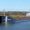
Great Lakes vessels in bulk cargo trades are long, narrow, and shallow draft. Designers, therefore, are hard pressed to provide adequate structure to stiffen the hulls. Even so some ships flex uncomfortably in rough water.
The model that John wants to build will exhibit the same problems without internal structure. A light plastic shell without such reinforcement will behave like a wet noodle.
The simplest approach is a wooden hull. Since these Seaway sized vessels are 90% parallel mid body this can be a hollow open topped box with deck beams and deck added to the carved hull later. The bow and stern can be laminated and designed to fit the ends of the box. The bilge radius is easily shaped with a router and the bow and stern shaped by conventional carving techniques.
These ships are built with all butt welded seams. Plating is flush with perhaps 1/8” external reinforcement of welded seams (about .01” at 1:96 scale). Lapped plates or heavy weld lines are therefore incorrect on a model. Proper finishing to eliminate wood grain will produce a true to scale model.
Roger
-
allanyed got a reaction from Scottish Guy in Exploring different ways of hull construction
From surfing the net it appear that styrene softens at 212F or a bit higher. Styrofoam is about the same so does not sound like it would work based on this information. A wooden plug made of poplar, pine or balsa that would be removed after the hull is formed may be best. I look forward to seeing the final answer to this one.
Allan
-
allanyed got a reaction from Scottish Guy in Exploring different ways of hull construction
Hi John,
For the plug, have you considered styrofoam as an alternative to wood then heat and form styrene around the plug? For the area such as at the stern it may be easier to make that area of the plug out of wood to withstand heavier bending. MAYBE this video will give you some ideas. https://www.youtube.com/watch?v=AxP3vtQxVtw for the shaping of the styrene sheets. There is at least one MSW member that has made beautiful hulls for "steel" ships using alternative materials. Hope he sees your post and responds.
Allan
-
 allanyed got a reaction from Archi in LˇAmarante by marsalv - 1:36 - POF
Beautiful work! Can you share what material you used to make the piece in the photo below and how you made it?
Thank you
Allan
-
allanyed reacted to gak1965 in RRS Discovery 1901 by gak1965 - 1:72 - First Scratch Build
Brief update. Followed the plan described above. I took two pieces of 1/4 by 1/8 bass, taped them together so that the two pieces would be identical, and marked off the 3/32" squares, about 0.7 inches apart, and then started cutting out the 3/32" slots.
Here are the two pieces ready to start installing.
I soaked them in boiling water to get them to soften for improved bending, and put them on the ship, held in the correct orientation with some clamps and nails to 'prebend' prior to installation.
Once dry, they were installed, I glued them into place. Other than some minor smoothing of some of the bulkheads. I can start planking once the lumber arrives.
Thanks for looking in!
Regards,
George
-
 allanyed got a reaction from JKC27 in Exploring different ways of hull construction
Hi John,
For the plug, have you considered styrofoam as an alternative to wood then heat and form styrene around the plug? For the area such as at the stern it may be easier to make that area of the plug out of wood to withstand heavier bending. MAYBE this video will give you some ideas. https://www.youtube.com/watch?v=AxP3vtQxVtw for the shaping of the styrene sheets. There is at least one MSW member that has made beautiful hulls for "steel" ships using alternative materials. Hope he sees your post and responds.
Allan
-
allanyed reacted to Roger Pellett in alcoholic stain on blocks
There is actually an example of a British built warship from this same era, carefully restored: HMS Warrior. She is on display at the Portsmouth Royal Navy Museum. Pictures of her should be easy to find on the internet. Look her up. What color are her blocks.
Roger