


Jaager
-
Posts
3,084 -
Joined
-
Last visited
Content Type
Profiles
Forums
Gallery
Events
Everything posted by Jaager
-

Converting a Backyard Shed into a Model Workshop
Jaager replied to Hank's topic in Modeling tools and Workshop Equipment
Hank, Starfoam is how coworkers who were from eastern KY pronounced Styrofoam. (The patient water glasses at our VAMC were actually beaded starfoam cups.) A door with hinges at the top - to seal the storage cubby. When I imagined this solution, I envisioned the opening as being pentagonal - and thought that two half doors would do the job - but it looks like you finished it to be rectangular, so one will do. A loop of bungee cord for a handle - a gaff hook to pull it open and place the loop in the hook that keeps it open. American Science & Surplus has a tube of 29 plain donut magnets for $6.00. They are strong enough to keep a seal if paired and 4 or 5 sites are used. The only downside is the spam catalogs - but the paper is the right stuff for starting a fireplace log. -
Converting a Backyard Shed into a Model Workshop
Jaager replied to Hank's topic in Modeling tools and Workshop Equipment
Hank, I would give serious thought to using a sheet of 2" Starfoam (E.KY) insulation. It probably only comes as 4x8. One sheet may get you a double layer. Hinge it along the top edge. A long pole can keep it open or a distal hook in the ceiling and a loop with the sheet. It may require 1/4" ply to hold the hinges. It is porous enough for PVA to hold it all together. LiquidNails also works. Weather stripping along the border and strong magnets at few points to hold it all closed tight. -
BUYING A "PAINT SET"
Jaager replied to MadDogMcQ's topic in Painting, finishing and weathering products and techniques
Some of the old books about how-to model ships suggest dry pigments (Japan?) I wonder if the dry or oils are minerals and the acrylics are organic? The chemical industry started with the synthesis of organic pigments. But complex organic molecules are much more subject oxidation than minerals, some of which may already be oxides. As a practical matter on the subject of the desirability of using archival materials, although I completely agree with you, I suspect that the issue will soon prove to be a moot one. We have already passed an inflection point and show no indications of having the will to do what is necessary to avoid generating one or two more. -
I believe that the Physics involved would require sideways movement with both fixed guns and guns that recoil. The amount of movement and if it was enough to be observed is another factor altogether. The greater mass of the ship and the resistance of the water suggest that when the equations are run, the number would be a small one. Today, with our tech, a real number could be measured. It might be mm or cm but the force has to go somewhere. If it were localized at the points of attachment to the side of the ship, it would be just compression of a small volume of wood that absorbed these forces. The body of the ship is a series of interlocking components that were built to transfer and diffuse these significant forces.
-
Mark, I think this is a lot more involved. If the projectile was frozen in place and the charge ignited, the gun would not move. It would be a bomb and if it remained intact, a pressurized vessel. The force of the recoil is equal to the mass of the projectile times the gas expansion velocity squared (while the projectile is in the system). The rate of gas generation - the gas pressure - has a more significant effect on the projectile. Recoil or no recoil, the gas pressure in the chamber does not change. Flames coming out of the mouth of the cannon before the projectile = a poor fit and much loss of pressure pushing it. Flames coming out long after the projectile has left = slow and inefficient generation of gas, gas that is pushing against atmosphere instead of a solid.
-
There is more movement than that in the visible range. The atoms are what is actually being subjected to the force. I think that a segment about an F86 in Korea demonstrates some of the forces. There was something like 6 or 8 50cal mounted in the nose. A first generation pilot said that they had to be careful when chasing a MIG, not to fire too soon. Firing the guns slowed the F86 down enough that the MIG could pull away. The shipboard cannon would impart rearward force on the side of the ship. If the structure held, that force would be transferred to the whole ship. The ship would move backward. It might be difficult to measure and it might not be significant, but I suspect that in a stern chase, a fixed gun firing would widen the gap between two ships enough to matter.
-
Mark, I suspect that the reasoning behind fixed guns is specious. I remember all those pesky force vector lines from Physics. I believe that the reverse direction force would be at the point of attachment of the gun to the ship. Very little was probably redirected to the back of the projectile. This does not mean that the time frame for the development of tactics for the use of guns at sea was any different. What was believed to be true the determining factor. The later method of allowing recoil and the dispersion of the reverse force over multiple points of attachment probably saved wear and tear on the body of the vessel. Another thought: at the point of combustion, the force is spherical. Would not some of the compression of the atoms of the breech be converted to heat?
-
Accurate Triangle metal square
Jaager replied to michael101's topic in Modeling tools and Workshop Equipment
A machinist square? -
Acrylic clear over India Ink
Jaager replied to ChrisSC's topic in Painting, finishing and weathering products and techniques
This discussion has me wondering a bit more about scale effect as it applies to color. I am wondering if @ 1:600 the black would look better if it were actually a very dark grey. If it is an Atlantic Ocean vessel, just a slight hint of green in the dark grey? -
Acrylic clear over India Ink
Jaager replied to ChrisSC's topic in Painting, finishing and weathering products and techniques
India ink is very small particles in water - maybe graphite? - carbon anyway. When I was a pup, a drop on a microscope slide was a method of displaying brownian motion. It is essentially a dye. It penetrated porous surfaces and stays behind when the water dries. Plastic (your type -styrene) has no pores. The ink is just a dirt layer on the surface. There is no chemical reaction involved. Paint involves a chemical reaction. Your clear finish also involves a chemical reaction. From your description - a speculation: the carbon particles suspend in the water solvent of the poly finish and interfere with the polymerization reaction. It may never dry or if dry the incomplete reaction may leave mostly poly monomers which are essentially just another dirt layer. In this case, the product is named after a reaction that does not occur, so it is nor poly at all. -
D., If you have not already done so, I suggest that you read the pinned post just above this one: For Beginners -- A Cautionary Tale May your attendance here be long and rewarding.
-
John, Your diagrams in post #1 and post #4 are quick and dirty POB kit shortcuts . The final appearance would be essentially the same as actual practice. But what you show is very different from actual practice. The actual waterway is a thick and wide timber, with 5 surfaces in cross section. It butts against the inside face of the top timbers. It has a slope or bevel on the top inside corner. The kit saves itself lot of work by calling a triangular strip of wood - the waterway. It is just the bevel of the waterway. The margin plank ( and the waterway ) sat on a mortise/notch cut into the top of the deck beams. The margin plank(s) are about twice thickness of the deck planks. They add strength at the side and lock the waterway in place. On the surface, none of this is seen. The kit uses deck planking as the margin plank. I hope your drawing is not to scale. The margin plank needs to be wide enough to take the nibs. The deck planks should be 10" wide at the maximum. A smaller ship may only have one strake of margin planking? The spirketting as a sort of inside wale. It provides strength and is also subject to stress from the forward cannon trucks. It actually sits on the waterway and reaches the underside of the gun port sills. The inside bulwark planking starts above the spirketting and is maybe about one half the thickness. In Gary's post #3, the four strakes of top and butt are on the main (gun) deck of a frigate. They lay under the monster size guns. I can imagine the on recoil that those guns may hop as well as jerk on the rope springs and ring bolts at the spirketting. Planks with added thickness and interlocked joinery for the stress there. I doubt that is detail would apply to Lady Nelson.
-
This is straight out of my head, so no pictures. Most table saws that can do a rip cut that is other than 90 degree vertical - tilt the blade. The Byrnes saw holds the blade vertical and tilts the table - the right of the blade part of the table. Kurt and No Idea suggest that because of gravity and friction, the wood can move away from the blade -because it mostly rests on an angled surface. They mimic the standard table saw by tilting the blade, and making the accessory table horizontal. The rest of the saw goes with the blade. The saw comes on its own base. A heavy one. They place wedges under the base to angle it up. I would want a stop at the right side edge to keep the saw from sliding. My suggestion is more elaborate and only makes sense if a whole lot of beveled ripping is going to be done, and if several angles are involved. My picture: Lay a book flat on a table. Turn it so that the top of the book is facing you and the spine is on your right. Lift the front cover. Imagine a small version of the saw sitting on the top cover. The cover is lifted until the right side saw table accessory is horizontal. Use plywood to make the two book covers. Use a full size piano hinge as the book spine. There are holes in each corner of the saw base. Fix the saw base to the top piece of plywood. As heavy as the saw is, I think two pieces of 1/2" ply will be needed. The bottom needs to be wider than the top - enough beyond the hinge the the whole assembly does not flip sideways. The threaded rod and nut are not needed actually. A block of wood, square even will hold the top cover at the angle. A way to fix it in place would probably be a good idea.
-
If the object is to be able to get a precise and reproducible saw tilt and this will be done frequently with multiple possible angles being cut: Fix the machine to a two plywood sheet base. Lower is a 1/2" - 3/4" sheet. width 3" or more wider than saw base on each side. Upper is 1/4" sheet The right edge of upper sheet is at the right side of the saw base. The upper sheet is attached to the lower using a full size piano hinge. The left side is as far beyond the base of the saw as is needed to fix a a threaded rod and thumb screw or wingnut to raise that edge. There would probably need to be spacer pieces at the hinge and outer edges of the upper sheet that are a tad thicker than the thumb screw/wingnut. Someone really OCD could fix the angle gauge from a adjustable miter - or a stick with marks at the front right at the hinge. The down side is that it adds weight to an already hefty machine. A 1" rubber stopper fixed under each corner of the base will provide space for fingers to lift the machine, if it just rents bench space and lives on a shelf.
-
Source For Gloss Varnishes
Jaager replied to ir3's topic in Painting, finishing and weathering products and techniques
I did a Google search using: Blackfriars Light Oak Gloss Varnish Clicking on the company site link Their products are solvent based polyurethane varnish. There is no shortage of quality brands at your local builders supply mega store or a hardware store. The volume that you will need = you could probably return it after using what you need and it would pass as full. Not a suggestion for possible behavior. It is meant as an exaggeration. There are oil stains that mimic light Oak from several mfg from the same vendors. The surface area that you will be covering is small. Stain and finish as two steps instead of one, will not cost you all that much more time. I suspect that the original instructions are trying to save you money. It may save you money if you contact your local woodworkers guild - Someone there is likely to have leftover gloss polyurethane and left over light Oak stain. (Or a local cabinet maker.) I cannot resist an editorial. These are "unique" instructions for a scale model ship. Solvent based polyurethane produces a thick layer. It was great for my Walnut stained White Oak kitchen floor in KY. Not good practice on a scale model. It is a thick plastic layer. Gloss - is an out of scale finish on a scale model. I am guessing that this is an actual working motor craft that is intended actually float. This moves it to the toy category and that makes gloss appropriate. The exposure to water makes solvent based polyurethane and gloss appropriate. Because most Pear seems to be Swiss Pear - that is, it is steamed and therefore a darkish red and uniform in color, the Oak stain probably will only shift it to be a bit darker. Pear is a quality wood and unless using it where black is indicated, a clear finish is enough. It can be dyed black and it will stand in for Ebony. -
This is a thought experiment that I have mentally run from time to time. It may be fun to do a seminar style thought experiment. I do not see the technology and chemistry if the time in question allowing for 000,000,000 white. It would likely tend toward yellow, gray, or red, or blue, but which one? If the hull is carved from a solid or laminated wood stock. or has a planking that I am less than proud of: fill, seal, prime, paint If the hull has been planked and I wish that work to be on display: It is my understanding that there are no white inks or dyes. Using just any species for the bottom planking and then using a dye on it does not appear to be a good option. Option one - paint with wood. A blond species of wood is one possibility. This could be one place where Holly would serve. Expensive. Holly accepts dyes well. It also can be bent. The Holly planking above the waterline can be dyed to match most any other darker species. A problem that I imagine having is this: How to get a well defined waterline? The run of planking "never" has a planking seam that follows the waterline. Just switching species of or pre dyed whole planks there is not a realistic option. A paint or stain should play nice with painters tape. Using a stain or paint on a high quality wood species just seems wrong. A dye will migrate along the wood fibers and be unaffected by any surface masking. My best mental solution is to use a cut line at the waterline that severs the fibers - maybe even leaving the razor blade in place while the dye is applied. The alternative that I imagine is to use a different species for planking above the waterline. Doing it in a way that has the planking strakes look as though it is all a single board appears as an almost impossible challenge. Option two - use a white paint wash. Use enough to state the color but not so much that it totally obscures. It would mask most of the grain, but that is not necessarily a bad thing. Done well, the planking strakes would show. Option three - use shellac and take advantage of its reaction with water. It turns white. It may turn to be too white. It may be too variable to serve.
-
JP. It may not necessarily be a ship. It may be a bark or a large schooner. Framing that is all single frames, may be a clue - if the framing matched the original. The midship looks to be farther aft than is typical. The mainmast looks atypical in how far aft it is. The older style stern may help narrow the possibles. A bow on photo, camera back a bit, bottom of the keel on a single plane, would help with this, but This vessel seems narrow with a lot more deadrise than a commercial carrier would afford. Flying Cloud also had a midship that was closer to 50%. It also looked like it ate few too many sandwiches. If it is a clipper, Crothers may help, but if your photo has not distorted or obscured too much, this is more of an anti-packet, so I would not expect a match there for any ID. I jumped a step, Crothers wrote more than one book - All are must haves if this sort of ship is in your area of interest. His book on clippers - the framing reminds me of some of his illustrations. His book on packets - those had a cross section that reminds me end on view of a single stack saltine box with rounded corners at the bottom.
-
Sorry - the middle sentence is not logical. I omitted a word. It should read: At least the boards that I have NOT had forever are stickered.
-
Right now I am using it to store framing timber stock. My lumber is well seasoned. I resaw and then use a thickness sander to get it to final thickness. I sticker my lumber supply. At least the boards that I have had forever are stickered. Freshly milled lumber, even if kiln dried, may not be as dry as it could be. My harvested stock is billets. It is shorter than 2 feet. I keep it on shelves, not stickered. Each layer is oriented 90 degrees to the one above and below. But, once dry I don't see any need for air circulation, especially after it has been resawn. The box has one end secured using duct tape. I pack as much wood into a box as it will hold. I write a code for species and thickness on all 4 sides at the end that opens.. Then lay it flat. Oh, to save work later, I write the decimal thickness (without the dot) on each plank. It is on both sides at each end. I use chalk. I have white and color chalk. White does not show very well on Maple. It rubs off easily later. I try not to use AC, although this year the mid July to early August heat wave was too much for my condo's version of 4/40 air. It is two floors with a sliding glass door on each. On the Bay, it is humid. I use no humidifier in the Winter. I do not measure it, but I suspect that compared to yours, my range in humidity must resemble a windshield wiper. Still, I do not worry about it as far as the condition of the stored wood. The tight packing stops any cupping. I work slowly enough that there is equilibrium. In your place, i would wonder if the Castelo was still a bit wet when it was purchased.
-
Converting a Backyard Shed into a Model Workshop
Jaager replied to Hank's topic in Modeling tools and Workshop Equipment
Hank, Given where this is going to live, an unfinished chair. Again, I am not familiar present conditions, but before it was a fad, excellent quality could be had for not that much money. But that was back when good furniture was made just west of you in the Hickory area. If you run out of steam for the environment project, a bare wood chair works as well as one that is stained and clear coated. -
Converting a Backyard Shed into a Model Workshop
Jaager replied to Hank's topic in Modeling tools and Workshop Equipment
Hank, One more addition to consider: From a local glass supplier two 12" x 18" pieces of 1/4" tempered plate glass with all edges and corners bevel ground. If one is good, two is better. A perfect working surface for everything except tasks that involve banging. Glue spills or smears - single edge razor blades - precisely flat surface. I bought mine back before Earth was discovered to be round, so I have no idea if the price is now out of reach. -
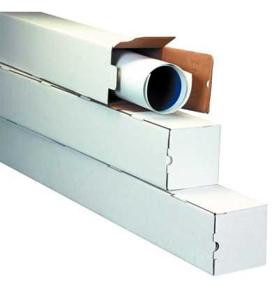
Mark, There have been past discussions. And I learned about my primary method there. One of the frustrations of web style is that it makes source attributions difficult. Actual names are not often used. Jobs, promotions, grant money, and invitations to speak are not at stake, the harm is slight. Footnotes are difficult to use. Pulling bits and pieces together, It may serve to have some understanding of the physical forces involved and match a storage method to its likely interaction with them. Seasoned wood is essentially wood that is equilibrium with its environment of water. The volume and volume to surface area affects the time it takes. In an environment with controlled temperature and humidity, once at physical equilibrium, shape of wood should stay stable. You do not address your home's humidity. The literature of your island suggests that the humidity there fluxes, and is frequently at atmospheric saturation or even above. There is a constant dynamic at play with stored wood. Looking at the end grain of a plank will predict some of the forces affecting the shape a plank will try to take. Quarter sawn stock has the grain at right angles. This the more stable conformation. It is also more expensive. There is higher waste, and more labor involved. Flat sawn wood is a quick and dirty and the most common method used. The grain of a tree is a series of ever increasing diameter concentric rings. The end grain is most often at an angle. The worst of the effects involving a plank changing shape from the desired rectangle, is when the center is involved in where a particular plank comes from. If the end grain is not a series of parallels, if they mirror each other, there is a tendency to draw the edge towards each other. Trees taper in overall diameter and they often rotate in a cork screw fashion. The forces involved with changes of shape are more when the water content is high. - Twist and cup are particularly troublesome during the seasoning process. Kiln drying often can get the water out before the wood can reach the shape that internal forces demand. Hydraulic pressure can be strong. The changing water content in a dry plank bring it into play. It will overcome less than adequate counter forces. Kiln drying or drying under a weighted stack may leave internal stresses that take every opportunity to release. This is a part of the playing field. Storage of drying wood requires adequate air flow around each plank to get the water vapor away and not support the ever present fungus. Wood in equilibrium does not need air flow for drying. I am imagining that a thick stack of closely packed wood, that has been stored where there is no humidity control, will need a little time to equilibrate with the build environment. POF requires a large supply of wood. Using a suggestion here I use cardboard mailing boxes. 2' lengths are convenient for me. Aviditi Square Mailing Tubes, 3" x 3" x 25", 25 Each per Bundle (M3325),Oyster White Also 2" x 2" x25" The contents can be packed. Laid flat, they stay where placed. 2' long is a pain to find floor space for. Mailing tubes, paper towel roll cores, and egg crate dividers in a big box, make for easy storage of a size sorted stock. They work best when stood on end. Gravity will pull on the top of the planks and bending is a frequent result. None work well when flat. The box dumps its contents. The tubes roll and their cross section is a circle. Planks are rectangles. The fit is less than optimal. I know of no pat solution. Mostly it is a matter of applying finds to your situation. Give a thought to what Nature is trying to do to the wood and see if your proposed method offers an adequate counter. About your present stock, forcing it back to flat is good for stock being feed to a tablesaw. The product of the saw will possible not warp significantly - depending on size. The reshaped plank will continue to seek its preferred shape over time. If you use it on a model, the bond and fittings holding it in place must be stronger than the natural internal forces if things are to stay where you wish them to be.
-
Converting a Backyard Shed into a Model Workshop
Jaager replied to Hank's topic in Modeling tools and Workshop Equipment
A dining room style backed chair with a cushioned seat is worth a thought- for where is done, the constantly in one place, watch repair type work. A backless stool (or two) with big and at least 5 rollers and easy height adjust. Even with 5 rollers, take care where you place your butt. That is unless you wish to practice for a role in a "Help! I've fallen and can't get up." commercial. Those suckers will flip you in an instant. This is not theory. Home Depot sells craft size pieces of 1" Styrofoam ( starfone in KY ) insulation. Cut two brick or a bit larger blocks - that are the same size. PVA glue them together and to a piece of 1/2" ply that has an apron on the four sides. Poke deep holes in the top to fit hand tools. Things like pin vise drills , Kelly clamps, scissors, Sharpies, knives, pencils, small hammers,... keeps them to hand, but off the bench top. Hot melt works more quickly - is a knee jerk thought, when quick is the only consideration - you really do not want to use hot melt on Styrofoam. -
A DIY thickness sander
Jaager replied to Kris Avonts's topic in Modeling tools and Workshop Equipment
Kris, About your thickness adjuster - The ideal situation is one degree of freedom. You may be challenging precision too much with 4 degrees of freedom. Theory, and shoulda, and oughta are sometimes at loggerheads with how it really is. Keeping the table the same distance from the roller along the entire width/length can be a challenge with any design. I advise verifying at the extremes and in the middle. -
A DIY thickness sander
Jaager replied to Kris Avonts's topic in Modeling tools and Workshop Equipment
Kris, Long ago, there were plans for a DIY thickness sander sold by the guild. I built a machine using the plans. It had a Maple drum. I paid a wood turner to make it. The blocks of Maple were glued with a 1/2" steel rod in the center. The final size was 11" long with a circumference just at 9". The sanding media available then was 9x11" paper sheets. I never mastered a technique to have a mechanical paper attachment, so it was a chemical adhesive. Things about it that I would do differently - Drum = Make it 12" long - there is cloth backed media here that is 4" wide. I could have 4" 80 grit, 4" 220 grit, 4" 120 grit. With mine, I had to trim 1" off of the 120 grit. I had trouble finding a practical adhesive. Contact cement holds well, but is difficult to undo. I think that using what I use for my 5" disc sander would do - rubber cement. Motor = use a 1/2 hp instead of 1/3 hp motor. Still make it 1700 rpm for the drum. Faster burns the wood. I see no advantage in it being slower House = Never enclose the motor. I did and having the motor in an oven is a poor design. Have as much air circulation as possible. The Table = here I did OK -- 3/4" AA hardwood plywood. All 4 edges have Aluminum right angle attached with more than a few, longer length screws - recessed heads. Longer on the front and on the back is a good thing. Now, the most important component - These machines can generate impressive amounts of wood flour. The size is small enough to float in the air and is readily inhaled. I made a five sided box to sit over the drum. It is made by glueing three layers of Amazon box cardboard together using libral amounts of yellow PVA for each side. The inside corners are strengthened with a 1/4"x1/4" Pine stick - 8 sticks . The top has an female attachment for a 2 1/2" shop vac hose. The inside of the top has Pine stick glued to accept the screws holding on the vac attachment. The outside is covered with high quality duct tape. The cheap stuff has poor adhesion. If you think that you do not need a cyclone in line trap between your machines and the vac motor filter, while that may fly for most machines, this one is in its own class. The volume of saw dust is not to be believed. Without the trap, much time will be spent clearing the vac filter. The 5 gal cyclone catch chamber will need checking more often than is imagined. Because of these machines, having a N-95 mask was no problem for me. A cousin who is a house carpenter, had to have surgery to remover a sawdust bezoar from his sinuses. He avoided using a mask because it fogged his glasses. Real world saws have TPI that produce comparatively large sized dust. So even the relatively coarse sawdust that does not get to alveoli can cause a problem. 220 grit can get down deep. ---finer than 220 grit is not a good idea anyway for stock wood surfacing. Too fine a surface and PVA has no tooth to bond to.
