


Jaager
-
Posts
3,084 -
Joined
-
Last visited
Content Type
Profiles
Forums
Gallery
Events
Everything posted by Jaager
-
If interested in function over cachet - there is an older plastic gauge. It is $6 @ Peachtree
-
 I just placed and received a five book order. The web site did not provide me with an confirmation and I did not receive an email. I saw that my credit card had paid the bill - so I wanted to see if the order had gotten thru. I can't use any website's " contact us " link - it starts an endless loop of new tabs - hundreds of them if I let it. I sent an email to the address from a Google lookup: gmail = seawatchbooks@ no reply so a couple of days later I found an address from an old order seawatchbooks.com = customer_service@ I got a return message saying that the order was shipped and since that was yesterday and it was here today - my email was not involved. The curious part was that the reply was from a gmail account. Try both email addresses - I can't say which worked for me.
 -
On a band saw, another way to work unstable stock, like a warped board or a log is to fix it to a carrier plank and sacrifice part of it at the fence along with the stock. Or, if the subject piece is not too wide have the fence far inside as well as the carrier and have the stock overhang and only it be cut. Framing brackets and drywall screws can produce a rigid mounting. system. I don't have a jointer or edger. Perhaps if I had been interested in cabinetry or furniture making.... Although unsaid, you are right about a thickness sander taking a whole lot of passes to work down seriously marred stock. Hours of really boring work. Roger, how do you control the sawdust? I made a open bottom box with a 2.5" hose connector on the top to sit over the drum. I made the box using three layers of Amazon box corrugated cardboard - using a liberal layer of Titebond to bind them and 1/4"x1/4" pine sticks reinforcing the inside corners. The volume of dust was tough on the shop vac until I added Dust Deputy cyclone trap inline.
-
At 3 inches, it would fit a Byrnes thickness sander just fine. I predate that machine at all this, so to get that type machine required building my own from NRG plans since lost. I sized the roller to take 11 x 9 sheets. Now, I would make it 12 x 9 - as the Klingspor cloth backed media that I use comes at 4 inch width, I mount 80 grit and 220 grit and trim off 1 inch from 150 grit. The 80 gets the most work. I would also not enclose the motor compartment now - just the sides - motor heat wants air circulation. I do not have an edger, but I plan to use a fence on my drum sanding table and maybe use a Microplane shaper, if not 80 grit on the drum. Usually I waste the first pass thru the table saw ( a Byrens machine now). If it were my stock, I would not wish the loss a blade thickness machine would produce. I like 24 inch length for my stock, I would find 36 inches a bit cumbersome.
-
What is the scale that you build to? for which parts will you be using this stock? A power planner = a smooth surface but at a significant cost in lost material ... ~1/8" or more per surface. There are sanding planners that can take wide stock, but I am thinking that they are limited to large shops - the machines are expensive and the cutting medium is also expensive. The size of thickness sander that we use limits the width of the stock. It saves on how much stock is lost to get a smooth surface. It just takes a lot of passes, at a cost of your time (and lungs if you do not sequester the dust) . I would use the raw stock as you have it now to reduce further. I think that resawing is one of the more challenging operations. A table saw can get you a smooth enough surface, for minimal finish sander passes, but the kerf loss can add up, and that thing is just waiting to eat your fingers. The blade is less prone to wander - so you do not have to adjust between passes as much -( flipping the board if it is cutting a wedge.) A band saw is safer and the kerf loss is much less, the surface is rougher and takes more passes thru the thickness sander. A low kerf Woodslicer blade yields a smoother surface, but it costs more and the Boxwood is hard and will dull either a bandsaw blade or eventually a circular saw blade more quickly than most wood species. With rough stock, it can be tricky with the raw face against the fence and it is a coin flip for whether to do a thin sacrifice for the first pass or do a standard cut and know that it will take more thickness sander passes and come out below spec and have to be used for another part. For badly cupped boards - cut down along the crown of the cup - and get two flatter boards. I buy rough stock. It is more work, but knowing that a 4 sided finished board sold as 1" is actually 3/4" means to me that 25% has already been lost before I start. Sorry for the following, as it does not help you: I would have cut the log into 2" planks and some 1". I do POF and the stock cost for framing timbers far exceeds that of any other component. I build to a larger scale = 1:60. It is close to 1/4" scale but at 1/2 the volume, a model is less over powering in size. ( But, the first rate I just got in frame is still giving me pause - 4 feet is still a lot of ship.) I band saw the 2" into stock for my thickness sander to get 2" wide planks that are the thickness of the frame timbers. My game is to find the band saw cut thickness that will yield a finished two sides without extra passes. It does not matter that the vertical edges are rough - i just fudge the frame patterns in a bit). I imagine that at 1/4" - the pattern placement might yield more stock lost to waste, but I get fairly efficient yield with 2" at 1:60. My band saw is only 3/4 HP and 2" works it enough.
-
I am guessing here, but what ever the angle of the rabbet is for the garboard to fit at the dead flat - that would be continued fore and aft and the edge of the garboard trimmed back to match it. This would not really compromise the plank and would preserve the keel. Also, at the skeg, the deadwood was cut into for the bottom plank lands. In deadwood area aft as well as toward the bow, there is no advantage in a garboard that is thicker than the bottom plank. I have not seen any aft stations where the curve is any deeper for the garboard.. The ship builders were not the sort to do any more work than was necessary. The hogging stress was mitigated by the depth of the deadwood. A thicker garboard would = insignificant additional strength, and a lot of pointless work and material cost.
-
I don't know what to say about that rabbet. I see it as weakening both the keel and the garboard. The upper half of the seam could not be caulked and it limits just how deep the oakum and pitch could go. If I were the ABS, I would want to do the experiment. In use, there would be a lot of movement and stress along this location. As far as the dubbing, that is from what was done at the wale. The 17th C there was a step function between it and the bottom plank - on either side. This evolved into a smooth transition from below and a step function above for a time. By the 1850's the transition was smooth both below and above, That there was a wale is not obvious.
-
A wedge was not cut in the face of the garboard edge where it meets the keel. The right angle face was kept. The angle of the rabbet was adapted to meet it. Thus, unlike on the plan, it was not a fixed dimension internally. This will fix your too deep notch at the top of the keel. The object was to provide a space for caulking the seam, without there being an acute angle to chip off on the garboard. There would be one if the keel were kept intact and the face of the garboard was trimmed to mate it. In a fully planked hull on a model, which face is trimmed does not make much difference, since it is hidden anyway.
-
Yes, and it looks better than I imagined. The hollow effect actually matches a memory I have of a similar situation.
-
I would change the angle of the rabbet to encompass the full garboard thickness. Since the position of the surface of the frame is hidden when planked, I think that the adzmen would only dub the proud outboard corner of the diminishing strakes off. The resulting smooth surface would be a slope that is a bit more eccentric than the curve that you have plotted.
-
It was a typo - 8-7-6-5... What I mean is that - say that you have defined 3 regions (using battens) between the bottom of the mail wale and the top of the garboard plank to totally plank the hull. In one of the regions - you decide that a run of 8 planks meets the max/min plank width ideal. You measure the opening at each frame (or mould/buulkhead if POB) Use the fan to determine the 1/8 of the total for a single plank. Spill the strake and mount it. Now measure the opening and use the fan to determine 1/7 - spill - mount . measure -fan 1/6. ... You do not make up all 8 plank strakes at the beginning. It just does not work well to do that- there are too many variables. The fan as well as directions for planking- infinitely superior to mine - NRG home page to data to resources to database to planking and framing.
-
A batten is a temporary plank. In one era - in prep for a storm, hatch gratings were covered with canvas which was held down with wooden battens lashed to ring bolts on deck. "Batten down the hatches". When framing a hull, widely spaced bends (a pair of overlapping frames- measured and cut) had framing battens which ran horizontally from stem to stern and were used to both support the bends and act as a jig to help to shaping of intermediate bends and (mostly English) the filling frames. In models similar battens are used to find the sweet zones for smooth and attractive planking runs. A spilling batten is a thin flexible "stick" to connect the dots to get the full curve to cut to when spilling a plank. Spilling probably is a slang conversion of spoiling. Because a hull is a complex compound curve - rectangular planks will not properly cover. The width constantly changes. An expensive wider board is trimmed - usually on one side only - to fit the space. The waste wood is "spoilled" or later spilled. For the last plank to fill a run, if lucky, a rubbing on a piece of card or paper can define the needed shape. For runs of 9-7-6-5-... a fan gauge is useful to provide the points to use the spilling batten on.
-
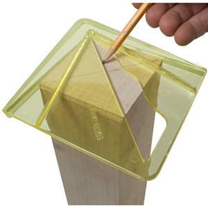
how "1. profile gauge " works? It is a stack of movable pins. Push it against a curved object and it duplicates that shape. One side is negative of it, the other is the positive. The present versions are plastic and the "pins" thicker. A potential use - getting a precise shape for the breast hooks for a close fit - gets defeated because most of these tools are too wide to fit inside a hull - unless a heroic scale such as 1:36 or 1:24 .
-
Quick and Thick Titebond glue problems
Jaager replied to Kurt Johnson's topic in Modeling tools and Workshop Equipment
I save a lot of the foam packing - both peanut type and sponge sheets. I use the pink stuff from Jim Byrnes to make custom glue spreaders miniature versions of disposable sponge brushes - using 1-3 round toothpicks and Duco cement (not much good for anything else - poor shear strength for me). Any Way - perhaps you can cut some foam as an intermediate to protect the piece for clamping. -
Quick and Thick Titebond glue problems
Jaager replied to Kurt Johnson's topic in Modeling tools and Workshop Equipment
Thixiotropic means that when still - it is thick and acts solid - when shaken - it is fluid. My guess is that it would be usful on a bond where normal PVA would flow off . Otherwise, I imagine a downside - more difficulty getting complete coating on both mating surfaces. If your Titebond II bottle is other than yellow cream in color, or has a strong acetic acid smell - it has deteriorated. My guess is that your surface prep could be the problem. PVA bonds by a chemical reaction - long cross linked chains. The surfaces must be porous. They must be close together. I do not use finer than 220 grit abrasive and I scrape with a steel edge on both faces. The scraping clears sawdust from the pores. Clamp as tight as can be had without crushing the wood fibers - Use a buffer of a softer wood species as an layer between the work and the clamp face. Ultimately, consider using an old school technique ( Underhill I think ) suspenders and a belt = glue and dowels. I clamp overnight or 8-12 hrs. I wait at least 24 before using any mechanical force on the area. -
Check SeaWatch books I do not have this volume yet, so I do not know if the plans provided include the standard 3 view lines My Smithsonian catalog lists lines plans in page 181. I also have TIFF and JPEG copies of the Webb originals on a CD from a member here SharingHistory.com as a bonus on J.Scott Russell's The Modern System of Naval Architecture 1865

-
Reducing extractor noise
Jaager replied to Williamo's topic in Modeling tools and Workshop Equipment
A side swipe lighting strike burned out the circuit board on my garage door opener and I have never placed it. I manually open the door and unlike most, I do keep my car in the garage - I live on The Bay - Little Creek harbor actually - the salt water could maybe rust my car. I do not mind the exercise. So I don't know if the frequencies are the same - and an ironic factor is that my car has the ability to produce the activation signal. I was hoping someone knew why the Festool will not run continuously. It acts as though the overheat protection control is set at too low a temp. It is not the RF switch. If it because of the cyclone trap ( the Wood Craft salesman said that Festool nixed a custom cyclone trap for their machines) then it really is an unacceptable machine. Pointless to test that since I will never not have the cyclone trap in-line. The clogged filter and quickly full bag with a vac only system = too much hassle.- 17 replies
-
- 3
-

-
- cyclone
- vacuum cleaner
- (and 2 more)
-
Reducing extractor noise
Jaager replied to Williamo's topic in Modeling tools and Workshop Equipment
I used an old Sears 16 gal shop vac for years - It was really loud - had to use sound suppressing head phones with it. When the motor started arching, I retired it to the dump. Following discussions here I bought a Festool Midi. Since I use a cyclone trap - the capacity of the unit is not important and the smaller foot print was an advantage. It is quiet enough, and pulls enough air, but it turns itself off after a short run time. A total waste of $600. Looking around, I found a Rigid 14 gal at Home Depot for $100 that is about as quiet. I no longer need the head phones. It stays on just fine. The only occasional problem = I live in a condo and I think at least one neighbor has a garage door remote that uses the same frequency as my on/off remote for the vac. I have to make sure to unplug it when I am done.- 17 replies
-
- 3
-
-
- cyclone
- vacuum cleaner
- (and 2 more)
-
First off: the glue space is determined by the clamping pressure used. But, way back when 17th C. Naval Board style framing was first presented as something we could do, the add-on effect of the glue space was speculated as having a measurable effect, since the timbers meet continuously fore to aft. Using a mechanical micrometer I measured the following: Titebond II 0.001" white PVA 0.0004" liquid hide glue -0.0013" not sure how this came to be The video instructions on the Gerstner & Sons site suggest that too much pressure can produce a "glue starved" bond. If both surfaces are coated prior to the join, with PVA, since it bonds by internal polymerization reaction, I do not see this as a problem. With older glues, such as hide or casein this could be a problem.
-
Gluing planks to a filler
Jaager replied to Peter Y.'s topic in Building, Framing, Planking and plating a ships hull and deck
Taking a step back and looking at this from a larger perspective, I have what is probably an impertinent question about the core of this inquiry. If there is to be a second (finish) layer of planking, why is a filler even being used? Is the next layer so thin that it follows every dip of the subsurface? If the planking is that thin, I would probably replace it with a more robust planking. A filler is meant to fill holes, not do what Bondo does in auto body work? Since it is being covered, looks do not matter. If there is an error with a significant hollow, I would scab a piece of wood veneer there and sand it to spec. -
Gluing planks to a filler
Jaager replied to Peter Y.'s topic in Building, Framing, Planking and plating a ships hull and deck
PVA - bonds by undergoing a chemical reaction as it dries - producing long and I guess branched chains. If the mating surfaces have pores or protrusions large enough ( I think 220 grit or more course) and are close enough together, the bond should be adequate. Most fillers seem to have a rough surface. As long as it is not brittle, or weak or does not have a glass-like surface, the PVA should work. If the surface IS glass-like, CA would work better. If the filler itself is weak, no adhesive can mitigate that. -
bending planks
Jaager replied to bluenose2's topic in Building, Framing, Planking and plating a ships hull and deck
You need heat to loosen the lignin bonds to bend the wood. Lignin is not affected by water. The water is to increase the efficiency of heat transfer into the body of the wood. A short soak, and just enough heat - it is not useful to burn the wood or scorch it even. A heat gun, a soldering iron (the old commercial bending irons were just a soldering iron with French curve metal attachment), or of late, we have colleagues who have done serious bending using a generic curling iron. -
L'Ocean - a Sane' designed 118 gun - launched 1790 as Les Etats de Bourgogne Gerard Delacroix authored a significant monograph of the lead ship of this class Le Commerce de Marseille The colors he provides for late 18th C. The same for the AAMM monograph for a 74 = Le Superbe 1785
- 2 replies
-
- 1
-
-
- french 74
- decoration
- (and 2 more)
-
Byrnes table saw blade for cutting planks
Jaager replied to genericDave's topic in Modeling tools and Workshop Equipment
Thru experience, I have learned that the cutting does not happen the way one might wish. The blade has to remove the wood that it cuts, This translates into - the thicker the stock, the fewer teeth and deeper gullet for the blade. The thicker the stock - the degree of set on the teeth has an effect on cutting efficiency. No set and a thin blade = smooth cut surface and less wood loss to kerf, but if can - the blade will burn the cut surface due to friction - will want to bind and may flex. With a selection of blades, for any stock thickness, the goal is to find the blade with the most teeth, lowest set, thinnest body that will cut without binding, burning, wobbling and unacceptable kickback ( it hurts getting hit in the belly with a piece of thrown planking.) Start with the most aggressive blade and work to the finest that will work. Unfortunately, the slitting blades are pretty much limited to doing just that, making grating mortise and such like. -
First we define the terms and scales. 1:96 or 1/8" = 1' is a semi miniature scale often used in ship modeling although it is 1/2 museum scale (1:48) in any one dimension - the final subject - being a 3D construct is 1/8th the volume of a museum scale model. It is difficult at best to try to be precise with scantlings in miniature scale- how it looks to the eye is more important. Under rather than over works better. HO scale is 1:87 It is about 10% larger than 1:96 You have not stated your actual scale for your model. With your 7" value - I was thinking thickness, but a contemporary liner would be 4" thick on the main gun deck - so width it is. the outside limit would be 10" - 1/16th inch is 5.4" in scale . At 1:96 that is going to look "busy" for plank width. Get the 1/16" - but use that for the thickness. Use a steel straight edge and VERY sharp knife blade the slice off the plank width from that. Given the small scale involved, the most I would recommend as far as caulking rep is to add a slight walnut dye to the glue at the plank edges.