


Stockholm tar
-
Posts
866 -
Joined
-
Last visited
Content Type
Profiles
Forums
Gallery
Events
Posts posted by Stockholm tar
-
-
Jan,
Dafi is correct. The ringbolts were normally positioned as near to the centreline, behind each gun, as was possible. This would give the tackle the maximum amount of room to operate and be effective. However, depending on the gun's position, I am not sure that the guns always entirely cleared their ports, and there are instances of the rammer and sponger having to operate with their implements out of the port. Incidentally, the gun's own recoil would normally return it to the loading position.
Regarding the entry ports, Goodwin in his 'Construction and Fitting of the Sailing Man of War', says that they were fitted between 1660 and 1810, although some ships continued their use after that date. That is presumably why early 20th cent. photos of the Victory show her without an entry port. He also states that the first use of entry ports, port and starboard, was from 1671.
As to their use, I think Mark is right, and that they were for the use of senior officers only. I may be wrong here, but I'm not sure lowly mids and lieutenants would have been allowed to use it, unless they had special dispensation.
-
Ira,
In my experience, a gaff has both throat and peak halliards on vessels of any size. I have heard of single halliards for both purposes on quite small boats but, as has been said, to get any fine adjustment you need both. Your vessel is a topsail schooner, thus pretty sizeable, so I would think she would have had both throat and peak halliards.
I know that when I used to sail on gaff-rigged vessels, the gaff was usually hoisted horizontally until the luff (the leading edge) was at full hoist, at which point the throat halliard was belayed. Then the peak halliard was sweated up until it was at the correct angle, when it too was made fast.
-
Jeff,
Looking very good. I particularly like your deck planking.
-
Jeff,
Looking good so far, and it's probably a good idea to paint various parts before installing them, when you then can't get to them easily – like the frames.
Btw, have you any of the books on the Victory, that you might use for reference. They might help the rather poor instructions (nothing new there).
-
Hi Jeff,
I shall be following this with interest as I too am building this kit – although it is on hold at the moment whilst I finish my present build, the cutter Sherbourne.
Like you I agree that it is an interesting model, and that the interior as built is rather dark and drab, so I intend to paint a lot of it white. I am also thinking of some interior lighting. I intend to do quite a bit of kit - bashing, which I hope will improve it considerably, by fitting out the various decks as close to the actual ship as possible. Leaving off some of the planking on one side might also be an option. I have also decided to extend the length of the model by adding an extra frame, which will make her end at the break of the fo'c'sle, and am thinking of giving her a full-height foremast (the latter necessitating the former, to accomodate all of the shrouds and backstays). I have even thought of making her a waterline diorama (!) partly to do away with the rather awkward stand, but I shall have to think more about this when I resume work on her.
I am not too happy with many of the fittings supplied. For instance I think the figurehead is very poor, and the guns I will probably replace. I also believe there are rather too many pillars shown on the plans – and some are actually in way of the guns.
Anyway, enough about my bow section. I hope yours goes well and, as mentioned, I shall be following with interest.
-
Sumner,
Wow, you certainly live the high life. What a view – perhaps not so good when it's raining though!
Very neat planking job on your Sherbourne, well done.
-
Tony,
Good point about the port lids. I had never heard of them opening wing fashion on cutters and, as has been mentioned, would have thought the ones next the channels wouldn't have opened fully – thus rendering them in line to be demolished by her own gunfire! The only split lids I have seen have been on frigates, in upper and lower halves.
The whole question of fitting lids seems to be rather hazy, certainly for cutters of Sherbourne's date, and most don't show them. As you say, the lids on the rather later Science Museum model (dated 1785) and of the normal upward-hinging type, are the only ones in the book. Alert herself doesn't appear to have been fitted with them, and the photos of the Hawke show a similar open rail.
Sumner, like Jay, I'm waiting to see your clinker planking!

-
Jay,
Sorry you have been ill, and hope you are better now.
I'll see what I can do about Bluenose. She's a little dusty right now, and will need a bit of a going over with a paint brush! Also one of her nav. lights has come adrift and will need fixing. Then I'll try and take a few good pictures of her.
-
Hi Sumner,
Your Sherbourne's looking very good so far.
I like your stern planking, and I wouldn't worry too much that they won't be visible when painted. I think it largely depends on how thick each paint layer is. If you keep each coat fairly thin, with good overall coverage, I would think you will be able to see the planks when done.
The carvel laid painted planking, on the upperworks of my Sherbourne, are still perfectly visible.

-
-
When a ship sinks by the stern, is that how we get the expression 'heads up'?

Mobbsie,
Especially for you: http://en.wikipedia.org/wiki/Poop_deck
Popeye,
Sorry about that, and of course you can call it whatever you have a mind to. I seem to remember that when I had the chance to saile on ye Golden Hinde replica several years back (and more years ago than I care to remember) the crew called it by a few other choice names as well!

-
Paddy,
Yes, as you suggest, it's probably best to concentrate on your Triton cross section, rather than starting on Sherbourne as well. Having seen your Triton log and your attention to detail and neatness, I think it's going to be a first class model. When it's finished, I imagine Cheerful will be ready and you can then go straight on to her.
John,
Thanks for your input. Yes, I thought it would be something like that and, as you say, the anchoring techniques on the earlier cutters would very likely have been much the same. I imagine the cable on the later nineteenth century cutters though would have been chain?
-
Paddy,
Yes, I used the cannon that came with the kit, although I wasn't particularly happy with them. Some had an amount of flash to clean up, and a couple were a little misshapen at the muzzle end. These two I turned so that the damage was not so visible! Neither the barrels nor the carriages were that accurate (for example, the barrels don't have all the reinforcing rings) and thinking about it now, I probably would have changed them.
One point about the guns though, was that I had problems in getting two of them to fit through the ports (my own fault for not getting one of the gunport strips really straight!) and it took a quite bit of sanding, etc., to get them to do so (and even now they almost touch the top edge) so you would have to find some approximately the same size.
As to whether Chuck's guns will fit the Sherbourne I'm not sure. Perhaps you should download his pdf and check, or send him a pm. I note though, they would appear to fit his Cheerful.
I suppose you could build the Sherbourne in the interim, whilst waiting for the Cheerful. As I say, she is a nice model to build, and you can have fun improving her, but I would think that Chuck's cutter would be the more interesting and accurate. I would like to see you start that when available.
I found Peter Goodwin's 'Naval Cutter Alert' to be very useful, particularly for the earlier cutters like Sherbourne (Alert was fourteen years later). One thing I did find slightly annoying though, was that the belaying points for much of the running rigging is omitted, which often left me wondering where I should belay various lines. I have Petersson's 'Rigging Fore and Aft Craft', which is of some help as it contains the rigging of a cutter. However, this vessel is some twenty years later than Sherbourne, so discretion is advised.
I hope this helps.
-
-
No thanks necessary gentlemen, only too glad to help if it results in Paddy finding his model.
Paddy,
It would seem as though you're veering towards the Sherbourne then, rather than the Cheerful?
Jay,
Ok, not from C.C, but it looks as though it might have been. Thanks for the link, I shall look at that with interest. Those cod schooners were fine ships, and probably prompted me towards my first model, although I opted for building Billing's Bluenose ll. At 100th scale, she is a bit small though. I finished her some years ago now, but was actually thinking of putting photos of her in the gallery. I replaced all the plastic parts with wooden replacements, gave her propellors, and used Jensen's book for the rigging – so I was kit bashing even then!
-
I can just here one salt to another:
'Wot... no ratlines? How're the sailors to get 'upstairs' then?'
Sorry Jim, but if she's supposed to be a model of a historic ship, then ratlines come 'as standard'. The best way to do them, is to tie a few at a time, then do something else (either on the model or elsewhere), and come back to them later.
-
Another conspiracy theory... and does anyone else think his solutions seem just a tad simple?
-
Jay,
Thanks for your continuing interest and kind comments. I'm flattered (flattened?) by your words, however, I fear that's a little over the top!
Having said that, I think such comments make us all better modelmakers, and make us strive to do the best job we can.
No, I certainly don't mind you offering advice to Paddy re. Jotika/Caldercraft suppliers in the US. I hope he finds what he's looking for.
Btw, is your avatar a still from Captain's Courageous? I love that film.
-
-
Popeye,
Thanks for your kind comments.
Thanks also for your input re. the anchor/windlass. I'm sure John might also have a few insights.
-
Sumner, TK11,
Thanks for your comments.
Jud,
Thank you too.
As to your question, I'm not exactly sure – apart from the strain put on the windlass from the anchor! The windlass, which was normally fitted on small vessels, was itself used as the riding bitts – unlike on larger ships, which had separate fittings. From what little I have read on the subject of windlasses, (it's mostly about capstans) there were various methods to prevent the cable from running out accidentally, including using various stoppers, and the fitting of capstan bars on the fore side of the windlass close to, or touching, the deck as a precaution against its running back. The anchor was of course normally securely lashed. Probably the best precaution however, was a well trained crew – and any seamen would know of the dangers associated with anchors.
Before 'letting go' in the normal fashion, I would think that the cable was detached from the anchor, the turns were taken off the windlass and the cable flaked on deck, before the cable was re-attached and let run under the windlass. Of course the cable might just have been allowed to run off the windlass.
I have sailed on a few sailing ships, but have never come across a windlass. They seem though, to have been used on small craft into the twentieth century.
Perhaps John might like to comment?
-
-
Thanks guys,
I appreciate your continued interest.
Eamonn,
Sails on models are a probably a personal thing, and I (like you I imagine) don't particularly like the sails set when a ship is on a stand. However, I think furled sails are acceptable, as not only do they allow more detail to be seen, but they give the impression that she might be going somewhere – if only she wasn't fixed to this bit of wood! Many here won't agree with this view, but each to his own. I'm flattered that you might emulate my example.
My apologies for the 'missing' pages to my log, but I'm afraid I can't remember that far back!
BE,
Thanks, as always.
Paddy,
Thanks for your kind words. She is indeed a 'grand little kit' as you say, and is certainly open for improvement. I don't believe you however, when you say you couldn't do her justice, as I am certain you would make a fine job of her. I don't know if the Sherbourne, or any of the other Jotika kits, are available in the US through an agent, but I hope your searches bear fruit.
-
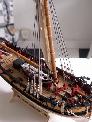
Having fitted the boom, the next job was to make the gaff. This was made in a similar fashion, its dimensions being taken from the AOTS Alert book. The gaff tapers rather more along its length than the boom, with its maximum width being closer to the mast. Again, I made similar modifications to the kit-supplied jaws (they are actually the same fitting as for the boom) in that they were first split in two, each half being shaped to fit the gaff end, and then glued to the spar on either side.
The other fittings are as follows (from the jaws end): an eyebolt on top of the spar, just above the jaws, to take the lower double-block of the throat halliard; a stop, on top of the spar, just aft of this to retain the mainsail throat lashing; a strop for the small double blocks (one each side) for the mainsail brails; another strop, fitted about midway along the gaff, to which were attached two small single lead blocks, again for the brails; two stops on top of the spar, for the rigging span to which is attached one of the single blocks of the peak halliard tackle; further aft, a strop for a second single block for the peak halliard tackle; at the after end, a stop to retain the mainsail peak lashing; finally, an eyebolt in the end of the gaff to which is fitted a small single block for the ensign halliards. I decided to paint the entire gaff black, including the jaws, and gave the spar a light covering of beeswax.

I thought there might have been similar problems of movement with the after end of the gaff, as there had been with the boom. However, having dry-fitted the spar, in its hoisted position on the pin inserted in the mast, I found it was quite firm and that further measures were not necessary. I also surmised that the process of gluing would significantly reduce any movement. Due to this concern, I had initially intended to fit vangs at the end of the gaff, made fast to belaying pins on each quarter – but then discovered that these items of rigging weren’t fitted at that date. There is, therefore, a spare belaying pin aft on each side. I had a slight worry that the pin in the aft side of the mast might not be dead centre – or the end of the gaff would be off to one side or the other – and it was just slightly out. On the real ship it wouldn’t necessarily have been all-square in any case.
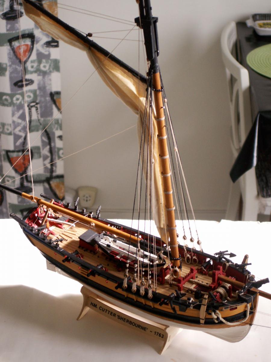
Having decided that it would be best to lace the gaff to the head of the mainsail before fitting the spar, I now set about making the sail itself. This was cut from an old, thin, handkerchief, its size being about half that of the actual sail area in order to reduce its bulk when furled. Naturally I made it with a full-length head, to be laced along the length of the gaff, narrowing towards the foot. To represent the seams, I teased out equidistant strands from the cloth, about a centimeter apart, which seemed about right. The operation had to be done very carefully, as the strands could break quite easily, using a pair of tweezers. Around the sail’s edge I made a narrow hem, using a fabric glue, to which I added a scale boltrope (on the traditional larboard, or port, side). I then added reef bands and reef points, with strengthening pieces at the peak, throat, tack and clew (I now realise that those at the peak and throat are a little over large, something I will have to watch with the other sails.)
Then it was time to put the kettle on. When it was reasonably hot, but not boiling, I poured the water onto a teabag – for staining the sail, of course (!) – in one of my wife’s small baking trays. When the resultant ’brew’ was about the right colour I put in the sail, spreading it out so that it was completely submerged, and left it for a couple of hours. As the sail changed colour quite quickly, I had look at it every now and then to see how it was progressing. Removing it from the tray when a suitable shade, I spread it out to dry overnight. When dry I found that, besides being a good colour, the cloth had puckered somewhat – which made it look even more realistic.
Now I had to attach it to the gaff, for which I used a needle and .25 black rigging cord. Fastening the cord around the spar at the jaws end I proceeded along the length of the gaff, piercing the sail just under the bolt rope (approximately every centimetre) with the needle, and forming a marline hitch along the spar as it progressed. A brief smear of glue under the line fixed each hitch around the spar when tightened, and a little touch-up with diluted black paint covered any excess that was visible.
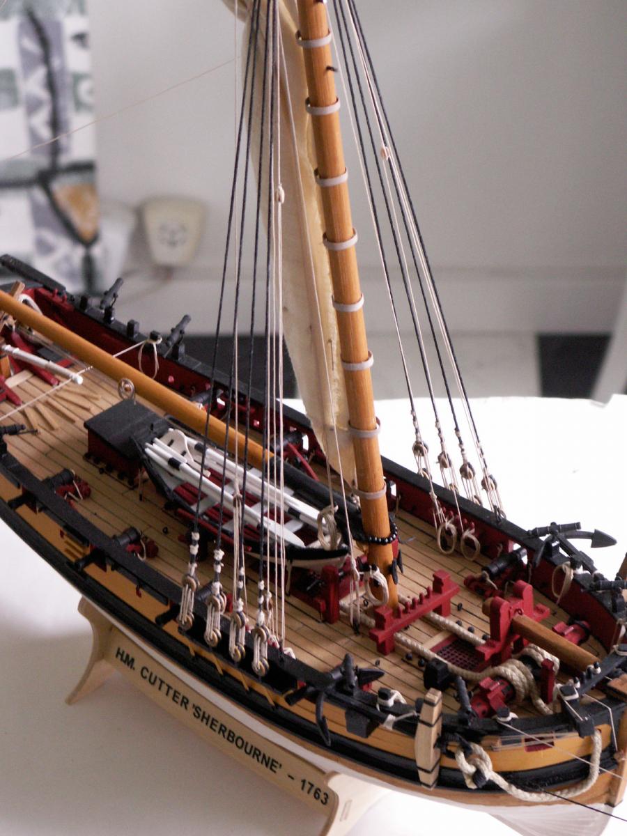
The next operation was to attach the gaff to the mast. As mentioned the spar was quite firm when dry-fitted, but the CA glue applied to the pin prevented any real further movement. I then fitted the parrel, in similar fashion as for the boom. With that done, the next task was to stretch out the luff, or leading edge, of the sail and lash the tack down to the eyebolt in the boom, using the loop I had formed in the boltrope. This stretched out the sail, and I could then concentrate on fitting the sail hoops. As I mentioned earlier, I had unfortunately already glued the crosstrees in place, which meant that I would have to fit the hoops around the mast. This suggested that they would have to be of a bendable material, and copper strip presented itself as a workable solution – some of which I just happened to have. Making the hoops was straightforward although, being a soft metal, it was quite easy to bend the strips out of shape if too much pressure was applied. There are eight hoops in all and I eventually worked out, with a bit of trail and error, how long they would have to be, including the overlap for glueing the ends. I seem to remember a high-tech piece of string came into the the process! They also have to be a loose fit, to give the illusion that they could run freely on the mast. Following a little experimentation, I finally painted them a near buff colour, which I thought suitable to represent wood. Being metal this took a little while, as there are about three coats, which also included those inside each hoop so that no copper was visible.
I fitted the hoops by cutting small equidistant slots in the luff of the sail the width of the hoop, carefully bent each just enough for it to pass around the mast, pushed one end through the slot in the sail, and then closed it against the other end, fixing it with touch of CA glue.
Furling the sail into the mast, which I had decided would best be done on the model, had to be attempted rather carefully. First of all I attached the two brails on each side, which I would actually use to furl up the sail, threading them through the blocks already fitted. Dampening the sail, with a light wetting from a spray bottle helped with the process. Then it was just a case of gently pulling on each of the four brails, two being attached to the clew and two at about the middle of the leech, and lifting the sail from underneath until it was as close in to the mast as was possible. During the process I was careful that the sail furled with a natural look, and that the folds hung evenly. When it was dry, I was quite pleased with the result. The brails falls were made fast to the pins in the boom jaws, each one being finished off with a small coil. It then only remained to belay the clew outhaul to a cleat on the boom, glue down some of the reef points (which stuck out at odd angles) to the sail, and the job was done.
Next time: More items of running rigging, the shrouds.
- Blue Ensign, Paddy, bhermann and 4 others
-
 7
7

Sherbourne by Stockholm tar - Caldercraft - 1/64
in - Kit build logs for subjects built from 1751 - 1800
Posted
Anja, Dirk, Kevin,
Thanks for your Birthday wishes.
I'm sure I'll have a great day – and I'll try my very best not to party 'tooooo' much.
As they say, one year older, another year wiser. In my case I'm not too sure about the latter observation.