


Stockholm tar
-
Posts
866 -
Joined
-
Last visited
Content Type
Profiles
Forums
Gallery
Events
Posts posted by Stockholm tar
-
-
Doug,
Really first class work on your Supply. Very neat. Looking forward to more rigging!
-
Hi Spencer,
Yes, you could look at it as a sort of pulley system for the shouds. The shouds are in pairs, the lower being fixed to the ship's side, the upper to the lower end of each shroud – and a lanyard reeves between them, connecting them together. Each deadeye has three holes, so there are effectively six lines per shroud, making for a very good support.
The beauty of deadeyes is that they can be taken in or slackened off, as circumstances permitted, and the shrouds set up as required. At sea natural materials, like hemp, are affected by the weather and humidity, and they behave accordingly – thus the ability to tighten up the shrouds, or conversely slacken them off, was a definite advantage. The crew, especially probably the bosun, were always alive to this movement and would watch for it.
Sometimes the shrouds were eased off for other reasons, such as those on the lee side being slackened off so that the yards (especially the lower) could be braced round a little more.
This ability was largely lost when bottlescrews came in, but then the rigging was usually of steel wire.
-
Moo,
Looks like you're off to a good start, but as has been said – patience, don't rush it. You'll turn out a much better model as a result. Asking questions here certainly will help. Personally I'm interested in seeing how she differs from the Sherbourne, that I'm working on.
The materials look good from the pictures, can you say something about the quality?
-
Michael,
I'll send you a PM.
-
Michael,
I say again – I thought you might!
Well, well, small world. I also know Bournemouth well (although I'm not sure I'd recognise parts of it now), as I went to college there when I was younger, although I was mainly at the Boscombe part of the college. However we sometimes visited the Lansdowne buildings, mainly for sitting exams! After leaving college, I worked at Poole Maritime Museum for eighteen years, and lived in Parkstone. I didn't know of the drawings that Bournemouth University drew up for the Pommern, but I remember the beautiful ones they did of the Warrior.
Yes, the Åland Islands are delightful aren't they? I agree too, the museum is one of the best of its kind. I must go back there.
I also agree the Viking serves some good food, but most Swedes probably wouldn't baulk at the cost! They keep her up very well, and when I was last in Gothenburg in 2010, she looked spick and span. It probably helps too that they have an active organisation to run her, and I have the feeling that many of them are old seamen. Yes, I agree, it's a bit sad that she has little running rigging, but I think this is because of maintainance and the cost of her upkeep.
Gothenburg is probably more of a seaport town than Stockholm, which has of course the af Chapman moored opposite the Royal Palace, and is used as a youth hostel. The ship was given a refit one winter a few years ago, at a yard south of Stockholm. The yard they used is completely undercover, being hollowed out from solid rock, and was used by the navy during the cold war period. Naturally the ship had to have her masts and yards removed, but she was given a thorough overhaul, and is now back at her old berth looking resplendent, and good they say for around fifty years.
Good story about the Stockholm police, although these days many local Swedes don't quite see them in the same light!
-
Nils,
Thank you. I'm quite impressed with her myself!

-
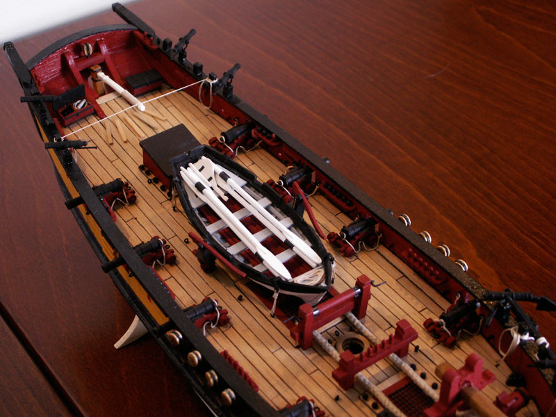
There are a pair of belaying pins in the small rail situated on the port and starboard quarters. Originally I provided these for the (lower) spread yard braces and the gaff vangs – before I discovered that vangs, at least on cutters, had not then been introduced. Thus the forward one is now a spare. There is also an eyebolt on each rail for a lead block, through which the braces will pass before being belayed.
Moving forward, on each side of the companion I provided shot garlands for the 3pdr guns, and these are also situated on each side of the other hatches. Garlands are also fixed to the bulwarks, between the guns. The aftermost, between the last pair of guns on each side, actually contain only three balls – and one belaying pin. This is to belay the falls of the running backstays, when they are rigged. The balls themselves are made from the round parts of a cheap necklace, which just happened to be the right size – and are definitely surplus to my wife’s requirements! Each ball was cut from the chain, tidied up, painted and then glued in place. (Btw, I usually use a thin stick with a small blob of blue tack on one end, to lightly pick up and glue small objects like this. I find it works quite well, and one can place items rather more accurately than with the fingers.)
We now come to the guns, which I have mentioned before as having caused a certain amount of trouble with relation to the ports! For each gun I provided a pair eyebolts in the bulwarks to take the breech ropes, another pair for the side tackles, and one in the deck behind each gun for the running-in tackle. The latter, of course, should really have a ring through it. I decided not to rig the side or running-in tackles, which perhaps was an ommission and, again with hindsite, I think the breech ropes are not really thick enough. However…

Each of the hatches was given a coaming, this being caulked into the surrounding planks and raised a little above deck level. I decided to fill in the hatches themselves with offcuts from the kit and paint them black, before fitting the red gratings, to give a sense of depth. This seemed to work reasonably well, the main hatch in any case being largely hidden by the boat.
We now come to that aforementioned very necessary item of equipment – without which, no vessel is really complete! I copied a suitable drawing, from ’The Boats of Men of War’ by WE May, which was about the right size that I needed. The boat was constructed on a small building board, with scale frames and planking, the latter being mostly card since it was much easier to work and shape. The gunwale, which is made from wood, has rowlocks cut in it. The interior was then fitted out with thwarts, resting on internal stringers, sternsheets, and a small foredeck. The inside was painted grey, and fitted with bottom-boards which were painted red. This I thought both made for a nice contrast with the main interior, and also matched the red of the cutter herself. I painted the outside the same ivory shade I had used below the cutter’s waterline, and the gunwale is black. To finish off, the oars were made from orange sticks, with thin card for the blades, and painted white. Thin black paper made suitable leathers. The rudder was made from thin ply, with a wood rudder stock, and there is a separate tiller. A coiled painter was provided on the foredeck. The boat was lashed down to four ring bolts in the deck.
On either side of the boat are the pumps. I modified the base of these, although I used the metal top and handle. Their bases were cut at an angle, so that the imaginary ’business end’ of the pump shaft would be adjacent to the keel, where the water would normally collect. The handle is connected by a brass rod mechanism , actually the stem of a cut-off ringbolt, and there is a short outfall pipe on the outboard side of each pump. The base of the pump and the handle are painted red, the former also having two ’iron’ bands, made from black paper, around them.
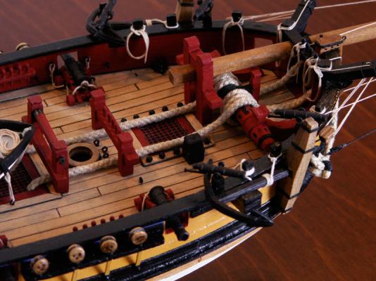
Forward of the boat and main hatch, and just aft of the mast, are the jeer bitts. This structure was not included in the kit, being an addition of my own, but it is certainly a feature of cutters of the period, as is evidenced by models and pictures. It consists of two uprights, with a geared roller at the top and a crossbar beneath and, as its name suggests, it is used for hoisting purposes. The gearing on either end of the top roller, is actually just pencilled lines drawn on the black-painted ends, but it looks effective enough. There is a winding handle on each end, made from pieces of bent wire.
I originally fitted six eyebolts to the deck, to take the various tackles connected to the running rigging that will be belayed to cleats fitted around the base of the mast. I am now not certain I will use all of them, and actually since then I have fitted another two outboard of the anchor cable, one on each side, as giving a better lead. However, one never knows.
Abreast the mast on either bulwark, are two pinrails, with six pins in each. These were supplied with the kit and at the time of fitting them, the number of pins seemed barely adequate. In fact, with rather more rigging seemingly to be belayed, I think they may be woefully inadequate. I should perhaps made have my own rail, with extra pins – but I tell myself, I can always resort to shroud cleats if necessary!
Forward of the mast is a rail. This again was supplied with the kit, but I added six belaying pins to the crossbar, as I intend to belay the the square sail sheets here. Ahead of that is the foredeck grating, down to the crews quarters, with the shot garlands on either side. Offset to the starboard side I fitted a chimney, painted black, and which I imagine connects to the stove below!
Next we come to the bowsprit support, from the kit. This was straightforward, but I felt that it needed pinning as well as gluing to the deck. The heel of the dowel-rod bowsprit was squared, to pass through the support, and I drilled two extra holes through it, to give the impression that the bowsprit can be moved in and out.
I wasn’t too happy with the anchor windlass as supplied, as I felt it didn’t look at all realistic, the completely straight windlass bar being rather strangely made up from short sections! I redesigned it to my own liking, giving it a proper shape, with hexagonal faces. The central section, was made to look as if it had toothed gearing, that engaged with the small bar-mounted rachet, but this again was merely pencilled on the black finish. The equidistant holes for the bars were also just painted black, on the red structure. I had thought about providing the bars themselves, but then the lack of a place to stow them arose – so I stored them below!
The anchors also needed some attention. The anchors themselves I thought were well cast and with the minimum of flash, but the wooden stocks – made as in actual practice from two halves - needed some considerable modification. To begin with they were too long, so I reduced the length at each end so that they were approximately the same length as the metal shank – which fitted with the proportions for an anchor of this type. They then needed sanding somewhat. The modified arms were then glued together around the shank, below the ring, at a ninety degree angle to the arms. Four ’iron’ bands, made from black paper, were then glued around the stocks at appropriate points. Finally, the anchor rings were ’puddened’, or wound round with black cord, which on the real vessel helps to prevent chafe. The anchors are held in their stowed position, by to two supports on the outside of the bulwarks – my own invention – although I think I may have made them a little overlarge. They are also made fast with a length of line, belayed to the two aftermost timber heads. The anchor cables are lengths of plaited cord, that I thought looked somewhat realistic. They are perhaps a little overscale, but I think they do the job. Running aft past the mast, their inboard ends disappear down the fore end of the main hatch, in which I made two squared holes. Their other ends are ’clinched’ to the anchor ring, their circumference making them too large, of course, to tie a knot!
The catheads needed little modification, and are basically as supplied. I didn’t give them any decoration, merely a couple of paper ’iron’ bands, before painting them black. Due to the lack of suitable belaying places I decided to fit a crossbar between the catheads, over the bowsprit, with some pins. Two of these are already taken up, by the inhaul and outhaul lines for the traveller ring, for the staysail. Finally, there is a band around the top of the stem piece, with a ringbolt on the fore side to take the preventer stay when rigged.
Next time: the outboard details, the bowsprit and the mast.
-
Nils,
A very sad story, but you have made a beautiful model of his ship, and indeed of the Pamir.
Interestingly, when the late Donald McNarry built his first miniature of the Herzogin Cecilie he complained of the monotony of having to build three identical masts with three sets of identical rigging!
Michael,
There's always a downside, isn't there?

I'm sure you know of the Pommern, in Mariehamn in the Åland Islands, now a museum to the last days of sail. She is very impressive, and still largely in her original state. A few years ago they made some new sails for her, and she has been under sail on occasion – but also under tow, I think! Ashore near her, is a very interesting maritime museum, full of items salvaged from the vessels of Erikson's fleet, along with documents, photographs, paintings, etc.
I'm sure you'd also be interested in the preserved Viking in Gothenburg.
- Torrens and Mirabell61
-
 2
2
-
Shawn,
Firstly, a welcome to MSW from me. Congratulations too, on the hull and masting of your Albatros, they look really great.

Your spars too look fine, although to me the gaffs look a little short, but what needs some attention is your rigging. You've obviously sussed out that the brown is the running rigging and the black the standing, but it's a bit confusing to work out what is what with the former, since you already have it cut off, I presume to length, and attached.
It would probably have been easier to do it the usual way and work on the standing rigging first, starting with the mast shrouds, and then the stays. I don't know why you have what I presume is the shrouds, half way up the masts, when these should really go round the lower mast heads, resting on the crosstrees, and be in pairs on each side, with the lower end fastened to the upper deadeyes, just above the ship's sides.
After you have completed the standing rigging, you can begin on the running rigging although I've a feeling here that you may have to remove some of the attached lines, and start over. However, I'm sure you can re-use some of it. Btw, a good idea when attaching yards to masts, is to put a small metal pin in the mast at the position you want the yard to be. A corresponding hole drilled a little way into the yard from the rear, not all the way through, will secure the yard to the mast with a touch of metal/wood glue. This will hold the yard while you carefully rig it.
Frankie has given you a few books to pursue and I suggest you read them, in fact all you can, to understand the methods of rigging. There are many different viewpoints on sails, and these will probably be covered in many books.
One thing however, is not to rush your build. Take your time, and you will end up with a far better model. Good luck, and do keep asking qustions here on MSW. I'm sure you will have many expert replies.
-
-
Scratchy,
I think Michael knows the original Pamir was steel, as most were at that period; I believe he means a wooden kit of either her, or another four masted barque.
Michael,
I agree with you, and it would be nice to see a good quality model of this period. However the kit manufacturers have somehow avoided this type of ship, in favour of popular earlier vessels – with guns! I think the only answer is to scratch build. Since you're in that neck of the woods, how about checking out Harold Underhill's sailing ship plans from Brown Son and Ferguson, in Glasgow. I think he may have produced drawings for the Pamir, I'm not certain, but he produced many other plans of well-known vessels from that era.
-
B.E,
Thanks again. Coming from you that's a certainly compliment.
I'll be mentioning the boat a little later.
-
John,
Thanks, glad you like her.
Floyd,
That's kind of my thinking as well, and I am feeling a lot better.
-
Hi Floyd,
Thanks for the kind words. As we both know she's been going (slowly) for a few years now, and I posted a few pics of her on the old DDM site – where I seem to remember posting about your battle station hammocks. However, this is the first time I've attempted to write a proper log, although it is in retrospect, and should keep me going for a while. Actually, now I'm doing it, I'm remembering more than I thought – and recalling some things I wish I hadn't!
We've another couple of months at the cottage, before returning to Stockholm. It's been a good break, at least for my wife. I haven't faired so well, as I've had a painful bout of shingles, which I am just getting over, and which has prevented me from doing many jobs that need doing! I'm just starting to catch up.
The cottage, by the way, is north-east of Stockholm just off the main route to Kapellshar, the ferry port to Mariehamn in the Åland Islands. The nearest small harbour to us is called Spillersboda, which we are just inland from. I'm sure Dr Per can fill you in on the details! I'll try and find a picture.
I trust you had a good summer too, with plenty of sailing – and model building of course!
-
Before I move on to the fittings I should first say a word about the stern, as I found this was one of the most difficult areas to work on. The horizontal planking of the stern piece, both inside and out, was straightforward enough, but I seem to remember that the sloping counter below it presented a few problems.
This was again planked horizontally, and I glued a raised plank around the edge to make something of a feature. This looked quite good, but I remember I had to make two small triangular-shaped pieces of plank to fill in two odd-shaped gaps, on either side at the top of the counter. I can’t now recall exactly why this was necessary, but anyway they were made and duly fitted in place. Although rather dark in the photograph, the one on the starboard side can be made out. As with the upper part of the hull, the counter was left natural.
I wanted to fit a rather more substantial transom rail than that shown on the box lid. This had to bend in two directions, the first following the shape of upper edge, the other the curve fore-and-aft. Because of this ’double bend’, I opted to use a piece of the thin maple planking, and it fitted quite well. The only problem when glued in place was the juncture of the transom rail with the bulwarks, which produced something of an odd angle with the bulwark. I eventually decided that the simplest solution to hide what would have been an unsightly join, was to fit a pair of davits over the stern, made from some spare pieces of wood and which I had seen in some pictures of cutters. Four sheave holes were drilled in the outer end for the falls, but I didn’t rig them although cavels were provided inside bulwarks, just below the swivel guns, to belay them. I should mention at this point that the main rail was put on in three pieces of about the same length, on each side. I found that when dry fitting it, the length made it rather unwieldy, and thought that when gluing, to much would be left to chance! My only regret is that I didn't scarf the joint. However, you can't see the join, as one part of a comedy double-act used to say when referring to his oppo – although you can if you look closely!
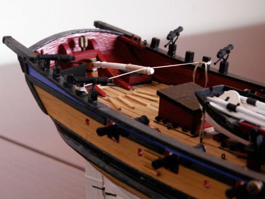
The lower (double) sheet block, for the main sheet, was fixed to a timber fitted between the inner standards supporting the transom, two cleats being fixed to them for belaying purposes. Moving forward, I decided there would have to be some sort of storage for the balls for the swivel guns, and settled on a couple of lockers, one each side of the tiller, the starboard one having its lid open. Since the lockers were oblong and of a reasonable size I divided them in half, the outer compartment housing the ammunition. The other side of the open locker contains the coiled lead line, with the lead on the top. You can just see this in the third photograph. (In my minds eye, the larboard locker also contains the swivel ammunition in the outer compartment, and the log line in the inner.)
Whilst on the subject of the swivels, I decided to reduce their number to two each side at the stern, similar to those at the bow – rather than fitting the three as envisaged in the kit. This was both because I thought three looked rather too many, and I could also imagine the crews getting in each other’s way – especially when trying to get the ammo from my lockers! I discarded the kit swivel supports, in favour of my own make – which are actually made from two eyebolts bent at the top, and glued back to back. The handles are small nails cut off and glued to the underside of the gun.
Like many building this kit I also thought a new tiller was needed, since I too wasn’t happy with the one provided. Made to a scale length of ten feet, as given for the Alert, I laminated it from several layers to get the correct shape, using nails fixed to a board. When dry, it was rounded with sandpaper, and a tenon was formed in the ’outboard’ end, which then fitted into a squared hole in the rudder head. This was a much better, and more accurate, arrangement than the fitting on the kit tiller – which rather strangely, I thought, completely encircled the rudder head. I then glued thin paper strips around the tiller at the rudder end, and on the rudder head itself, to represent strenthening bands. Some tan rigging thread was glued around the business end, to enable the helmsman to ’get a grip’, as it were. (I had originally thought of fashioning a turk’s head knot on the end, for decoration, however I’m afraid both the scale and the tediousness of forming it, defeated me.) To stop the tiller from swinging, I clove-hitched the middle of a line to the tiller, the ends then being belayed to one of the posts on each bulwark, and finished off with rope coils. I glued some ’treads’, for the helmsman’s feet, to the deck in a fan shape that followed the arc of the tiller.
Moving forward, we come to the small structure of the cabin companion. This is not provided in the kit, the space being merely occupied by the aftermost of the small hatches. I found this rather wanting, and thought the young CO deserved a more impressive entrance to his cabin! The companion was made from four pieces of ply from the kit frame surrounds, and given a sloping roof, which has a raised ’hinge’ across it. The after side has two doors each of which, although they don’t open, is provided with a knob!

Next time: more fitting details.
- Dubz, Chasseur, Mirabell61 and 3 others
-
6
-
All the tools under the sun won't necessarily make you a better modelmaker, but buying a few that you really need might just help.
I'd agree with Anthony and Michael, save your money until you really feel as though you need a need a particular tool. That way you'll acquire only those really necessary, and which you'll use all the time, rather than ones you initially thought you needed – but which then get relegated to the back of the shelf or workshop to gather dust.
Oh, yes, Crackers has also given some sound advice – regarding the Admiral!

-
Dirk,
Thanks again.
Brian,
Pleased you like her.
-
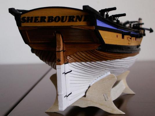
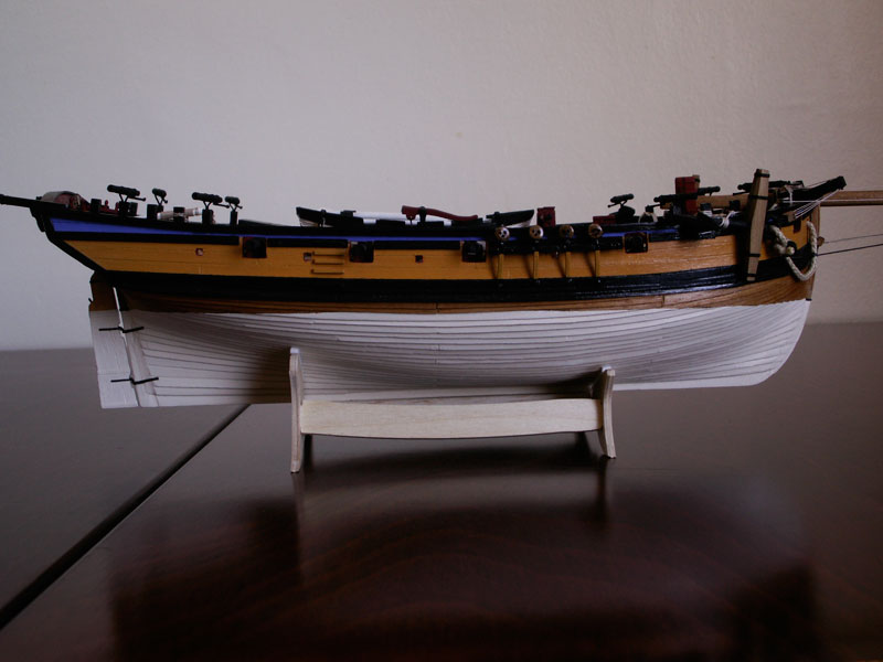
Before I move on, I omitted to mention a couple of items in the previous post. First, I wasn’t particularly happy with the stand provided and thought of various other types, including my own wooden one, a version made from perspex (which can often be very effective), or perhaps employ couple of pedestals (either brass or wood). I deliberated on this for some time before I was more-or-less forced, by progress on the model, to make a decision. In the end, I’m afraid, took the easy way out and decided to go with the stand supplied – although it was somewhat modified!
As can be seen, I cut down the height of the supports to around the bilge area, since this was where maximum support was needed, with rather more being taken from the front supports than the rear. This gave it a much better appearance, removed the somewhat intrusive extensions up the sides of the model, and didn’t affect the stability. A wooden crossbar was then fixed between the supports, angled on the top face to match the that of the keel, and with two small holes drilled through it in appropriate positions. Corresponding holes were drilled in the keel and I found two suitable screws. Then with four thin strips of adhesive padding material added to the arms to protect the model, and following a light varnishing, the stand was screwed to the hull. I decided to leave the colour as it was, being less intrusive – to my mind, the stand should be as ’invisible’ as possible so as not to detract from the model itself. I added the lettering, ’HM cutter ’Sherbourne’ – 1763’ at a later date.
The rudder was planked with three planks on each side, with paper strips around it at suitable points to simulate iron bands. The planks I chose were a little marked, which gave the rudder a old ’worn’ look. I fitted an eyebolt on its after side. Thin strips of black paper simulated the pintle and gudgeon straps. With that well-known concept known as hindsight, I now think the rudder would perhaps have looked better tapered, but there it is.
The last photo also shows the metal lettering of the name, the individual letters being glued on separately. Since I had painted the stern yellow ochre, I thought black lettering would look rather effective. However, to actually position the lettering itself took a little thinking about to get the spacing right. Rather than begin on the left side which would perhaps be usual, but which might very likely end up with too much space to the right, I decided to start with the central letters over the rudder, and work out to each side. Working by eye this method kept things equal, and resulted in the same amount of space on each side of the name. Whilst on the subject, I have not managed to find out how the actual name came about. There is a town named Sherbourne, in the English county of Dorset I used to live in, but I rather suspect the cutter is perhaps named after an Admiralty or Dockyard official. It would be interesting to know.
So, now to the deck. With the gunport strips fitted, the instructions then said something like, ’with a pair of pliers, twist off the heads of the frames above deck level’. What?! I must have read that a few times, to fully understand that’s what they really meant – and I felt that there was no way I was going to do actually that, without causing some serious damage! It appeared to me that it would also leave an unsightly break, which I would then have to spend time tidying up with sandpaper, even a file. Instead, I came up with another solution. Before fitting the gunport strips, I decided to saw about half-way through the frame tops at deck level from the side, with a fine toothed model saw, and to use only the minimum amount of glue in fixing the strips. I reckoned I would then only need to use minimum force to remove the frame tops. It worked well, they came away with very little effort – and I expended very little effort in tidying up the remains. I seem to remember that I planked the bulwarks both inside and out, using scale length planks, as I progressed, in order to strengthen the gunport strips. These were quite weak at this point with little support, merely being glued to the upper edge of the wale. I actually used the thin strips of, I think maple, to plank the inner bulwarks (although I think they were supposed to be used for the deck) since they fitted round the bow more easily, and were painted red.
I decided to more or less follow the colour scheme of the Alert on the cover of the AOTS book, for the outer bulwark planking. I opted to use yellow ochre for the planking, with red in the gun and sweep ports, black for both wales, with a line of blue between the upper wale and the capping rail.
The deck was laid in three-step-butt fashion, working from aft forward and from the centre out, the outer planks being joggled into the margin plank. One side, and one end, of each scale plank were ’caulked’ with black rigging cord. The same cord was also used to caulk around the hatches.

Next time: the various fittings.
-
Hello Gregor,
Only too happy to – and its nice to be a motivator! I'll be mentioning the colour scheme and those stern davits in another post. However, even though my model might be inspirational, I'm sure you'll be wanting to give your own Sherbourne the personal touch.
You're doing a great job on her, I see.
-
Andy,
I appreciate your comment. You're right, not many attempt clinker planking but I think they should, on an appropriate model of course. It might look difficult, but it's really no harder than carvel planking.
-
B.E.
As always, your comments are much appreciated.
Pleased you like the colour scheme – I thought it an improvement on the rather drab one on the box lid! I'll probaby say a little more about it later in the log.
-
Dirk,
Thanks again, although your magnificent Sherbourne puts mine in the shade.
-
I omitted to fit bow and stern blocks when framing, but this was mainly because I didn’t know of them back then (well, that’s my excuse). They may perhaps have helped, but I don’t recall any particular difficulties in planking the bow or stern as a consequence.
I really didn’t encounter that many problems with the first lime planking either and it seemed to go relatively smoothly, provided the individual planks were properly tapered. I had also never thought to cut a rabbet line for the garboard plank, however, thinking about it in retrospect, it would probably have been a good idea. (In passing, I have sometimes wondered why the kit manufacturers never think to pre-cut this, since its placing is somewhat critical, and I would imagine is something of a daunting prospect for the beginner.) A fore rabbet, up the stem, would also certainly have been advantageous since I encountered a problem with what I have termed ’plank creep’. This is where the first planking, and thus by association the second, comes rather nearer the bow than necessary – and is your own fault! It is not that noticeable now, but you can see it should you care to look closely (please don’t!) Anyway, I tried to ensure a close fit of the garboard plank, by sanding down the inner edge, and this seemed to make a good joint.
Next came the second walnut planking, and here I made a perhaps ’radical’ departure from the instructions (easy enough to do now, but in those distant days…) and clinker-plank the second layer. All that I had read about cutters told me that their hulls were so planked, and inherited from vessels of an earlier period, so I wondered why the Sherbourne was of carvel construction. However, having been designed by Thomas Slade (responsible for the design of the Victory two years later) and built in Woolwich Dockyard, the answer appeared obvious – they were more used to that kind with warship construction. I believe Chris Watton, the kit’s designer, has also said she was carvel. I imagine that the real Sherbourne would probably have been clinker planked, as was more usual, had she been constructed in a private yard. Moreover Peter Goodwin, in what had now become my ’bible’ (the Naval Cutter Alert), maintains that clinker construction remained in cutters until around 1810 – apart that is, from those constructed in the Dockyards. So, I persuaded myself I was on sort-of-safe ground for the project, and in any case I wanted to try the technique – so, clinker it was to be!
Planking of course had to commence at the garboard strake, since the planks above overlap onto those below. I overlaid my planks by about a third, which seemed about right, sanding down the top edge of each plank so that it formed a good joint with the one above. A thin bead of glue along the top of the strake below, plus a small amount along the reverse of each plank, ensured a good bond. I learnt early on not to use too much glue, as it tended to seep out onto the planking, which of course was not desirable! Provided the planks were sufficiently tapered at bow and stern, I don’t think I encountered many problems – or perhaps I have conveniently forgotten about them! A few small stealers were needed at the stern, but apart from that the planking went surprisingly well.
For both planking layers I opted to use scale length planks, staggering them as in full size practice. This was not only more historically correct, but I found that the shorter lengths made for easier positioning. I believe I planked about three strakes, on alternate sides, until the planking was done, and it was actually quite exciting to see it progress. At the time I was a member on the old Dry Dock Models site, and remember that posting a few pictures of my build encouraged at least one other member there to try clinker planking for himself. His results were pretty impressive too, so far as I remember.
Perhaps I should say a little about painting the waterline. Marking this was quite literally achieved by cutting a hull-shaped hole in a piece of hardboard, gradually enlarging it until I was satisfied the model was at the height I required, and then drawing a line with a pencil around the hull. Rather heath-robinson, but it seemed to work! The painting was a little tricky, especially at bow and stern, where the lie of the planks tended to interfere with a good line, but I think I managed it reasonably well. I opted to use an ivory shade rather than white, since it is a largish area and I felt that the white would be too harsh. It also has a somewhat old look to it. The planks from the waterline to the wale were left natural, although they were treated with beeswax.
The hull pictures are reproduced below:

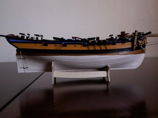

Next, the bulwarks, stern and deck.
- paulsutcliffe, garyshipwright, Dubz and 4 others
-
7
-
David,
Thank you.
Yes, cutters and smaller vessels make good models don't they? Glad you liked the photos; there'll be a few more in the next update.


Sherbourne by Stockholm tar - Caldercraft - 1/64
in - Kit build logs for subjects built from 1751 - 1800
Posted · Edited by Stockholm tar
Some details on outboard side of the bulwarks are worth a mention. The Sherbourne has four sweep ports per side, and I had thought to make the sweeps themselves and stow them on deck. I went so far as to make up the four on one side, of roughly the correct length and circumference but minus the blades, the intention being to fit them on one side of the main hatch. The other four, of course, would go on the other side. However, I couldn’t make them fit satisfactorily with the other fittings already in place, so I then thought of putting them in racks on the bulwarks. However, as that idea didn’t seem to work very well either, I decided not to fit them. Quite how they stowed them on the original cutters, much less how they manouvered and operated them, I have no idea – my guess is with some difficulty! (As Sherbourne spent her approximately twenty-year working life in the English Channel, I’m not sure she would have used them much at all, since that stretch of water is rarely calm and without any wind. I therefore felt justified in leaving them off!)
Another feature I considered were the gunport lids which, perhaps strangely, are not provided for in the kit. In the end I didn’t include them, but I suppose the option is always there to make them should I wish to, particularly for the ports in the bows where I imagine it might get rather wet!
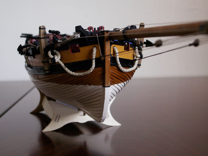
Whilst at the bows, I have already mentioned the main and upper wales. Butted up to either side of the stem I fitted small, shaped, verticle pieces of black painted card, effectively joining the two black wales, and which I thought turned out to be a nice feature. Two black-painted timbers do the same job at the stern. The channels and their support ’chains’ are both glued and pinned to the bulwarks, due to the stresses likely to come from the shrouds. I painted the channels black, but left the lower deadeyes natural, after much debate as to whether to paint them as well. The chains are yellow ochre to match, and blend in with, the hull - their lower ends being painted black at the level of the lower wale.
We now come to the bowsprit. This was more-or-less as straight from the box, apart from being cut to length and being squared at the heel. I didn’t give it much of a taper, since these were fairly hefty spars and were required to take quite a lot of strain at their extremity. Here were fastened the cranse iron around the spar, which I made from black paper and to which the bowsprit shrouds were fixed by lugs, and the triple block to take the topgallant forestay and the topsail braces. I used ringbolts with the ends cut off for the lugs, fastened equidistant around the spar. Just inboard of it there is a also sheave hole for the jib traveller ring outhaul, thus it can be appreciated that the bowsprit would have to be pretty substantial.
The spar fits into a half round cut-out in the port side rail next the stempost, and it was a matter of patiently (!) sanding the aperture and then trying the bowsprit until I was satisfied it sat properly, with its heel resting in the foredeck support. Just before fitting, the bowsprit was stained and its end was painted black, the whole spar then being beeswaxed. After gluing it in place an ’iron’ band, made from a strip of black paper, was then fastened over the spar, to represent the iron retaining fitting.
The bowsprit shrouds, one each side, consist of two parts. The black standing part has one end made fast to an eyebolt in the main wale at the bow. The other is joined to one of a pair of double blocks, its corresponding block being connected to one of the lugs on the side of the cranse iron. A running rigging line reeves between the two, coming off of the block at the end of the spar and running aft to one of the timber heads each side of the bow, where they are made fast.
At this point I decided to fit the traveller ring for the jib and, having found a suitably sized metal ring, ’puddened’ it and then glued it to the bowsprit. Because the sails wouId be furled, I glued it at a suitable ’run-in’ position. I then fitted the outhaul and inhaul lines, which are made fast to two pins in the rail that I fitted between the catheads. From the ring, the former reeves downwards through the ’sheave’ in the bowsprit, as mentioned above, then back to the bow where it reeves through a single block on the starboard side of the stem at the main wale. It then runs up and over the bulwark, before being made fast to the bow pinrail. I think this arragement makes for a better lead for the outhaul, rather than having it run along under the bowsprit where it could get tangled up with other fittings. I followed the example given for the Alert. (I passing, I have found it a good idea to make a small groove along the spar on each side in way of the rope, since it looks as though the line actually passes over a sheave rather than just going through a hole, and sits closer to the spar.)
There is one other feature, at the aft end of the outboard bulwarks. These are the boarding steps up each side, between the aftermost pair of guns, with corresponding ones on the inside of the bulwarks. Another interesting detail, which no vessel such as this should really be without – after all, how else are the crew to board her from the boat? This was probably a frequent daily occurrence with cutters like Sherbourne, in her line of work.
With the hull and bowsprit finished, it was time to think about the mast. I won’t go into much detail this time except to say that both it, and its topmast, were much modified from that provided with the kit!
Next time: the mast and topmast, and the boom. (Apologies by the way for the recurring use of photographs – but I get the impression you won't mind!)