.jpeg.882f0a147f14858c9e673da7e13d8ebe.jpeg)
RossR
-
Posts
531 -
Joined
-
Last visited
Content Type
Profiles
Forums
Gallery
Events
Everything posted by RossR
-
.thumb.jpeg.ffac2f8a24d212961a83eab4efb06a6c.jpeg)
Buccaneer by Krakord - OcCre - 1:100
RossR replied to Krakord's topic in - Kit build logs for subjects built from 1501 - 1750
I like your weathered / distressed deck. -
Looks great as usual. Do you make the hooks or are they PE or purchased?
-
If you aren’t already following it, you should check out Ronald’s Sphinx build log. It is fantastic.
-
Good luck with this project. Looking forward to following along. you mentioned patience in your post and I feel like I was at a similar point after a couple of builds. Don’t be afraid to redo things if the aren’t quite right. good luck.
- 12 replies
-
- 1
-

-
- cutter
- Sherbourne
- (and 1 more)
-
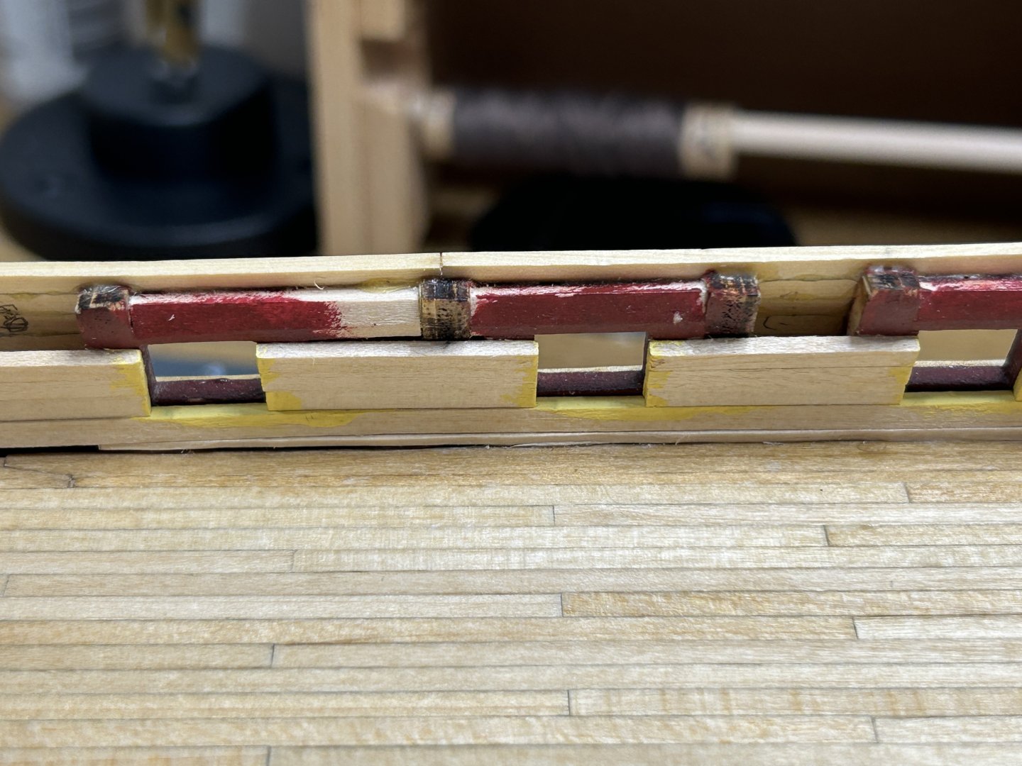
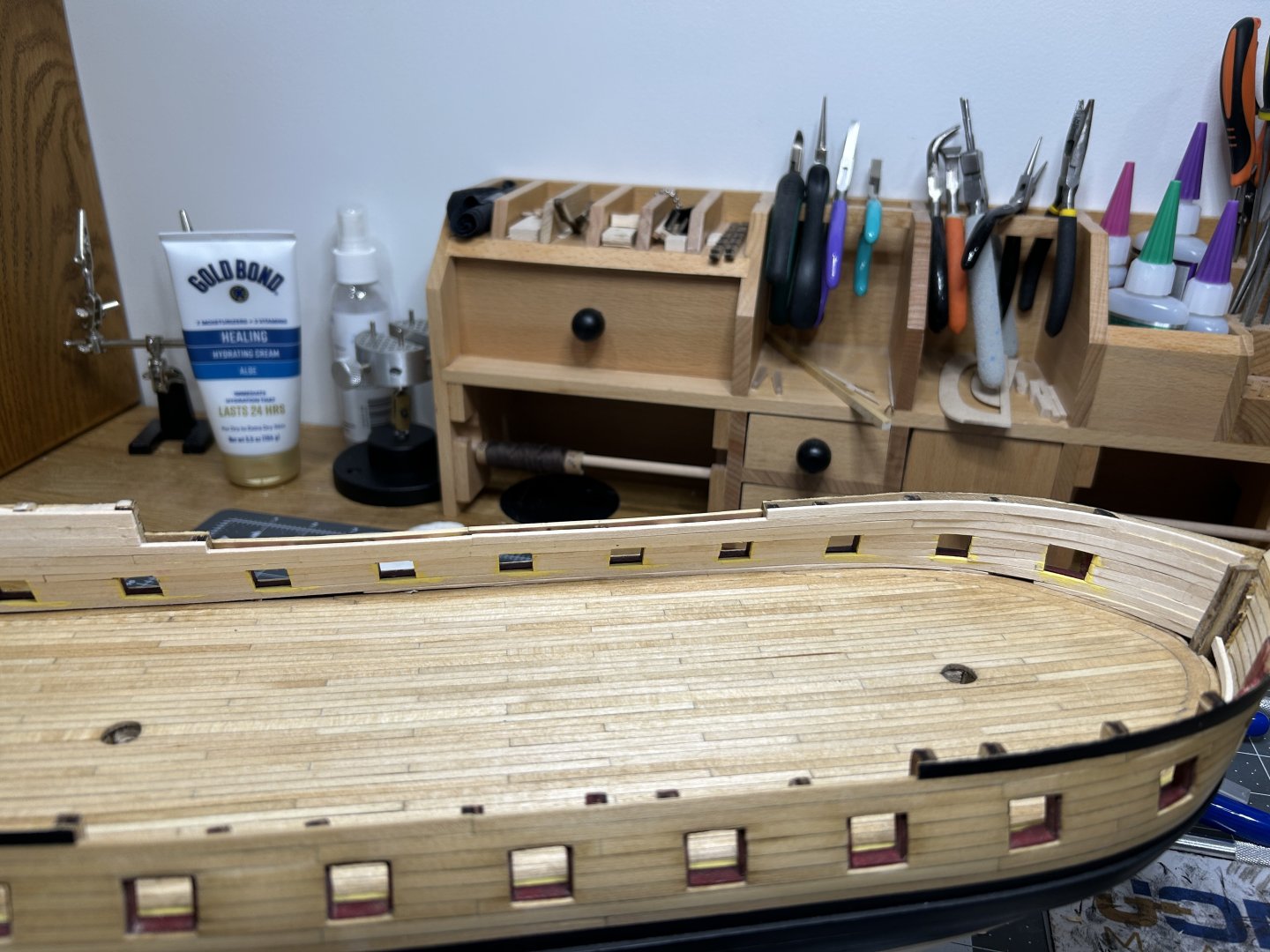
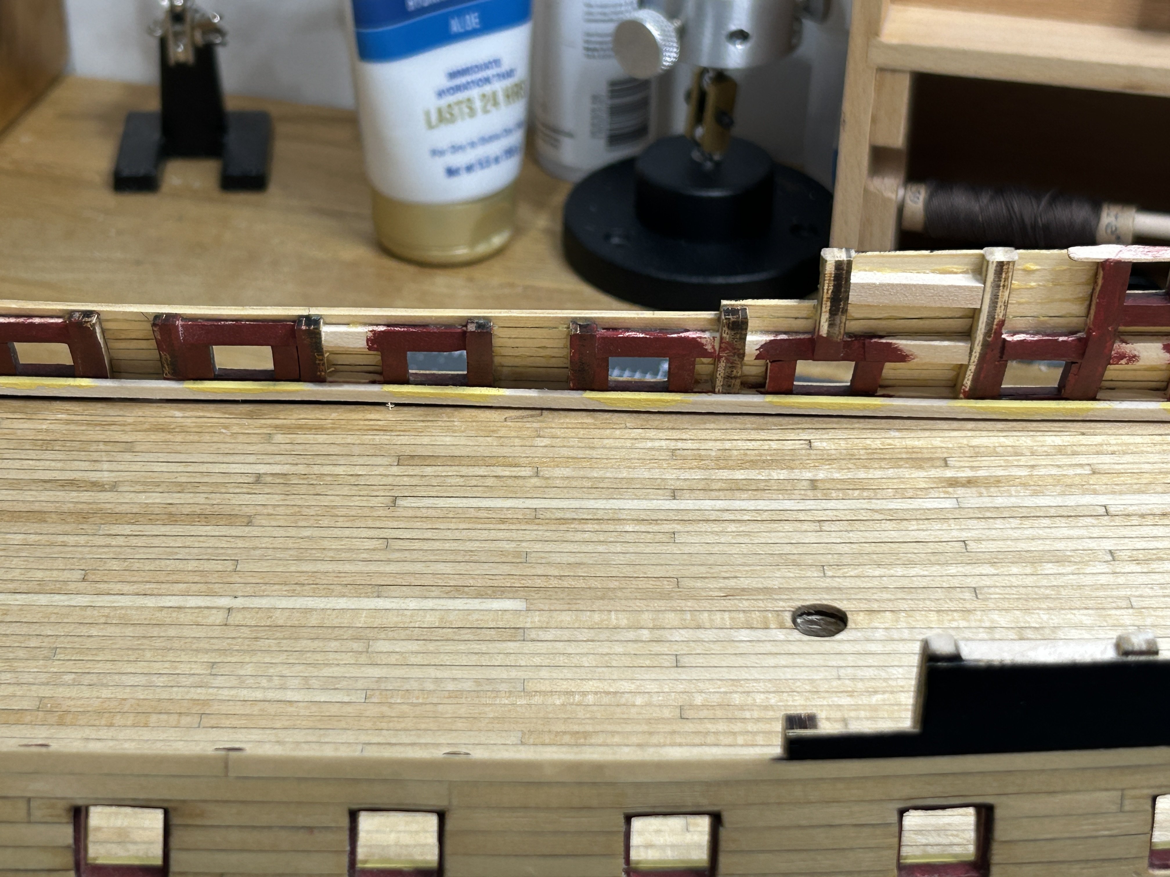
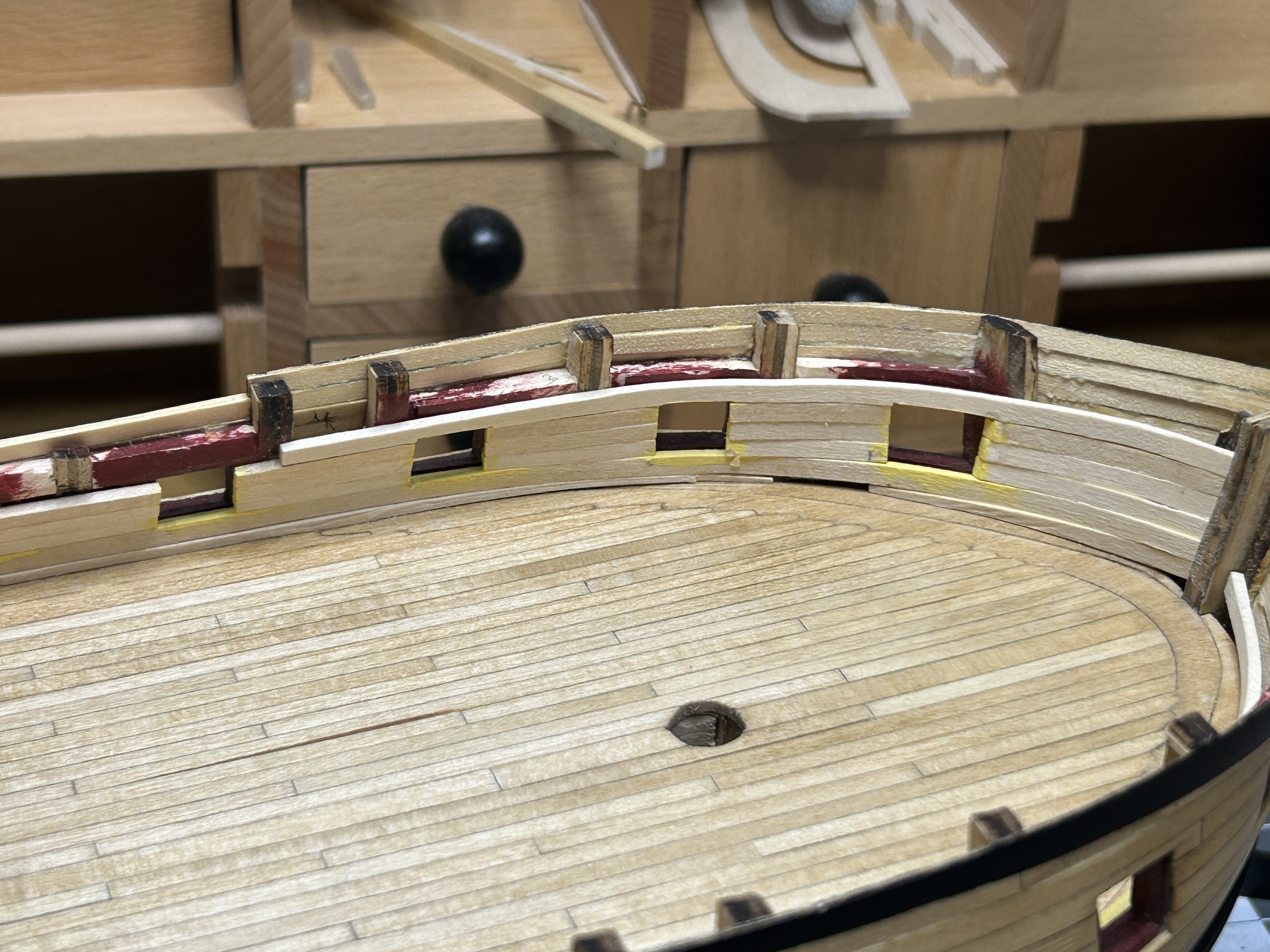
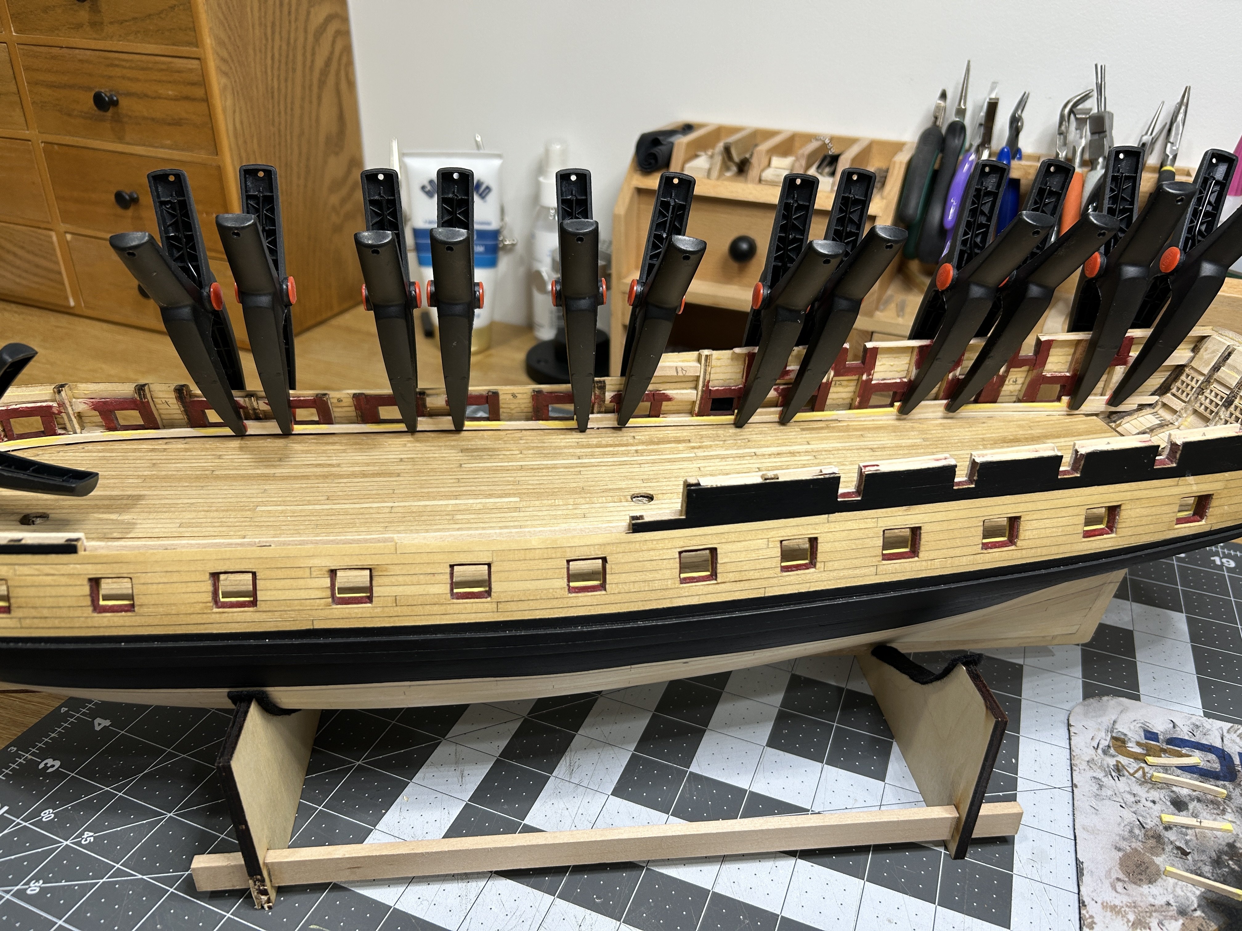
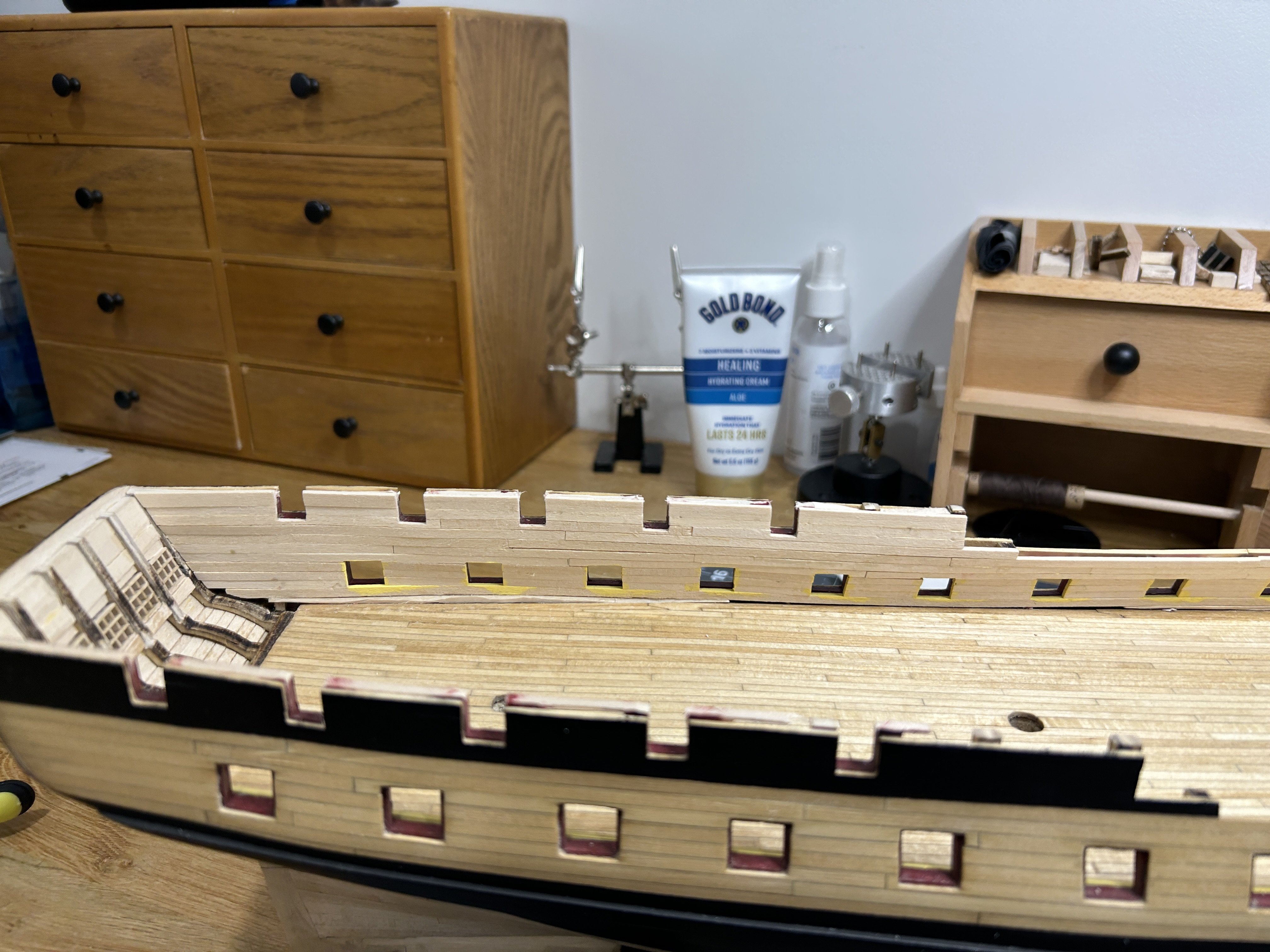
I have been making some progress planking the interior bulwarks. The instructions said to install the first plank as one continuous plank along the entire length of the ship with the top of the plank level with the bottom of the gun ports. The interior of the bulwarks at the gun deck level will be painted a pale yellow. The instructions were not clear whether the edges that are exposed at the gun port should be yellow or red, but some of the photos in the instructions indicated that they were painted yellow on the prototype. I went with painting them yellow and I chose to paint these edges before installing the planks to make it easier. I need to add some filler material in a few spots so that there wouldn't be any gap between the planking and the waterway which will be installed later. The planking around the quarter deck gun ports will be painted red as well as the bulwarks above the upper decks. I didn't paint those edges in advance since everything adjacent to them will be painted the same color. I have one side fully planked, and will be working on the other side and then the stern next. Thanks to everyone for the view and likes.


-
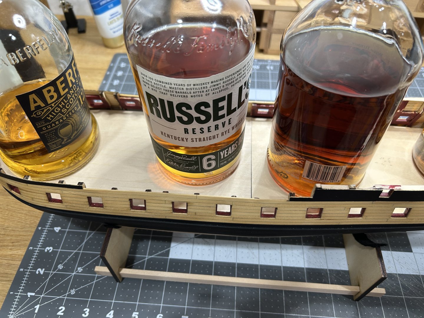
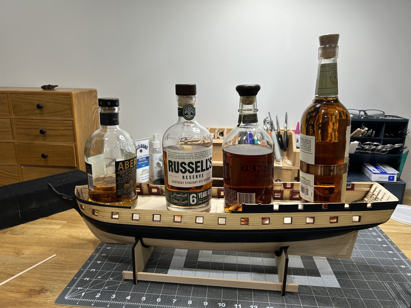
I will often use whisky bottles to weight down glued decks, but I also approve of your method. Looking forward to following your progress on this project.
-
Current Build: USF Essex - Modelshipways Completed Builds: HMS Beagle - Occre Frigate Diana - Occre Santisima Trinidad Cross Section - Occre 18th Century Merchantman Half Hull - NRG On the Shelf: Sultana - Scratch Build US Brig Syren - Model Shipways Albatros - Mantua
-
Glad you are starting up again. Looking forward to following along.
-
Cutters, Choppers, Guillotines, Slicers
RossR replied to MintGum's topic in Modeling tools and Workshop Equipment
With the Ultimation slicer, for material thicker than 1/16, you would want to make your initial cut a little long the trim the final 1/32 to 1/16 off with a second cut. You will get a really nice square cut using this method. I also have the Ultimation sander and will often use that to square up the end. I don’t know if I would use the slicer on material 1/4 inch thick. I am sure it would cut it, but seems like it might be pushing the limit of the tool. When I have stuff that thick I cut with a had saw and clean up the end with the disk sander. -
I am currently building the USF Essex. The bulwarks on the gun deck will be painted yellow and the deck has been stained with honey oak stain. After the bulwarks are planked I will be adding the waterway. should the waterway be painted the color of the bulwarks, or should it be stained like the deck?
-
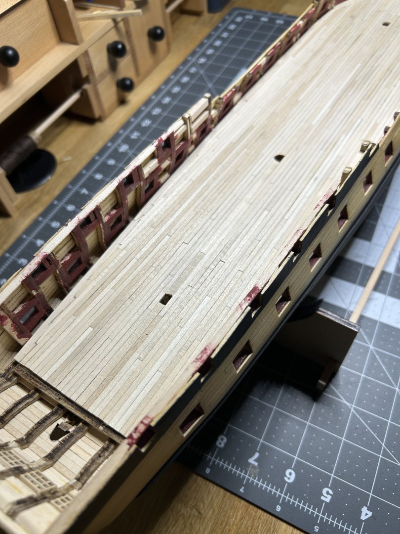
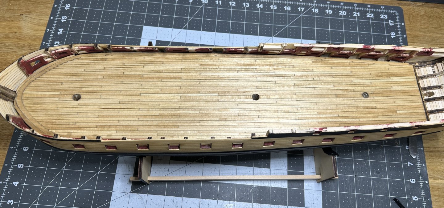
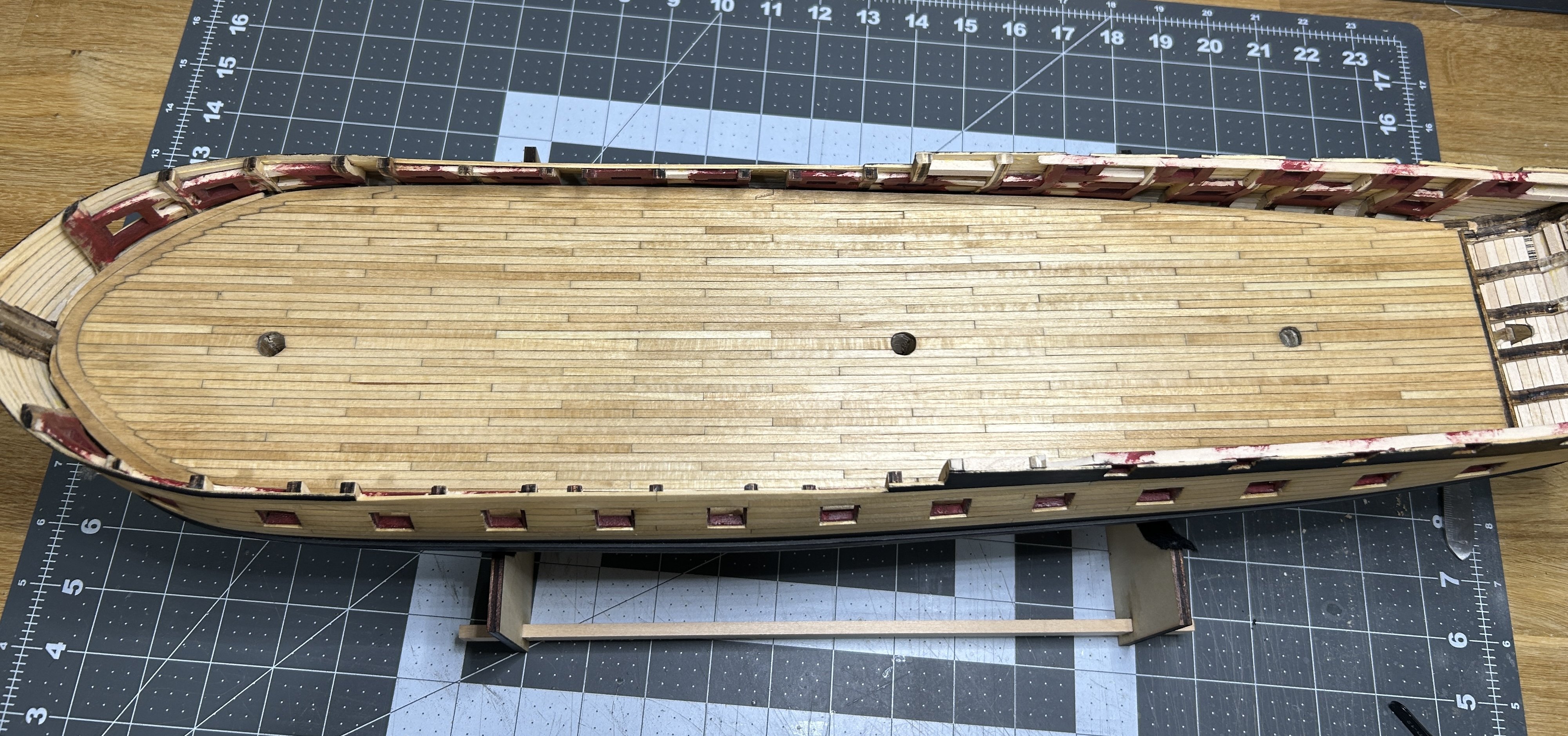
I have finished the rest of the Decking on the gun deck. I sanded it with 80, 120 and 220 grit sandpaper progressively. There were 3 or 4 spots that I had some gaps in my joggling. I used some stainable wood filler on those gaps. I finished the deck with Minwax Pre-Stain, then a coat of Minwax Golden Oak stain. After that two coats of shellac with a sanding with 000 steel wool after each coat. Next up is the planking on the interior of the bulwarks and then the waterway. Work will be really busy for the next 4 - 6 weeks so progress will be slower. Really happy that I have this deck finished before work gets busy.

-
Your painting of the PE parts is fantastic. The columns look incredible.
-
HMS Victory by ECK - OcCre - 1/87
RossR replied to ECK's topic in - Kit build logs for subjects built from 1751 - 1800
Nicely done. -
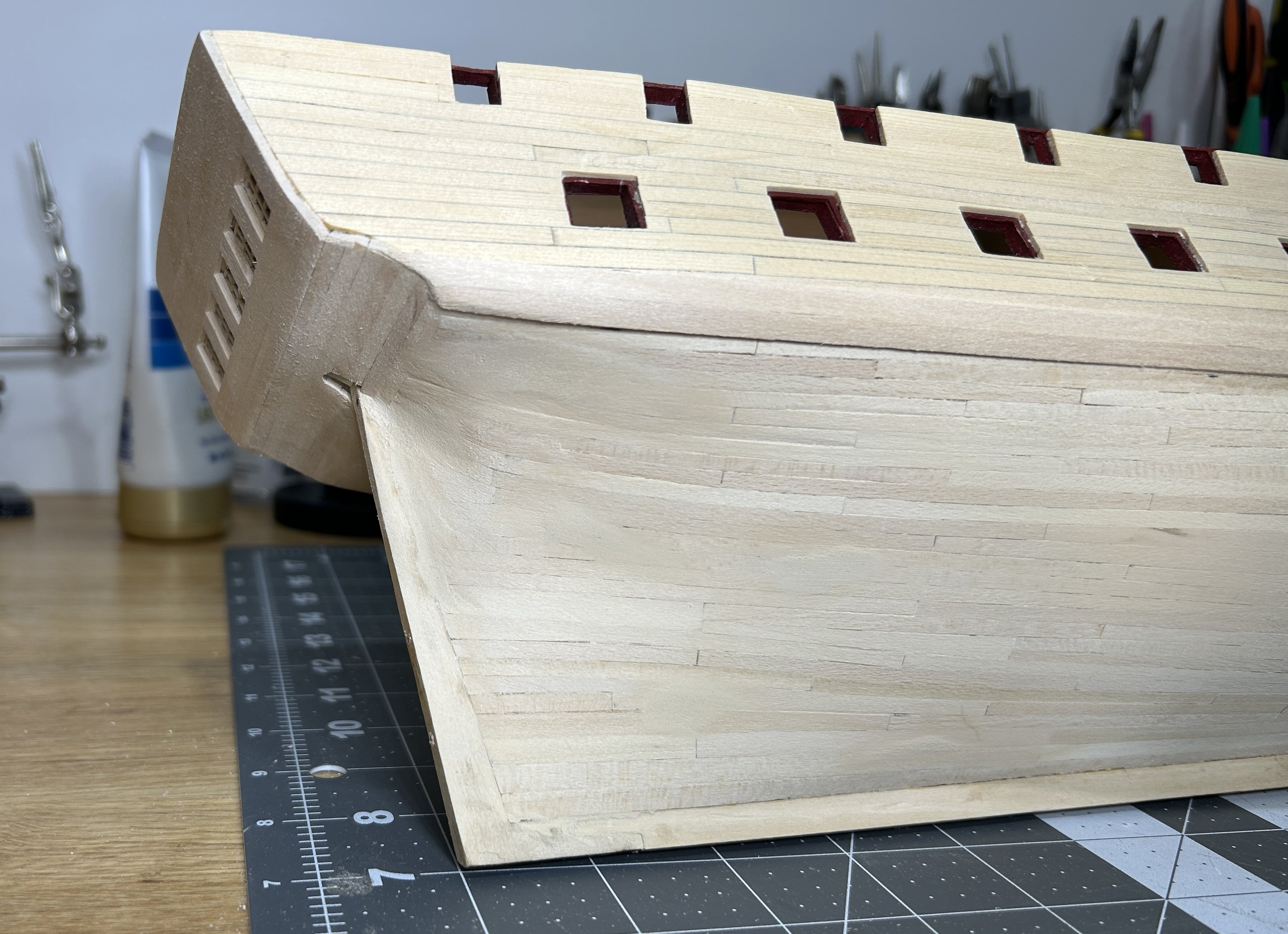
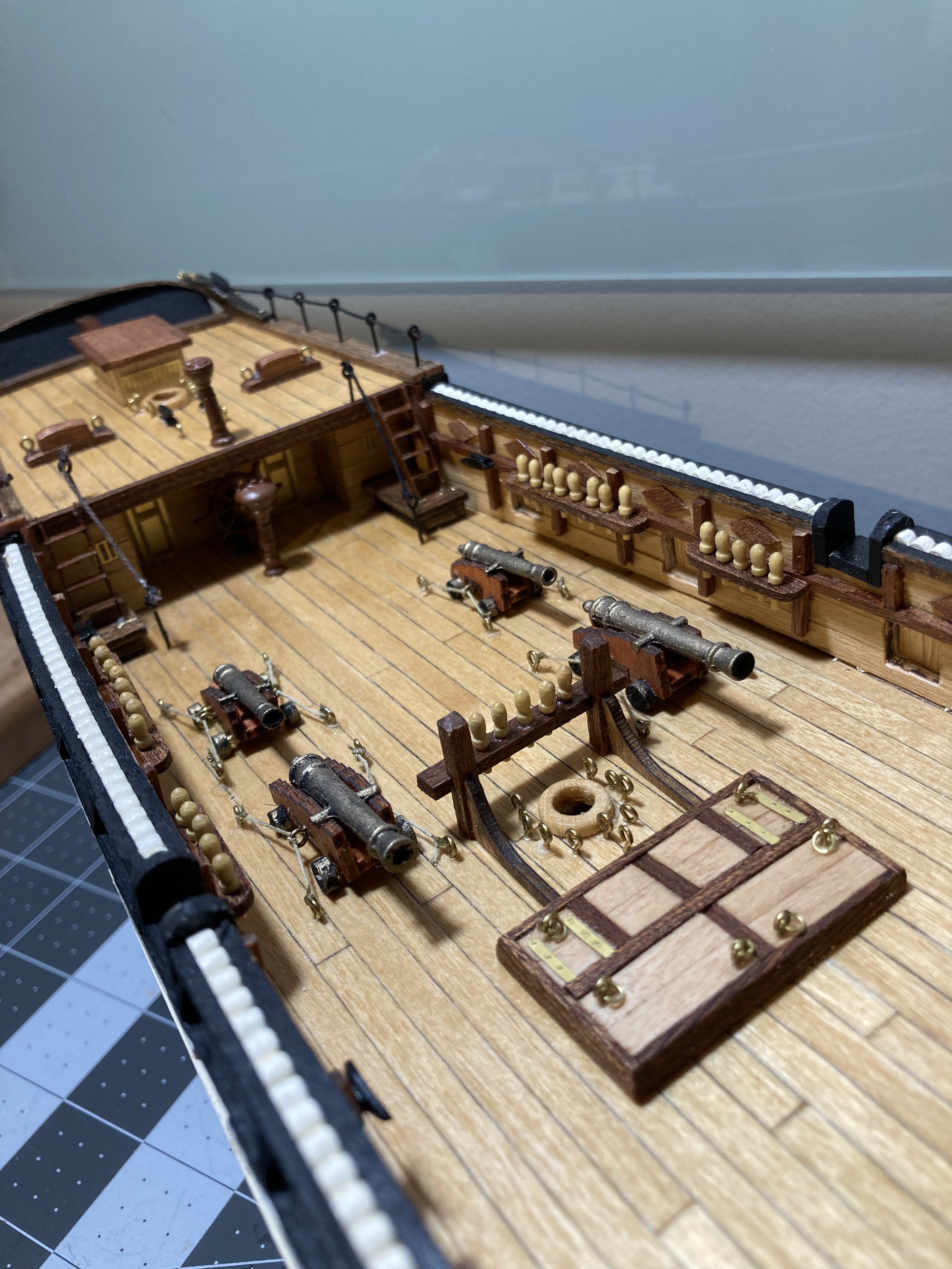
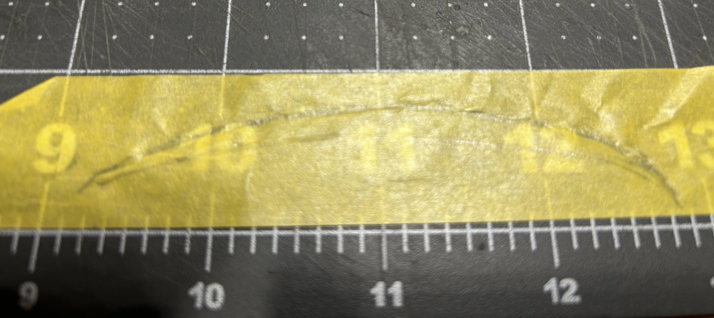
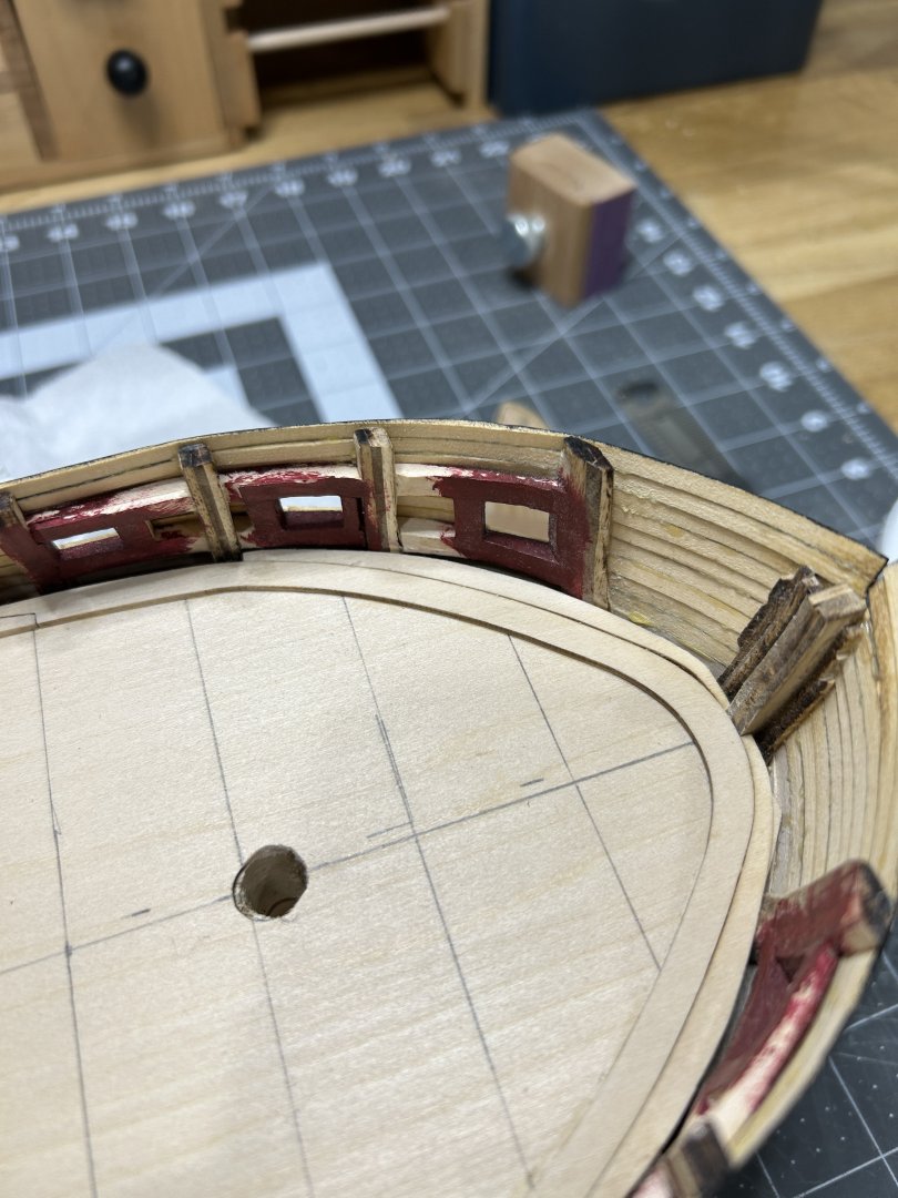
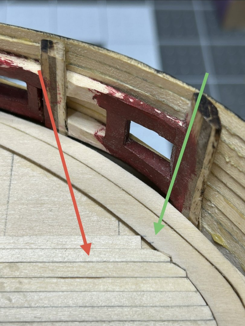
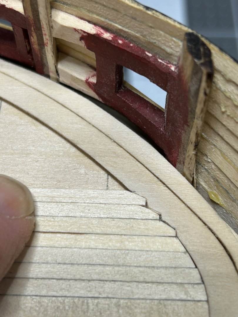
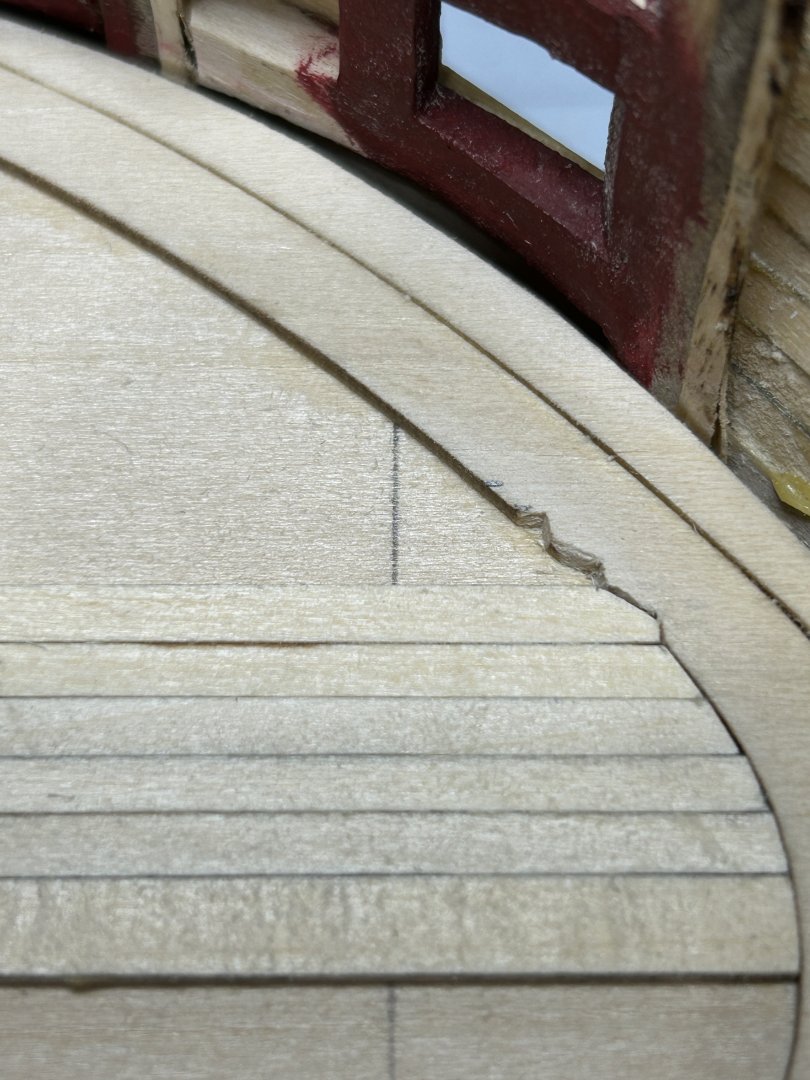
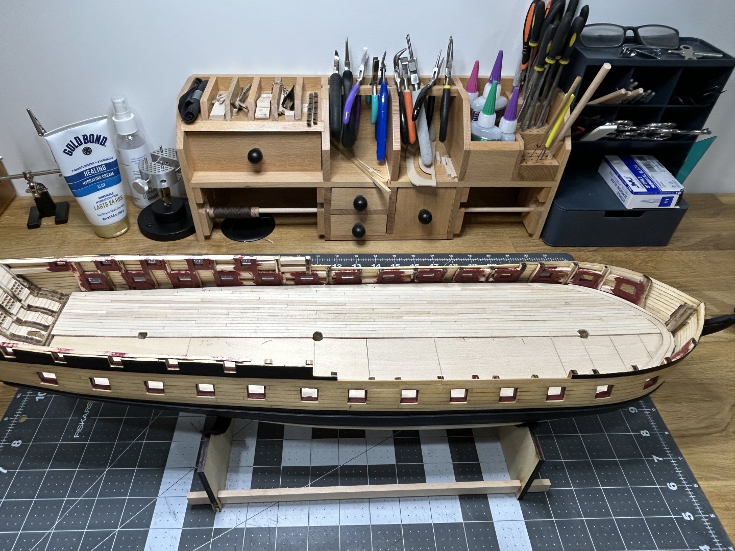
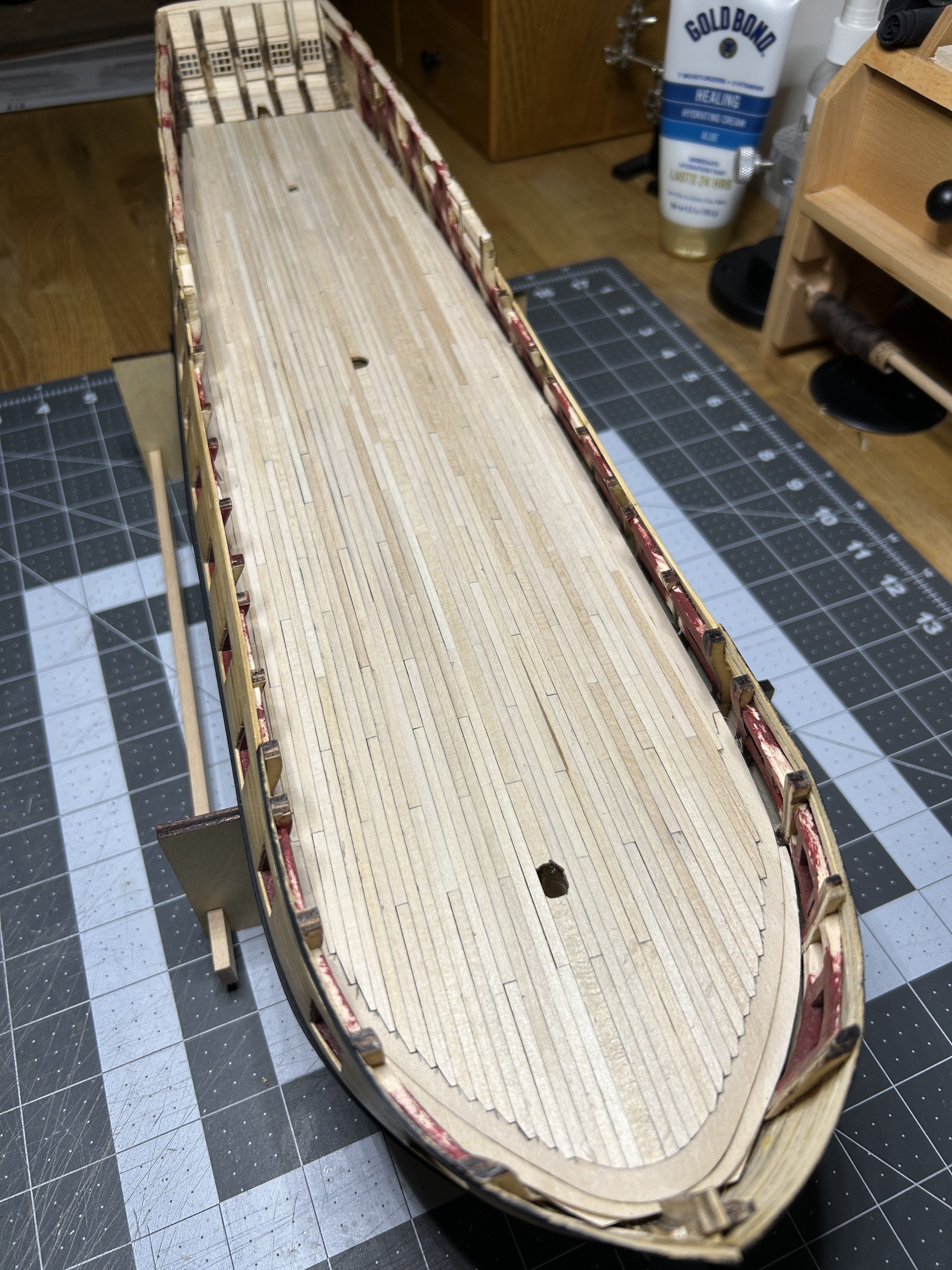
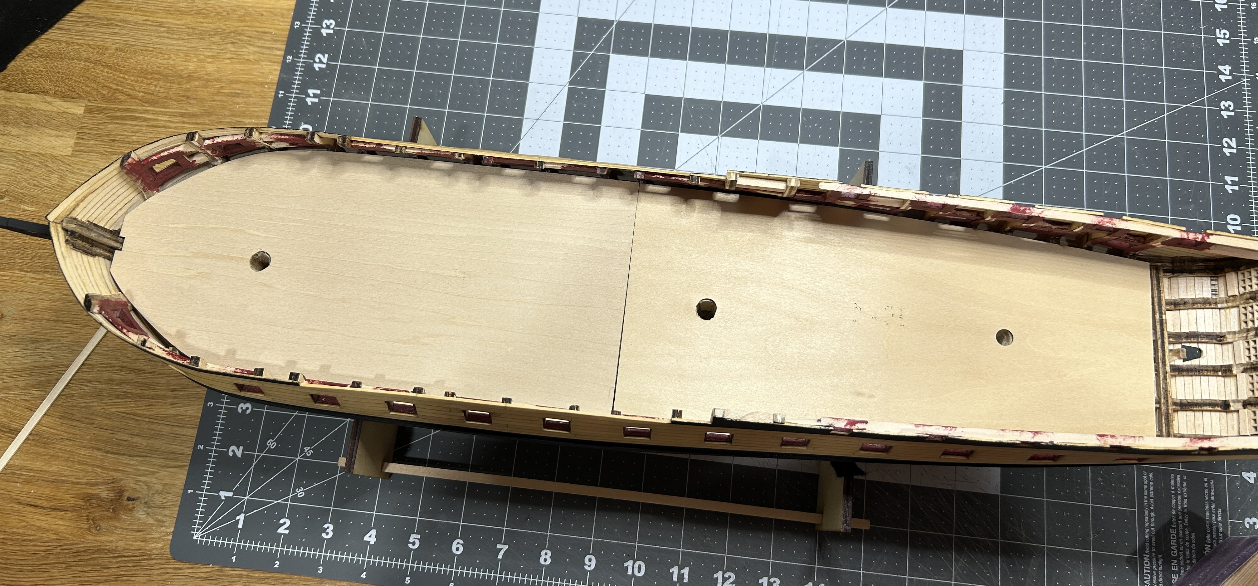
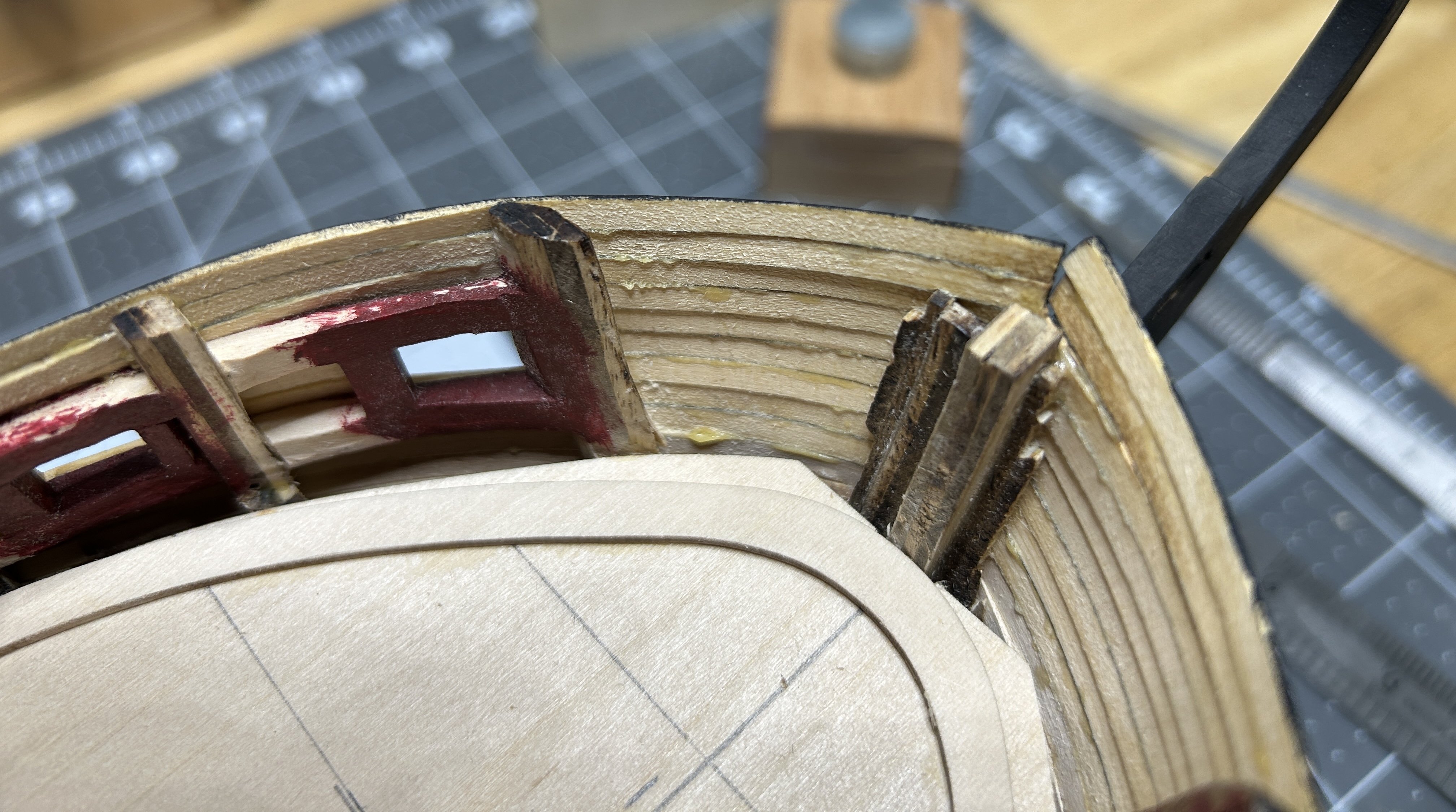
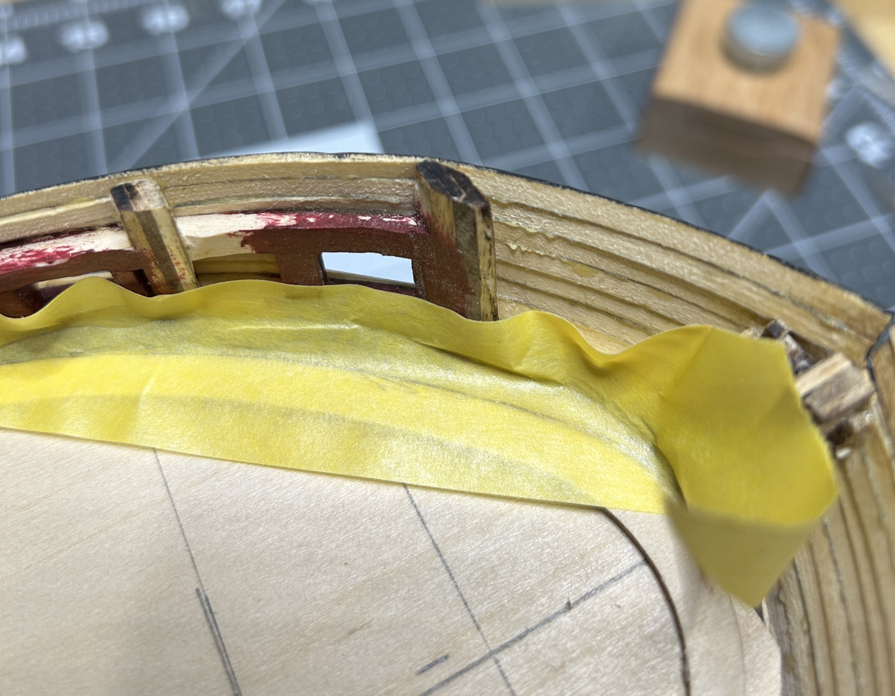
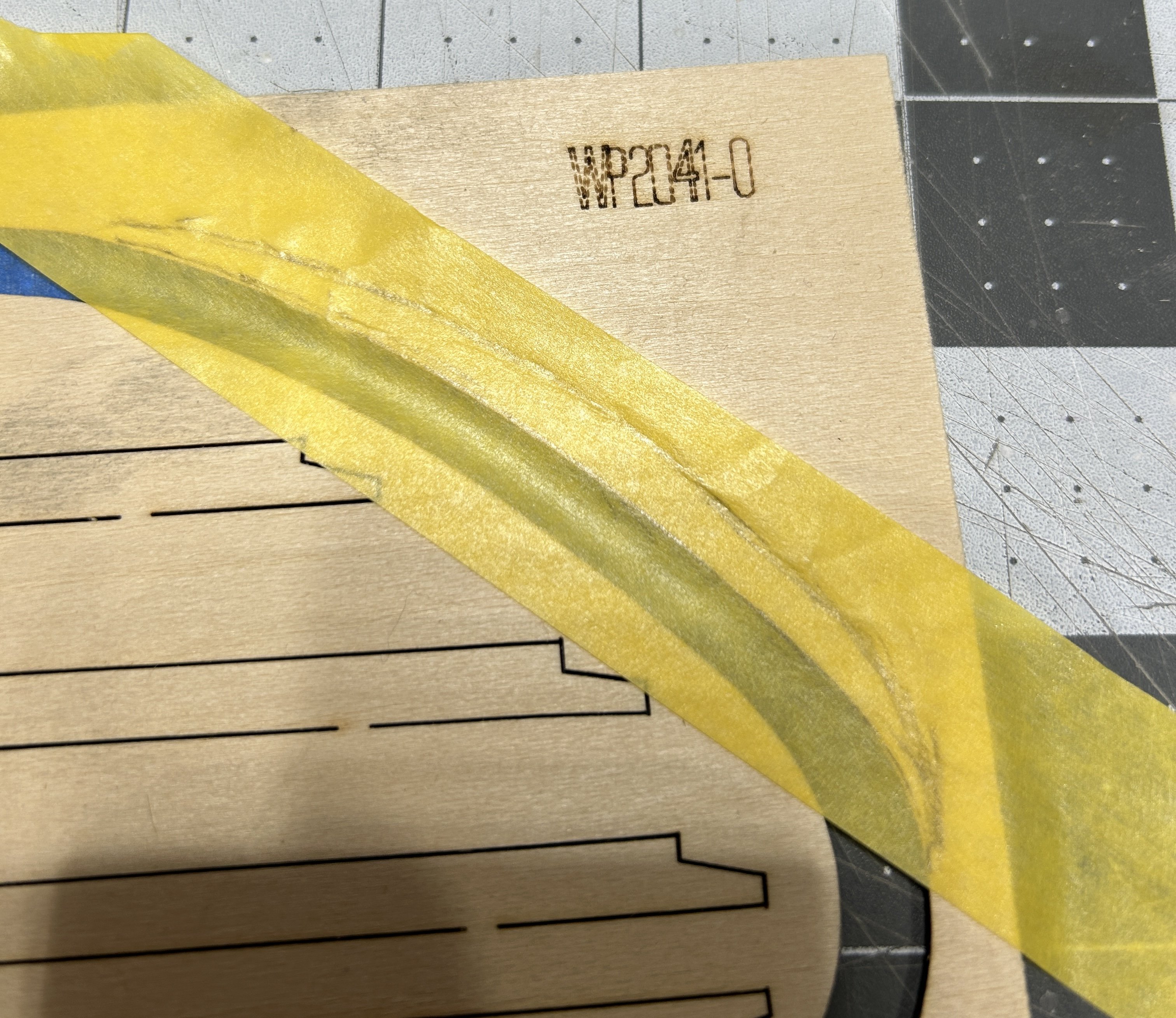
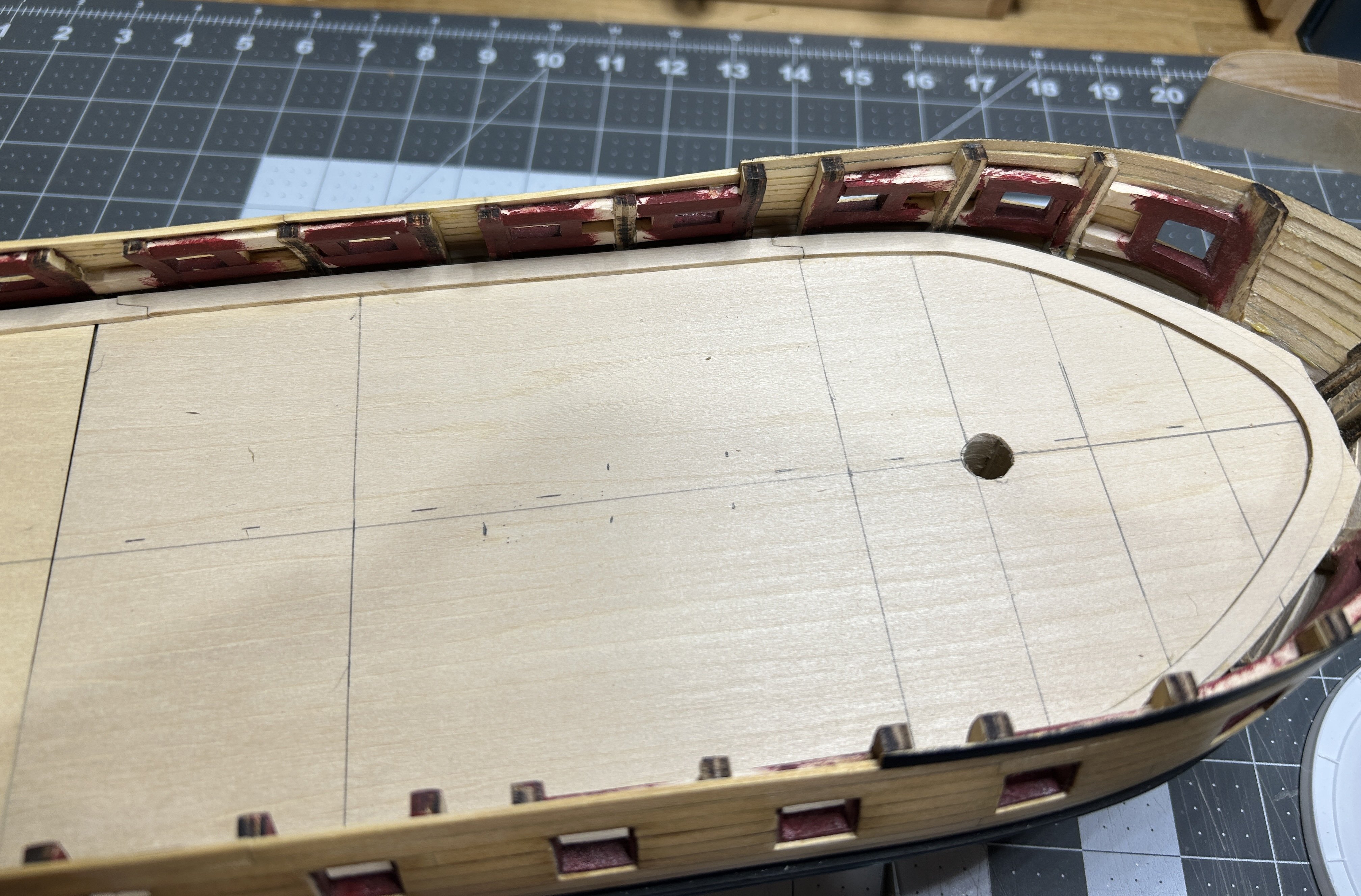
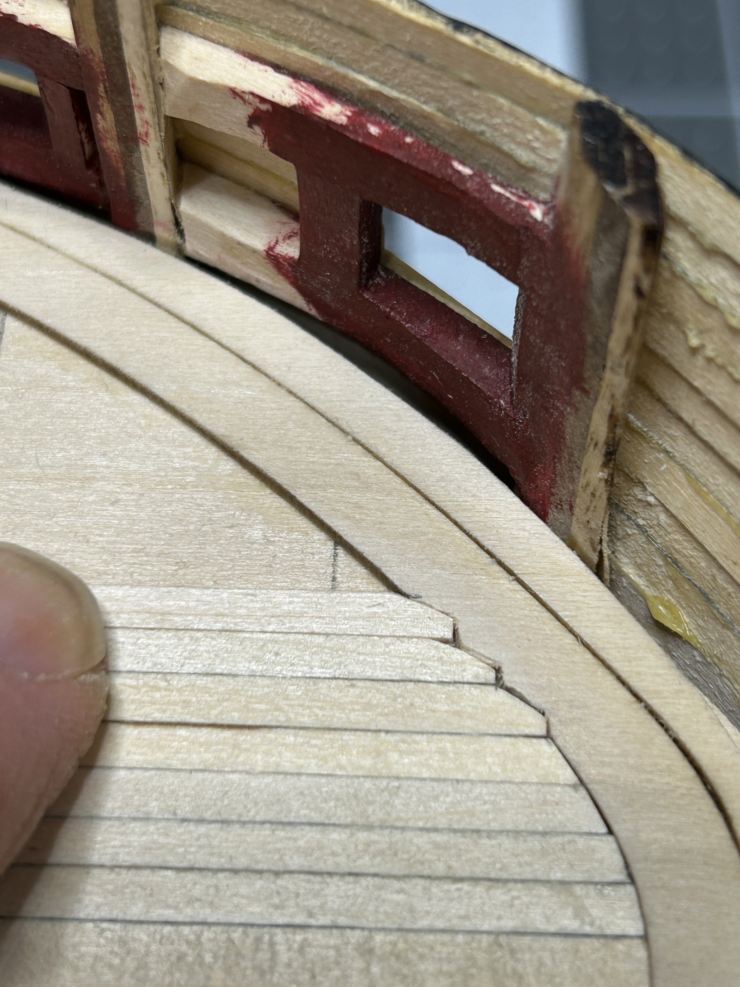
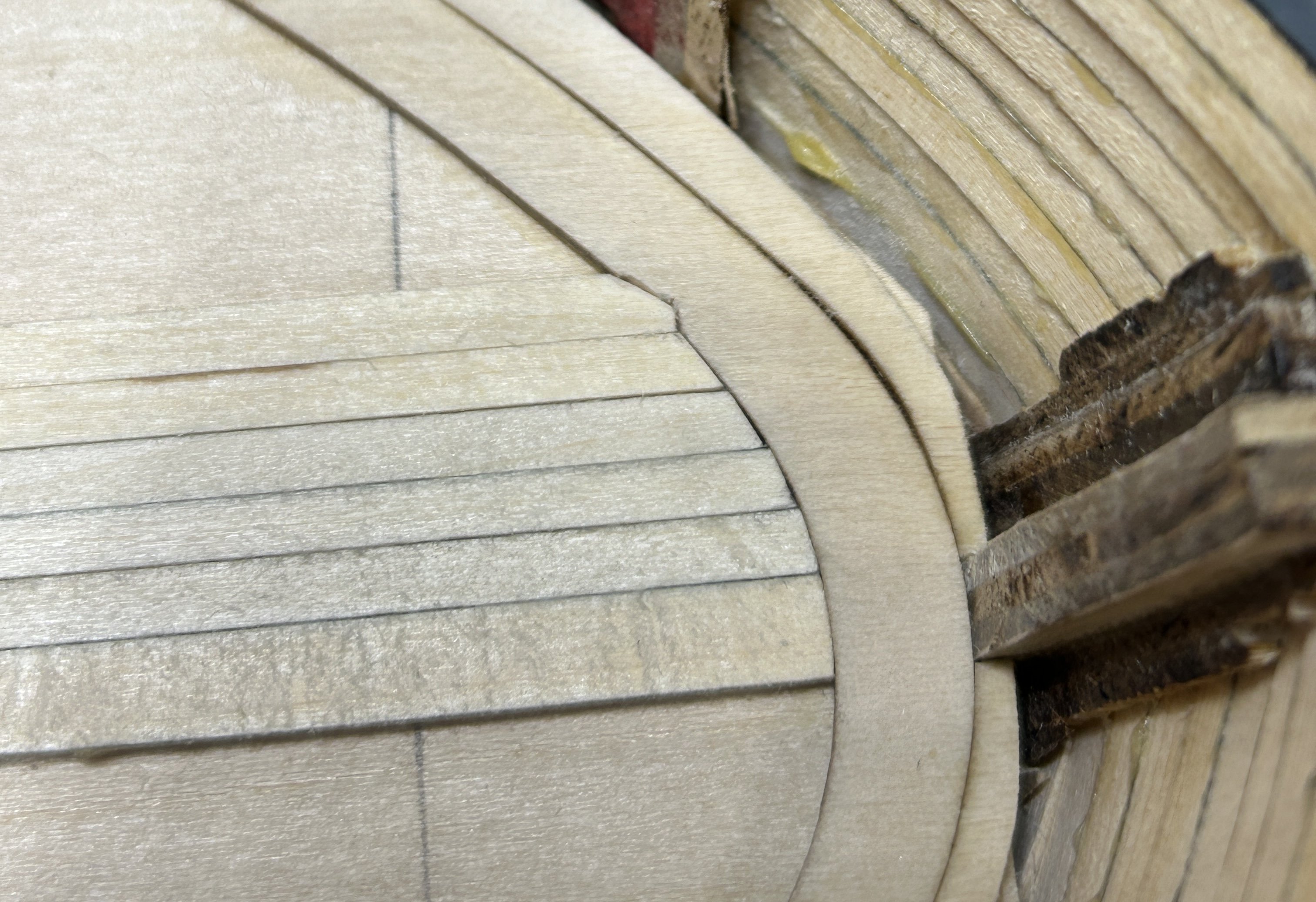
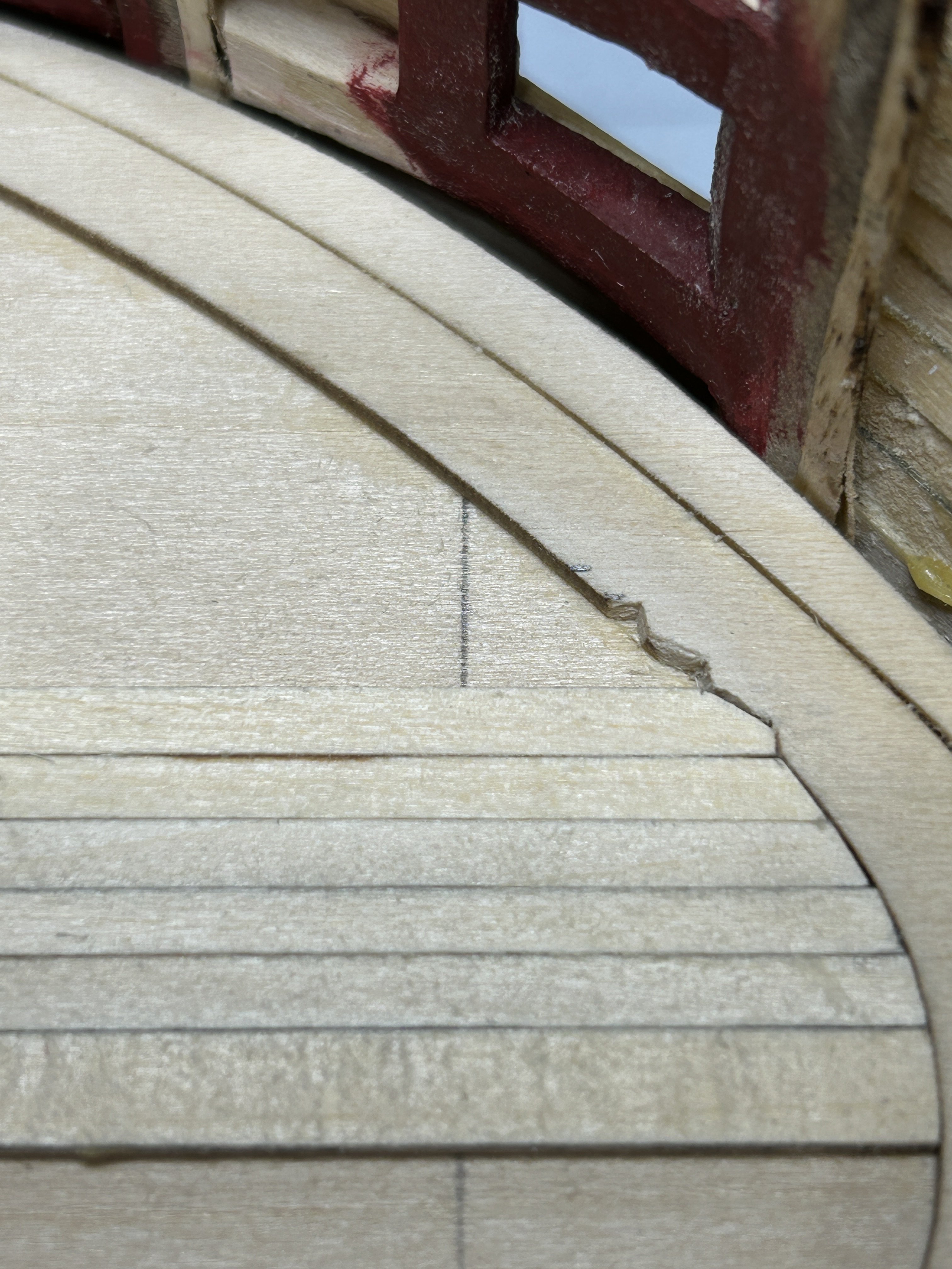
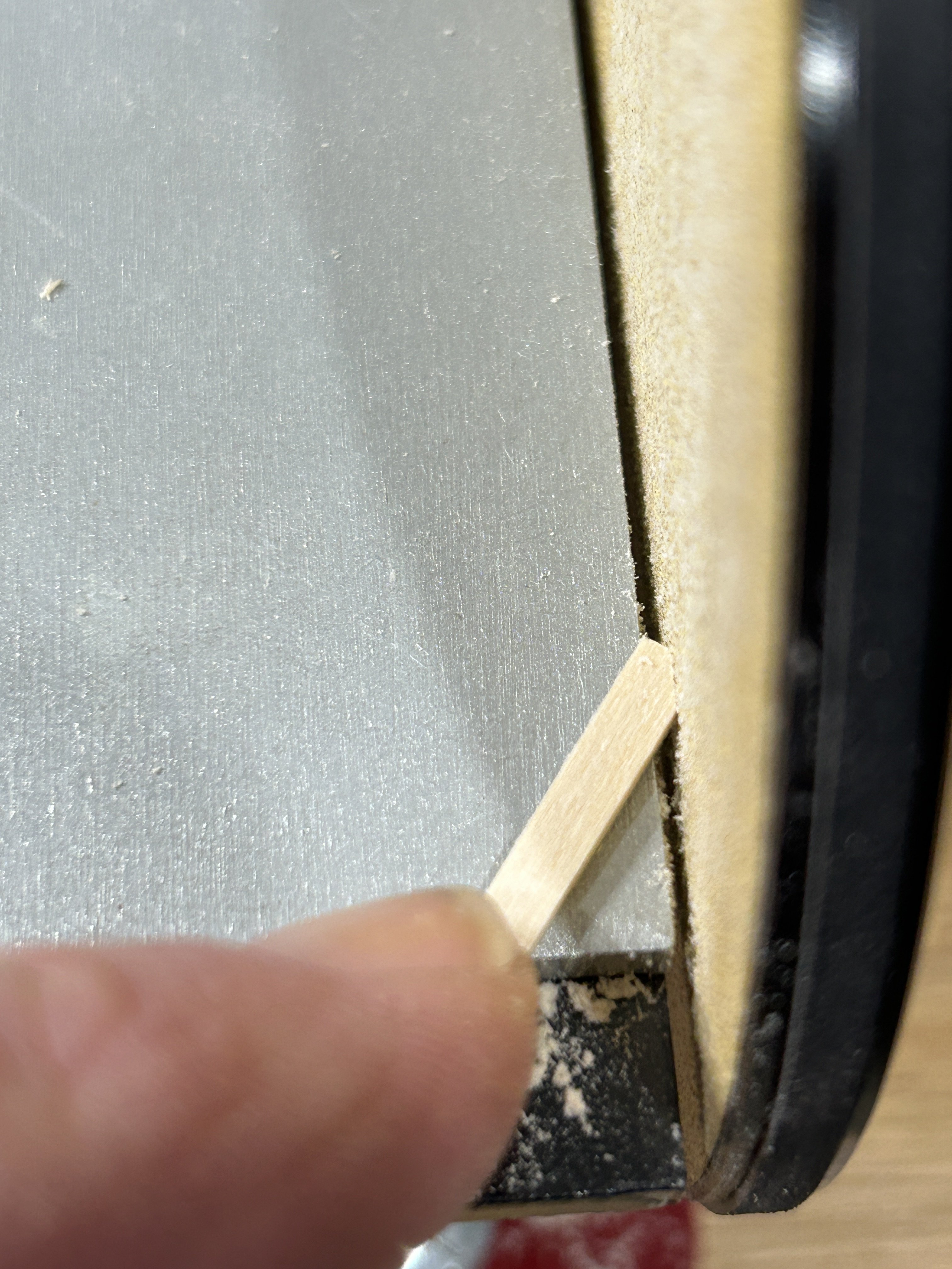
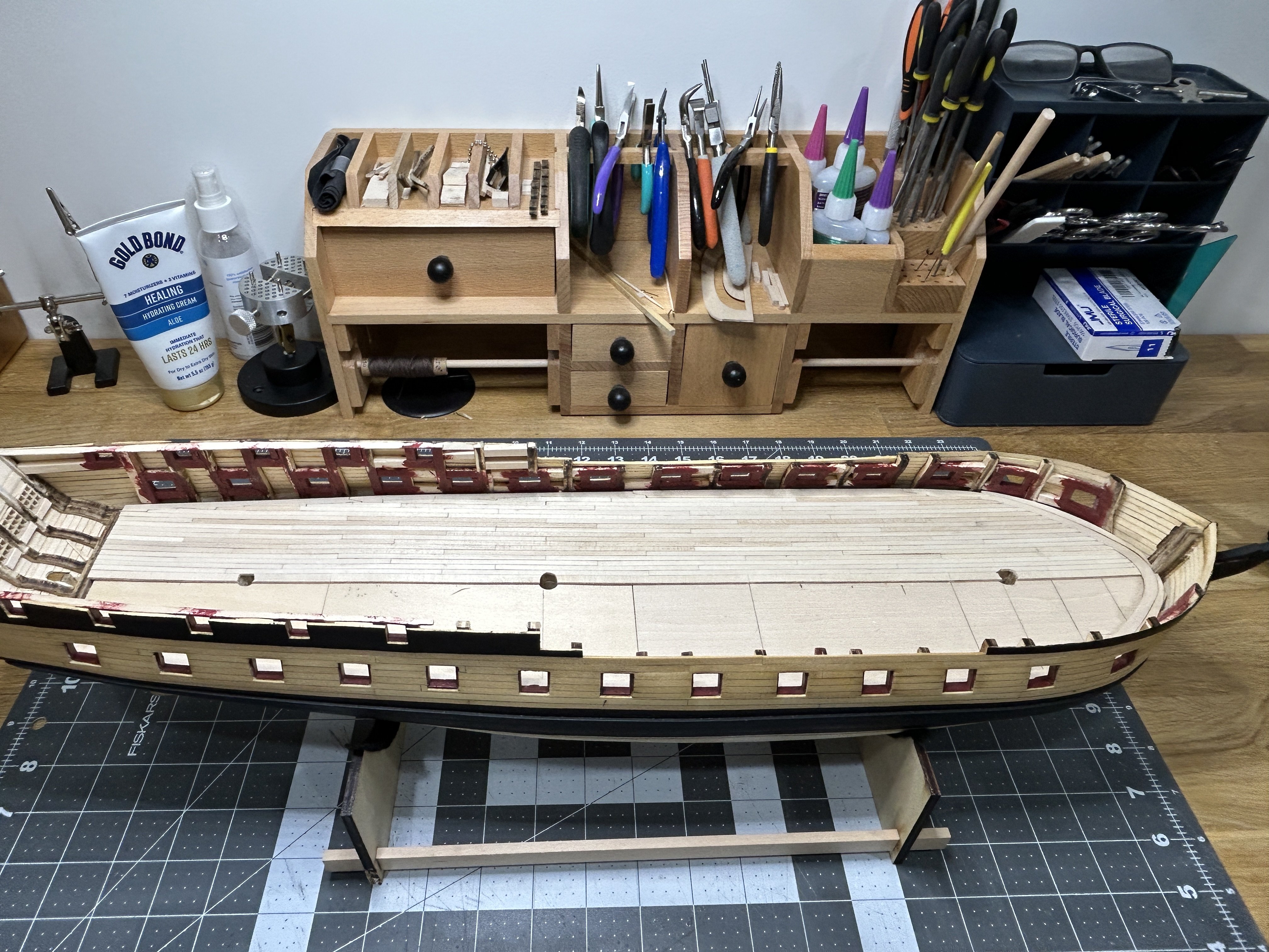
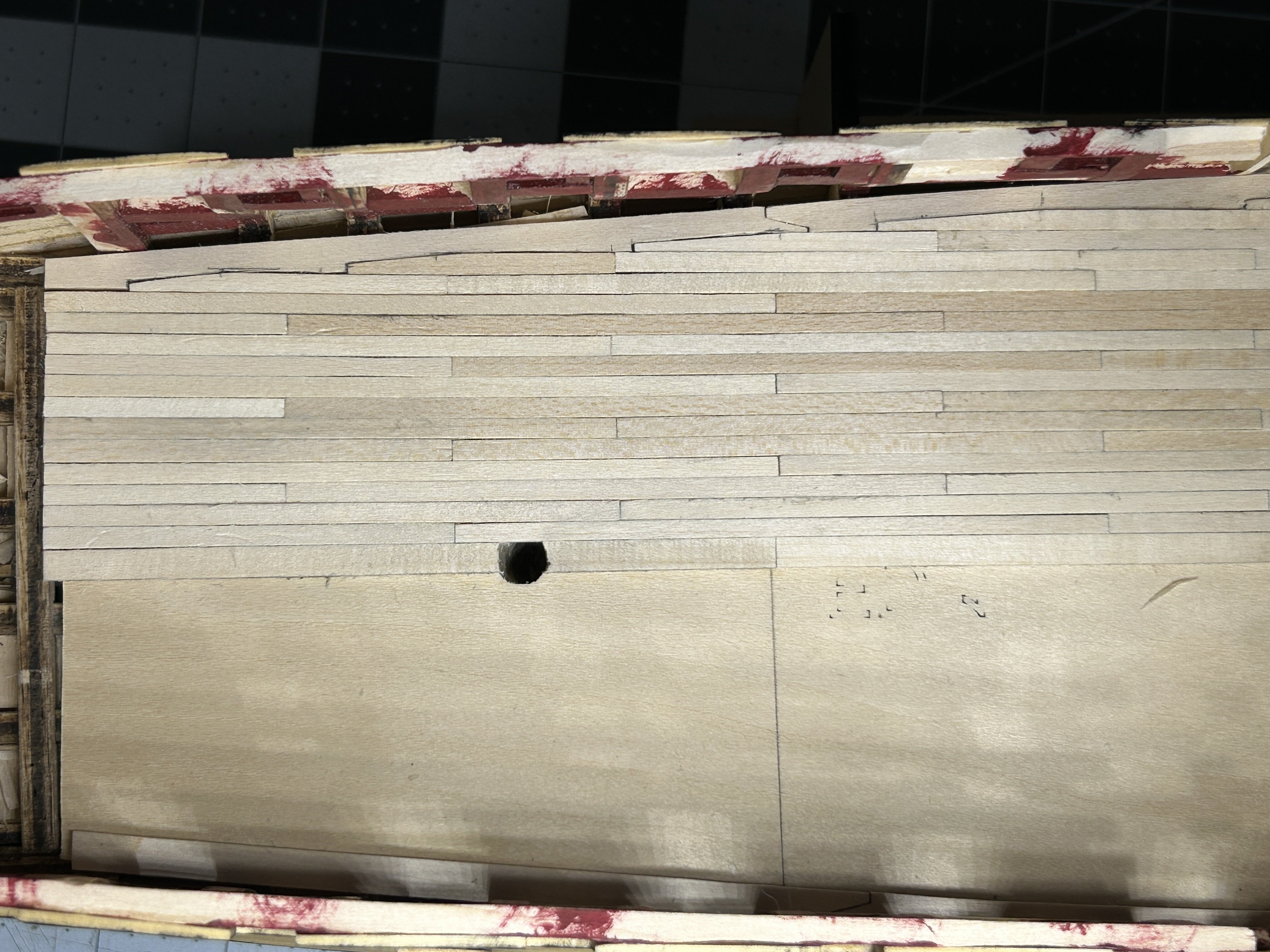
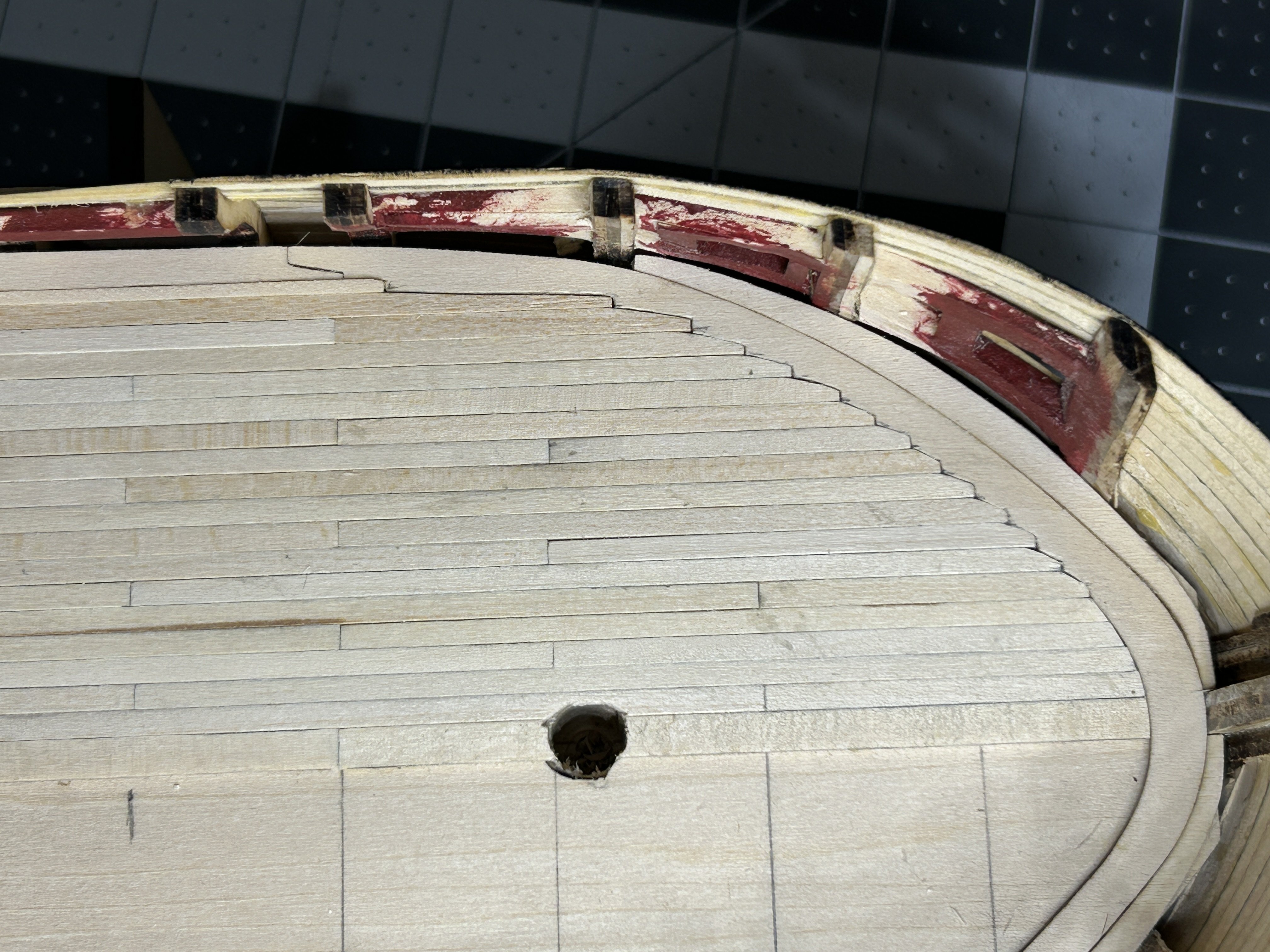
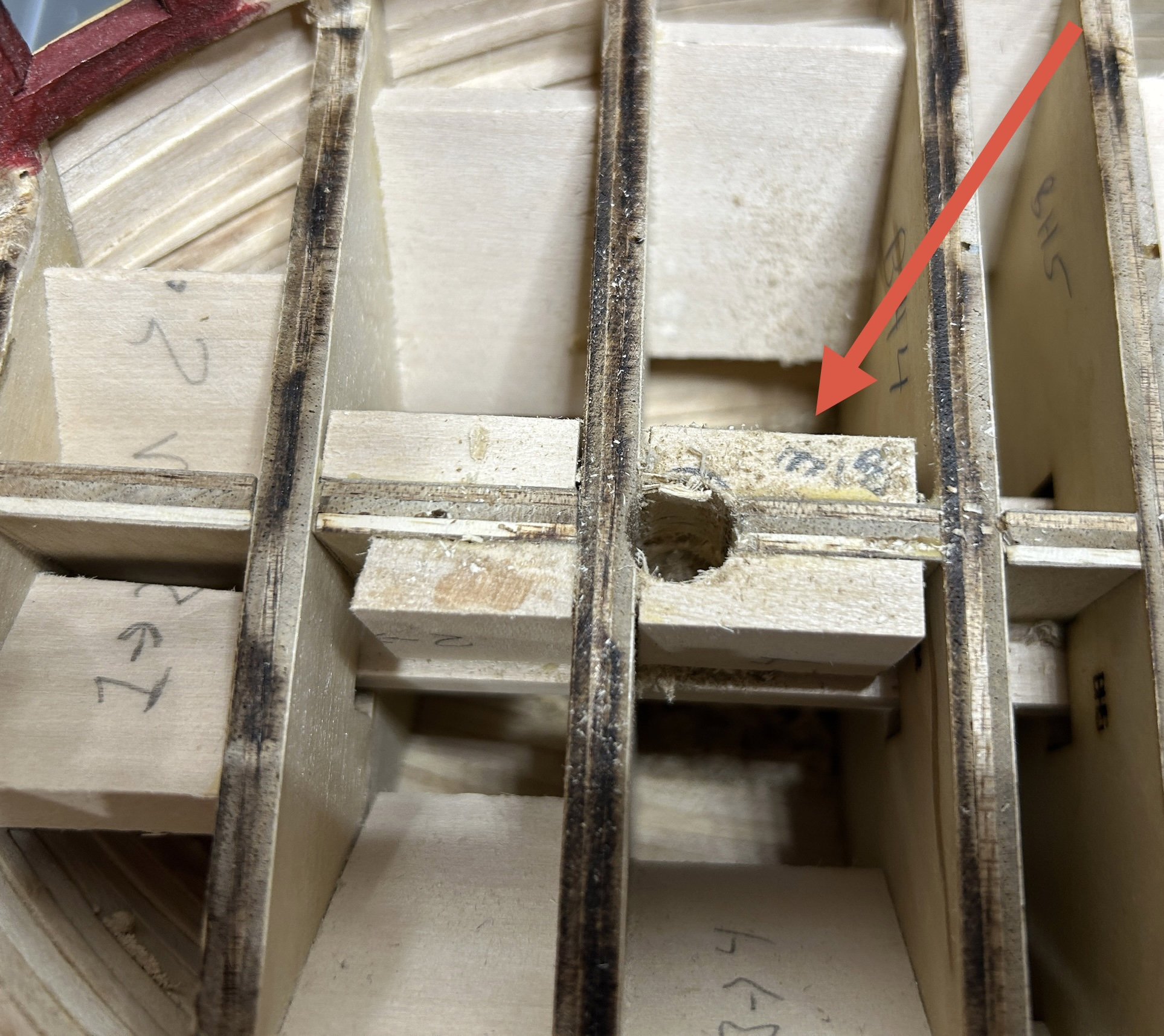
I have made significant progress on the decking of the gun deck. The first step was gluing the false deck to the gun deck. The false deck is designed to fit loosely and is not an alignment tool according to the instructions. There is a 1/16 to 1/8 inch gap along the bulwarks. I used some of my favorite weights to hold the two pieces of the false deck in place while the glue dried. I added the laser cut margin plank around the outer edge of the deck. There was recently a post on a build log for the US Brig Syren that mentioned an issue the builder had with the margin plank at the bow, and I had commented that I anticipated a similar issue with my build. It was clear that the way I faired the interior of the bulwarks would create a gap between the planking on the interior of the bulwark and the margin plank that was bigger than the waterway that will eventually be installed. I needed to add a piece forward of the margin plank. I used a piece of tape to help define the forward edge of the part that I need to create. I used the wood that the margin plank was laser cut from for the inside edge since it matched the margin plank, I only had to cut the outer edge which didn't need to be perfect since it would be hidden by the planking and waterway. The instructions call for applying all the decking in a single plank from stem to stern and to use a pencil to add the butt joints and treenails. I chose to use shorter planks to avoid having to draw the butt joints. I will pass on the treenails. I don't trust myself to be precise enough at this scale to make them look good. I made the same decision on the treenails on the exterior of the model. I chose to use 4 inch planks, which works out to about 25 feet at this scale. I added a line to the false deck every four inches as a guide and on every inch in the section near the bow. Since I was using individual planks I needed to ensure that the first row of planking down the middle of the deck was installed straight. I pinned a single piece of planking along the length of the deck and use it as a guide to add the king plank. The king plank is 3/32 x 1/16. The rest of the planks will be 1/8 x 1/16. The first four planks were angled at the bow to fit snugly against the margin plank. On the fifth plank I started to joggle them. This is my first experience with joggling planks. I will joggle the planks on the upper decks also, so I am glad I have the opportunity to do this on the gun deck first where my inexperience and learning curve will be largely obscured by other deck features and the partially planked upper decks. The image below is my first joggled plank. I worked out a process where I would only dry fit the adjacent plank (red arrow) so it could be removed to make it easier to cut out the portion of the margin plank that the plank would fit into. With the adjacent plank dry fit into place I would place the next plank as shown (green arrow) and mark to out edge and make another mark approximately 1/2 way between the edges of the planks. I would then make a cut at a ninety degree angle from the outer edge of the adjacent plank approximately 1/3 to 1/2 of the width of the plank. and then another cut that was parallel to the length of the plank. Then I would connect the right angle created by the two cuts and the mark I made at the outer edge of the blank. I used my disk sander to shape the planks to fit. I continued this process outward from the bow and then back towards the stern. I have completed the port side and I am very happy with the results. It will need a little sanding and possibly some spots that need to be filled with wood filler after I get the starboard side complete. I have really enjoyed this process. I know a lot of kits come with decks that have laser cut images of the planking eliminating the need to plank a deck like this. These decks look fantastic, but I am happy to have some imperfections in exchange for the experience of joggling the planks. I was nervous about this step before I started partially because there are no instructions that show you where to cut or how to lay out the joggling towards the stern. I took my time and everything came together fine. I will be getting started on the other side and then get it sanded, stained and sealed.


-
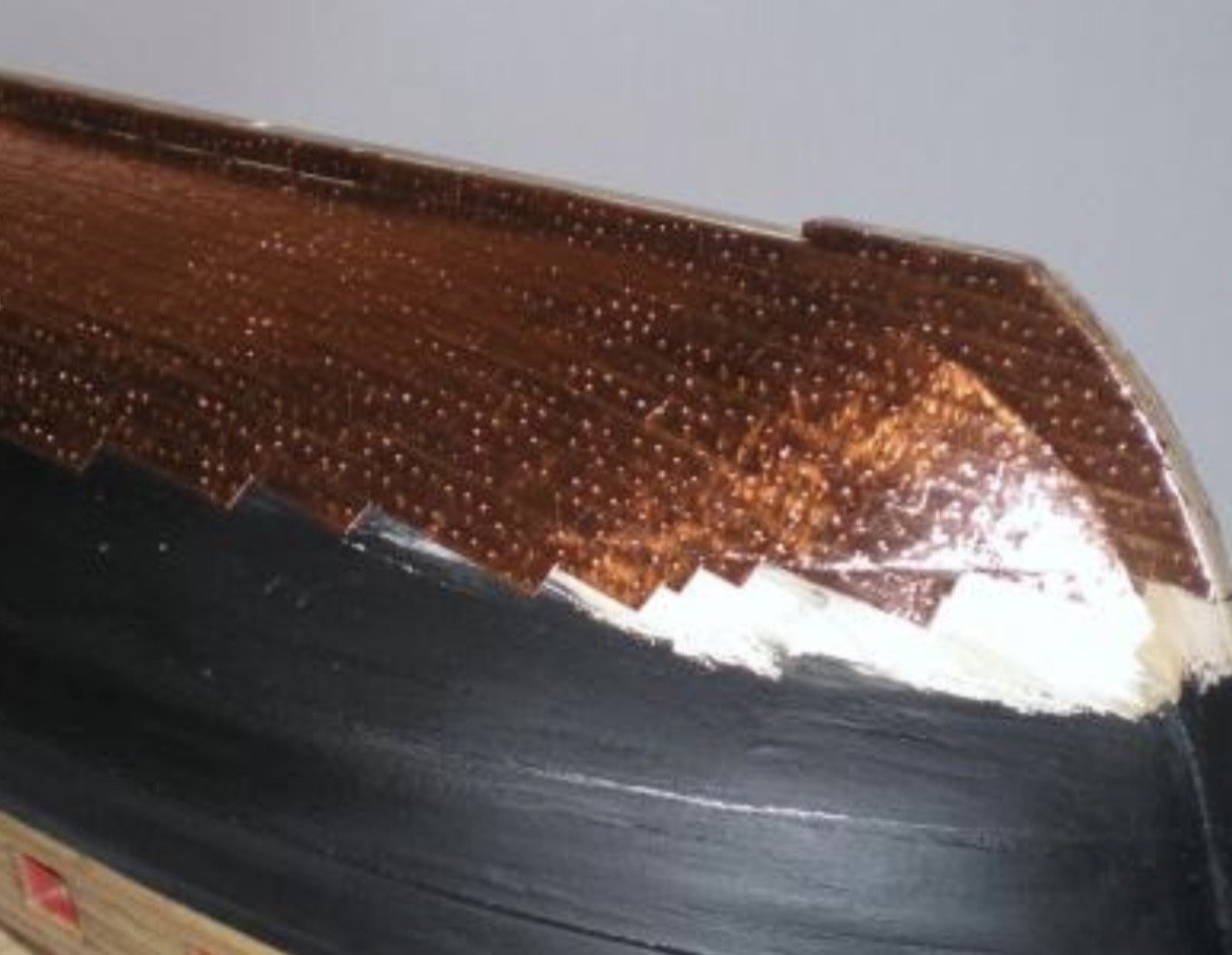
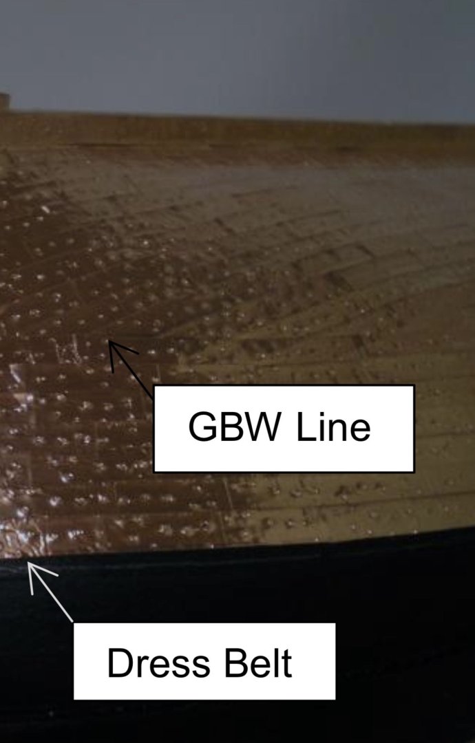
The instructions refer to it as the gore belt line. It is a line midway up the copper where the curve in the plates that is created by the shape of the hull is straightened. Here are a couple picks from the instructions that show what I mean.
-
Cutters, Choppers, Guillotines, Slicers
RossR replied to MintGum's topic in Modeling tools and Workshop Equipment
I do the extra square cut on all my work with the slicer. I find it worthwhile because it gives such a clean square cut. I was using it today to cut 1/8 x 1/16 deck planks. I was cutting about 25 planks planks with an extra square cut at each end in about 5-6 minutes. The stop allows about a 10 inch length. I am not sure if there is an extended version. -
Recommended First Machine
RossR replied to vvvjames's topic in Modeling tools and Workshop Equipment
You will use a disk sander for every phase of a build except rigging. Can't go wrong with that choice. -
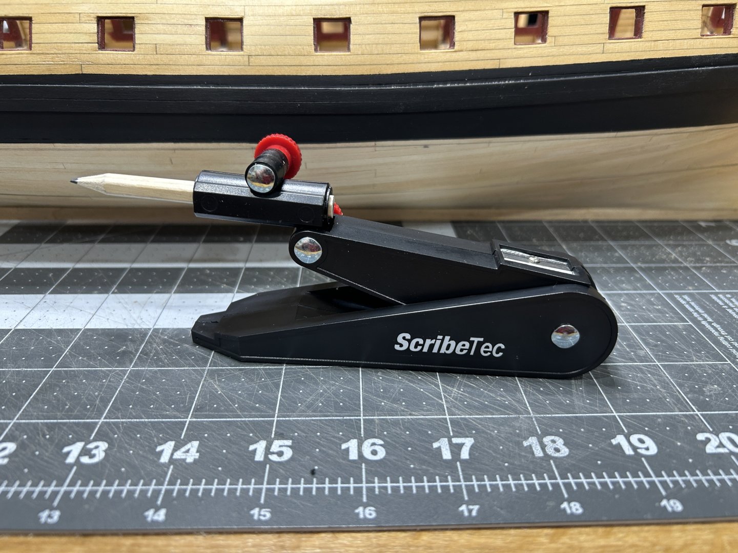
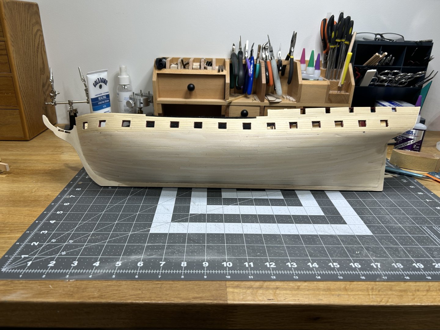
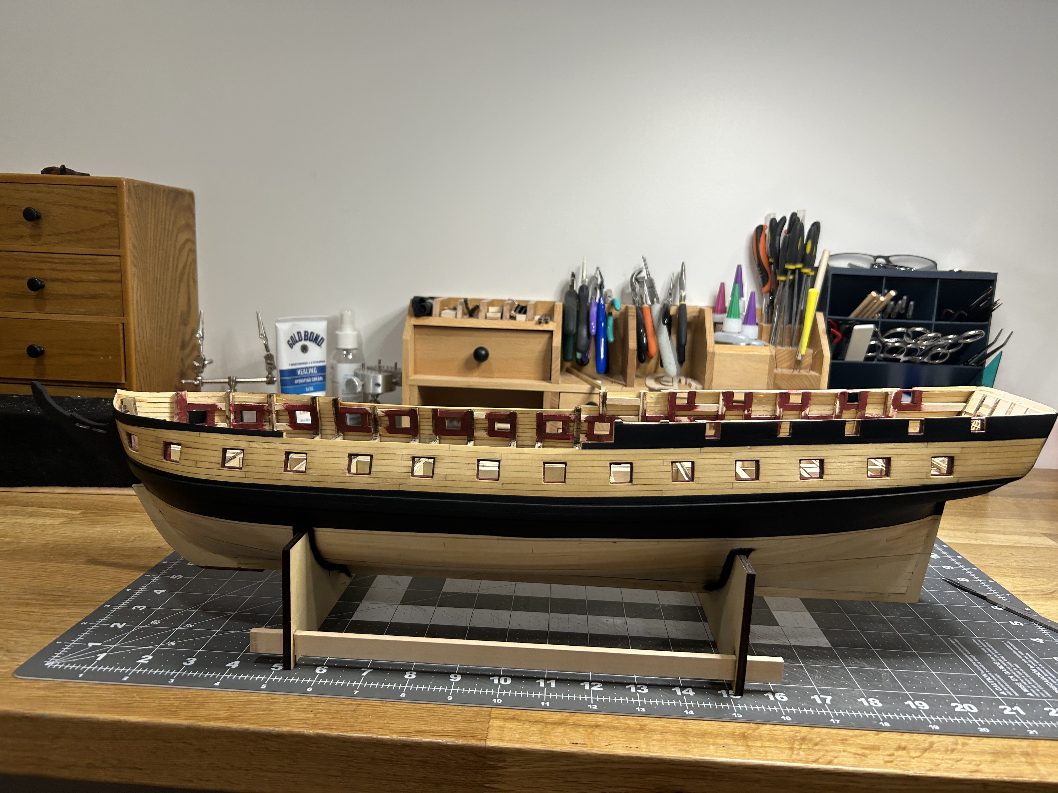
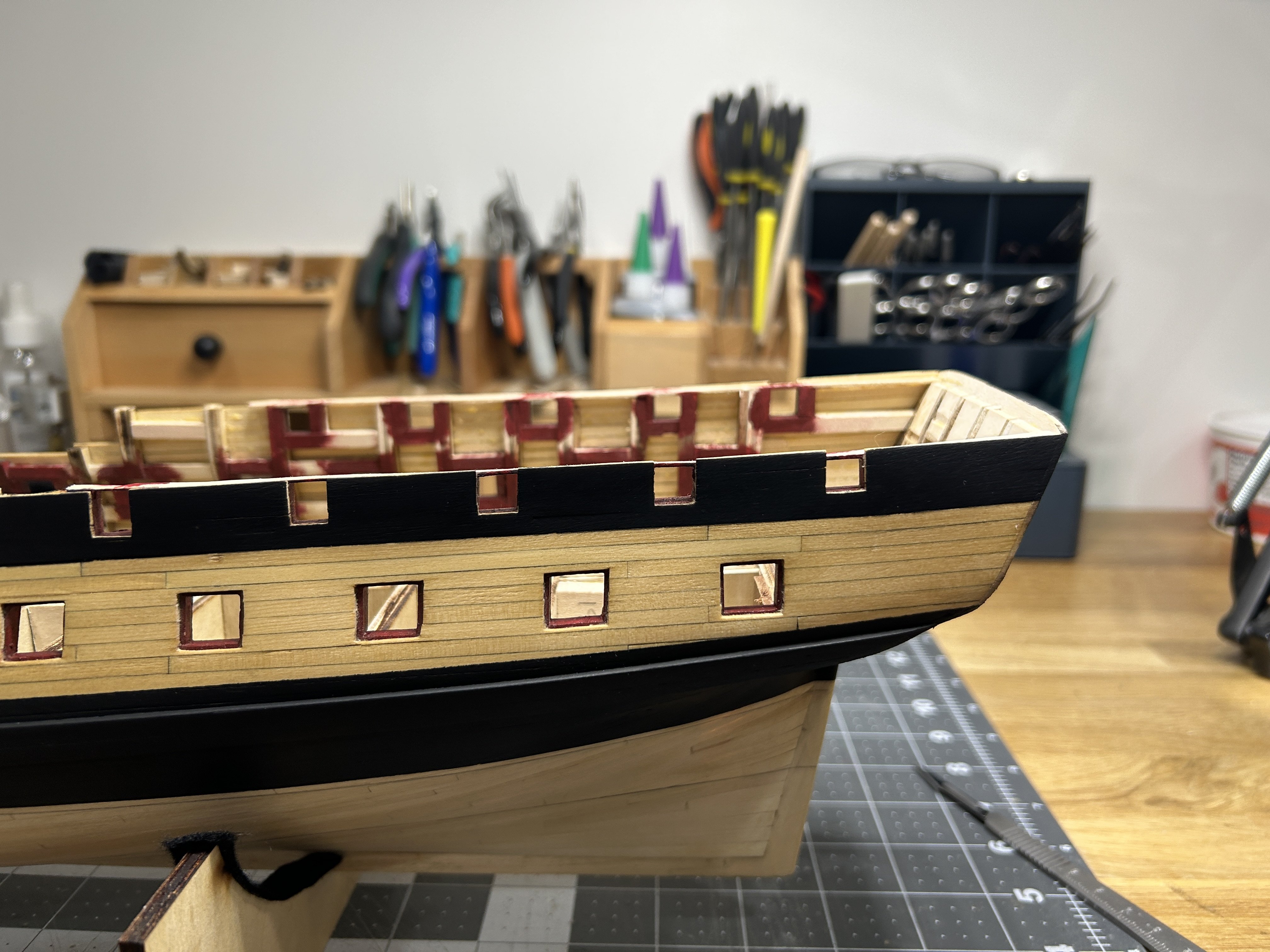
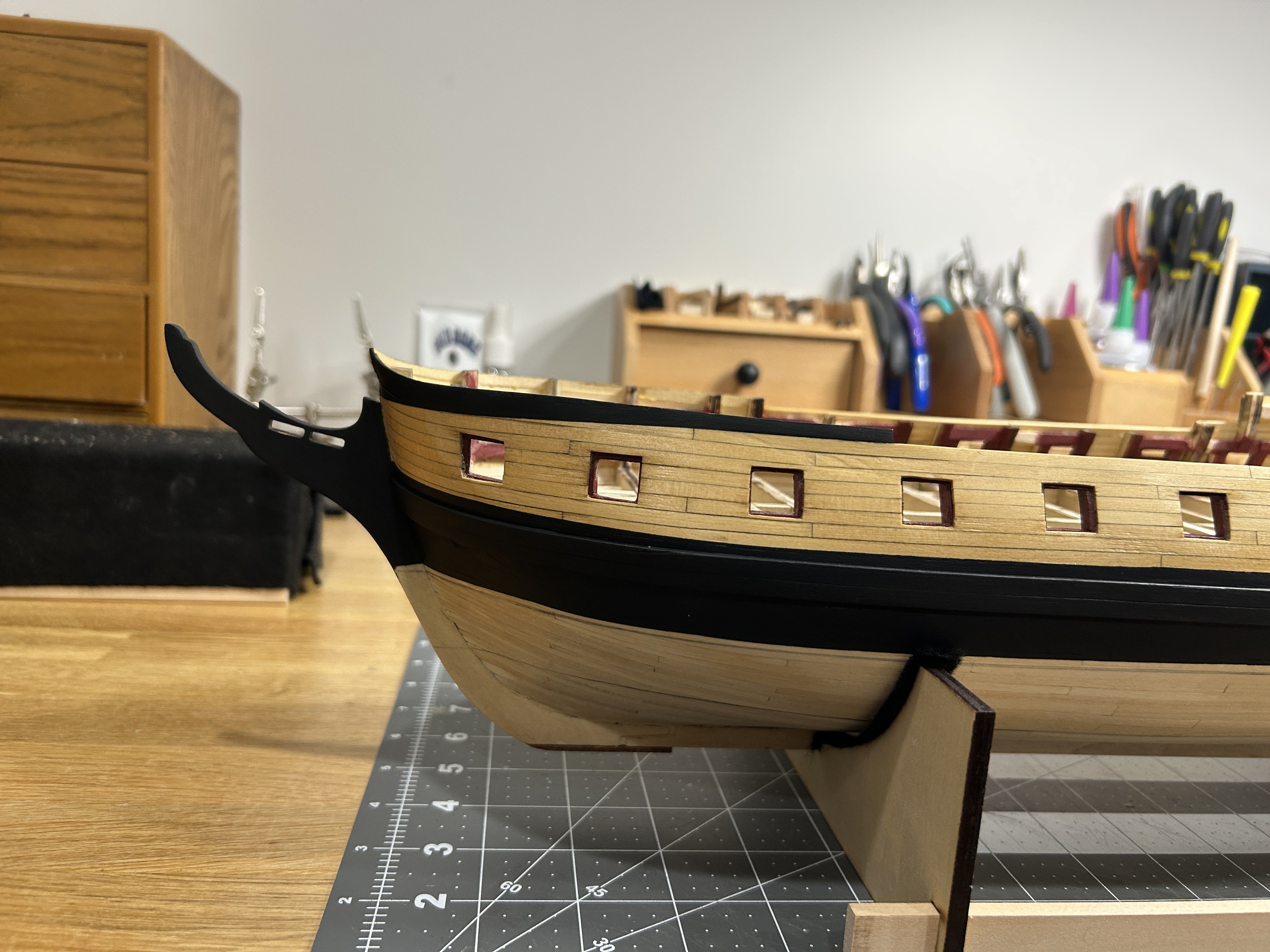
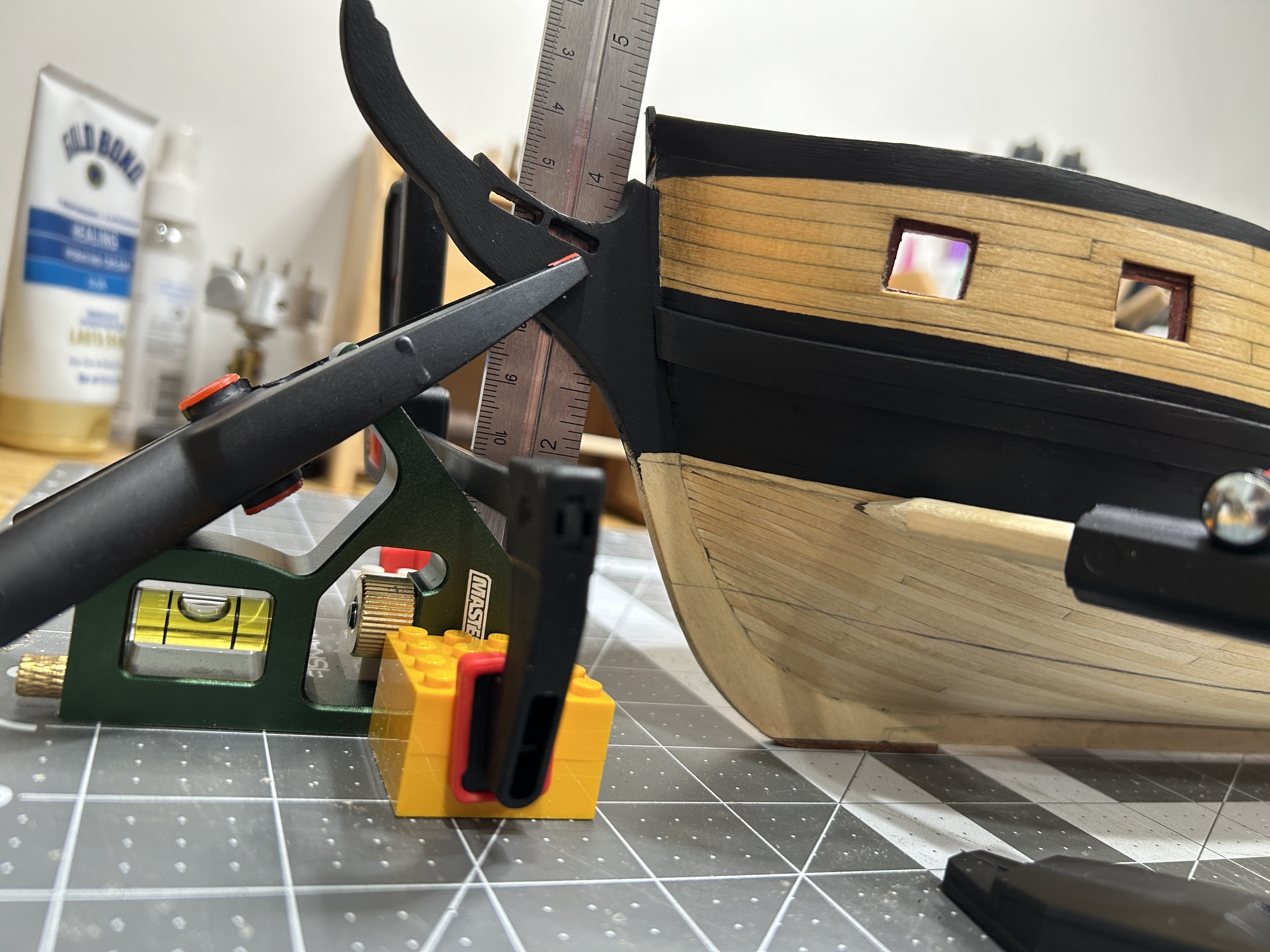
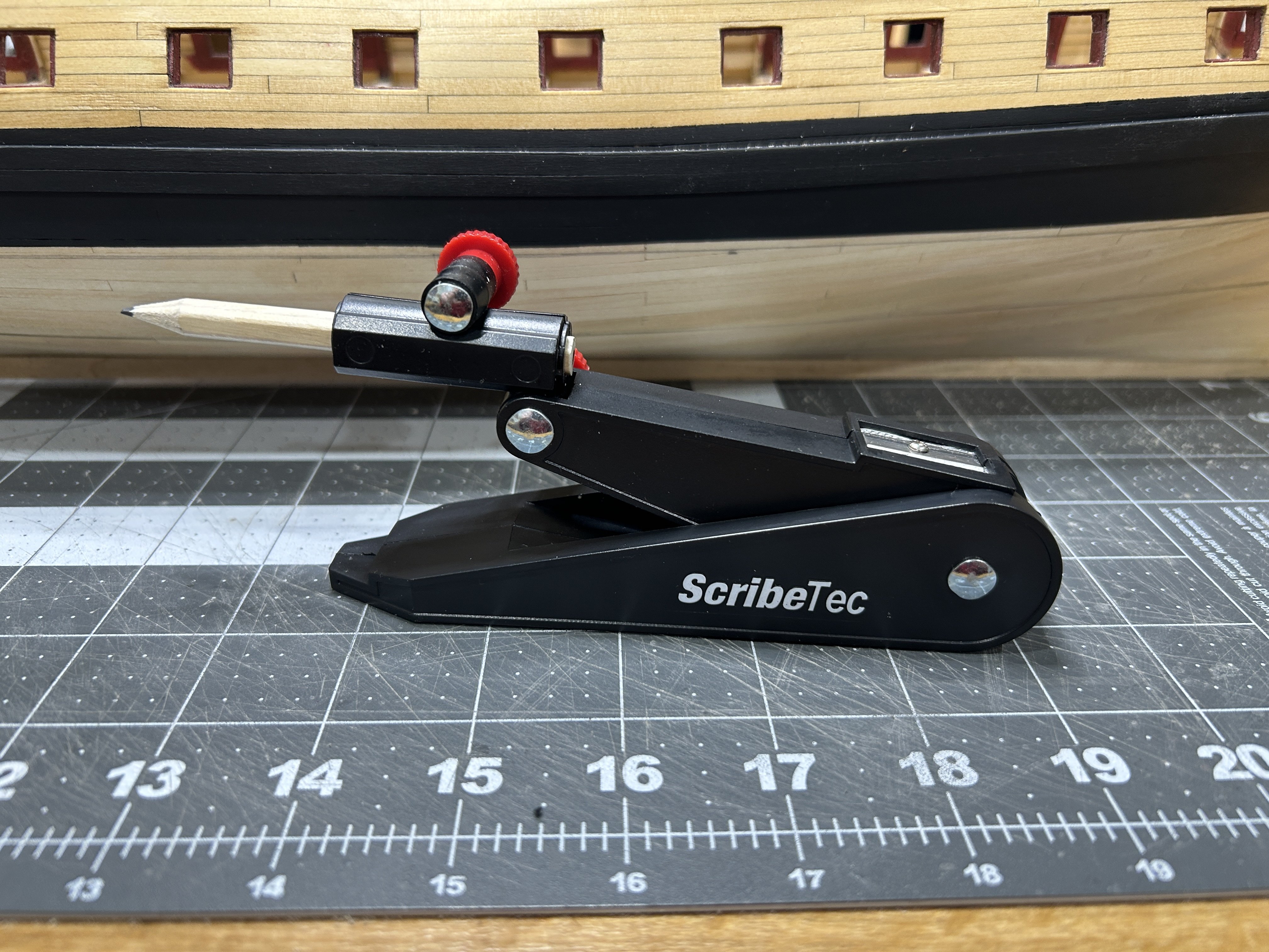
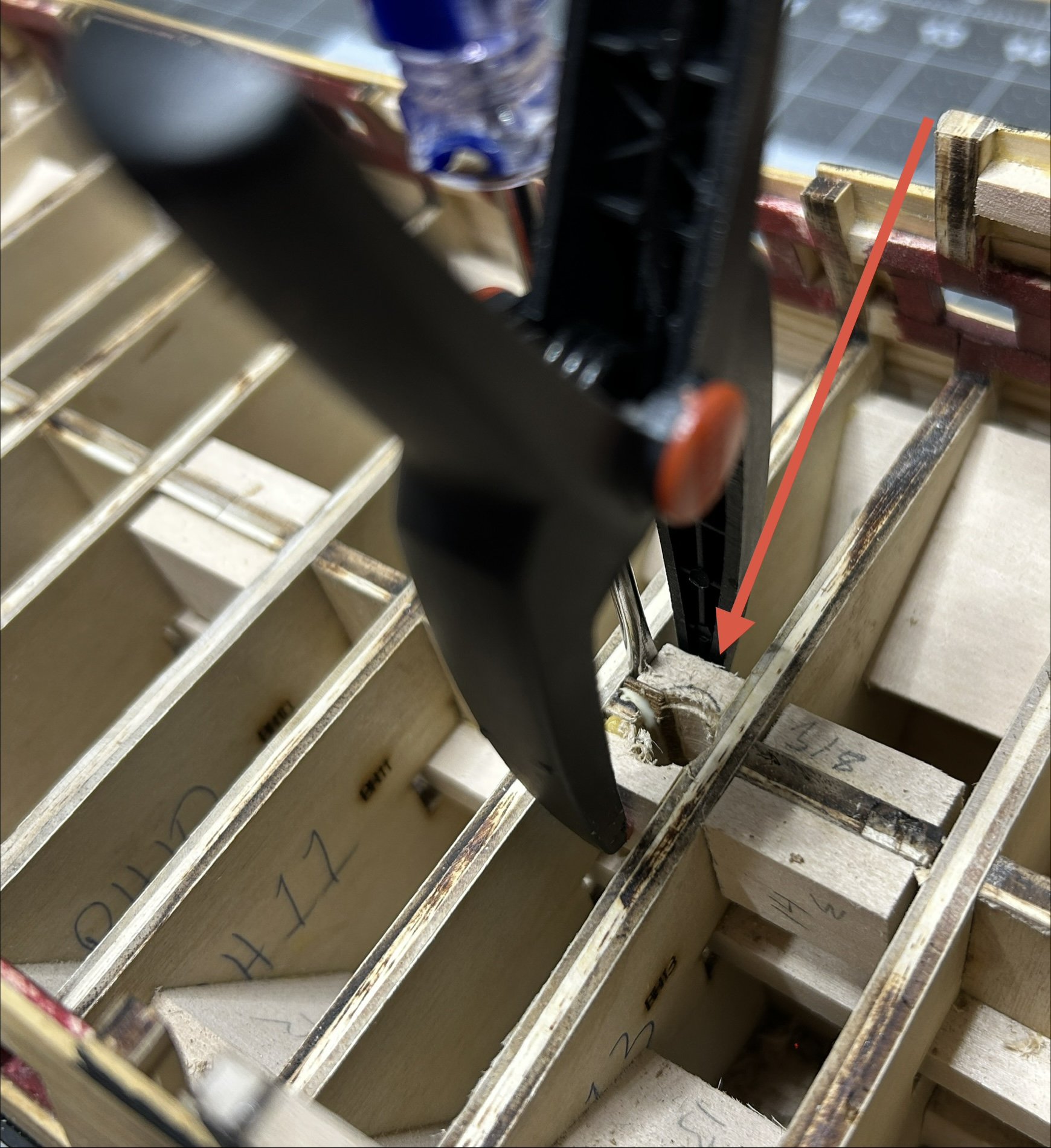
I have added the finishes above the copper to the exterior of the hull. I used some Minwax Pre-Stain on the area around the gun deck and then applied some Minwax Honey Oak stain to give it just a little more color. I then gave the whole exterior a coat of shellac. This will serve as a sealer under my paint and a coating for the natural finished portion. I added black paint above and below the area with the natural finish. and on the stern. The copper bottom has a dressing belt at the top. I painted the black down so that row should overlap the black paint by about half the copper plate. these pictures are taken with the ship in is building cradle for the first time. I didn't get any pictures of how I made the lines for the top of the copper section and the gore line of the copper plates, but I recreated the process in a couple of pics after the fact. There are plenty of commercially available tools for making these lines on the hull and we have seen many homemade versions as well. I used a carpenters scribe tool. This is used by finish carpenters and cabinet makers to mark various lines when trying to fit something to an uneven surface. I found it worked fantastic for marking the lines. To hold the ship straight upright I used a small combination square clamped between a couple of Legos to give it some additional stability and then clamped the ruler to the stem. It all worked pretty well. Next step is drilling the holes for the masts into the bulkhead former before the gun deck is installed. I hate the process of drilling into the edge of a piece of plywood. I find that is wants to split as you drill. I ran into this with my first two Occre models that require you to drill a hole for the bow sprit. Occre provides cutouts for the masts which is great. The Essex requires a hole be drilled for each of the three masts. the instructions have you glue extra wood to the bulkheads former to provide more material to drill into since the diameter of the masts are thicker than the bulkheads former. Unfortunately I glued this material to the bulkhead former and not the bulkheads. When the bulkhead former split there wasn't enough material left glued to the bulkead former due to the small distance between the bulkheads. I have had to re-glue the material and make sure it is glued to the bulkheads not just the bulkhead former. The only hole that went will is the foremast. This one had more distance between the bulkheads and the extra material held.


-
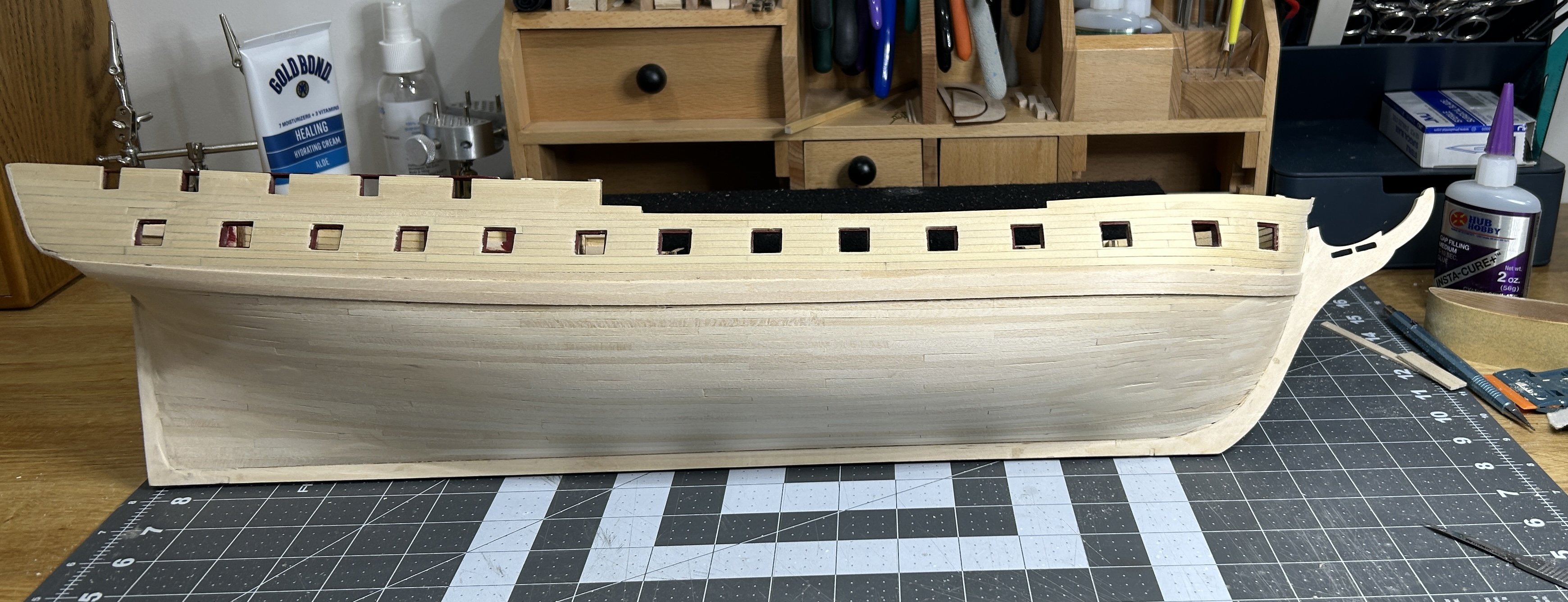
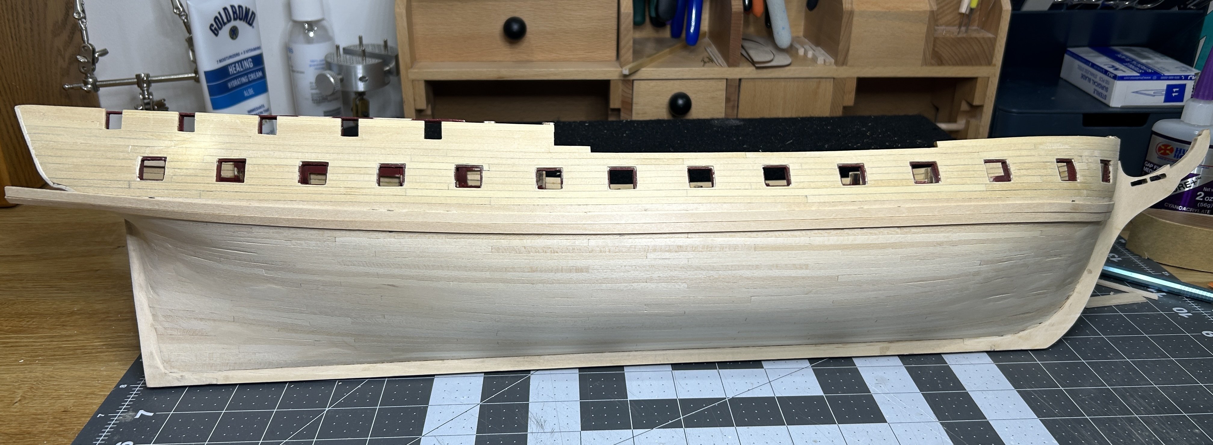
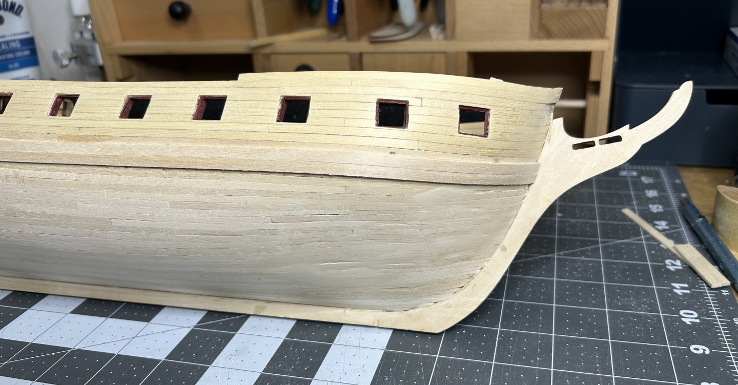
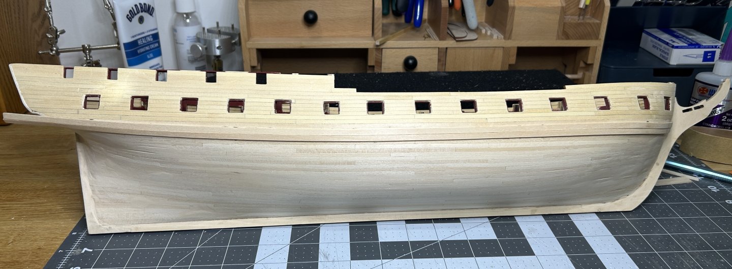
I was able to complete the sanding and filling in any gaps. I was actually surprised by how few gaps need to be filled. I used a used a disk sander on a Dremel to start my sanding. I used a 120 grit for areas that had more material to remove, but quickly moved to a 240 grit the smooth out everything. I then used a series of three progressively finer sand paper by hand to really smooth things out. After sanding I started adding the wales. The wales are made of two strips of 1/16 x 3/16 inch basswood. After sanding the wales I am really happy with the results. I used a 4 inch section of PVC pipe to form the curve in the planks at the bow. I still need to add the wale on the other side, and then I will work on finishing the area above the copper. Black paint directly above the copper and then a natural finish at the level of the gun port and then more black at the quarter deck and forecastle. The next couple of days will be pretty busy, but I have boxing day off and hope to get 3 days with lots of time in the shipyard before heading back to work on Monday.
.thumb.jpg.62e59da49563297d7aad1a046b1f8ce9.jpg)
.thumb.jpg.1edd43e5d34181ed3b3ea23cbee2e4df.jpg)


-
Thanks. I don't have a build log on my Beagle. I discovered Model Ship World as I was finishing that build. There are a lot of logs for the Beagle on the forum. Many of them quite good.
-
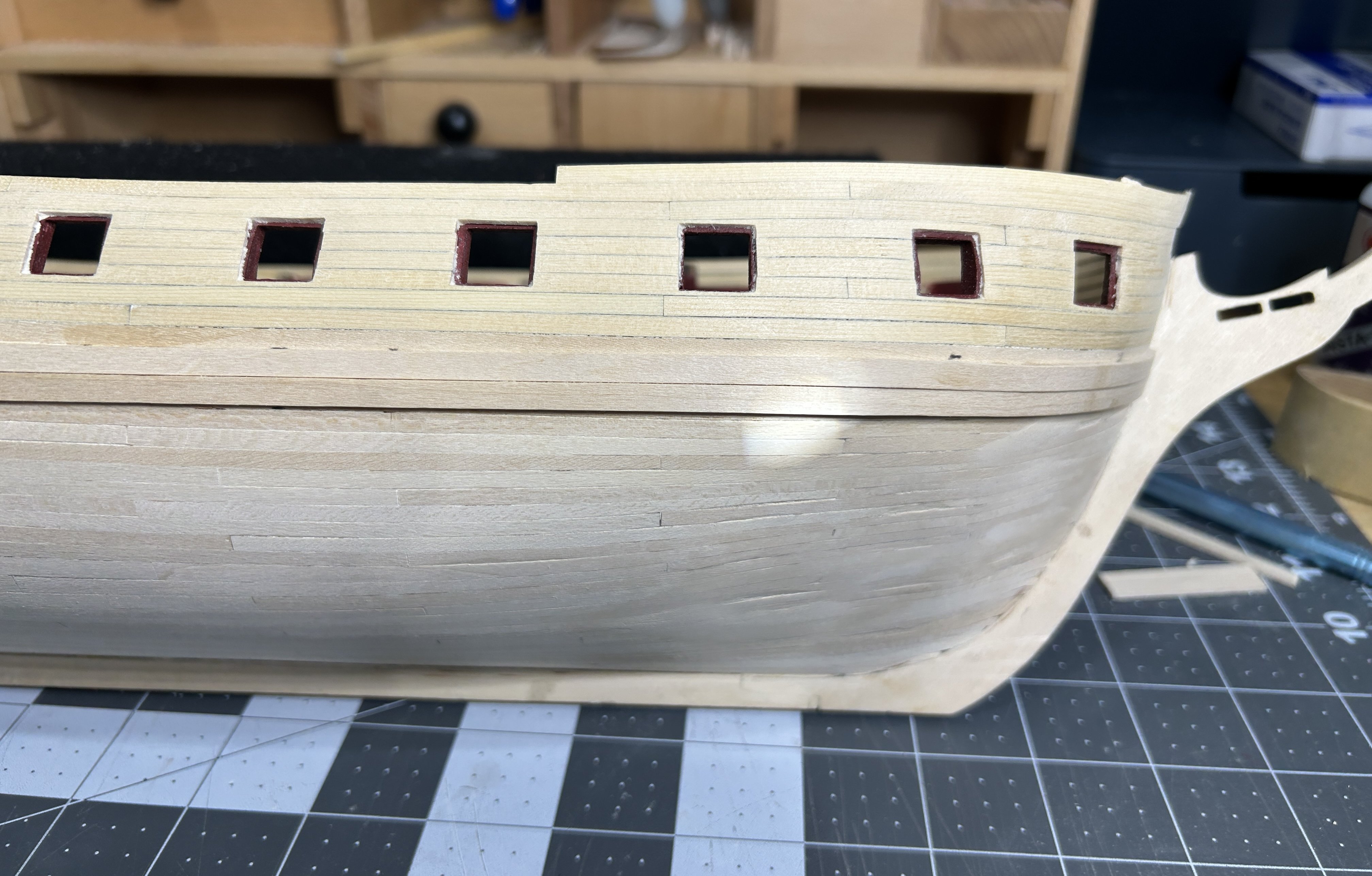
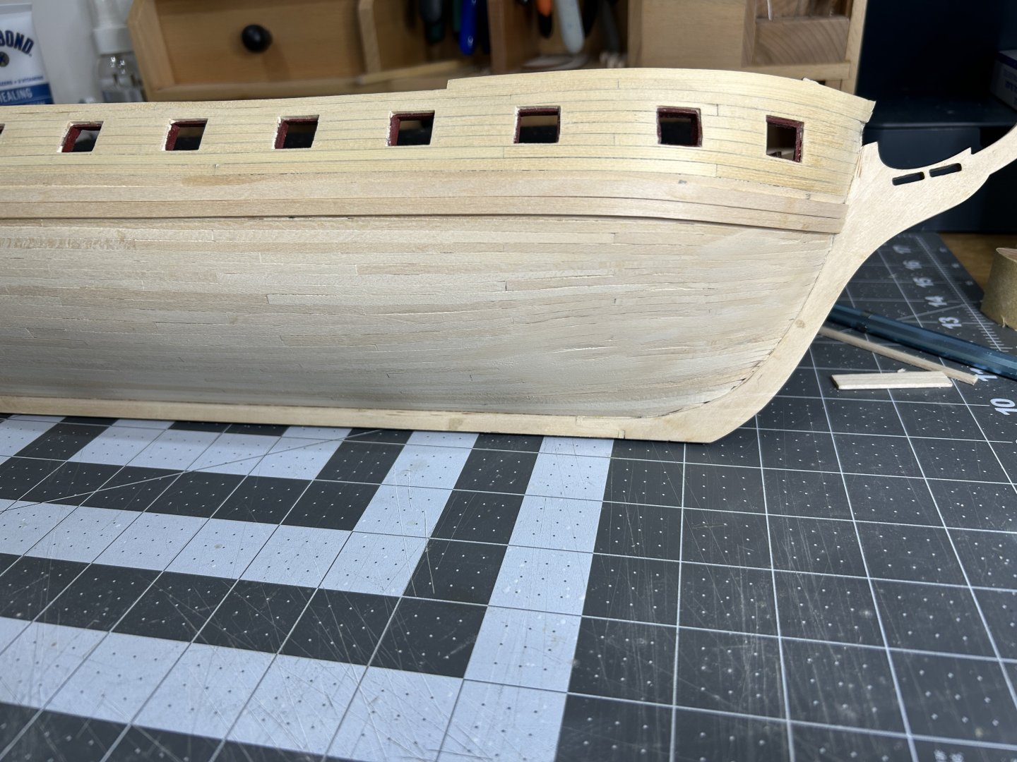
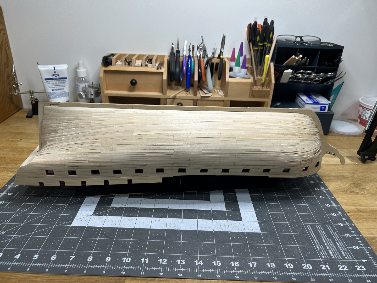
I have all of the planking installed now. It is far from perfect, but I think I made a lot of progress with the edge bending process. I was able to get the temperature of my wood burning dialed in so that it didn't scorch the planks but provide plenty of heat to allow the wood to bend. I also improved at shaping planks that needed to be fit exactly into an opening or fit tightly to the plank above or below. It is far from perfect, but I am happy with how much I improved as I went and I will have a lot more confidence if my next build has a hull that isn't painted or coppered. I still need to do quit a bit of sanding and then some filling in a few spots. I usually do my heavy sanding in the garage due to all the dust. It is 6 degrees Fahrenheit / minus 14 Celsius right now, so I may wait and hope it warms up a little this afternoon. After the hull is sanded and the gaps are filled I will be adding the wales. The instructions then have you add the exterior finishes that are above the copper plates. After that is is on to the decking on the gun deck. This will be my first time joggling planks. I am Looking forward to that step.

-
Joggling Deck Planks
RossR replied to DGraley's topic in Building, Framing, Planking and plating a ships hull and deck
I am close to the step on my USF Essex. This was very helpful. Thanks. -
Fund raising
RossR replied to Russ2025's topic in Using the MSW forum - **NO MODELING CONTENT IN THIS SUB-FORUM**
I used the “Donate Now” button near the bottom of the home page yesterday and it worked. I think some people might be trying to click on the banner at the top of the home page. -
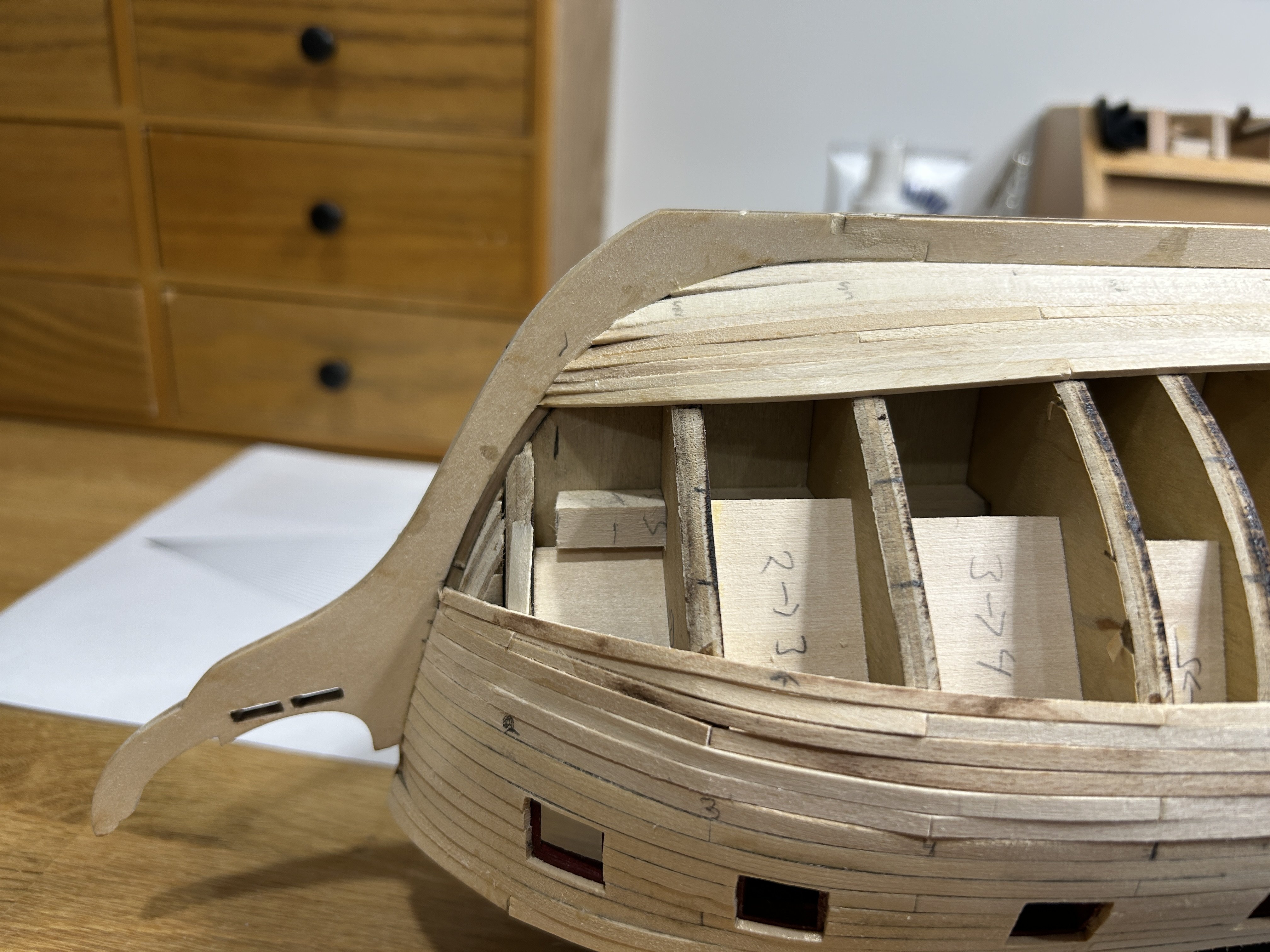
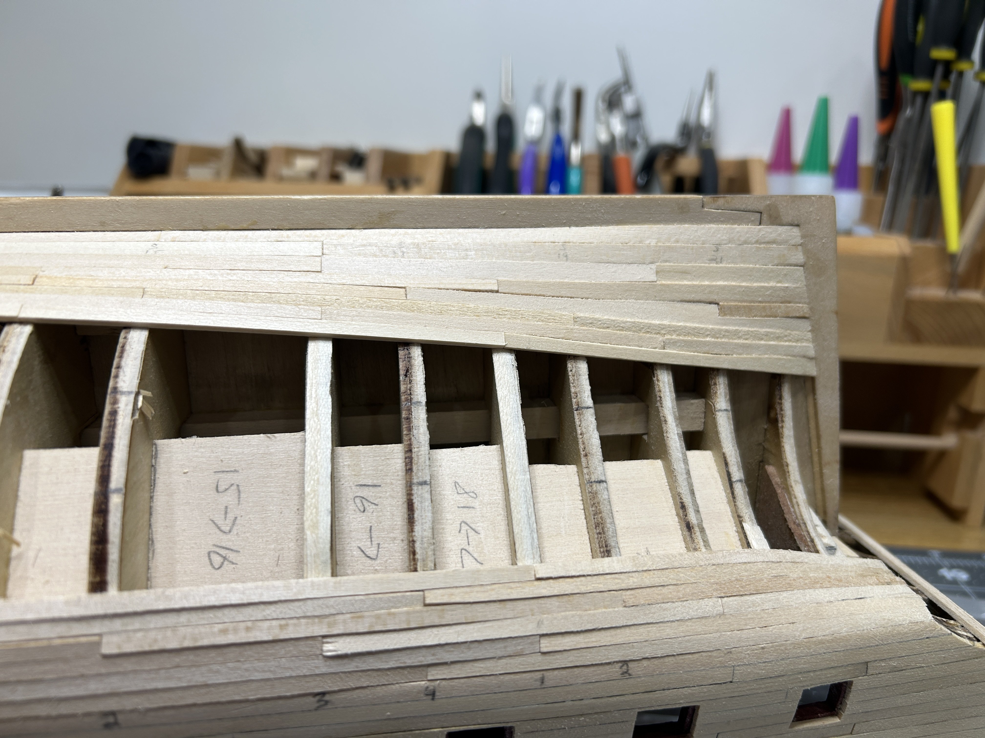
I have the next band of planking added to each side. As I mentioned on my previous post, I didn’t do a good job of keeping both side symmetrical. I started the next band on the side that has the Garboard strake curve too high on the bow. Not surprisingly that is creating challenges. On the other side I am happy with my progress. I have the heat dialed in better on my iron for edge bending and I am getting better at getting the planks to meet up with no visible gaps on the tapered planks. These pictures on on the second side that I planked, the one that is turning out better. I hope to have all of this ready to start sanding in a couple weeks.


-
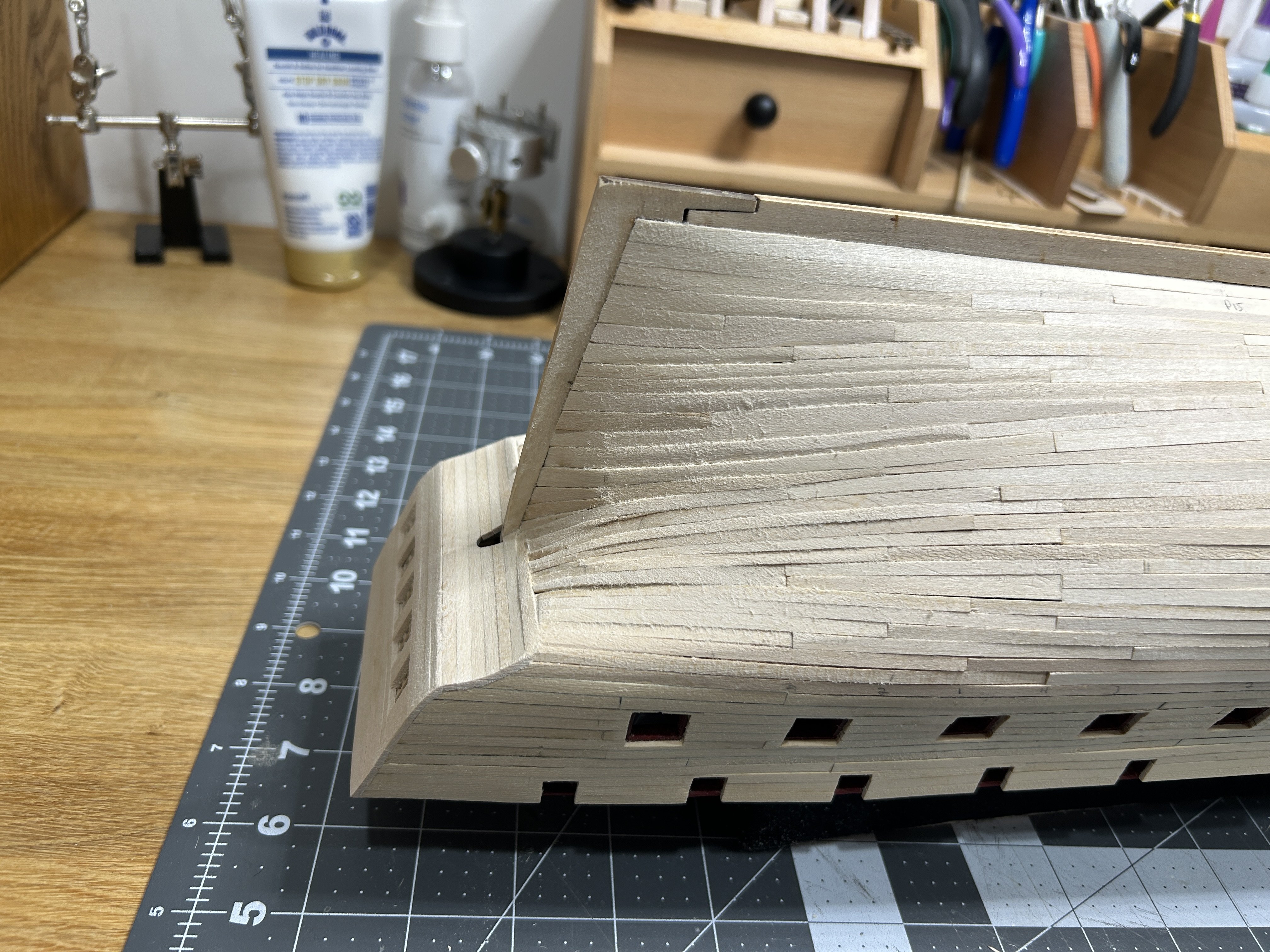
I have made some progress on the planking and have learned some lessons. I am not going to stress too much on the issues I have, since all the planking I am currently adding will be painted or covered with copper plates. My previous model that was "properly" planked was a half hull. I realize now that I didn't do a good job of making the initial planking on the port and starboard sides symmetrical. on the Garboard strake I have too much curve up the bow on one side, the other I think I did a good job, and on the upper planking I didn't do a good job of getting the planking at the same height on the bow. As I said I am not going to stress on these issues and they will be painted or covered in copper, but I do want to note them and hopefully learn from them. I have the remaining planking divided into 4 belts. I have completed the upper belt on both sides. I am using a pattern that staggers the butt joints that repeats every fifth row of planking. This is my first attempt at edge bending a plank. I needed to decide on a heat source for the bending and I already owned a wood burning iron with the following tip. I thought the shape would work very well but the wood burner would be way too hot. I had a dimmer switch in the tool box in my garage that was left over from a home project, so I put this together to dial down the heat. It has taken me a while to figure out the ideal temp, but I am making progress. I am using tape to get a visual representation of the curve I need and using that as a guide to use when bending the parts. I put the tape with the curve drawn on it on my bench and clamp a small curve peice of wood that is used to create the curve on the planks. I added a drop plank also. for the plank below the drop blank I used a similar technique with the tape to create the template used to cut out the plank below the drop planks. I hope to improve with my technique as I complet3 the planking , but thankful that all of this will be painted or covered in copper. You can see I had the temp a little too hot on my heat source for the bending on some of these planks. I will keep working and plan to post another update after the next belt of planking is added.


.jpg.f92267f7c9c9df37fd3bdad2bb753730.jpg)
.jpg.bedad988427ac6e3e9e208e2b29bbfff.jpg)