


3DShipWright
-
Posts
203 -
Joined
-
Last visited
Content Type
Profiles
Forums
Gallery
Events
Posts posted by 3DShipWright
-
-
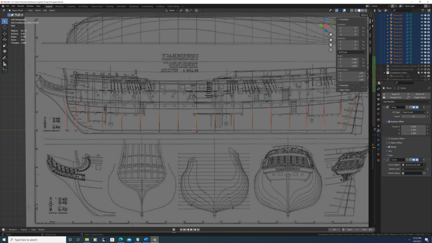
Step #2 (Continued)
So what I want to do is
1. Draw additional curves that mark the top and bottom of the main wale, the bottom of the channel strakes, and different levels of planking.
Note: I DO care about inflection point s in the overall run of the planking. I DO NOT care about things that are cut into the planking such as gunports or sweep ports.
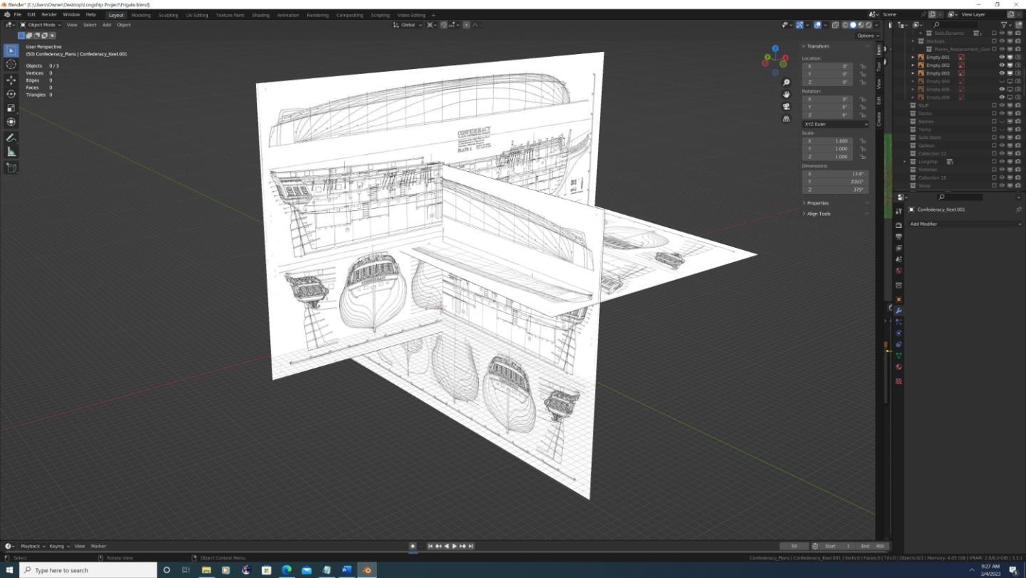
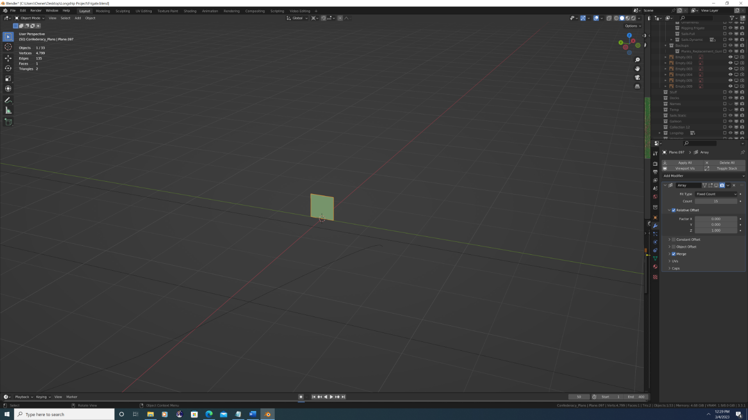
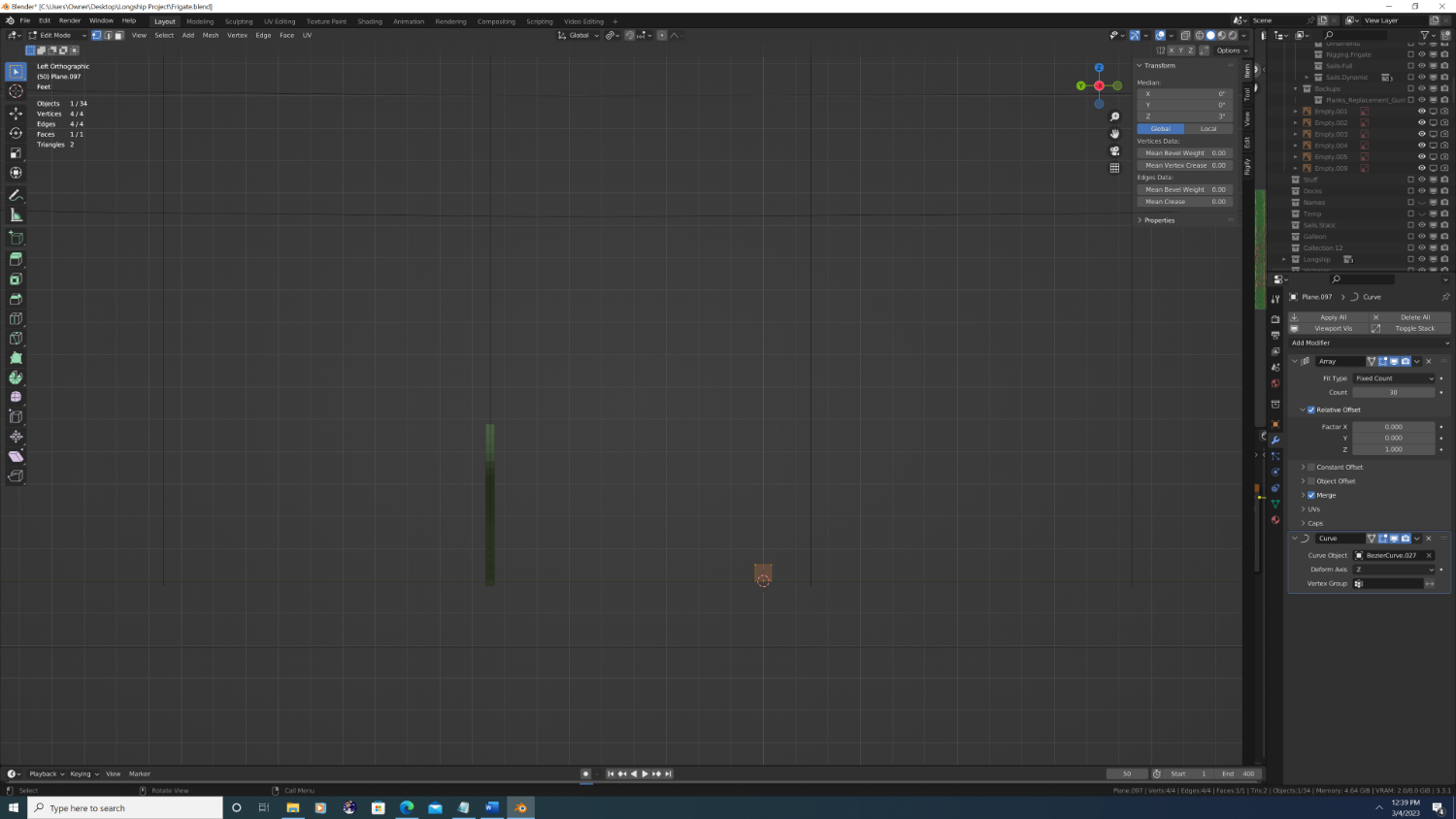
2. I added a 2D plane (6in X 6in), rotated it upright with the bottom edge flat at location z=0
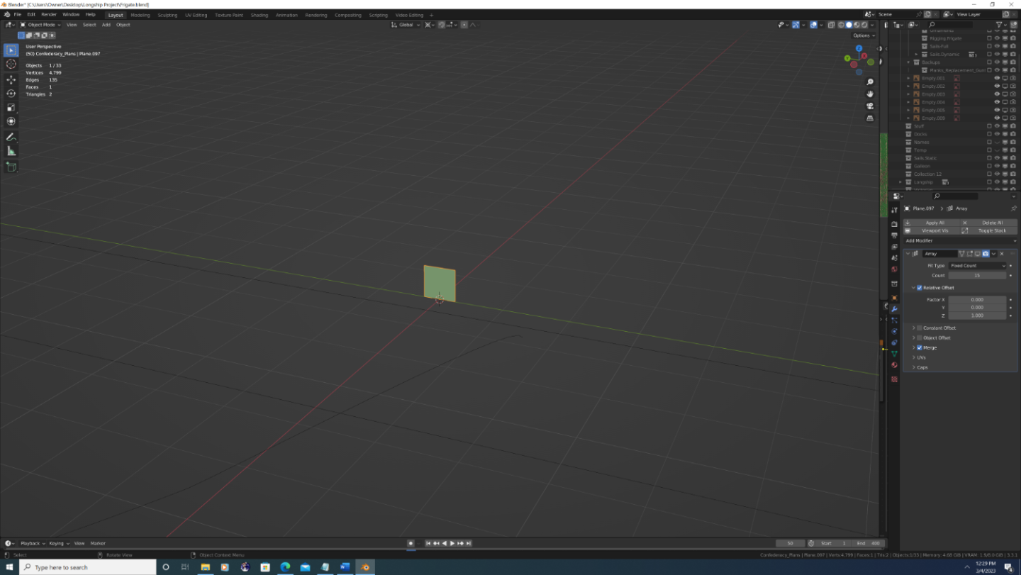
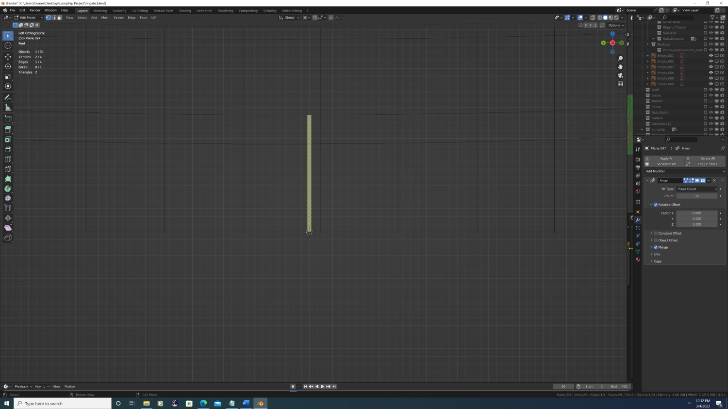
3. I then added an array modifier (z-axis) equal to the number of strakes in that section (My research conflicted a bit here as my sources showed anywhere between 25-30 plank strakes from lapstrake to bottom of the main wale) I went with 30, under the assumption that it's easier to later subtract than add
")
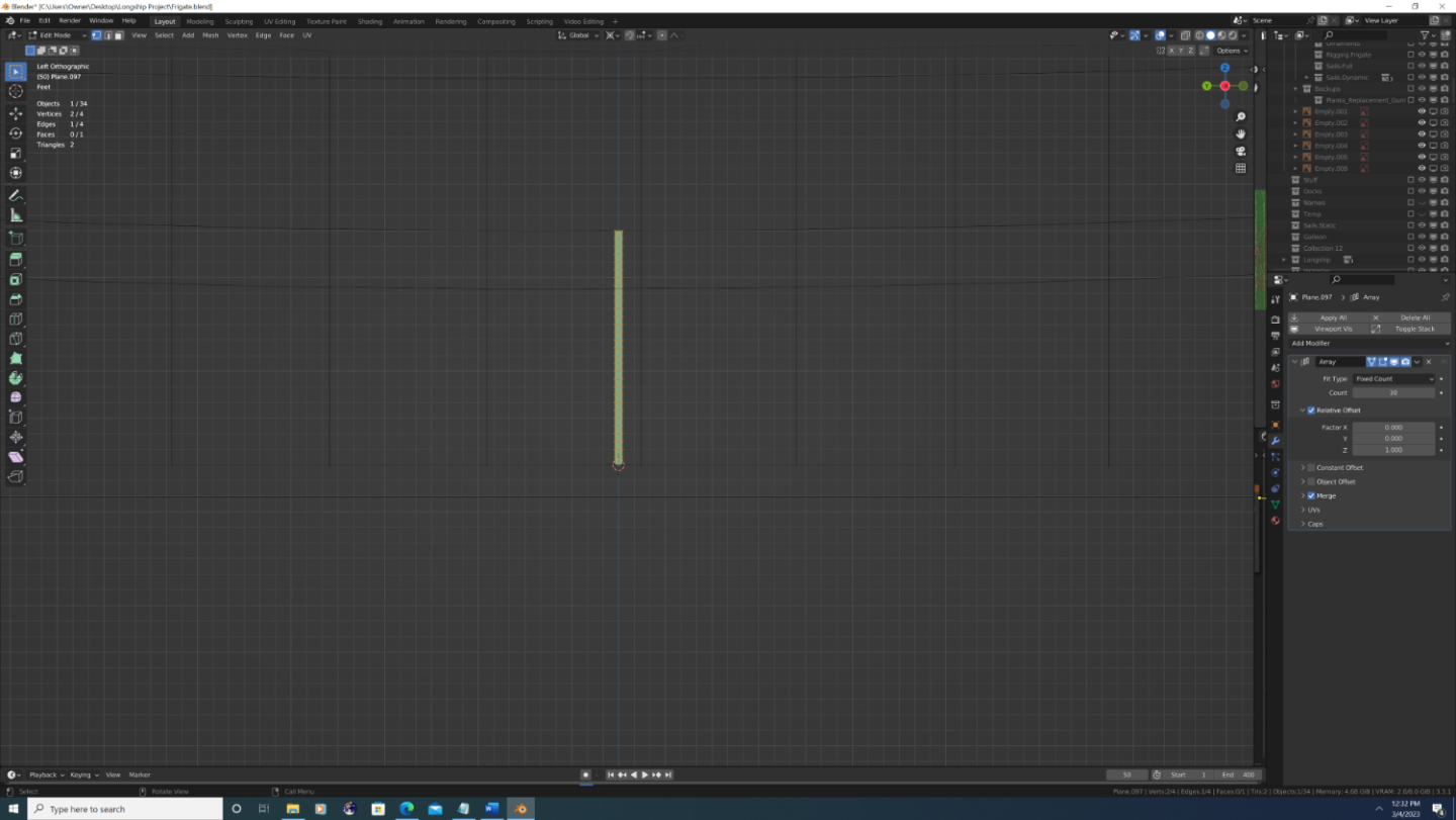
4. Next, I added a curve modifier with the deform axis set to 'z', then I used the eye dropper to choose one of the station line Bezier curves.
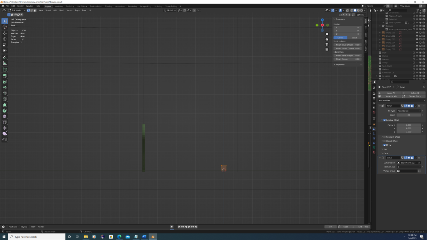
5. Obviously, it doesn't reach anywhere near the lower edge of the main wale so to fix this I went into edit mode and grabbed the top two verties and moved them upwards until the result reached the appropriate height.

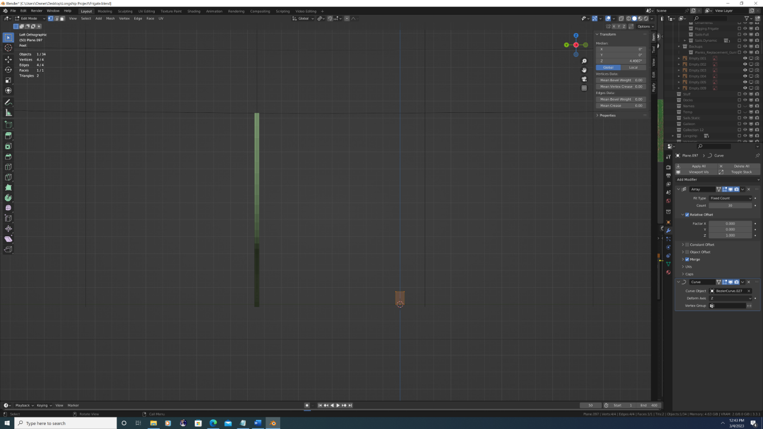
6. When done with that segment, I simply duplicated the plane and changed the 'curve object' in the curve modifier to be the next station line. Each time I would then go back into edit mode on the new plane and readjust the height of the top edge so that the top of the 30th plane would touch the bottom of the main wale. When done, it looks like this:

-
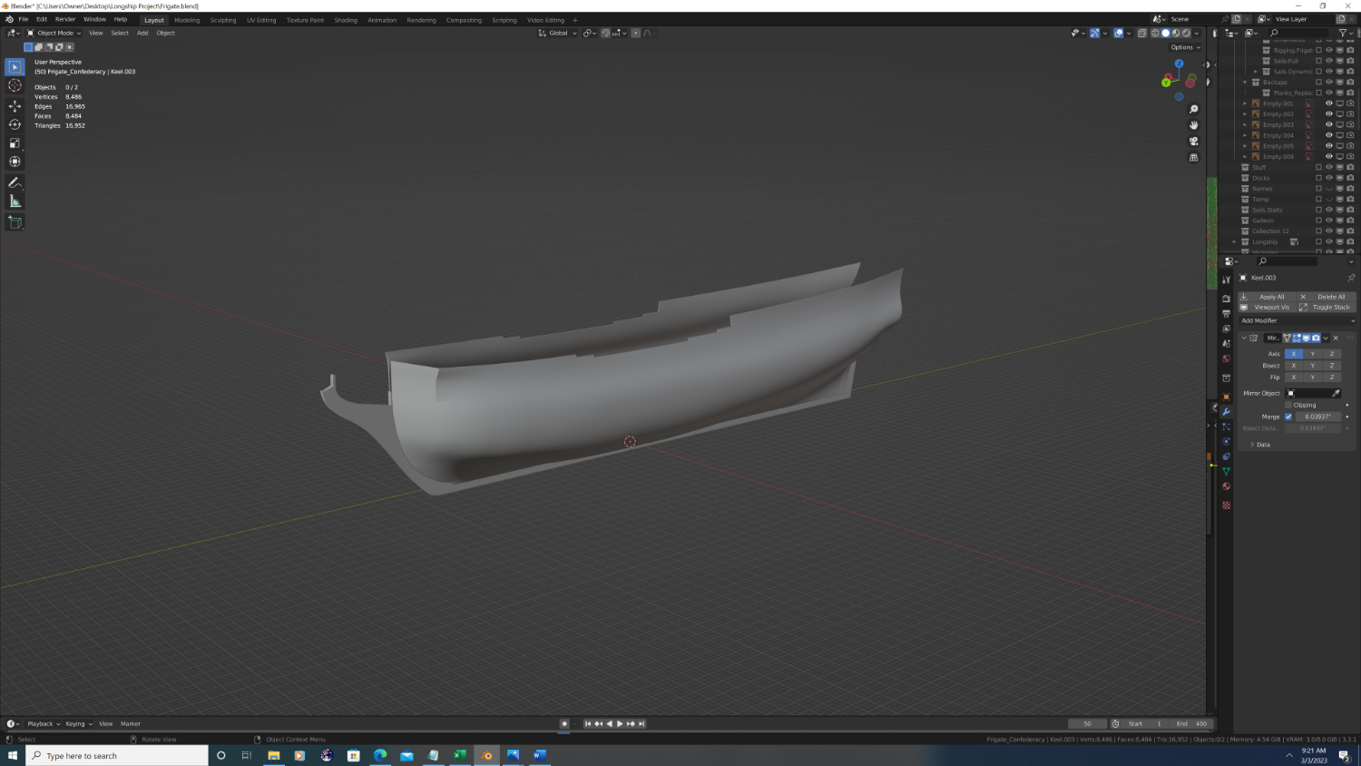
STEP #2 Form the shape of the hull
Put simply, in this step we will create a continuous, flat (palinar) mesh that forms the shape of the hull. This is both my favorite and least favorite part of any build. If done right it will yield stunning results, and make the planking process a hell of a lot easier down the road. If done wrong, it will lead to major shading issues that appear as 'dents' in the hull or it can lead to insurmountable topology problems, such as I experienced with rose.
So as not to seem arrogant let me say up front that I have never gotten it right. That said, this is where I have a new approach I want to try out:
I want to have the mesh not only conform to the shape of the hull, but to also have the topology so each strake can be easily modelled. On a real ship, as the strakes curve around the hull they are wider in some spots, narrower in others, and are even cut as diagonal scarfs in some areas. Put another way, what we really need to care about is the latitudinal 'arc' at key points like the main wale, gunwale, channel strake and any cap rails at different levels (ie. the forecastle, quarter deck).
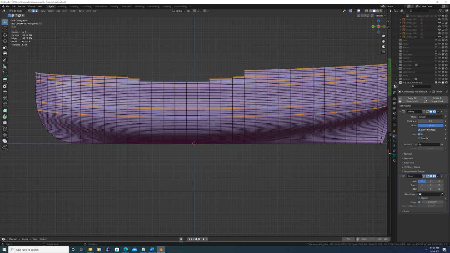
Note that as I cut away the extra geometry, it still extends beyond the plans in some spots, and that's okay for now: strakes that are too long can be fixed, strakes that are too short cannot be fixed.
So that's the goal, but how do we get there from our Bezier curves in step #1...?
-
Okay, here we go...
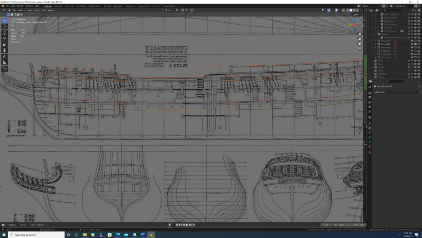
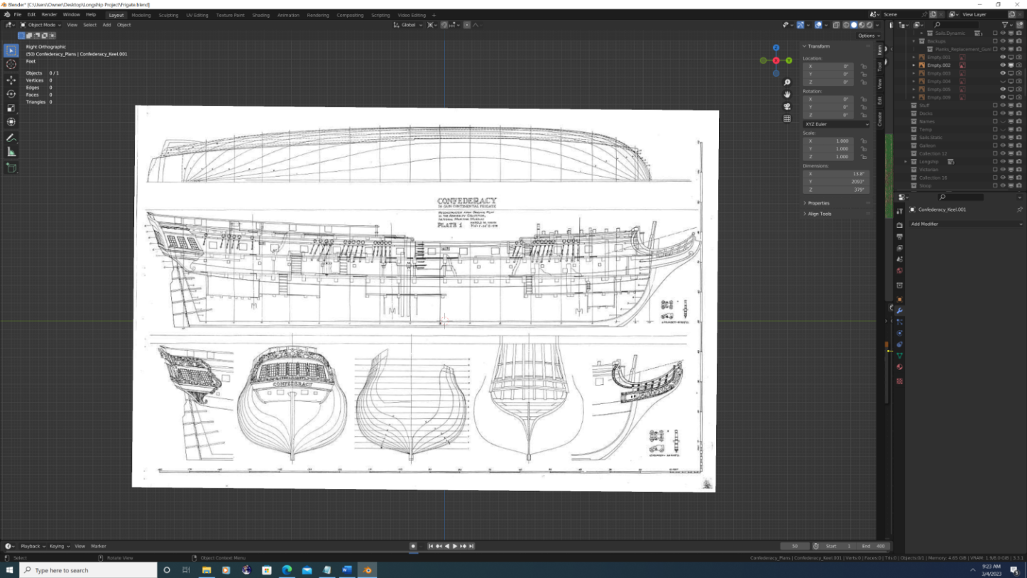
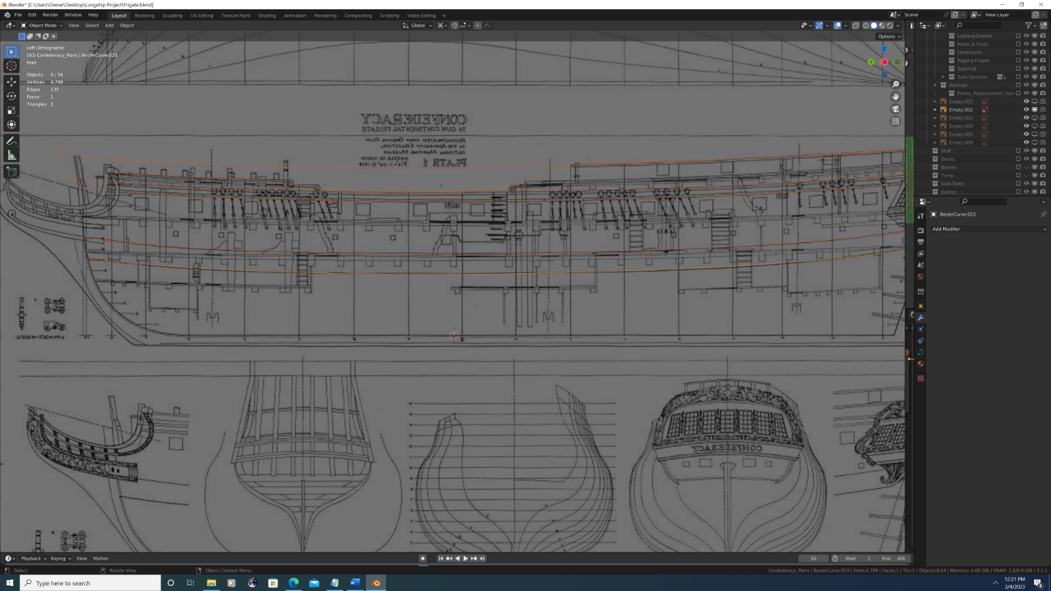
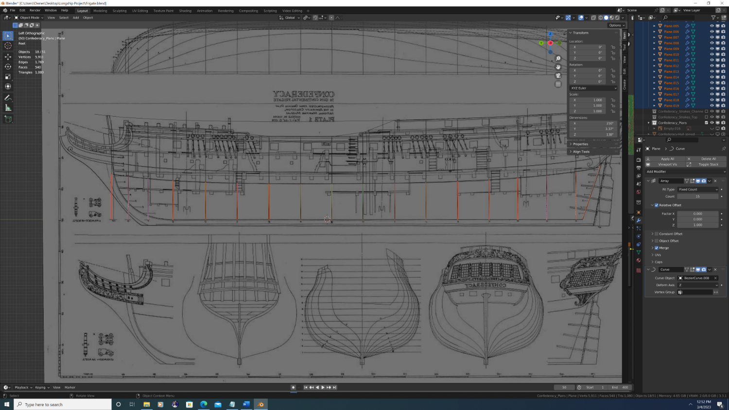
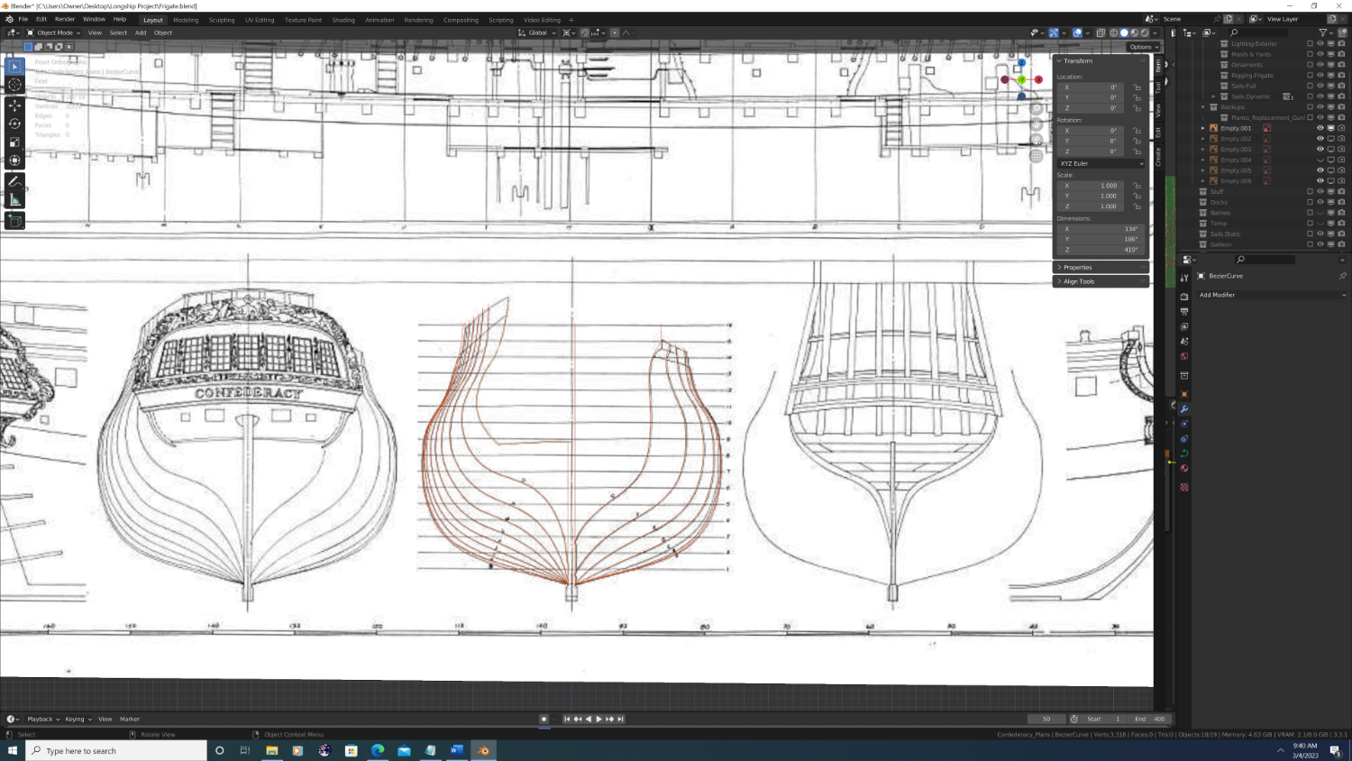
So, the obvious first step was to identify suitable plans. I first greedily gathered up everything I could find on Confederacy, good, bad, or ugly. Then I began the arduous process of sifting through them piece by piece. I ultimately decided upon Harold M. Mann's reconstructed admiralty plates circa 1979 for the National Maritime Museum. His plates are not completely without distortion, but it's minimal, and most importantly, they are complementary to one another.
So I imported them, used blender skew and rotate them ever so slightly (so the parallel lines are in fact parallel), then finally I scaled them.
Then I aligned each plan in the set with the appropriate axis from which I'd be working on them.
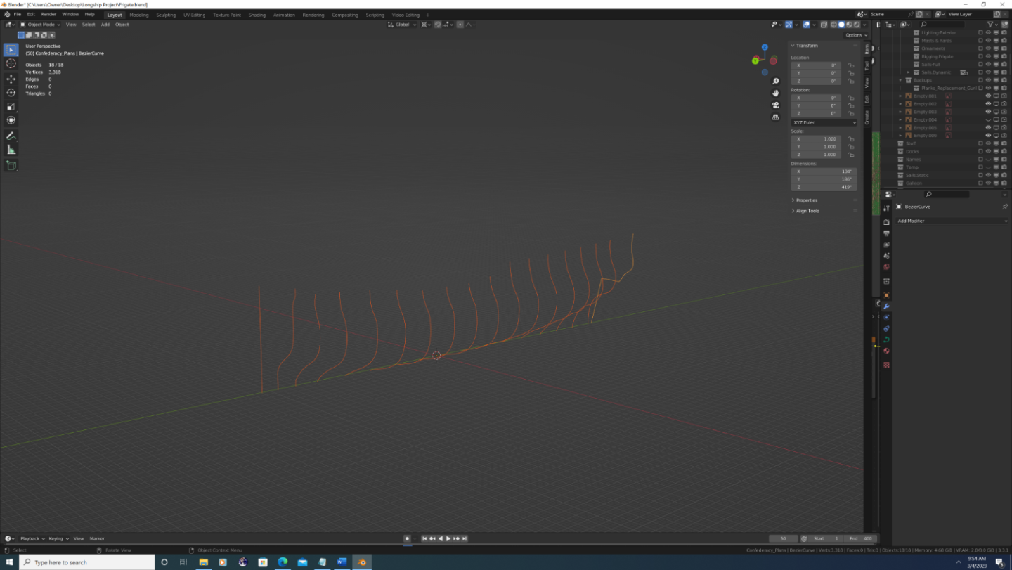
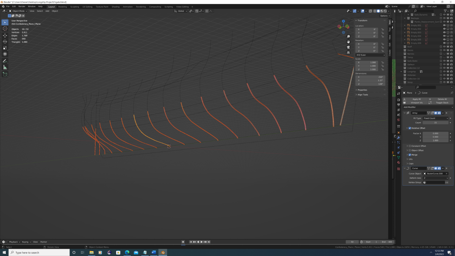
Next, I drew out the station lines.
I flipped/mirrored the bow station lines to the same side as the others, then positioned each one front to back using the half-breadth plan.
Then I used the aft most station line to shape the edge of the planking as it would appear inside of the transom and quarter gallery.
-
Hey Folks, I am both honored and humbled to announce my next Blender build:
USF Confederacy is my 4th ship in Blender, yet will be my first attempt at a full historical recreation. While ‘Rose’ will always be my first love, I plan on taking many lessons-learned from my little-brig-that-could and apply them to a project on a grander scale.
Goals of USF Confederacy Build:
Accurate
With Rose, I proved to myself that it is possible to do comprehensive rigging and sails on a 3D model. I had seen some absolutely stunning 3D builds on MSW before I joined, but I noticed that 99.9% of the threads stop during the rigging process (I’m talking about full digital builds; not those done to 3d print parts later). Why did so much excellent work not get completed? Well, because in the 3D world rigging is actually where the overwhelming majority of the work takes place. I hoped to be among the first, because visually, it’s the yards, spars, sails and rigging that occupy the majority of the space taken up by any model ship.
Anyway, with Confederacy I want to bring the same level of realism to the keel, frames, planking, carvings and fittings – and have it be historically accurate this time. Thus, any deviation or parts taken from the designs of other ships is to be well planned out and documented up front.
Light
Rose clocks in at 6.2 million vertices and requires 14Gb of RAM and 7.5Gb of VRAM to render… without water, clouds, or anything else in the scene. Even if I never sell or distribute her (I’m not in this for the money lol) I do plan on one day doing renders of Rose duking it out with other ships in an epic naval battle, or perhaps sailing up the Thames in Victorian London. Ergo, I must do more with way, way less.
I’ve long been imagining/theorizing techniques to reduce geometry/improve performance and I am genuinely excited to try them out.
Beautiful
Photoreal or bust, ‘nuff said.
Excited to share – will post steps from the planning phase later today.

Best,
-Nate
- CDR_Ret, oakheart, wernerweiss and 2 others
-
 5
5
-
Hey Everyone,
I know I'm long overdue for an update post on Rose, so here it is...
List of changes:
1. Mounting brackets securing the dolphin striker to the main bowsprit cap have been added
2. Dolphin striker color changed to black
3. Leading edge of the cutwater has been subtlety beveled from Gripe to tip of the bobstay piece, then inboard to the gammoning knee
.thumb.png.1482a58547e84012969dda37c3113bbc.png)
4. Double jeer blocks added and cathead rigging completed portraying the anchors in a stowed position resting atop the fore cap rails
.thumb.png.3f12b9c8b43222613be1e6ecd4723a1d.png)
5. Twin 18-pound bow chasers placed on the gun deck
.thumb.png.d854c4fb29d0e0f4834acdc8c08771b1.png)
6. Fore Topgallant bowlines added
7. Buntlines added to the Fore topsail and belayed to the 4th & 5th pins on the fore companion’s pinrails
.thumb.png.ed2b94d8ae91295b869a642157196ce9.png)
8. Tacklines have been added and belayed to the bumpkins and to thimbles above the main wale for the fore and main course sails, respectively
9. Fender blocks added to the outer hull
.thumb.png.1043612ad3fd9db0e791cd87d2ccdec5.png)
10. Grates on the main deck redone from scratch, including screws
.thumb.png.7d516a7b33e7a380df112982eb0e507f.png)
That's all for now - feedback always welcome!
-
-
Hey Folks,
So I was wondering if someone can help educate me on how sails come to be neatly furled atop the yard, given that:
1. The Buntline blocks rest in front of the yards and the Buntlines themselves fall in front of the sail to where they are tied at the foot of the sail.
2. The Clewline and Clewline block rest behind the yard.
Basically, the Buntlines and Clewlines seem to want to fold the sail in opposite directions, which to me seems very non-conducive to a clean fold/roll of the sail cloth... What am I missing?
Thx in advance,
-Nate
PS - please ignore the problem with the stirrup/horse protruding through the sail (I have yet to fix this)
Figure 1. Buntlines

Figure 2. Clewlines (and tackline at the sheet block)
-
Hey Allan,
Sounds like you already got a number of volunteers, but I'm happy to offer my services as well. Just let me know if I can be of assistance.
-Nate

- Montaigne, allanyed, thibaultron and 1 other
-
4
-
FYI, on a ship this size, there there would also be a third post between the mast cap and the futtock on each platform (see below).
-
Looking good Kurtis! A couple minor notes:
1. Your deadeyes are spaced too far apart... To climb the shroud, the crew must be able to step from the deck or rail onto the lowest ratline (or spacing block), and logically, these have to be above the upper deadeye in each set.
2. It looks like you wrapped each shroud around the masthead above the futtock in the correct order (well done!). However, from here it looks like the mast head remains cylindrical instead of squaring out... It should look like this:
.png.8b9c24b0deee787ec7a8c67583cf7f24.png)
3. Finally, if there's any rearward lean/tilt to the masts, the futtock and cross-trees should be angled forward (to provide a flat perch), but the mast cap remains100% perpendicular to the lean of the mast. I did this wrong on mine and it later caused lots of problems with the rigging. Not saying you did this part incorrectly, just a lesson learned from my project.
Keep up the good work,
-Nate
-
-
Hey folks, so I was wondering if anyone can help me identify the name of this particular line (see screenshot). It's part of the 'gear' on the course sails, and opposes the clueline along with the sheet, except it pulls the sail down and forward - so in conjunction with the sheet - the sail is pulled straight downward.
I apologize in advance if I missed it elsewhere in the forum, but without the name, I had not much hope in searching for it.
(BTW, is it spelled 'Clueline' or 'Clewline'? I've seen it both ways...)
Thanks in advance.
-
-
Hey Folks,
So I'm almost done with the boats and I'm starting to play around with their general position in relation to the brig.
Feedback welcome here:
The 31 foot-long boats are rather oversized for this Brig. Thus, they don't fit cleanly behind the aft channels. I'm not willing to redo the boats at the moment - I will eventually do several Launches, Pinnaces, etc. and will swap them out when I do - so in the meantime I have to decide whether to place the davit cranes behind the channels, between the spacing of the main shroud lines (extending beyond the channels), or affix rails atop the main deck... which would mean only one boat unless stacked like Russian nesting dolls...
Any thoughts?
.png.40fbe7c6c3b9c731a09f5afd5fb55a47.png)
.png.eb080f3cb11a3c76a3dfcf75268bafc1.png)
-
Thanks guys.
A couple minor updates in the meantime:
1. Knight's heads started (need to finish the caps, and reposition a couple lines of rigging). They are spaced a bit wide, but that's intentional because I'm modelling them after the style that has a stock that slides in from the top and locks the bowspirt in place.

2. Spanker Boom holster is now modelled and in place along the taff rail. Not sure why they opted to go for a double-knocked holster, but I did it precisely per the plans.
3. I smoothed out the planking near the stern where it curves the most.
.png.64d013b204fe83a63ad96176b0dc73e5.png)
- mtaylor, oakheart and whitejamest
-
3
-
-
-
4 hours ago, Martes said:
Another thing is that the ports should be able to be closed. I am not sure there were permanent lids fitted (most likely not), but, again, there is a number of situations when you could want them to be shut with something.
Yup, good observation:
I actually did the lids some time ago (see image), but I think that because of the very short distance between the hinges and cap rail, this brig would require the split-style port lids that fold both upward and downward. I was holding off from further work on them until I confirm the appropriate style.
Best,
-Nate
.png.0e94ecab1f513afa4ecd92dcb6f0bdbb.png)
-
@Martes - So I checked the height of the deck, and I think it's fine. I think it may have been an optical illusion caused by the outward tilt of the stern paneling plus the fact that Carronnades sit lower than even small cannons. The image below shows a mid-sized gun (9-12 pounder based upon the bore size, carriage is the same either way) positioned as a rear chase cannon.
Based upon @mtaylor's comment - I doubt whether this brig would even allow rear guns unless they were permanently fixed behind the tiller rigging, which seems unlikely. The plans also show something along the bottom edge of the stern ports, which I now believe to be mooring chocks.
Anyway, based upon this info, what's your read on the deck? You think we can we call it close enough?

-
54 minutes ago, Martes said:
Then, try to get rid of the enormous amount of redundant vertices in 2, 3, 5 and 6 - such regions usually cause terrible headache for smoothing algorithms.
Martes makes a good point here - To clarify my post, this is precisely why you'll need the 'only smooth' option checked. Even then it's a gamble. Question: is the geometry connected? Full quad topology on the lower planking?
If not, it may force your hand on sculpting.
-
First off, the hull is not bad as is, but yes, there are a few anomalies that can probably be fixed. To my eyes, you actually have dents more than bulges, but the fix I propose is the same either way. A couple more slightly more feasible alternatives than redoing the hull:
1. Use a 'Smooth corrective' modifier with 'Pin Boundaries' and 'Only Smooth' selected, placed higher up in the stack (above any sub-surf unless you're willing/able to apply the SS first).
OR
2. Light sculpting, specifically the fill tool (low strength, broad radius, top-to-bottom strokes), followed by the smooth tool. General philosophy here would be expand areas first, then subtract.
Again - the model still looks good in current form, so it'll be up to you to decide if the juice is worth the squeeze.
-Nate
-
Just a quick render for fun before I start working on 'Rose' this evening
.png.980e21e005ce8023e5ecff3271838535.png)
-
@Ab Hoving Thank you very much!
-
Looking great Kurtis!
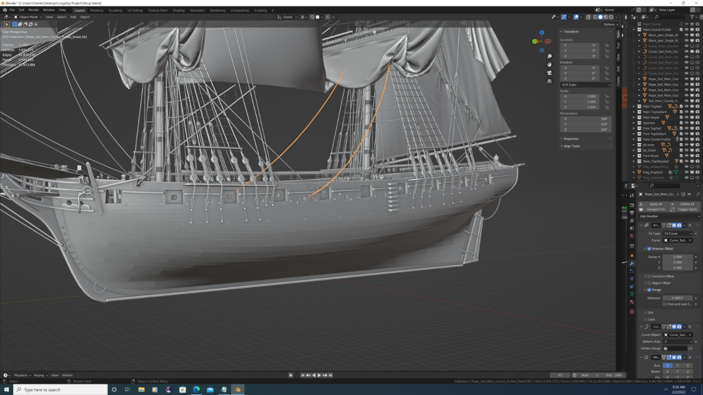
Not sure how you plan on doing the rigging, but as a comparative performance estimate: My brig is around 1.35Mil vertices with no rigging and 5.98mil vertices with. That said I did a few 'uber high poly' lines where I thought I may want to do closeup renders later, but even without those, I'd estimate that the total count with rigging to be about 4.25mil (currently I'm about 80% done with rigging), or about 75% of the actual mesh when all is said and done. I'm using 10-sided cylinders as in the base rope segment. If you can back that down to octagons, you'll shave 20% off the top + an exponential factor (my math is good, but not that good) when you merge duplicates caused by the segment arrays.
Whatever you decide, keep up the good work!
-Nate


.png.ec5dda53dfb7de6b3464cb5411240224.png)
.png.d4493b50d88f40e79a511a6de48e20e4.png)
.png.23bea674f436d0d8f6ca6dce527a5874.png)
.png.f12bde3d17e7b3fc078dda4c1a57e331.png)
.png.ad3860bc12a92828ea969553951473ff.png)
.png.8e2fd99b22af4c8fd9e9bbebbca8663e.png)


.png.22e820814075fd98fd1d9a7d481332d0.png)
USF Confederacy in 3D | Blender
in CAD and 3D Modelling/Drafting Plans with Software
Posted
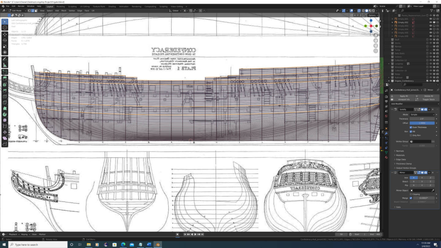
Step#2 (Continued again...)
Before we can join these together, we need to repeate the process for the upper segments.
My segments are as follows
a. The top of the rabbet (which also the origin of the overall ship , same as it is on plans) to the bottom of main wale (already covered in last post)
b. The main wale
c. The top of the main wale to the bottom of the channel stringer. FYI - I'm calling this the 'gun wale segment' because within this area runs a gunwale stringer, though interestingly, it neither follows, nor influences, the overall run of the strakes (more research req'd)
d. Bottom of the channel strake to the top of the lowest cap rail (forgive me, I don't know the proper name for this piece if there is one)
e. The top segment, which is actually multiple segments, but luckily the change in the arc along between the curves is minimal - so I was able to do it as one piece.
The 'yucky' part is that on ever level above the first one, we need to also align the 'floor' of each plane before we scale it vertically. This, sadly, doubles the workload on each one...
The next level up would be the main wale. Now, the models I've seen depict two heavy duty stringers along the top and bottom edges, and the planking in the middle is cut into a series of scarfs, lap-joints, and other assorted jigsaw pieces lol. However, the total width appears to be around 5 strakes, so that's what value I used.
If you're interested in following along the steps are:
1. duplicate the plane array from the lower segment along the same station line
2. change the array modifier to the number of strakes in the new segment (5 in this case)
3. In object mode, press 'g' to grab the whole thing, then 'z' to move it upward to align the bottom of the new array with the top of the array segment below it.
4. Go into edit mode and move the top edge up or down so the highest strake aligns with the next curve up (same as we did for the previous section)
After the main wale was done it was simply wash, rinse, repeat until all station line curves within each hull segment had an array of planes on it.
And, thankfully, I was finally ready to join the hull into a single object...