HOLIDAY DONATION DRIVE - SUPPORT MSW - DO YOUR PART TO KEEP THIS GREAT FORUM GOING!
×


turangi
-
Posts
276 -
Joined
-
Last visited
Content Type
Profiles
Forums
Gallery
Events
Everything posted by turangi
-
Very nice! I'll bet you learned a lot.
-
 I normally seal the wood with a dilute oi based varnish or shellac then sand smooth. It prevents raised grain especially if you are finishing using water based paint or water based clear finish.
 -
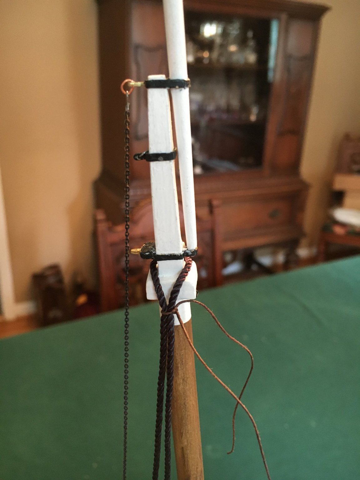
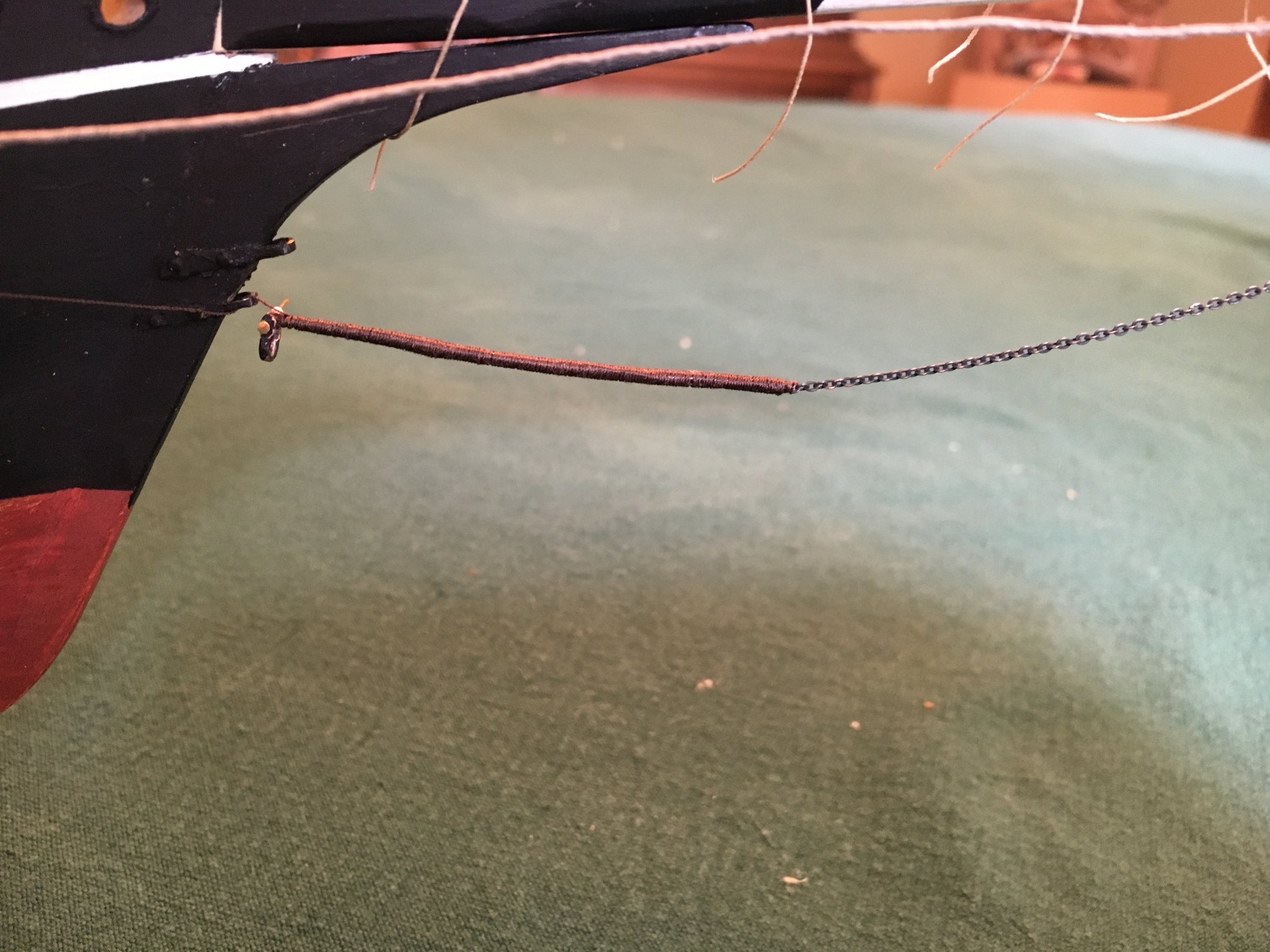
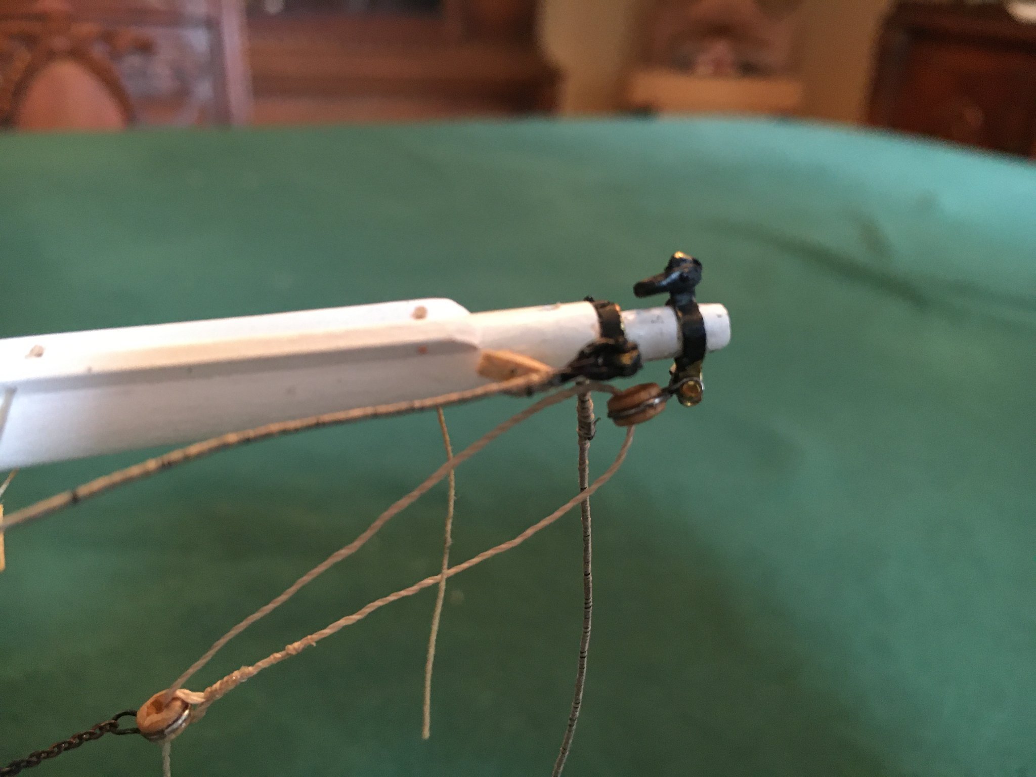
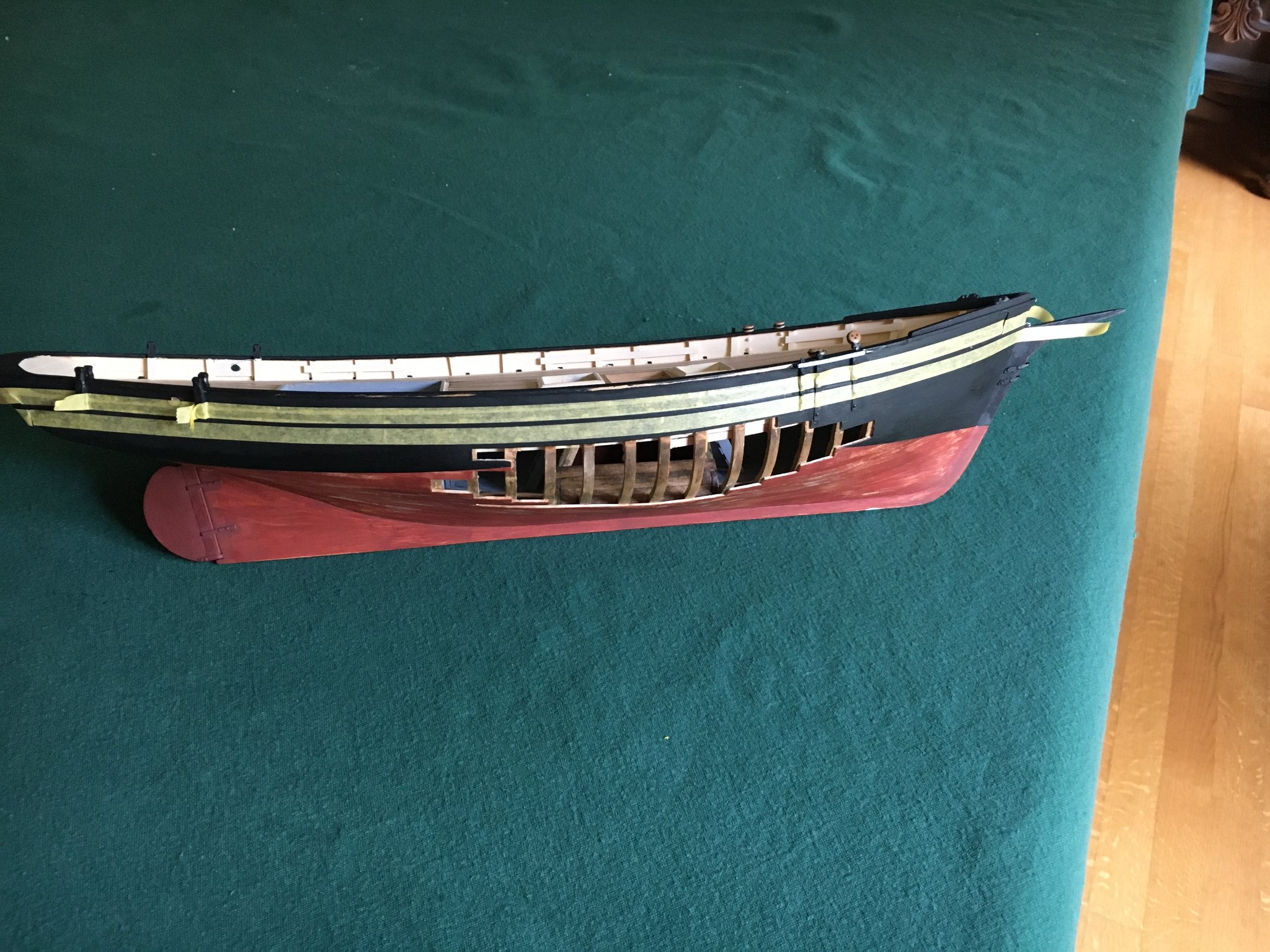
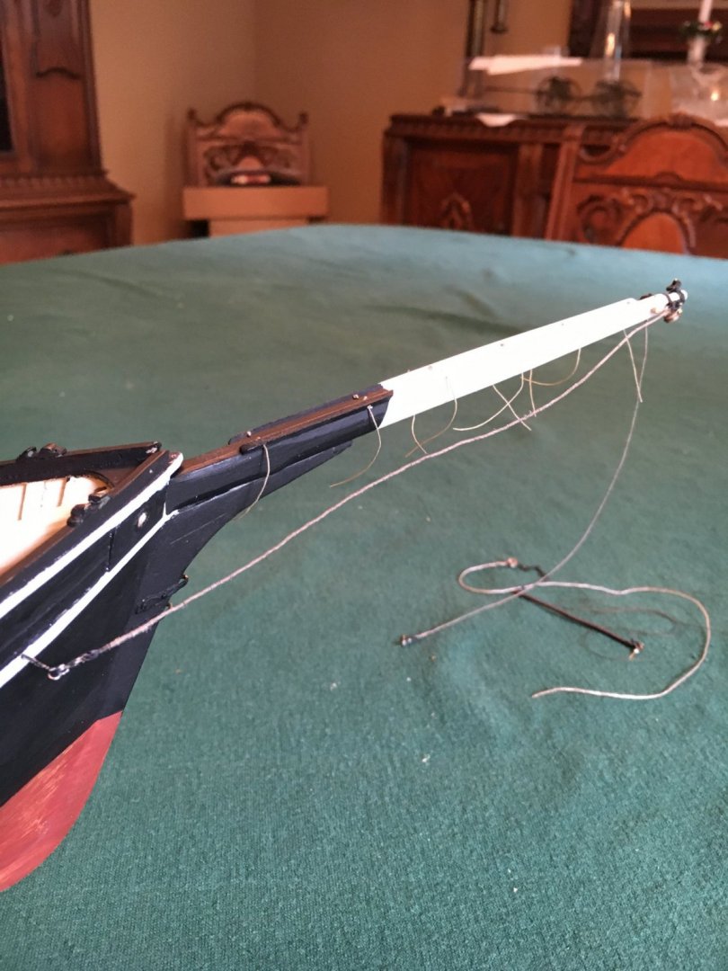
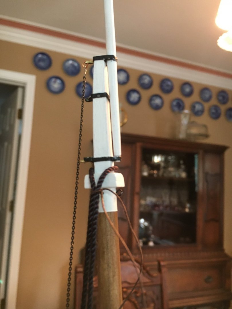
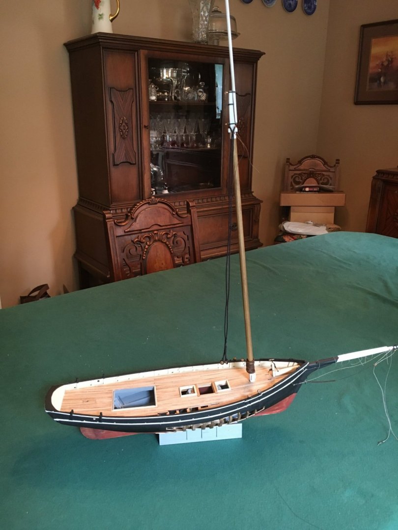
Time for a bit of an update. I have been working on the various rigging points, lines etc.. Neither the mast or bowsprit are permanently attached yet but fitted for a trial run. I thought it best to complete as much of the rigging work as possible beforehand as it is easier off boat. I had read of the difficulty of serving the chain going to the bowsprit and use of shrink tubing or other methods so I tried a different approach and applied 5 minute epoxy to the appropriate area of the chain to achieve a smooth surface, let it harden and then served it, worked to my satisfaction. The shrouds were a challenge as they called for serving full length, I gave it a go with little success so decided to just leave them bare which I am sure I will regret. The plans called for some small bullseyes for the bowsprit chain assembly and said to just drill out the center of a deadeye to create a single hole, no go. What I did was carve out the center between the hole with a scalpel to create a divot and then drilled them out, worked a champ. My next step will be to build a stable base for the model and proceed with the permanent rigging A few lousy pictures:


-
Excellent, looks very nice!
-
Your model is looking wonderful! Have you considered leaving part of the cabin roof off in order to see the interior details?
-
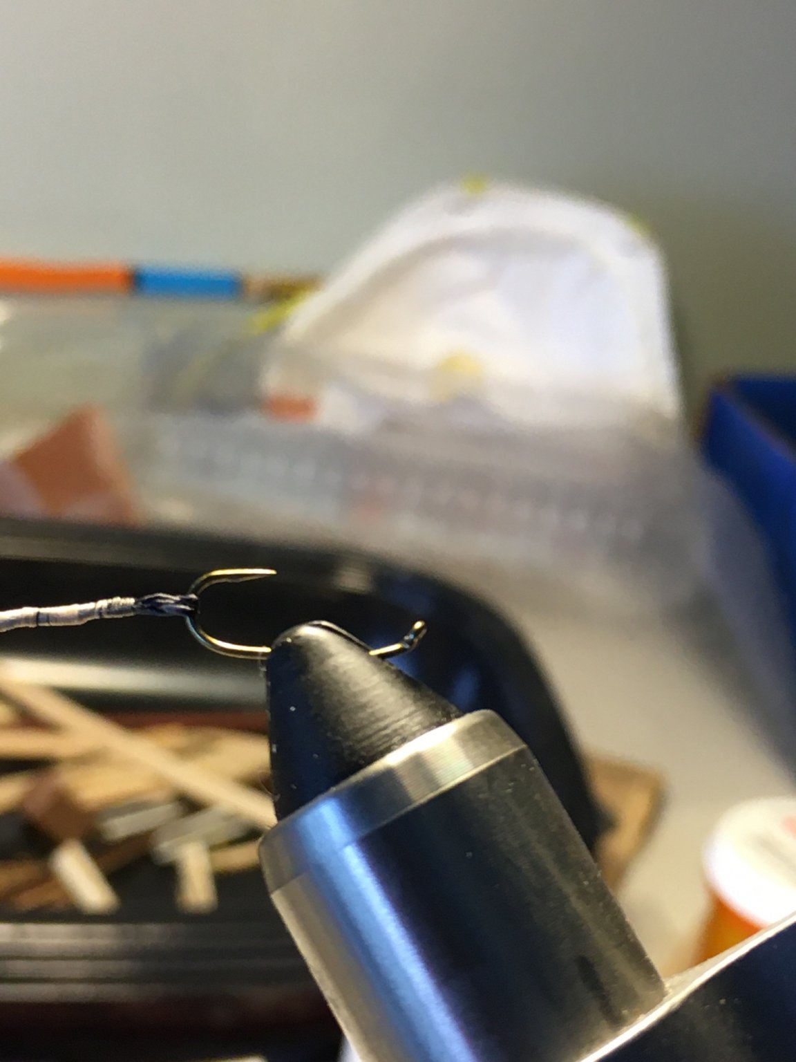
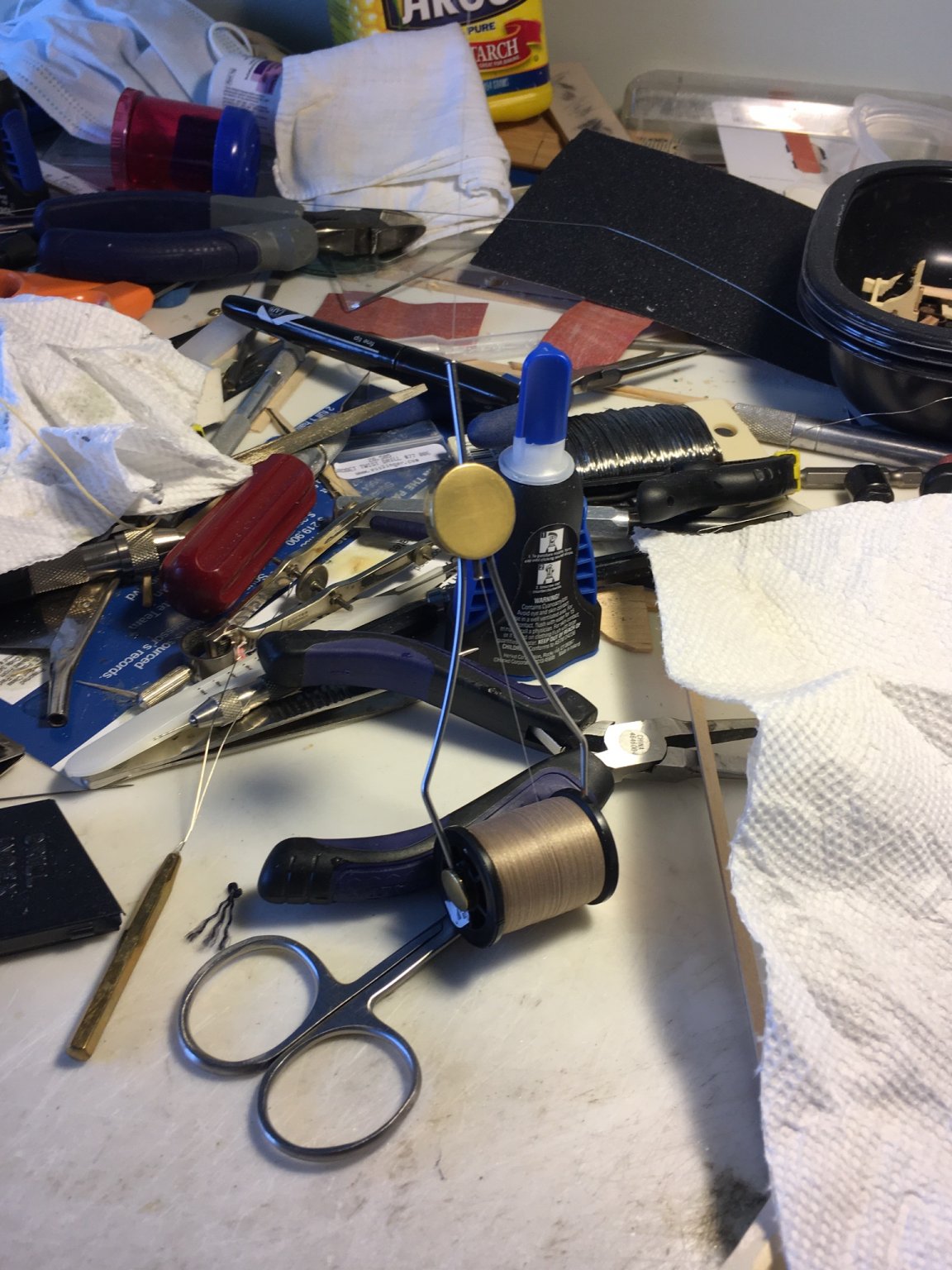
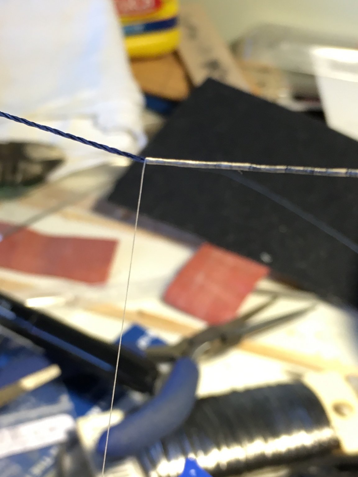
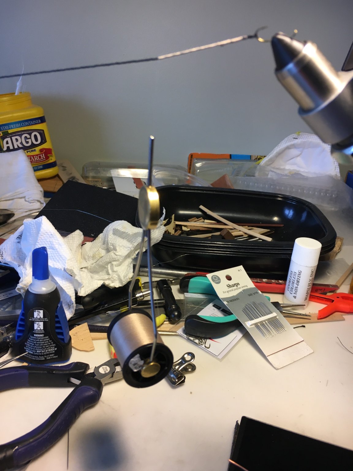
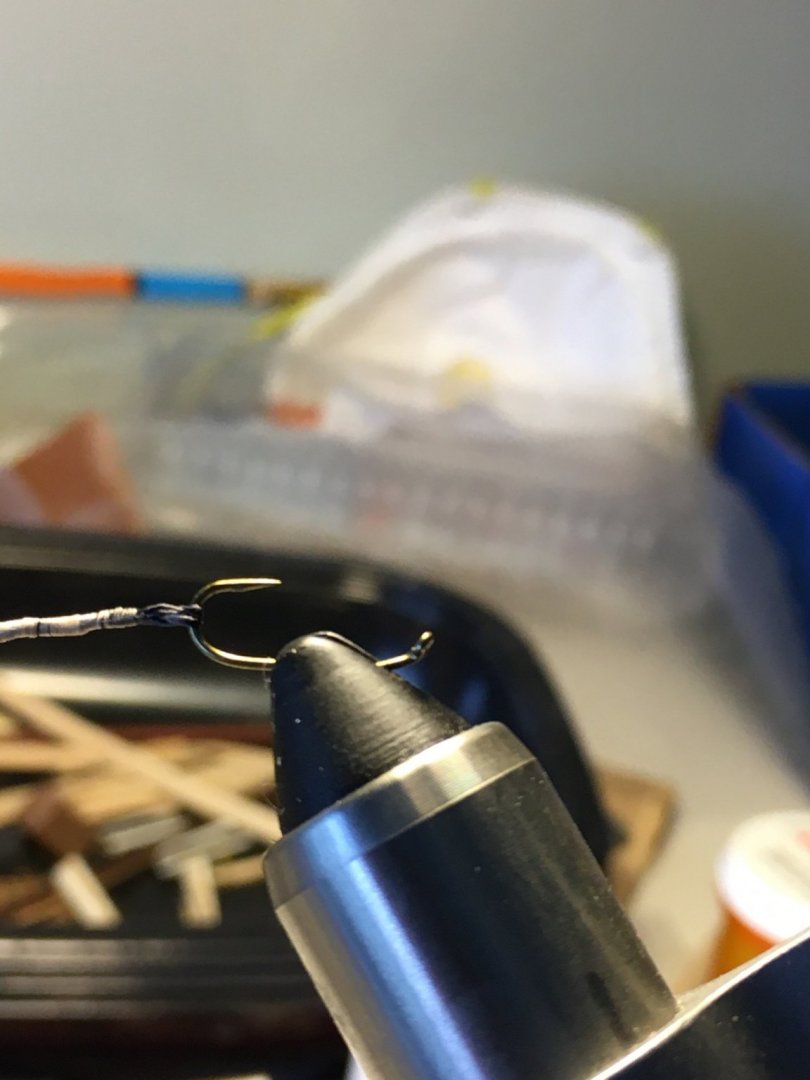
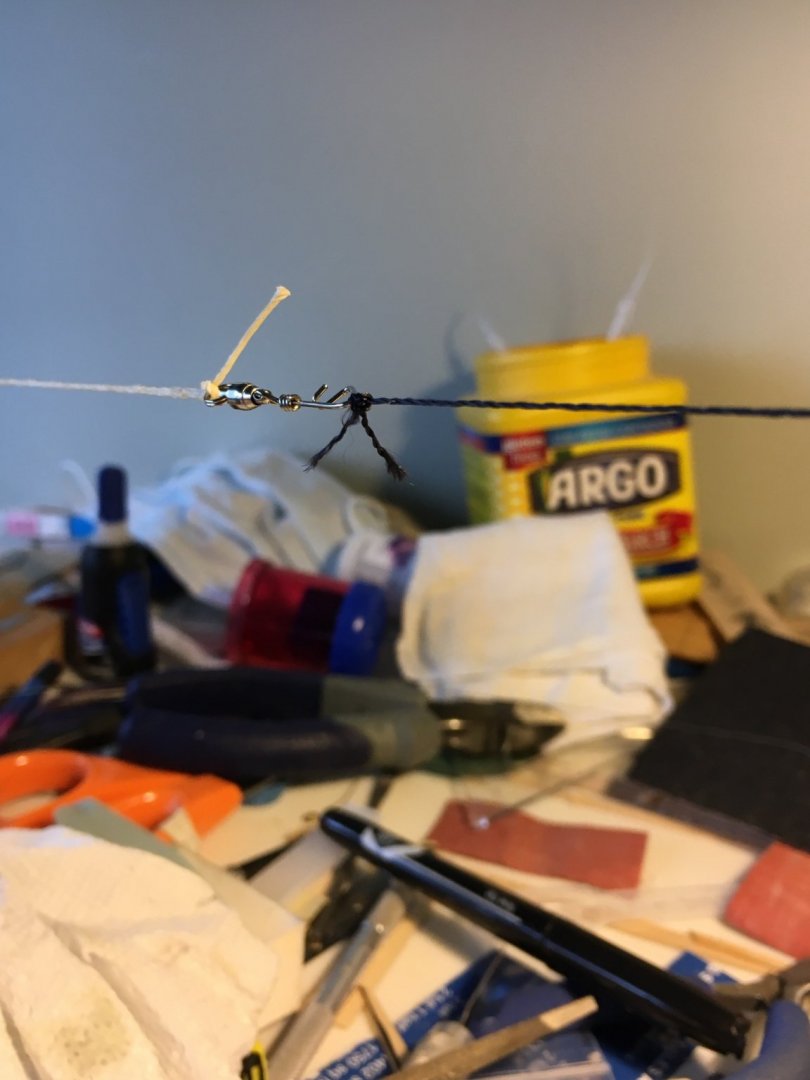
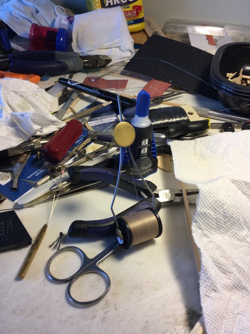
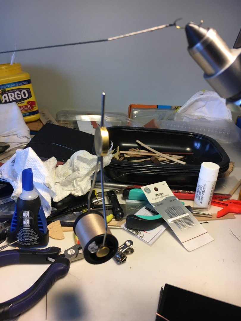
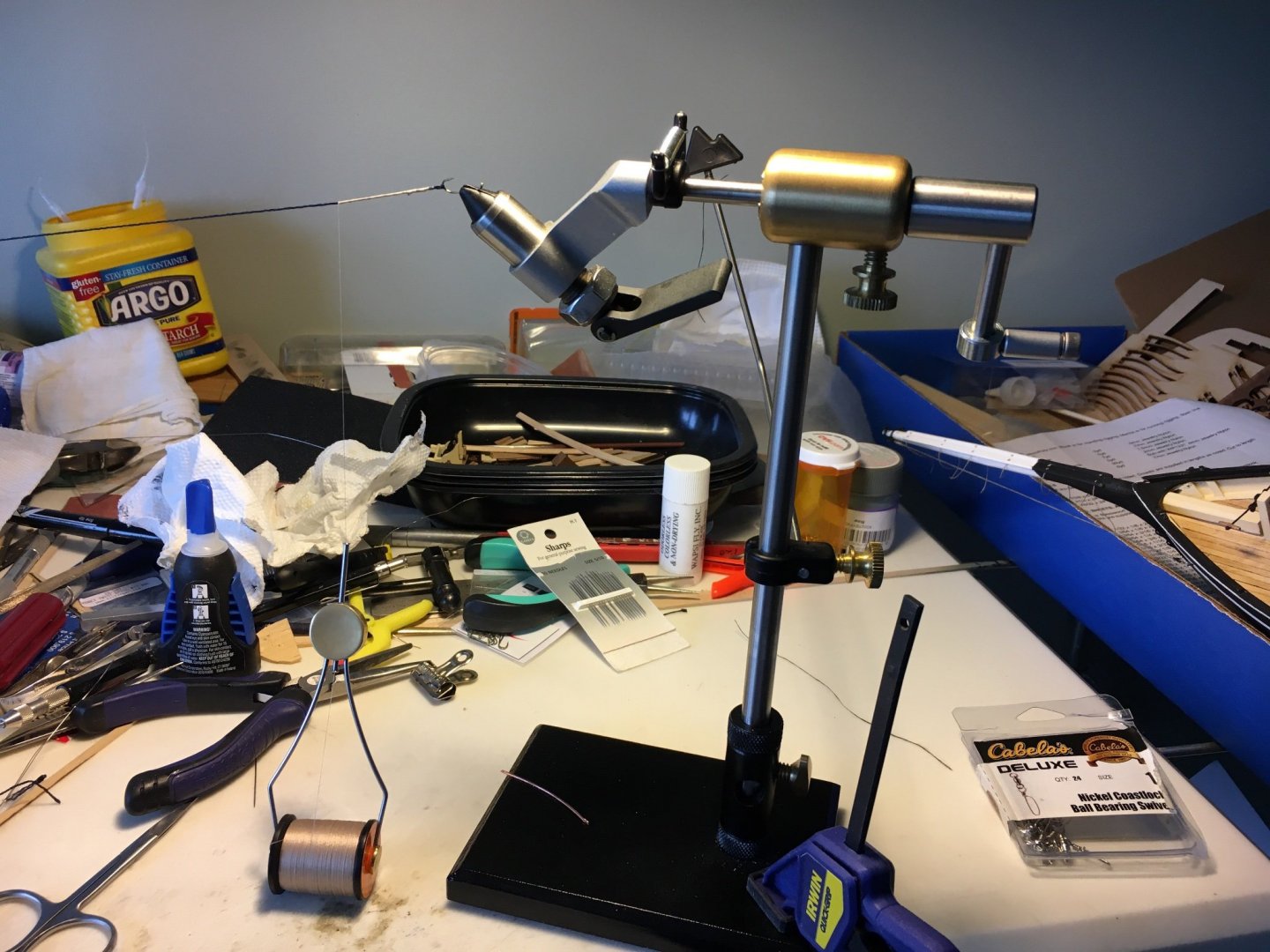
As promised my cobbled together apparatus for creating fully served lines called for in the plans. My first lesson is that I need to clean my workspace, ignore the clutter. I first inserted a barbless fly hook in my rotary fly tying vice. I next spliced the line around the hook, much easier if you dip the end in thin CA glue to create a rigid portion to pass through the running line. After creating the splice I thread the serving material on a fine needle and pass it through the splice a couple of times to hold it together. Next I secure the other end to a swivel to allow the line to rotate. The serving thread is in my fly tying bobbin the whole time. I rotate the head of the vice while holding the tag end of the serving thread along the line several turns to lock it tight and then apply a touch of CA to secure it. I then just continue to turn the line with the rotary vice using the bobbin to feed the serving thread. I also apply diluted PVA glue to the served area as I complete several inches and then keep serving. As I approach the required length I leave enough of the line to pass through the fitting on the bowsprit, disconnect the line from the apparatus, pass it through the fitting, make a splice and serve that area and finish with some half-hitches, a touch of CA and the diluted PVA. Rather like tying fishing flies. My directions are probably as clear as mud but feel to post any questions or contact me. No patents pending so free feel to copy my cheapskate serving apparatus 😁

-
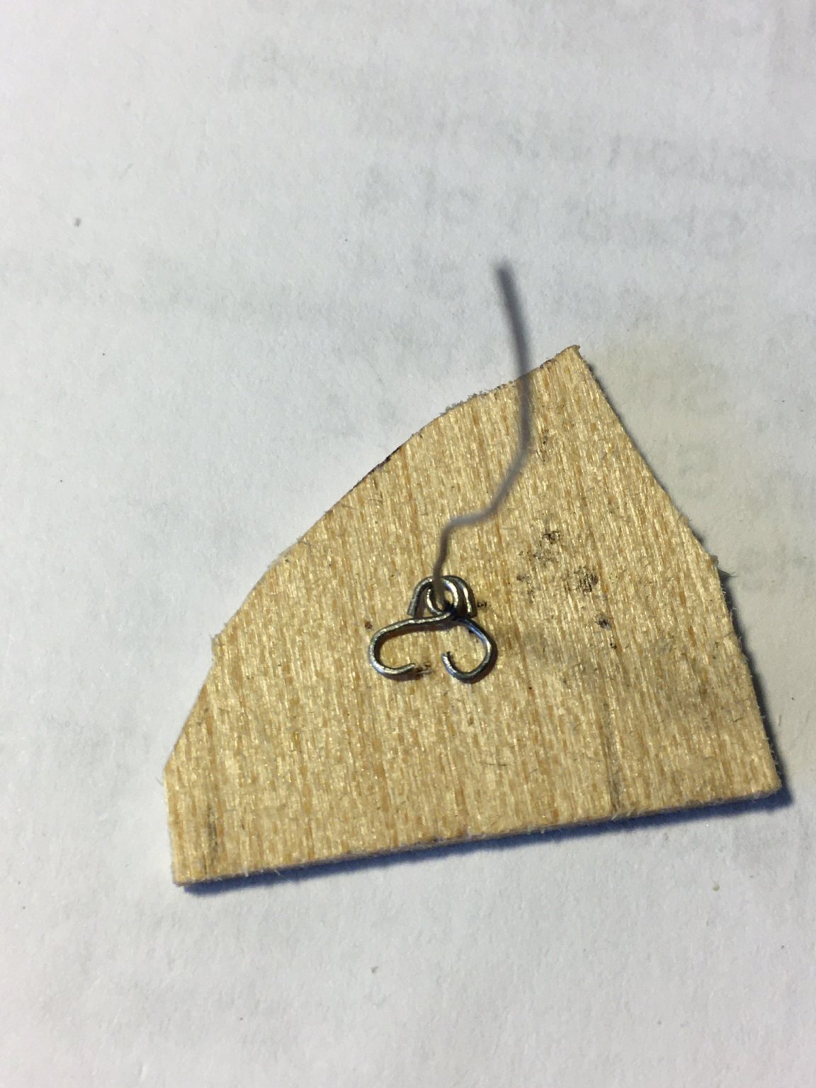
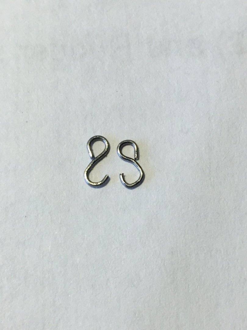
A bit more work, I decided it was time to start rigging the bowsprit. The directions called for sister hooks so after Googling them to see what they were I made up a couple and was fair happy how they turned out. I used a bit of wire and bent it into shape. Not sure they are to scale but will not let anyone near the model with a micrometer. I also served the line full length with a Rube Goldberg contraption I cobbled together and will post photos of that later.

-
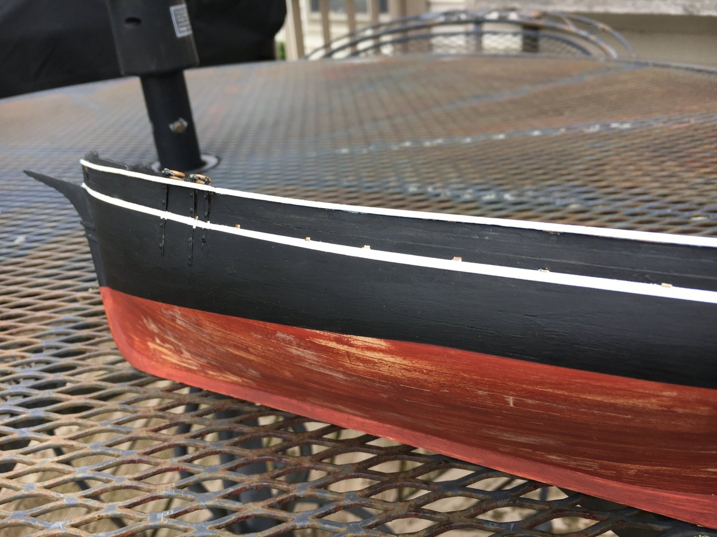
A bit of an update: I moved on to painting the accents on the hull below the scuppers and the edge of the cap rail. Liberal use of masking tape sure helped! After removing the tape I went back and touched up a few areas and finally decided enough is enough already. I have to shift my perspective from a microscopic view to a two foot view, looks good to me. The plans called for a cream color the same as the interior but I exercised artistic license and painted them white for a bit more contrast. I also stained the exposed hull frames a bit as they looked too pristine to me. I needed some eyebolts and after trying to close the gap and solder it on the kit supplied items made my own by twisting wire around an appropriate sized drill bit and like them much better, very easy to do.


-
Looking great and wonderful tips! As a novice myself I am sometimes reluctant to post my methods of work as I assume they are well known but do so anyway as it may help another person like me. I admire your soldering skill, I usually muck it up an end up with a huge blob of solder.
-
Both models look great! It is very interesting to see the different approaches to the same task, always something to learn.
- 101 replies
-
- 1
-

-
- emma c berry
- model shipways
- (and 1 more)
-
Looks good, the knight heads are surprisingly complex to install correctly and you are correct that the cap rail will cover any tiny issues. Coming along great!
- 161 replies
-
- 1
-
-
- Model Shipways
- Emma C Berry
- (and 1 more)
-
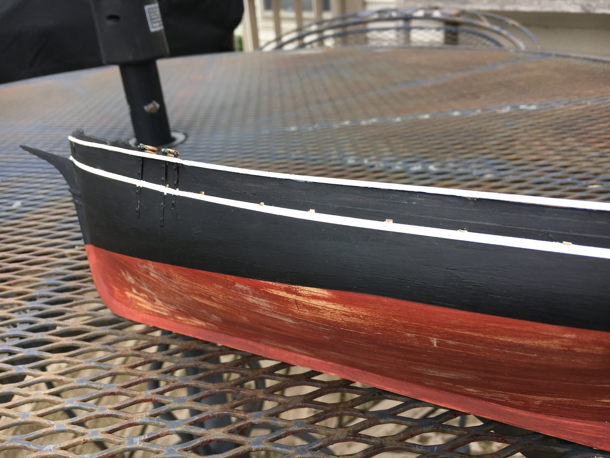
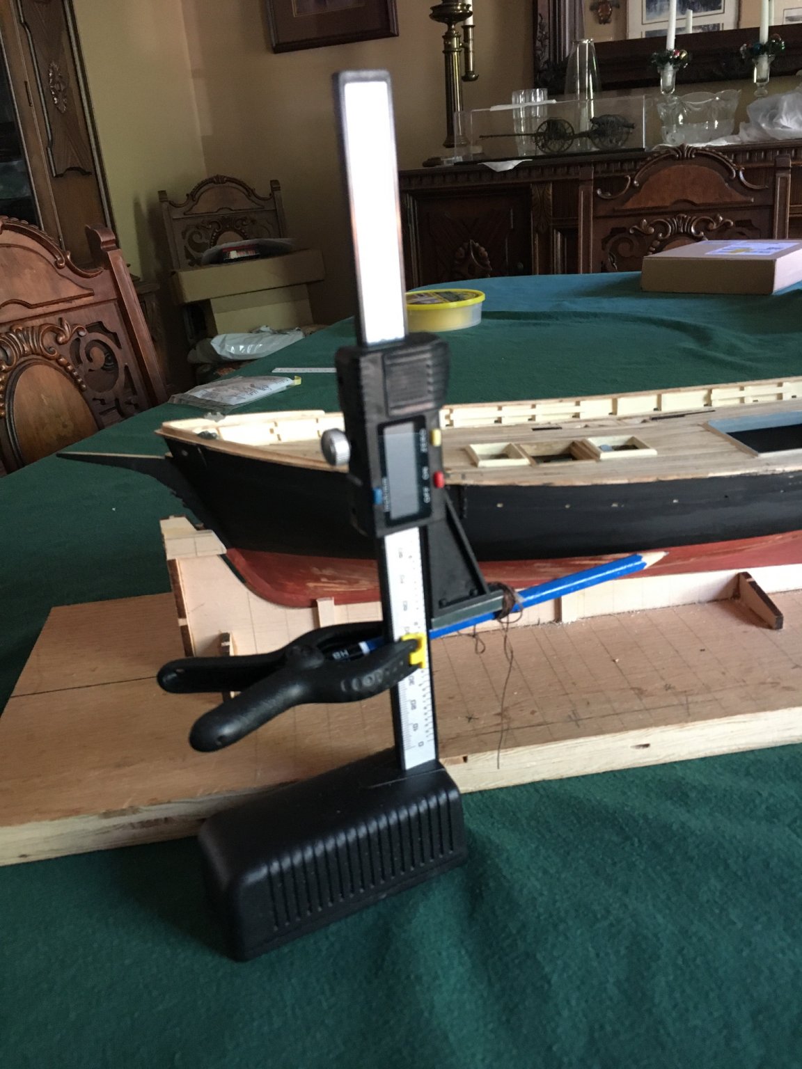
I forged ahead at my usual breakneck speed😉. I fabricated and installed the fittings on the bow, quite straightforward with some file work and bending. I next turned my attention to marking, masking and painting the waterline area using hopefully fairly accurate measurements from the plans. I cobbled together a marking apparatus, then masked the area with 6mm Tamyia tape and dashed on some paint. I am satisfied with the result. I dragged my feet on doing this as it had disaster written all over it in my mind. Went well I think. One side down and hopefully the other tomorrow.


-
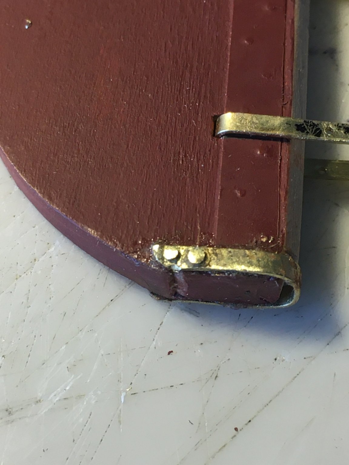
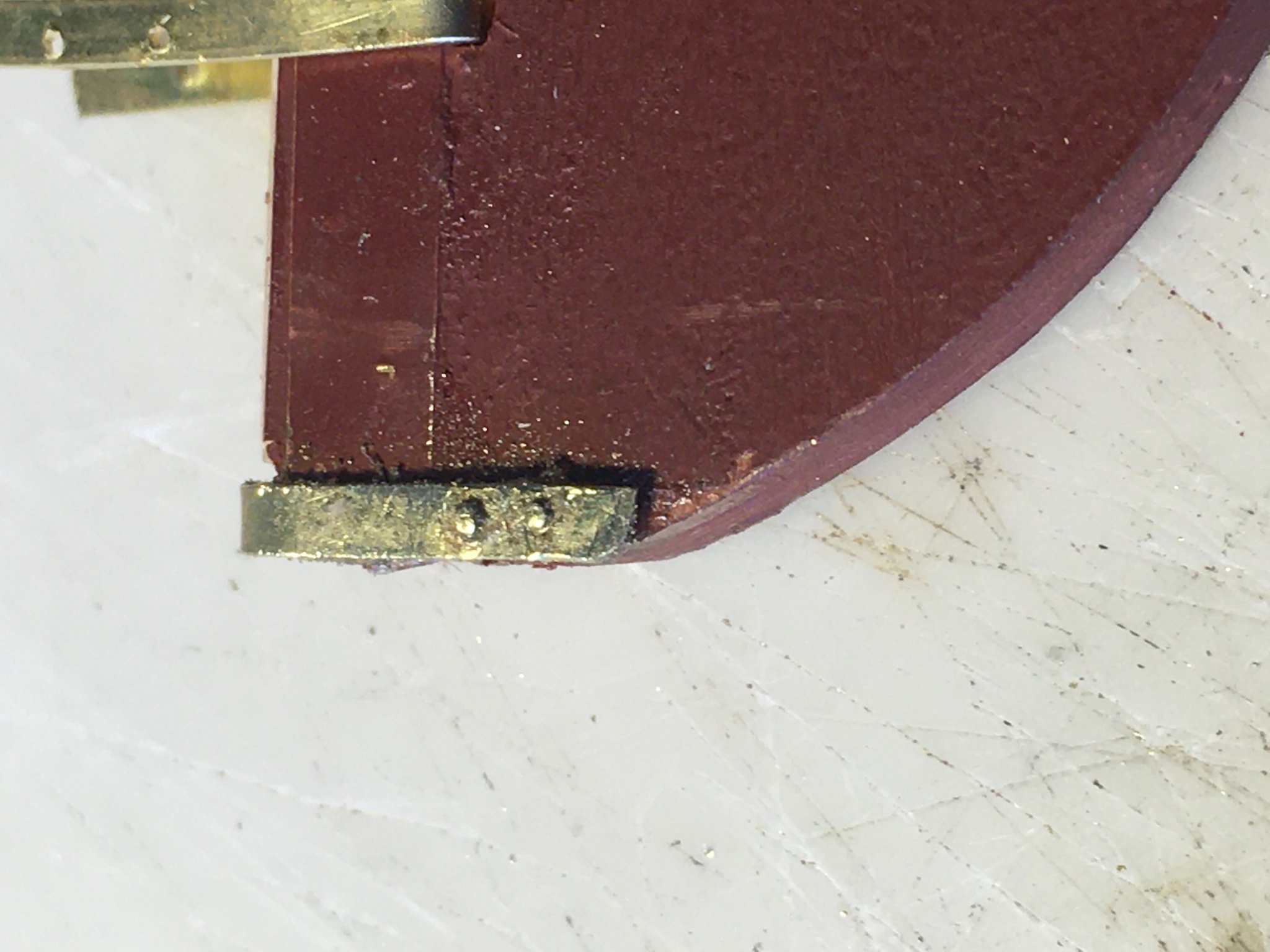
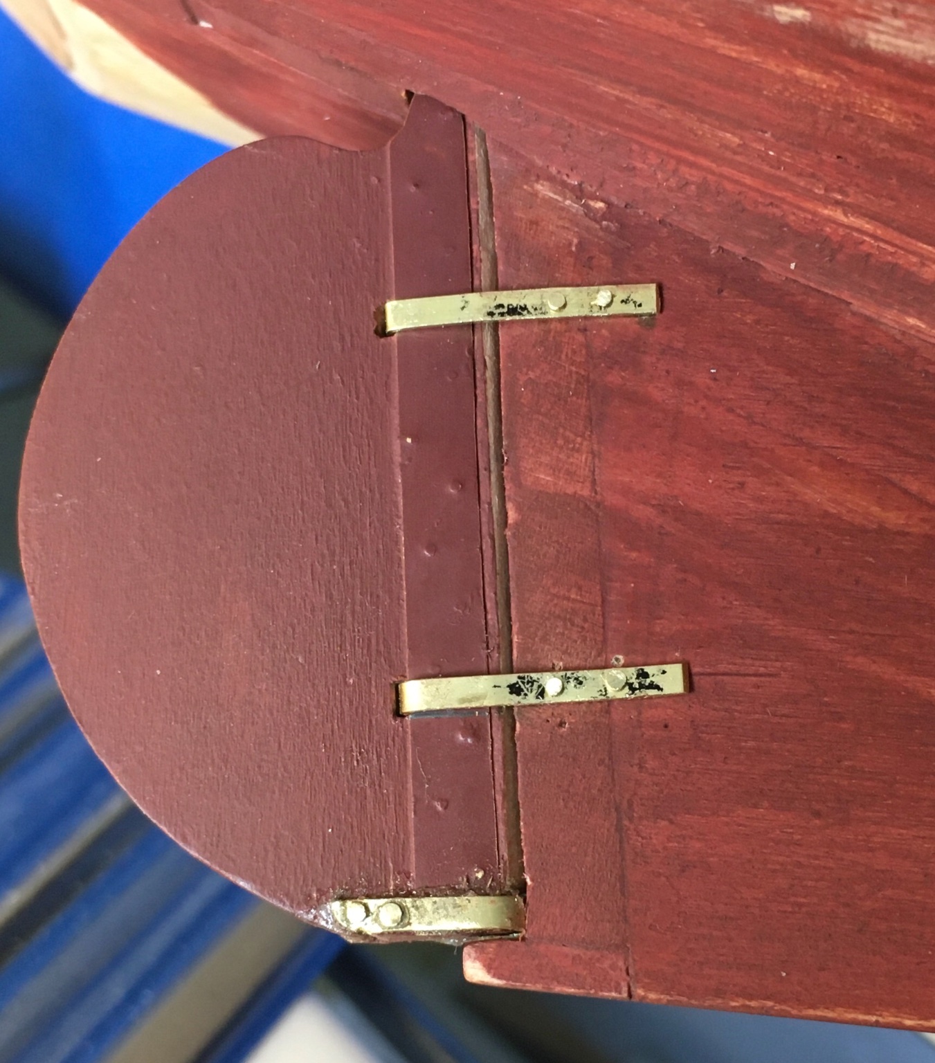
Thank you all for your kind comments and responses! Sea Hoss, I agree that a model is the sum of its parts, I try to treat each step as a separate project and hopefully all will meld together in a good final project. I like your build and have pinched a few of your ideas. It is interesting to follow the logs of the same model and learn from each one. A bit of a follow-up: I secured the top straps today using the method outlined above again using the nail set and it worked a treat. A few tips. Place the straps in position and insert the full size nails through the holes, I anneal the pins to about al dente so handle them with care while inserting, it is easiest to push them part way through and when a sufficient amount of the tip is protruding on the opposite side pull them through, less risk of deforming them. I then then hold the straps in place and apply masking tape around the perimeter them as I like to use a bit of epoxy in addition to the pin, the tape makes cleanup much easier. Once that is done I carefully lift one side and then the other of the strap high enough to apply the adhesive, I used an old scalpel. I then hold them in position, a self-closing tweezer works great, then cut off the excess pin and use the nail set to create the head with solid backing for the other side. I recommend cutting the pin quite short to prevent bending it instead of mushrooming it. I used 5 minute epoxy the first time and ended up with a mess trying to complete the task before it started setting up. I used 60 minute epoxy the last two times and it allowed enough time time for a less rushed and better job. I have struggled riveting four 4 years since I started modeling and finally think I have found a decent approach. If I live to 150 I may be able to solve some of my other challenges.😮
-
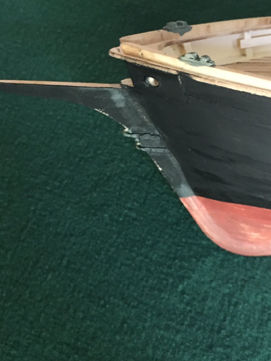
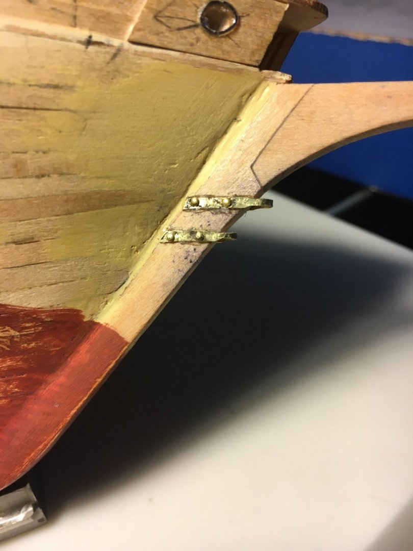
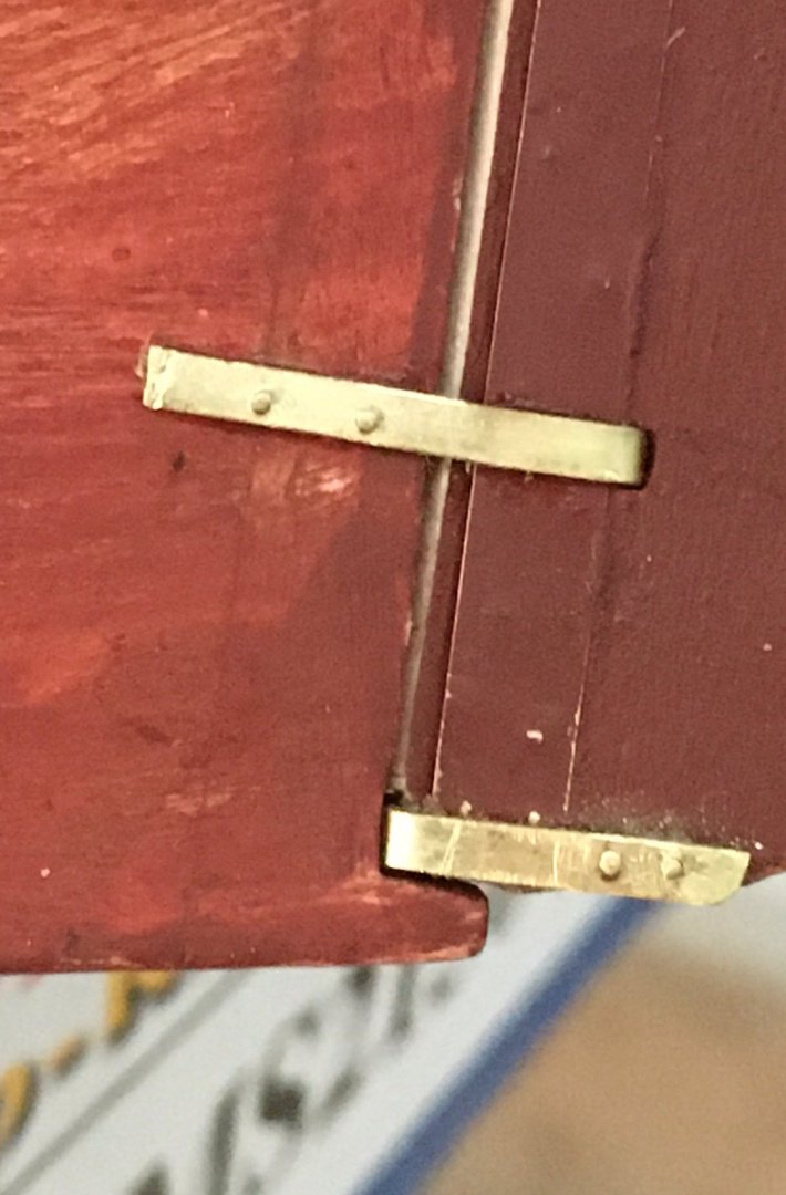
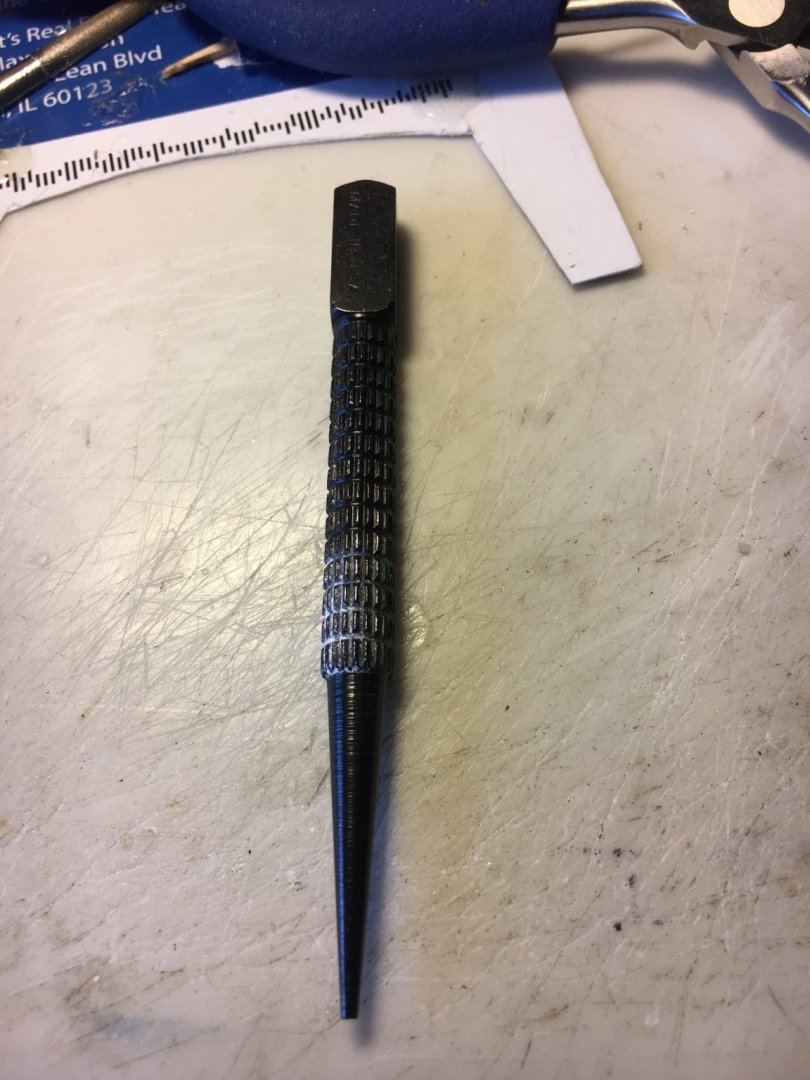
Results of another experiment: I worked today on the rudder and my first order of business was attaching the lower strap. I again reduced the size of the nail heads but should have made them smaller as you will notice in the pictures of the upper straps which I like much better. I heated the nails red hot to anneal them and inserted them. Very easy to bend so I recommend holding them with pliers right above where they enter and gradually work them in until there is enough to grab on the opposite side and pull them through. I mentioned in a previous post the difficulties in creating a head on the side opposite the normal head and thought about using a nail set as it has a small recess. I cut off the excess nail very short and used the nail set, it worked great and formed a very nice head! I did apply epoxy to the parts first. This was a Stanley nail set, they come in different sizes and this was the smallest I had on hand. It seems a very useful and inexpensive tool. https://www.amazon.com/Stanley-58-230-Piece-Steel-Nail/dp/B000BQPGYI/ref=asc_df_B000BQPGYI/?tag=hyprod-20&linkCode=df0&hvadid=241955516116&hvpos=&hvnetw=g&hvrand=11923333881675367596&hvpone=&hvptwo=&hvqmt=&hvdev=m&hvdvcmdl=&hvlocint=&hvlocphy=9021508&hvtargid=pla-383697233721&psc=1


-
Thank you both for the excellent suggestions! Will I will take a look at that site you mentioned. allanyed, I have tried copper wire with limited success. I do have a cup punch and as you noted it is much too large and unfortunately I don't have a lathe to modify it. I do have some nail sets that have a small dimple on the end so may try them. I have never used Liver of Sulphur but have tried Brass Black from Birchwood Casey after a pickling bath in Sparex with limited success, I might give it a go. Thanks again.
-
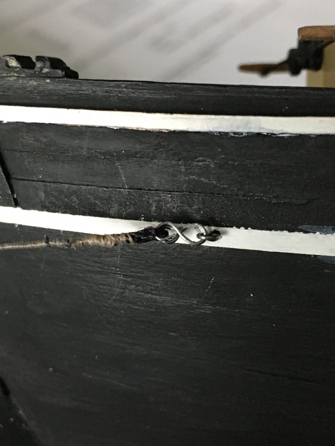
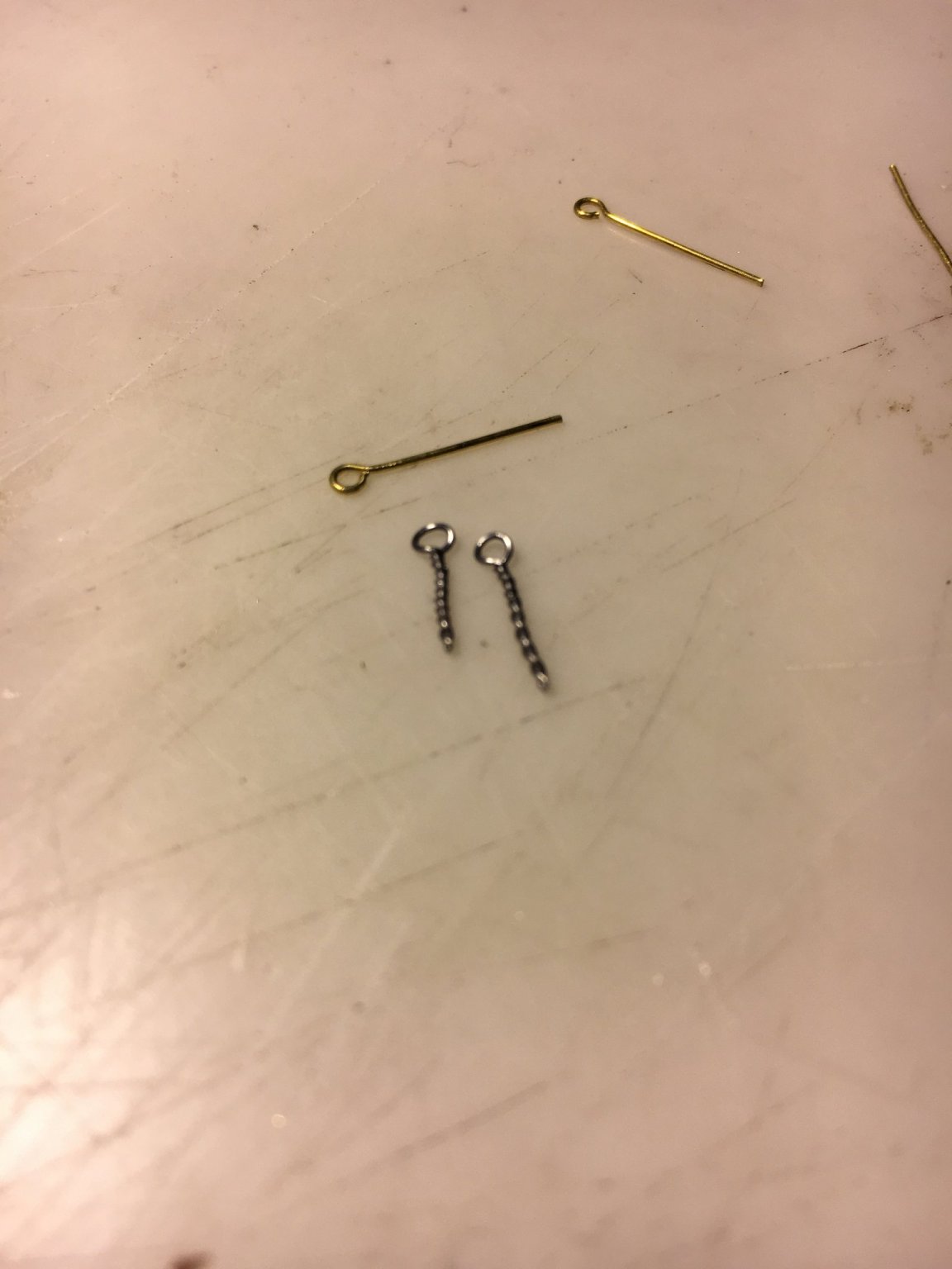
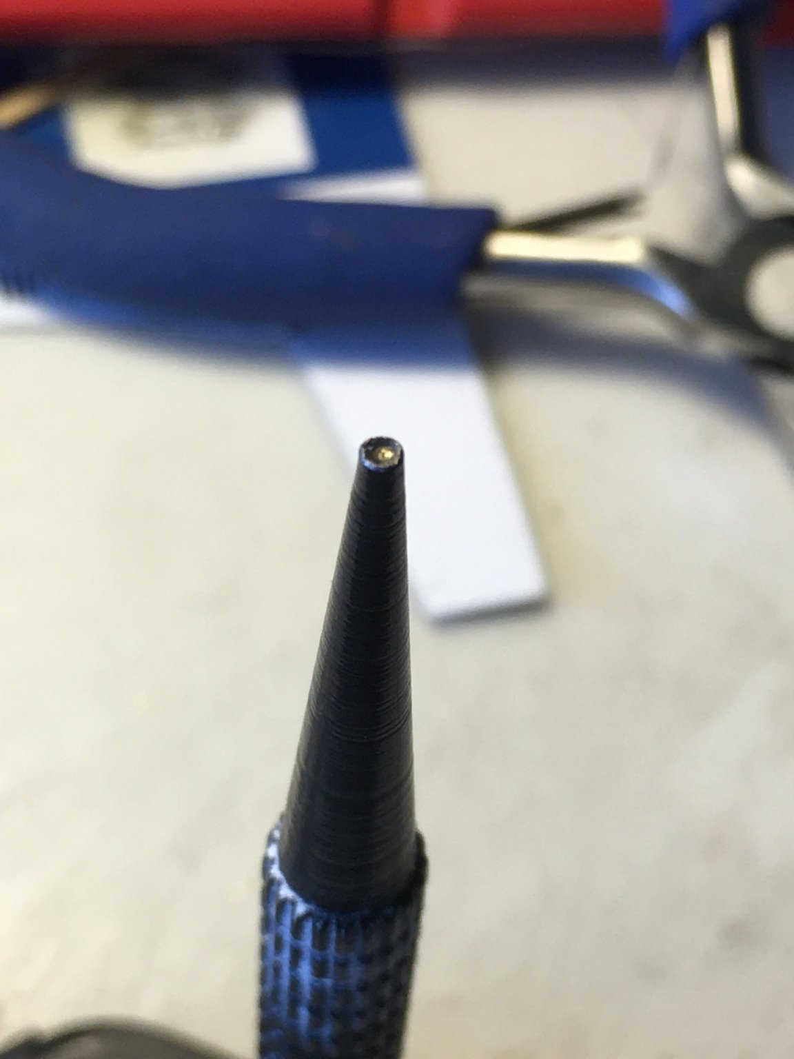
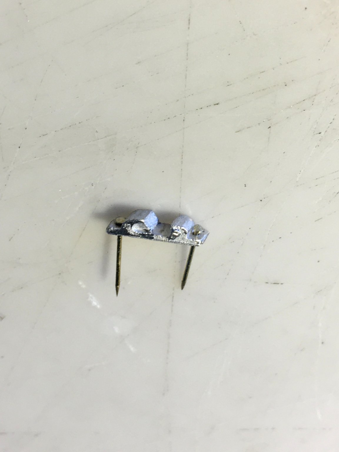
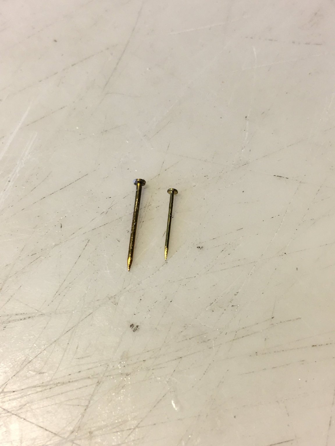
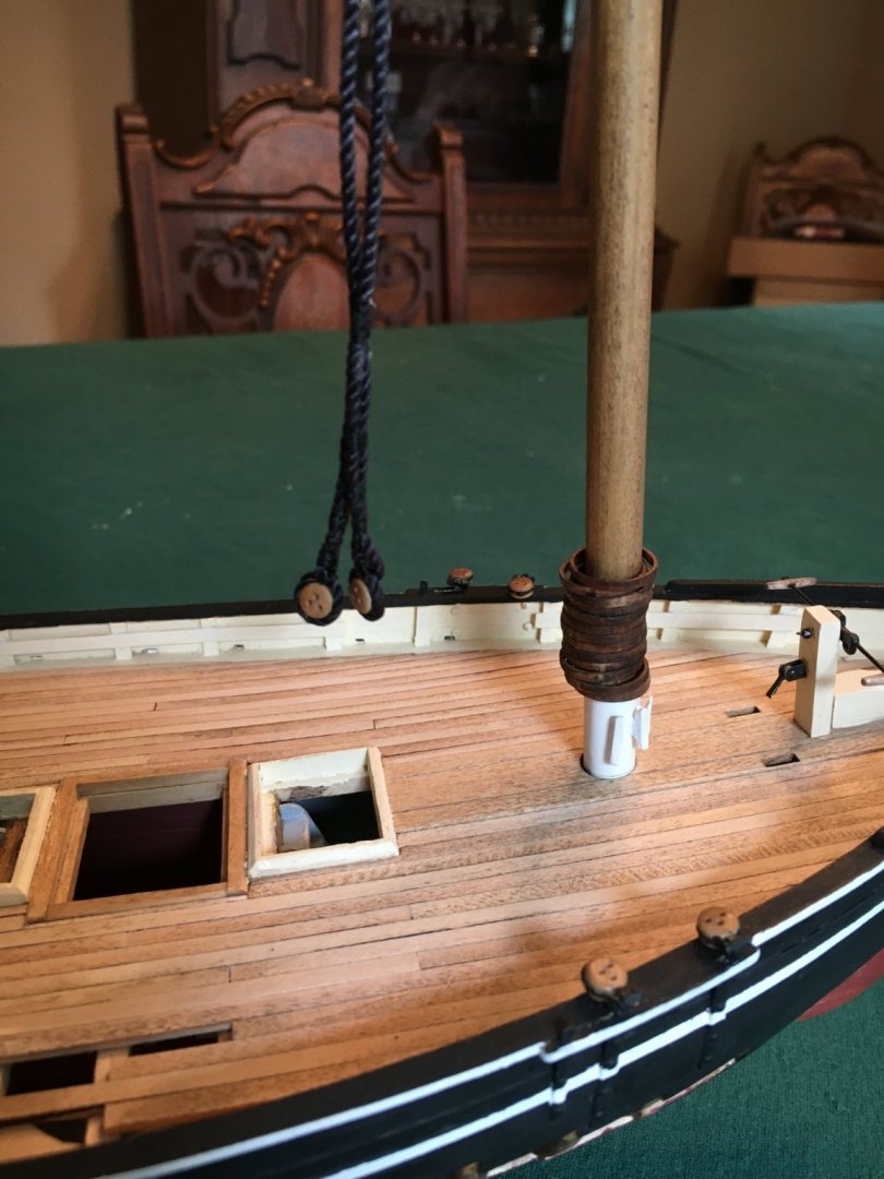
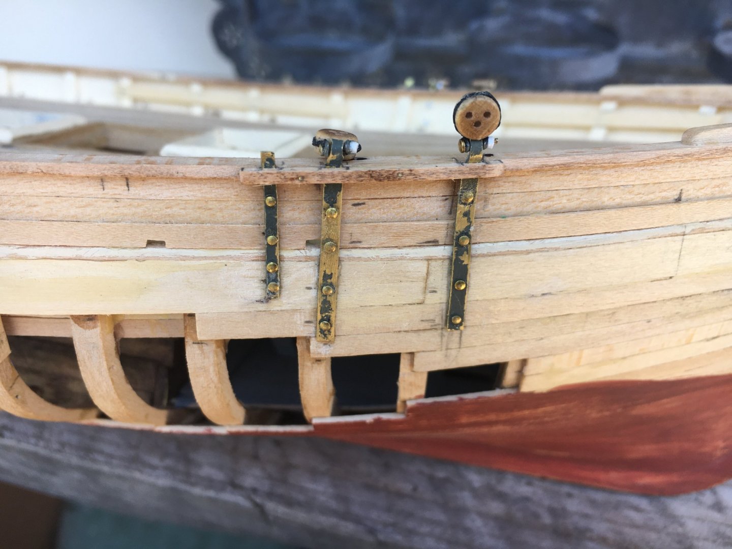
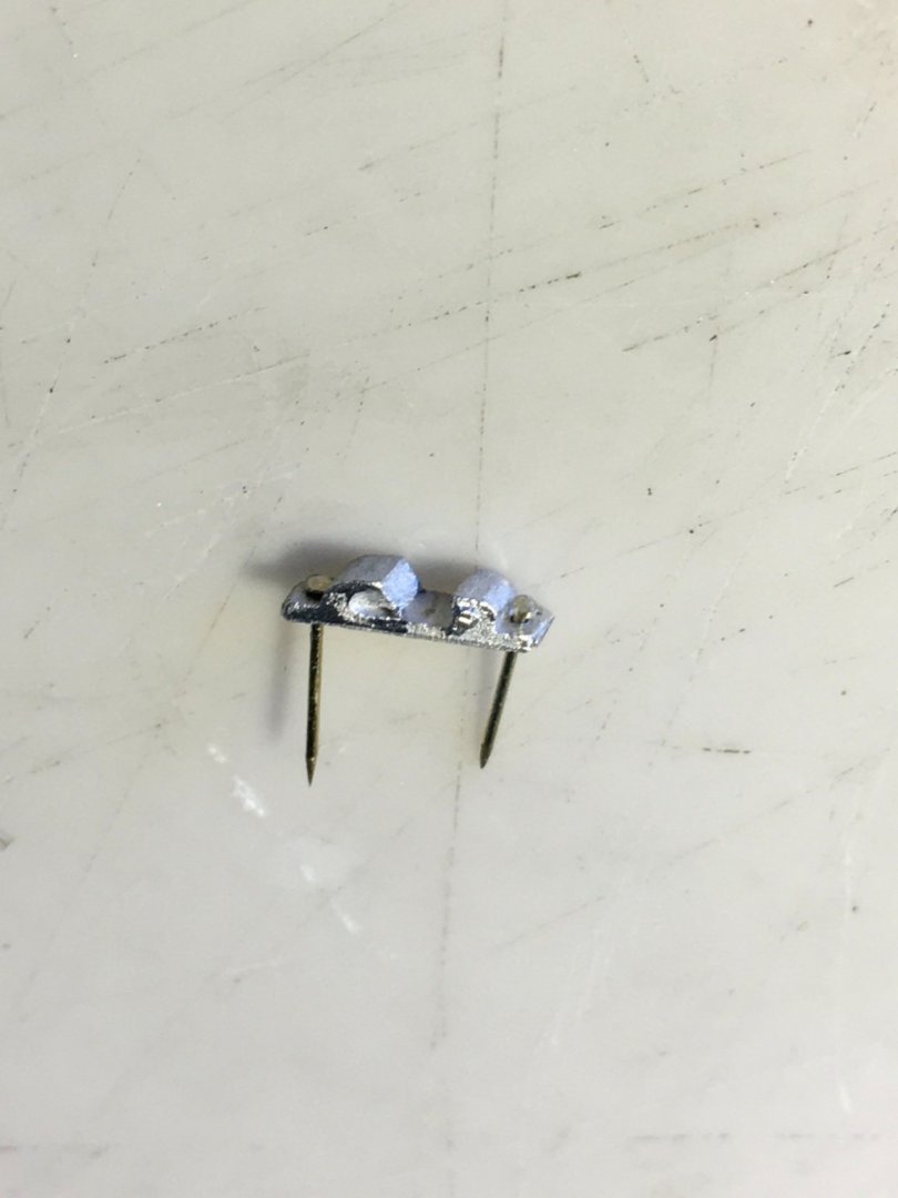
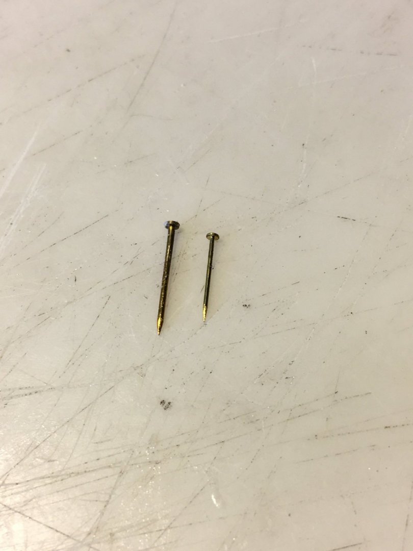
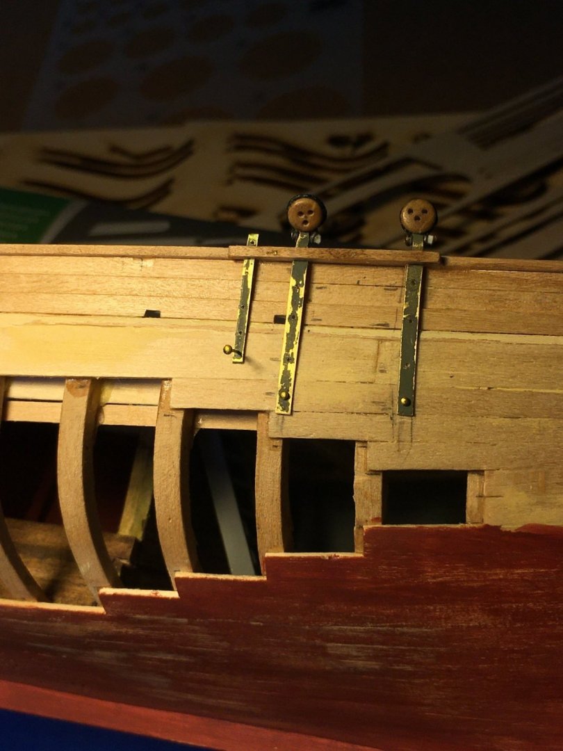
I worked on several odds and ends this weekend. Fastened the chainplates and deadeyes to the hull. I placed each in position and used fine masking tape around each and then fastened each with epoxy and brass nails. The tape sure made cleaning up the minimal amount of excess epoxy easy, highly recommended! I installed the skewed chocks at the bow area. I was concerned that with the small footprint of the metal chocks being attached to wood that the connection would be weak at best. I have some very fine brass nails so I chucked them up in a pin vice, placed that in a household drill and used a file to reduce the thickness and diameter of the head. I drilled holes at each end of the chock for the pin and installed them using thick CA on the bottom of the chock and a drop of thinner CA on the pin before setting them. Quite pleased with the result. I also painted the lashing rails and mooring bits inside the bulwarks. I have to reprime the chainplates and chocks. A note about the brass nails: The nails provided in the current Model Shipways kits are in my opinion way oversized for the models in most cases. Fortunately I have on hand some finer pins that work much better. The MS pins are .025" in diameter and the other pins I have are .0185" and much better at this scale. In the photo the current MS supplied nails and on the right the smaller ones I have on hand.

-
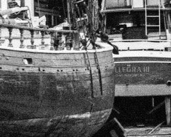
It is the Emma, here is the website. Click on Next Record on the top and a new picture appears, click on the picture to enlarge it. They are all pictures of the Emma although rigged as a schooner but much of the structure is the same.A great resource for those building the ECB! http://02d243c.netsolhost.com/htdocs/vex4/E5D8A155-F149-414C-A48F-796948282462.htm
-
Today I turned my attention to fitting the chainplates on the hull in preparation for painting the upper hull and bulwarks. I fitted them initially and then made the small piece that covers them and alas, they were too low to allow that bit to fit properly. Luckily, they were not glued or affixed permanently so I removed them, constructed the small bit, made a rebate for the chainplates in it and glued the strip in place. I then inserted the plates and redrilled the holes in the hull to affix them. A tip, the plans called for a strip the same thickness of the cap rail so I used a bit of waste from the matrix the cap rail came from. It was the same thickness, had the proper curve and with a bit of sanding worked great! Another concern I had was that the chainplates stood proud of the bulwark planking and looked a bit odd in that area. I found a photo of the boat and indeed they did stand proud! I am happy. The only issue is that one of the scuppers is misplaced according to the plans. I carefully measured the placement of the chainplates in relation to the mast so I apparently made a mistake on the scupper, I will probably attempt to fix that scupper if I get ambitious.


-
NiwotWill, thank you for your kind comments and advice, it is greatly appreciated! I have decided to leave the hull as it is and proceed with upper hull painting, nothing that can't be changed later if it looks bad. I will search for some photos of boats being rebuilt. I found a good photo of a refit of the ECB in progress, thanks for the suggestion

-
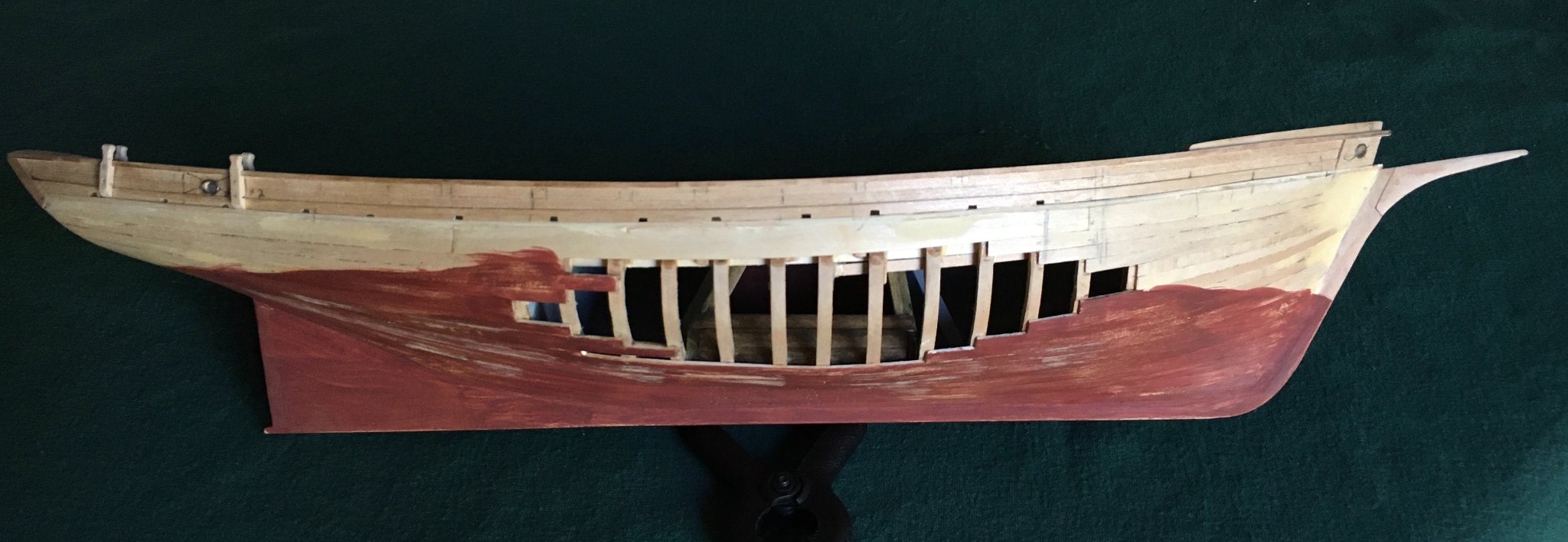
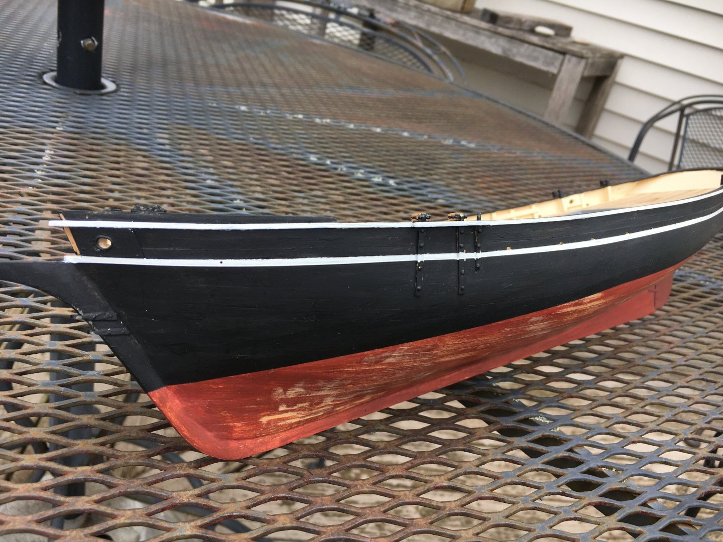
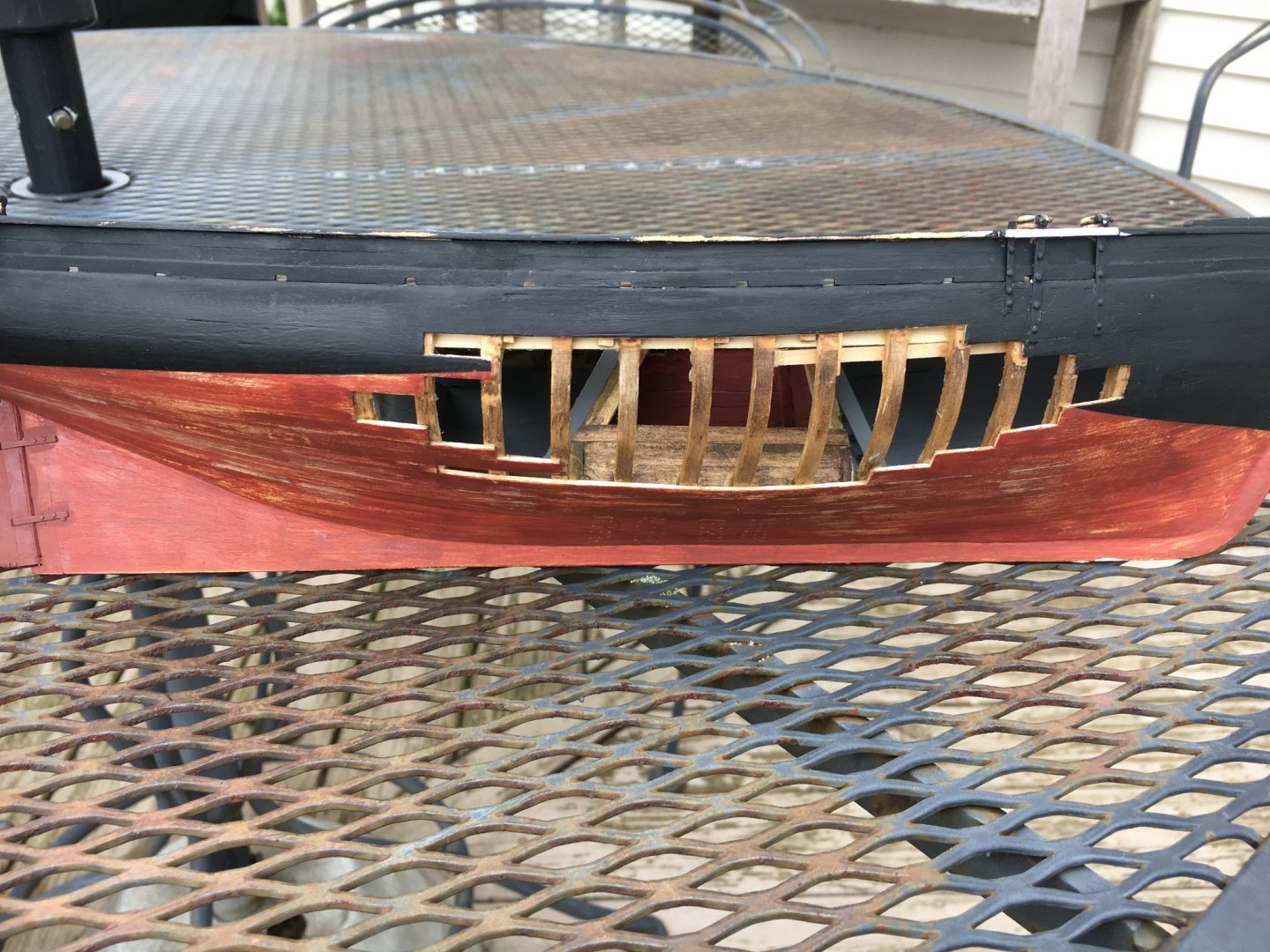
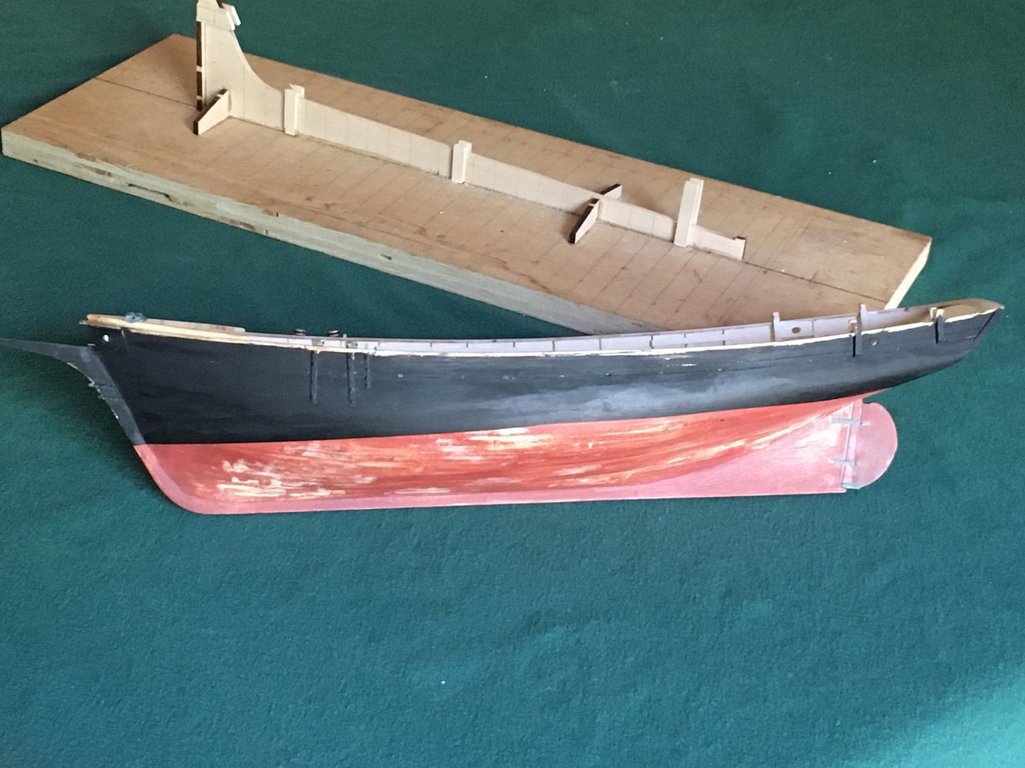
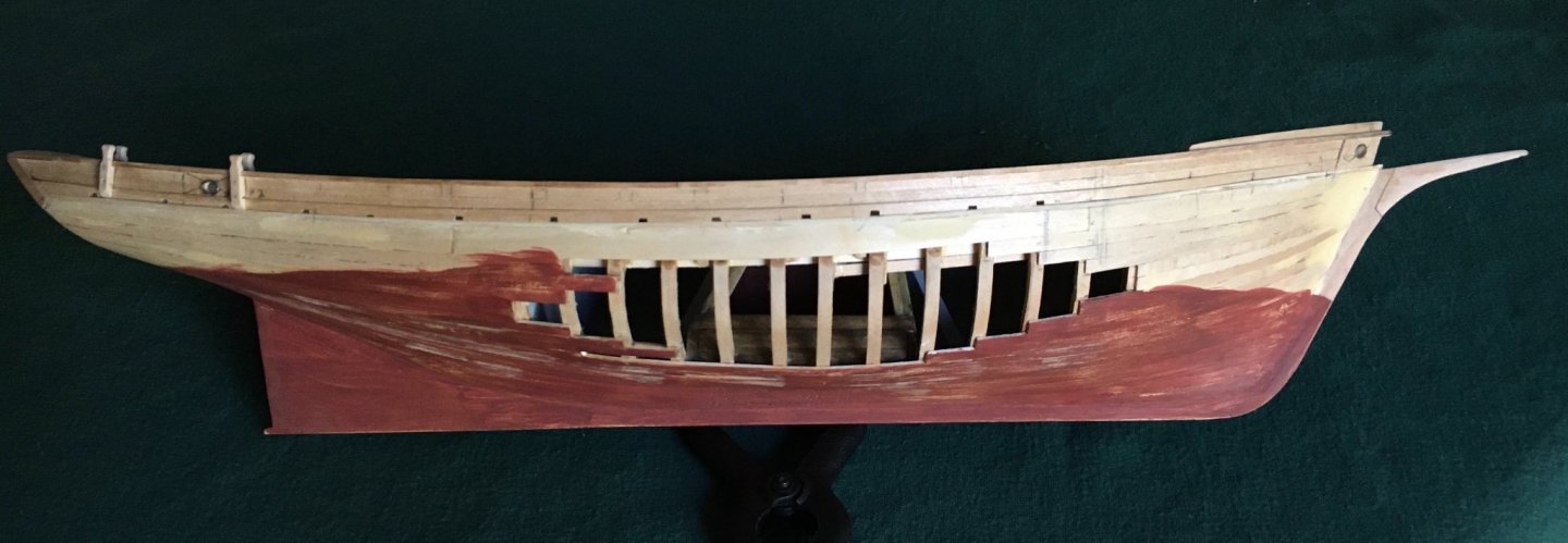
Opinions needed!! I started painting the bottom of the hull and naturally there were a few areas where the paint was a bit rough and a bit more filling was required. I did some sanding after filling and do like the look. I intend to build the ways and depict the ship as if undergoing a refit and repair with the hull being scraped or sanded to identify planks needing replacement. I have seen some other pictures of the model with a pristine painted hull and an open area where planks are being replaced. It seems to me that the planks would be replaced first and then the whole hull repainted. I have yet to scribe the waterline and paint the upper area black but I could weather that area a bit or assume a top to bottom repaint so the black paint didn't drip onto the anti-fouling painted lower hull. My deck parts and structures have been painted and look pristine so I guess they would fit into my top to bottom refit? All opinions or advice gratefully solicited.
-
Crack filling technique
turangi replied to Don Case's topic in Building, Framing, Planking and plating a ships hull and deck
I had very little clogging, I think wiping away the excess before sanding is the key. It removes the excess surface glue but leaves the crack filled and the sanding dust neatly fills the crack. I will post a bit more later about my technique, bit busy right now. -
Crack filling technique
turangi replied to Don Case's topic in Building, Framing, Planking and plating a ships hull and deck
I have had good luck with applying glue, both PVA or CA to the gap and immediately sanding and the sawdust created will fill the gap right then. When planking if glue squeezes out between the planks, wipe it level and a bit of quick sanding fills any gap. Saves an extra step. -
Great job on the stanchions! As I recall I remade the knightheads at least once, they look a simple part in the plans not so much in execution. I did use a Dremel with a very small bit to open up the below deck area. I would suggest trying to get the below deck portion correct as much as possible, then trial fit a bulwark plank or batten to set the proper angle of the knighthead and finally lay the cap on the stanchions to determine the proper height from the first stanchion to the top of the bowsprit and scribe a line on the knighthead and trim it to that height. You will have to temporarily fit the bowsprit in place to set the meeting angle of the knighthead, cap rail and planking. It took me a lot of fussing to get it to my satisfaction. There are several angles to conform to and taking them one at a time seemed to help.
- 161 replies
-
- 1
-
-
- Model Shipways
- Emma C Berry
- (and 1 more)
-
Your build is looking great! I delayed on installing the bulwarks as long as possible as I thought it would be very challenging and error prone. I finally went ahead and it was actually quite enjoyable. A few of my challenges and solutions as best I could manage: I built a simple gauge to set the stanchions to the same height. I used some tiny wedges to hold them in proper position as needed, on the side with some planking omitted it was much easier to apply glue and see where it was in relation to the stanchion, where there was planking and ceiling in place I used extra glue and hoped for the best! The cap rail didn't align completely and did a bit of judicious edge bending to conform to the run of the stanchions and bulwarks. The directions indicate installing the cap rail before the bulwark planking, it seemed better to me to install the planking first to the stanchions, sand the tops level and then install the cap rail, more glue area for the cap and everything is level Have fun and I look forward to your report.
- 161 replies
-
- 1
-
-
- Model Shipways
- Emma C Berry
- (and 1 more)
-
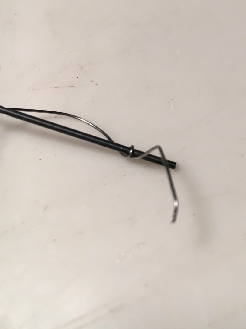
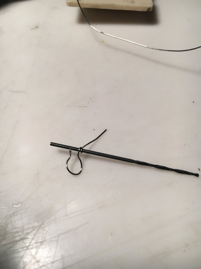
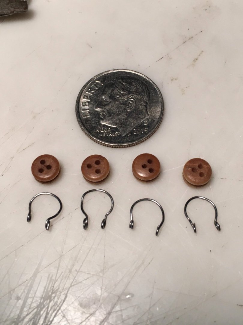
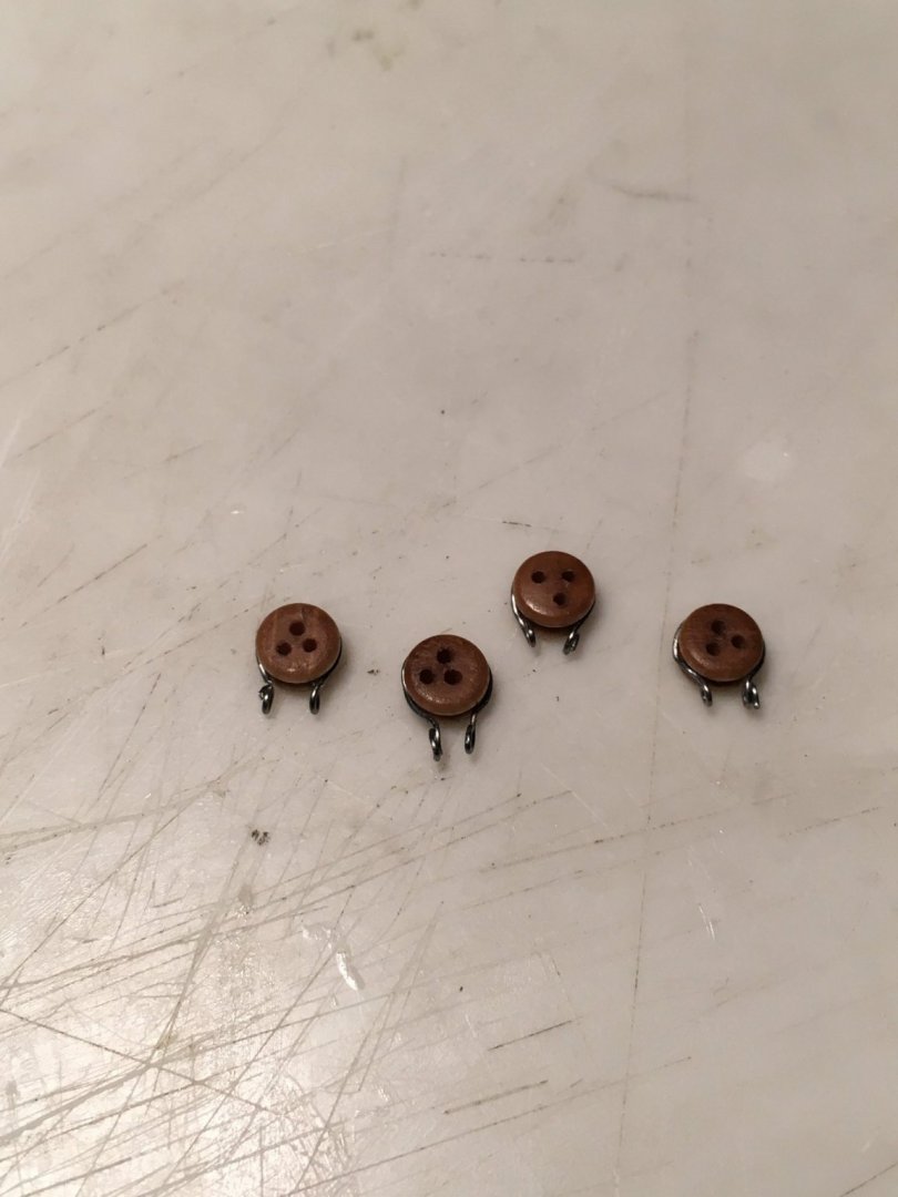
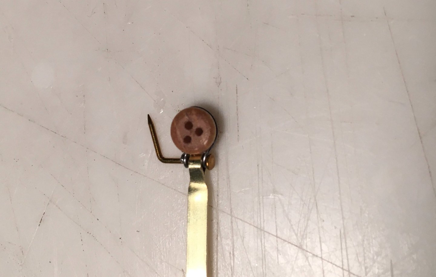
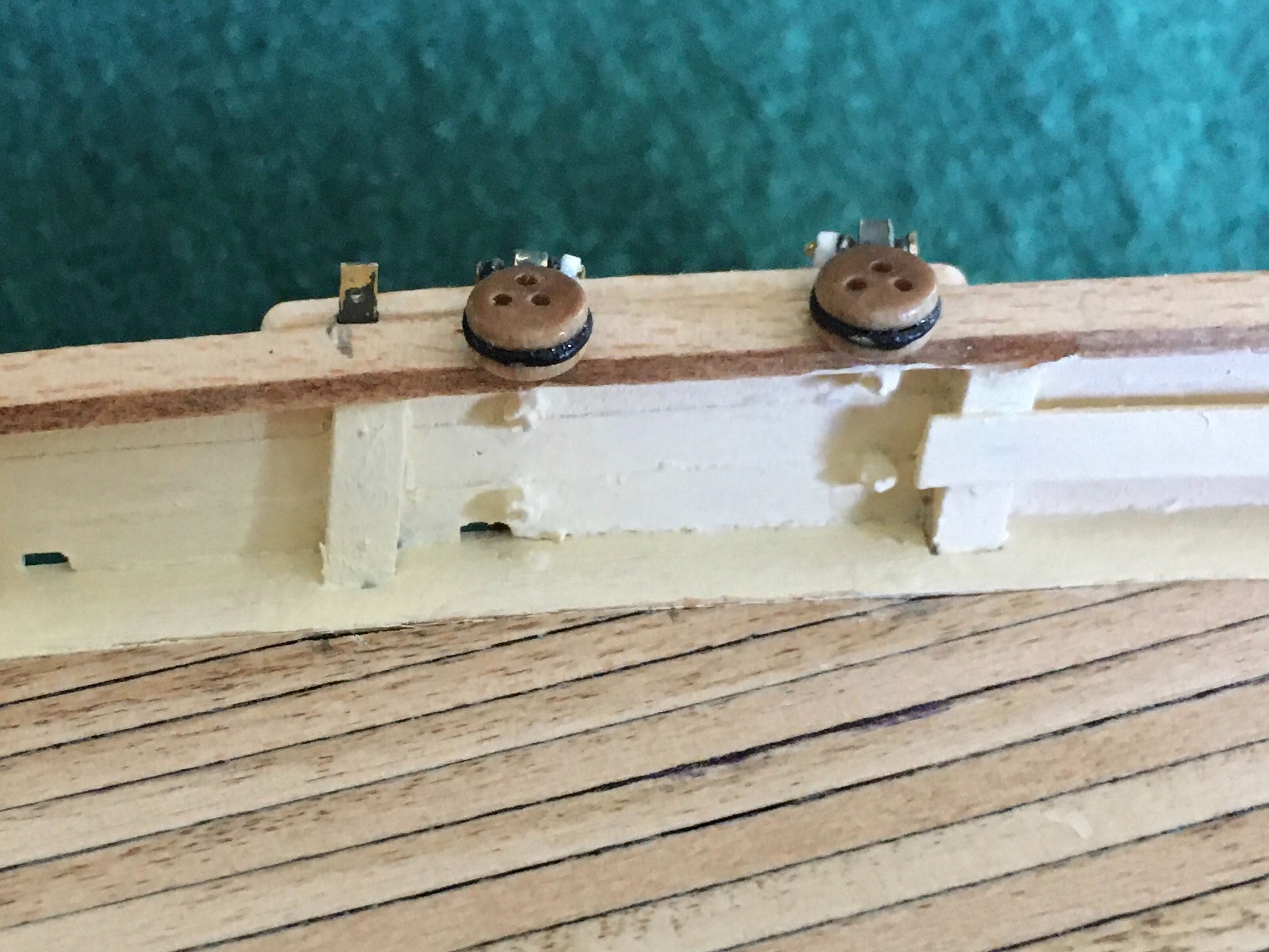
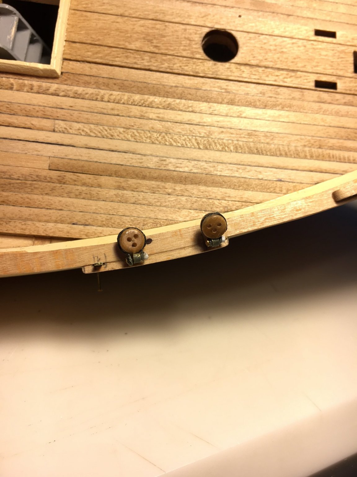
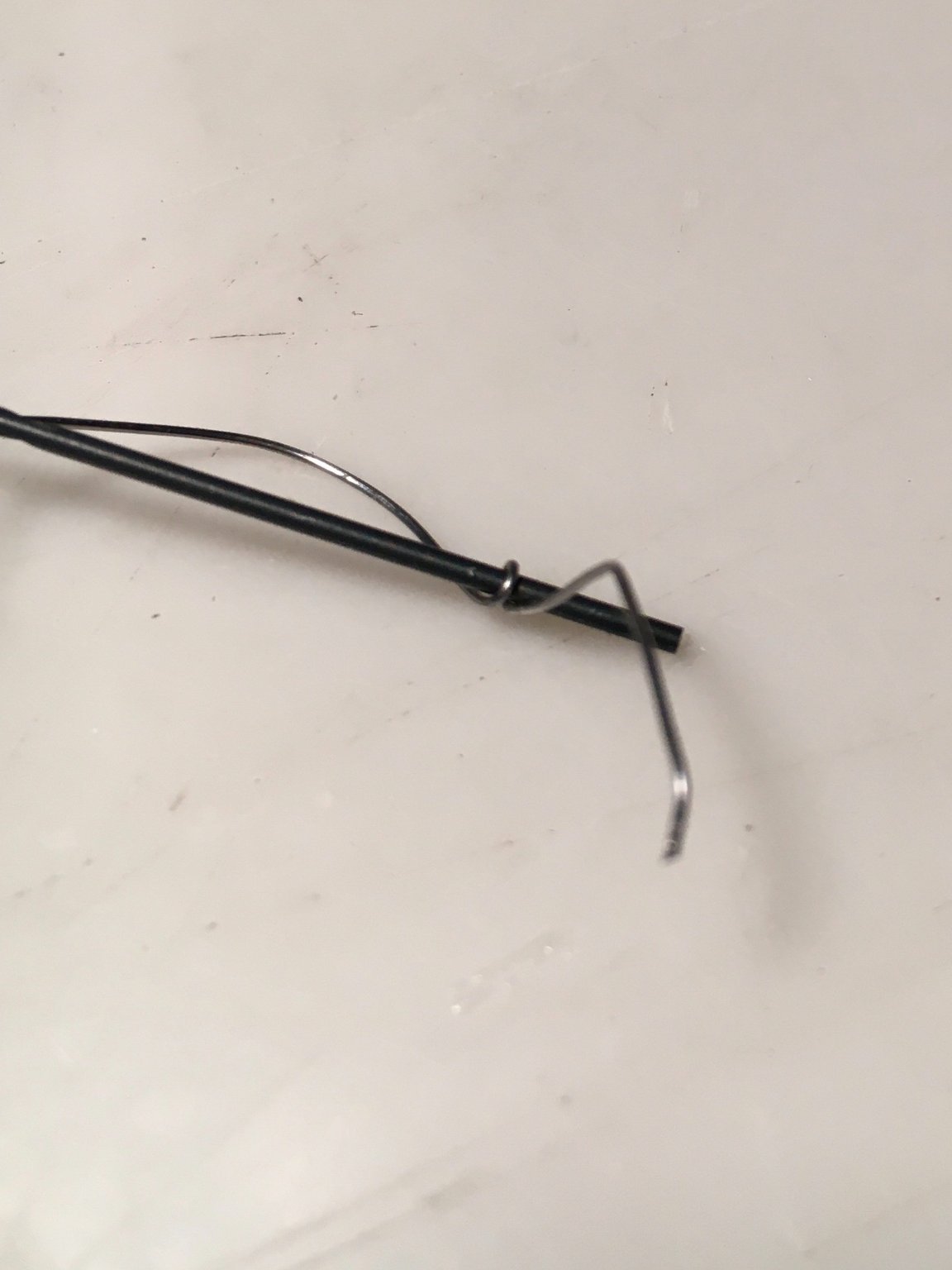
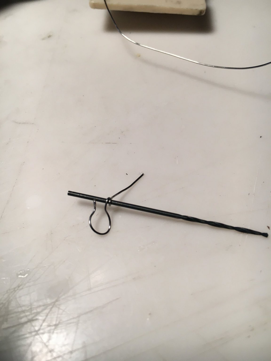
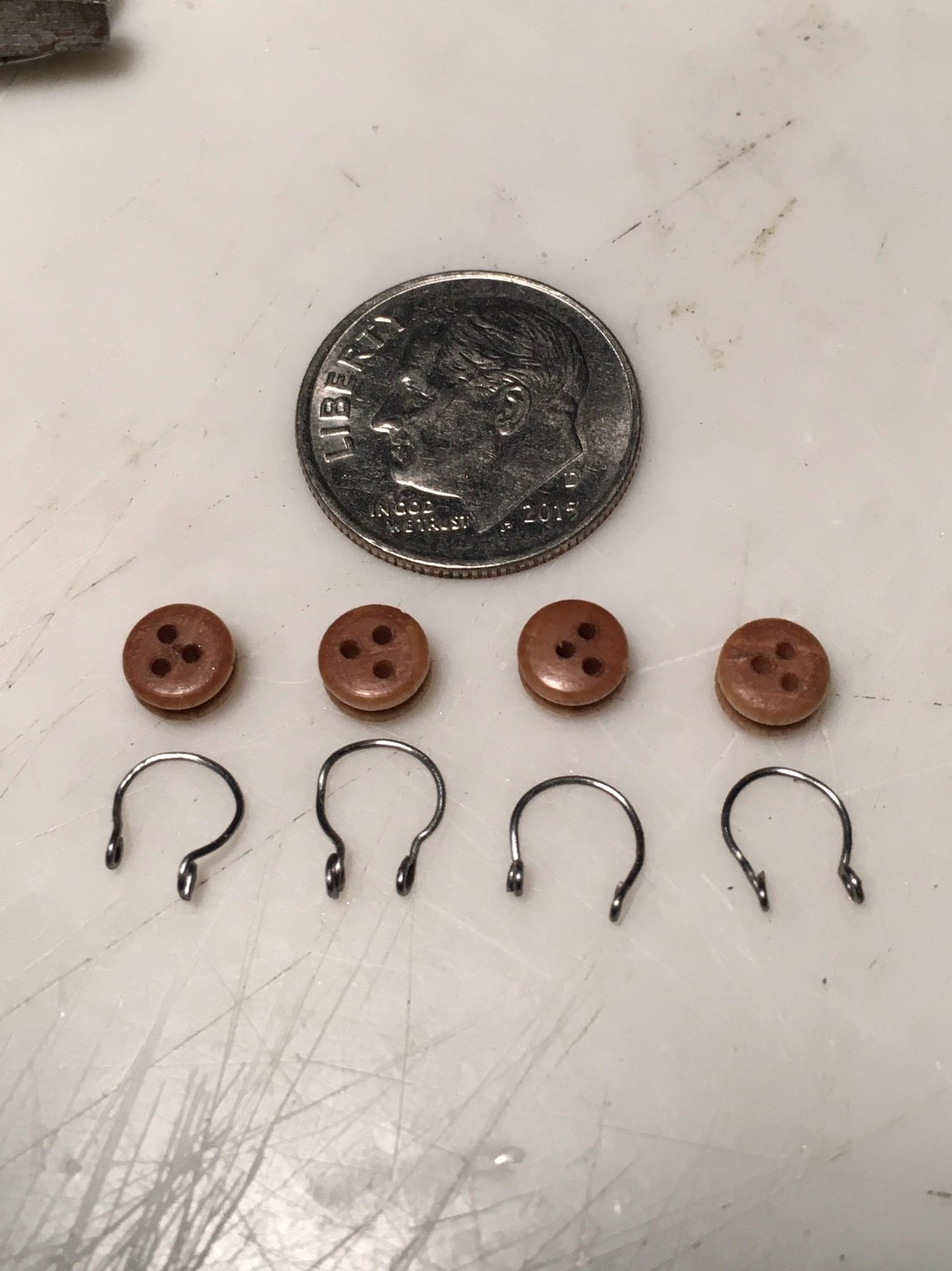
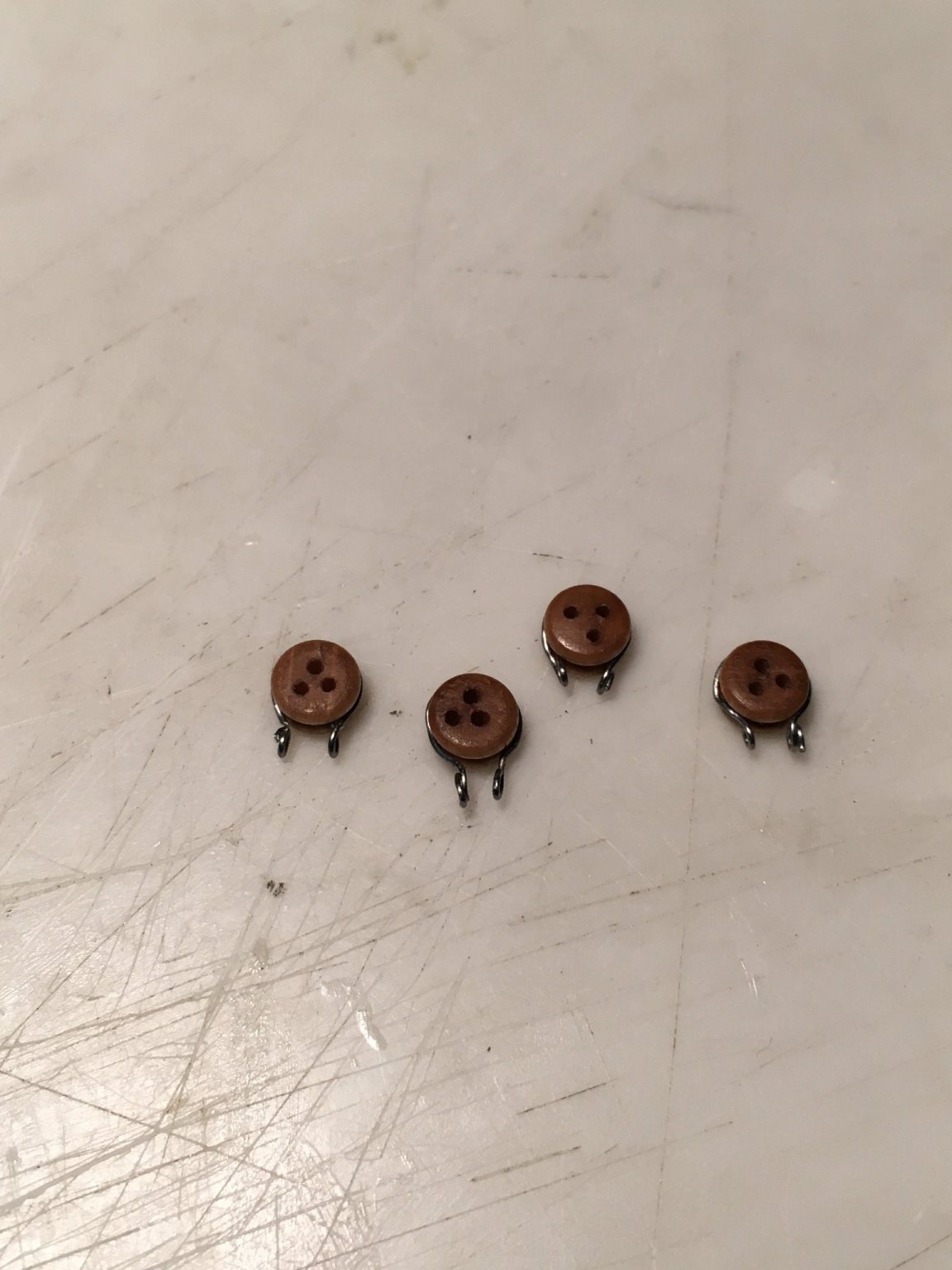
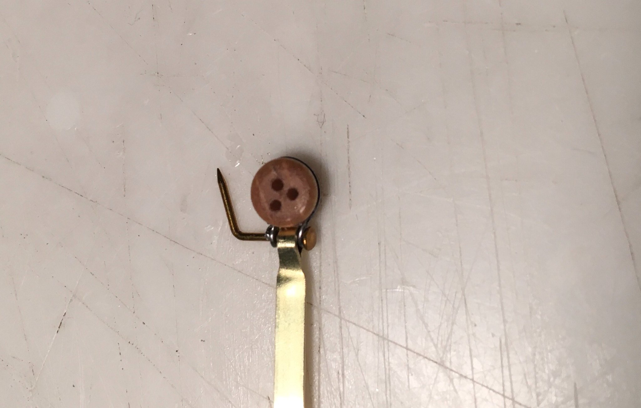
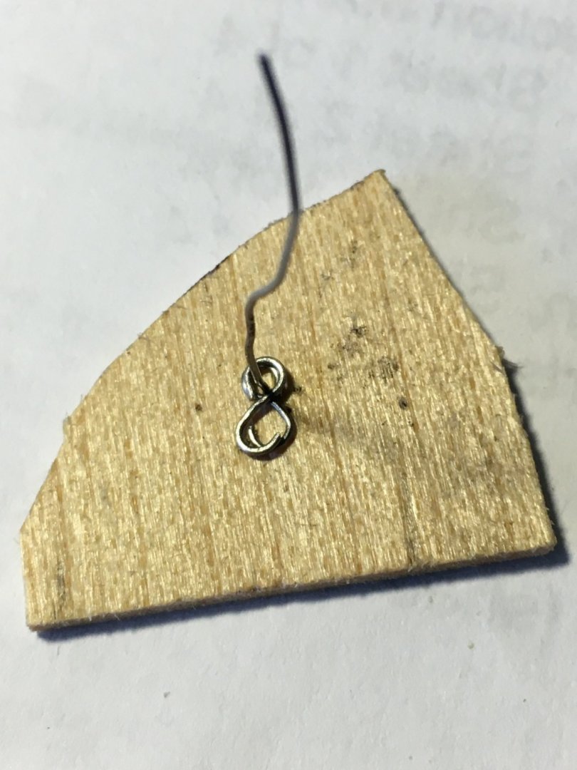
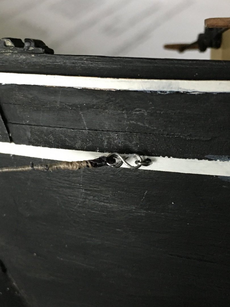
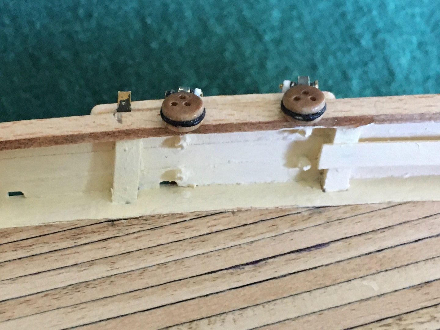
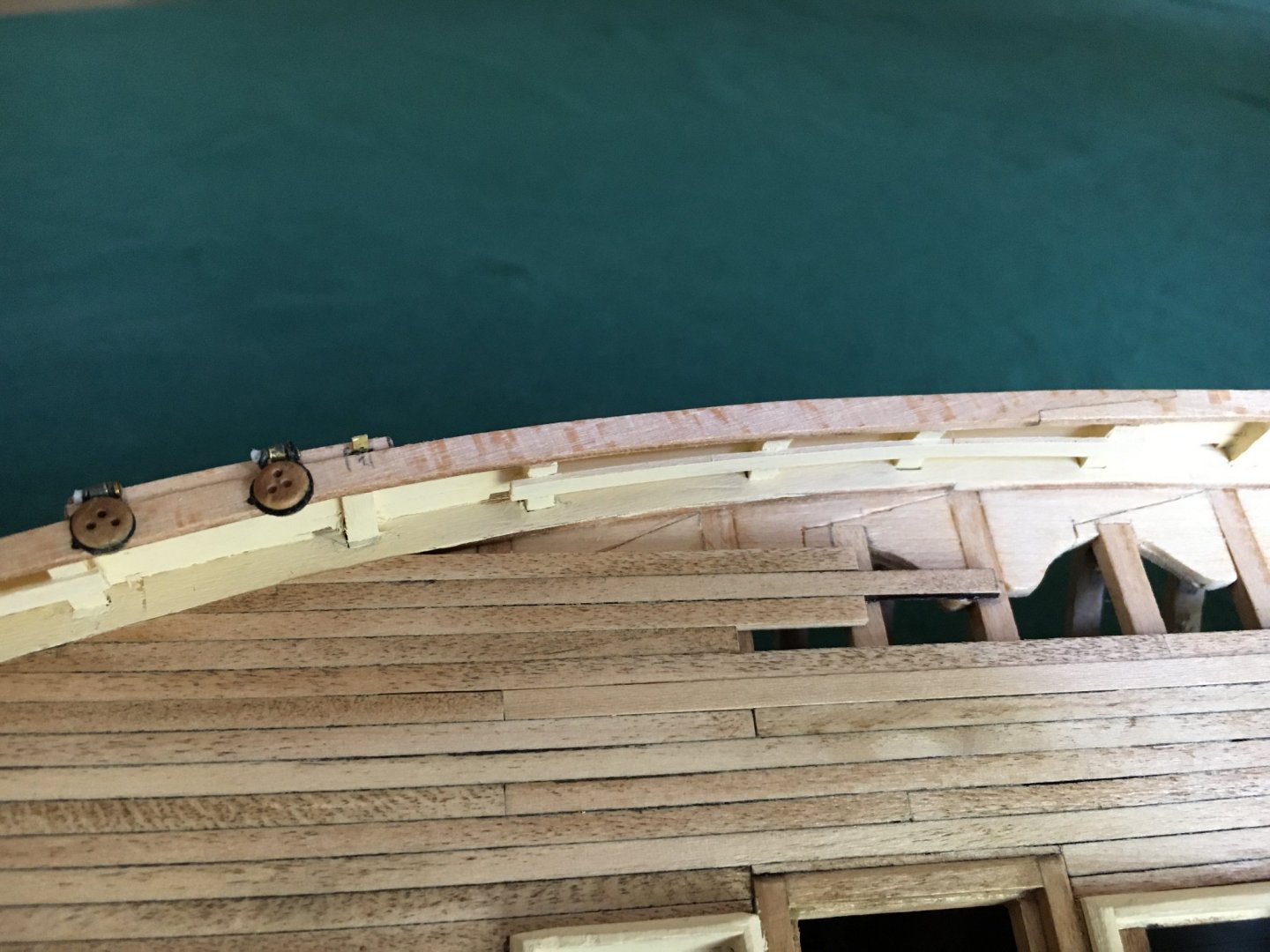
Today I worked on constructing the deadeyes that attach to the straps on the hull to support the mast, I have never made deadeyes before so this was a new adventure. The plans and directions had a paucity of information on their construction other than they appear to have a metal strop. I initially tried to make the strop from copper wire and flattened the ends to allow a hole to be drilled for a connecting pin, this was a failure as the flattened area was very thin, fragile and easily broken. I decide to try some soft steel florist wire and that seemed to work. I twisted one end around a small drill bit, shaped it around the deadeye and then twisted the other end around the drill bit which gave me two eyes to pass a pin thought to attach to the hull fitting. There is a picture with the pin in place and I will work on the pin to reduce the head diameter and flatten it some. I haven't decided how to treat the other end of the pin yet. Strops have been painted and I will attempt a trial assembly tomorrow. It all seems a bit crude and any suggestions will be gratefully welcomed on the whole process of constructing deadeyes!!! The scary part is that these are the large deadeyes, there are smaller ones to be worked on. I may have to go scouring for spider webs to get strop material. Interesting, the deadeyes rather look like me working on them!😮