DONATION DRIVE - SUPPORT MSW - DO YOUR PART TO KEEP THIS GREAT FORUM GOING!
×


turangi
-
Posts
276 -
Joined
-
Last visited
Content Type
Profiles
Forums
Gallery
Events
Everything posted by turangi
-
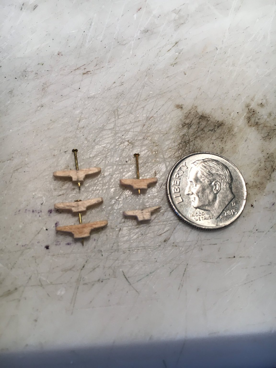
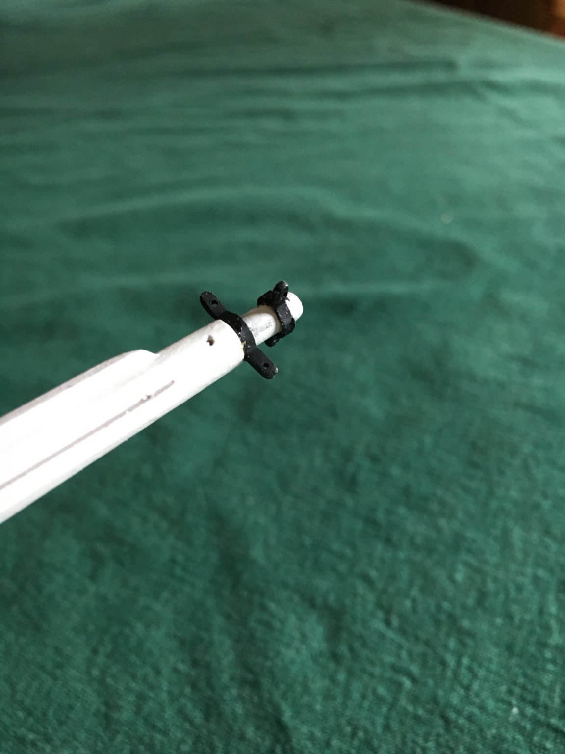
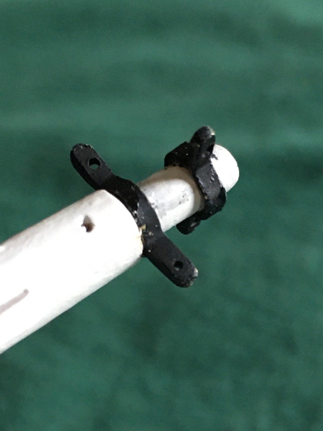
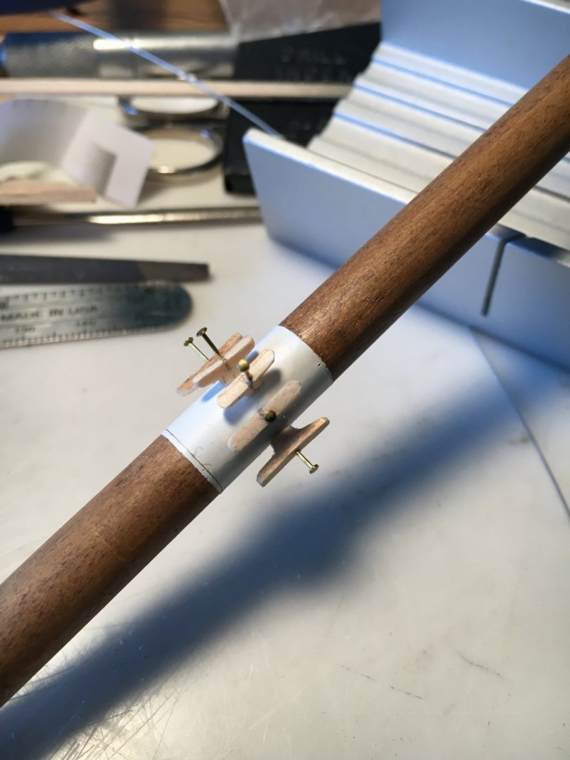
 I spent some time today making the cleats that attach to the mast. It was challenging but I only managed to destroy one during fabrication. I drilled holes in the cleat and mast for pins, the pins look huge in the photos but were .018" in diameter. I fitted them temporarily in position, then cut off the heads, filed them square and secured them with CA applied to the pin and cleat. Fun little project!
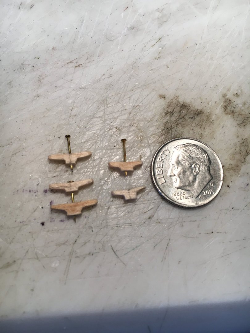
-
Yours turned out well but they certainly are a challenge!
-
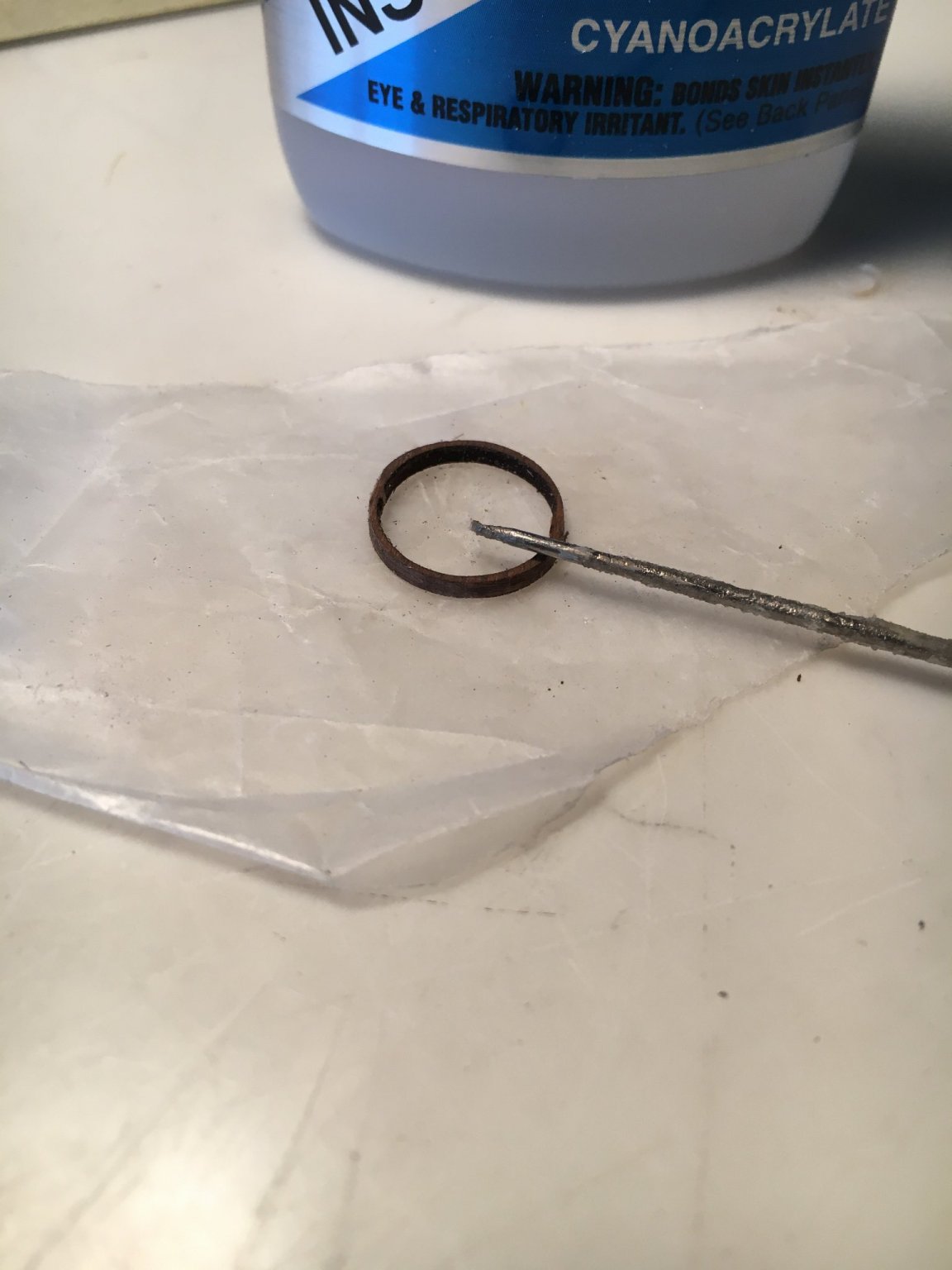
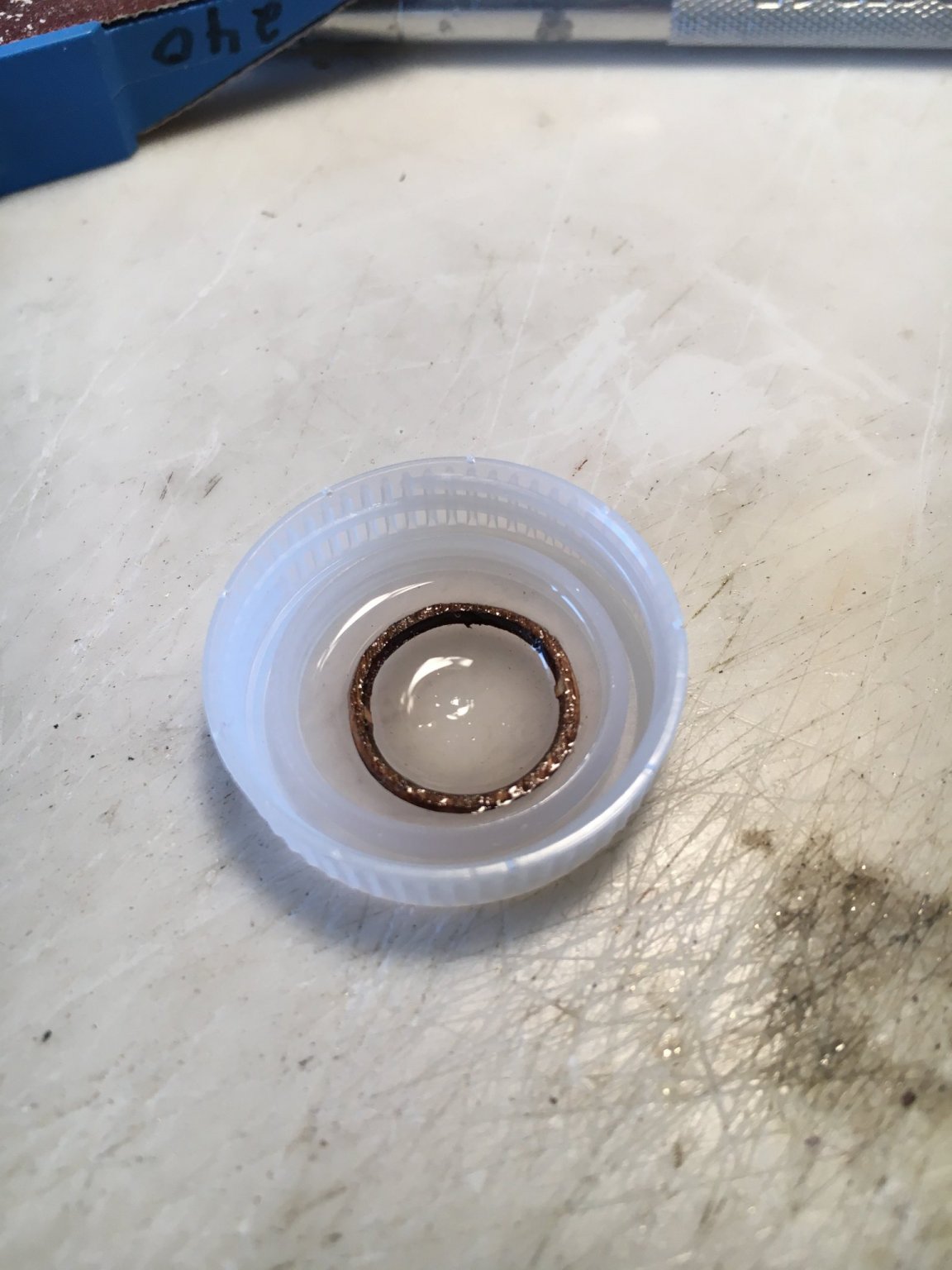
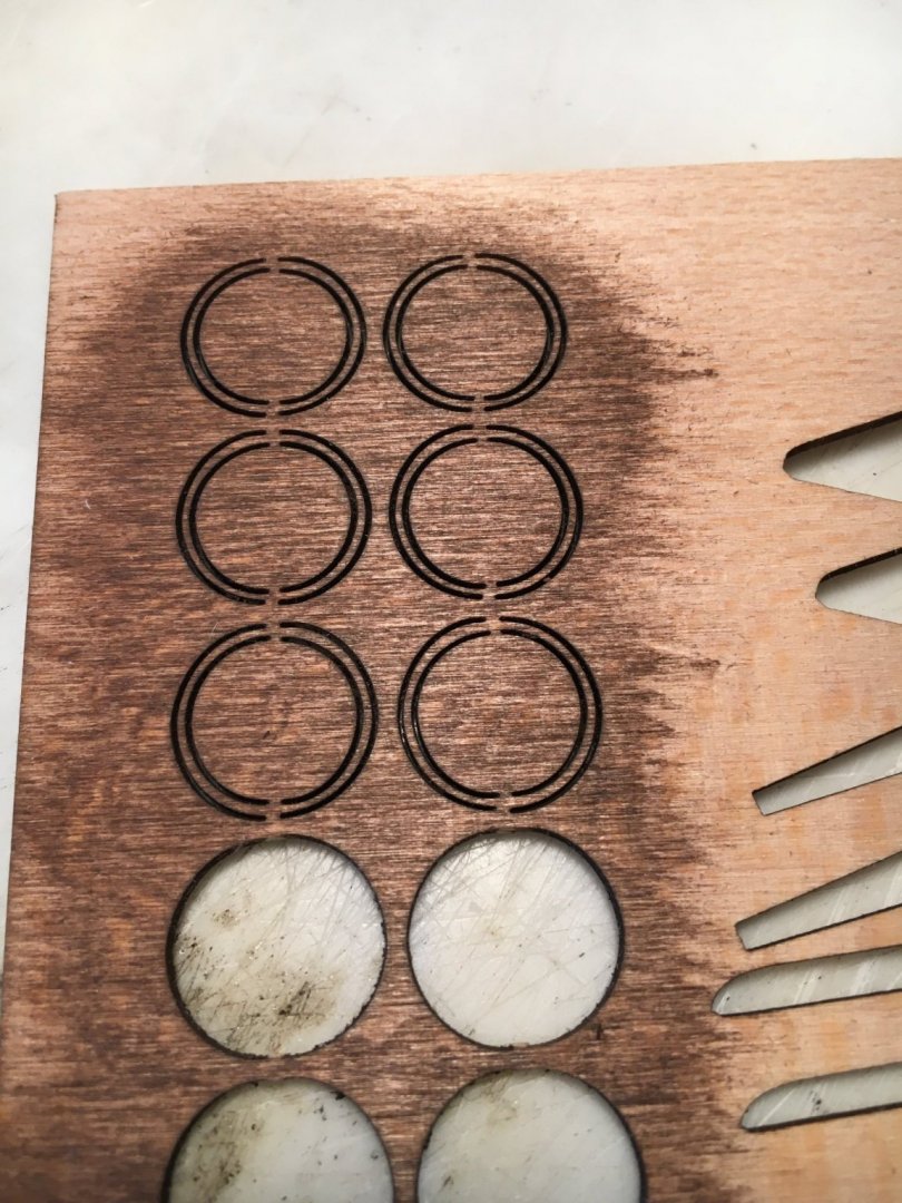
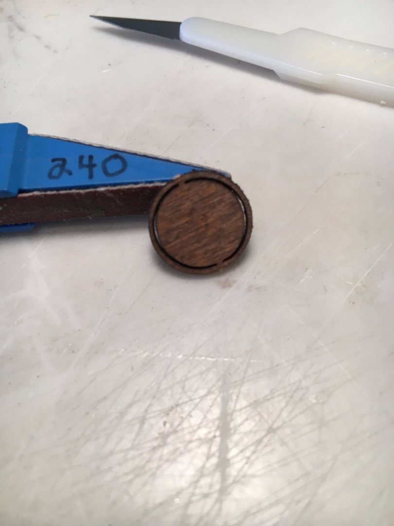
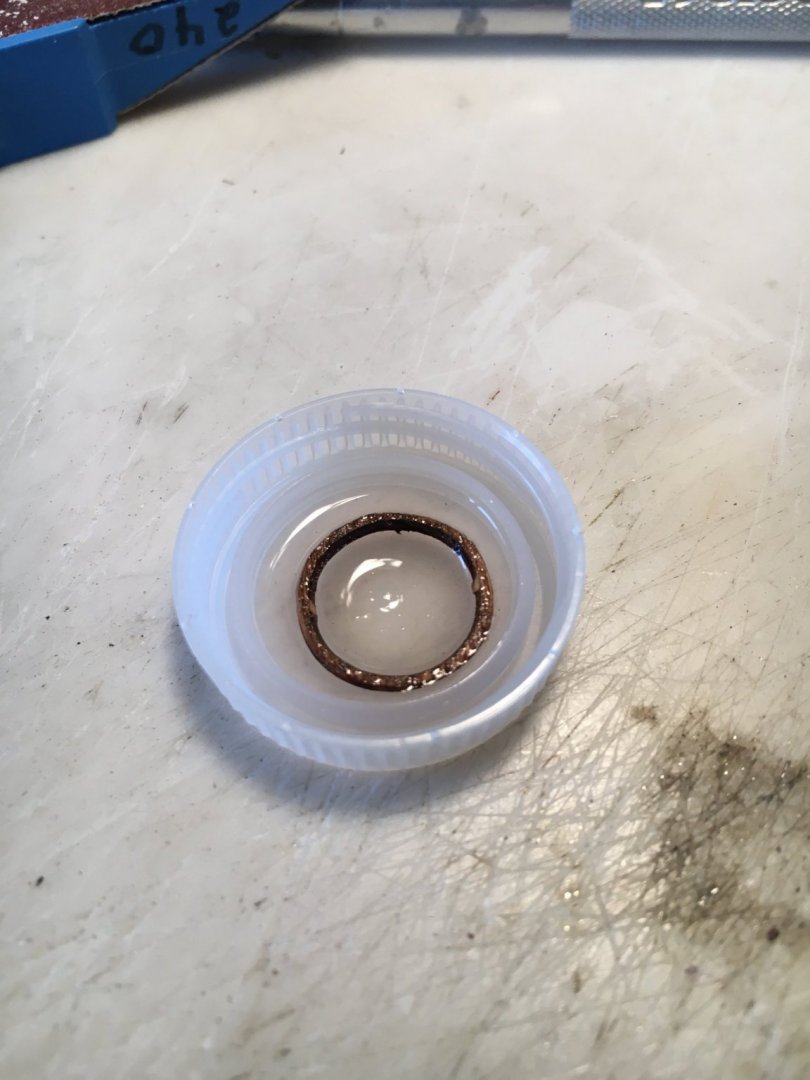
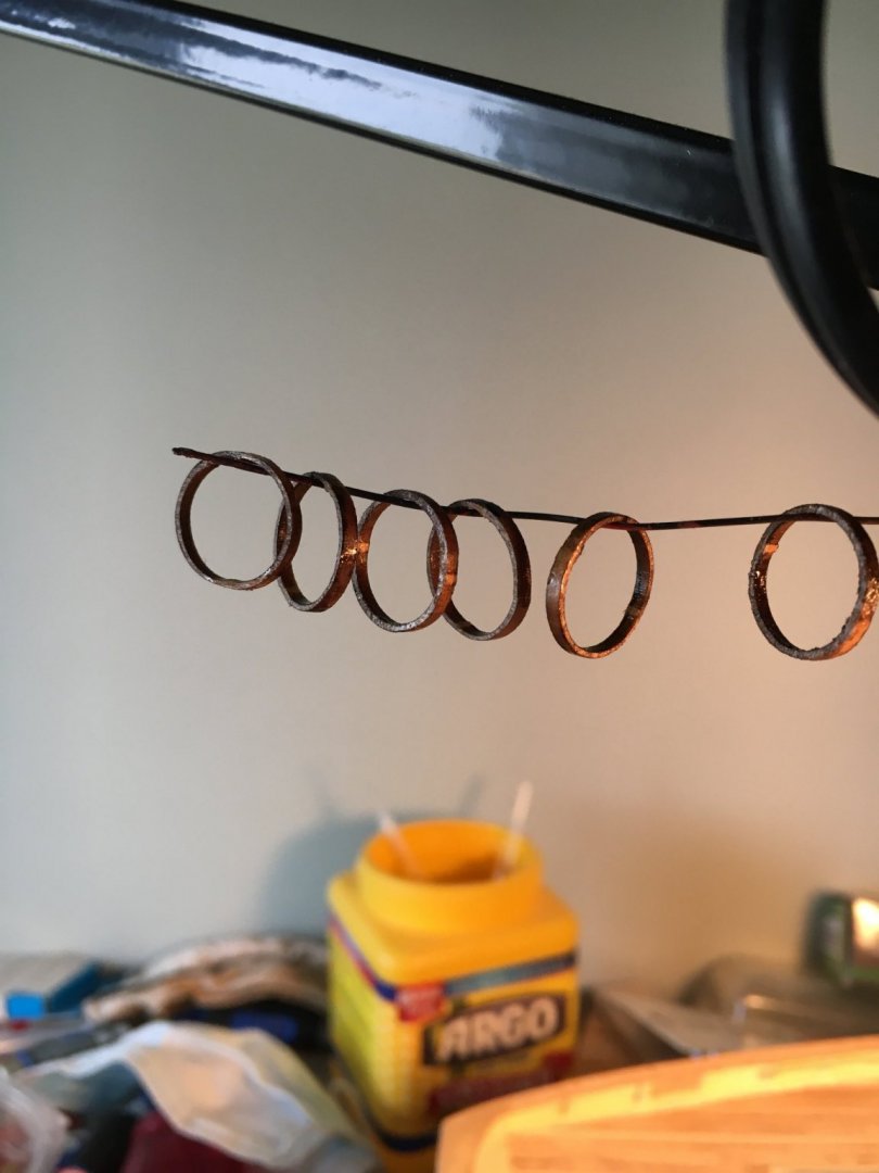
I have stained and painted the mast, no photo as it is quite straightforward. I turned my attention to working on the mast hoops. These hoops are so delicate as supplied I can't imagine they could survive being used to rig a sail, thankfully I am not going to use sails. The hoops are extremely delicate and I think would break if you sneezed on them. First I stained them while still attached to the matrix. I then separated them on the outside and left the inner waste piece attached while I lightly sanded the outer perimeter. I then removed the inner waste bit and tried sanding the inner perimeter and it immediately cracked so I repaired the crack as best I could. I then tried spreading thin CA glue on one service, tried sanding again and another crack. I ended up putting some thin CA in a bottle cap, soaked the hoop and hung it on a wire to dry. This did make it stronger and I cleaned up the inner surface as best I could, not perfect but acceptable to me. These hoops require the utmost care in handling. Use your thinnest, sharpest blade to cut the free and try to apply the least pressure possible to them while handling them. The CA dunk made them shiny but some Dullkote should take care of that. These were the larger mainmast hoops, not looking forward to the smaller topmast ones. I may try to make some hoops if these don't look good. Good luck at any rate!

-
Looking great!
-
Very nice job! Every model is a learning experience whether the first or the hundredth.
- 26 replies
-
- 1
-

-
- Model Shipways
- Picket Boat
- (and 1 more)
-
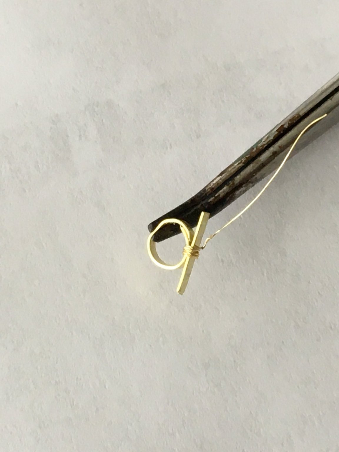
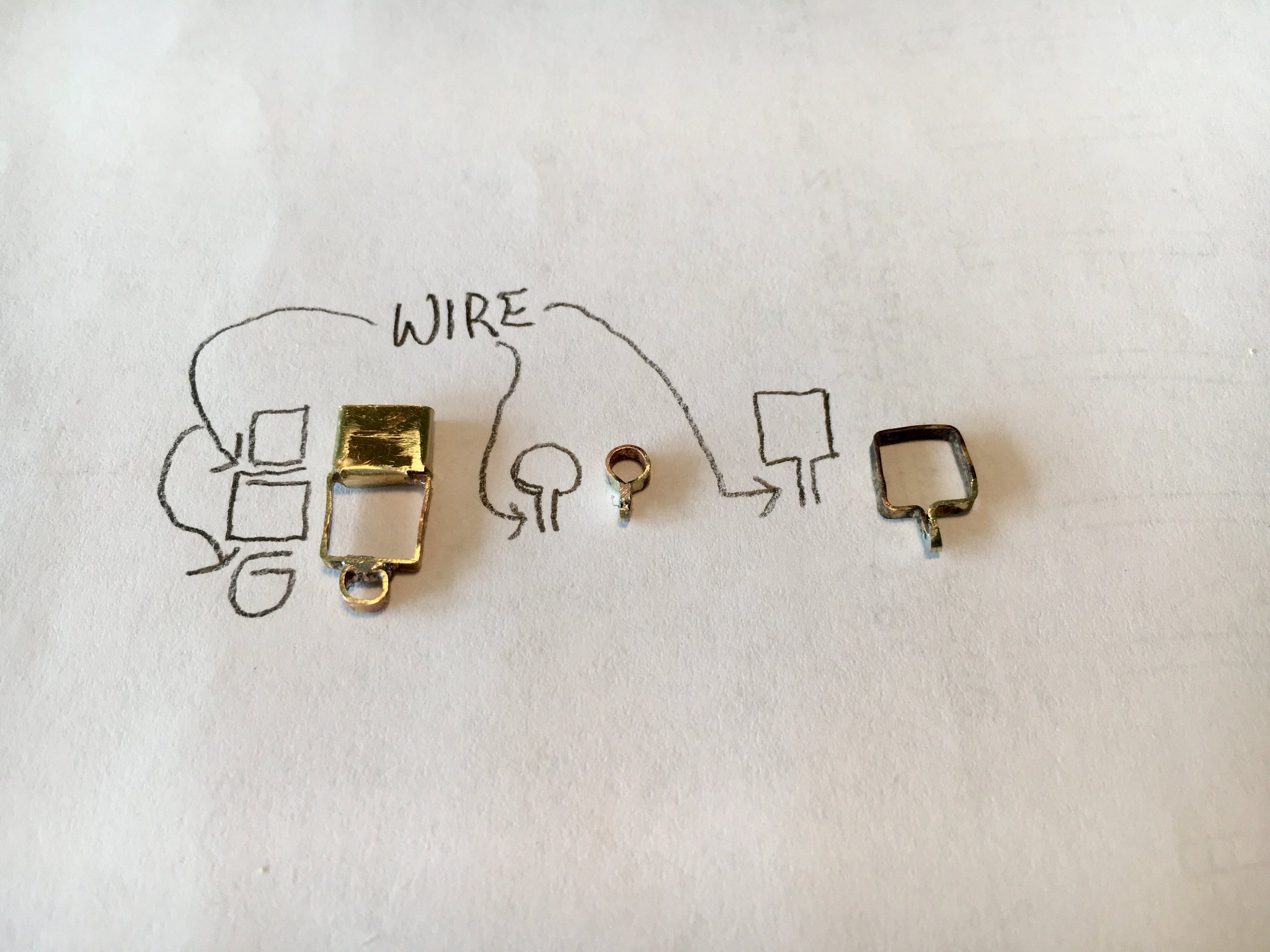
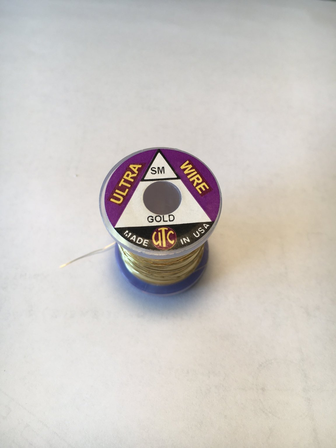
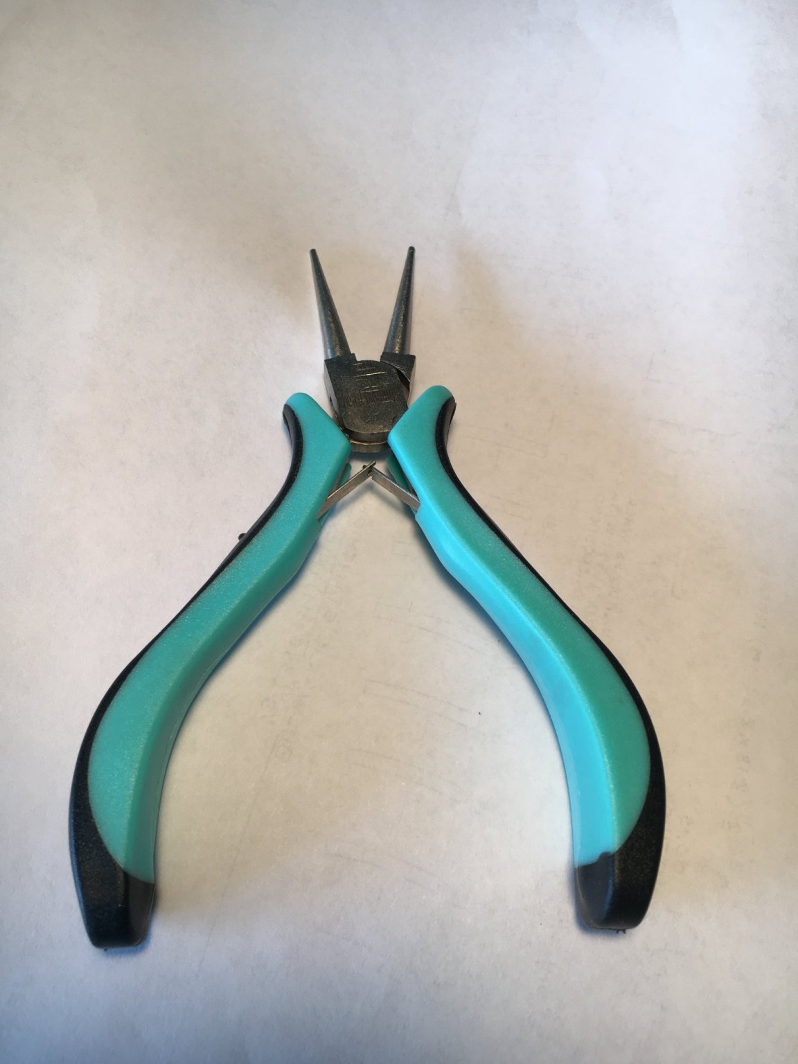
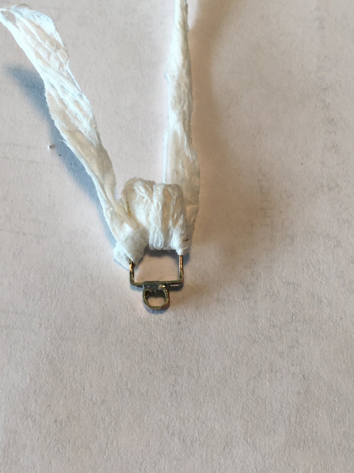
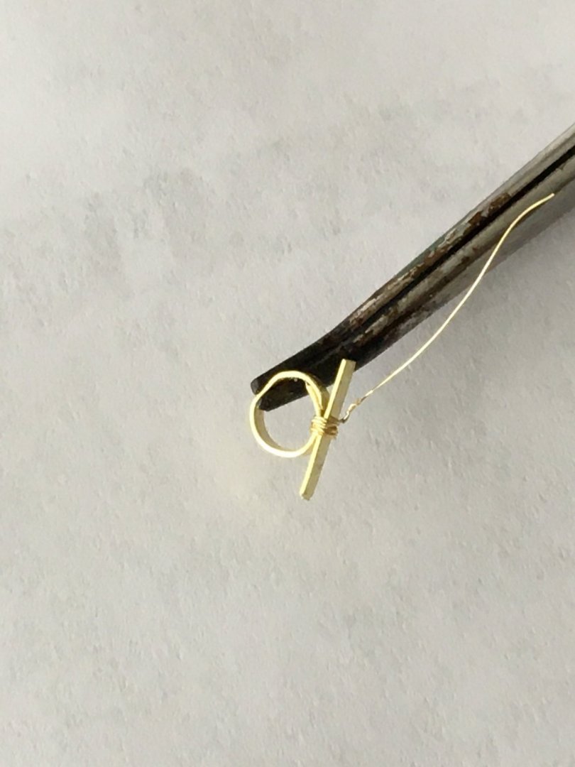
I turned my attention to making some of the fittings for the mast using the brass strips supplied with the kit. I would bend them to shape, clean and flux them and using a self-closing tweezer to hold the joint together as I soldered it. Alas, the tweezer acted as much as a heat sink as a clamping device and the result was poor joints. I tried a different approach that worked well for me. I took some fine wire I use for fly tying and then clamped the joint and wrapped it snugly using the wire, the tweezer can be removed after a few wraps. I then soldered the joint and after it cooled used files to smooth the area, I am happy with the result. The wire comes in different diameters and I used the smallest I had on hand. On one part there was an existing soldered joint so I wrapped it in a strip of paper towel then wet the tower to protect that join, worked fine. I also purchased an inexpensive pair of pliers with round jaws and they worked great to form curved parts, highly recommended. Looks like a bit more file work needed on some parts, amazing what you see when the part is magnified many times in the photos!


-
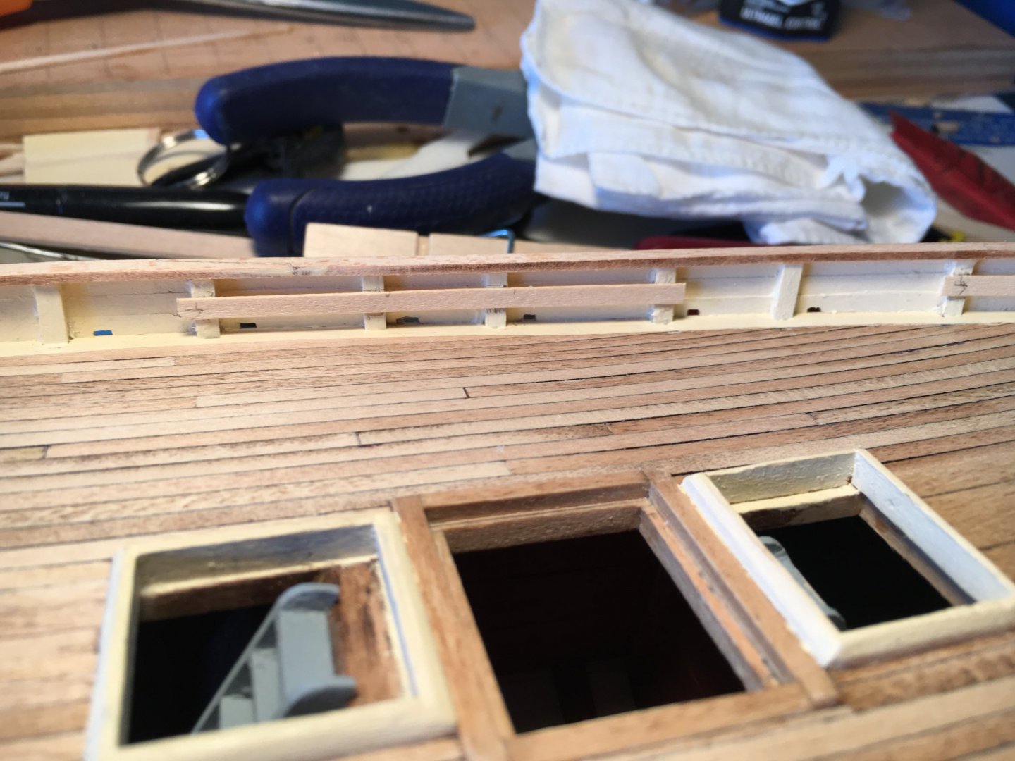
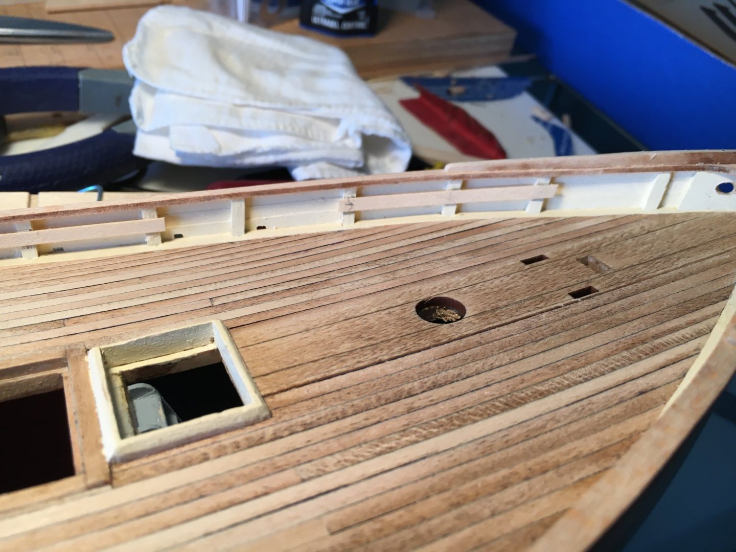
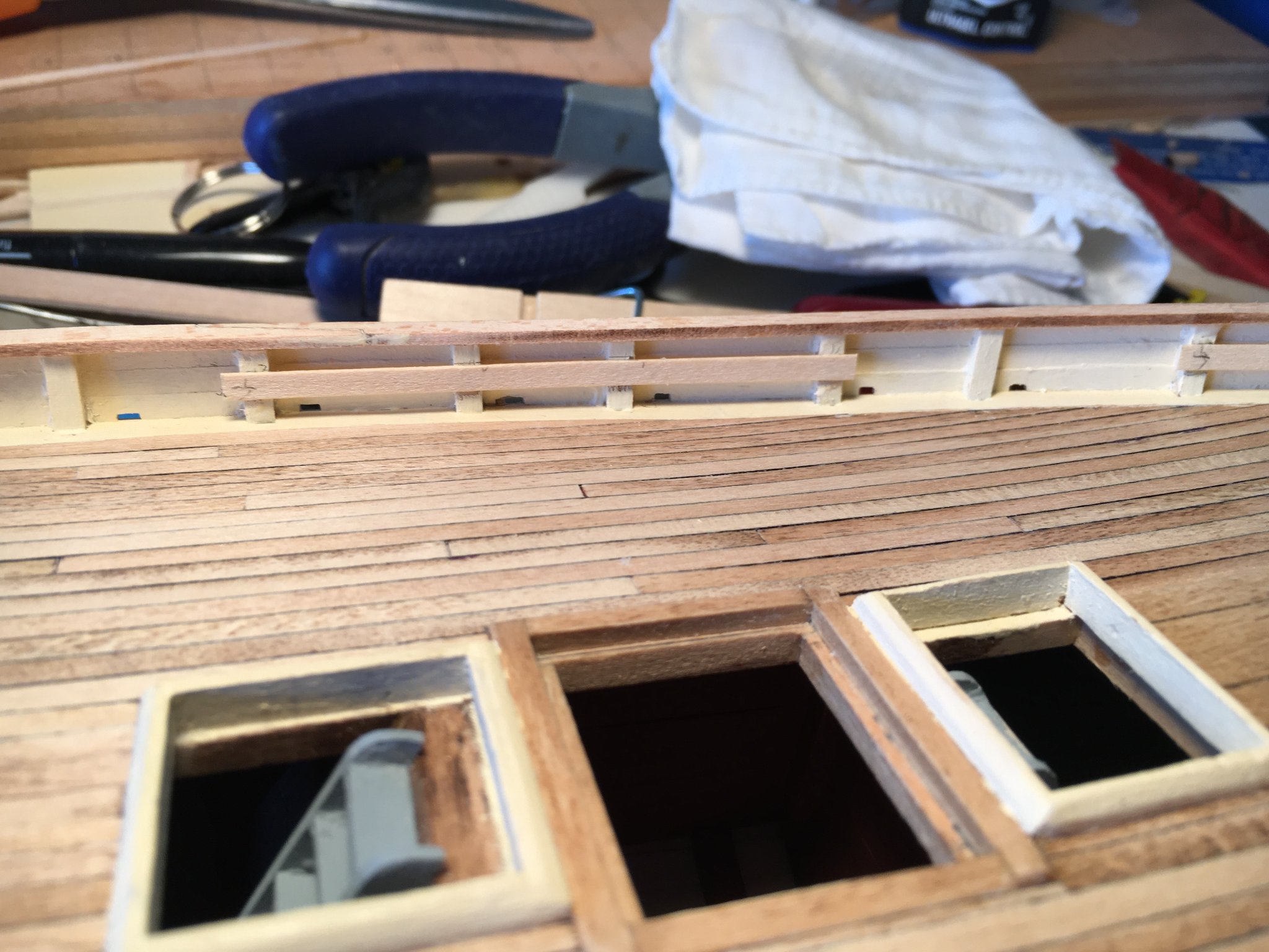
Looking very nice. I did not edge glue my deck planks but fastened then to the beams only and it sanded fine. I darkened the edges with permanent marker which I now do not recommend as some adhesive was pushed up between the planks and caused the marker to liquify and stain some of the tops of the planks, I was able to sand it out. I laid the planks in random fashion with no regularly repeating pattern and they look fine to me. There is a picture in my log. I installed the deck before the bulwarks as it allowed a bit more working room.
-
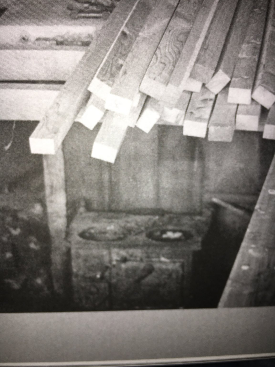
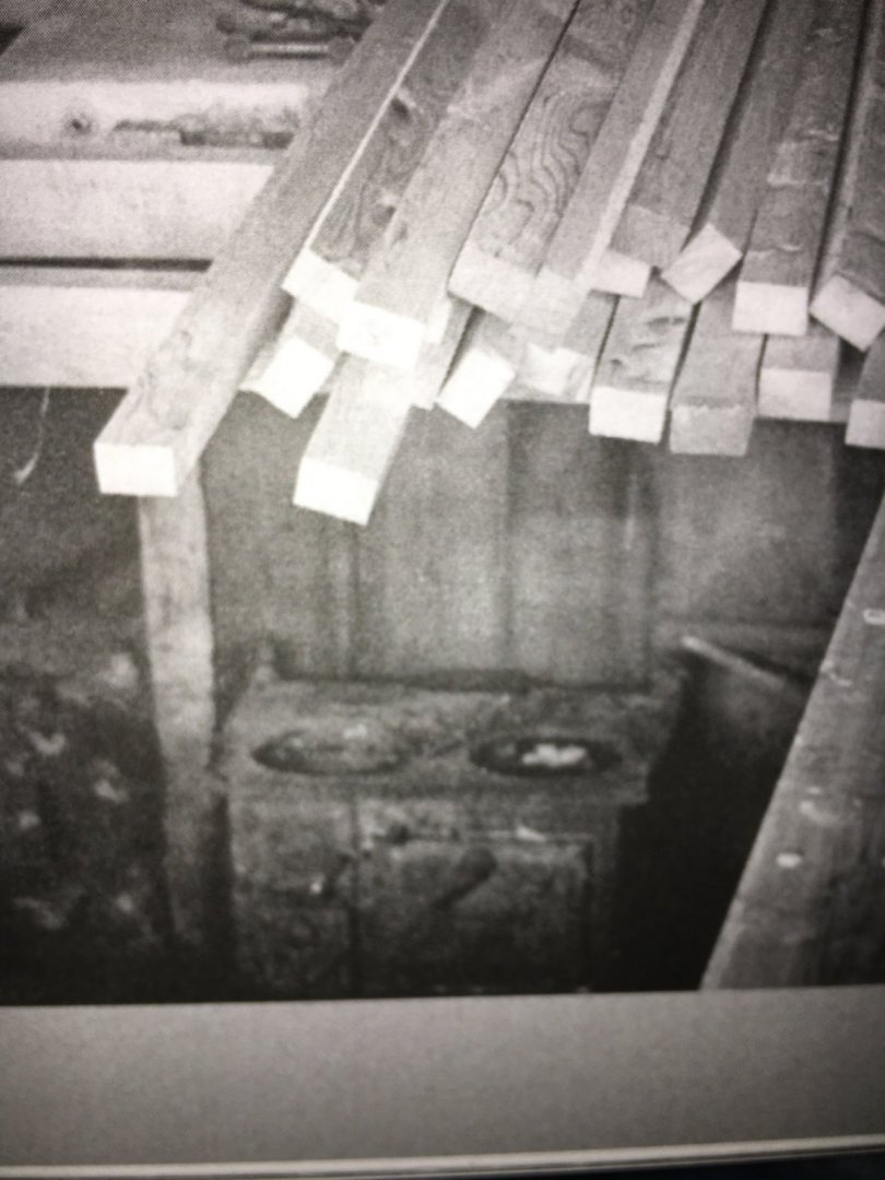
Will, I didn’t try to emulate any specific stove/heater. I just cobbled up something. I have a similar unit in my basement for heat but the top does get hot enough for cooking if needed. I have a cast iron kettle I place on top to produce steam for humidity when I use it. Here is a picture of the actual stove on the ECB, I didn’t try to replicate it. The photo is from the 1930’s so I have no idea if it was original when the boat was built. Here is a link to photos you may find useful. This was when she was rigged as a schooner but still some useful details. https://johnvanhornphoto.photoshelter.com/gallery/Emma-C-Berry/G0000TwT4ALJBw8s/ Another site http://02d243c.netsolhost.com/htdocs/vex4/E5D8A155-F149-414C-A48F-796948282462.htm
-
I'll try this one.
-
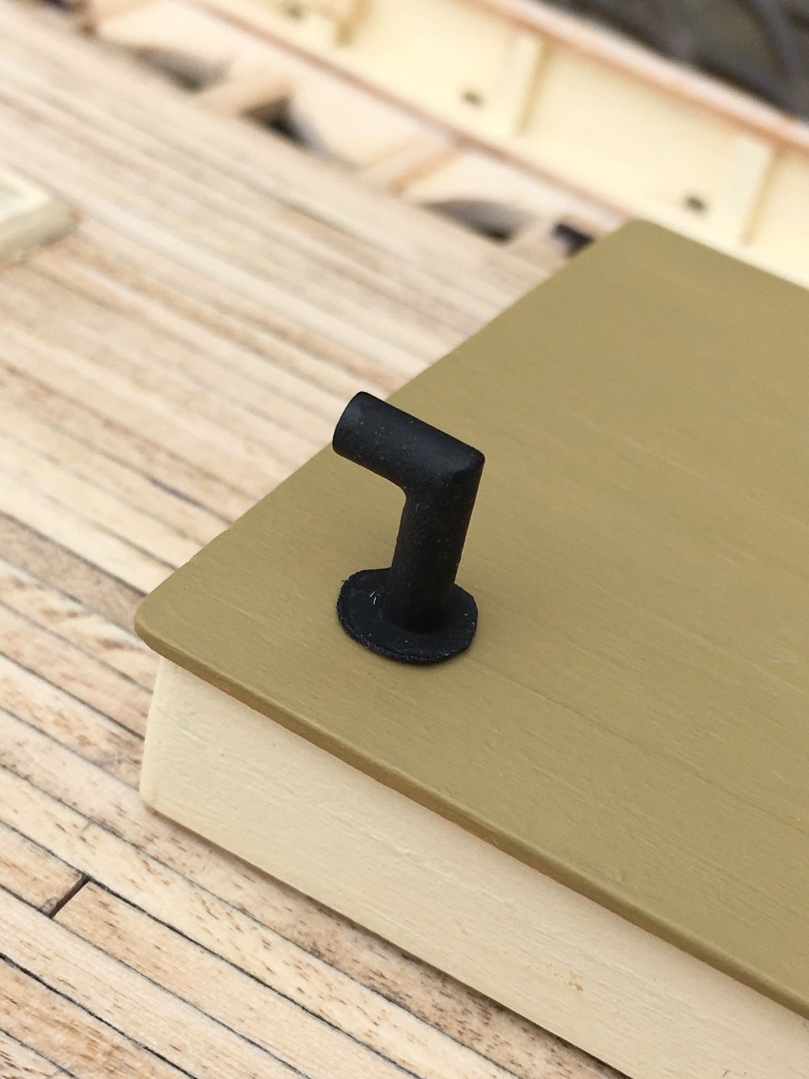
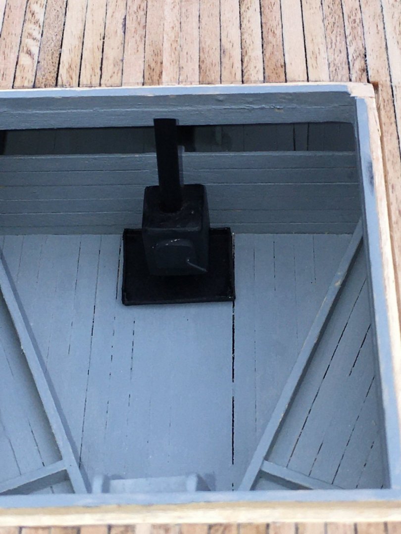
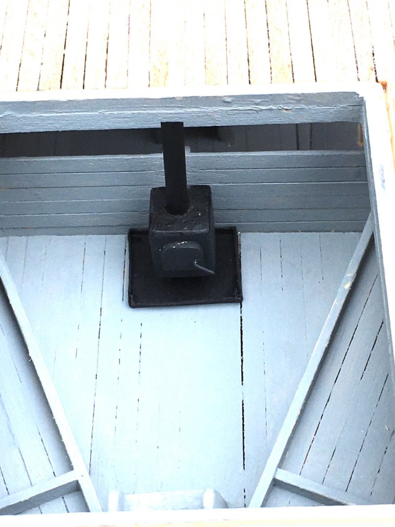
A bit more progress, any slower I would be going backwards! I made a chimney for the stove. I didn't much care for the look of the casting supplied by the kit so I used some Aluminium tube left over from a previous kit. I cut a 90 degree angle, used a bit of snug fitting wire and bent it to the same angle. I inserted it in both pieces of tubing to assist with gluing and joined them. I made the collar for the top of the cabin roof from paper. I also made a stove for the cabin out of scrap wood and made a pan for it out of paper. I put a small pin into the back of the stove and pushed the whole thing into the bulkhead to keep it in place, totally hidden from sight.. Happy with both efforts.

-
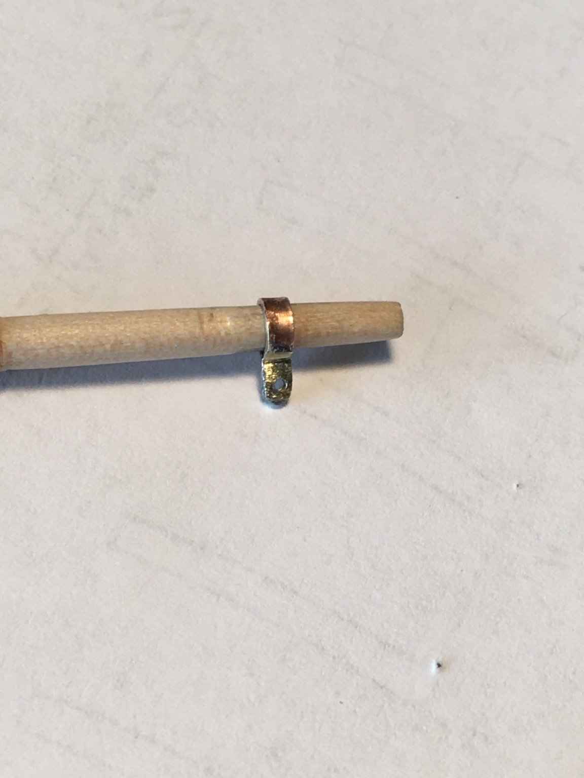
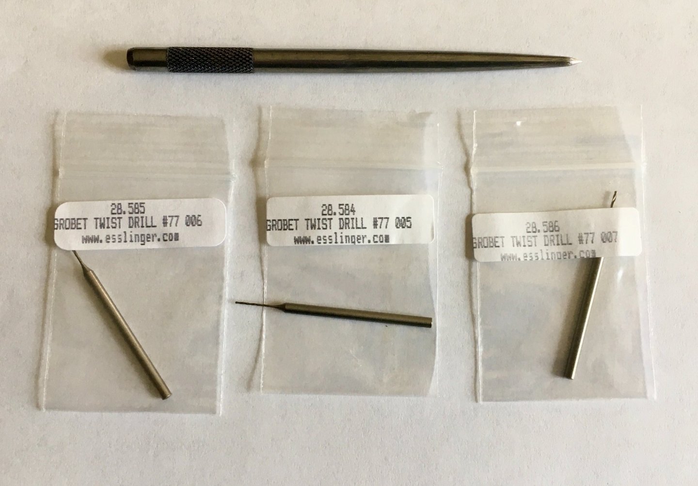
Will, a review of the drill bits I received: I am extremely pleased with them! I ordered them on Saturday, they shipped Monday and I received them Wednesday. I tried one today and what was a 10 minute finger numbing trial with my bargain basement bits turned into a pleasurable 1 minute chore using my pin vice and new bit. I replicated my previous experience on a piece of flattened copper wire. There is a bewildering selection of bits on the site so I took a shot in the dark and ordered these. I liked the 3/32" shaft as they will work in my pin vice or Dremel tool, they worked so well in my vice I will probably not use them in the Dremel as it would seem easier to snap them. I have no experience as to their longevity so time will tell that tale. I also ordered a fine center punch and that worked well to prevent wandering. Here is a link to the site and the bits I ordered. Not outrageously priced and quick shipping. https://www.esslinger.com/tungsten-vanadium-steel-drills-twist-diameter-0-50-2-30-mm-drill-bits-each/ I also did file work and painting on the shackles and am fair pleased with the result.
-
Making slow progress, better than none I reckon.
- 101 replies
-
- 1
-

-
- emma c berry
- model shipways
- (and 1 more)
-
The build is looking great!
-
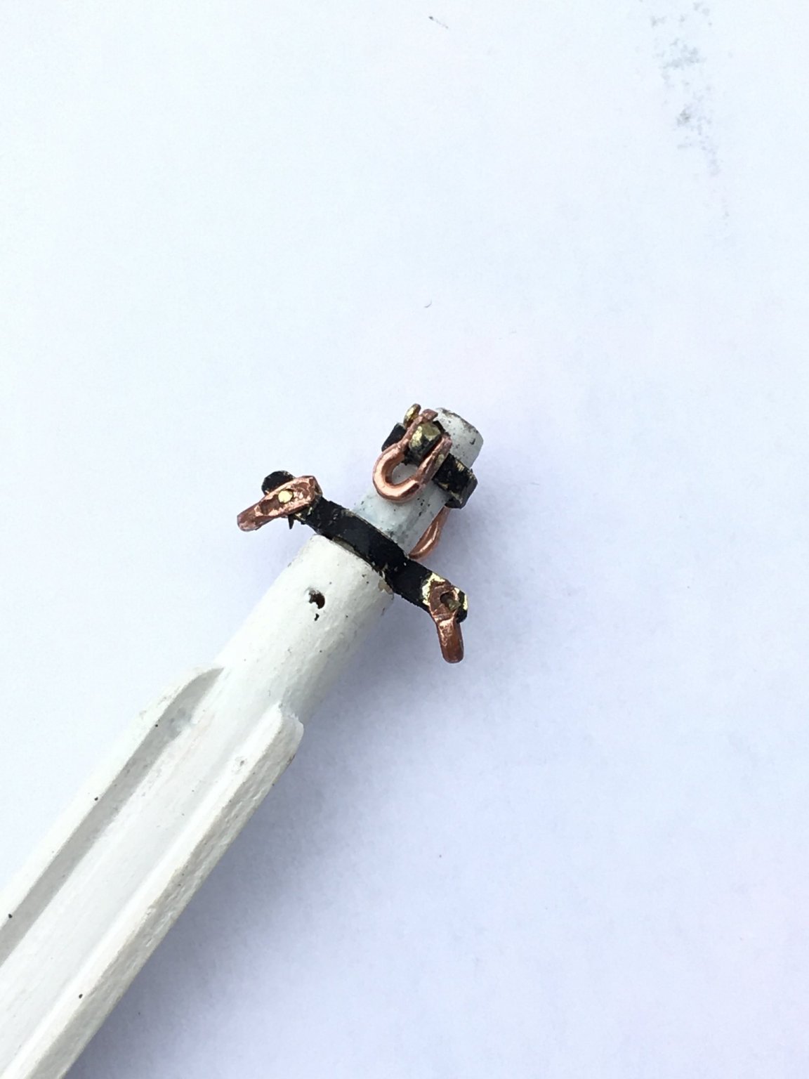
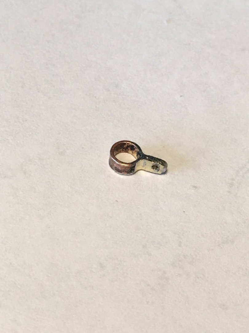
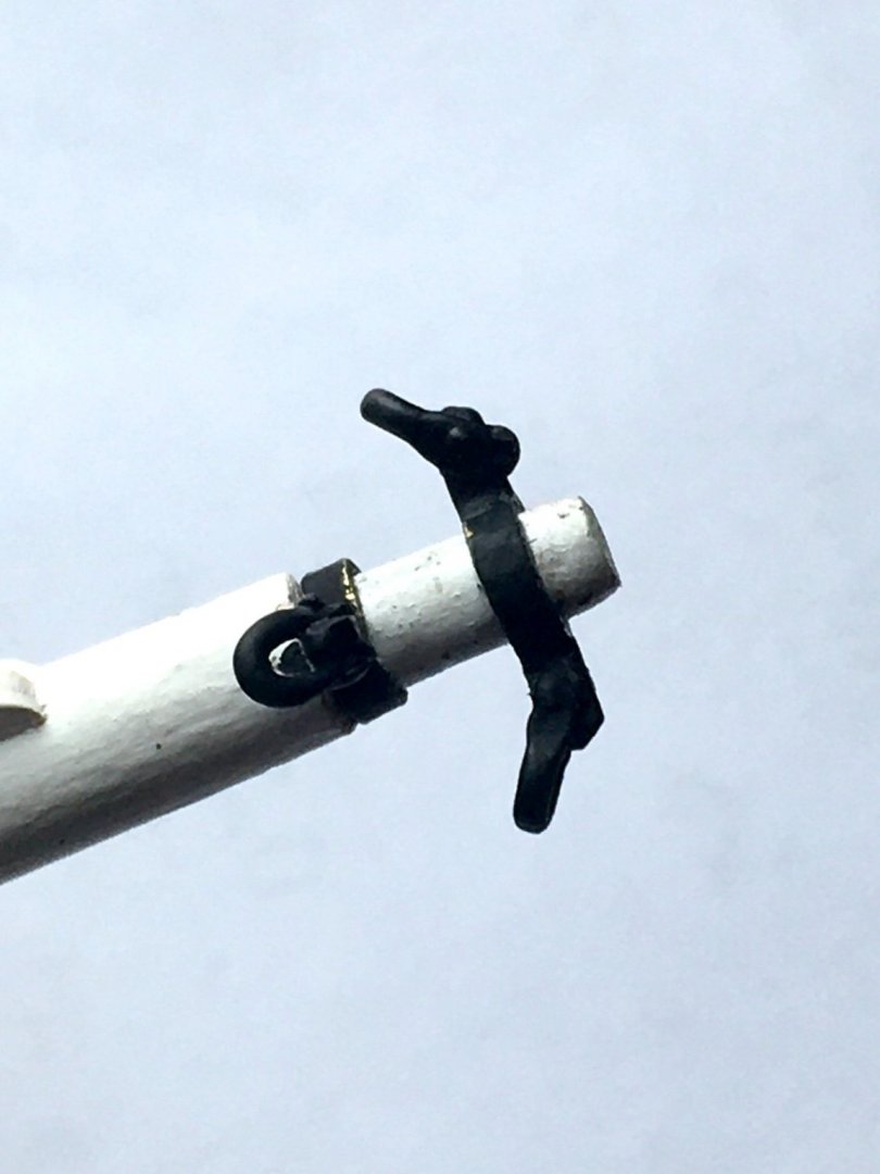
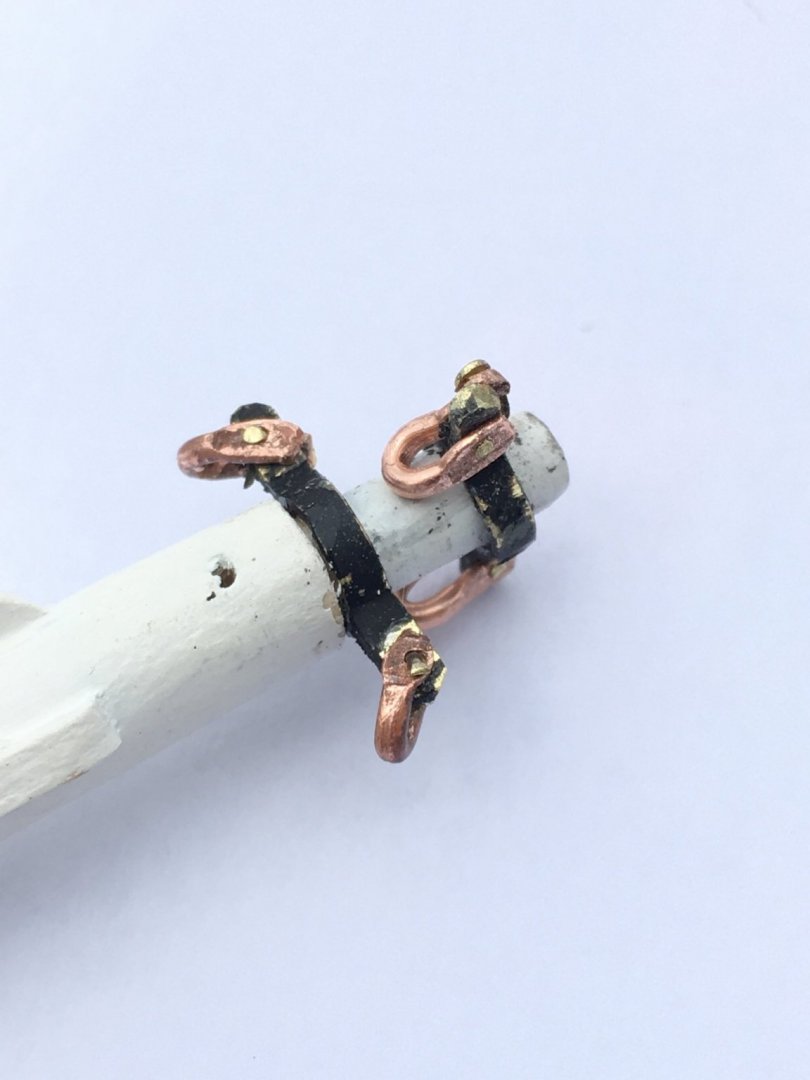
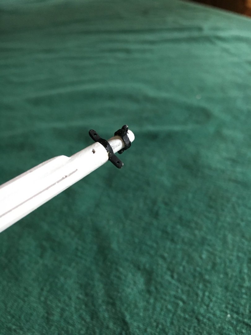
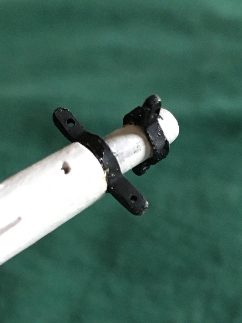
mek, Thanks for the great advice! I actually made some shackles before reading your post but will try your method for more I have to make. I used 18ga copper wire as it is easier to work than brass, flattened the ends with pliers, drilled the holes and bent them to shape. I used a tiny brass nail to connect them to the bands and attempted to peen one end to secure the pin with limited success, even the tiny pins are hard to peen successfully despite trying to anneal them with heat, any suggestions welcome. I was concerned that glue would not secure them due to the small gluing surface. They are installed but need some file work and painting. Not surprisingly the camera is not kind with close-up photos but I think they will look fine at a scale viewing distance.

-
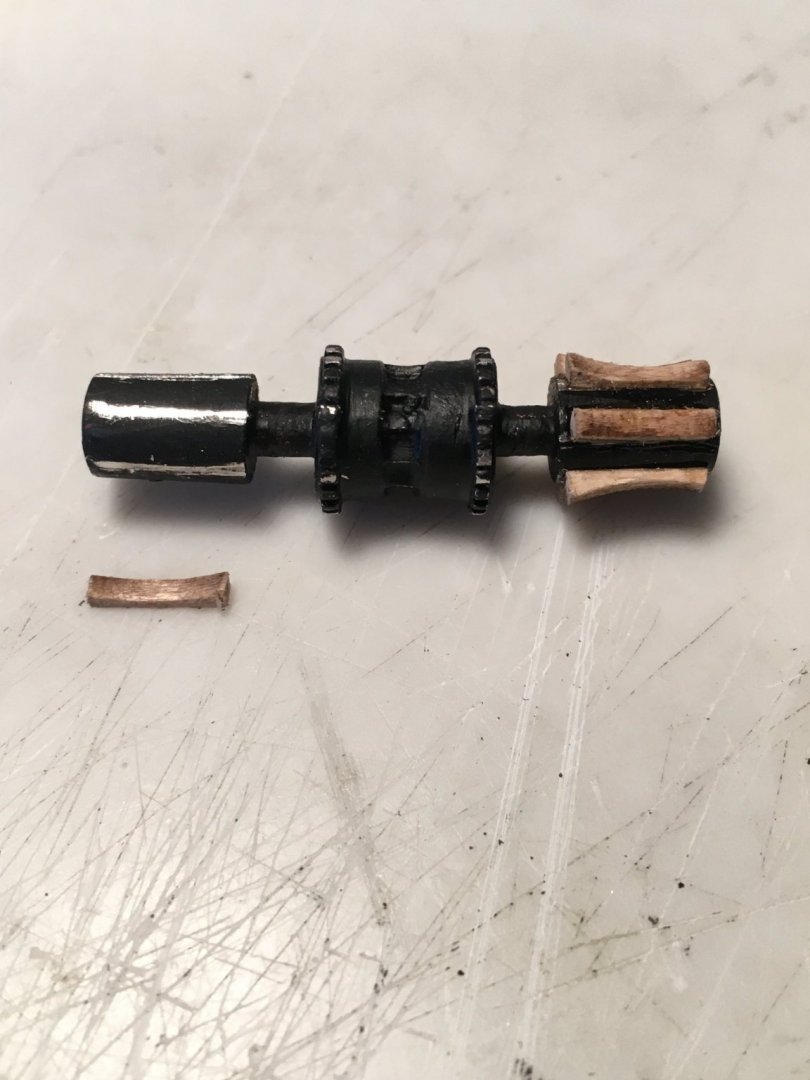
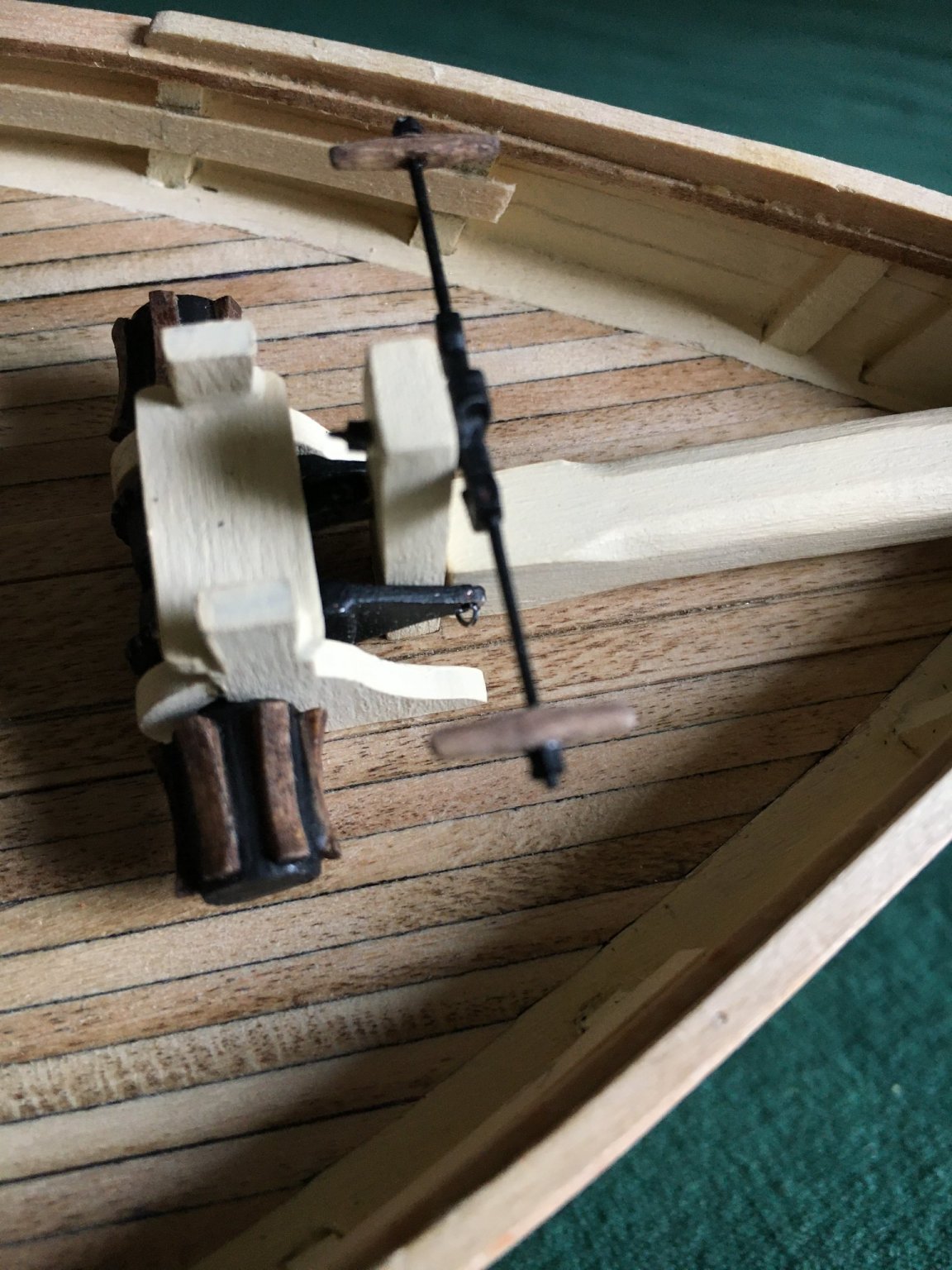
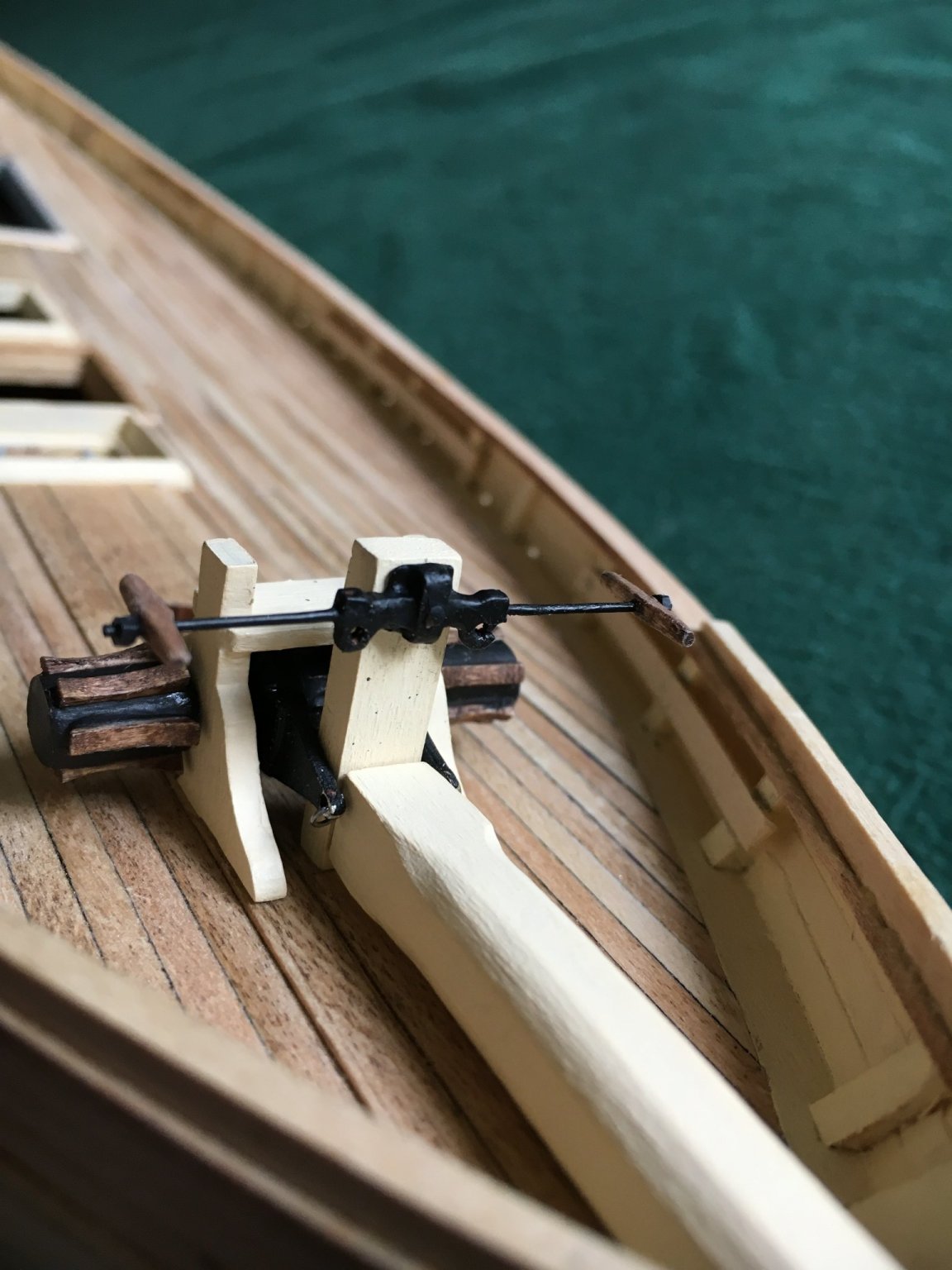
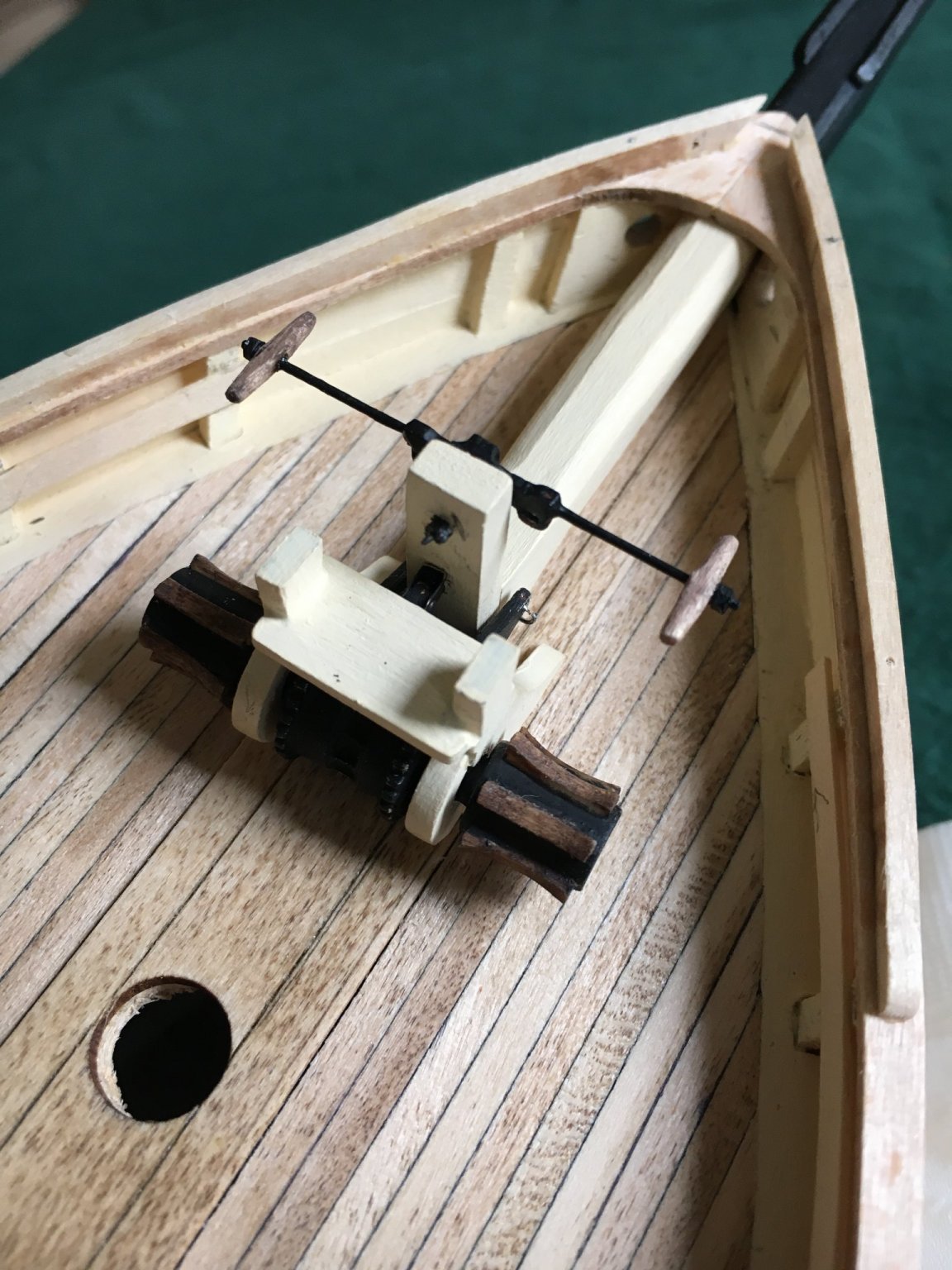
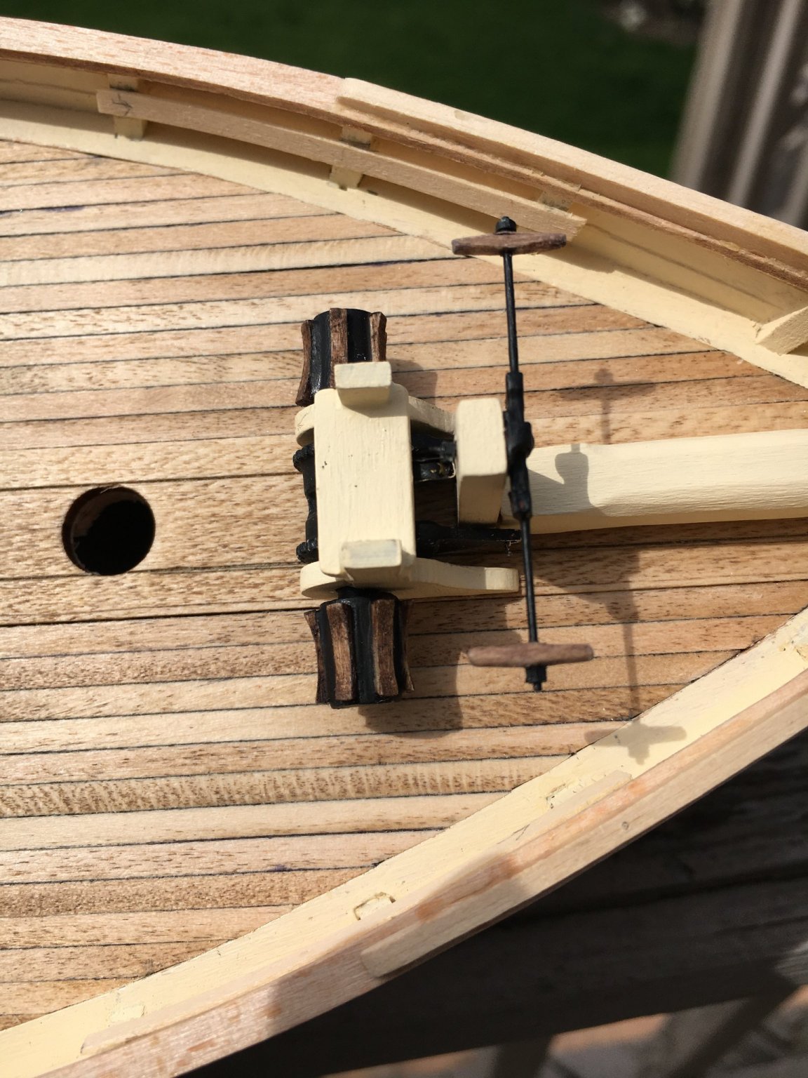
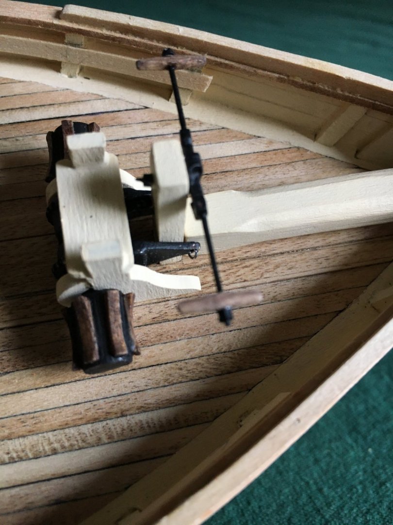
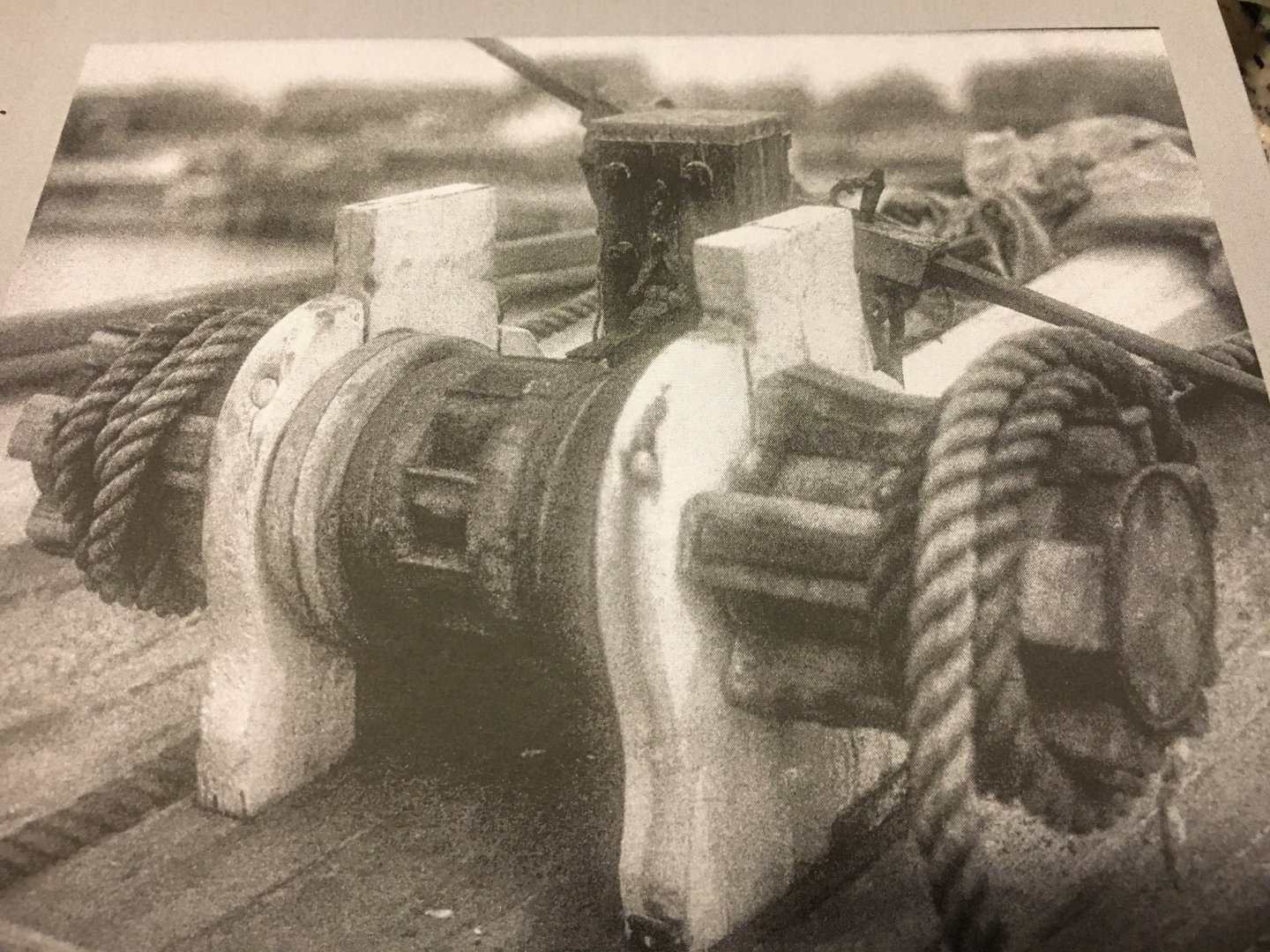
Time for an update: I have been spending time working on the fiddly bits and machinery. I installed the windless in it's frame and attached the brakes, I then turned my attention to the brake mechanism on the post. The plans and instructions seemed to contradict each other one calling for wood arms and the other for a rectangular brass arm. I found a photo of the winch that appeared to show steel arms so I went that route as the other options would have been a challenge to connect, probably not period correct but the model is not destined for a museum or juried competition. I used a piece of sewing pin, drilled a hole in the boss and used the pin as an arm. I made wood handles for the ends and used some plastic hex shaped rod to simulate nuts on the ends of the rod. I attached the entire mechanism to the post with a pin and CA glue and again made a nut from the plastic rod. The entire mechanisms are temporarily in place and I still need to make the connecting links on the windlass brakes and the post apparatus when I finally install them, I am setting everything aside until I paint the hull for fear of breaking them during that process. I next worked on the bowsprit iron bands. I used the brass strips included with the kit, bent them to a half circle shape over an appropriately sized drill bit and left some material perpendicular to the bend. I prepared and fluxed that material, clamped two pieces together and soldered them to form a band. I then trimmed and filed them to shape. Drilling the holes was a nightmare due to my cheap drill bits, after several broken bits and cussing like a sailor (certainly appropriate for a ship model in retrospect) the deed was done. Not perfect but satisfactory to me. I have ordered some new bits from a watchmaker supply house and will report if they work better. Next I need to make shackles to attach the rigging, a head scratcher at best and any advice would be very welcome!!!

-
Looking good! I second the opinions for using yellow glue, works much better, Titebond is a brand that has worked well for me. As for excess cleanup, I have found that if you let the excess start to setup and get a bit rubbery it is easy to cut that excess away with a sharp knife.
- 85 replies
-
- 2
-
-
- Lowell Grand Banks Dory
- First Build
- (and 2 more)
-
As a relative newcomer myself don't try to build a museum quality masterpiece first time out, do the best work you can and it will be a great learning experience! Enjoy your progress and ask any and all questions, I have received great advice and help from experienced members here. As to sanding, druxey gave great advice, I have found that a flat piece of sandpaper will lie fine on a flat surface without rubber cement although it will certainly help! Another thing I have found is that when sanding a long surface like the planks in your photo I unintentionally tend to apply a bit more pressure to one end so I reverse them during the process to try and get both ends level. Good luck, I look forward to following your build!
- 85 replies
-
- 4
-
-
- Lowell Grand Banks Dory
- First Build
- (and 2 more)
-
Another vote for Renaissance Wax. Apply it it to rope and draw the rope through the fingers to create a bit of friction. I have also used it for years on wood, metal, paper and cardboard also with no ill effects. It is a favorite of museum conservators due to it's neutral PH and longevity. A bit expensive but a small container will probably last a lifetime. https://www.talasonline.com/Renaissance-Wax
-
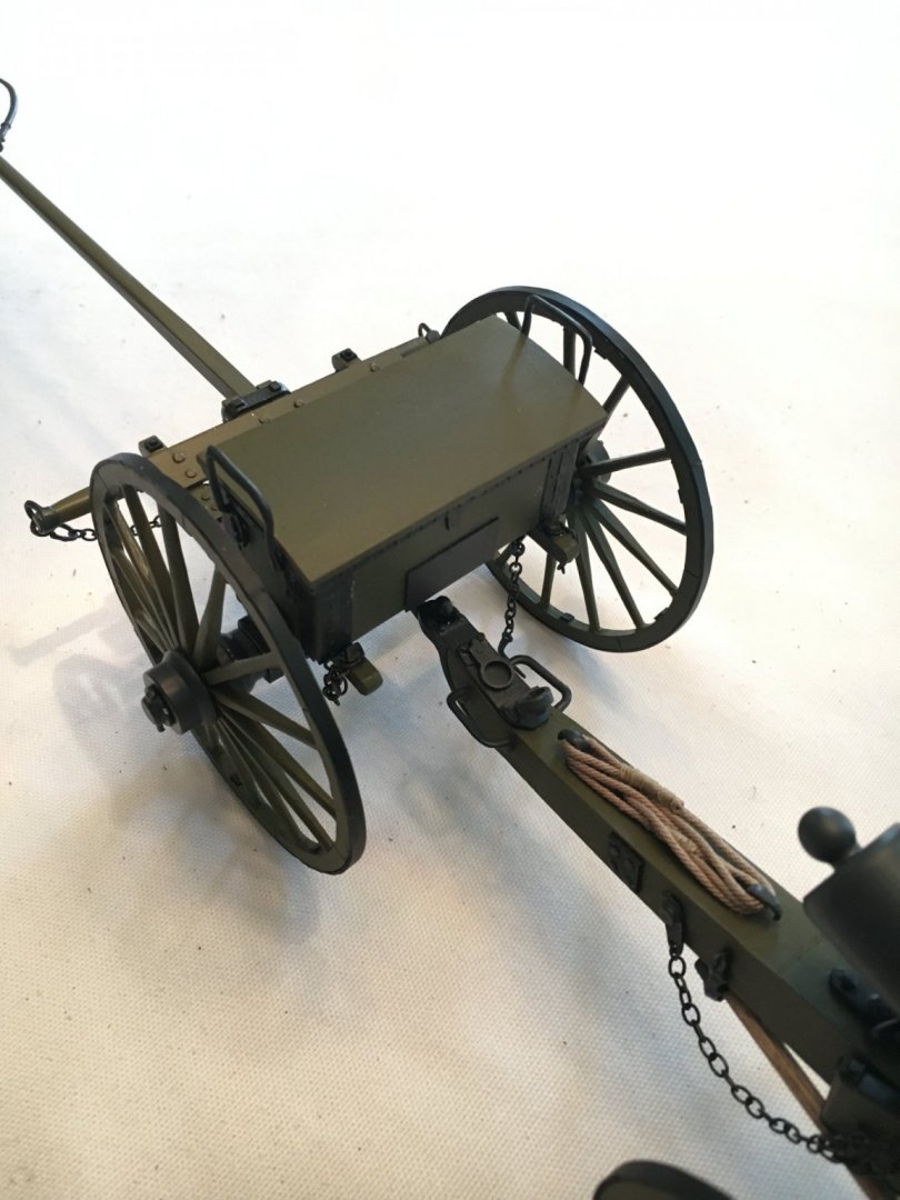
G. Delacroix, thanks for your input! I reviewed the instructions and believe I have installed the wheels backwards!☹️ I will attempt to correct that, you have a very sharp eye. MS4000_Cannon_Wheel_construction_method.pdf
-
Thanks! I could probably still reverse them. You are exactly right!! As I mentioned instruction were a bit lacking. I should have done some research.
-
Sea Hoss, I cut the rudder post in order to be able to insert the rudder from from the bottom, much easier to adhere and paint the rudder to the post while not in place. If anyone tried to move the rudder with the tiller it would immediately break the handle. I left enough of the post above the rudder to allow it to be easily inserted into the hull and the cut not visible.
-
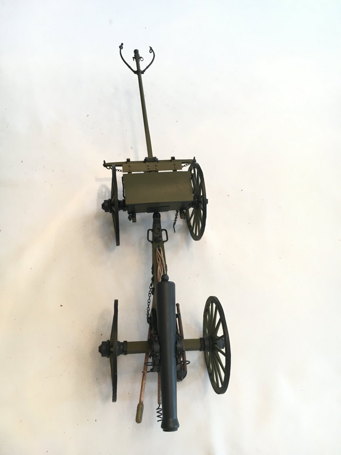
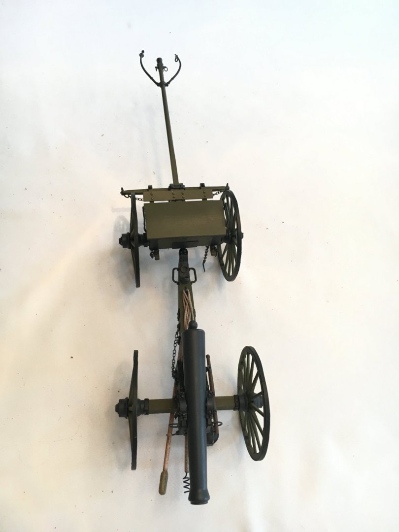
Beautiful Job! As a retired 35 year Firefighter we used to call that brand of apparatus American Take a Chance.
-
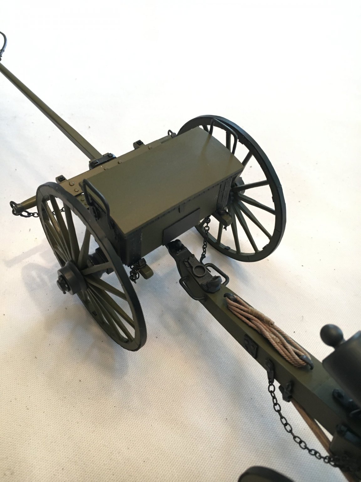
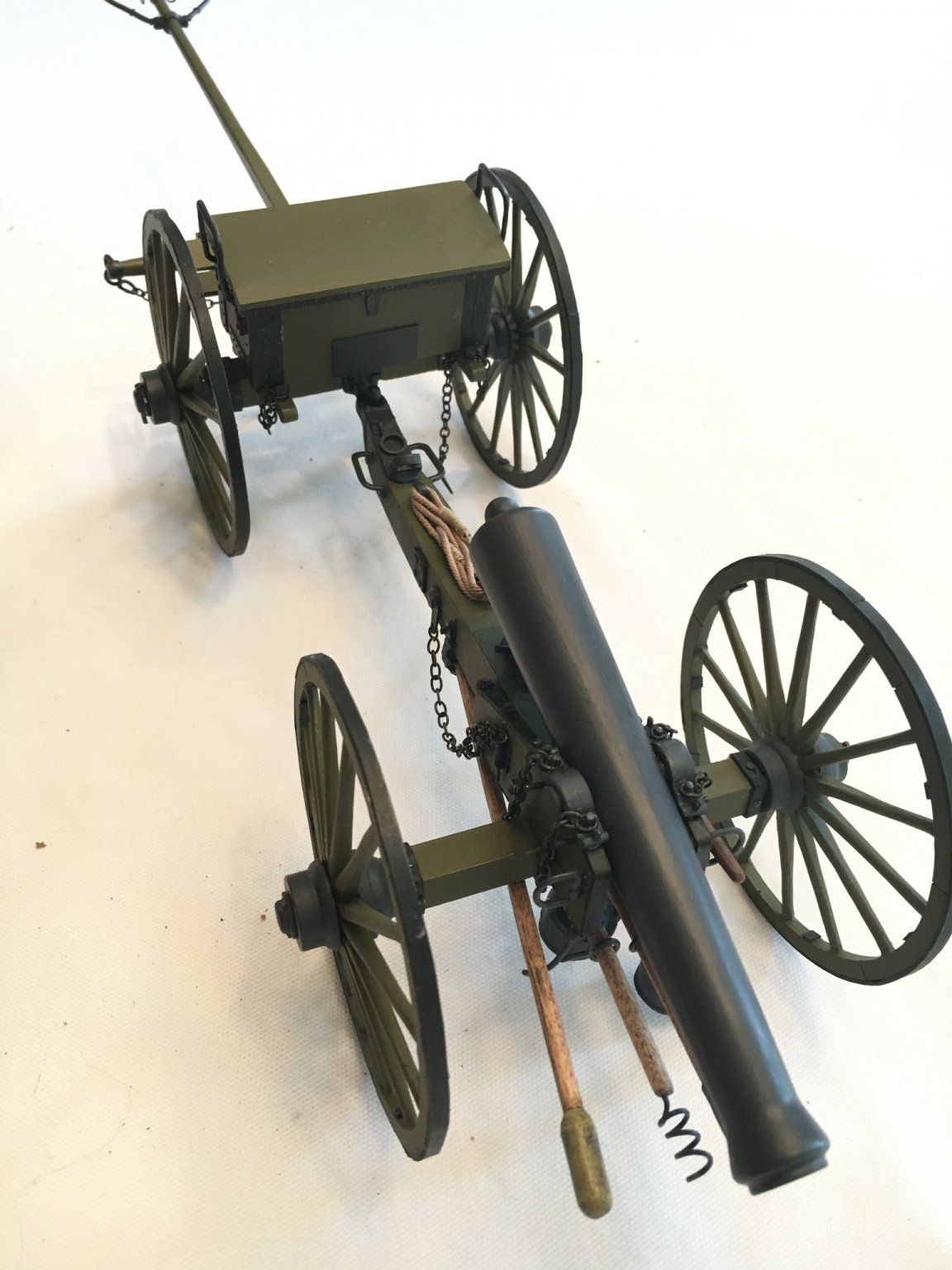
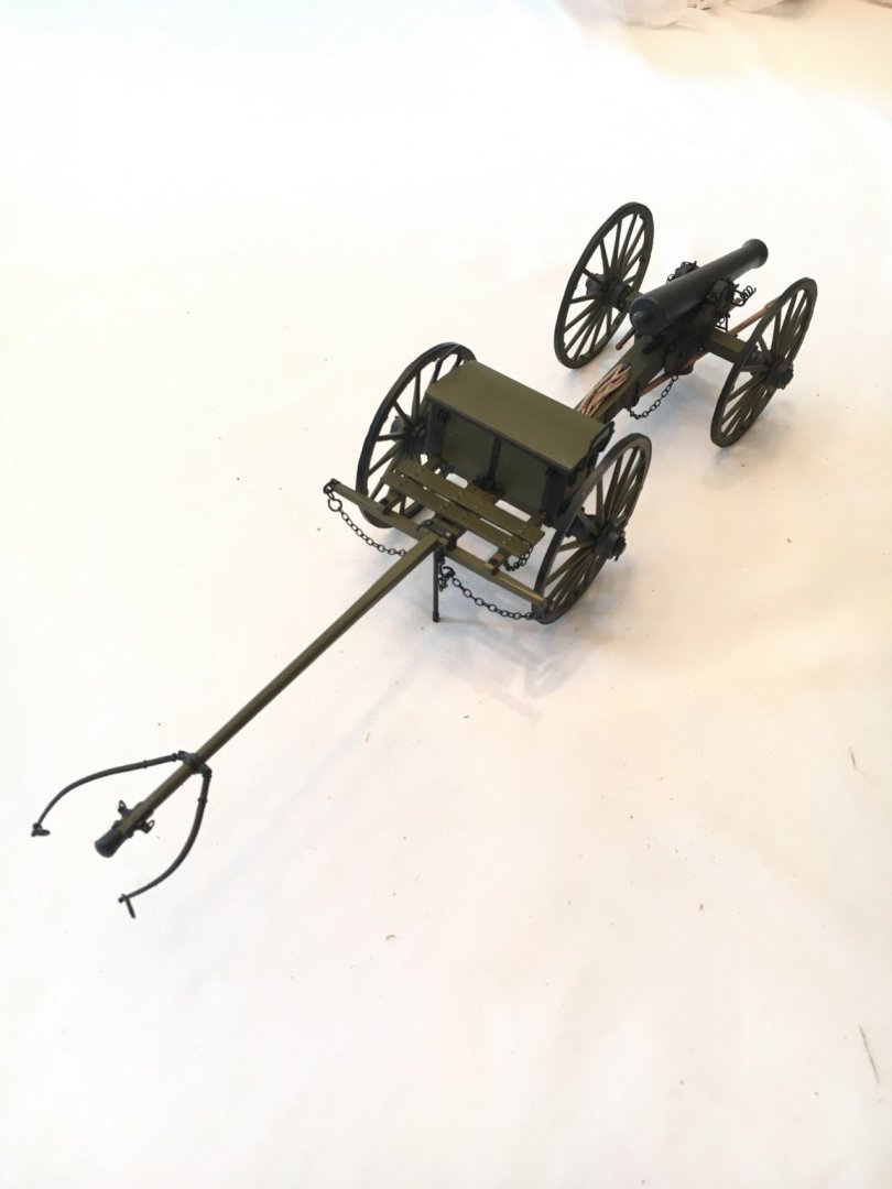
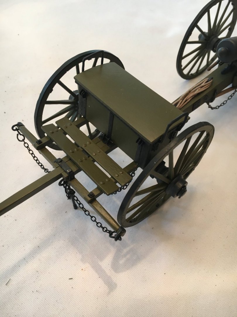
A few months ago I took a break from ship modeling and spied the Napoleon Cannon and Limber kit on sale at Model Expo for about 1/2 price. I decided to give it a try and thoroughly enjoyed it! The large scale made it easier than many ship models. The parts and material supplied were typical of Model Shipways, wood good, castings fair the biggest surprise was the instructions were mediocre at best. I muddled through and was pleased with the result. One of the most tedious but enjoyable tasks was building the wheels. A template and building fixture was included and each wood spoke had to be shaped and attached to the wood rim and metal hub. The attachment at the hub was rather weak and I devised a solution. After the spokes were attached at the hub I wrapped the spoke-hub area with thread, secured with a couple of half-hitches like my fly tying and soaked it with thin CA, incredibly strong. The barrel is a hefty piece of turned brass and well done. I failed at trying to chemically blacken it so painted it. If you see it on sale give it a go. They do sell a cast wheel version so be sure you buy the wood spoke wheel version if you are so inclined.

- 5 replies
-
- 14
-
-
Thanks Will! Epoxy seemed the strongest option that would give me time to adjust position.
-
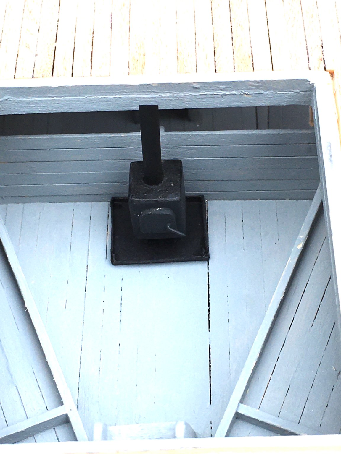
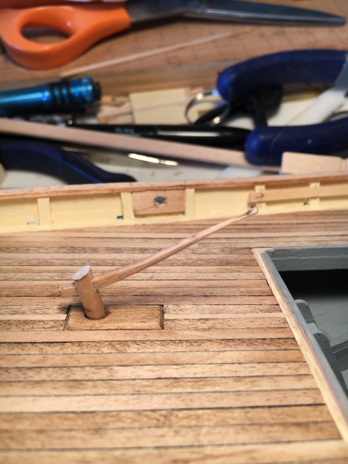
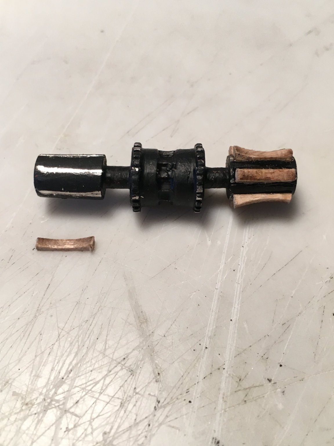
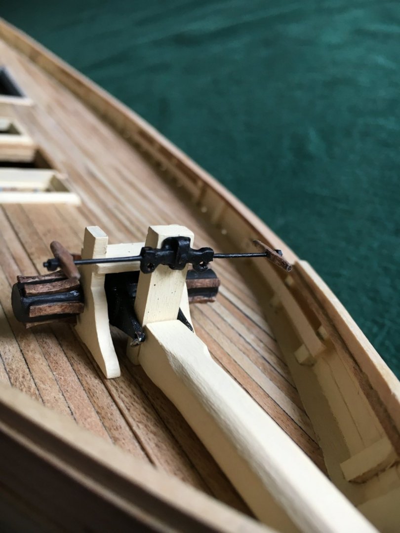
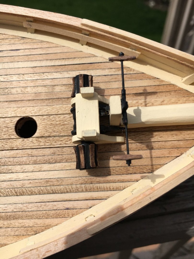
A bit more progress to report. I installed the lashing rails. It was very straight forward but I still need to paint them. I turned my attention next to the tiller. The tiller handle itself is very delicate and I used utmost care shaping it lest I damage it. I am happy with result, in the photo it is temporarily in position as the post still requires painting. Next I worked on the winch. I painted the metal part and let it dry. I worked on the whelps to get a proper gluing surface on their bottoms. I then used a small file to get down to bare metal on the landing surface after careful measuring of the layout. I mixed up some 5 minute epoxy, spread it fairly thin on the mixing card and dipped the bottom of the whelp in it and placed it in position on the metal winch. The epoxy gave me a bit of time to nudge the whelp into position and I think it turned out well. I did 2 whelps at a time.