HOLIDAY DONATION DRIVE - SUPPORT MSW - DO YOUR PART TO KEEP THIS GREAT FORUM GOING!
×


turangi
-
Posts
276 -
Joined
-
Last visited
Content Type
Profiles
Forums
Gallery
Events
Everything posted by turangi
-
 Looking very nice! I will be following your progress as I am working on the same model now.
 -
Removing Laser Burn?
turangi replied to Shaft's topic in Building, Framing, Planking and plating a ships hull and deck
I found that scraping it with a hobby knife or cabinet scraper has worked well for me. If it is a part to be glued after scraping pulling a fine razor saw blade pulled perpendicular to the surface creates fine grooves and seems to promote better adhesion,120 grit sand paper also does a good job I have never encountered any problem with painting as long as most of the char is removed. One thing I have noticed is that the laser cut edge is usually not square and and a bit of scraping or sanding may be needed to correct this. Post #2 in this thread discusses that issue. -
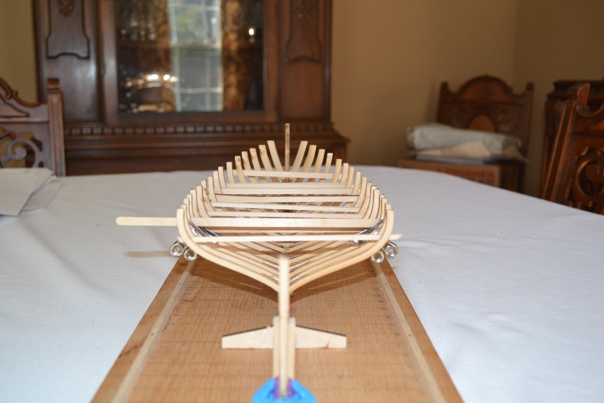
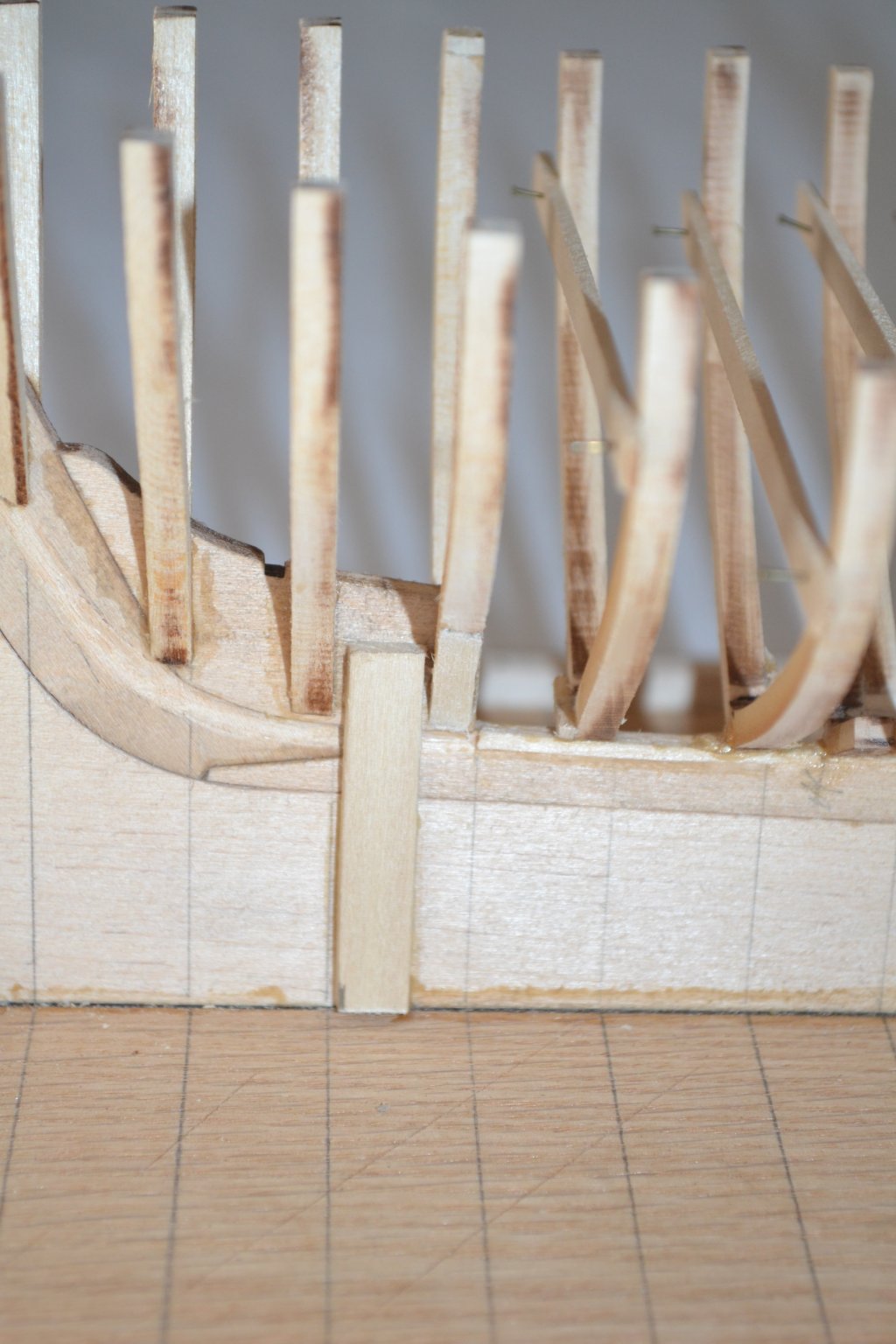
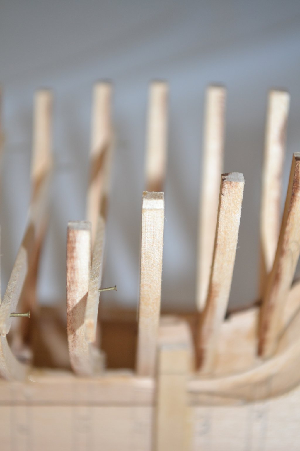
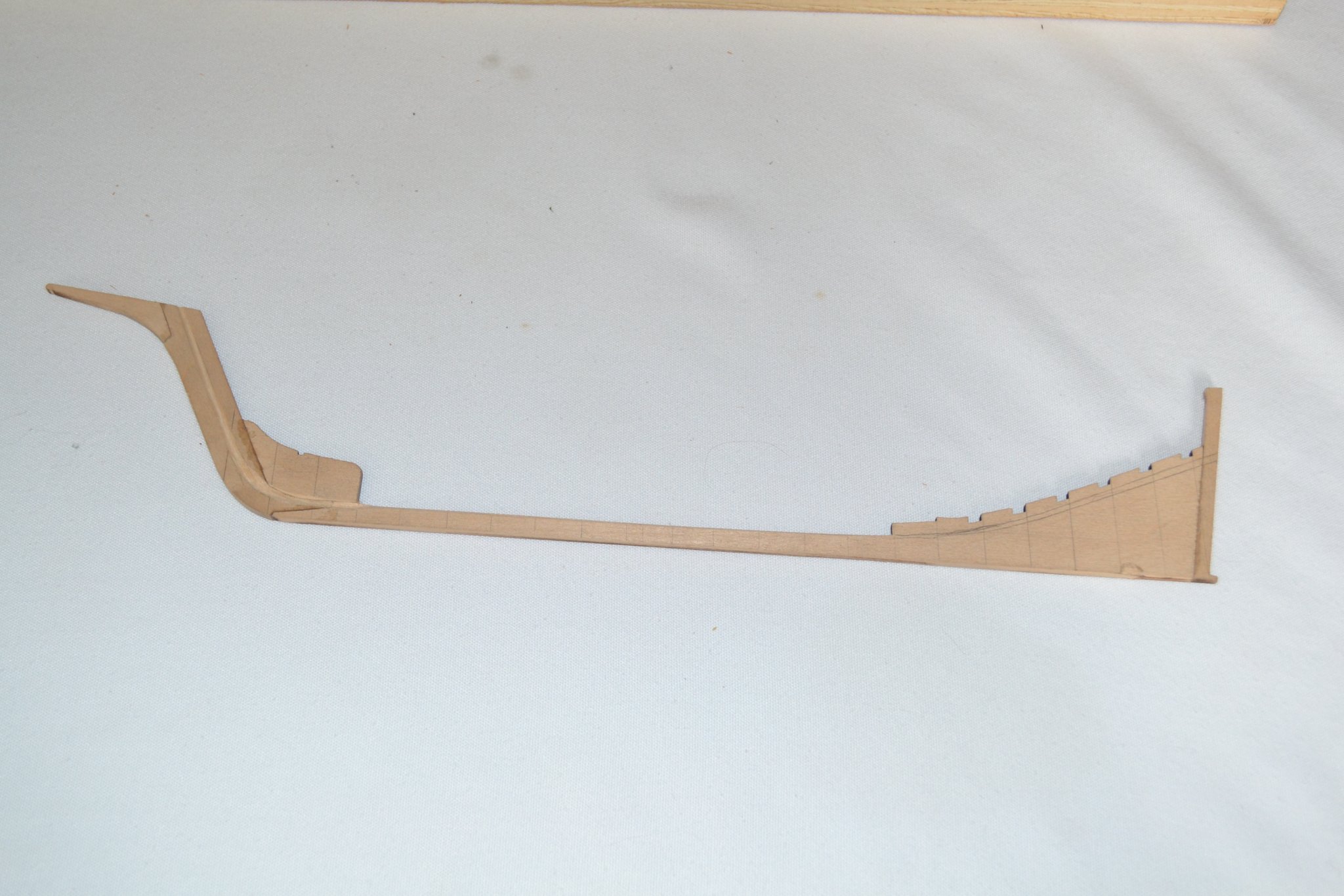
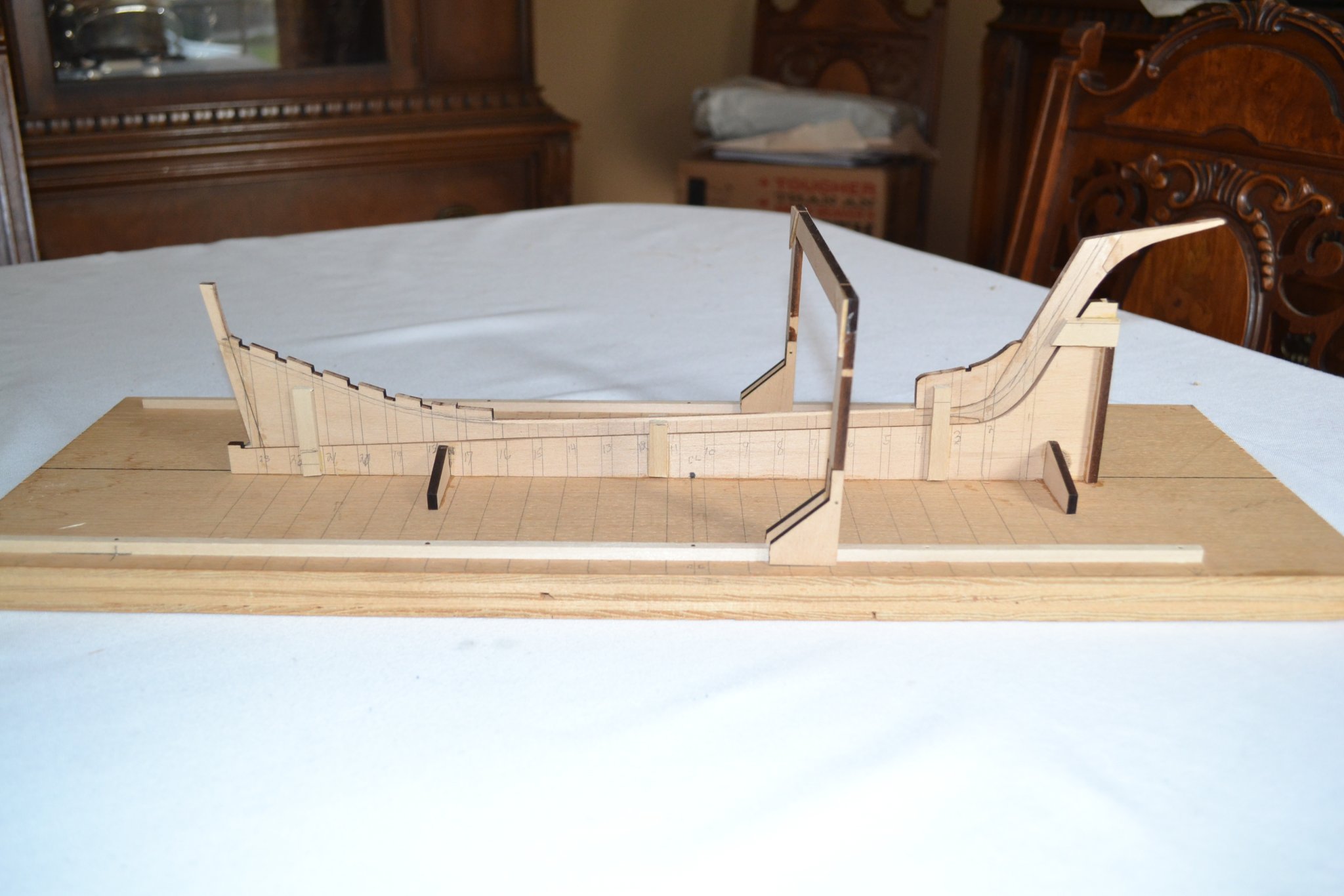
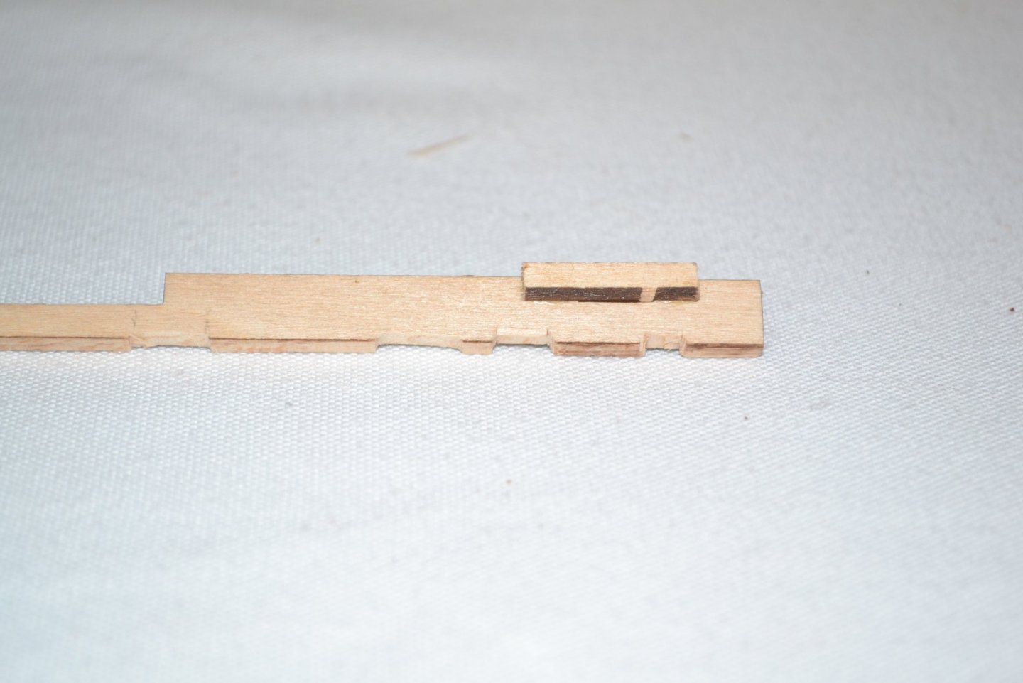
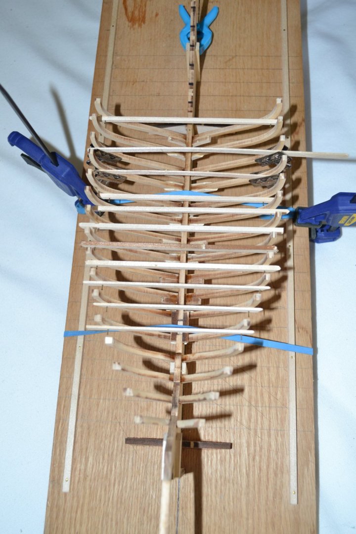
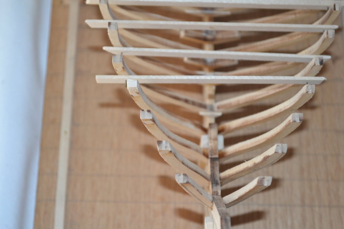
Time for an update on my snail's pace progress. I complete installing all the frames up to the point that the keelson attaches going up to the stern and thought it a good time to install the keelson. I checked all the frames prior to installing the keelson and found one seriously out of alignment, it was the one frame I experimented driving a brass pin through the frame and into the keel as I was rather concerned with the tenuous connection between the frame halves and the keel. The pin wandered off path and pulled the frame seriously out of alignment. I managed to remove and reset the frame without serious damage. I still suspect some shimming may be in my future for other areas. I test fitted the keelson and it was like a rocking horse, no doubt to my my improper sanding rather than a design defect. All frames were set to the proper height per the plans but the error was due to my improper finishing of the landing area for the keelson. At that point modifying the landing area on the frames was near impossible so I modified the keelson as seen in the photos by removing material as needed. I established the correct attachment level fore and aft for the the keelson and removed material as needed on the keelson to ensure a tight fit on the frames, seemed to work well. I used one hour setting epoxy to attach the keelson as I had no doubt I could not work fast enough using the 5 minute variety. I applied the adhesive to each frame/keelson juncture and also to the forward end of the keelson and used a brass pin at the aft end to secure it in addition to the epoxy. I used rubber bands in the middle to apply pressure. This was my first time using 1 hour epoxy and I was sure I had mixed it improperly while waiting for it to cure, I put it out in the hot sun and it cured rock hard! I am amazed how it made the structure so much more rigid and stable! A couple of observations: this is my first POF build and I find it a quantum leap more challenging than my 2 previous builds! It teaches the importance of attention to detail! It is completely enjoyable and sure gives me the greatest admiration for the members who scratch build POF models!!!!

-
Great job, looks wonderful! This was my first build and and I thoroughly enjoyed it. Looking forward to watching your progress!
- 104 replies
-
- 3
-

-
- model shipways
- new bedford whaleboat
- (and 1 more)
-
Thanks John and to all. John we are almost neighbors as I live in Elgin. This was only my second build so I am a novice also, I am sure you will do a fine job!
-
Interesting second post. I often lightly pull a hobby saw blade across both surfaces before gluing. I have no idea if it creates a stronger bond but probably doesn't hurt?
-
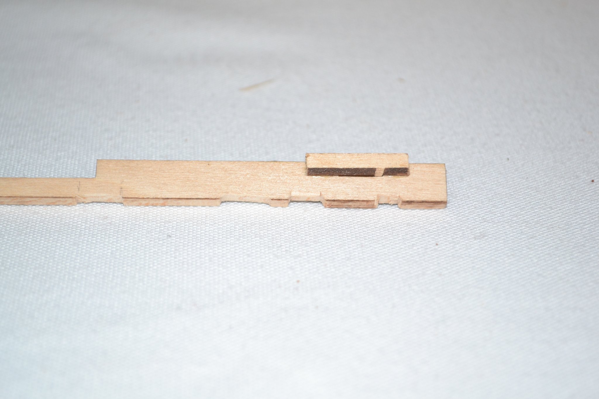
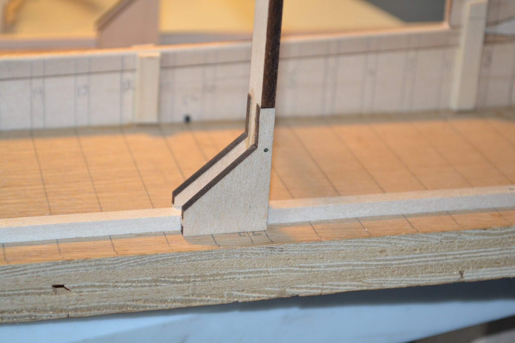
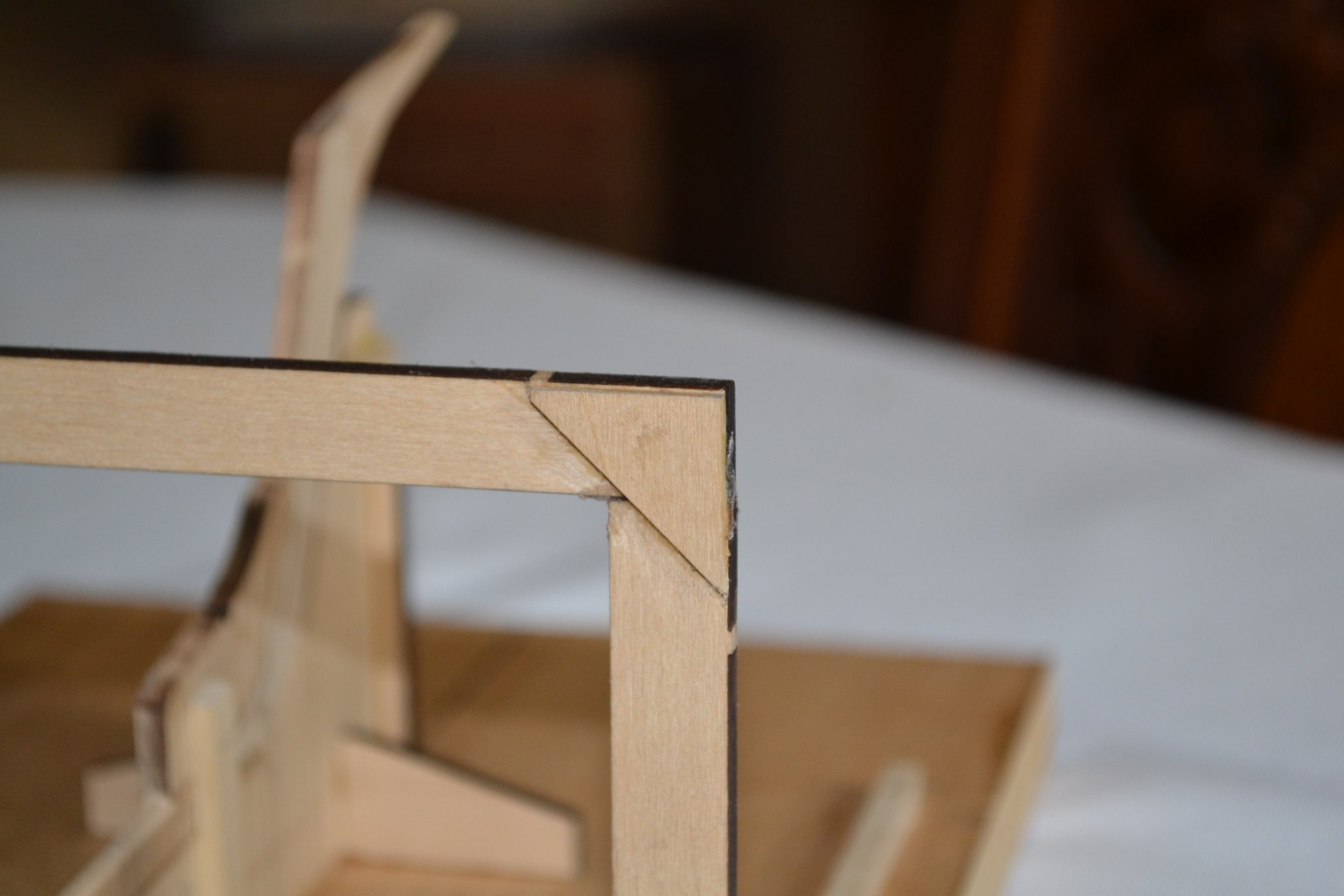
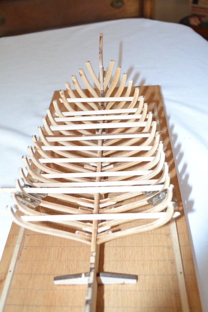
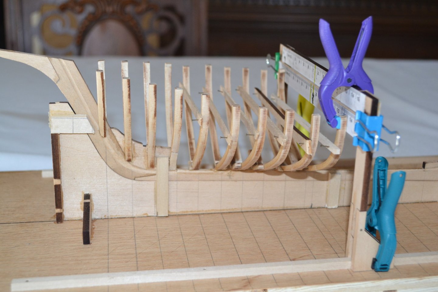
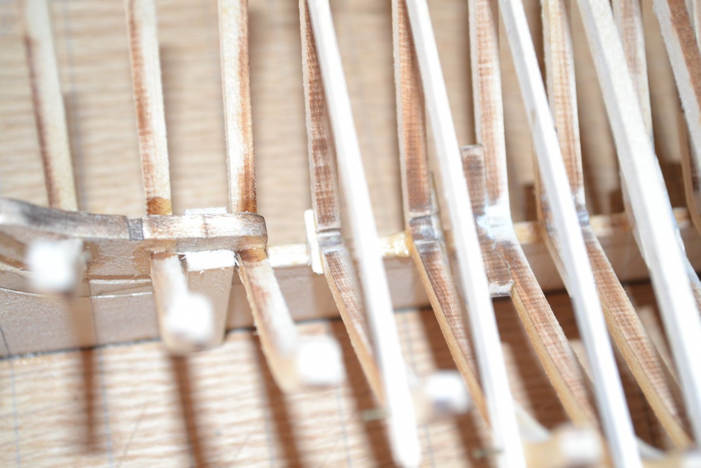
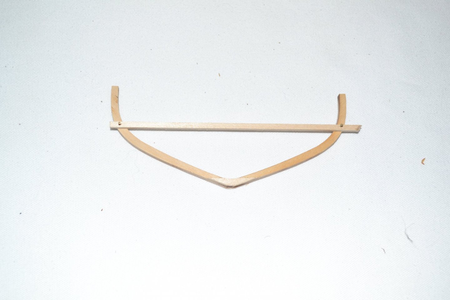
I seemed to have messed up the previous post, my computer skills are apparently about equal to my modeling skills! The first four frames attach directly to the keel assembly but the next several join in the middle and are glued to the top of the keel. This seemed a very weak area to me so for those that didn't have a laser cut "floor" included I reinforced the joint with strips of wood and added temporary to maintain the width. Hopefully they will not interfere with future bits to be installed, I couldn't see any issues on the plans but time will tell. An interesting issue, the building frame was too tall to support the top of the frames as I approached midship so I added another piece to accommodate the superior tops of the frames. I measured the width of the frames on the plans and made tic marks on the jig and also for the height, work quite well. One hint, the keelson rests upon t he frames above the keel so be sure to level and smooth that area, much easier before the frame installation than after as I learned!


-
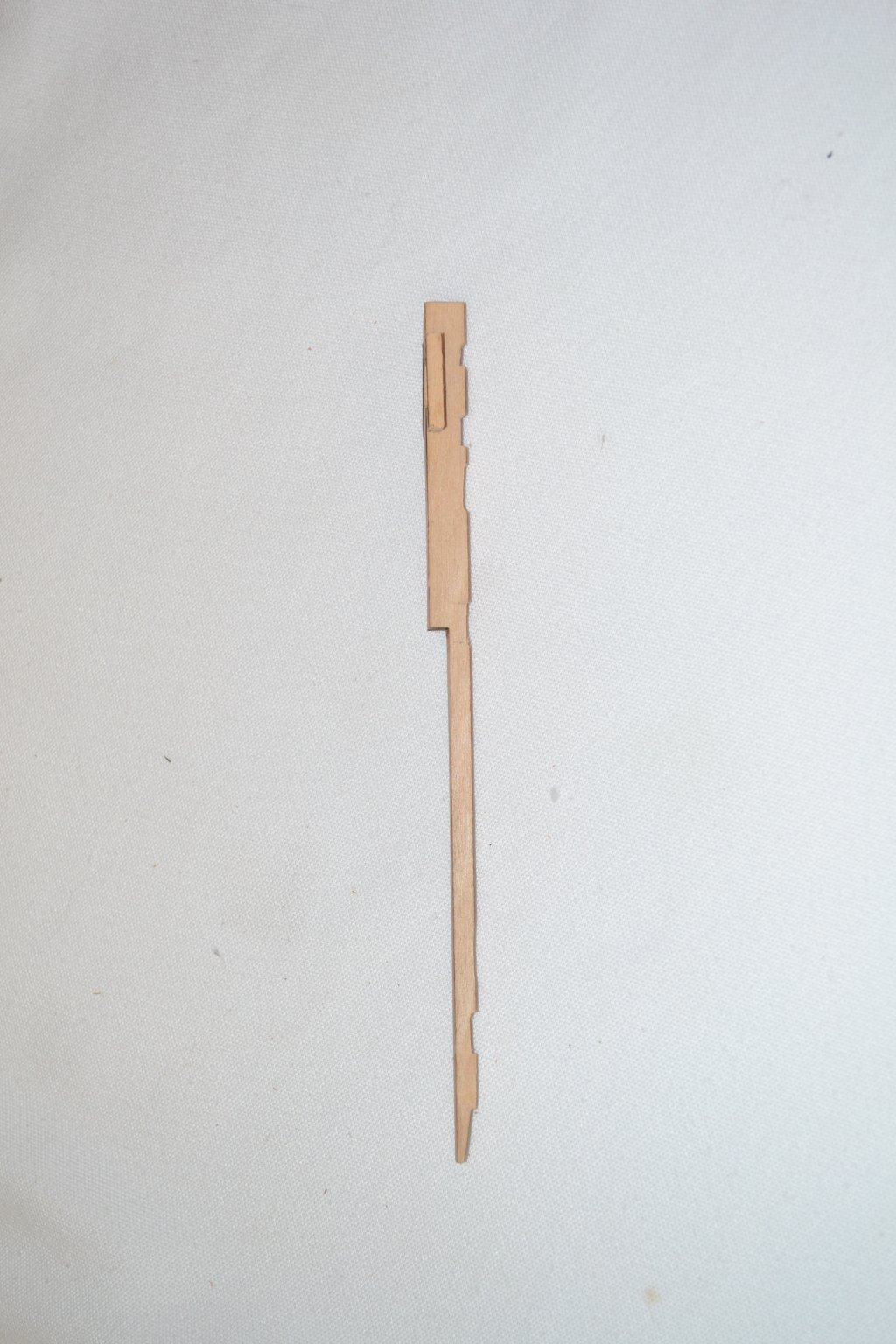
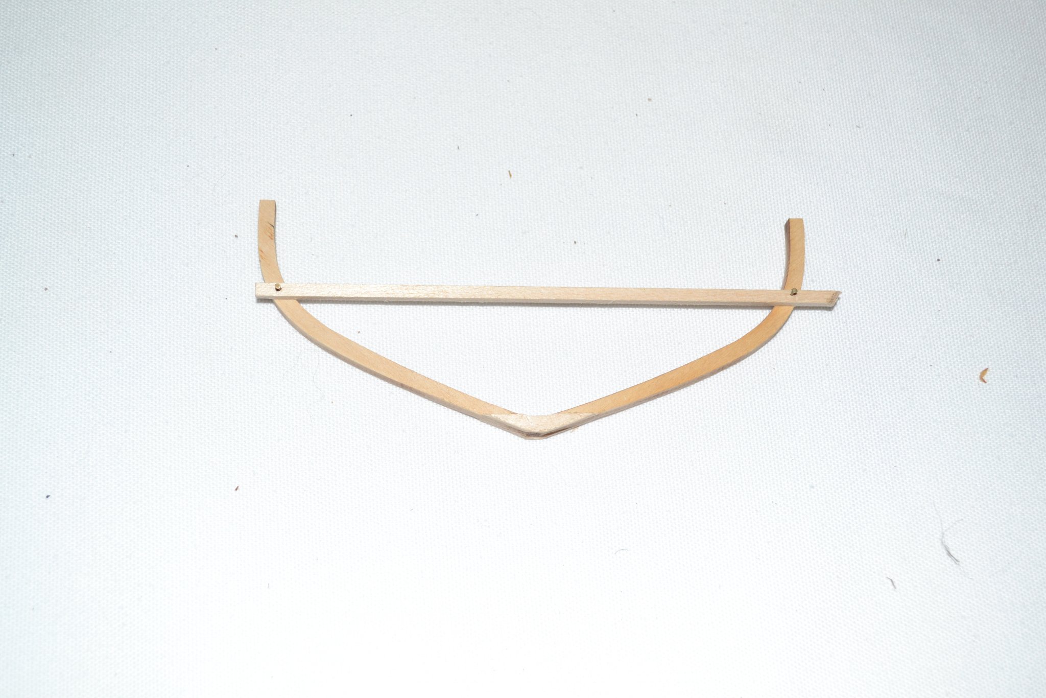
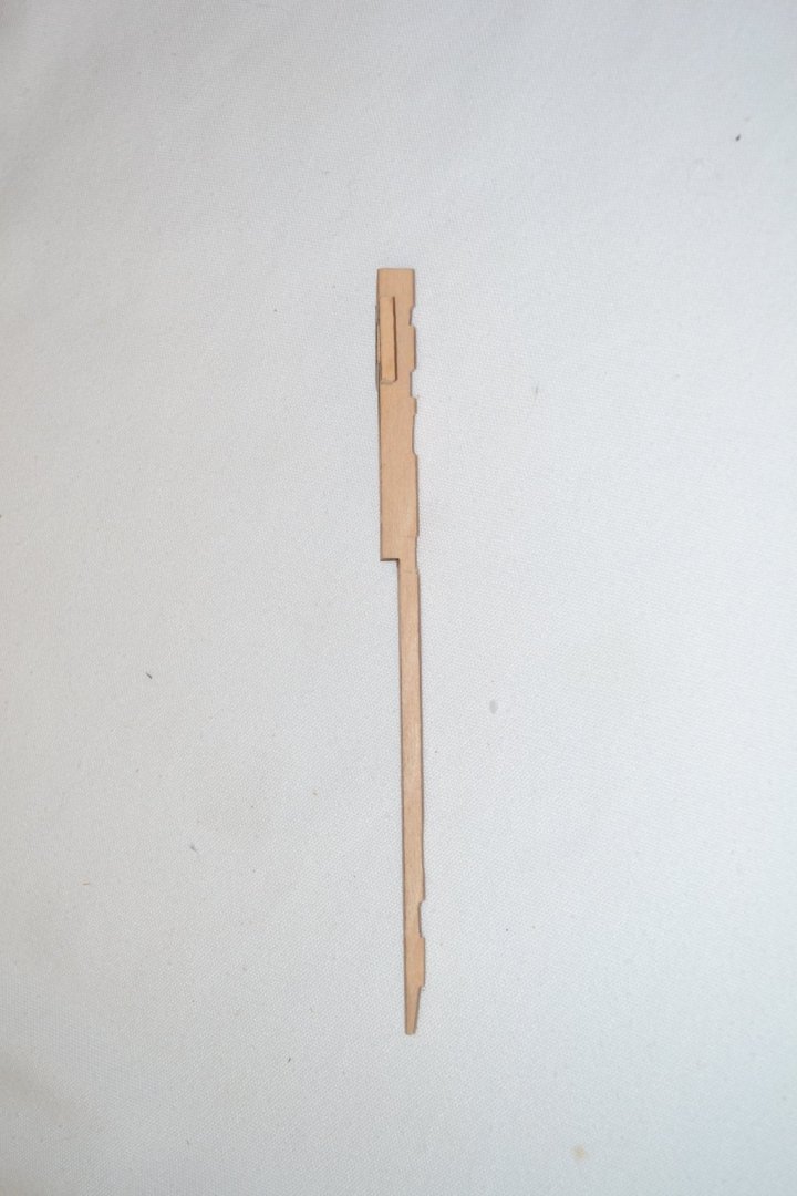
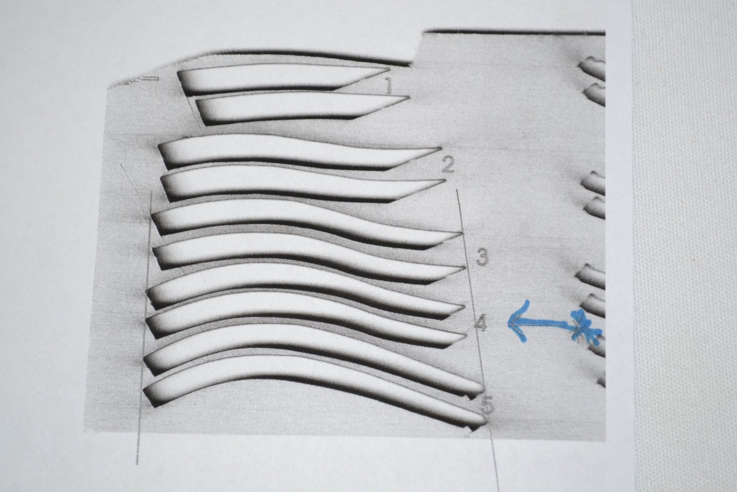
Time for an update, I started installing the frames and it was going swimmingly well until I reached frame #4. All the frames were installed per the instructions which emphasized that the need to be installed to the correct height above the baseboard to allow for a proper deck run.. I installed the port frame to the required height and it fell well above the rabbet so I added a shim down to the rabbet. On the starboard I added and extension to the top of the frame to meet the required height, neither worked out well. The rabbet at that point is a continuation of the top of the keel so it was not a layout or cutting error when I made the rabbet. I am now convinced the laser cut frame #4 is incorrectly cut as shipped on the matrix. It needs a few millimeters bore on the bottom end following the same curves. I have included a pic of the matrix and the frame is quite clearly cut to short. The correct course of action would be to tear both out and make new ones but I really don't have the expertise or tools to do that so I will think on it a while, perhaps shims will help? Any advice would be gratefully welcomed! This seems to be a known problem based upon post 27 in this build log
-
Don't know if anyone would be interested but here you go: https://www.leevalley.com/en-us/shop/home/books-magazines-and-dvds/55449-old-ship-figure-heads-and-sterns?item=49L8129
- 1 reply
-
- 2
-
-
Blackening brass
turangi replied to Bill Hill's topic in Painting, finishing and weathering products and techniques
Here you go: -
Welcome aboard! I was in OZ in March, couldn't get home from Auckland so took a detour to the West Island and made my way home. You will enjoy it here!
-
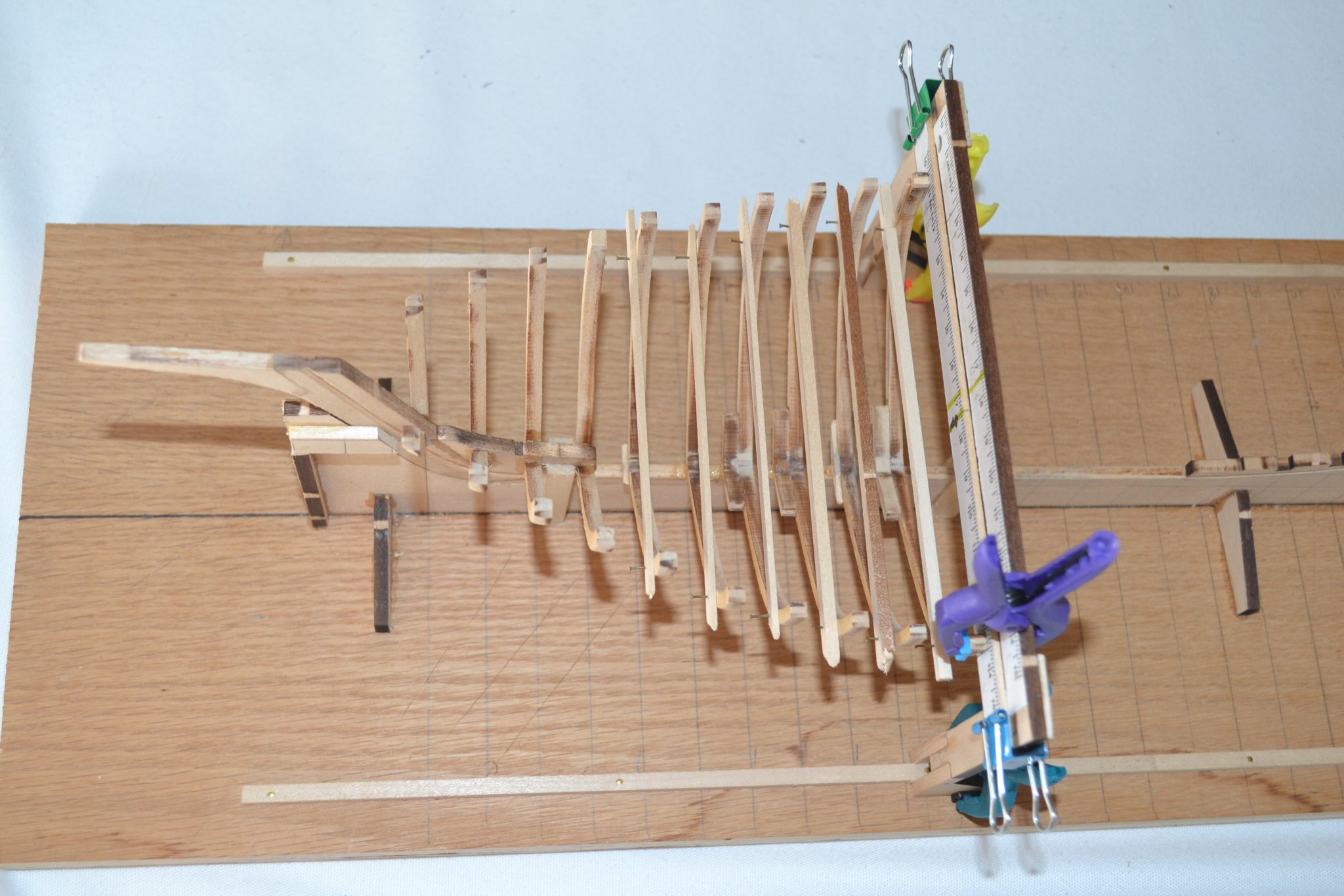
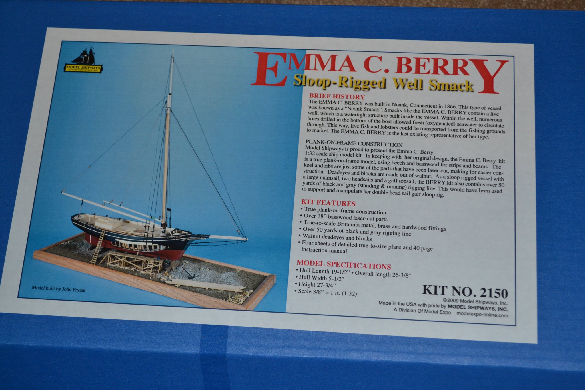
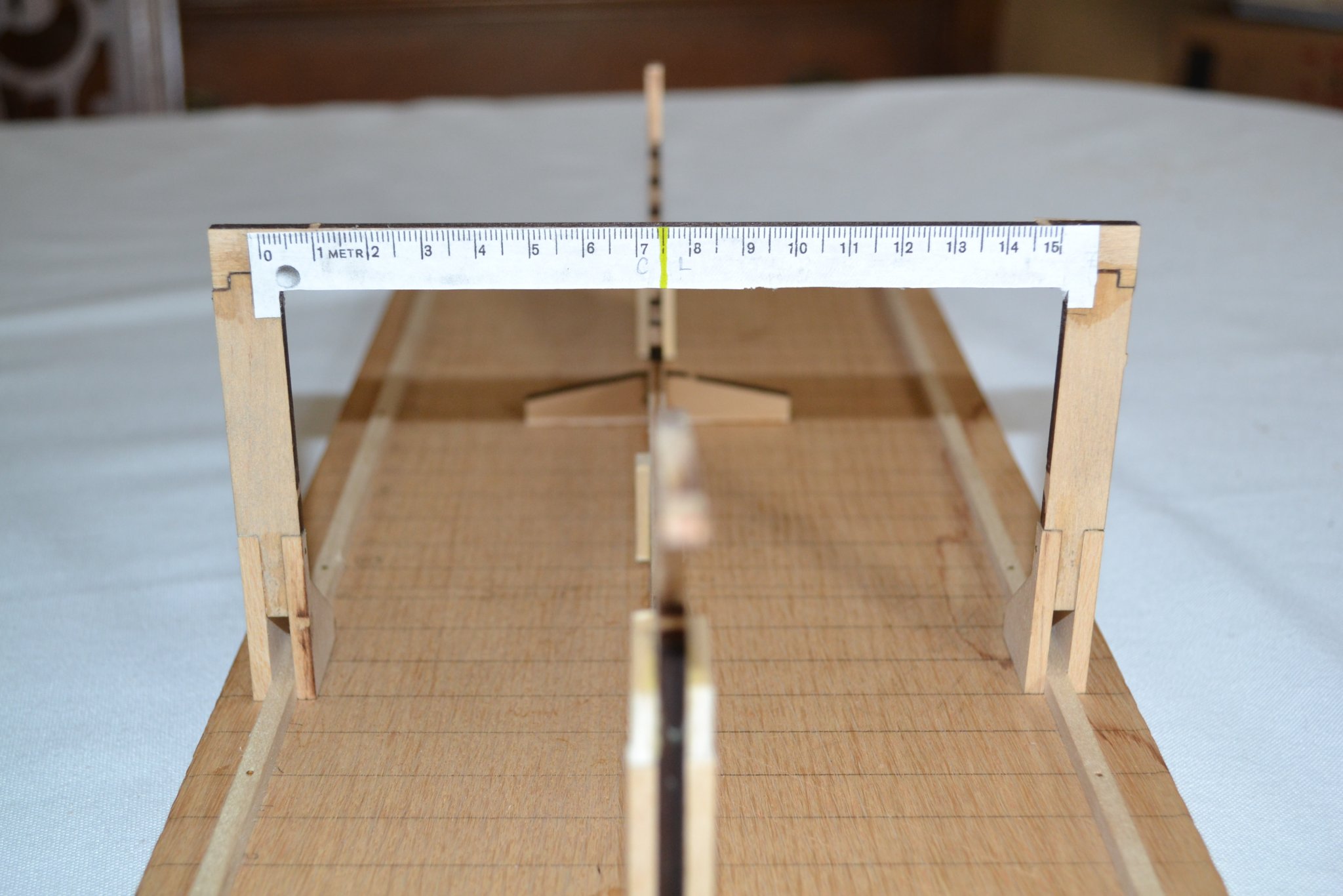
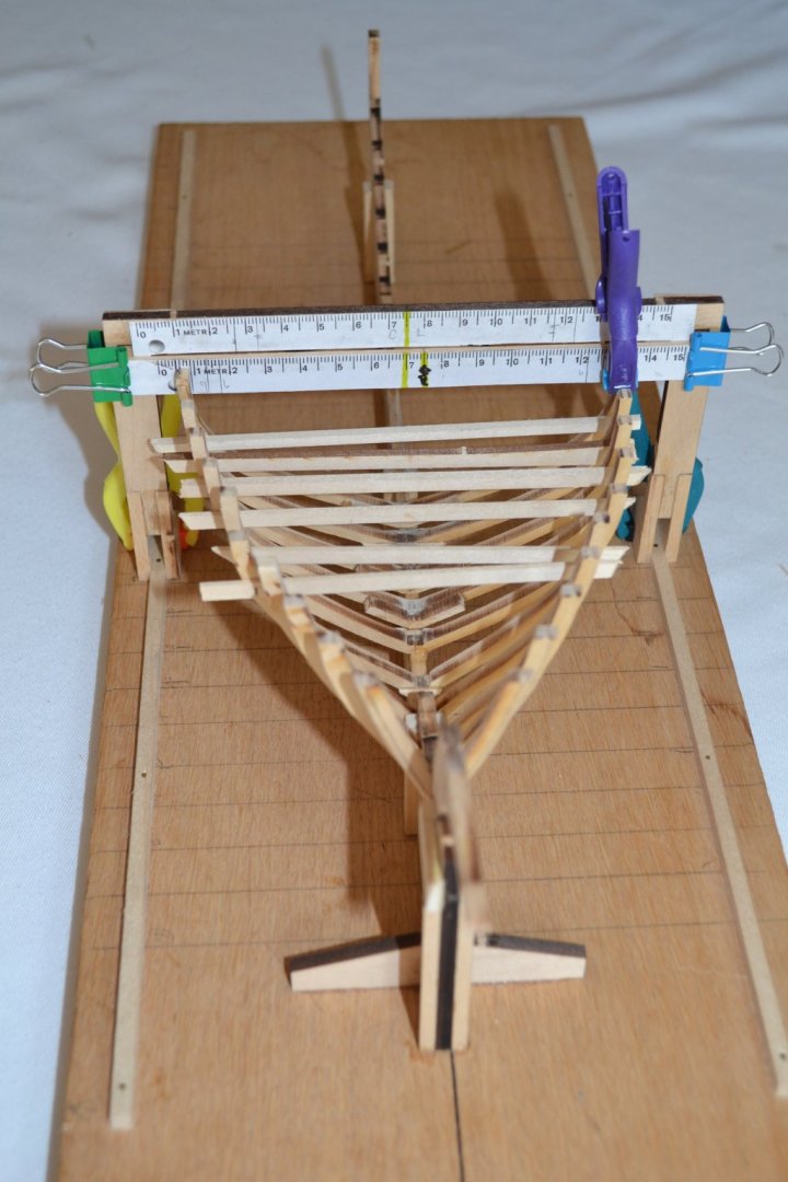
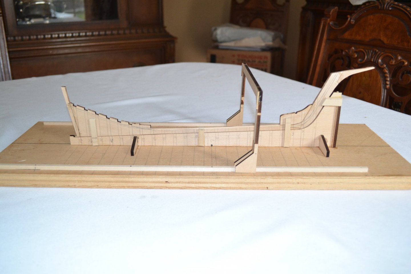
I am starting to build this kit as my first foray into a POF model so bear with this beginner. I am included a picture of the box but not the contents as I neglected to take a photo. I probably won't do a step by step log as it will bore the more experienced members and much of it is self explanatory, instead I will concentrate upon my challenges and mistakes and will probably asking the experienced members frequently for Help! There is a rather impressive amount of wood which I did inventory and label by size and checked off all the other items. I started by building the keel section per the plans and instructions and it was quite straight forward. I then hopefully correctly marked the frame locations on that assembly. I next turned to the building board, marked a center line and also the frame locations. Next I built the lofting jig for the frame installation and took pains to be sure it it was square and plumb to the board. I thought the frame was critical to the proper frame placement so went beyond the instructions by gluing and pinning the runners and added reinforcement to the rear of the frame. I also copied a metric ruler being sure it reproduced at 100% and glued it to the top of the jig, marked the centerline so I could transfer the measurements from the plans to the ruler on the frame, I think I wore out two pair of eyeglasses to be sure it was right😯. So it begins, I will endeavour to to present my problems and mistakes and hopefully a few successes. I suspect it will be slow going, like me at my age! Hope someone may find it useful or at least good for a laugh at my beginner mistakes. As always, any comments, suggestions or criticism would be very welcomed and appreciated!


-
I will follow this with great interest as it is the next model to butcher in my queue!
-
Beautiful job, you should be proud!
-
Great build log but unfortunately the last OP post was almost 5 years ago. I am currently building the same model and have run into the same issue mentioned in post #27 with the frame 4. I set it to the height indicated by the plans but there is a considerable shortfall down to the rabbet. I suspect a laser programming error resulted in a frame that is too short. I am going to attempt to splice in a piece at the bottom to meet the rabbet line and try to create a reasonable fair line. Most obvious solution would be to make a new longer frame but I don't have the necessary tools or experience to accomplish that task. I'll post the results. Any advice from experienced modelers would be gratefully accepted!!
-
I recently built Model Shipways Picket Boat. The fairing lines were laser marked and I used a belt sander to do an initial fair before installing them and a final hand sanding once installed, saved a lot of hand sanding! See post #3 in this thread.
-
Excellent start, I really like how the deck turned out! Look forward to following the build. Adding Ammonia to the soak seems to be helpful according to some although I have never tried it.
- 29 replies
-
- 2
-
-
- constructo
- prince
- (and 1 more)
-
Remember, seeking perfection can be the enemy of good!
- 38 replies
-
- 1
-
-
- vanguard models
- fifie
- (and 2 more)
-
The model looks good so far! I am a relative newcomer to the hobby and this forum is a tremendous resource. Reading the build logs and other postings have really helped me. Don't hesitate to ask any questions, I have found the members here very willing to help and encouraging without exception! I lok forward to following your progress.
- 38 replies
-
- 2
-
-
- vanguard models
- fifie
- (and 2 more)
-
Lower cost (?) shiny metal parts
turangi replied to Patrick Matthews's topic in Metal Work, Soldering and Metal Fittings
I wonder if the uncured parts could just be put out in the sun to cure? A strong source of UV light as my Dermatologist will attest. -
Welcome, great models! You are a kid, I am a beginner at 71, loving it.
-
I am enjoying following this thread! I was born in Canada and many relatives worked for CP, CN was not mentioned in polite company. The family story was we didn't have blood in our veins but locomotive smoke. I had an Uncle who was an executive with CP and traveled by train from coast to coast and spend much of his time building railroad models on his trips. Sure wish I had one or two.
-
The model looks great! I look forward to your next one. Not sure I can wait 7 years to see it completed though.☺️
-
Which Glue
turangi replied to Old Fart's topic in Building, Framing, Planking and plating a ships hull and deck
For wood to wood I use Titebond, if it is impossible to clamp I sometimes use CA or a combination of CA to spot glue along with Titebond. For metal to wood or metal to metal I will use 5 minute epoxy or solder if practical. I have never have used contact cement in models and would be very leery of it's longevity. -
Fuji, welcome from another Illinois resident!