MORE HANDBOOKS ARE ON THEIR WAY! We will let you know when they get here.
×


Bluto 1790
-
Posts
324 -
Joined
-
Last visited
Content Type
Profiles
Forums
Gallery
Events
Everything posted by Bluto 1790
-
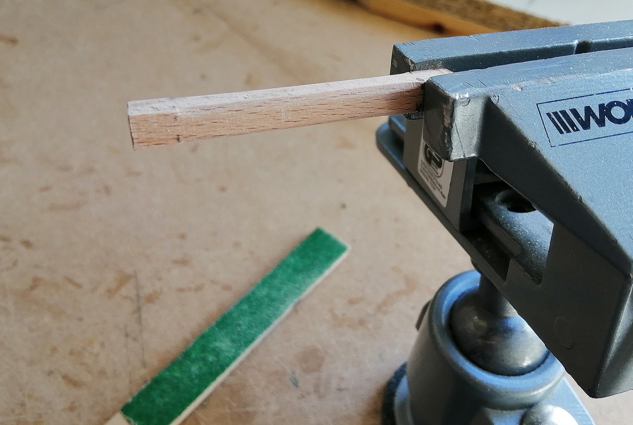
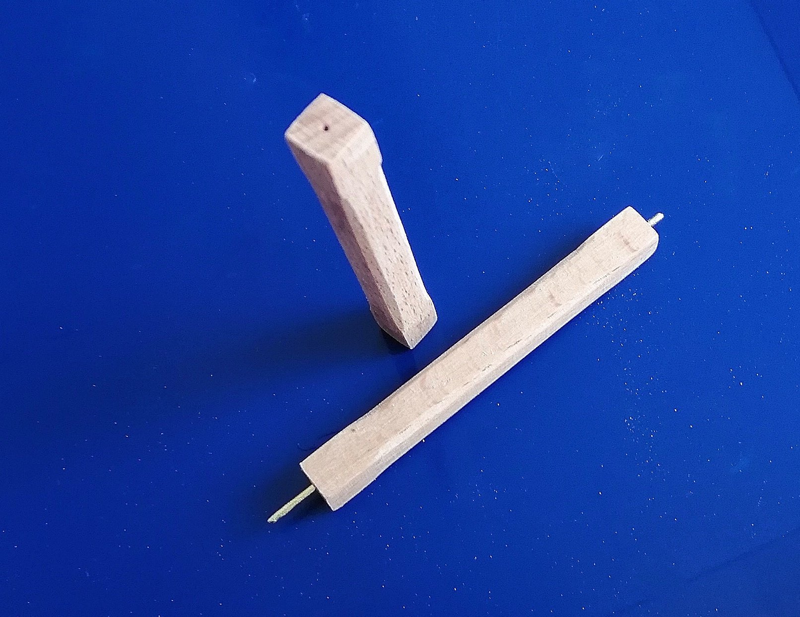
 Re-visited the aft end of the hold and fitted a couple of racks, each of which has a coil of rope on it - more to follow when I get some more suitable rope. Then returned to the fore end of the orlop deck to get the two deck beams secured since the carpenter's walk and cable tier were now done. Although quite small, turning the deck pillars proved quite tricky. I was using 6mm square stock and as I don't have a 4 jaw lathe chuck I could only use the point of the drive attachment in my drill and the point of the idler at the other end so it was a bit of a slow process. (It was only the central beam pillars that get turned, the cable tier pillars are just square in section.) Still have to do the carlings, ledges and knees for these two beams but I've made a start on the structures of a few of the rooms at the aft end of the orlop deck to allow me to get the other two deck beams fixed in place.
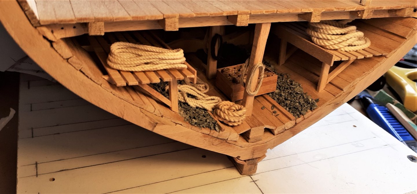


- 66 replies
-
- 12
-

-
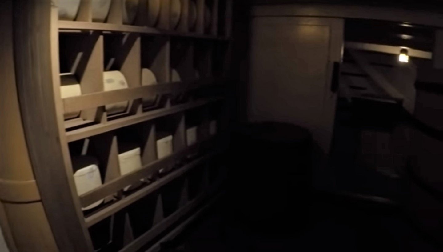
Thanks for your comments El Cid, Allan and Henry. El Cid ~ I've ordered a full length mirror and some frilly underpants off ebay. I've viewed several walk-thru videos of Victory on youtube hoping for some inspiration and will probably try a cabinet or two and some shelves similar to these ones in this screenshot from one of the videos >
-
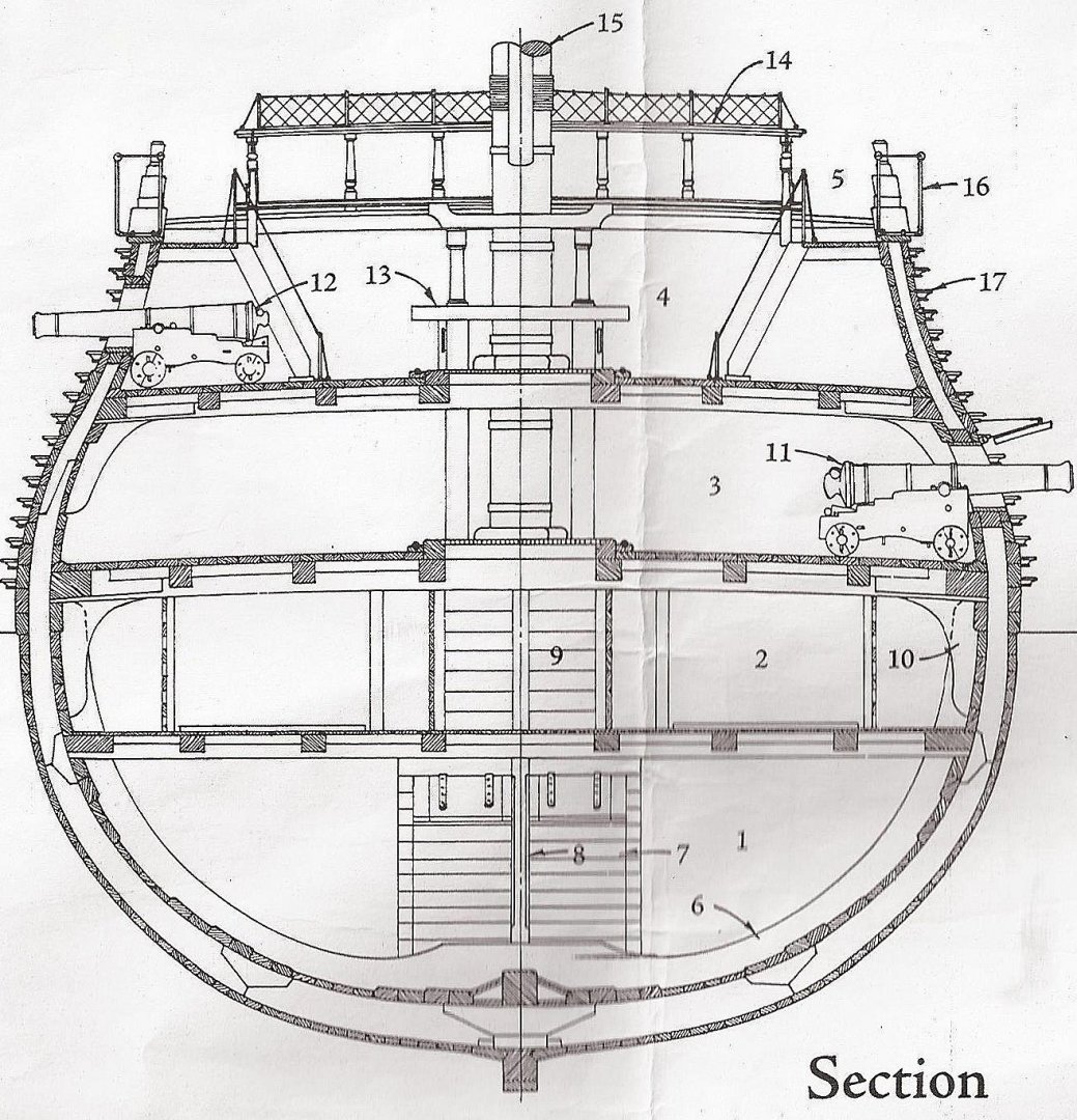
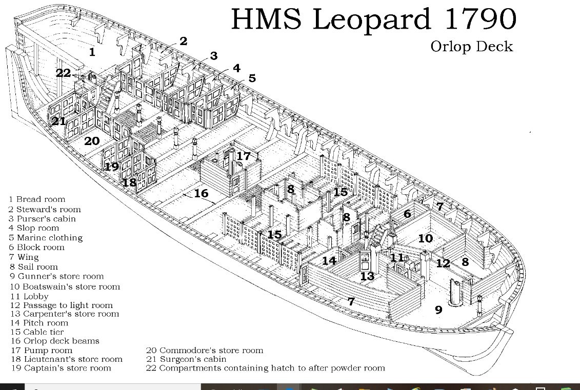
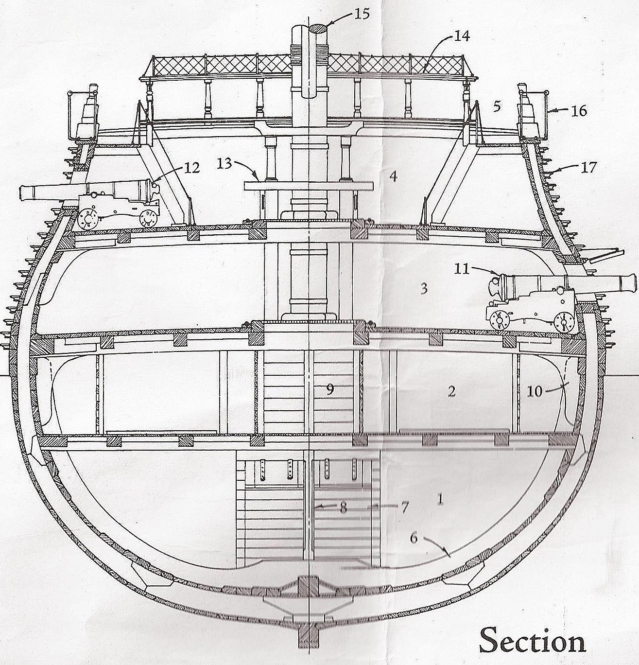
There are 3 rooms in the aft end of the orlop deck that will be included in the section that I'm building. One of them is #5 in the drawing below. The other 2 rooms, #18 & #19 will also be included. Room #5 is shown as Marine Clothing. How would the inside of that room be configured? I assume it probably had shelves attached to the partition wall and possibly even to the inner hull -- but I only have that drawing above and have no idea of what may have been in that room. So I'd be grateful for any information coming from you guys. Also, the rooms #18 (Lieutenant's Store Room) and #19 (Captain's Store Room) -- how would they have been configured? What kind of fittings would most likely have been in these rooms? Thanks in advance.
.jpg.dc3a6335416cafd7d2b6b3a54c2de115.jpg)
-
Hi Tom, I think that side is "more righter" and is also "more betterer"! When I made my other model I didn't bother with any "correct" beams, carlings and ledges as virtually everything inside the ship would not be seen. (but I wanted to make this one "correcter"!) As you said, it has been great practice and a chance to see if I could do some of the 'stuff' I see on so many other builds.
-
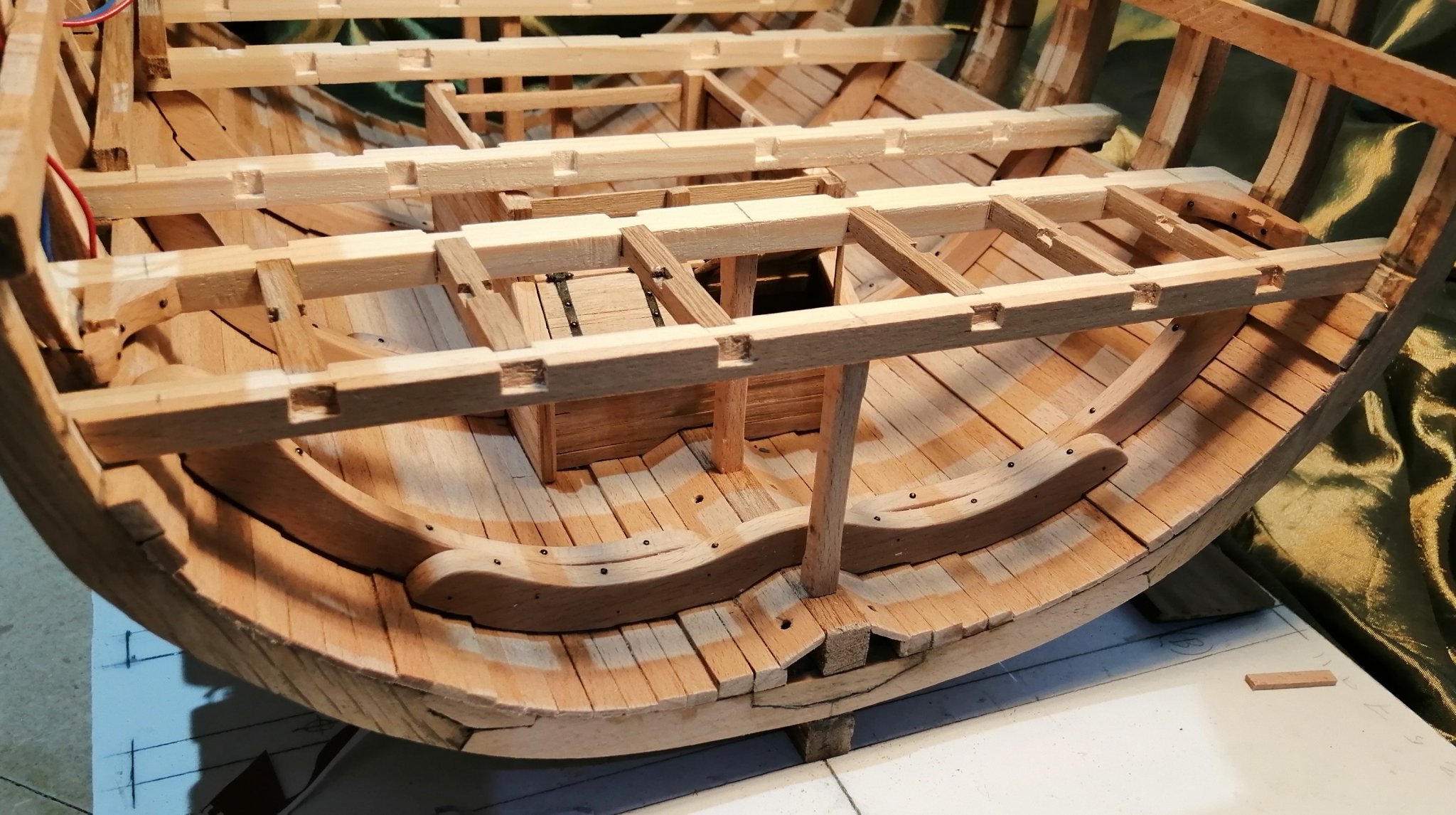
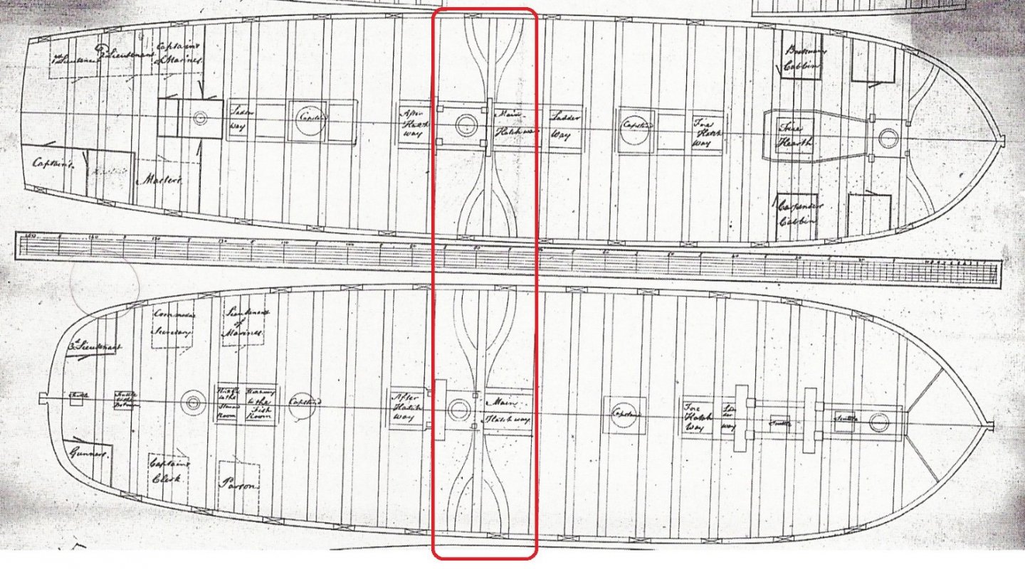
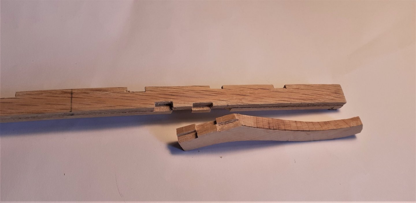
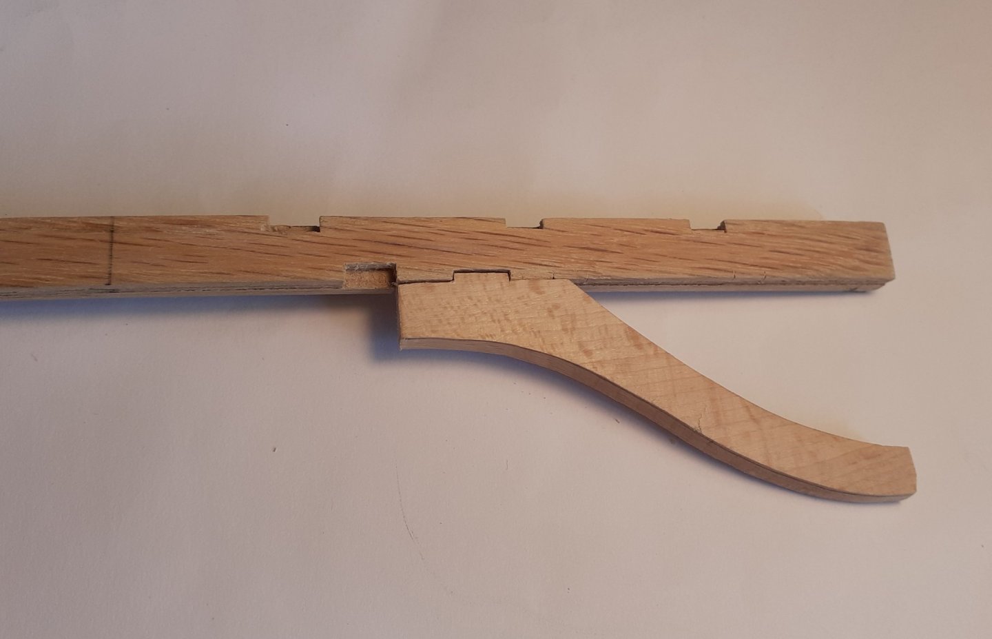
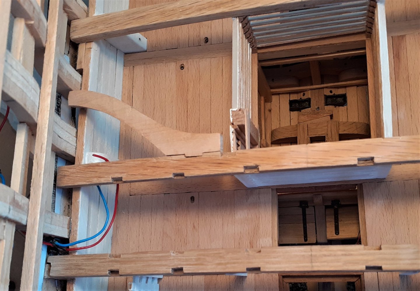
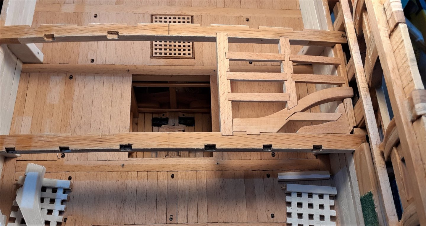
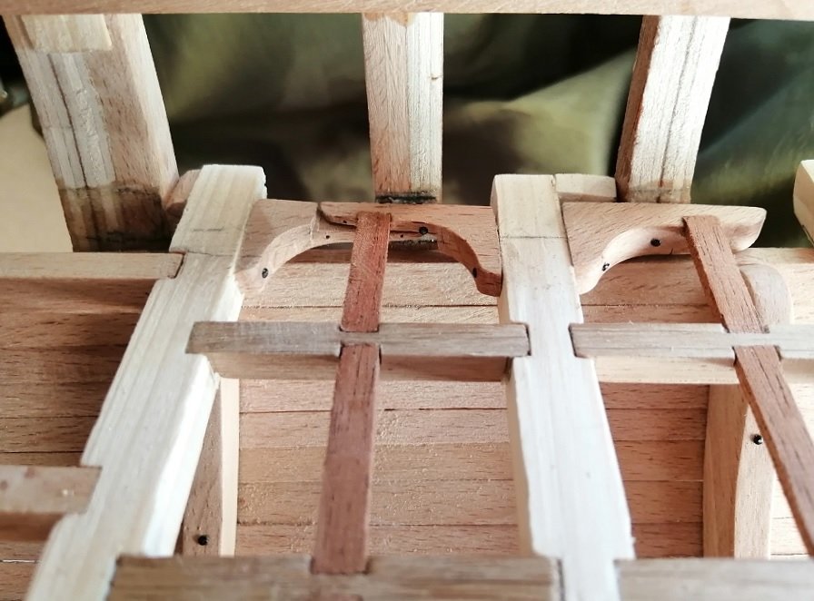
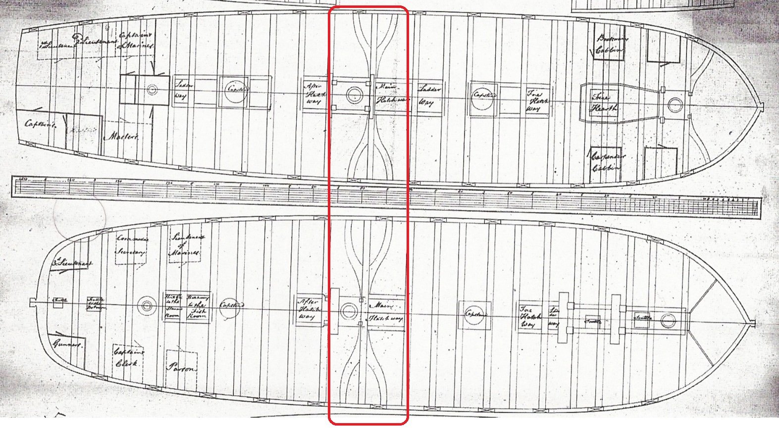
Thanks Tom (usedtosail) and Mark for your comments and the others for the likes and visits. Since I had finished the upper well structure and everything in that central part of the orlop deck seemed OK I was keen to have a try at the more complicated mid-ships beam which has the beam arms attached. My only previous experience with deck beams, carlings and ledges was with the slightly simpler, flat and square orlop ones. The curved beam arms looked more complicated, although the basic cutting of them was reasonably straightforward with the bandsaw and smoothing them with a sanding drum in the drill press . . . but first I had to decide on their configuration. I had a good rummage through the Fifty Gun Ship book (there are no plans for the deck beams in the plans/drawings I have) and could only find a few drawings of beams for 50 gun ships from an earlier period. Here is the best one I could find with the mid-ships beam with beam arms circled in red > Having looked at so many build logs of Royal Navy ships from the late 1700s, what I saw in that drawing above differed somewhat as far as that central beam was concerned, so I opted to go with what I was seeing in the other builds. This is first attempt at the rather complicated joint between the beam and the arm > . . . and 'clicked' together > First dry fit > Both beam arms with one carling on each > On the models I've viewed there have been some with two ledges between beams, some with three ledges and some with four ledges, so, at first I opted to go with two ledges > I was quite happy with that first attempt, but the more I looked at it the more I began to think there probably should be at least three ledges between the two beams. So ~ ~ ~ for the other side I decided to go for three. Doing three ledges involved creating more mortices -- reasonably easy to do the 'square' mortices, but a bit more of a challenge to do the angled mortices in the beam arm and in the lodging knee. Here, a bit of an incongruous picture showing the difference between the two sides > OK ~ it may look a little odd but as the deck will be planked and nothing of the beams, carlings and ledges will be seen, I am leaving it the way it is. There was quite a lot of work and time spent on these beam arms and associated 'bits' - even just the simpler starboard side, and in reality it was something of an experiment as I wanted to see if I could tackle that new challenge. Here, the beams, the arms, carlings and ledges are now glued in position with the upper well also in position. In this picture only the starboard lodging knee was still to be fitted (it can be seen lying on the cable tier) >


- 66 replies
-
- 12
-
-
HMmmm . . . . . 2,852 clove hitches? ~ are you absolutely certain you counted them correctly? 😄😄😄 It's looking great Tom. It's on the home straight now, and as you say, the model has really come to life now.
-
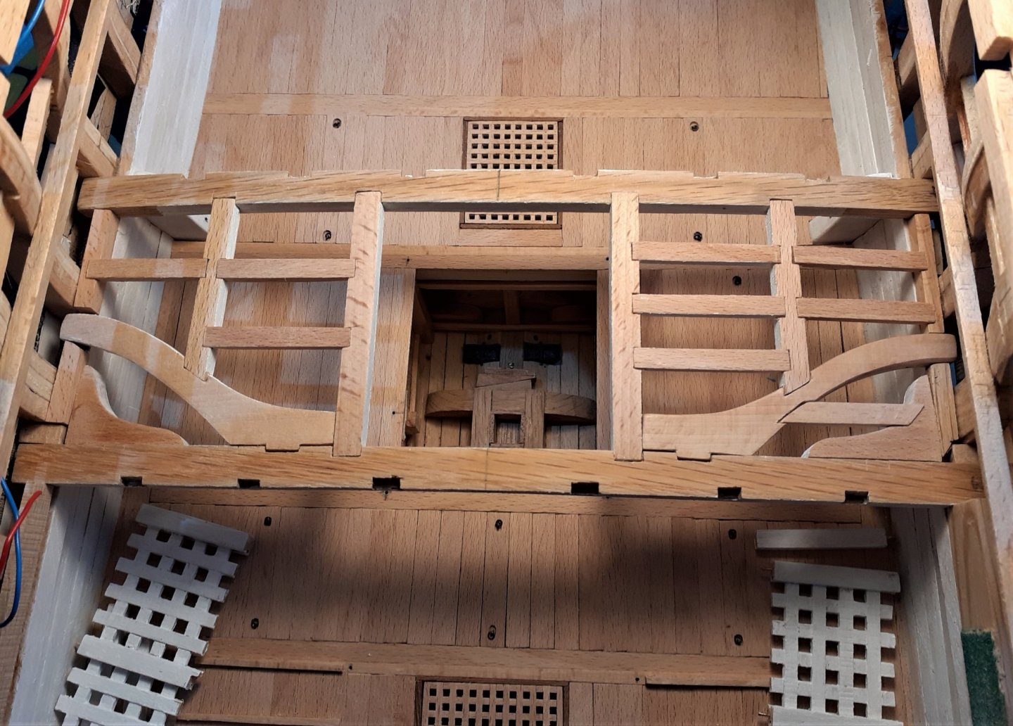
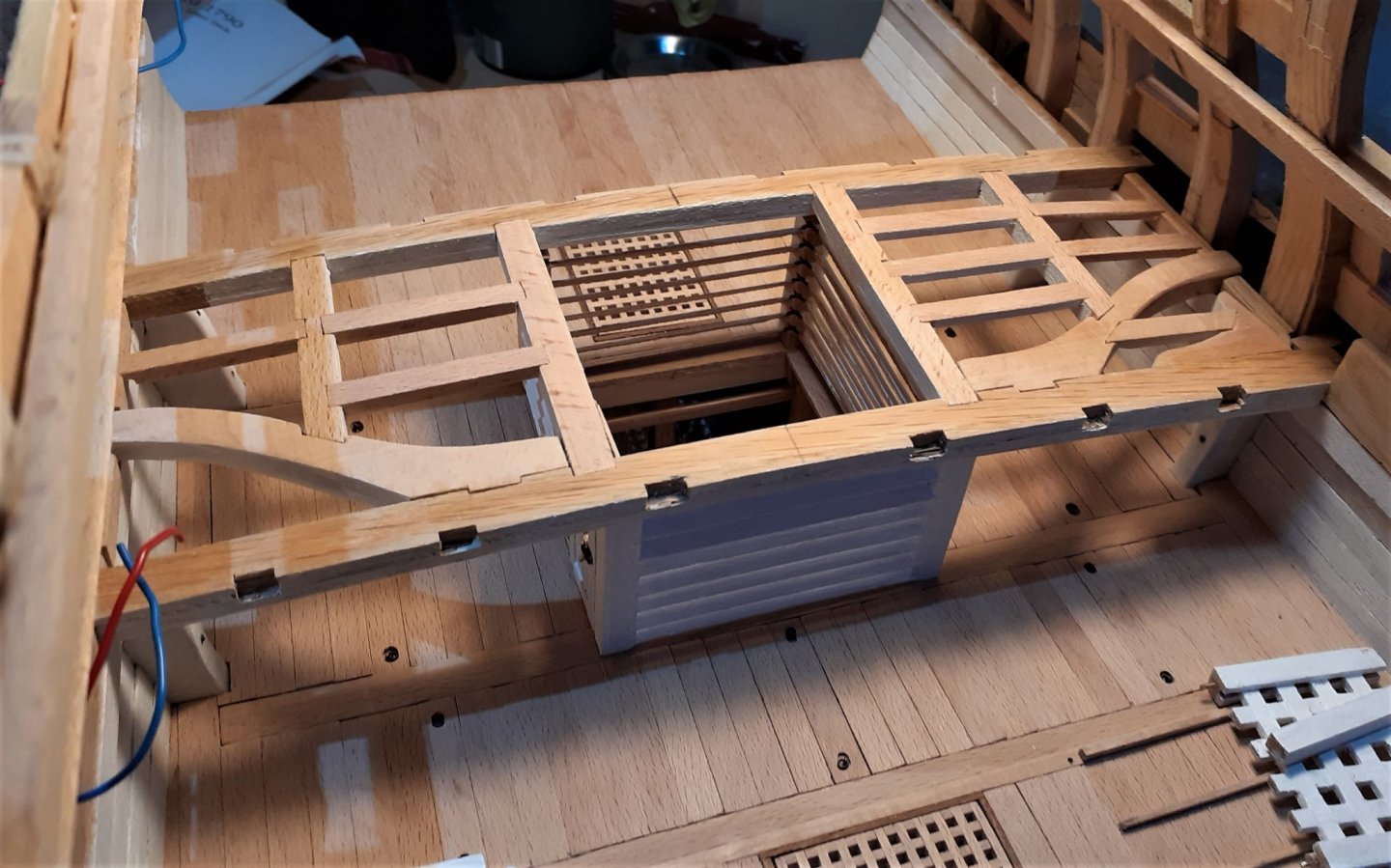
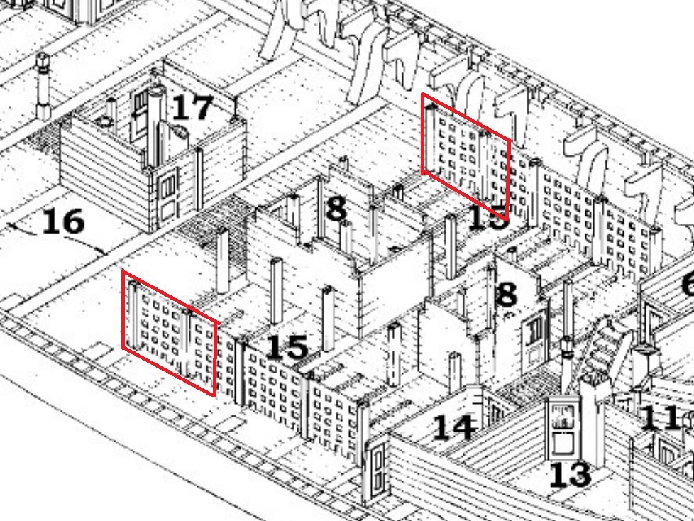
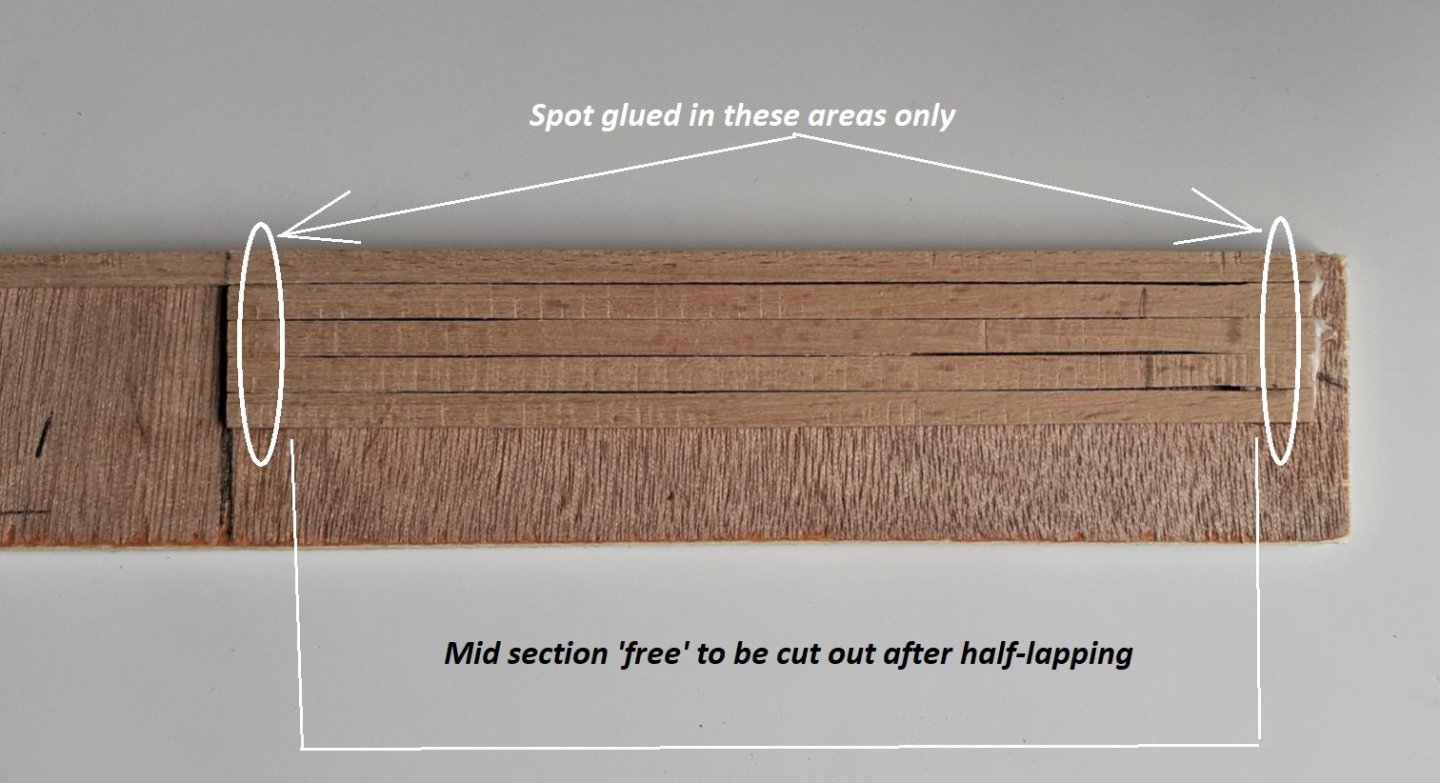
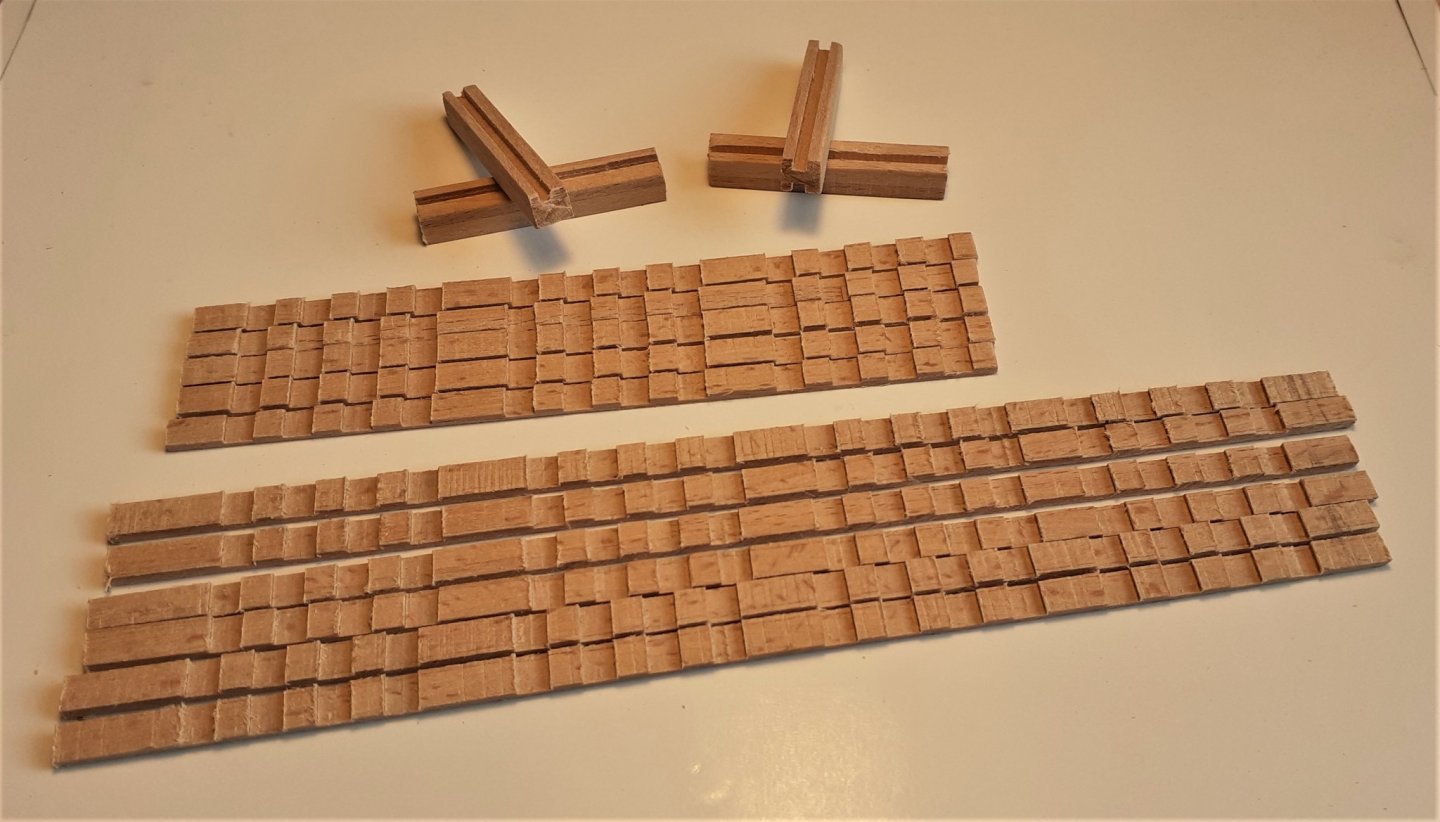
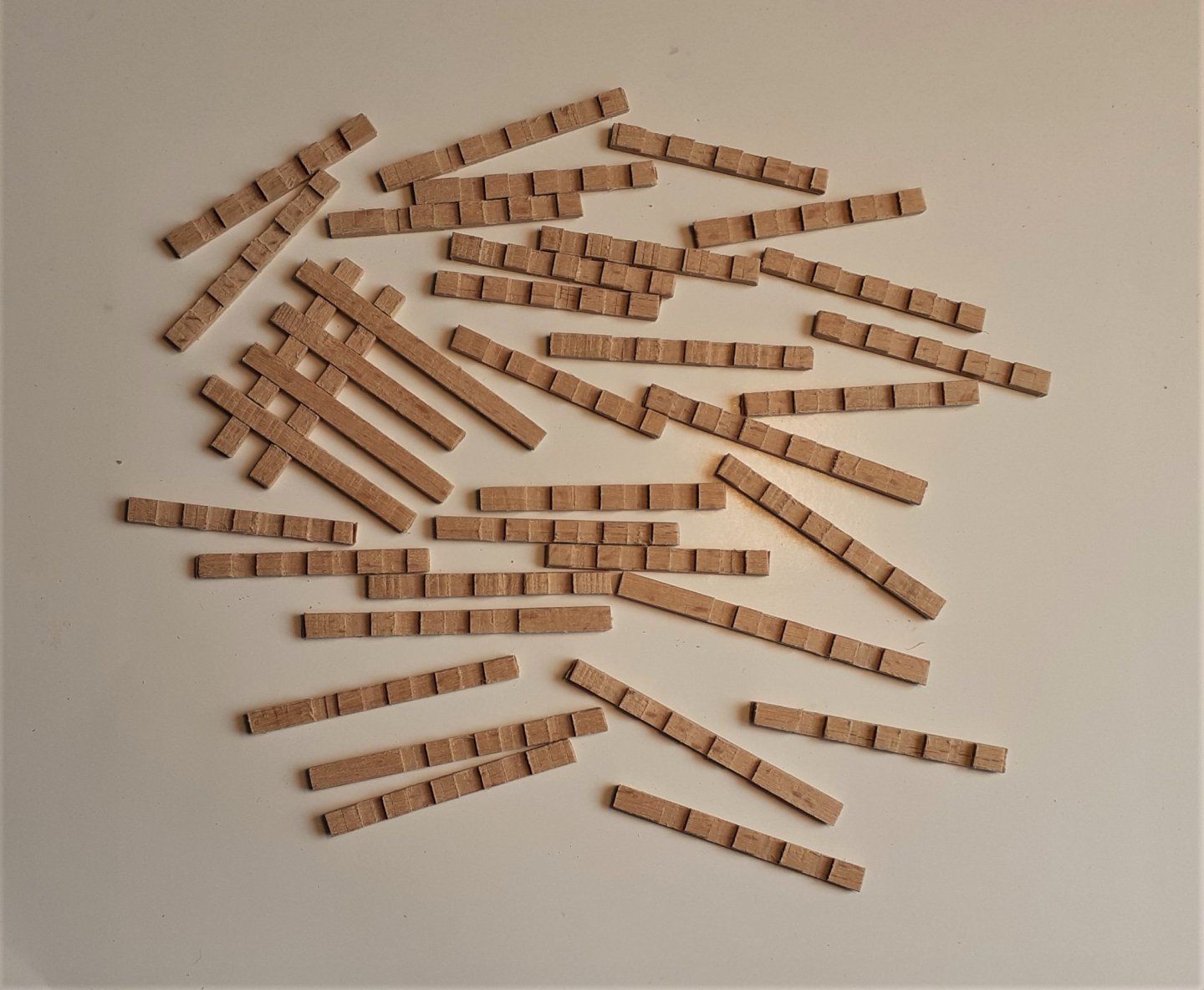
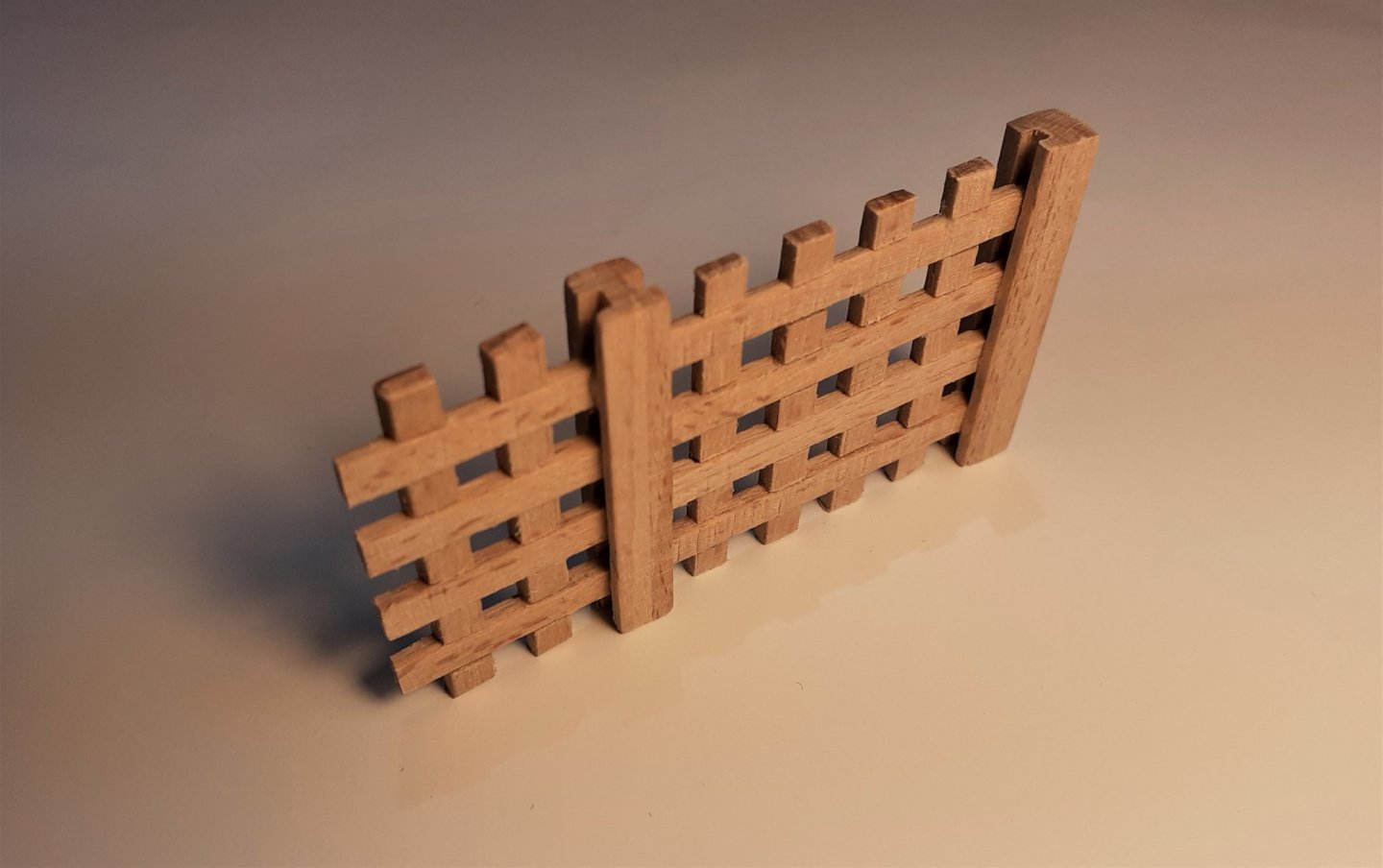
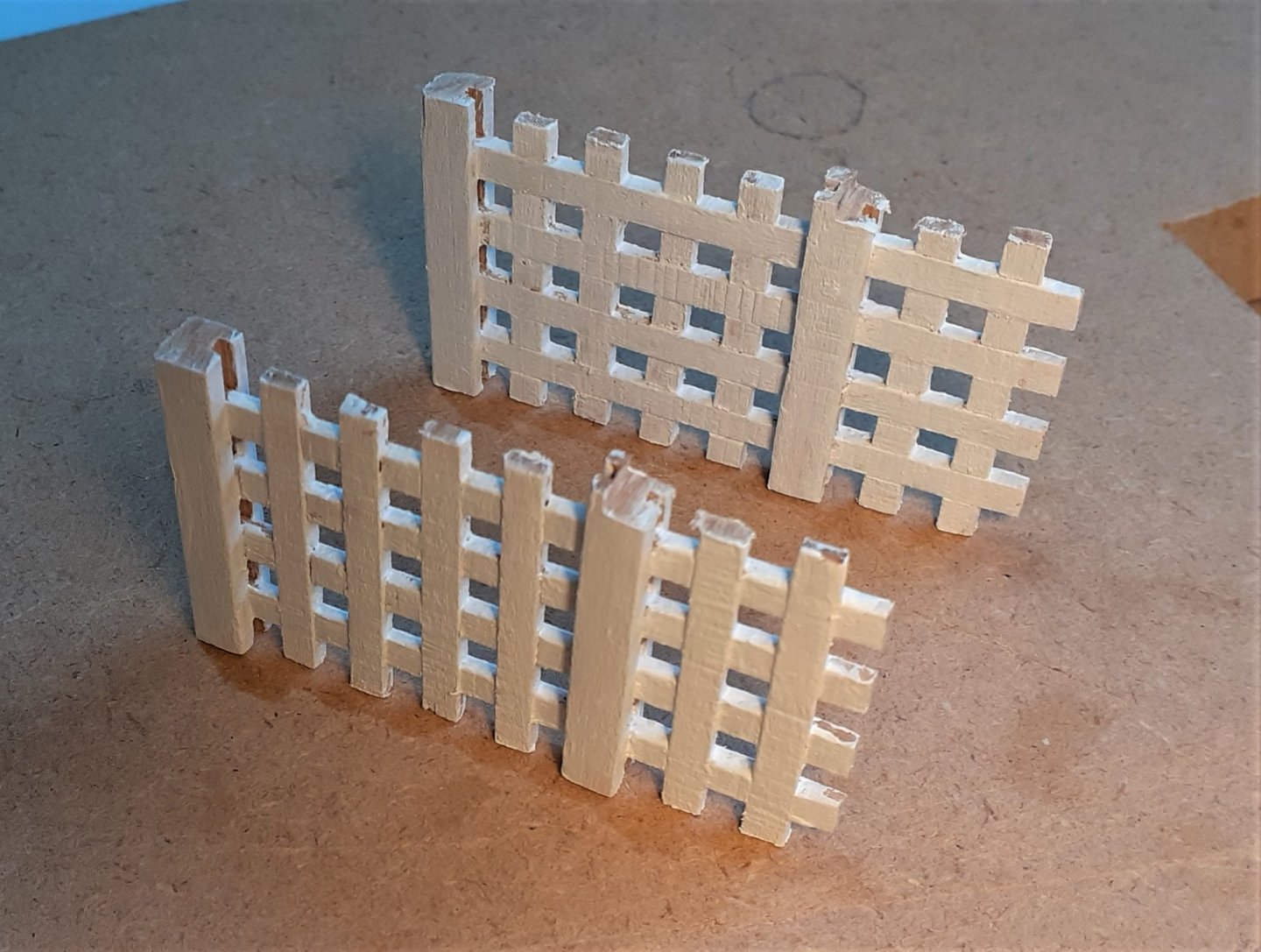
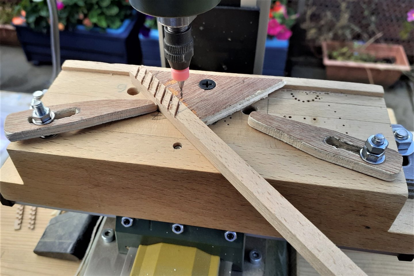
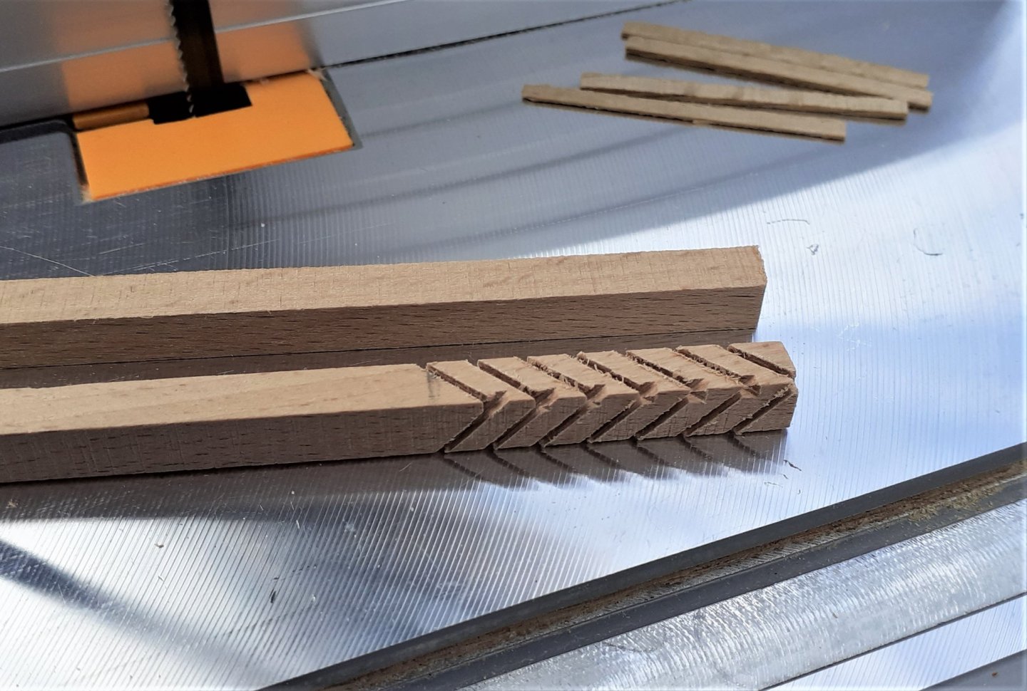
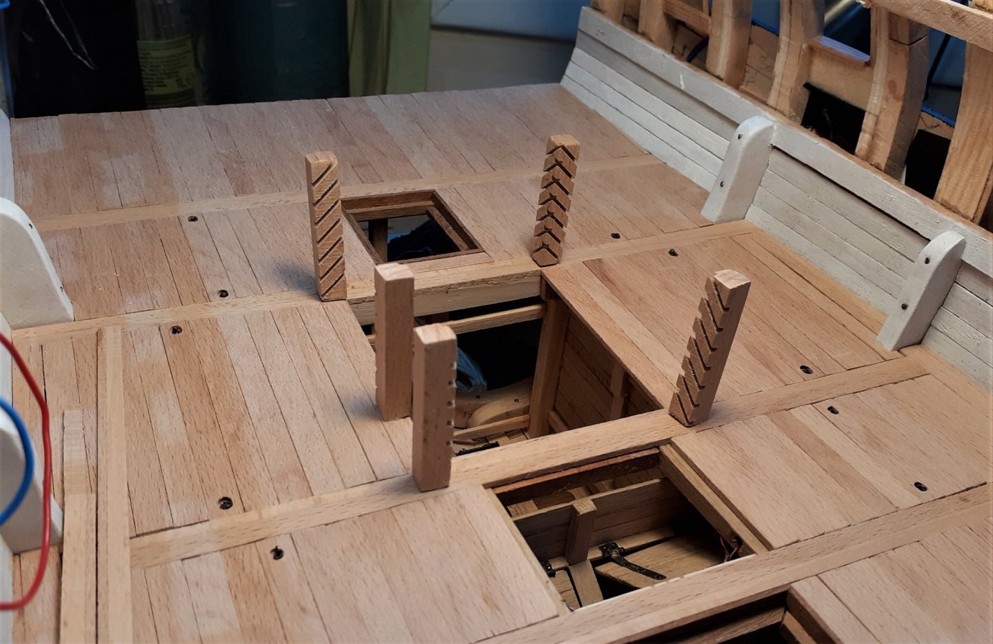
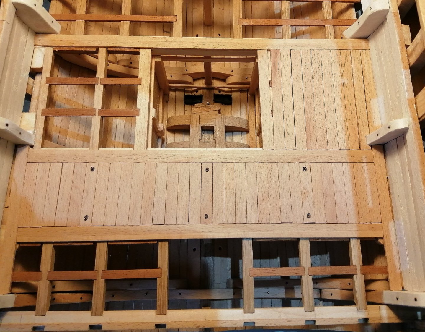
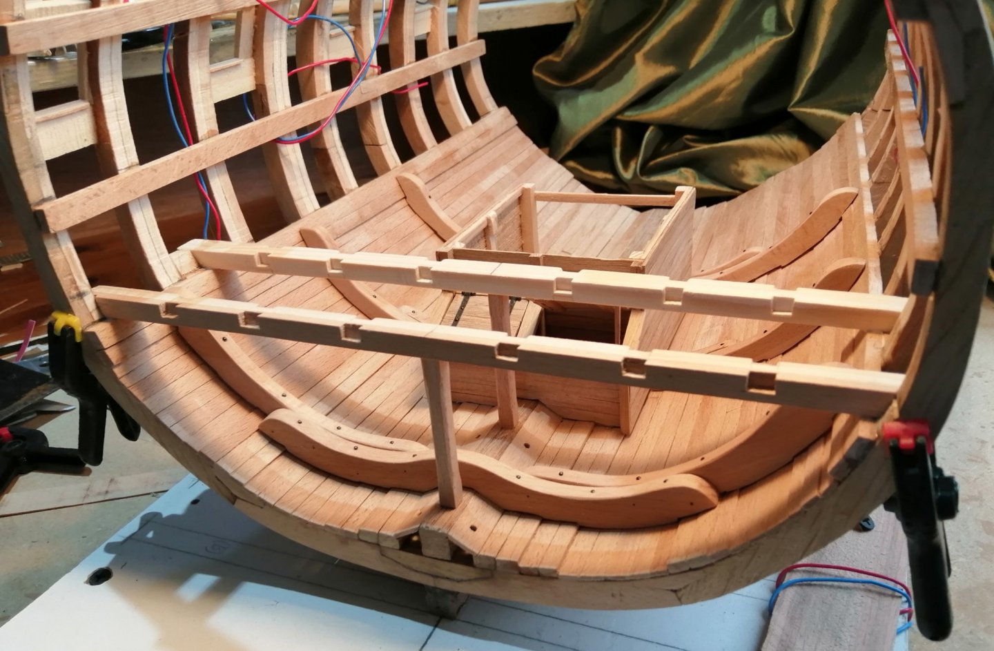
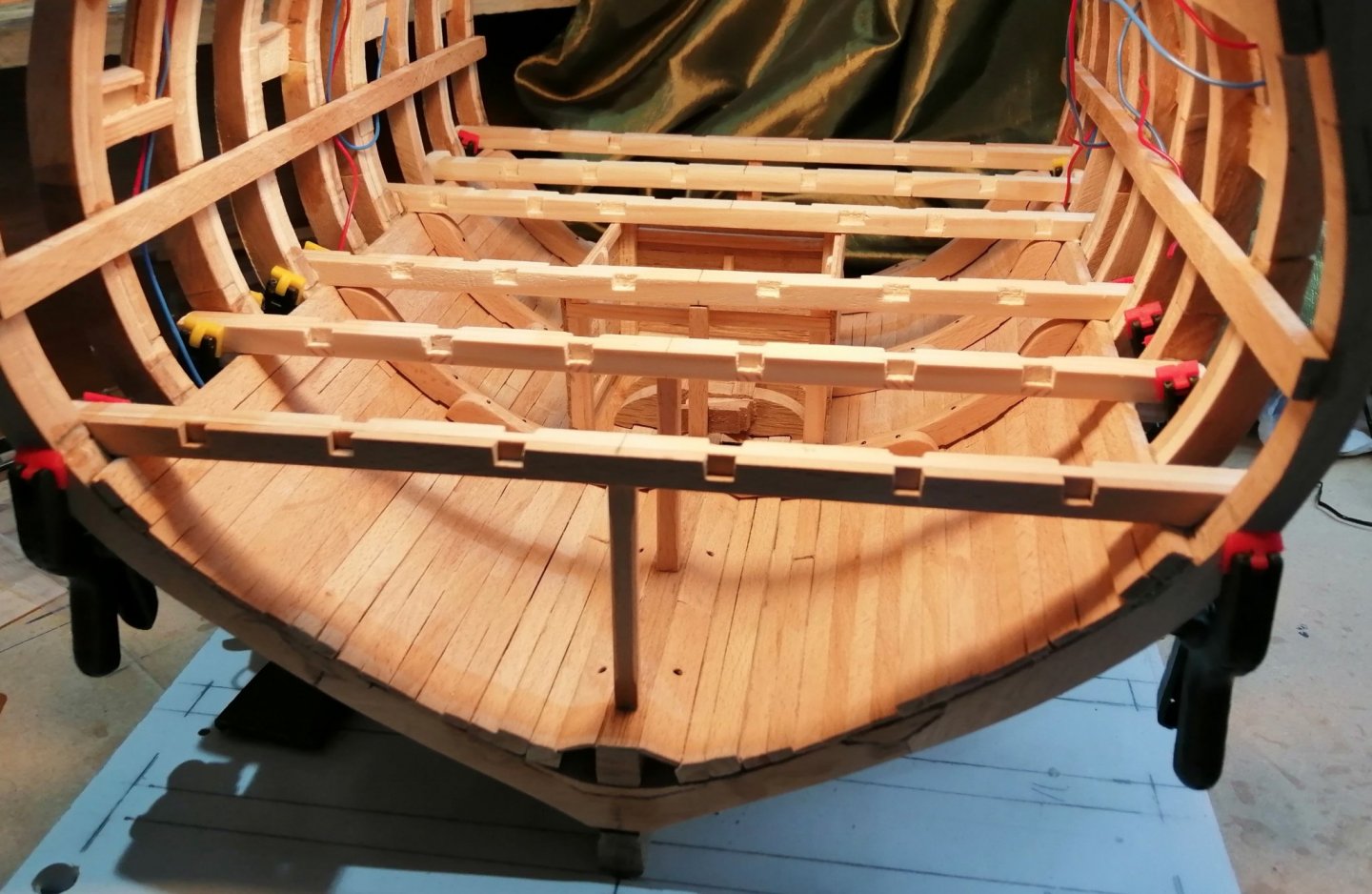
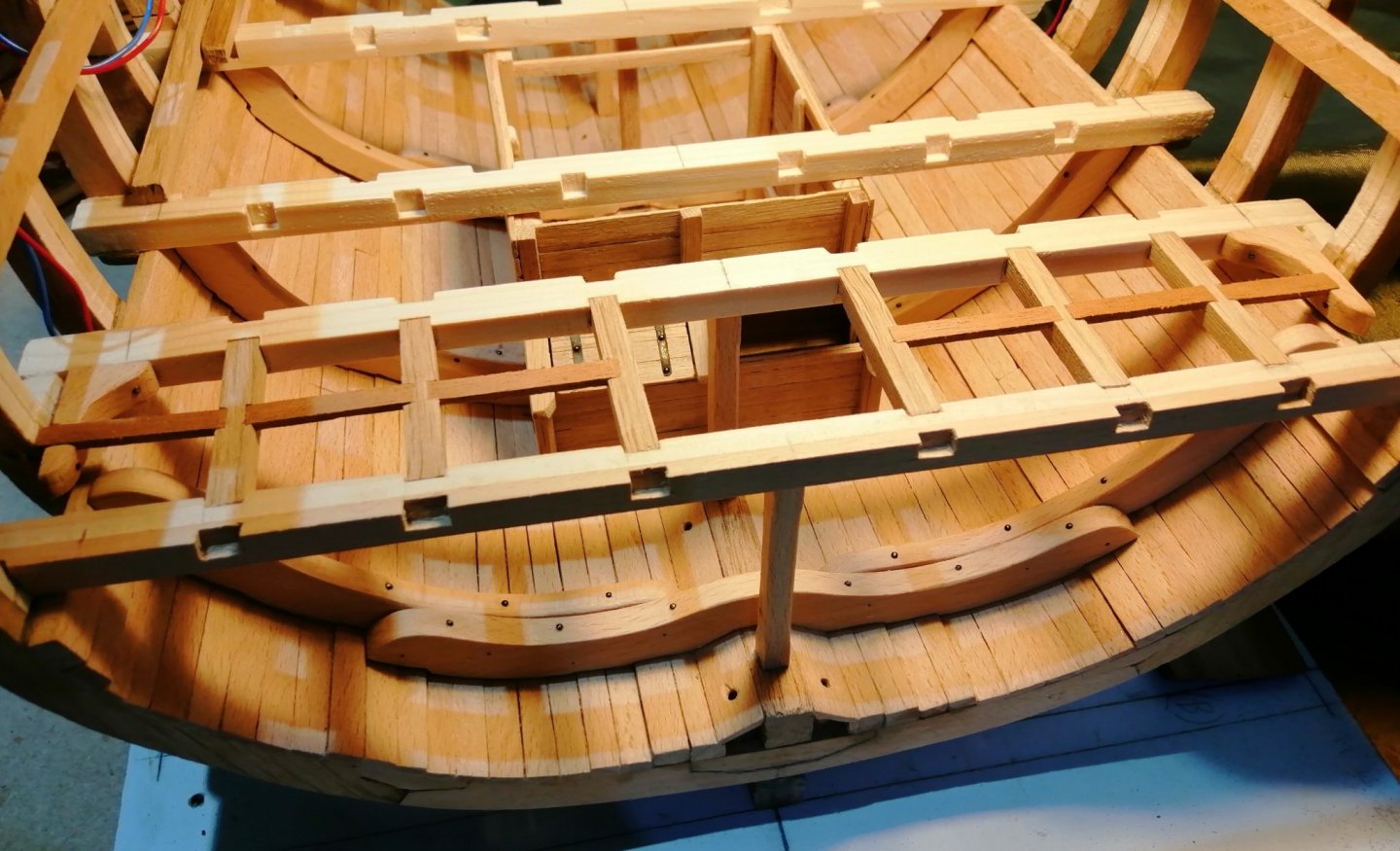
Time for something different - - time for a walk . . . a carpenter's walk. Of all the build logs I've looked at, I can't remember seeing any which have included the carpenter's walk, so I wanted to have a go at including at least part of one. Building a section as big as this has advantages and disadvantages. One of the disadvantages is that, although much more 'stuff' can be included, some of that 'stuff' could be obscured from view by other items. For that reason, one item I have decided to omit is the mid-ships sail room. In the same area where that sail room would be is the aft end of the carpenter's walk and cable tier and to include these would just be an added feature rather than creating a 'blind spot.' From this drawing I can see that I will be able to include one and a half sections of the lattice-work partitions that make up the carpenter's walk. I've outlined the two sections in red. > Just these two small parts involve 96 half-laps, so time to recruit the mill again. I used strips of beech in the dimensions of 4mm X 2mm and used a 2mm cutter to mill the 4mm wide half laps. In order to cut the half laps I spot glued two batches of strips to pieces of 6mm plywood. The strips were glued as shown in the following > That allowed me to make the cuts in groups of 4 as there are 4 half lap joints vertically and horizontally in each section. The 2mm cutter also took care of the vertical groove in the posts. . . . and cut closer to their final lengths. Trimmed and assembled. . . . and with the white stuff. First 'test ride' before the white stuff. With a few of the cable tier pillars and ventilation beams. The upper well and the blanks of the lower gun deck beams sitting in position (dry fitted) >


- 66 replies
-
- 13
-
-
Hi Tom, I have to say I've also wondered about that ~ but I don't have an answer. There may be someone who lurks around the Masting, Rigging and Sails forum who may have an idea. It might be helpful if you posted there.
-
Hi Gary, I just typed something like "profile tool" or "profile gauge" into Google and a whole host of these gauges came up. I just selected one from a local supplier -- Toolstation here in the U.K. I don't know if you're in the U.S. or Australia or wherever but I'm sure you shouldn't have much trouble in finding something. Here's a short video showing one in use. I'm not advertising or advocating this one -- it was just the first video that came up when I 'Googled' it.
-
Tom, You're right about all the stuff that isn't normally seen in a full model. I'm finding this is very educational as I'm having to do more research and asking questions for information that I didn't do on my previous full ship model. Another advantage is that I'm able to build at a much bigger scale so the 'smaller details' are correspondingly easier to work . . . although even at this scale some things are still quite tricky! JIm.
-
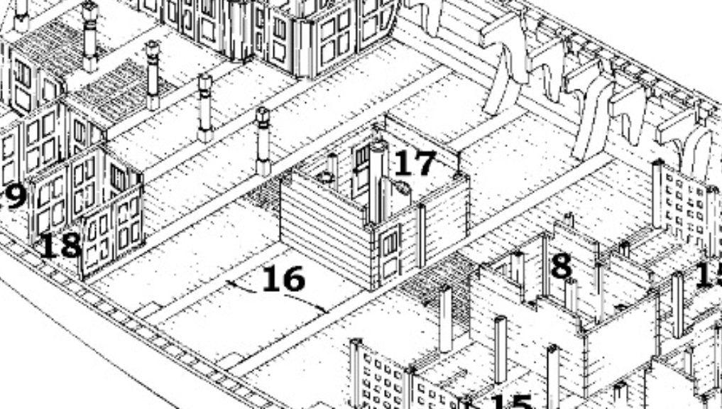
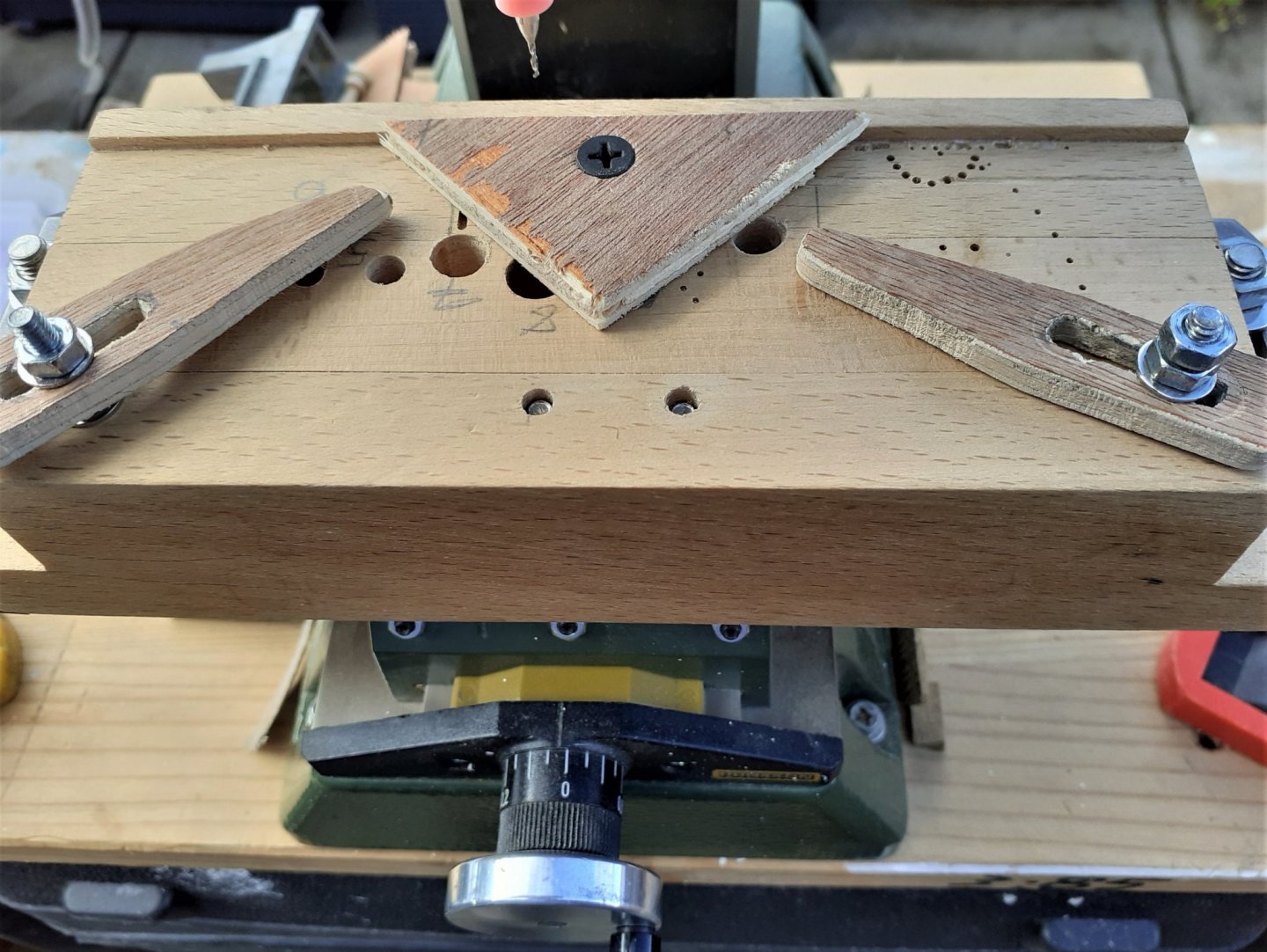
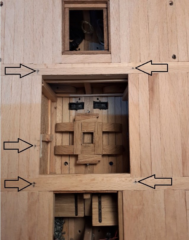
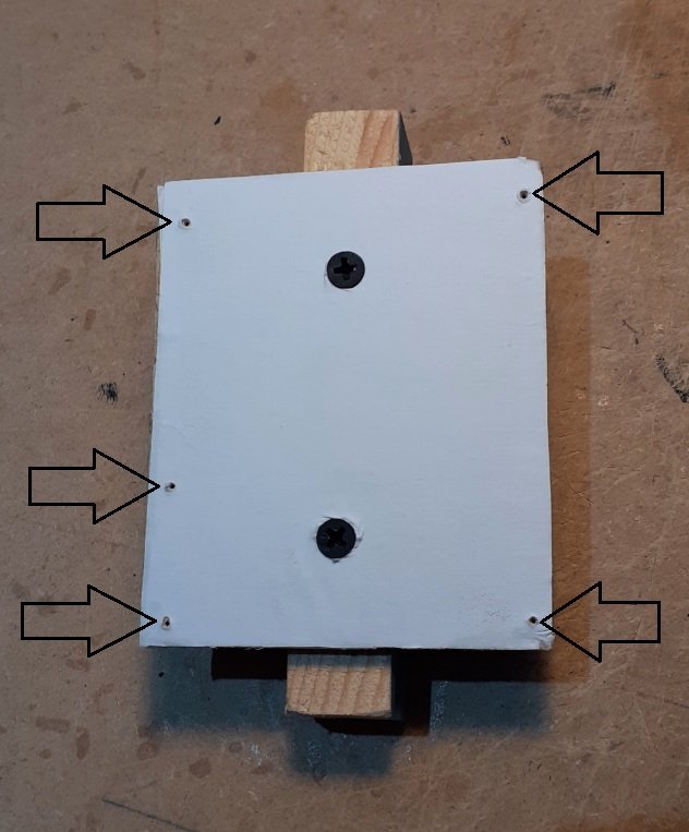
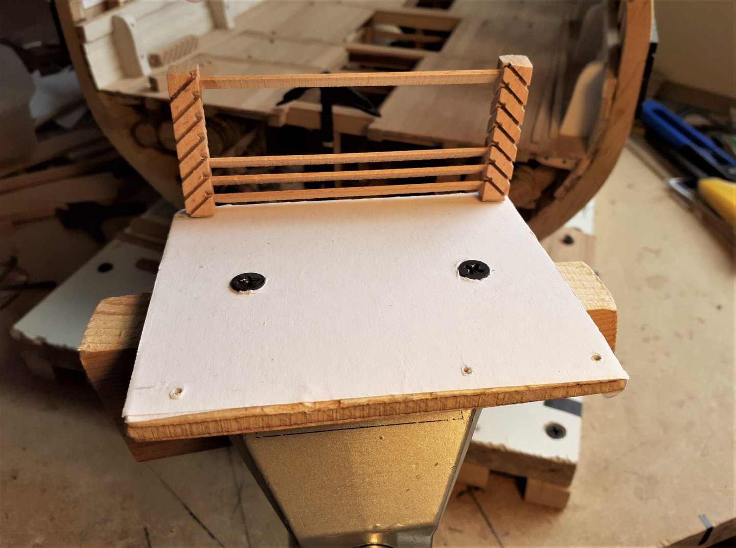
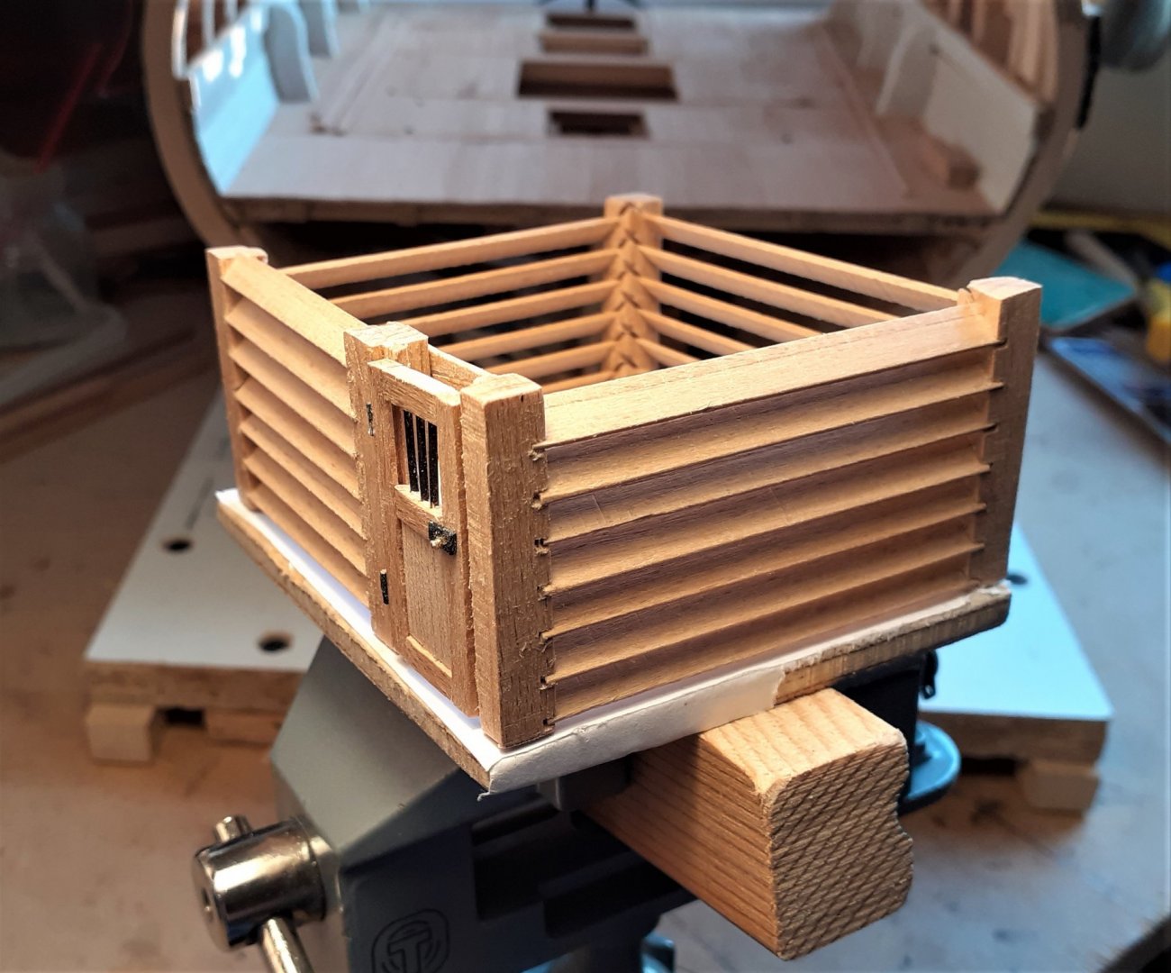
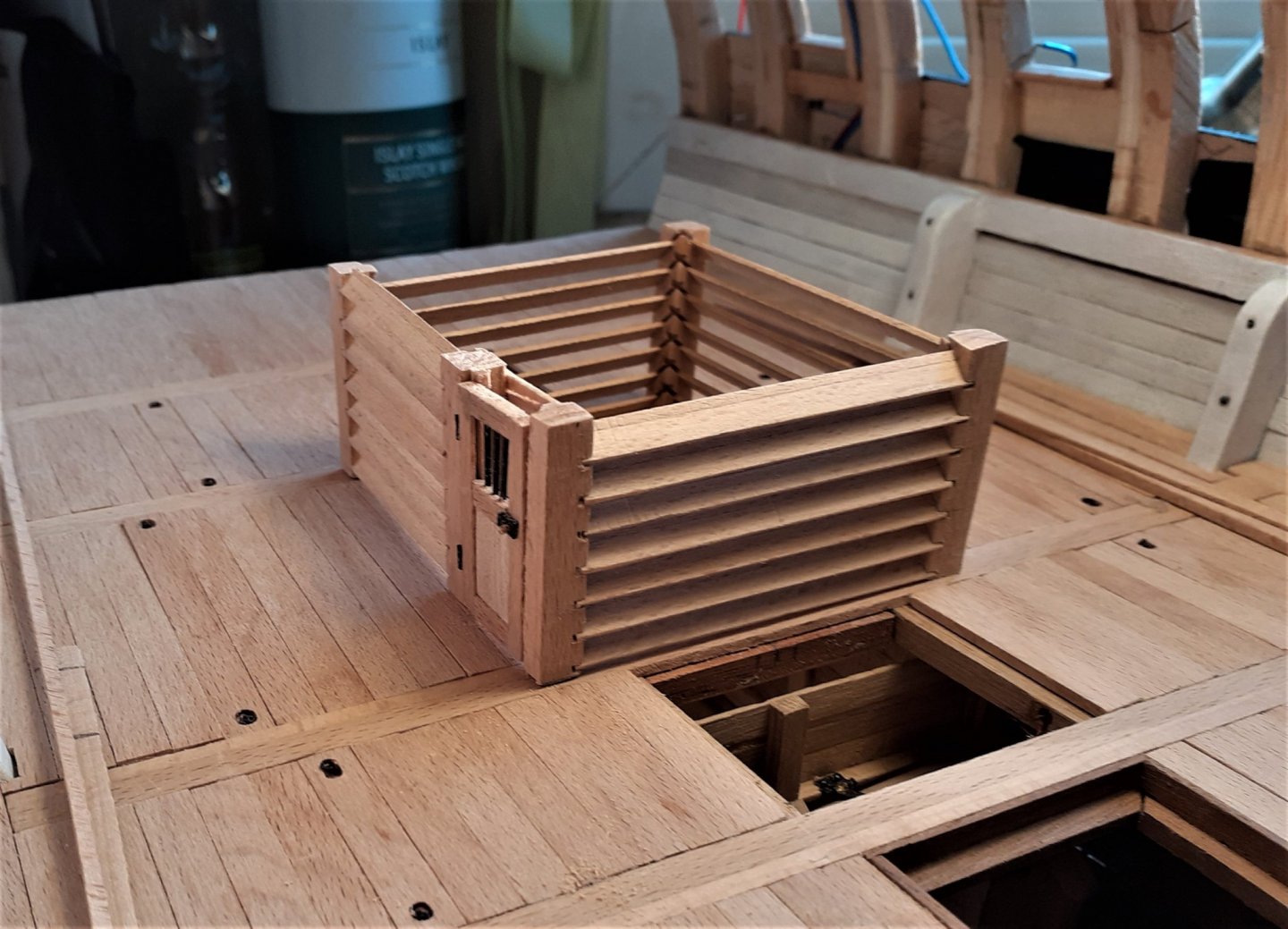
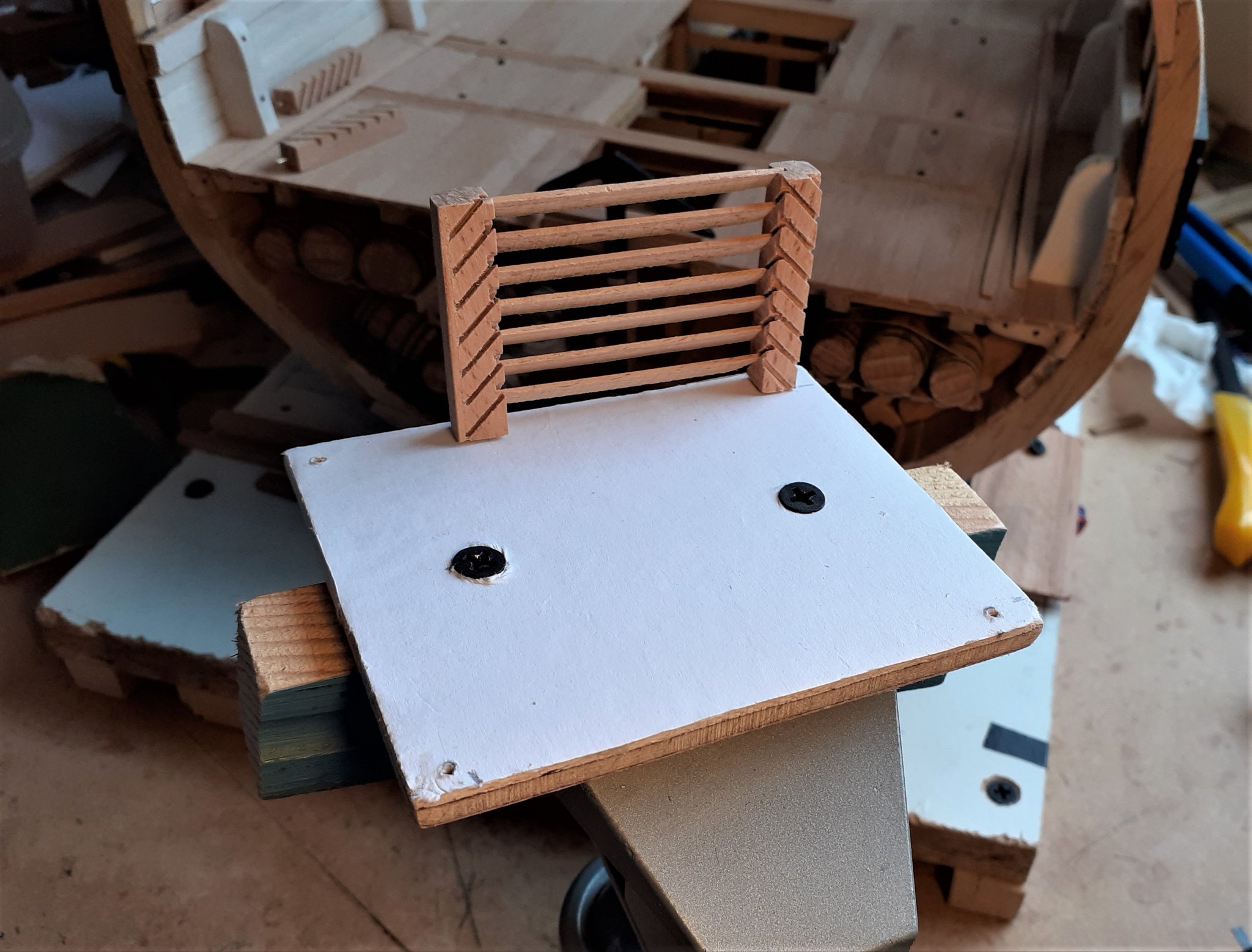
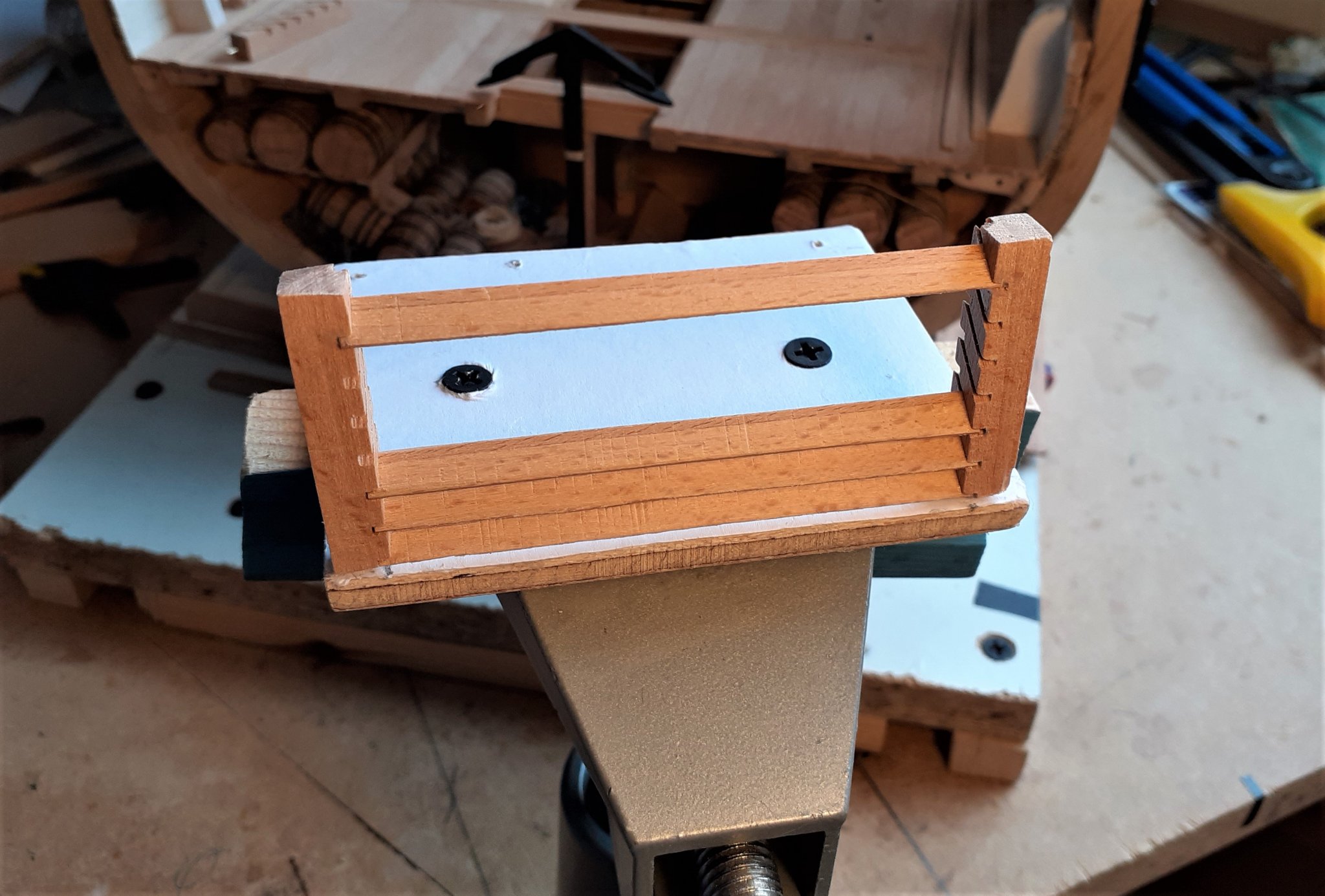
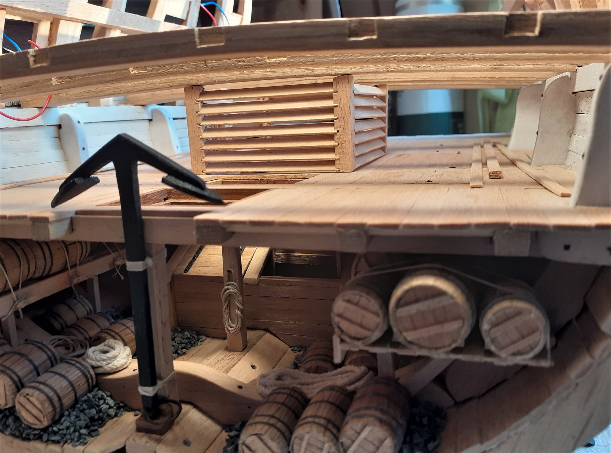
Thanks for the likes and visits. Now that the beams were established in their positions (although not yet secured) the dimensions of everything to be placed on the orlop deck could also be established. Decided to start with the upper well and the first little challenge was to decide what format it would take. I say that as there is a bit of a conflict between the only two drawings I have of that structure. In the schematic drawing it looks like this > In the above drawing the upper well (#17) appears with a door on the front as well as a door on the rear, also the planking appears to be 'conventionally' flat. Here's the other image I have > In that image, which is viewed looking towards the stern, there is no door on the front of the upper well (#9) and it's not clear from that whether the boards are flat or louvred. On several build logs of ships from a similar period I see the builders have made louvred walls, so following these as a fairly reliable lead I opted to take that route. New challenge. I've never done louvres before, not even on full-size projects. Out came the milling machine again. On a previously used jig I screwed on this simple triangle against which the posts could be secured and slotted > The opposite angled slots would be cut on the other side (right-hand side) of the triangle. I soon realised that if both 45 degree angles weren't exactly equal there would be a visible discrepancy in the finished slots, so I did all the left-hand cuts first then unscrewed and flipped the triangle round before cutting the right-hand cuts. The first post > I made all of the 5 posts in over-long lengths as that made getting them all cut to their exact finished lengths a bit easier. I inserted a piece of 1mm brass wire in the centre of each post/pillar to facilitate correct positioning on the deck. > All 5 posts in position > In line with what I saw on other builds, I opted to place one door on the starboard side. It seemed to me that it would have been quite tricky to have tried to glue in all the slats with the posts in their positions on the deck, so time for another little jig. The following pic shows the 5 holes for the brass pins > I held a piece of paper over the deck while piercing holes to correspond with the drilled holes in the deck. I cut the paper down to size and glued it on to a piece of 6mm plywood and attached that to a strip of wood so that it could be held in the vice. > First 'short wall' done > I found the best way was to insert the bottom slat first, then the top one. Doing that helped ensure that the posts would remain parallel to each other while fitting the other slats. > Then, quicker than I was expecting, it was complete. It wasn't nearly as challenging as I thought it would be. Then on board >


- 66 replies
-
- 14
-
-
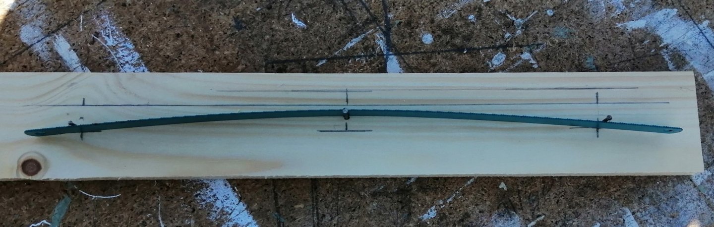
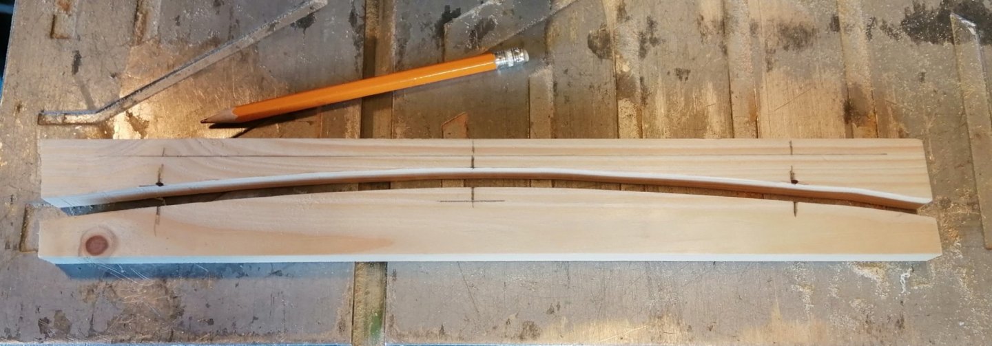
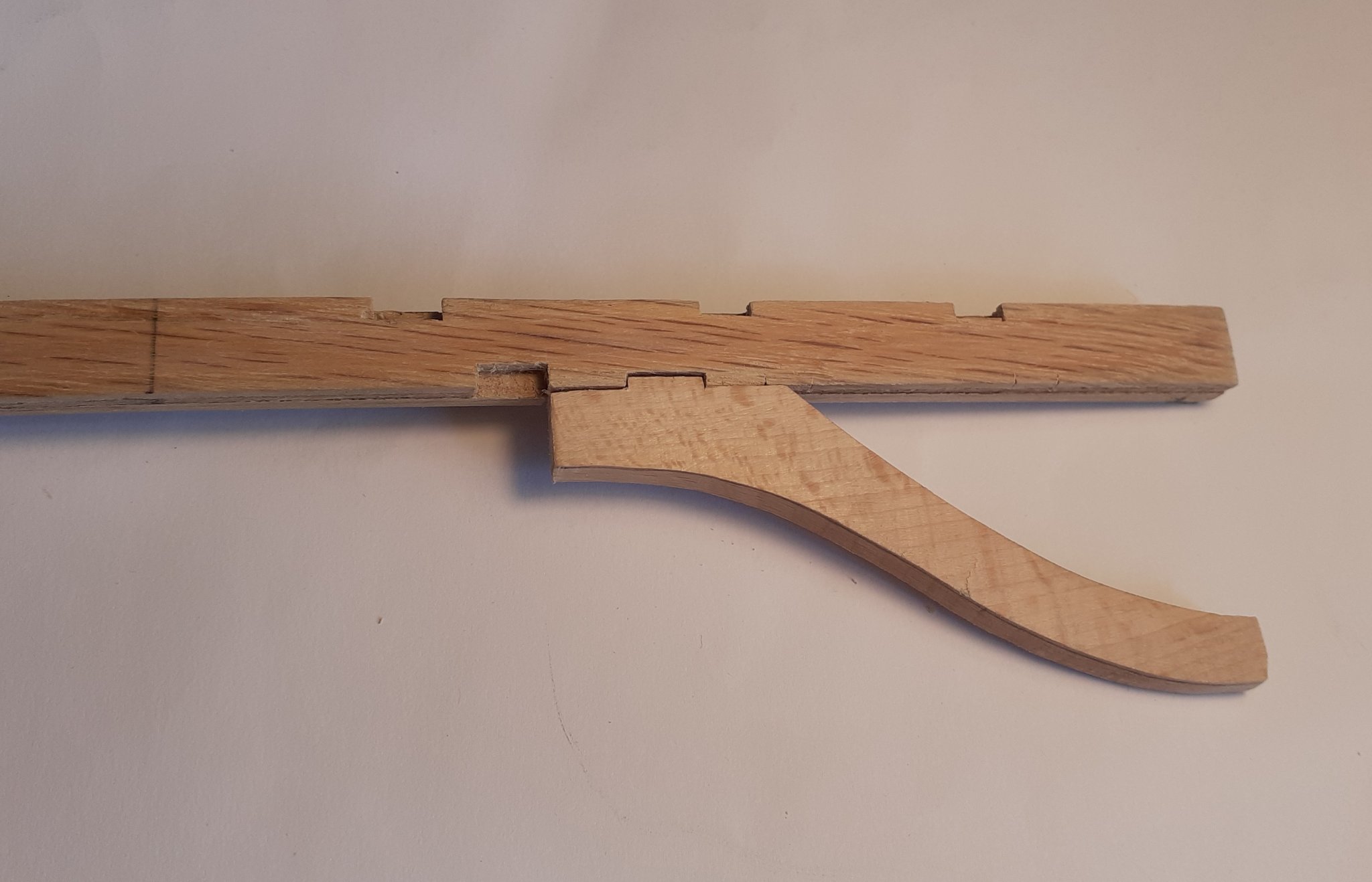
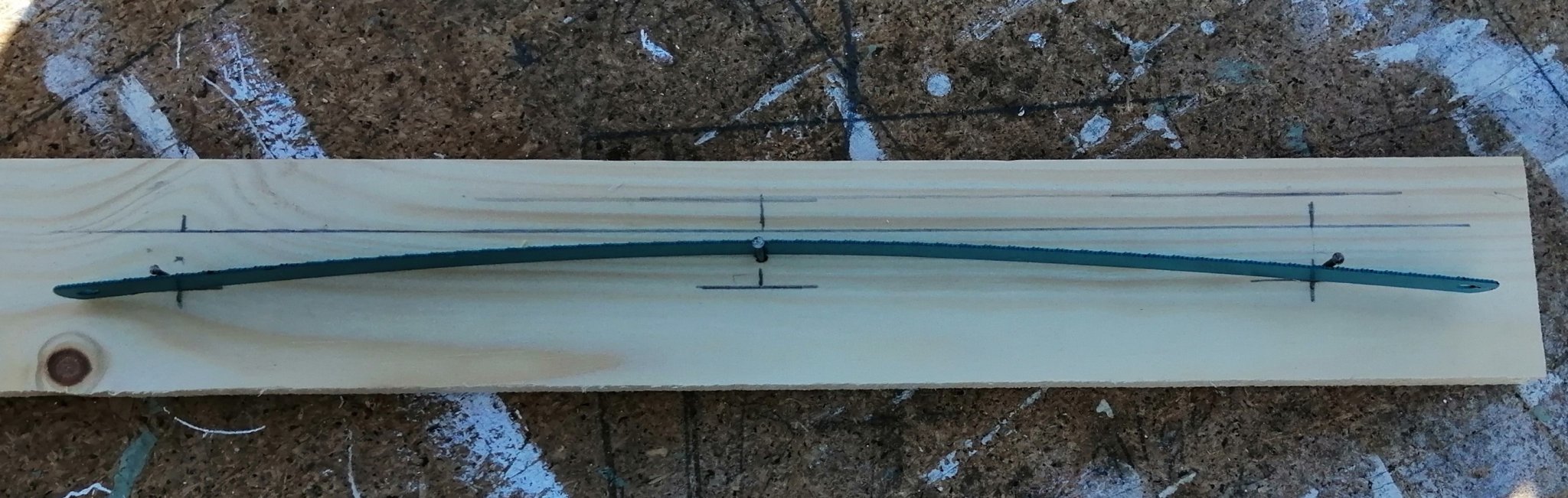
Back inside the ship I wanted to be getting some of the structures for the orlop deck made but in order to establish the height of these I needed to have the lower gun deck beams to be at least temporarily in place. In my previous build I had found it a little tricky trying to get a constant curve on every beam so I decided I would use 4 thin strips to laminate each beam. I made a former out of a piece of softwood. I used the 'hacksaw blade and 3 nails' system to achieve the curve. I decided on the curve I wanted, knocked in 3 nails - one at each end and the third in the centre and bent the hacksaw blade in place and drew the curve. The following photo may explain it better > Cut the curve at the bandsaw and lightly sanded both parts of the curve. The first beam out of the former > The laminated appearance diminishes somewhat after sanding the sides and the sides and undersides of the beams will all be painted with the 'white stuff' as well. From my previous experience of laminating strips of wood into a curve I knew that the wood naturally 'springs back' a little from the shape of the former, so when drawing the curve I set it a little 'higher' than I wanted. Well, this wood had other ideas! -- it just stayed exactly as it came out of the former and looked just a bit too extreme in its curvature. So, a few hours clamped on to a flat surface and the six beams were more 'normal looking'. Placed in position > At this point I discovered a bit of a minor horror. I'm a long-time member of the "measure twice, cut once club" and always take great care to follow that rule before committing a knife or saw to a workpiece - or in this case, before committing a part to the glue. I'm still mystified as to how I did it -- but somehow the port side lower gun deck clamp was about 1.5mm higher than was the starboard clamp. These clamps are 'welded' on with epoxy resin and I wasn't about to cause major devastation by trying to remove the offending clamp. Instead, I opted to notch a little material out of the underside of the port end of each beam. Beams now sitting as they should be. Now I'm scared to look for any other 'goof-ups' -- in case I find any!

-
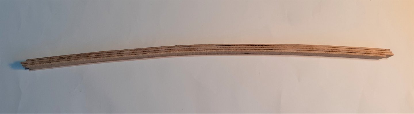
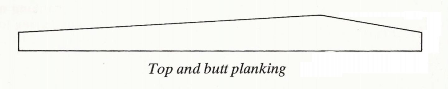
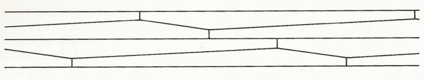
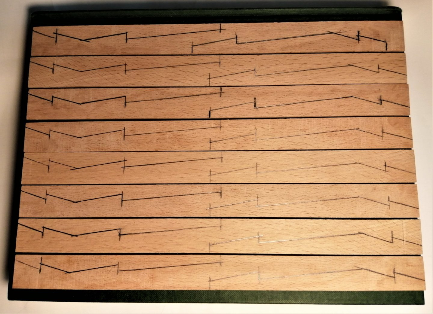
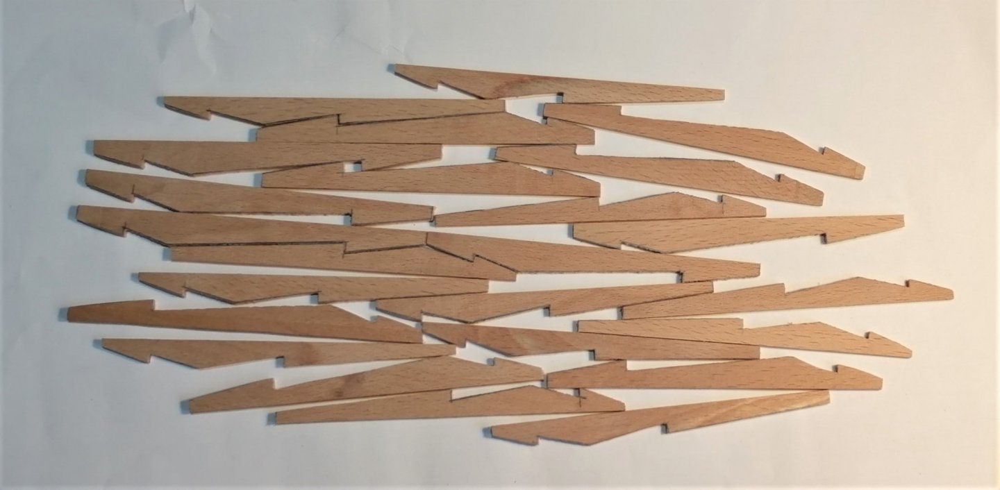
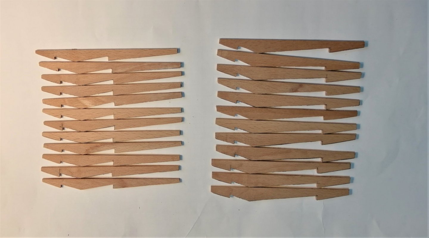
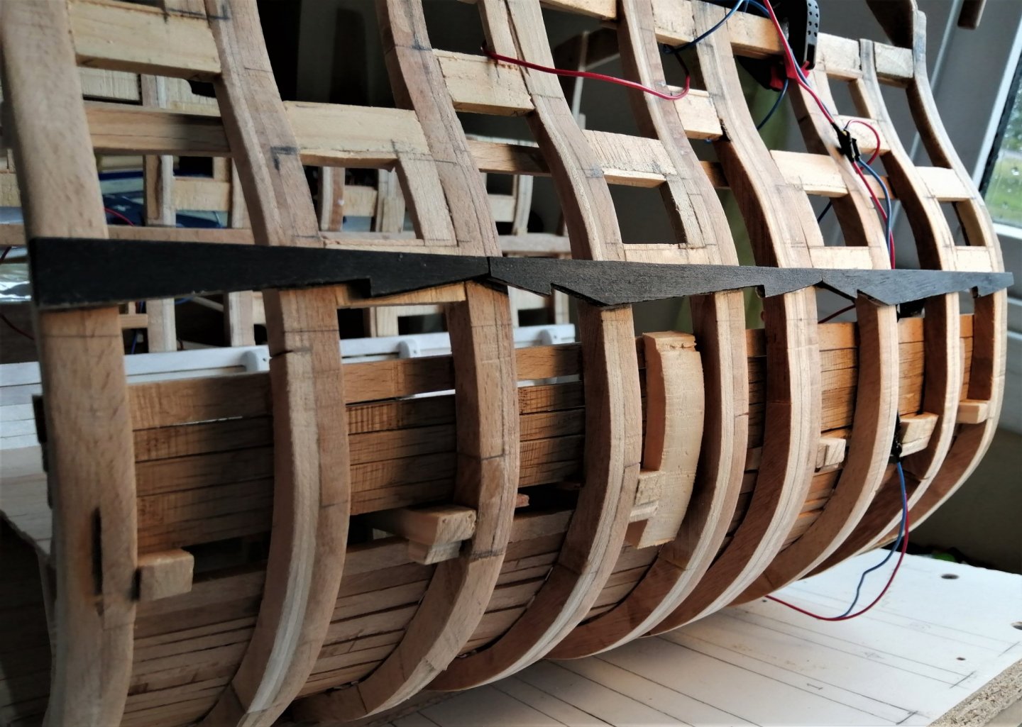
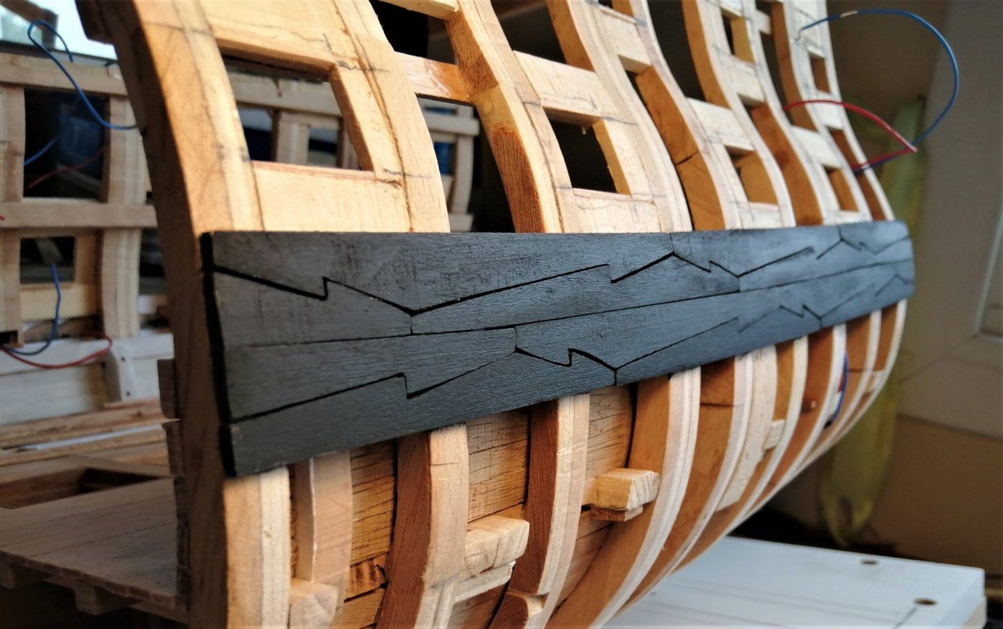
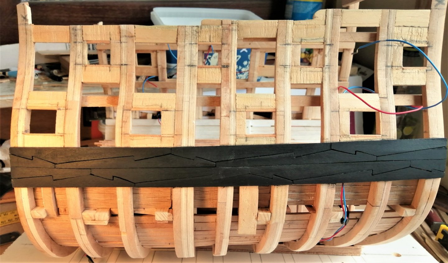
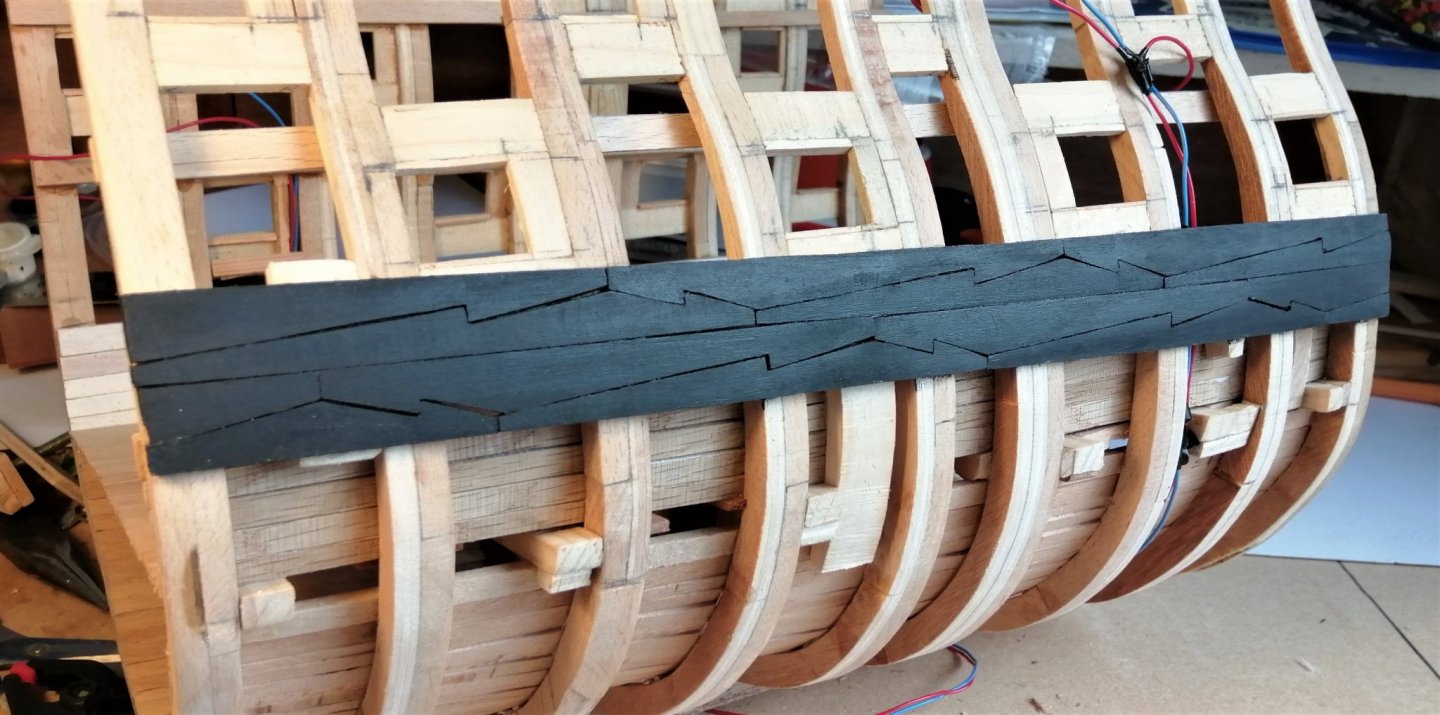
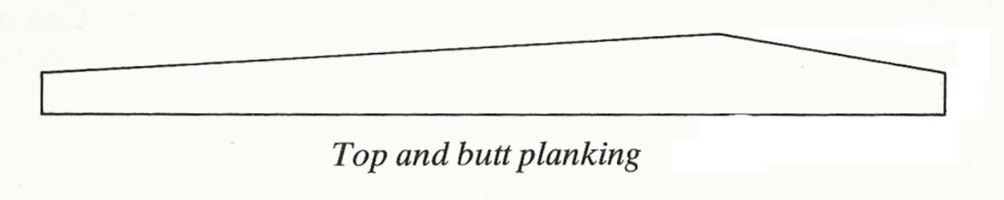
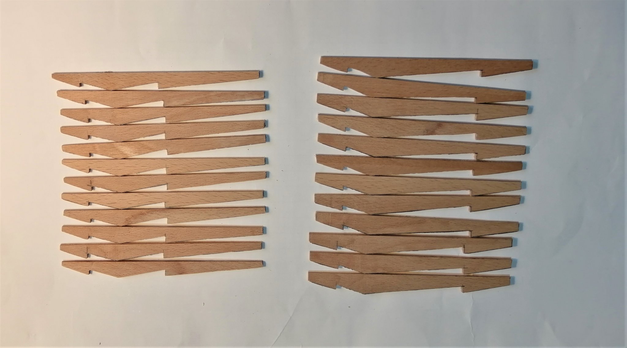
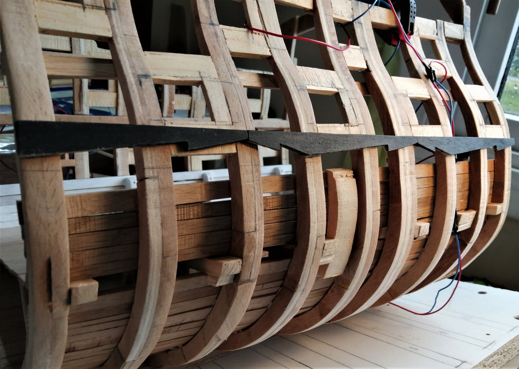
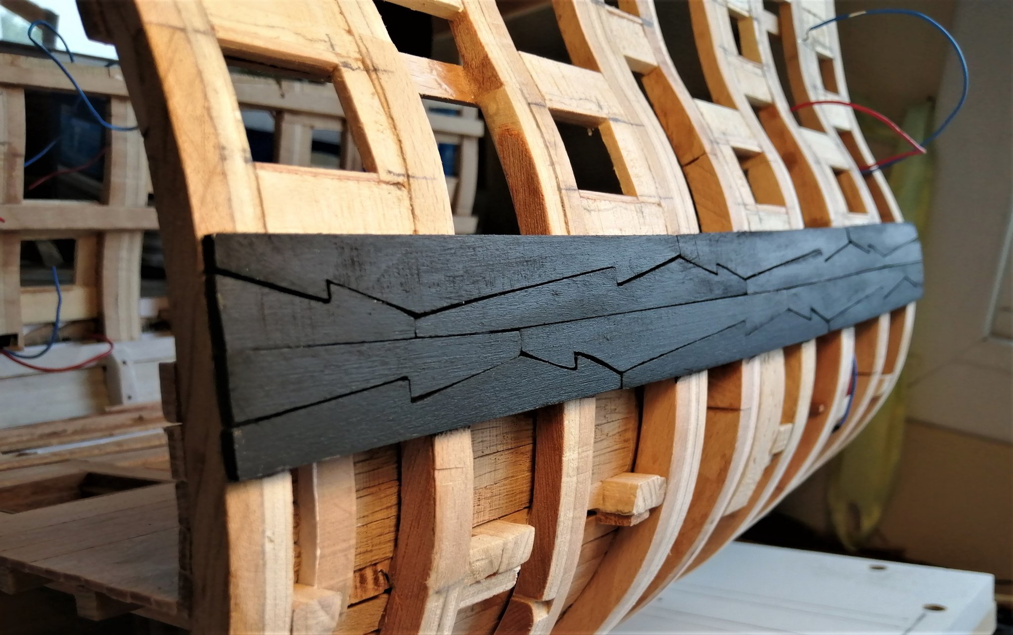
Thanks Tom, Michael and Havelock for the comments, and the others for the likes and visits. "Diversion update." As I said, I've left the hold for the present and decided to have a go at the wales. The wales could pretty much be done at almost any time in the build but because they're the tricky hook and butt planks I wanted to see how I would get on with them. In my other build the wales were hook and butt, but at about half of the scale of this one, I found them very difficult back then and eventually opted for the easier top and but planks like these > . . . and when on the ship, looked like this > What I was hoping for (on this build) was for the wales to look like this > On lots of build logs I've seen the use of metal templates to obtain the shape of wales planks. I did consider this method, but in the lack of suitable metal, and the thought that if the templates weren't completely accurate, then neither would be the wooden wales. So I opted to cut each one individually on the bandsaw. I reckoned I would need 24 planks so I made 28 "just in case". I hoped I wouldn't have to make any more than that. Here are 16 of the blanks. 24 of them after they had been to the bandsaw > And looking a little more orderly. I painted the planks before fitting them. Here, the first 3 "starter" planks in position > Port side > Starboard side > Now I can get back to something a little less tricky.
- 66 replies
-
- 12
-
-
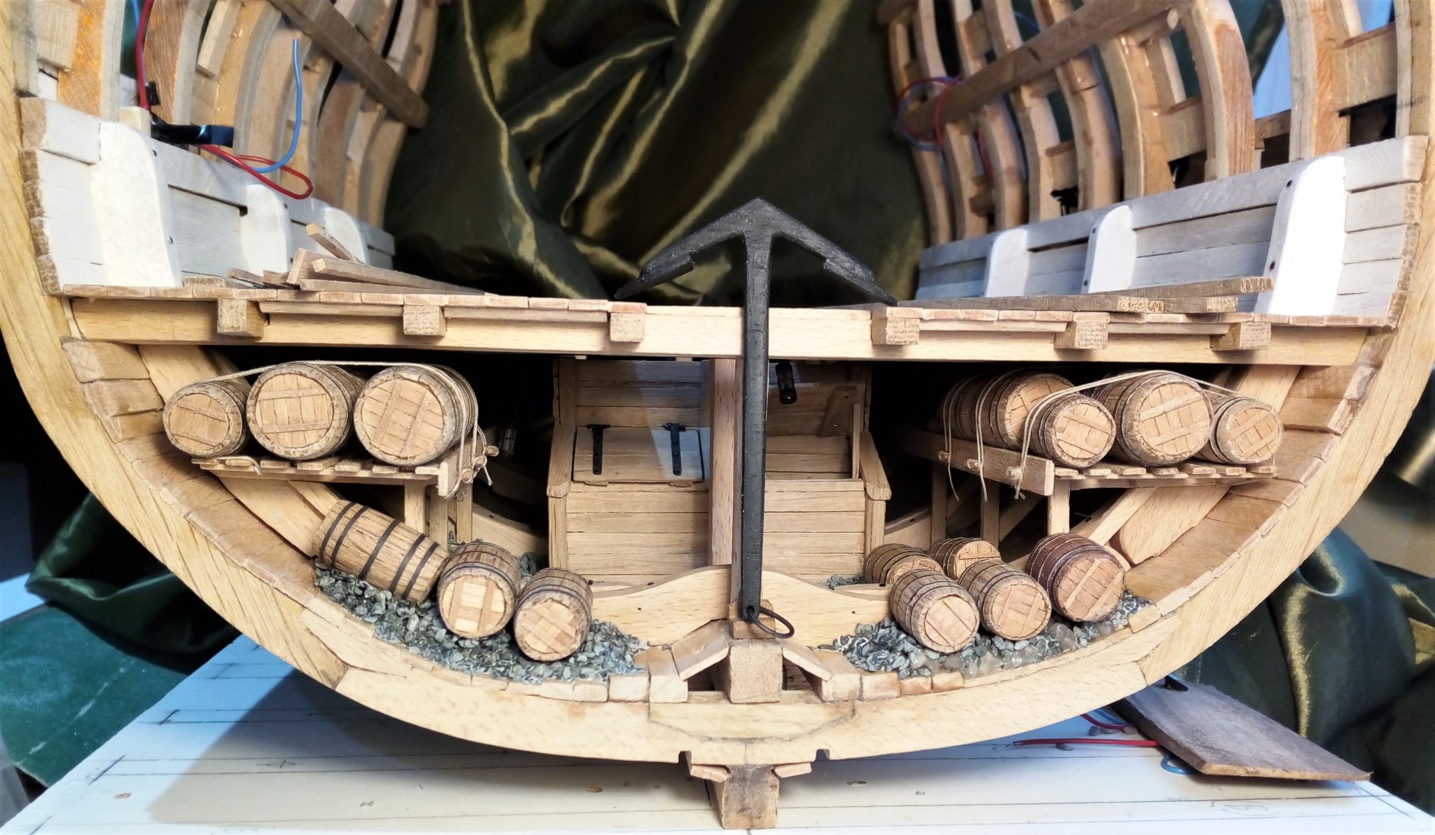
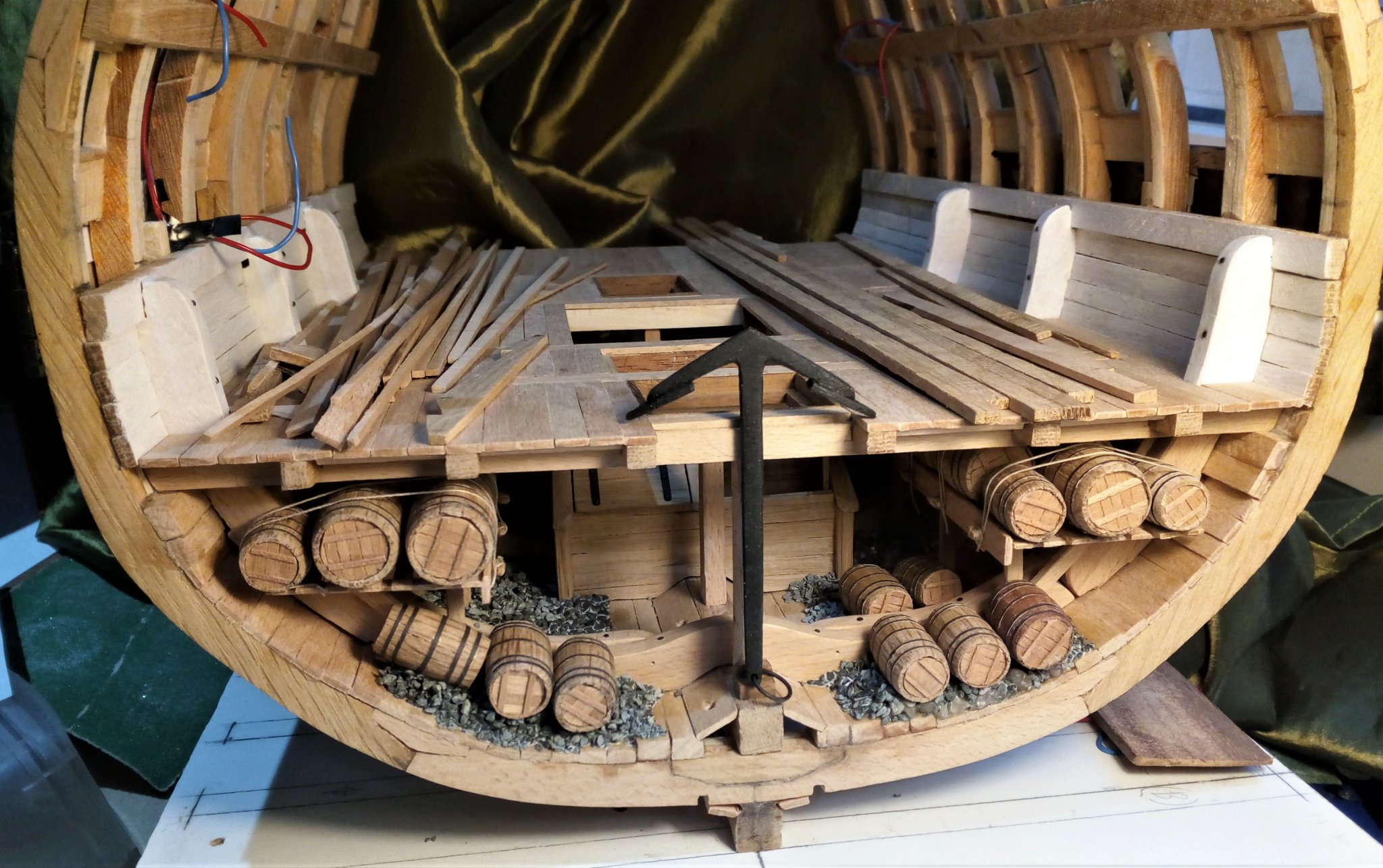
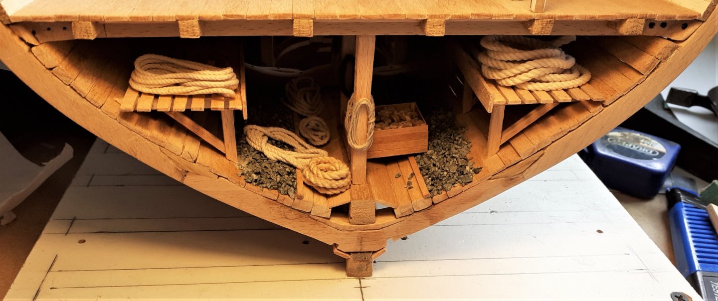
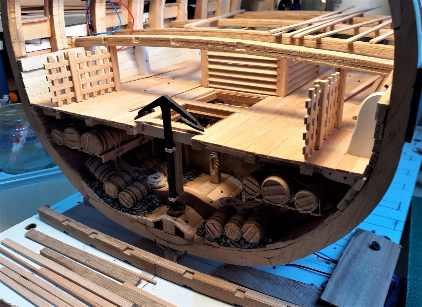
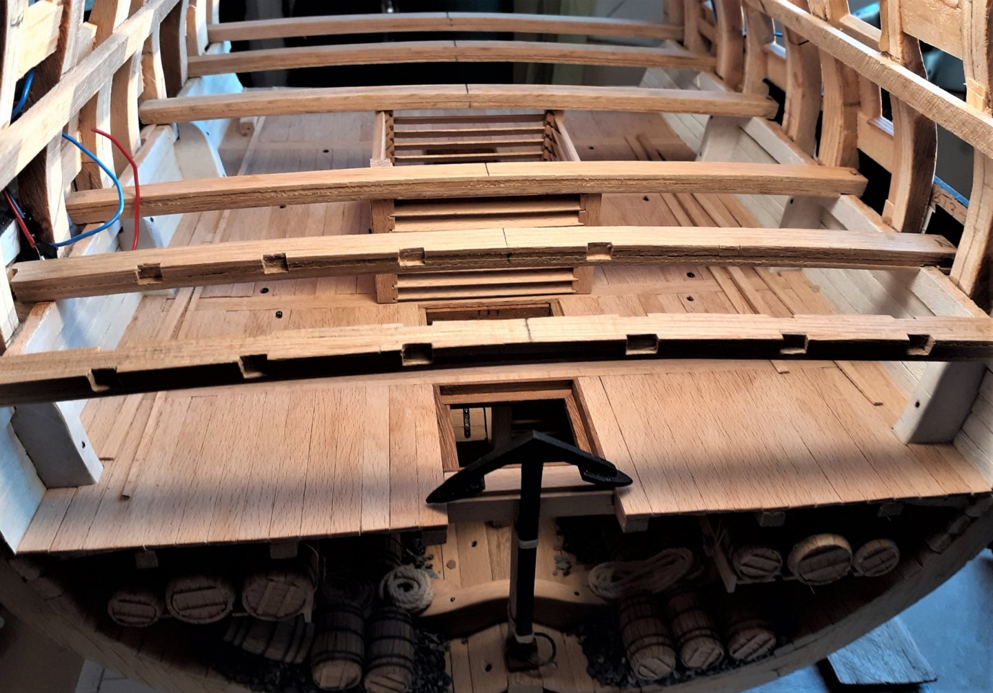
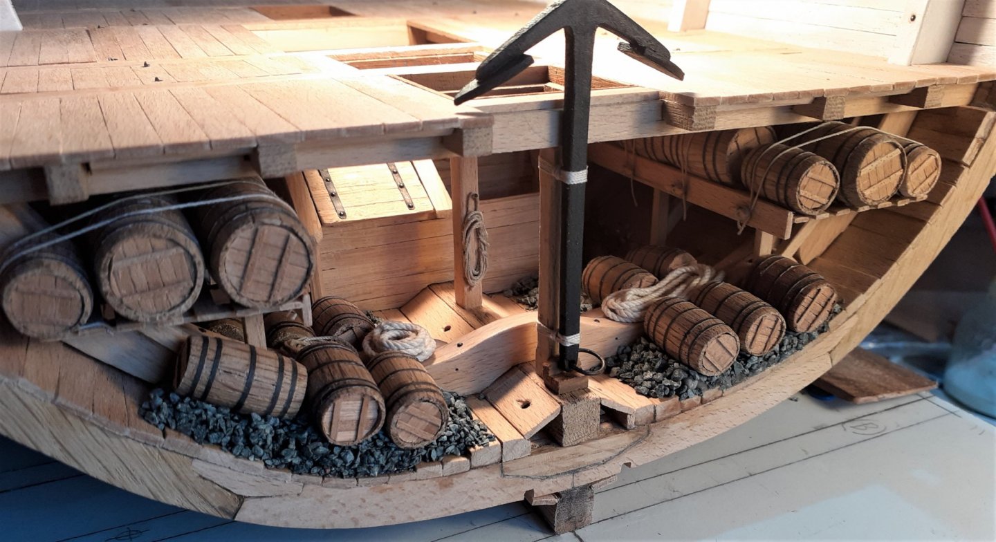
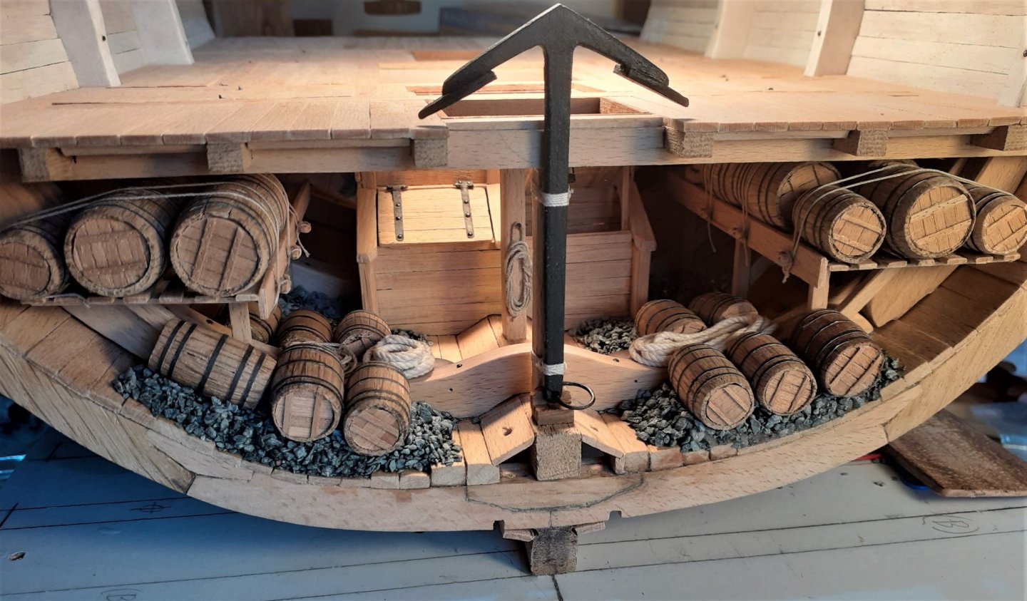
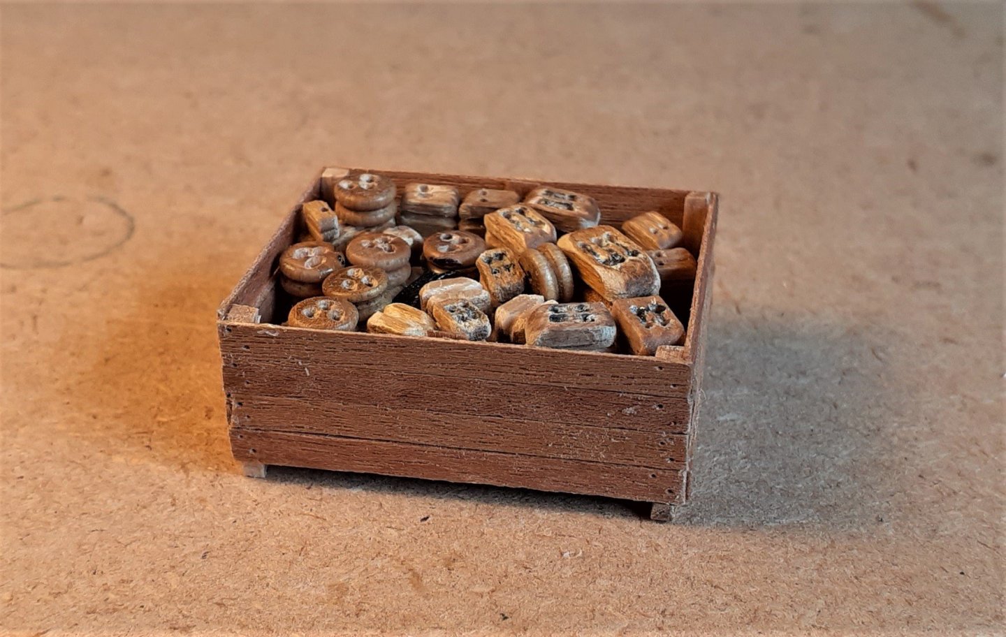
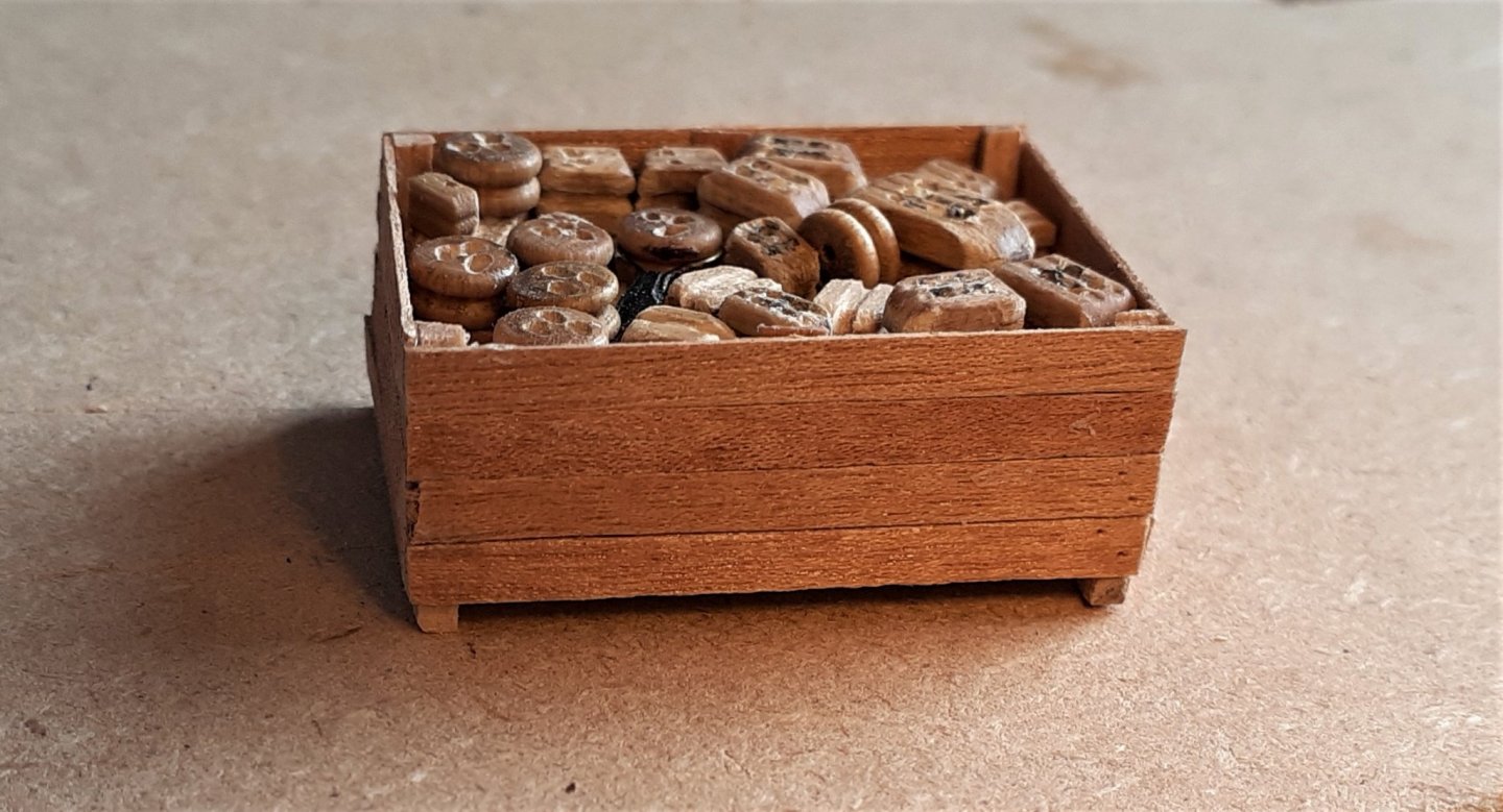
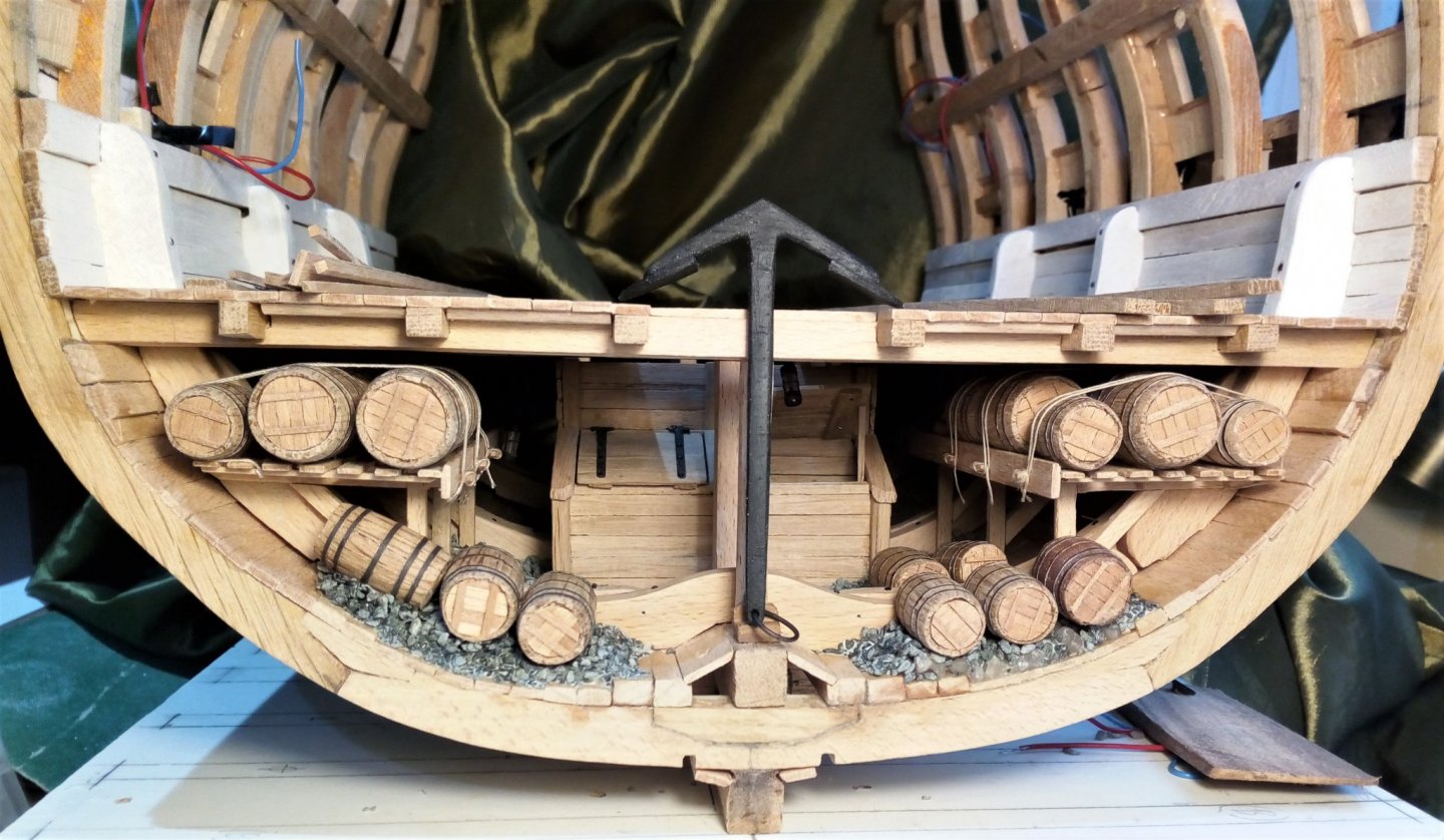
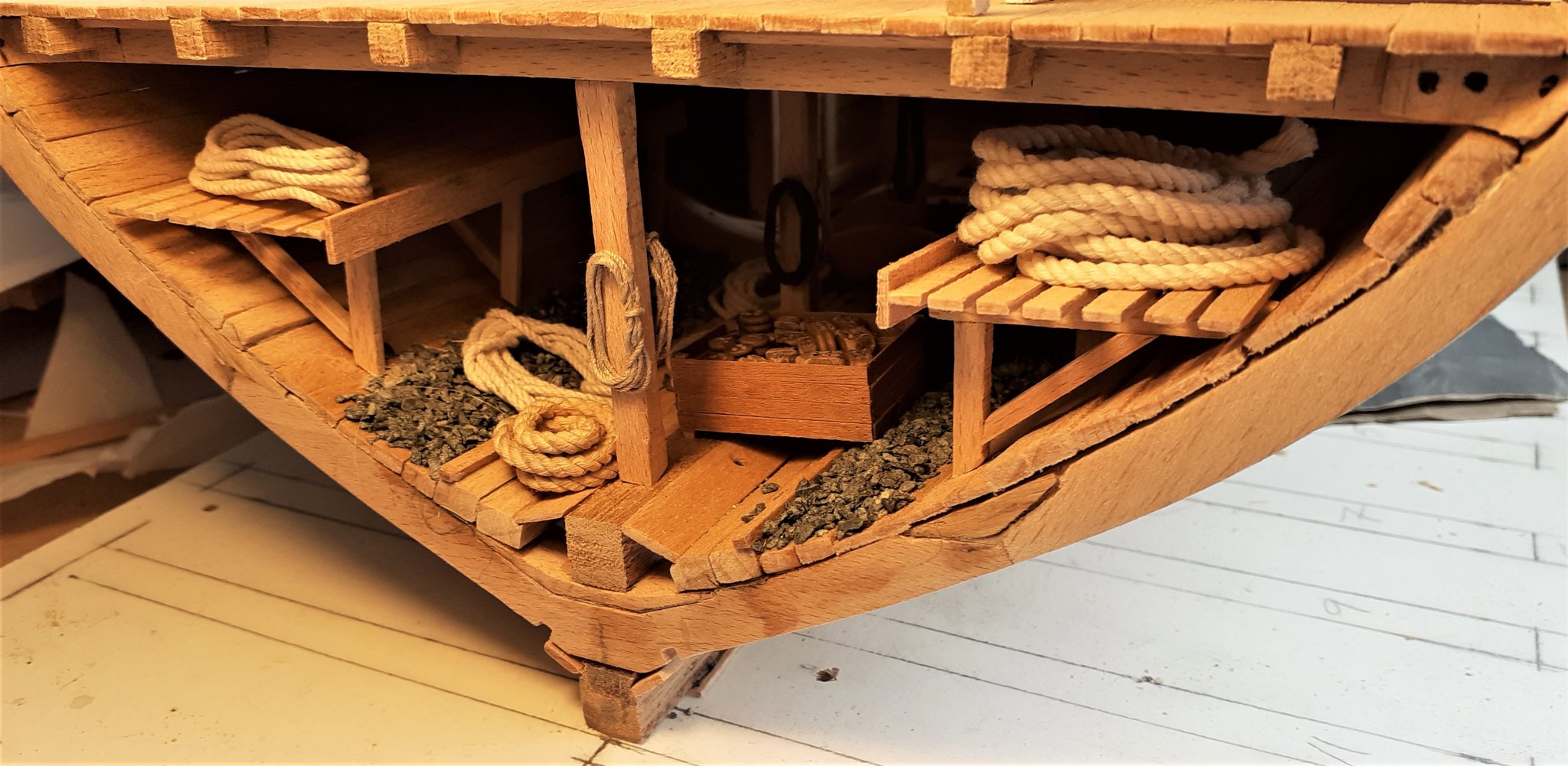
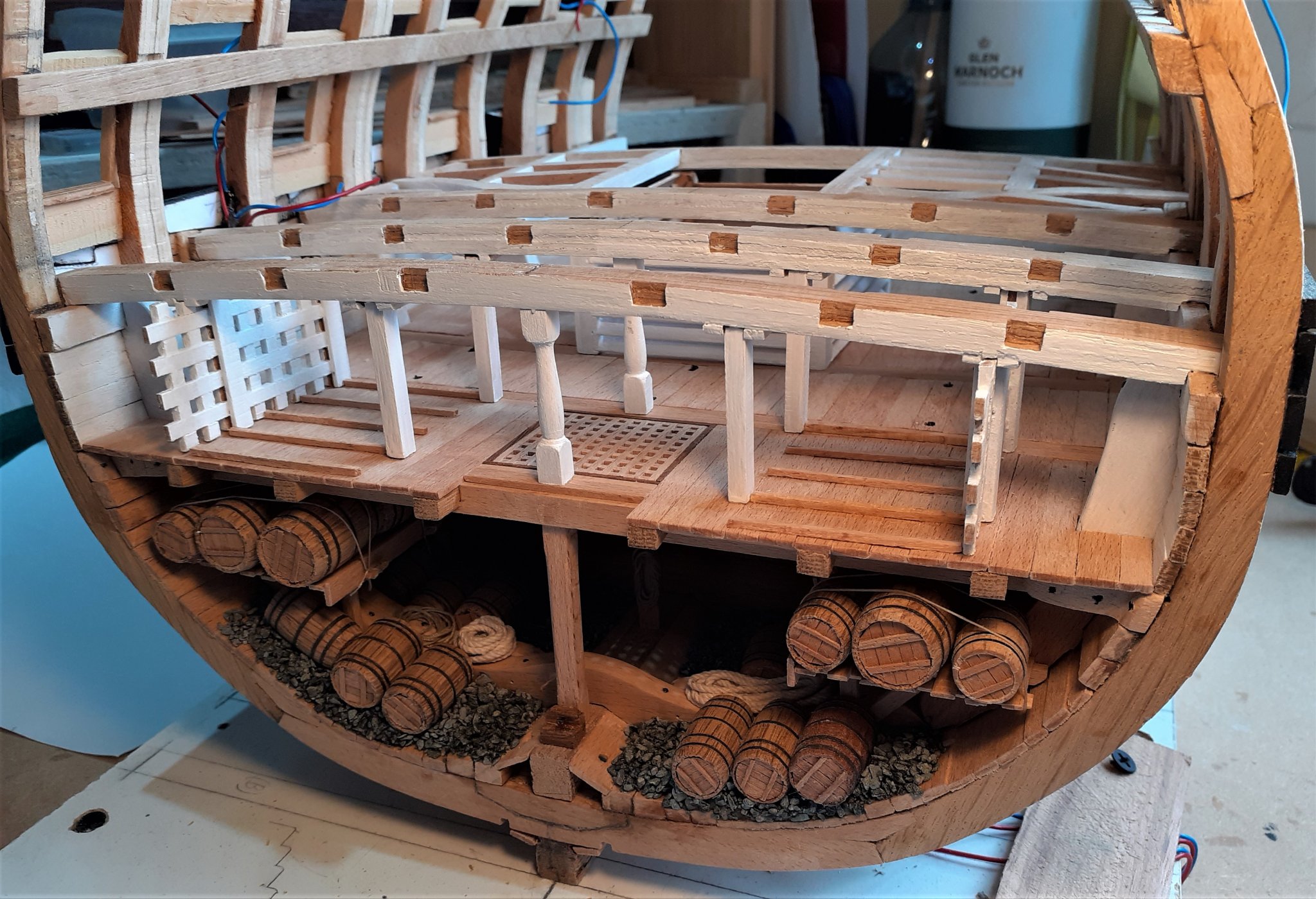
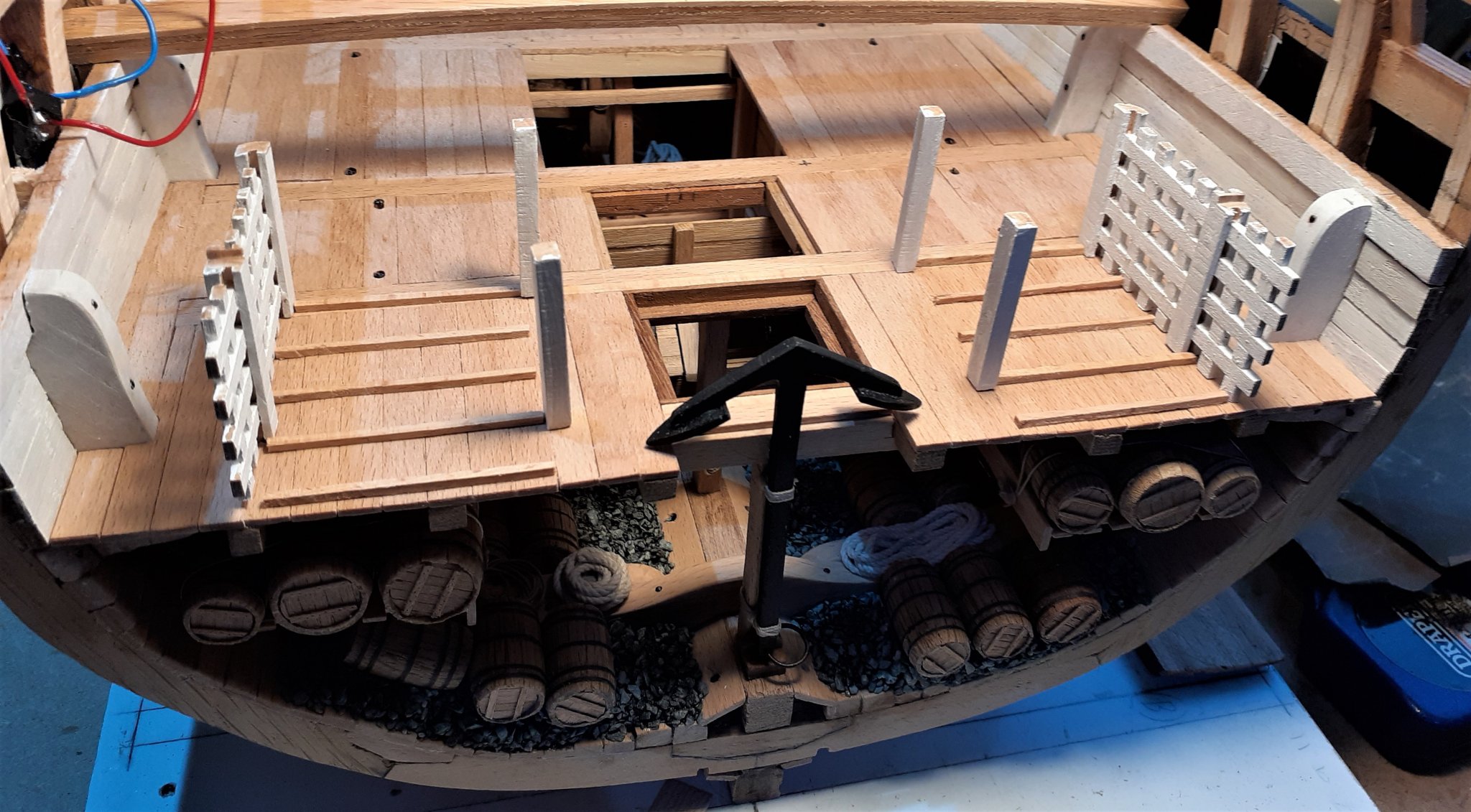
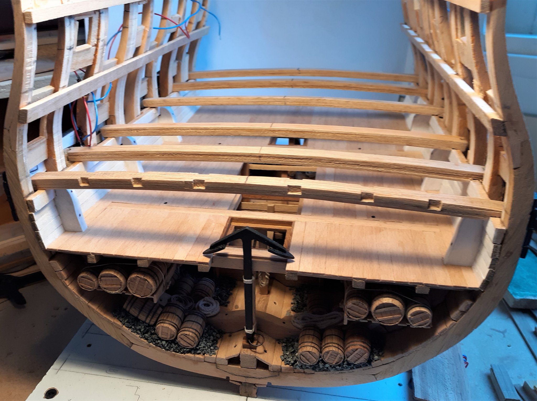
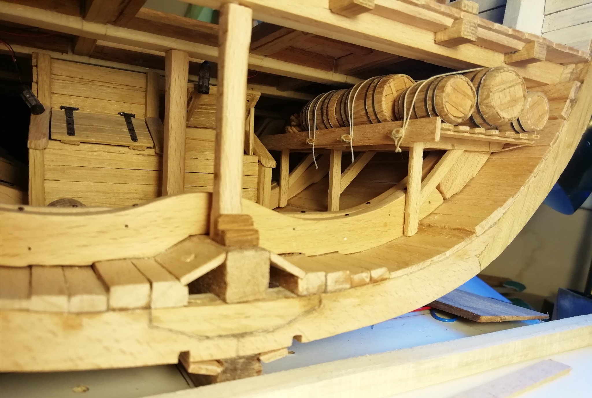
Thanks for the likes and for the visits. Not a lot to show in an update, but that doesn't mean that there hasn't been a lot of time spent preparing all these little things. Finished adding barrels to the fore end of the section, added more ballast, the anchor is now lashed on to the pillar and a few lengths of rope added. I didn't want to 'overcook' it with so many barrels that the view to the inside would be obscured. At this point the aft end of the section was still empty except for some ballast. I made an open-topped crate in which to put some blocks and dead eyes that I had left-over from the previous build. Most of these blocks and dead eyes were rejects from earlier as most of them looked awful with their holes all in the wrong places so I had to spend some time with them trying to get them to look a bit more 'real -- even if they're not really going to be seen when they're tucked away under the orlop deck. Right now, all I have in the aft end is that crate and an assortment of ropes of various gauges, some just on the deck and a few hanging on the pillars. Taking a break from the hold for a week or two to find a different project on or around the orlop. (I've put the hold "on hold".) The space in that aft part of the hold is roomy enough to come back to later when I've decided what to do with it.

.thumb.jpg.bc45c0bb77090fb7507c5cf37f983d77.jpg)
- 66 replies
-
- 11
-
-
Looking great Tom! . . . and I know it's a great feeling to get to that stage. (and I won't spoil it by mentioning the topmast ratlines. I did say I wouldn't mention that, didn't I?) Now, if I can help you with some arithmetic here: Number of ratlines versus number of yards - - - Ratlines = 1,392; Yards = 21 That's assuming you're stopping at topgallants and not doing Royals, and making yards is much more fun AND much easier on the brain!
-
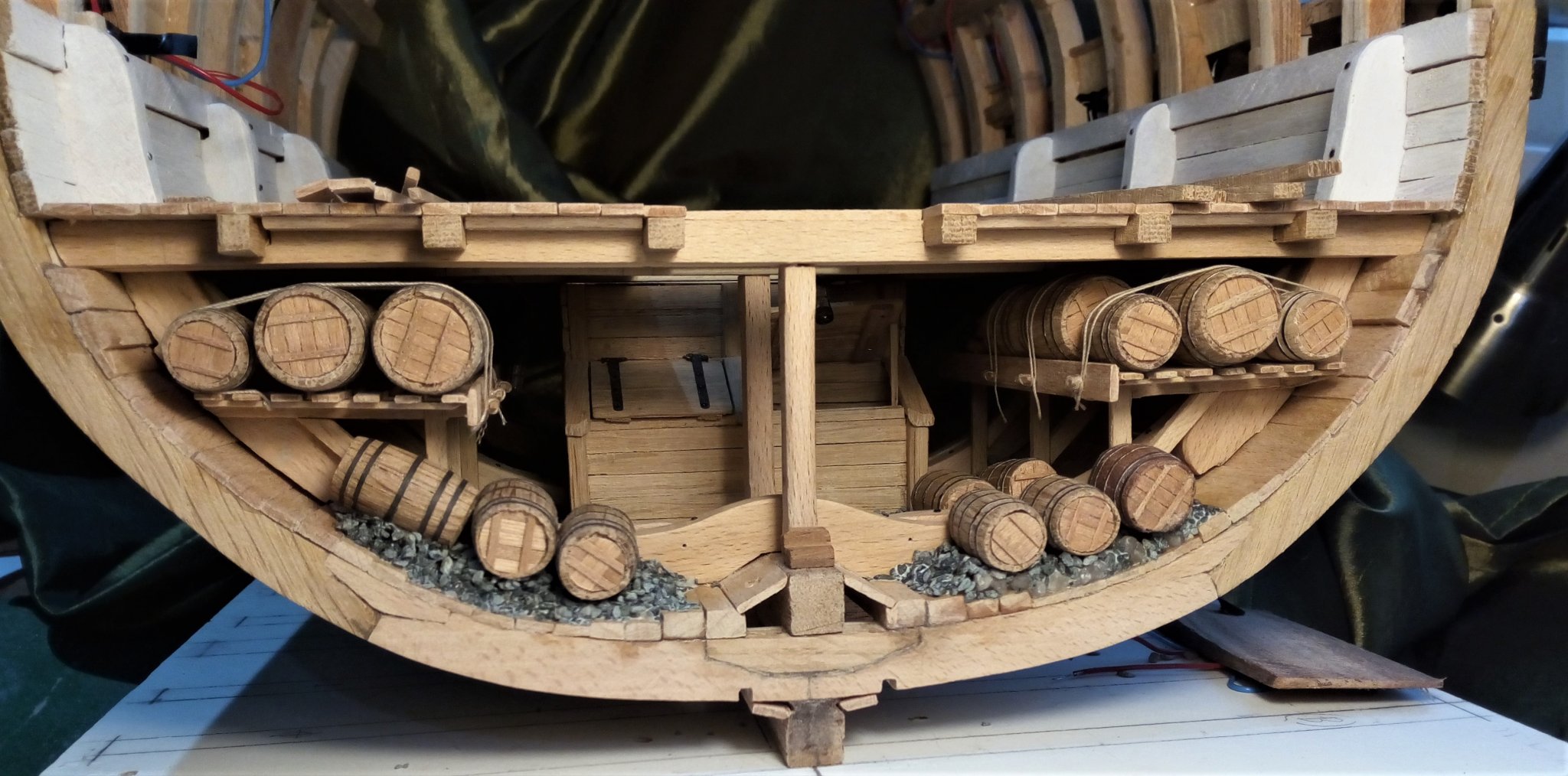
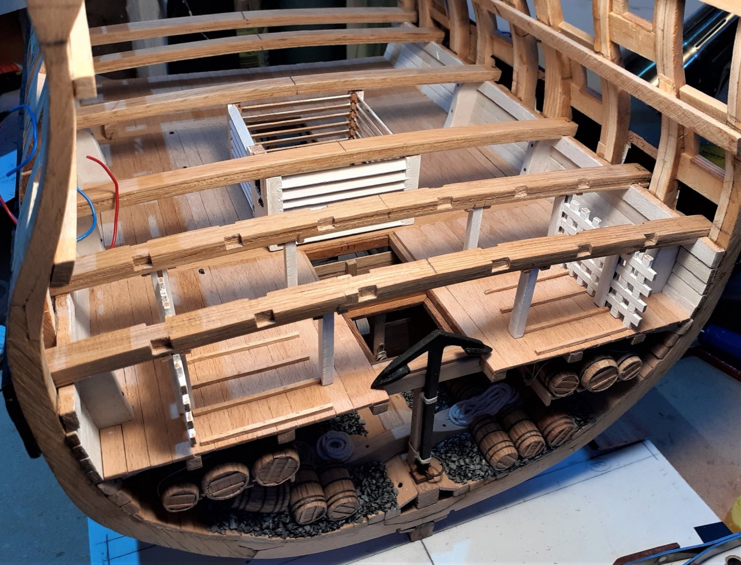
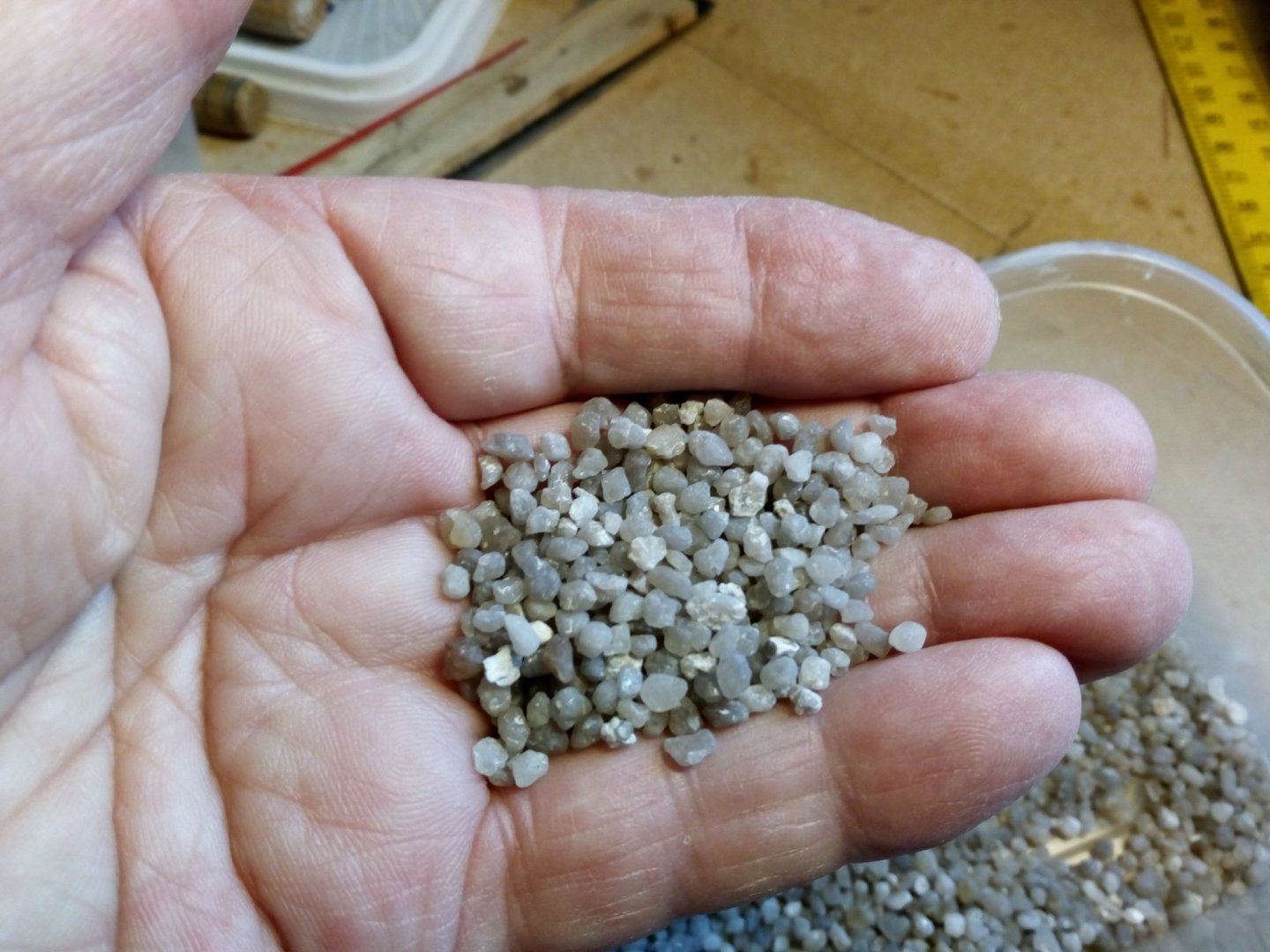
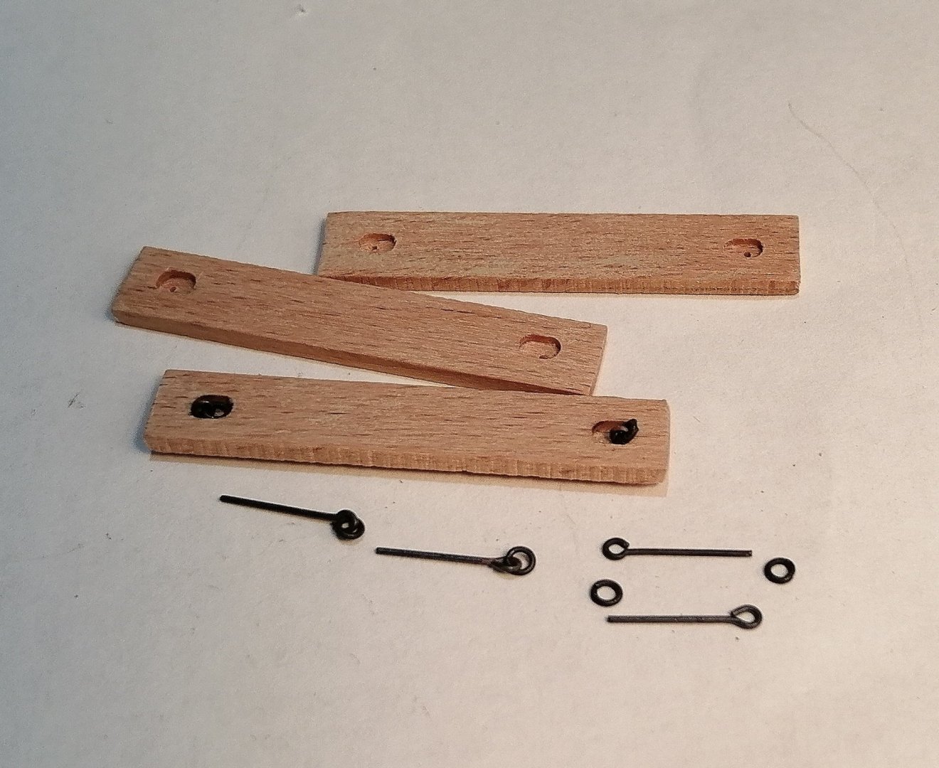
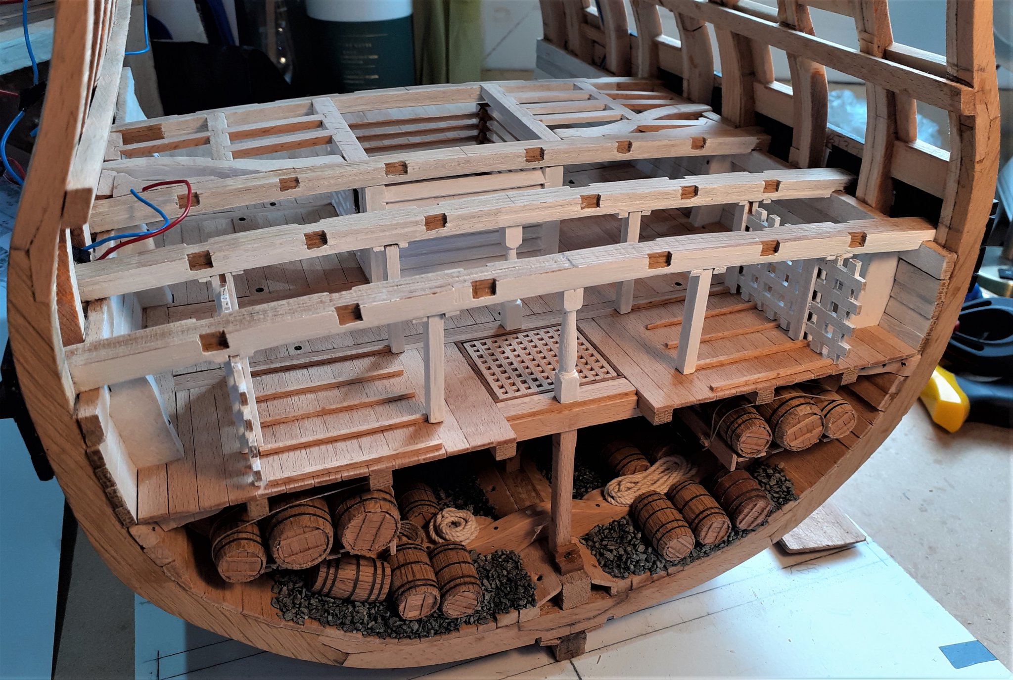
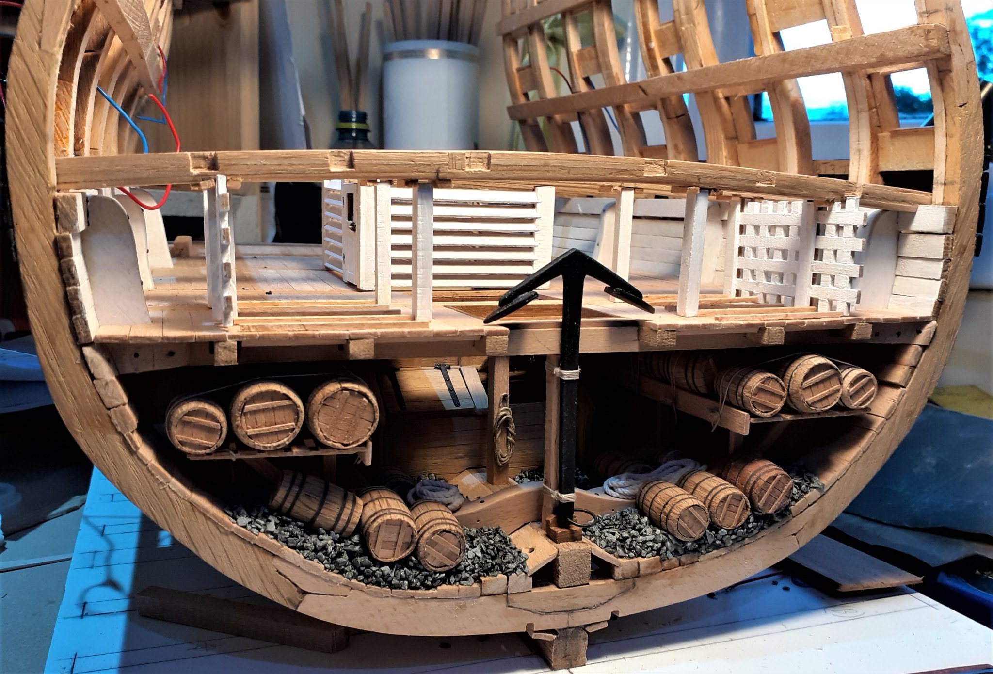
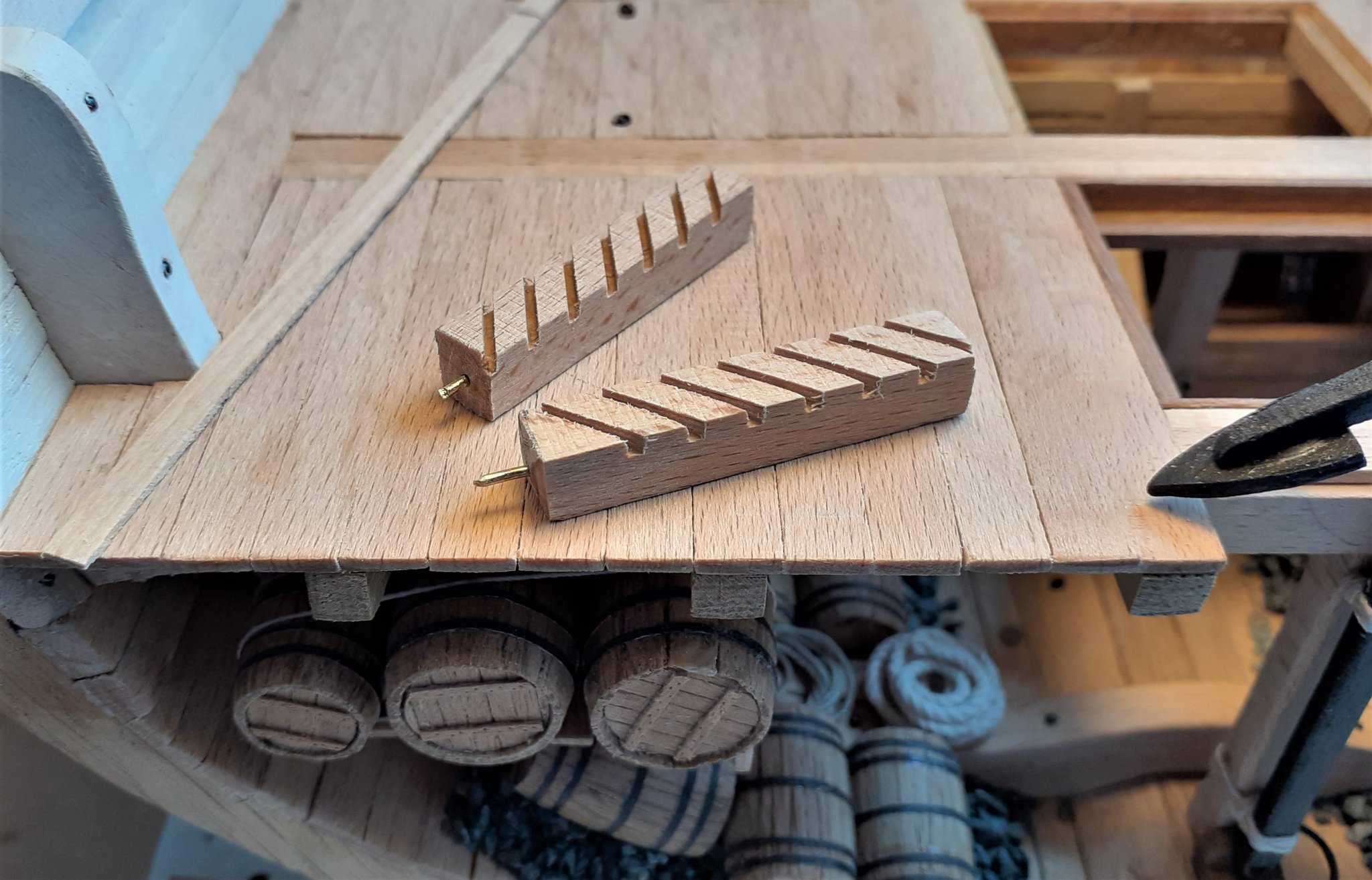
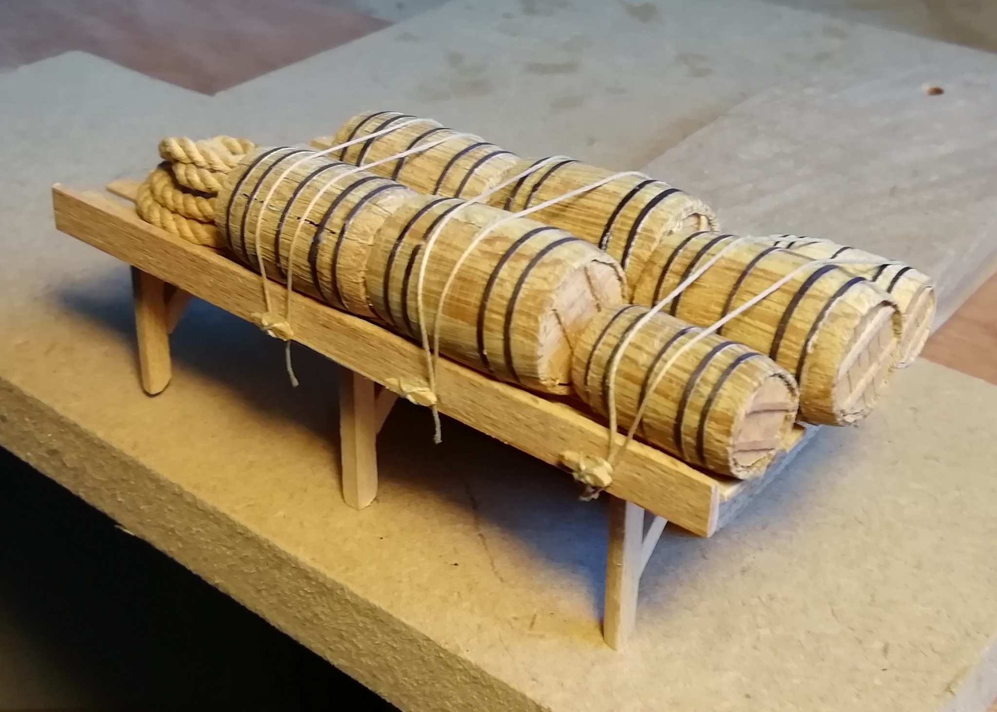
Getting the orlop deck beams and planking done was a forward step -- although it might have been a little easier (and possibly more sensible) if I had finished fitting the barrels and other hold equipment first. It hasn't been impossible but it has been a little awkward getting some of the stuff tucked away under the orlop deck. I've now done 30 barrels, most of which are complete with bands and lids with just a few still to be finished. These pesky little barrels sure take some time! Looking around other build logs has given me some ideas of what to put in the hold in the absence of any information on the 50 gun ships' holds. A couple of racks for holding barrels and other things. This is the one for the port side. I couldn't imagine the barrels just being placed on these racks without being secured somehow, so I included a few cleats and lashed the barrels on. In position > For ballast I bought some aquarium gravel which looked to be about the right scale. But when I saw it with a few barrels sitting in it, it just looked too big for scale. I found that the gravel I had left over from a model railway project looked much better, so railway ballast it is > Both sides > When I have finished squeezing more barrels under the orlop, this anchor will eventually be lashed to the pillar. Orlop deck being used as a timber storage area right now.


.thumb.jpg.3c7a5035a9c6ae1807fece766f99a9cb.jpg)
.thumb.jpg.7829ff5aeb4099420f41b8c0121cbf50.jpg)


- 66 replies
-
- 11
-
-
Hello Johann, If any build you have done isn't 100% accurate (according to the available information) then I don't think many on this forum, or anywhere else would know! If I ever win several hundred million €uros in the €uro lottery I will employ you to oversee the building of my dream sailing ship -- that way I would know it was built to the highest standard!
-
Johann, When the original La Creole was built in 1827 did they actually include all these details !!! Just WOW !
-
Tom, it's great to see someone so happy to be doing ratlines! . . . and you're not going to count them ??? (Welcome to the mushy brain club!)
-
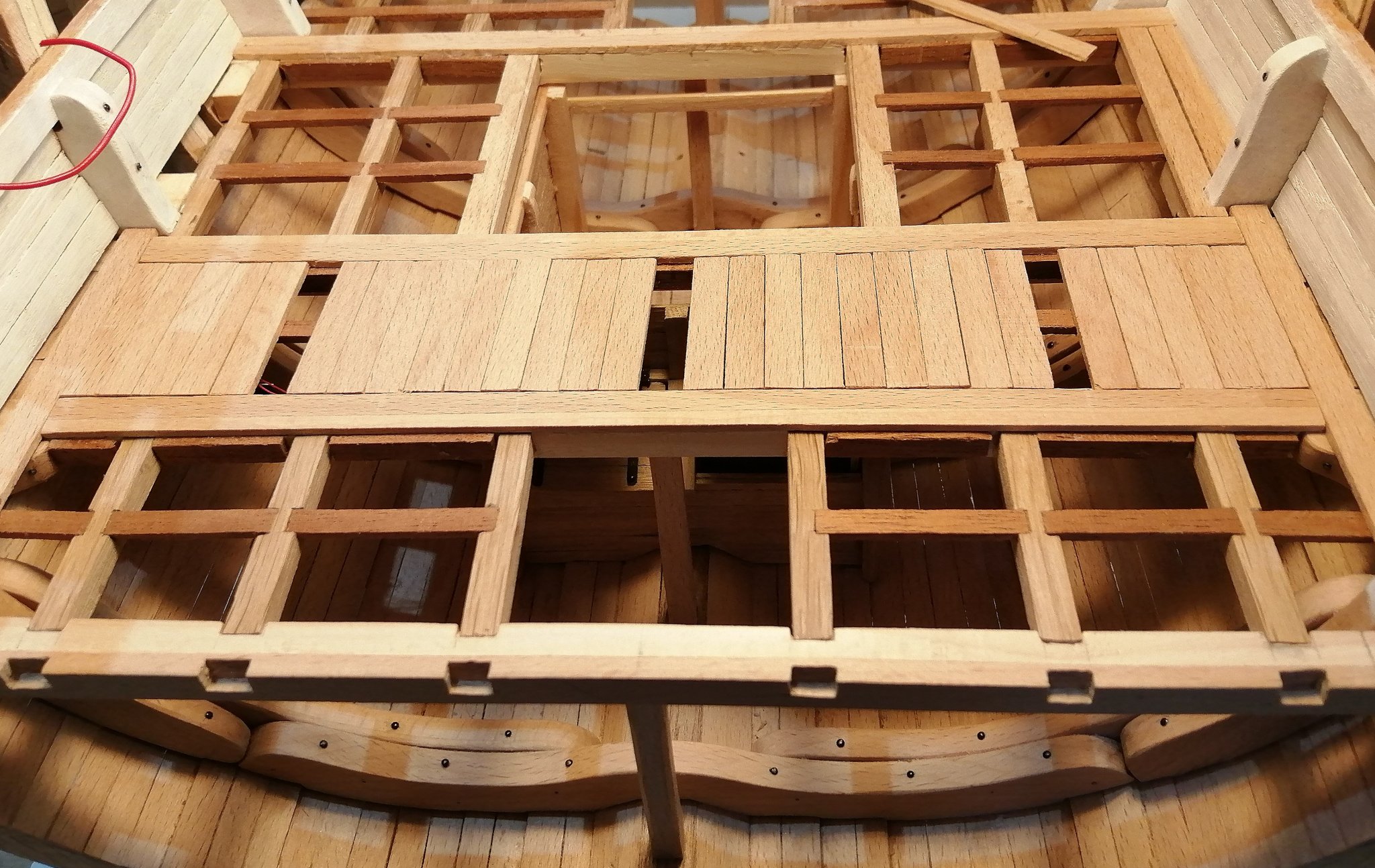
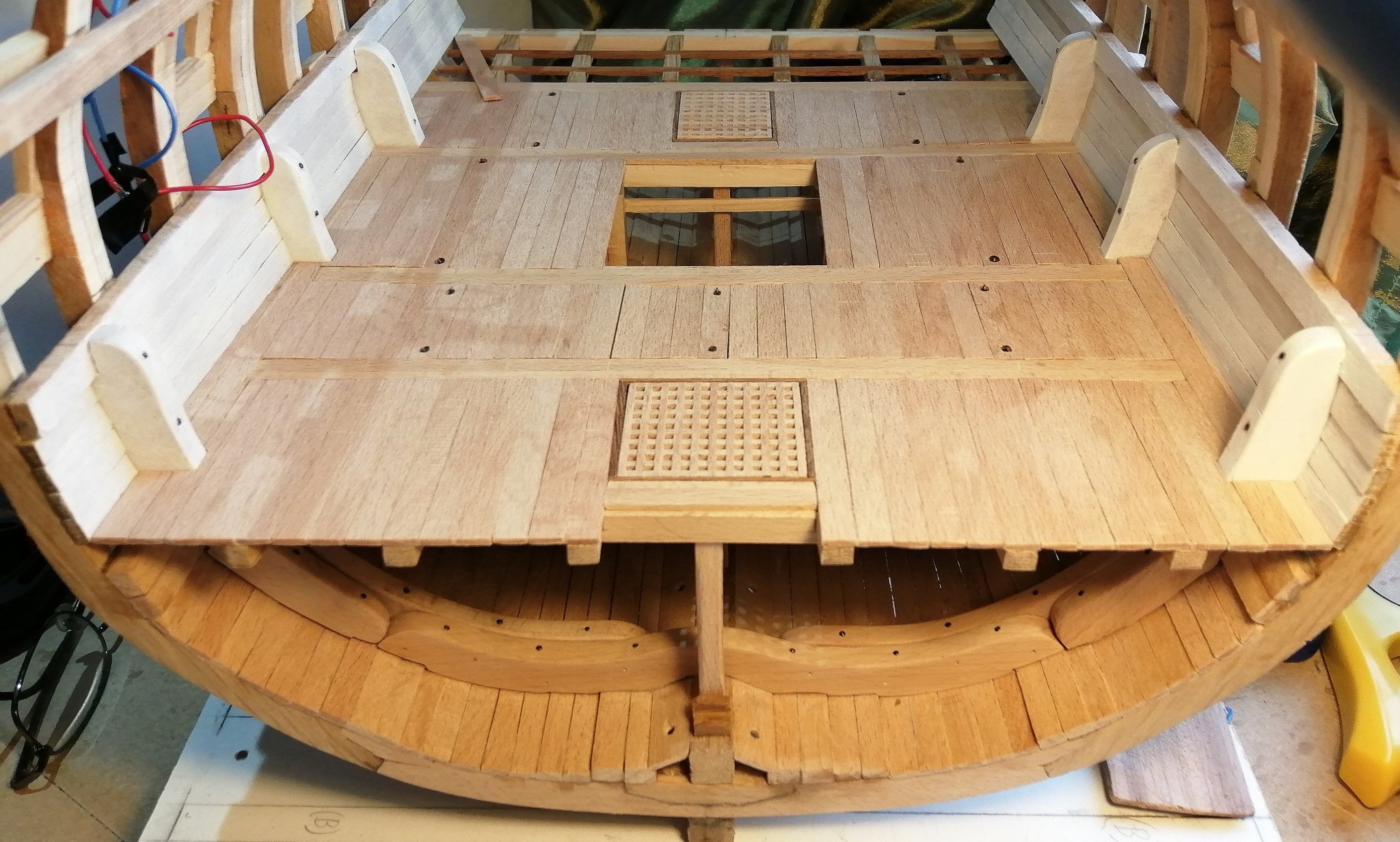
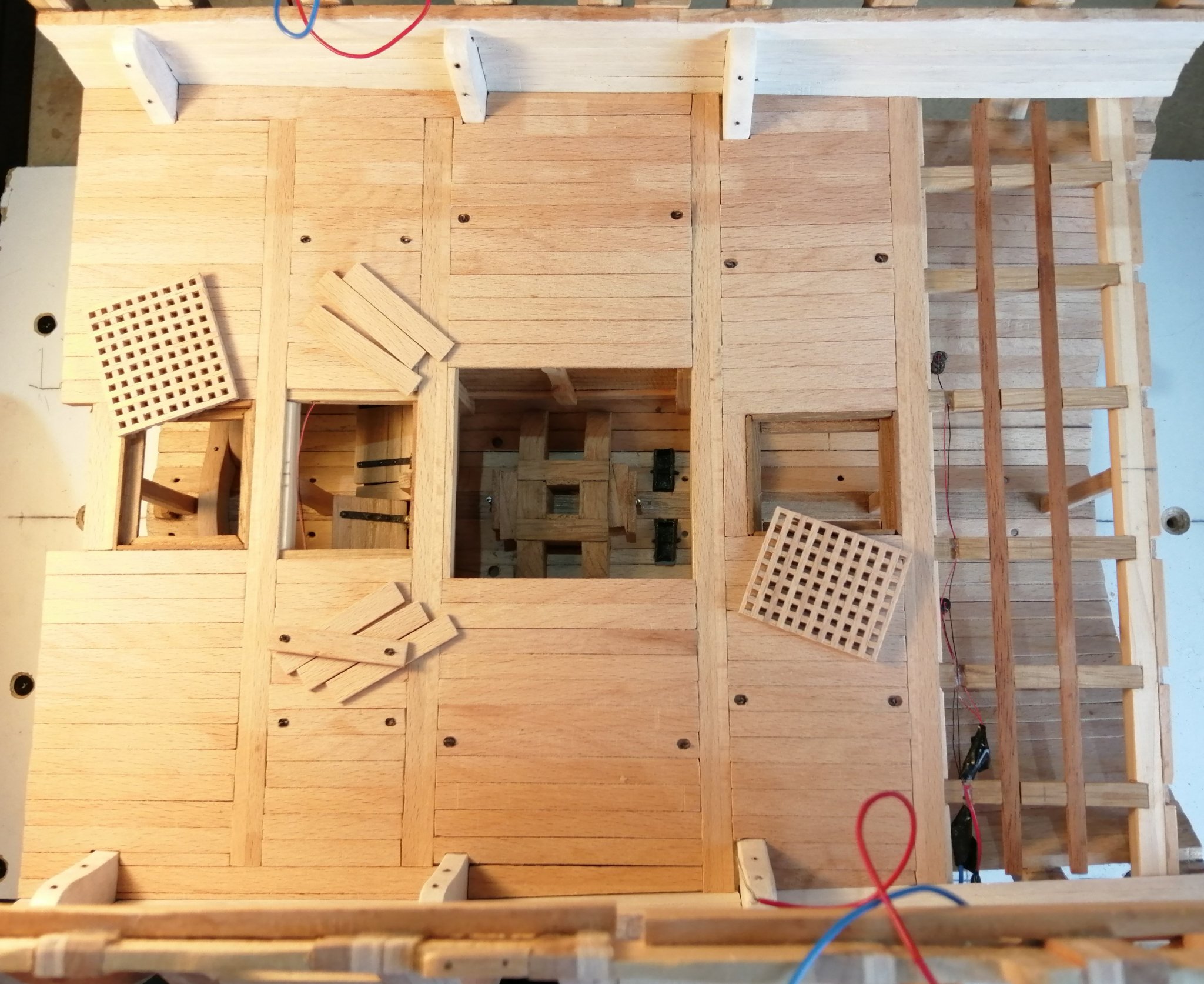
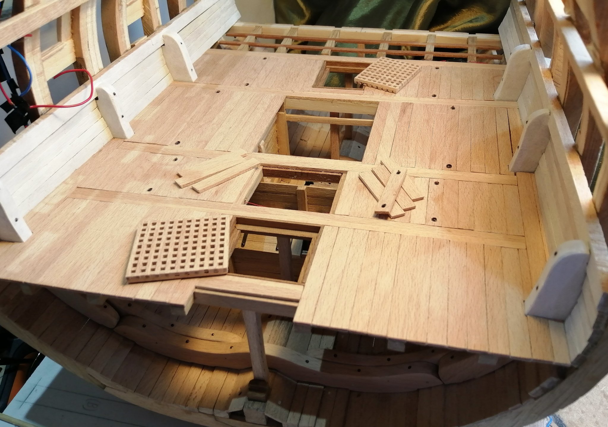
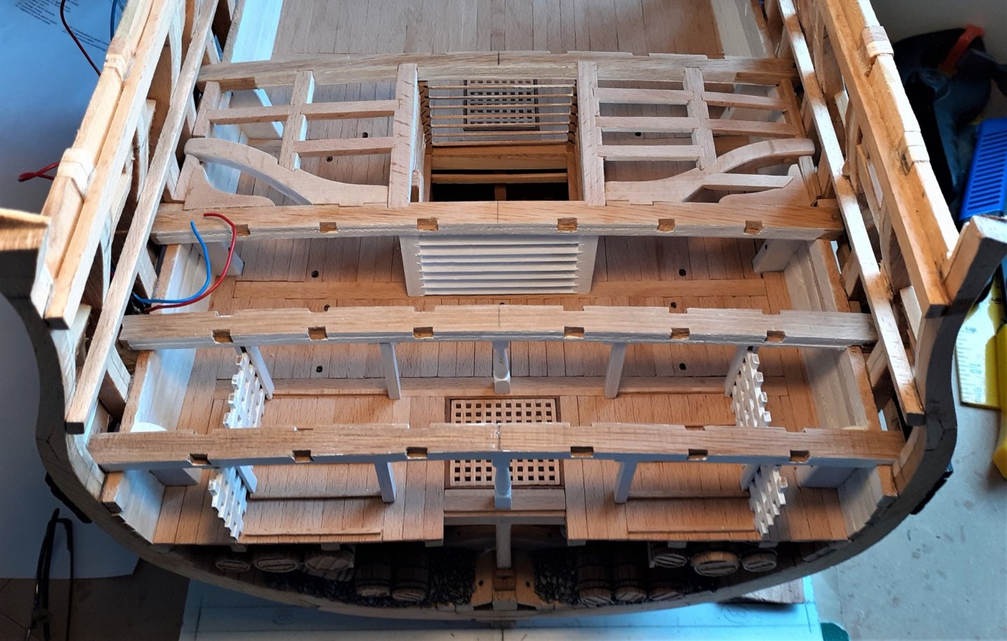
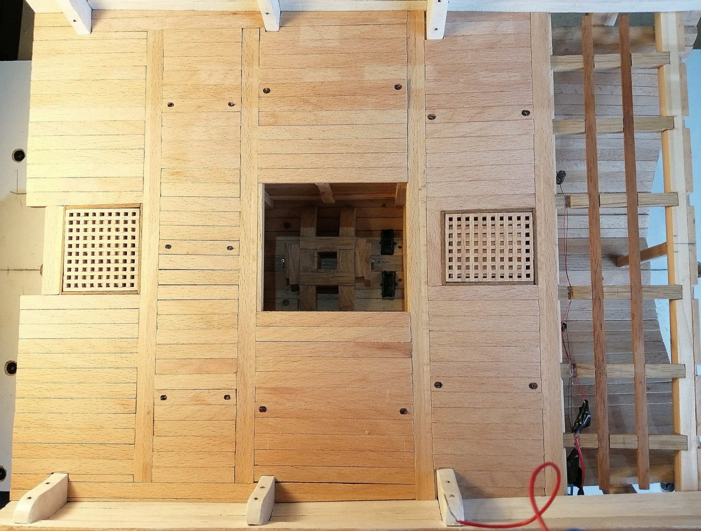
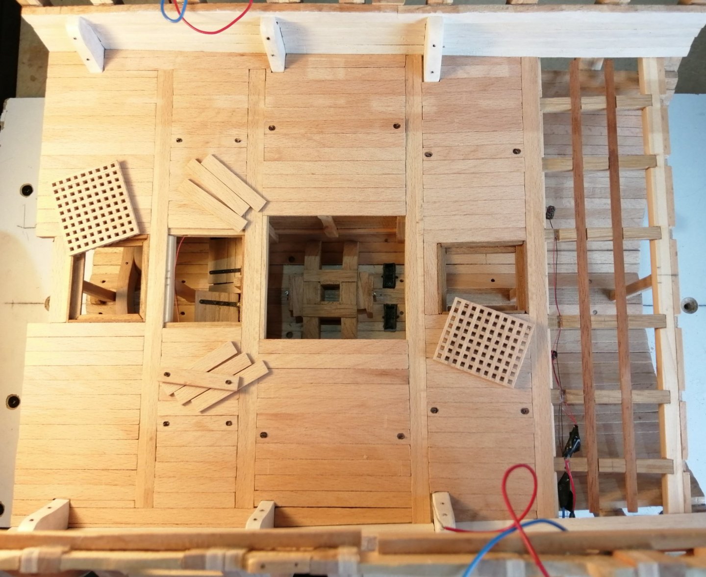
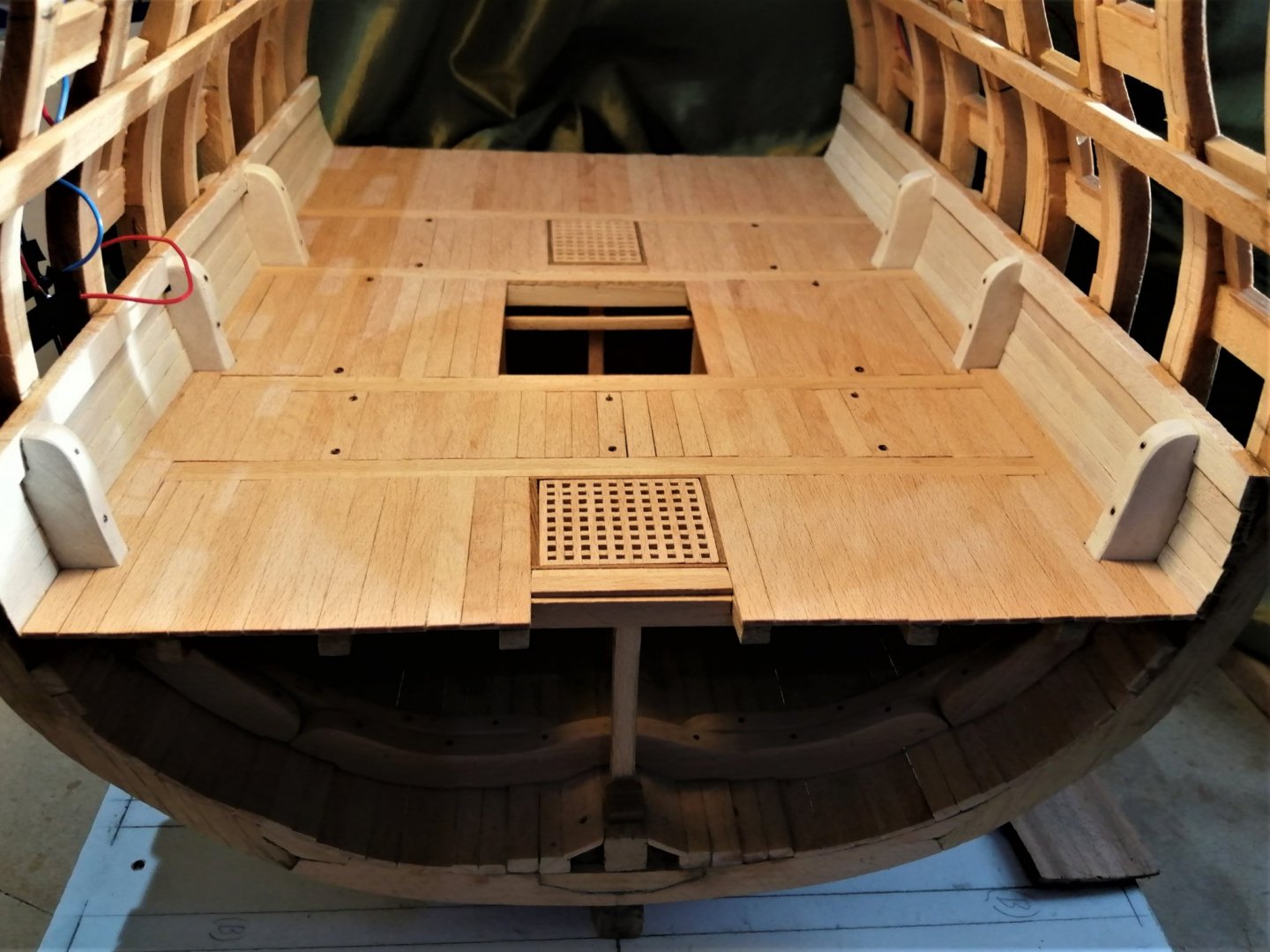
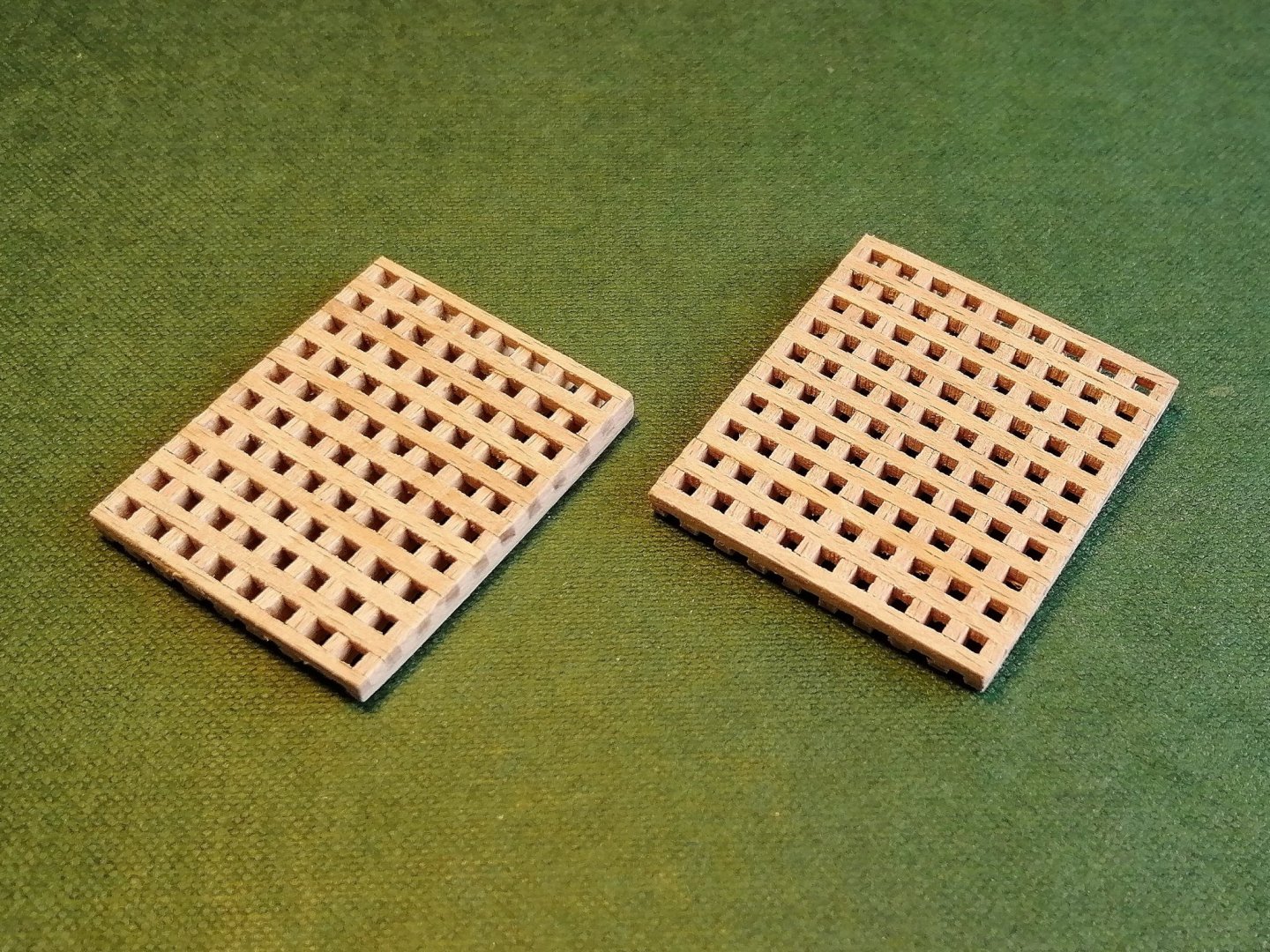
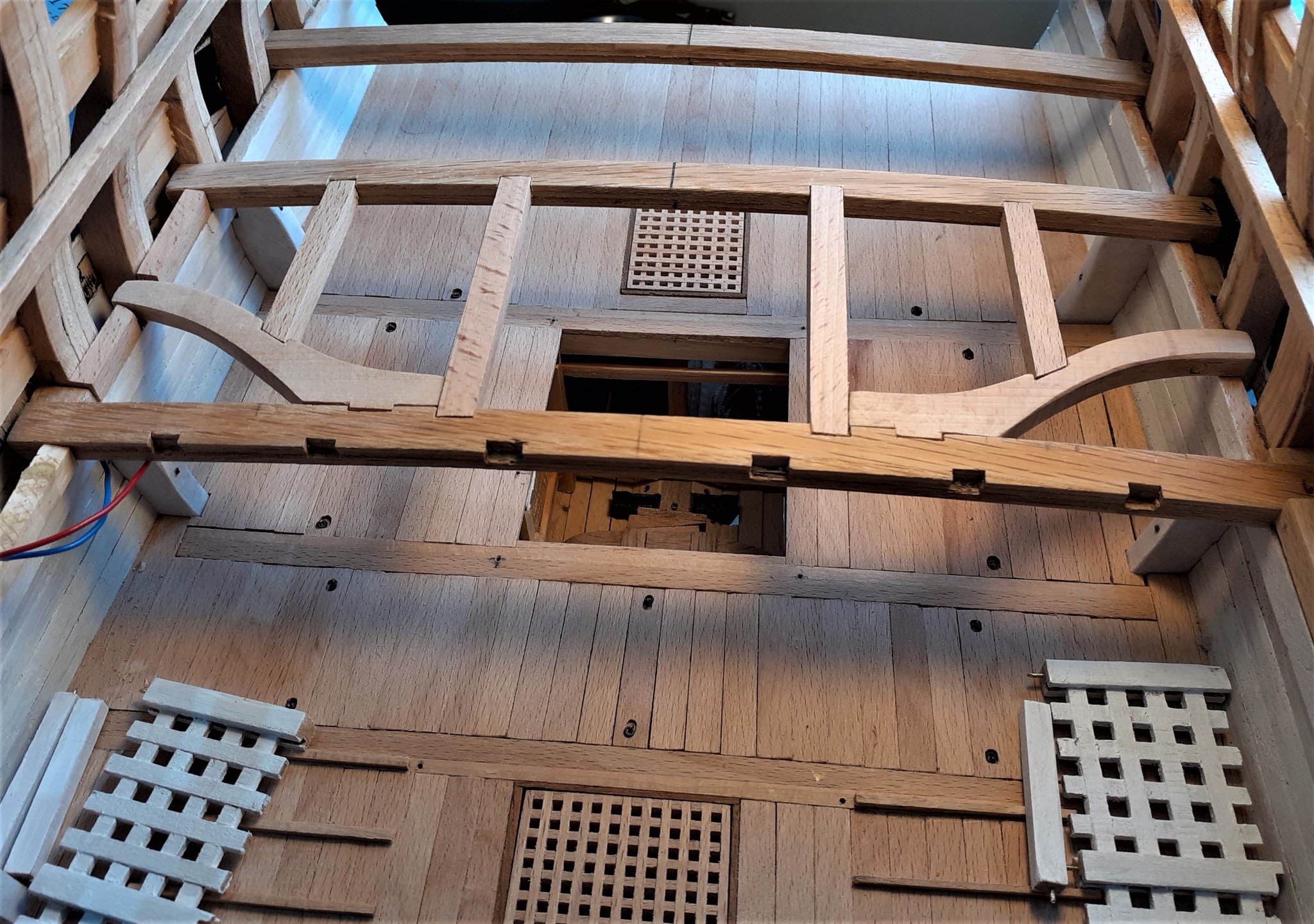
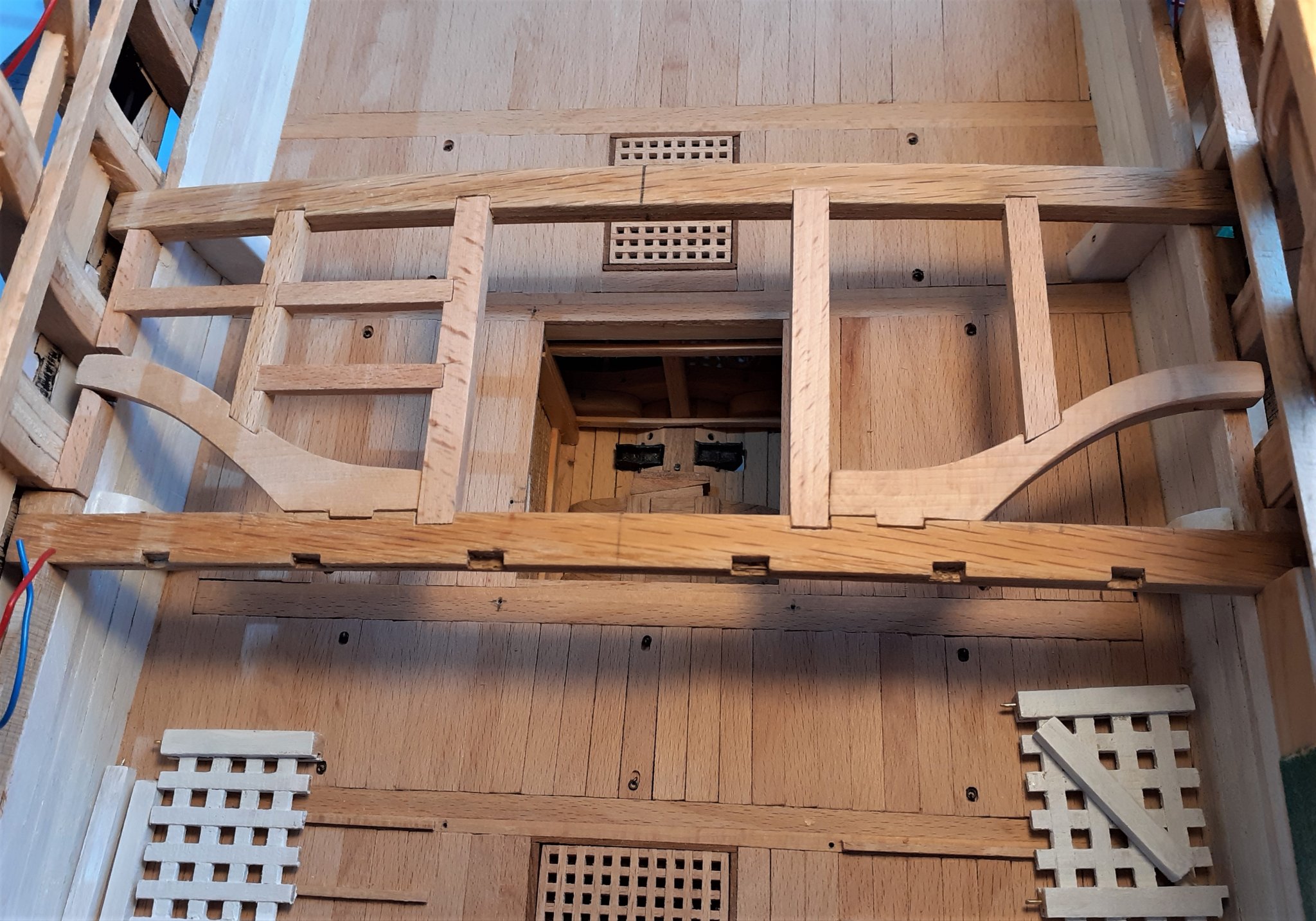
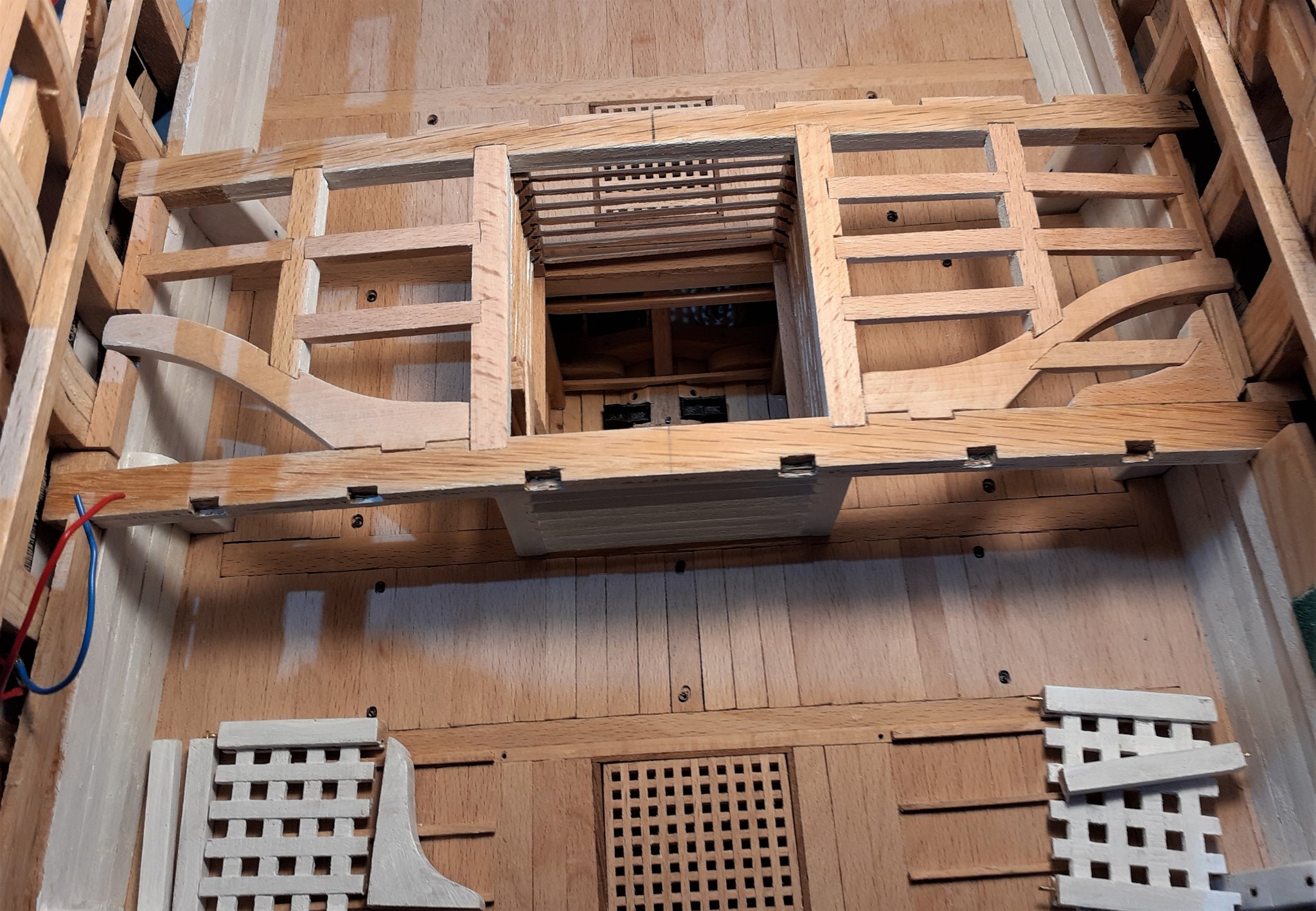
Thanks for the comments, G.L. and Guy and to the others for the likes and visits. Some progress on the orlop deck. The only drawing I have showing the configuration of the orlop deck planking is this > Every time I had looked at that drawing I didn't understand why these planks were different to those on the gun decks and quarterdeck -- until recently when trawling through some build logs on here. Then it made sense to me --- a number of the orlop planks are removeable in order to create more access to the hold. As they're arranged in sections across the ship this was my first attempt > The 3 empty spaces are for these > I don't believe that all of the removeable planks had lifting rings and only a few would need these rings. The 'plain' planks could have been lifted once a 'ringed' plank had been lifted. A week or so and about 80% had been done. With the gratings and a few planks lifted out. Then the deck was finished. The gap immediately ahead of the fore grating will later accommodate this > Some of the above photos reveal that the orlop inner hull planking is done and is painted white. (I believe it was called 'white stuff' in sailing days.) It seems it was the practice to paint the 'walls' and 'ceilings' of all decks from the orlop upwards with 'white stuff'. It served to create better visibility down in these rather dark decks and it will help brighten up the inside of this section.


- 66 replies
-
- 10
-
-
Hi Tom, I don't know exactly how you created the keel (for the frames) and the fore and aft 'spine' onto which you attached the bulkheads but I'm guessing you may have made something like what I've tried to draw below? (I assume that from stem to stern the "thing" had to be a single piece, or a manufactured single piece?) Maybe that's what Guy is trying to see?
-
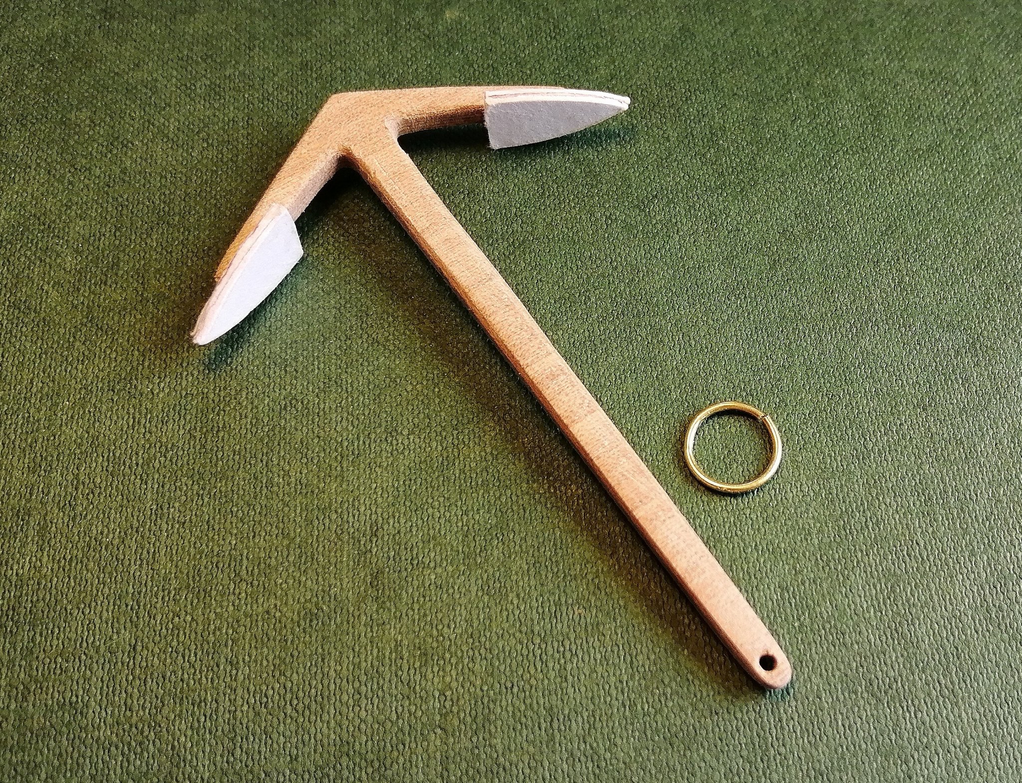
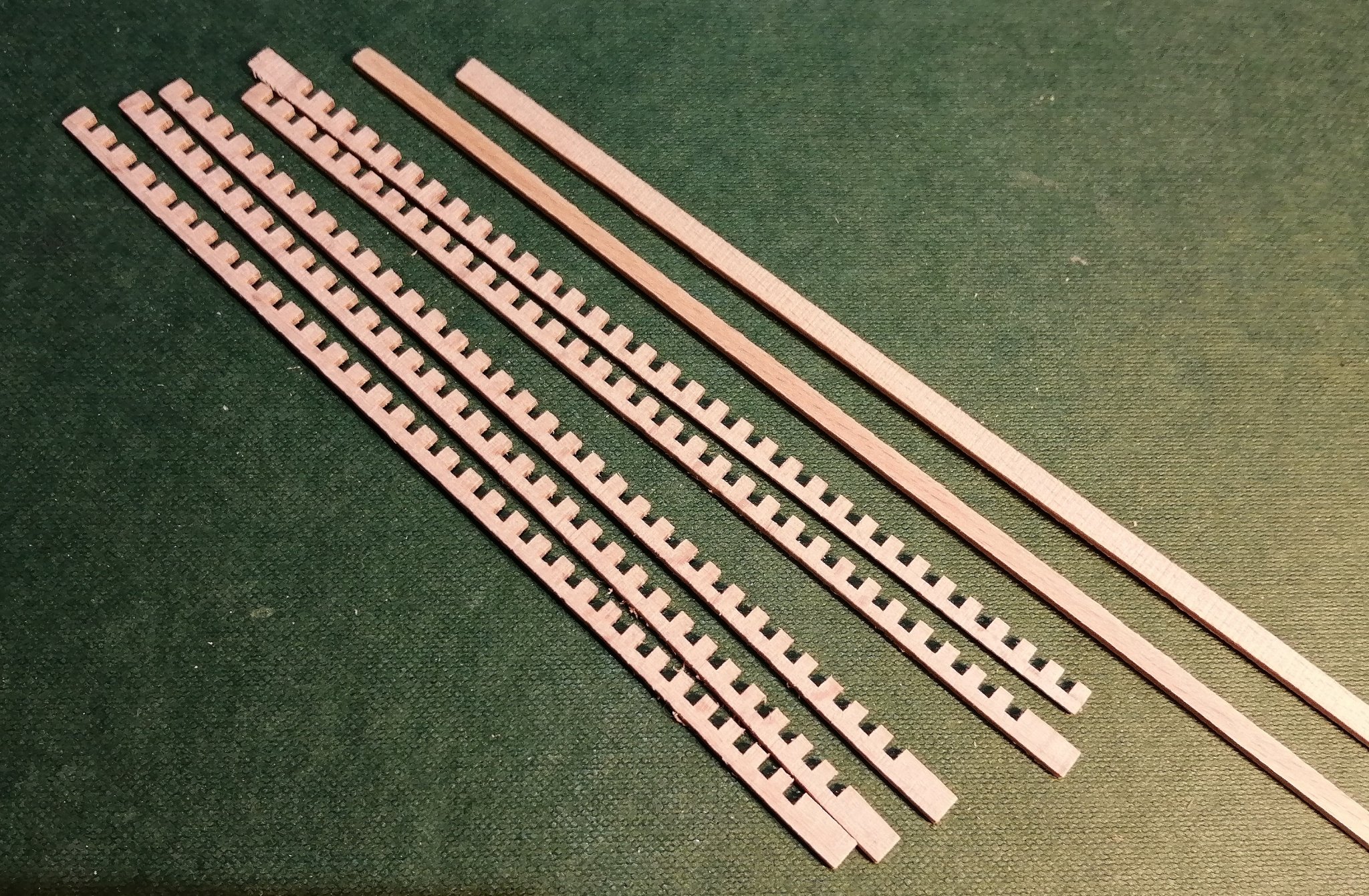
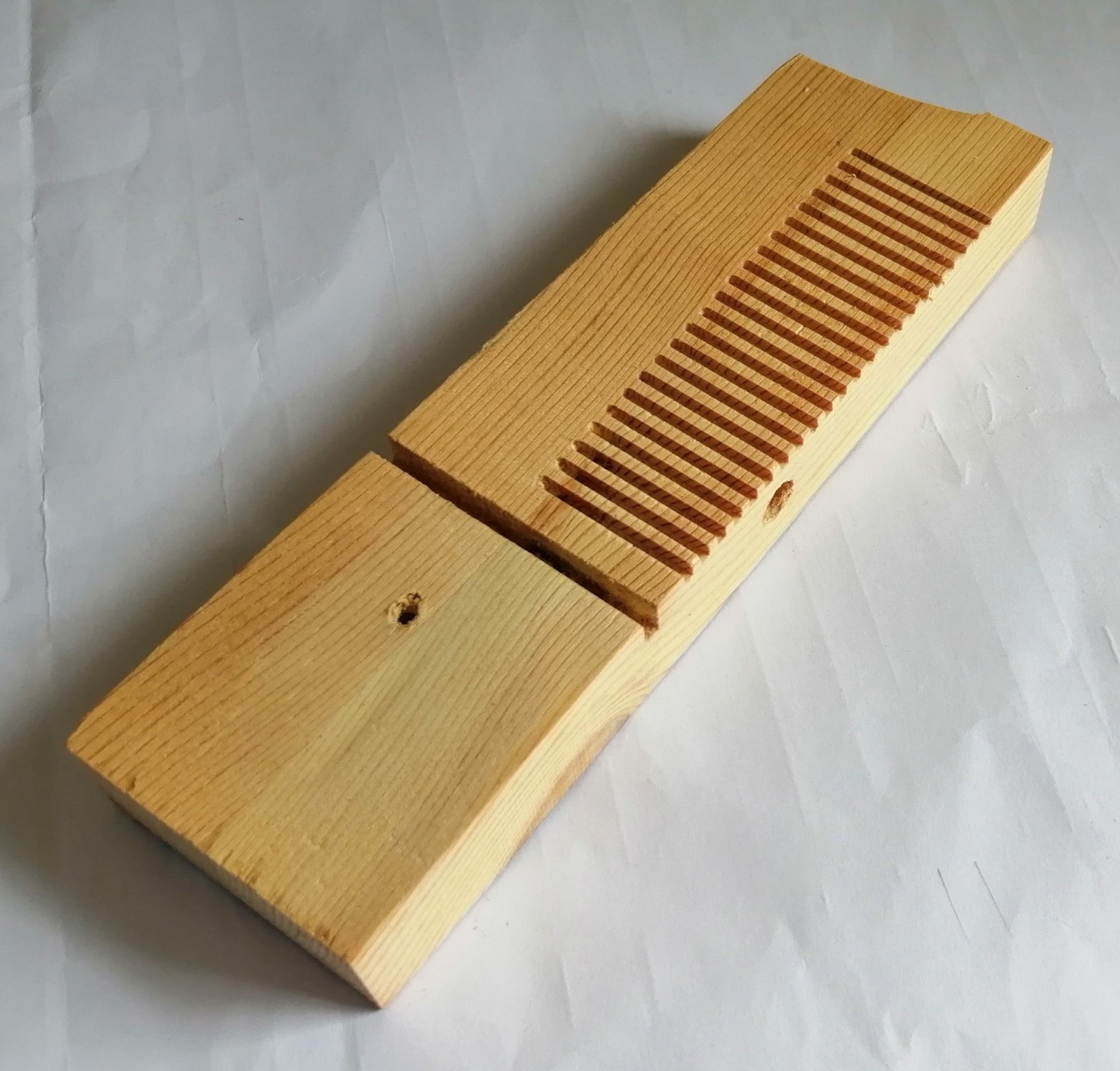
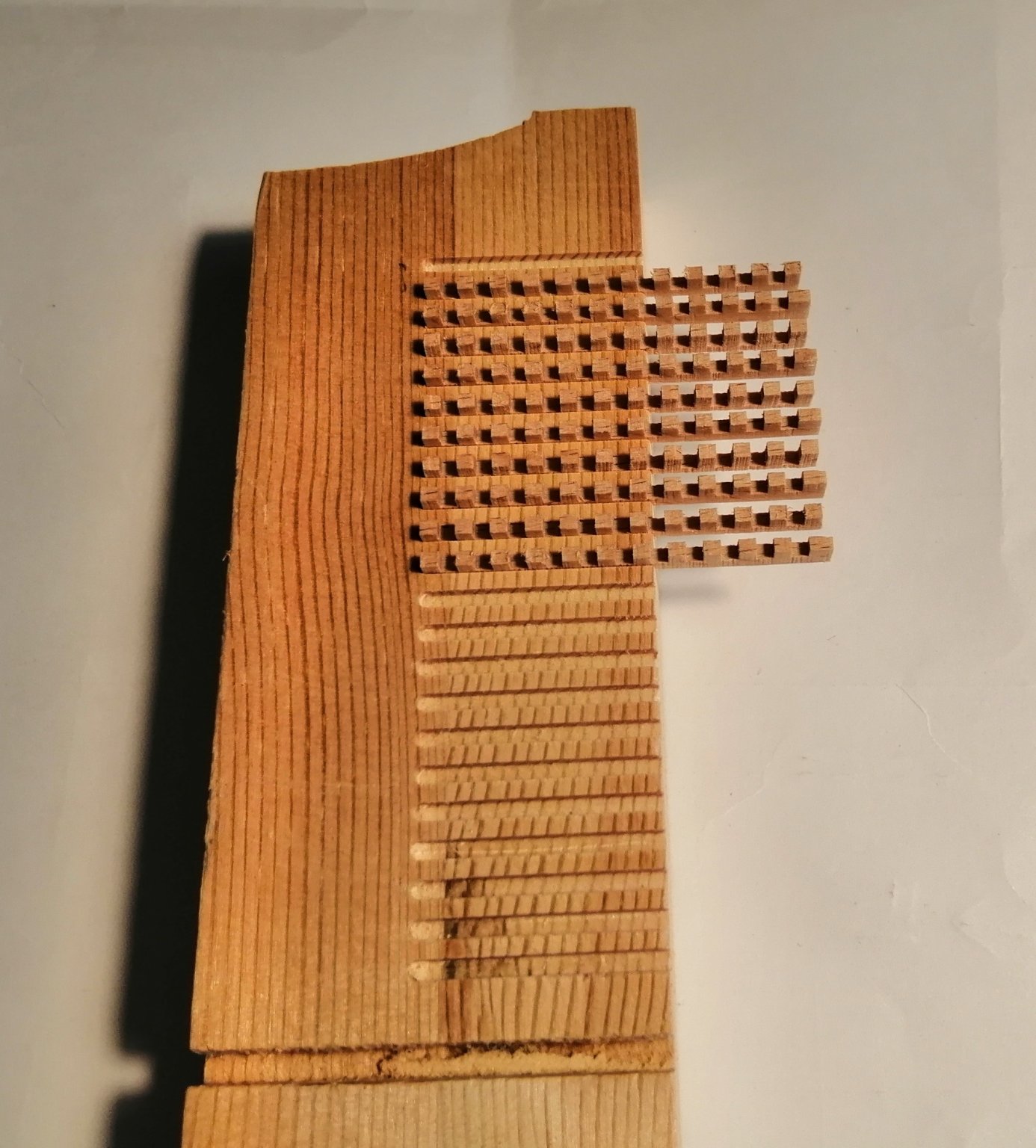
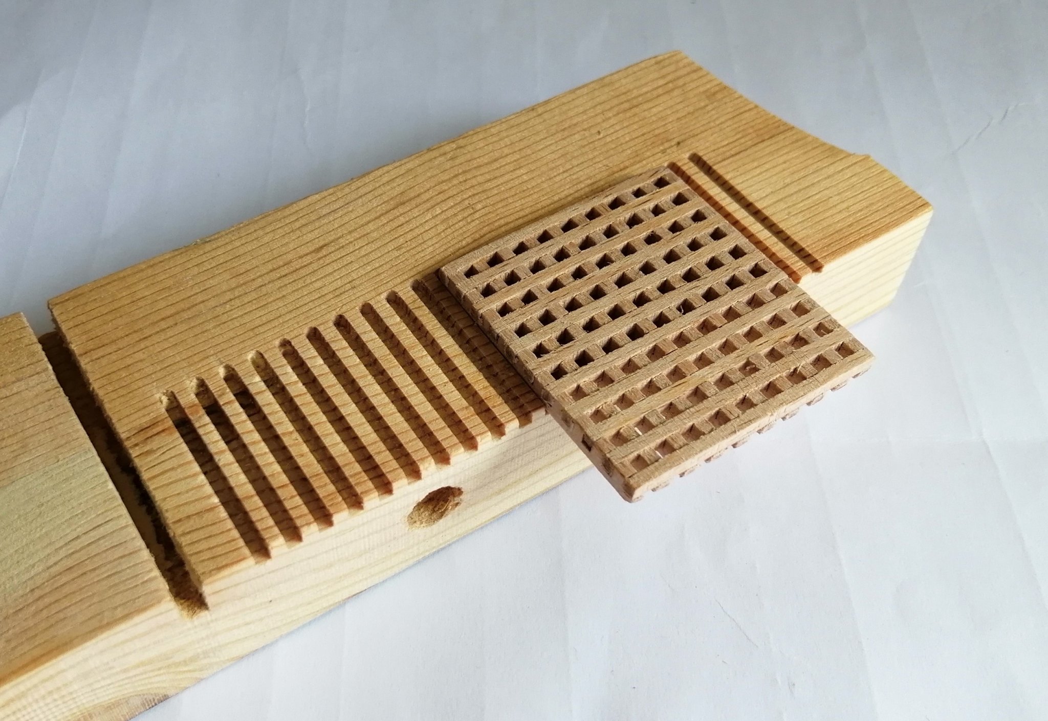
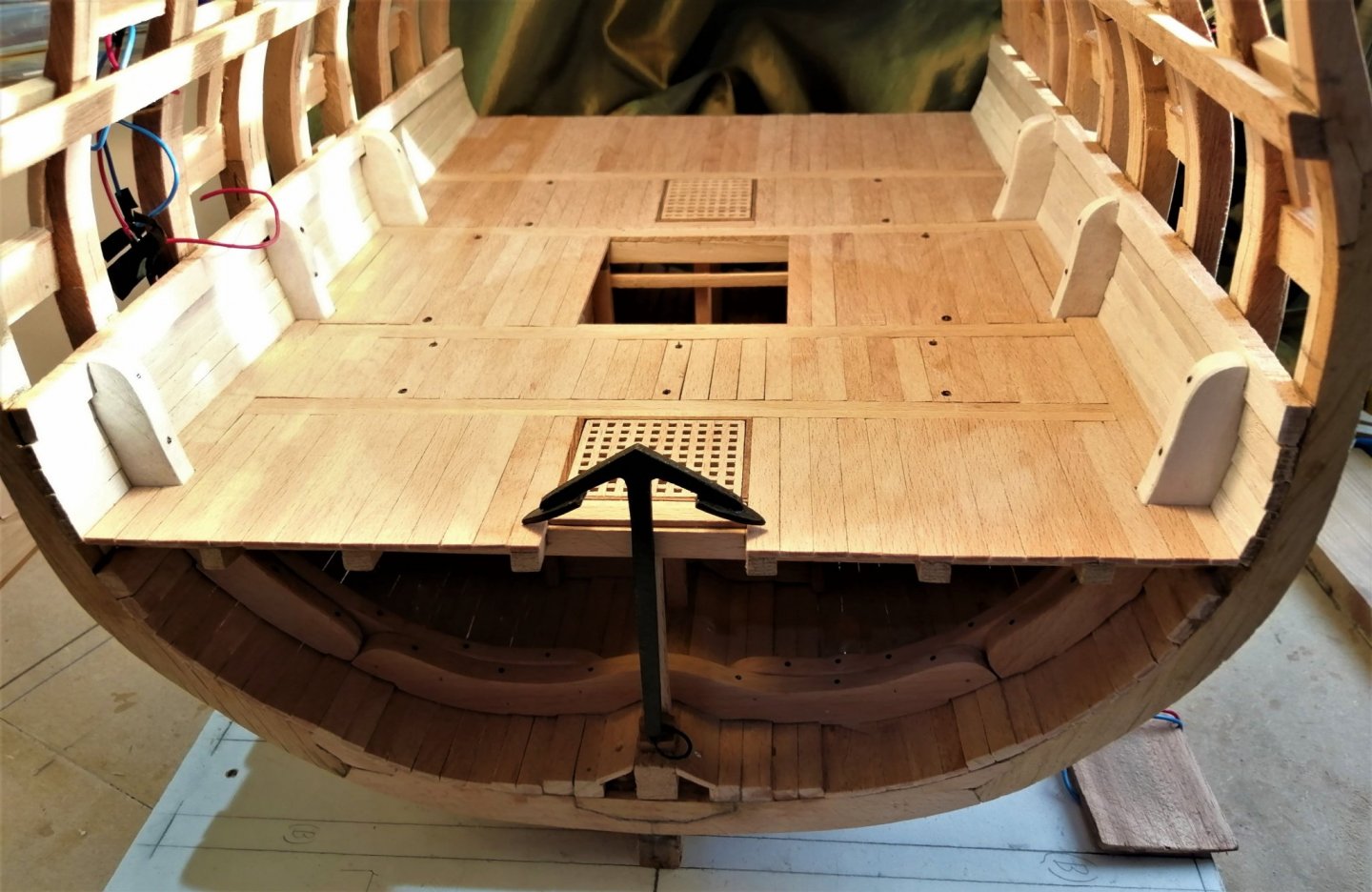
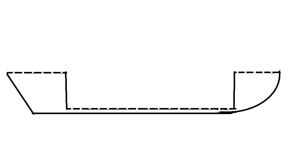
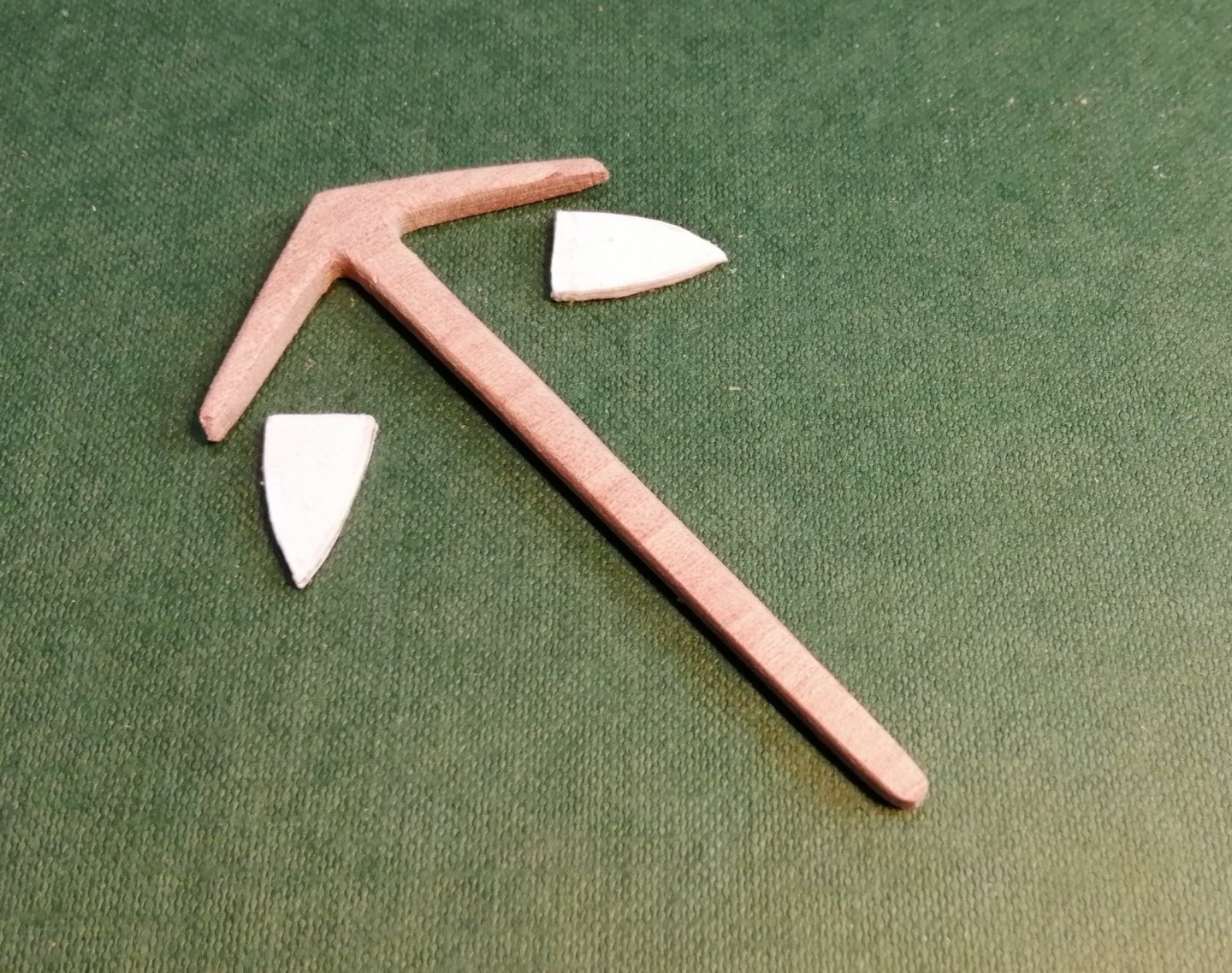
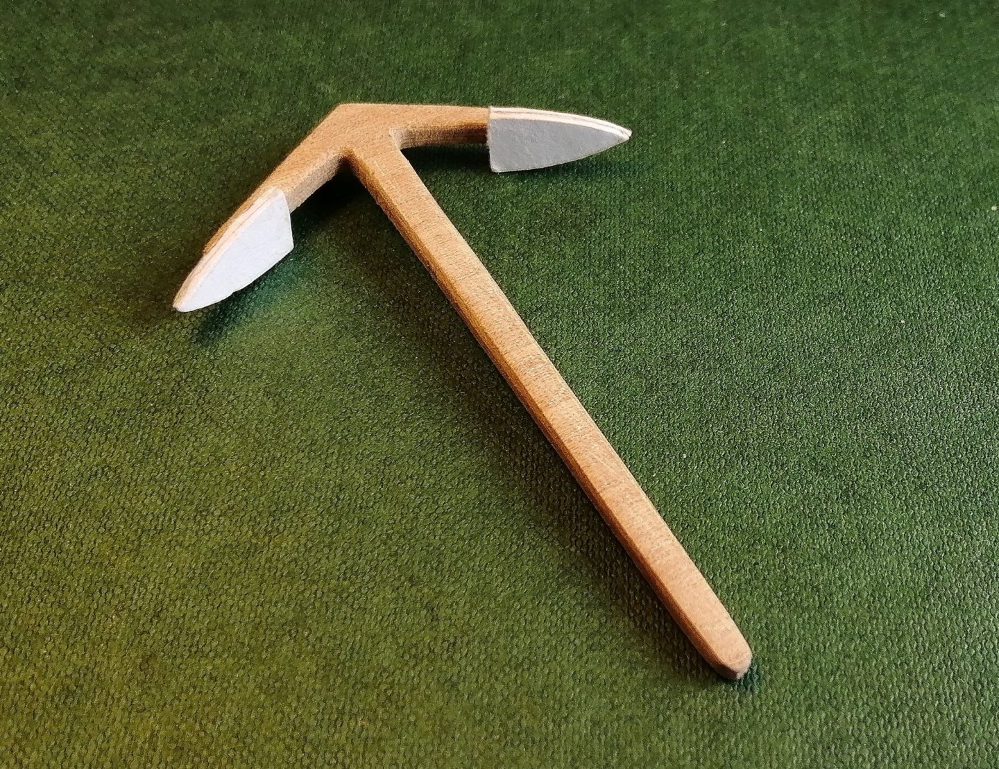
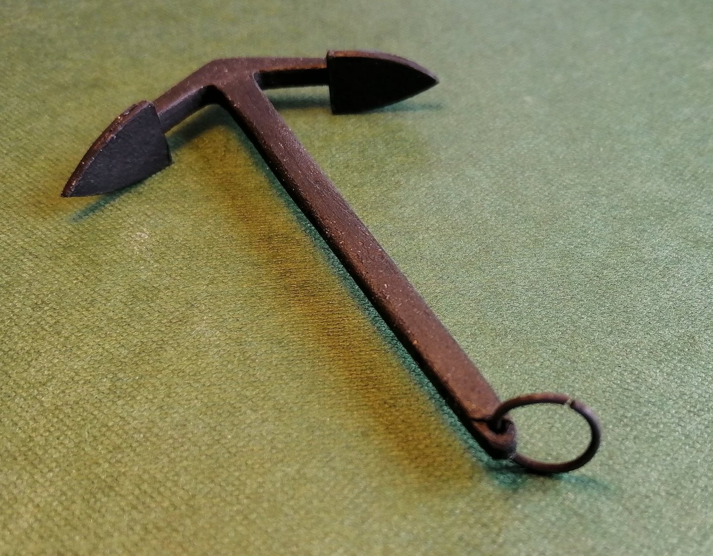
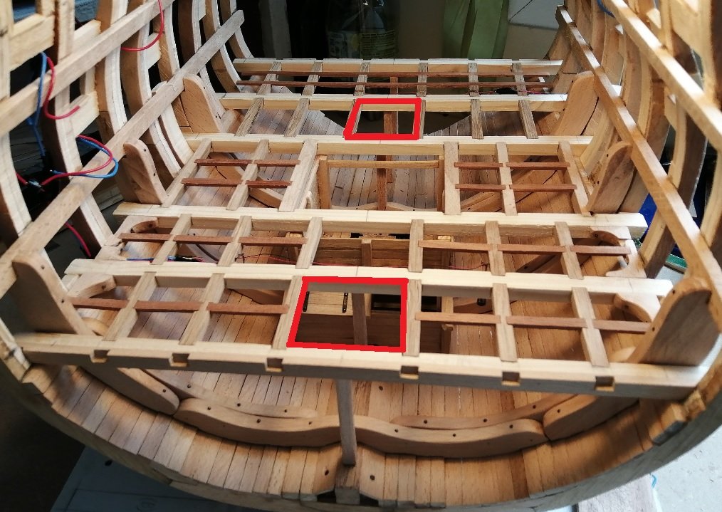
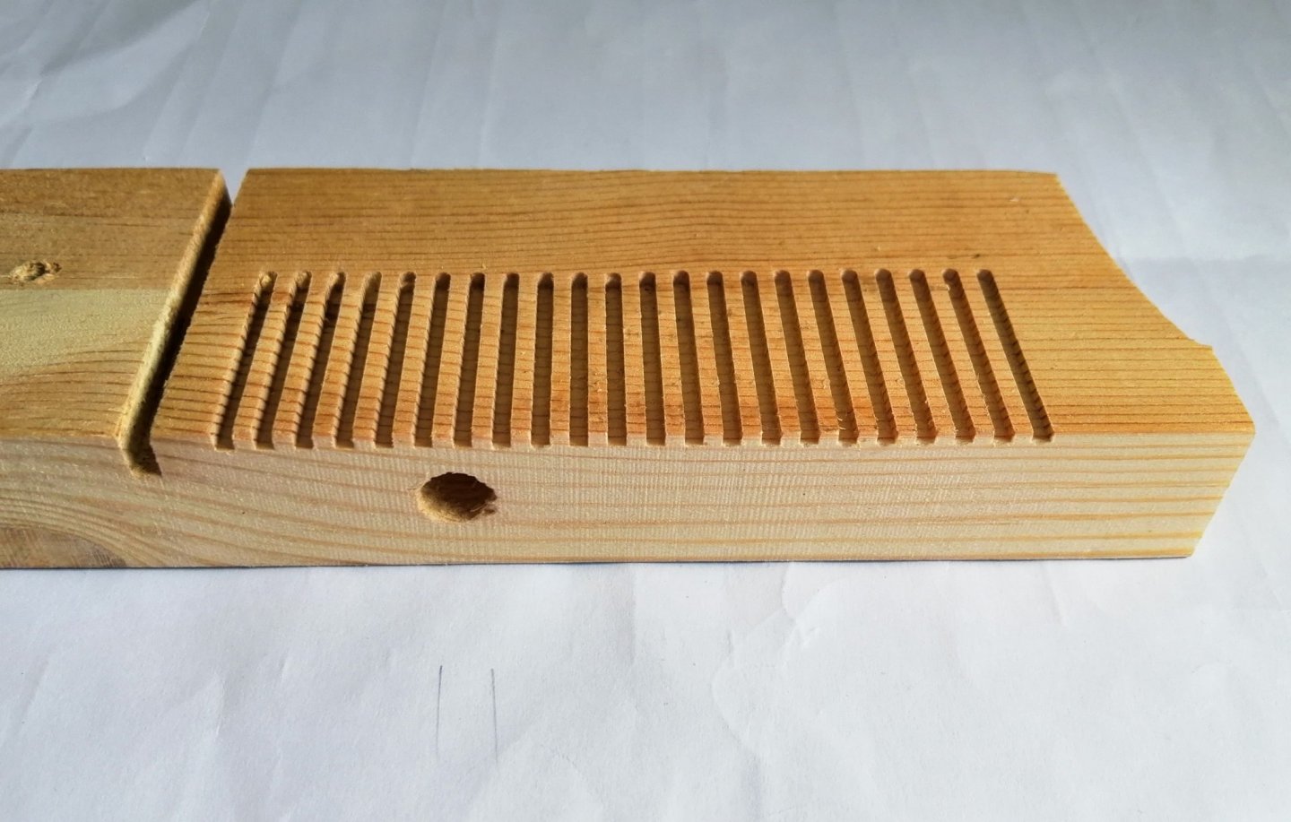
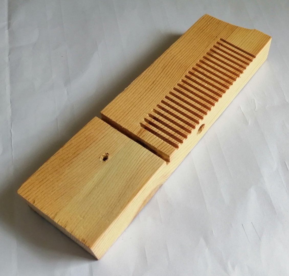
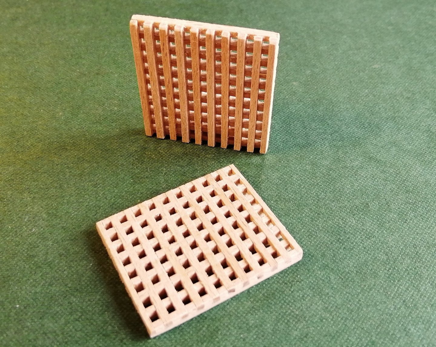
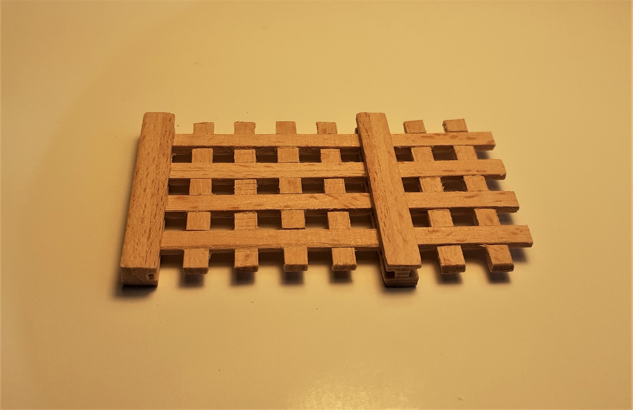
Looking around for ideas for things to put in the hold I spotted one build with an anchor lashed to one of the pillars. First attempt at making an anchor as for my other build I had just bought and assembled the anchors. Didn't have any suitable brass so, wood it would be. A lamination of about 7 layers of 0.6mm veneer gave me a 'chunk' of wood from which to cut a blank for an anchor. The blank, with flukes just made from 3 layers of card glued together and cut to shape. With the flukes glued on. Only metal part is the ring made from 1mm brass wire. and some black acrylic paint made it look a little more like an anchor. In post #17 above I mentioned a future grating. Along with the removable planking on the orlop deck I plan to include 2 gratings which will occupy the spaces outlined in red in the following > That milling machine was in use again cutting the 'grooves' in the 'teeth' of the 2mm strips. A 2mm cutter was used along with strips of 2mm and the 'holes' are also 2mm, which, at this scale equates to just over 3 inches (C.80mm) which I believe was close to the Navy Board's 'establishment'. While the 'teeth' will maintain a regular spacing, that would only be in one direction, so I had to create a jig to keep the spacing correct in the other direction. Another call for the milling machine with its 2mm cutter. This is just a scrap piece of wood and the large hole and groove were already there.


- 66 replies
-
- 10
-
-
Hi Michael, Thank you for your comment. I'm sure you'll recognise the lanterns! At first I didn't have a firm idea of how I would make the lanterns ~~ until I saw the ones you had made for your Santisima Trinidad, then I knew that was the way I would go.
-
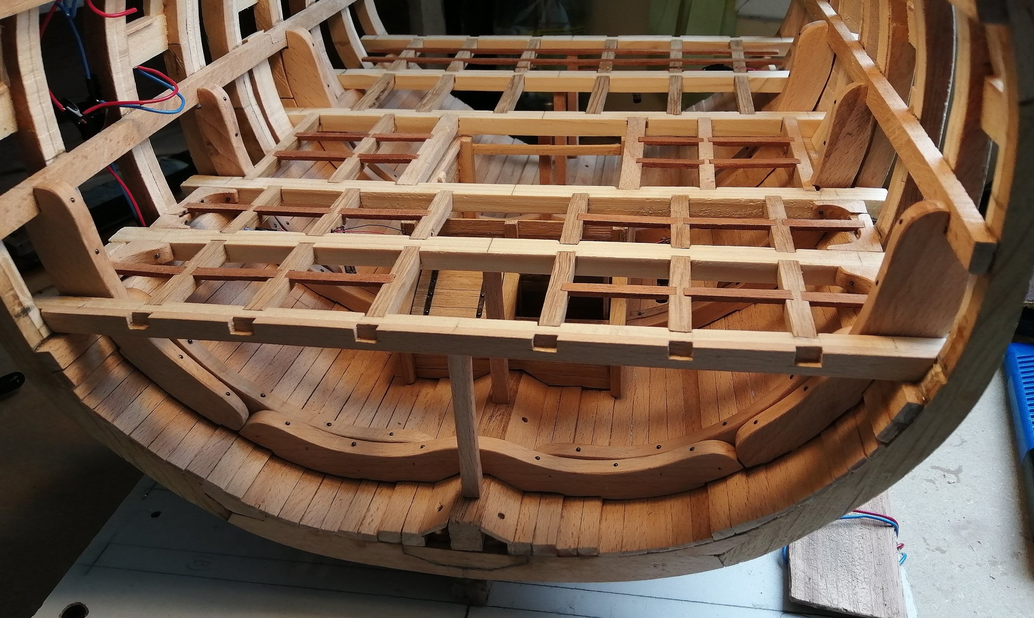
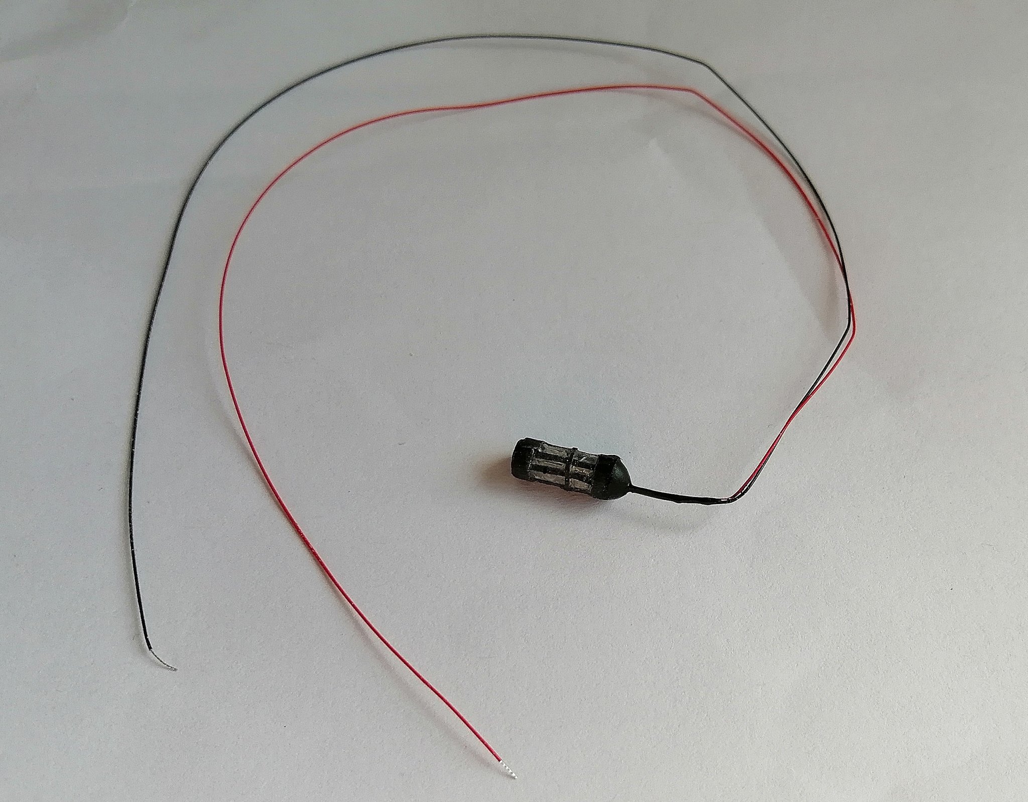
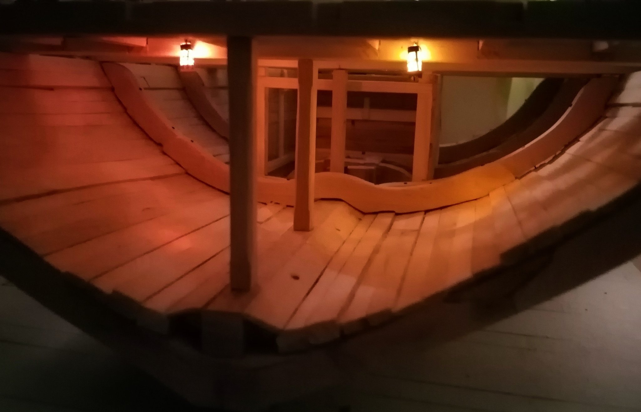
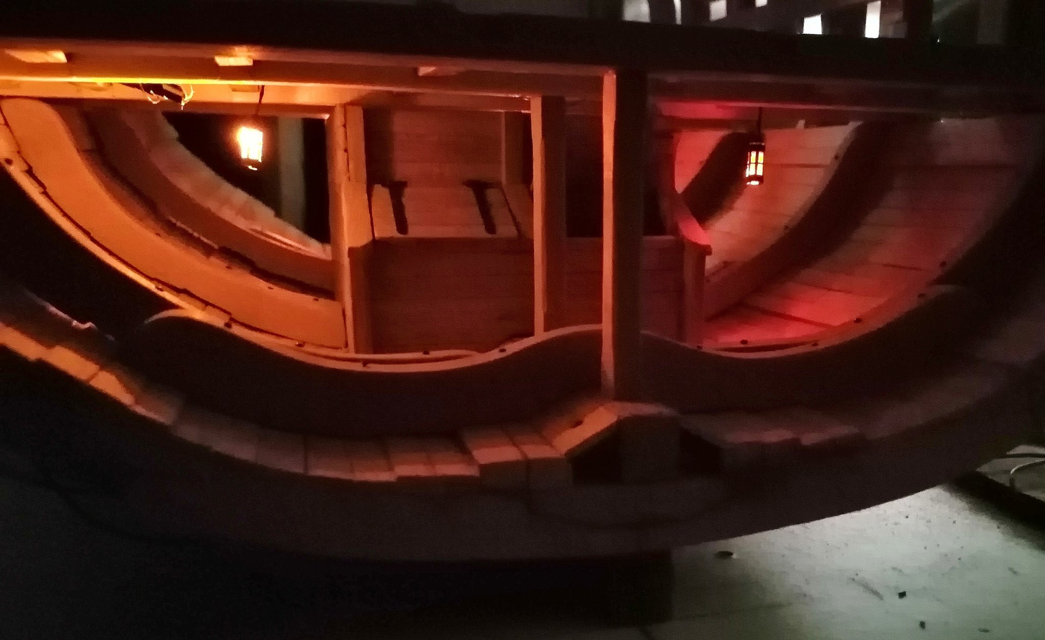
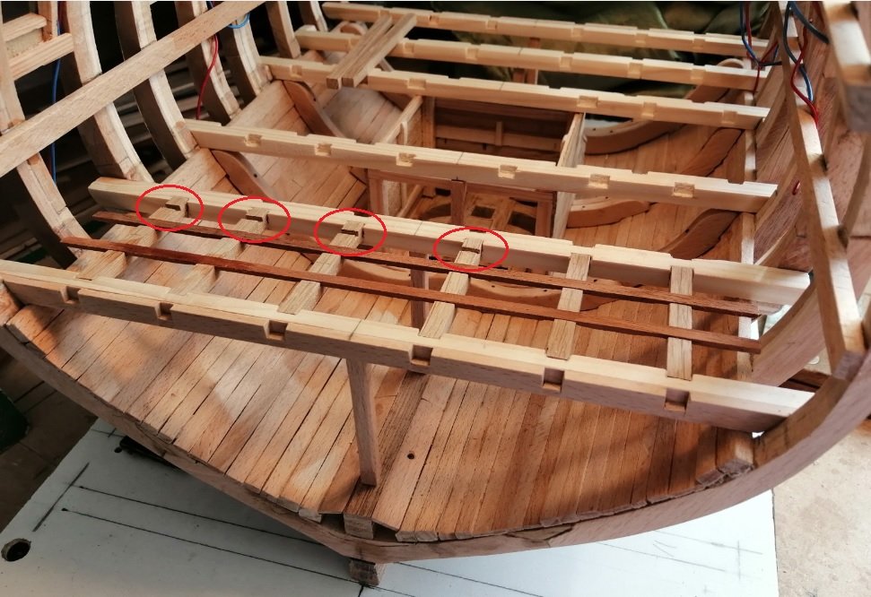
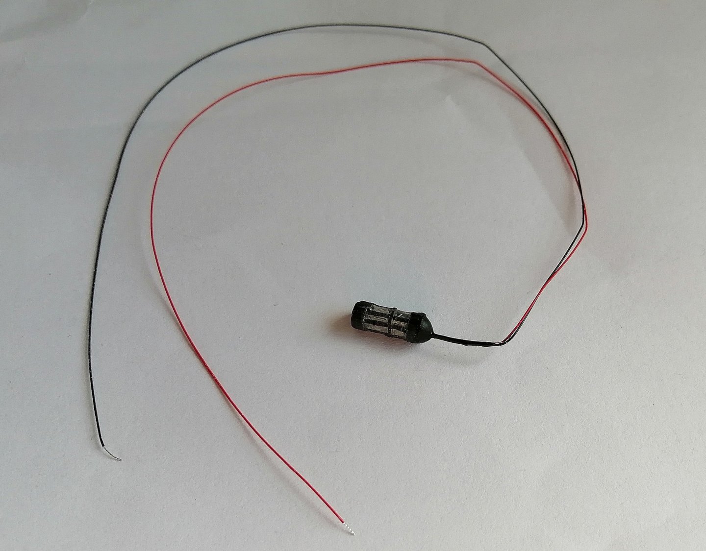
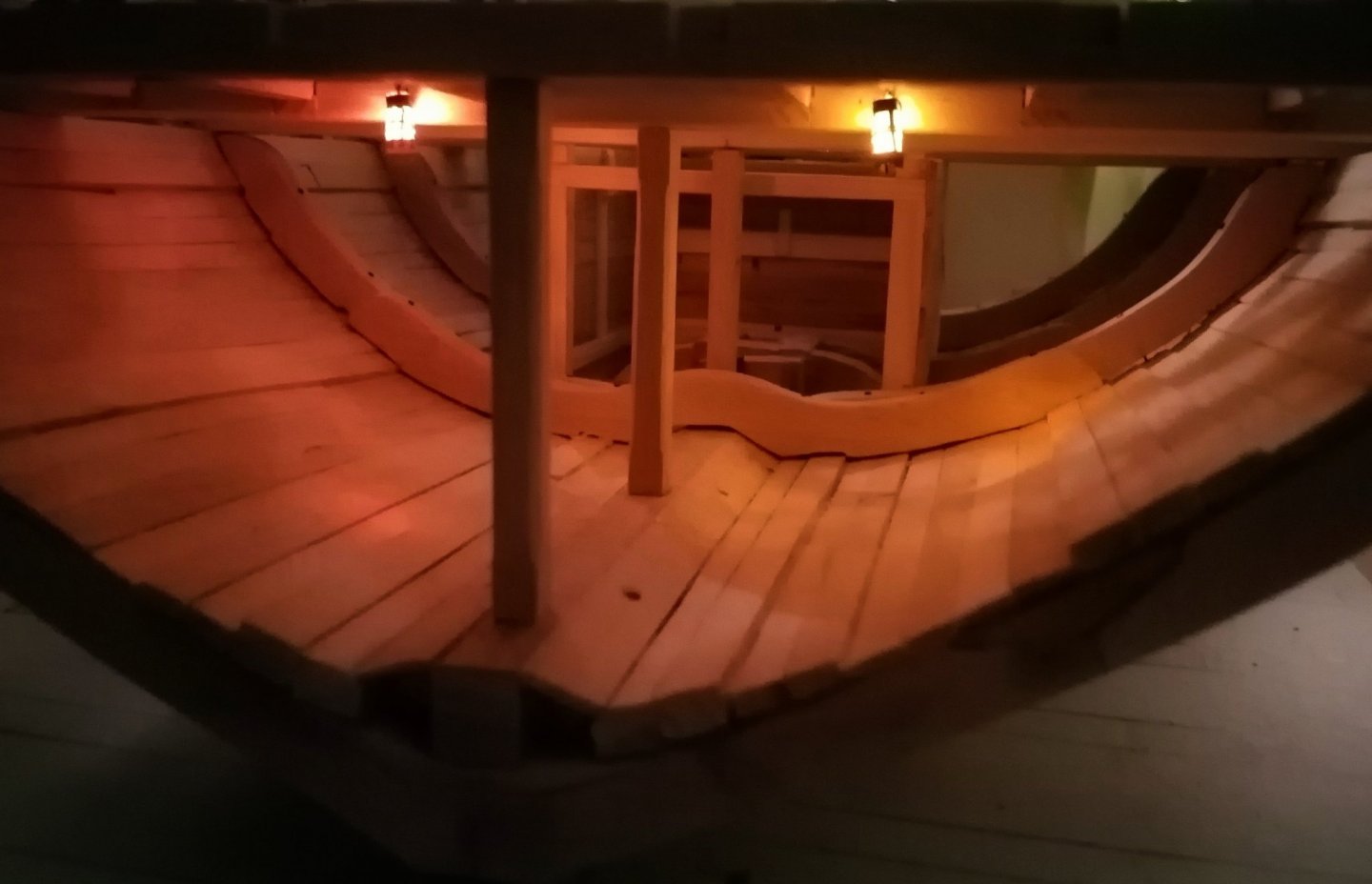
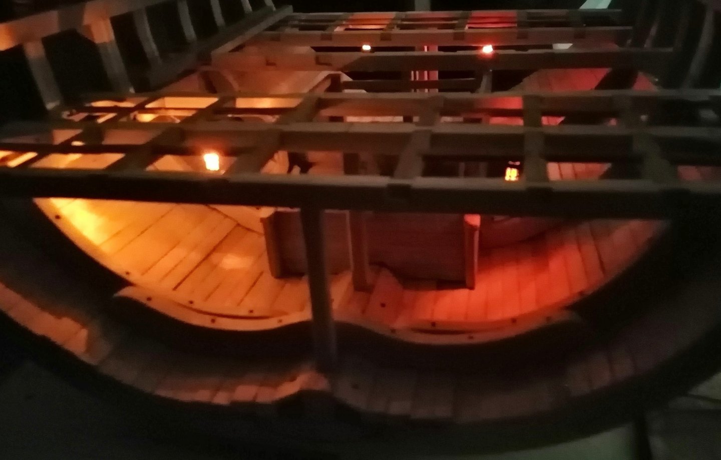
Pressed on and got the carlings and ledges finished. I cheated a little with the ledges in the two aft sections and just made them full width. As the deck will be planked none of what lies beneath will be visible Previously, in post #16 above, I stated that I would have to wait until the inside hull planking is done on orlop deck before I could make the (upper) breadth rider sections. I changed my mind -- I reckoned it would be quite tricky getting the exact profile on the riders to match the inner planking especially with all those carlings and ledges in the way. So I went ahead and fitted the final upper sections of the riders first. As far as I can see, there are no hanging knees for the orlop deck beams, only lodging knees. It didn't look possible to fit knees to the far side of that third beam (as seen from the view in the photo above) as the mid riders are adjacent to that face of the beam, so I had a try at opposing knees for that beam and the one nearer. By the time I had done the carlings and ledges, and also before I had fitted the upper breadth riders, I wanted to get the 4 hold lanterns fitted. That job was very tricky as it was, and I expect it would have been virtually impossible with the orlop deck planking in place. I used the milling machine to run grooves in four of the carlings as shown circled in the following photo. These grooves were for the wiring of the two aft hold lanterns. I hope to have around 18 lanterns eventually with 4 on most levels. So far, only made 4 lanterns. Made from 3mm O/D clear tubing with a Pico LED light held inside with a spot of glue, black paper strips glued on to simulate the frame. The wires on these lights aren't much thicker than a human hair and are very difficult to work with. It's not possible to strip the insulating cover from the wire -- it has to be burned off. I checked and double checked that each light was working before fitting them as once they're fitted, that's it - no going back. If they ever need replacing I'll have to recruit some of the 'little people'! The aft lanterns. The fore lanterns. . . . and the "four" lanterns.


-
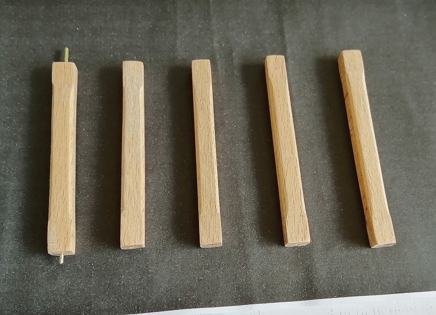
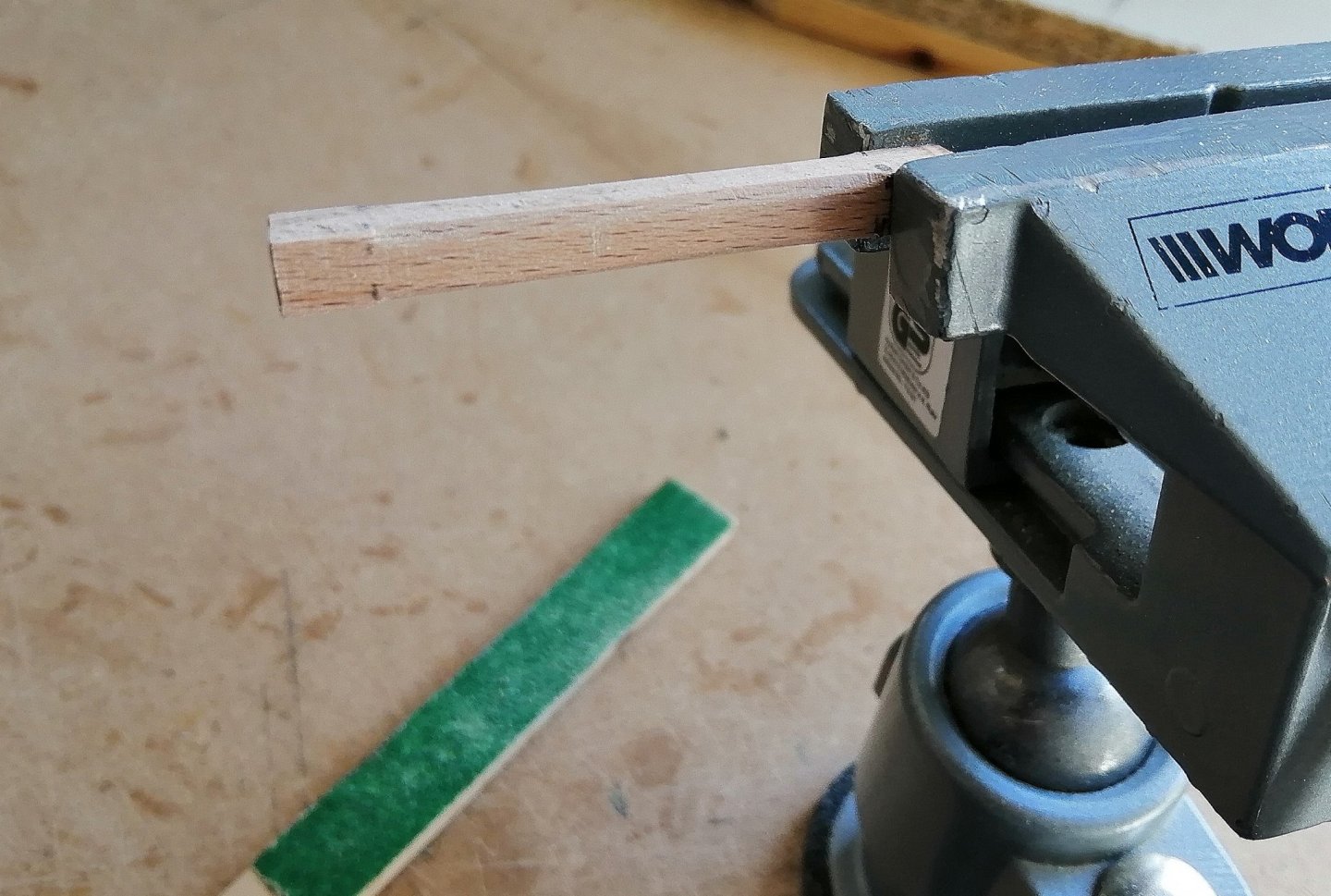
Time to secure the beams so some pillars required. Being square in section these were fairly straightforward -- just had to create a stopped chamfer on the corners of each pillar. Just clamped each in the vice, held the other end in my hand and made the chamfers with a sanding stick. Drilled a 1mm hole in the centre of the top and bottom of each pillar and a corresponding hole in the underside of each beam and down into the keelson and used small pieces of 1mm brass wire to ensure they stayed where they're meant to be. First two beams and pillars in place. Then all six. Six beams but only five pillars. The shot locker/lower well took care of the 'missing' pillar. Apart from a few areas, the whole of the orlop deck will be covered so what lies beneath the planks won't be seen, so as this will be my first time at creating anything like proper beams, carlings, ledges and knees I'm using this deck for a little experimenting. The photo above shows carlings between the first 2 beams and an attempt at a couple of lodging knees. The next shows my first attempt at ledges. When I began to cut the stopped mortice for the ledge in the left-hand knee I started at the wrong side ~ so the stopped mortice became a through mortice! The "hole" in the centre between the two beams (where there is no ledge) is for a future grating.


.jpg.1bdda804a3f798e99f51e9de15250d51.jpg)

.jpg.514b276191b8a78f2b463f10da064f47.jpg)
.jpg.ed17ee4313c227e6abf58a5a5e2580bd.jpg)