MORE HANDBOOKS ARE ON THEIR WAY! We will let you know when they get here.
×


Bluto 1790
-
Posts
324 -
Joined
-
Last visited
Content Type
Profiles
Forums
Gallery
Events
Everything posted by Bluto 1790
-
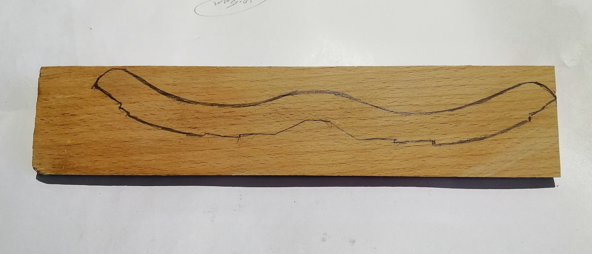
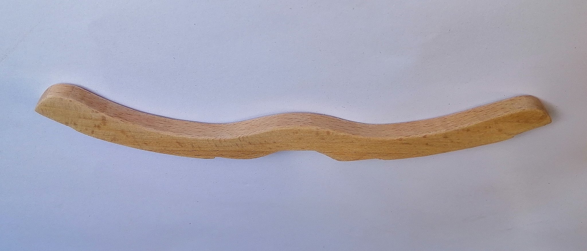
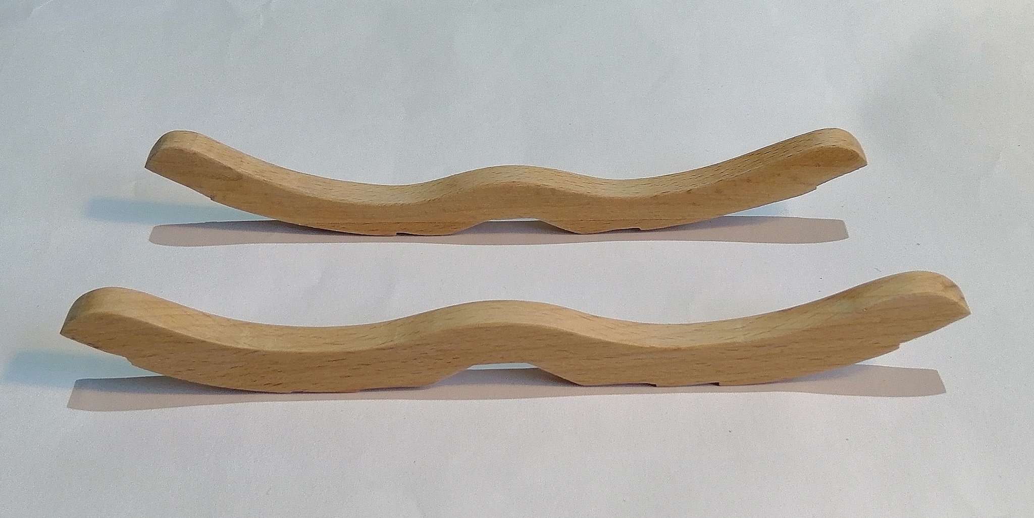
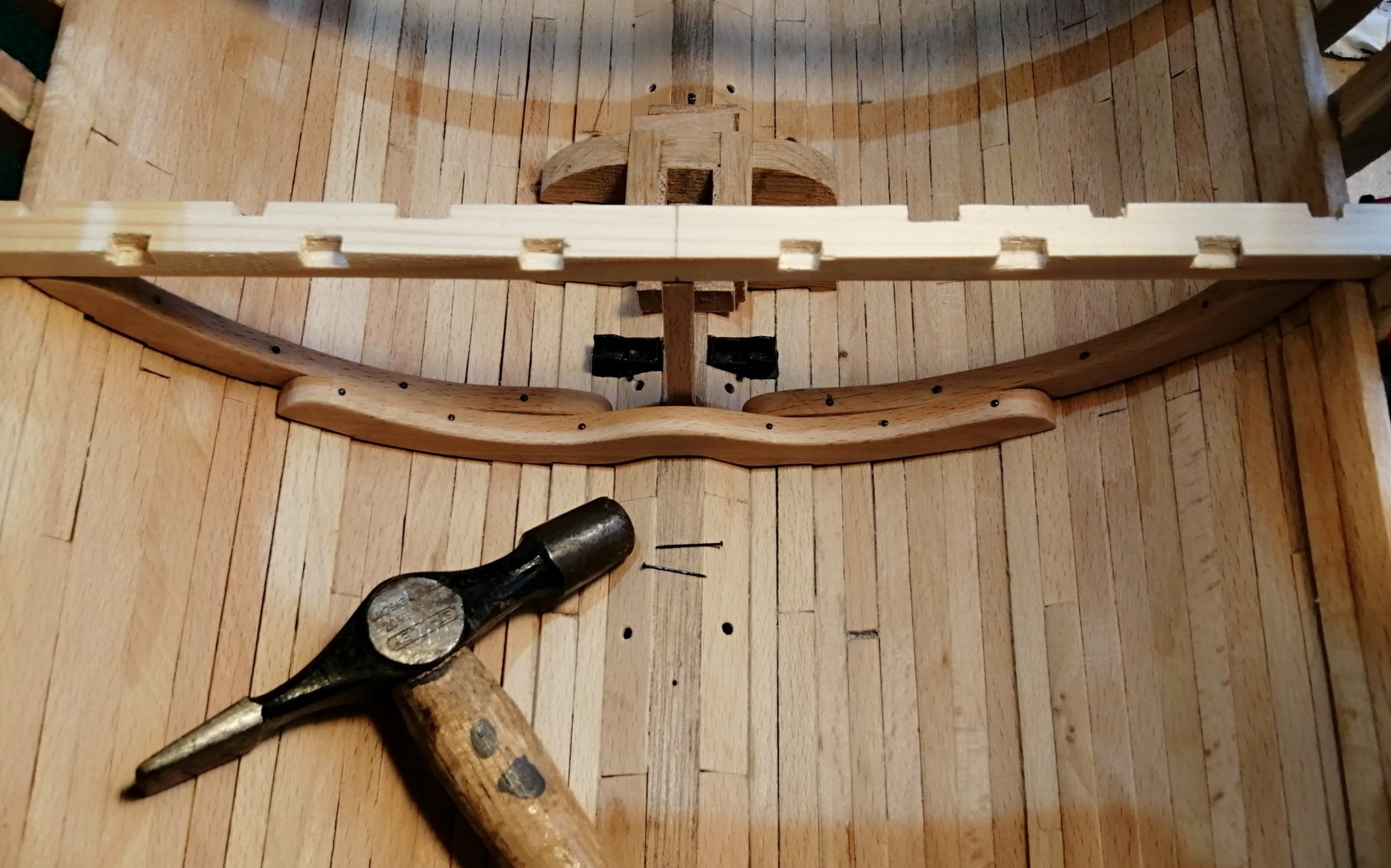
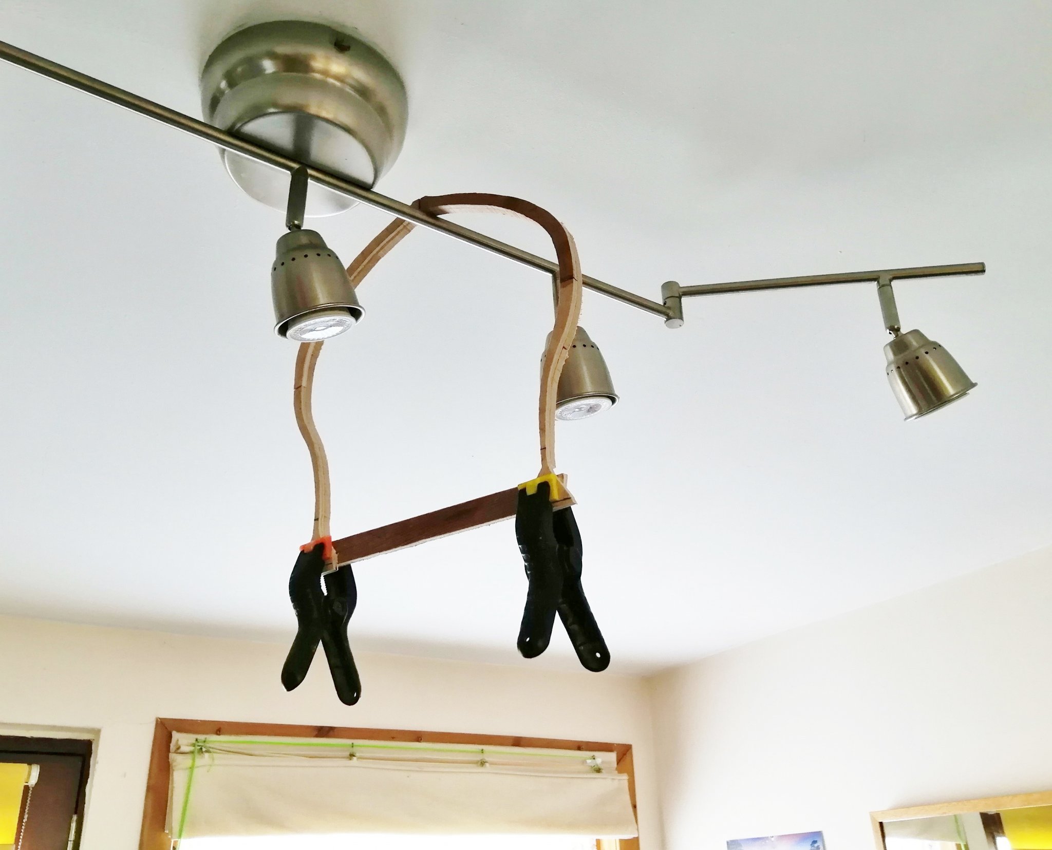
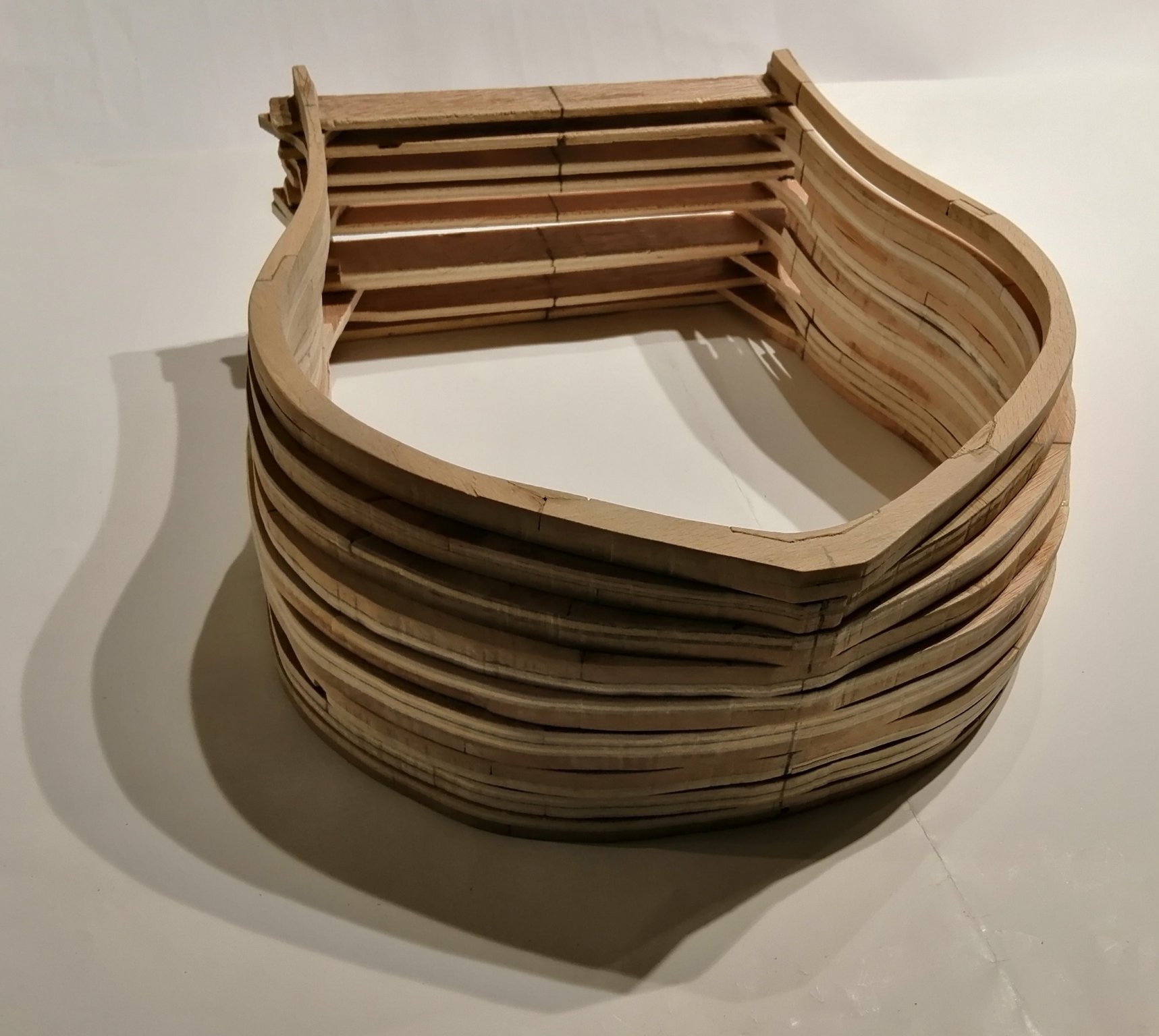
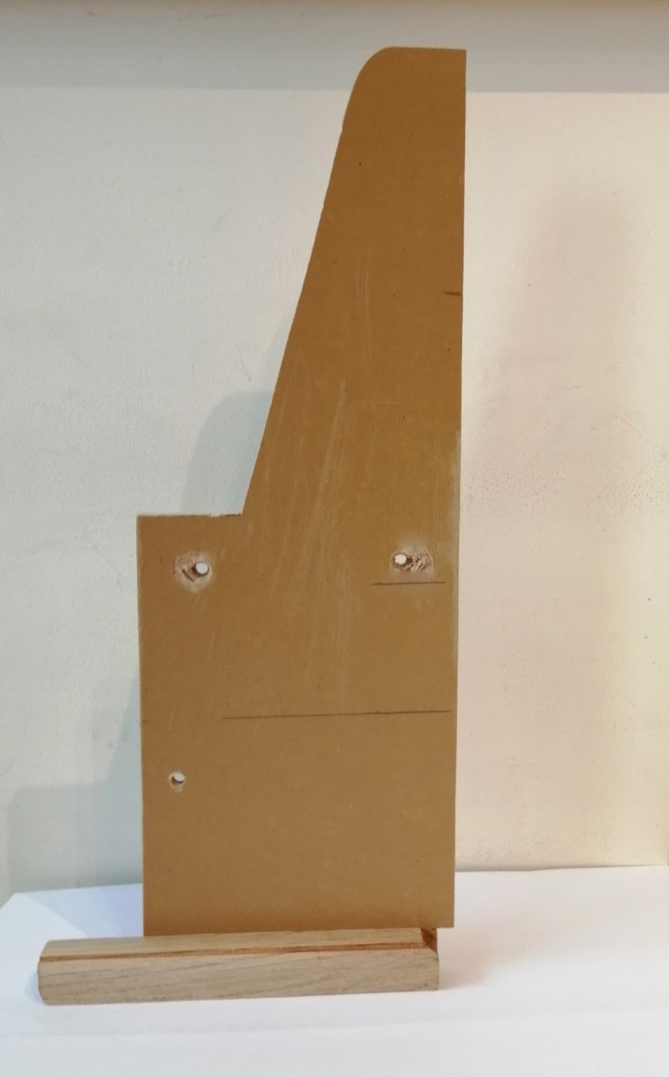
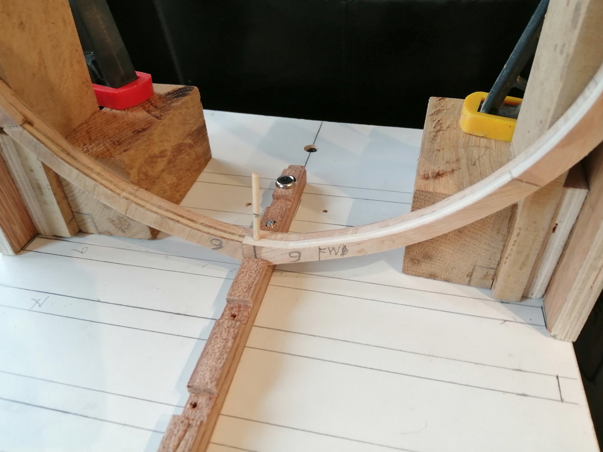
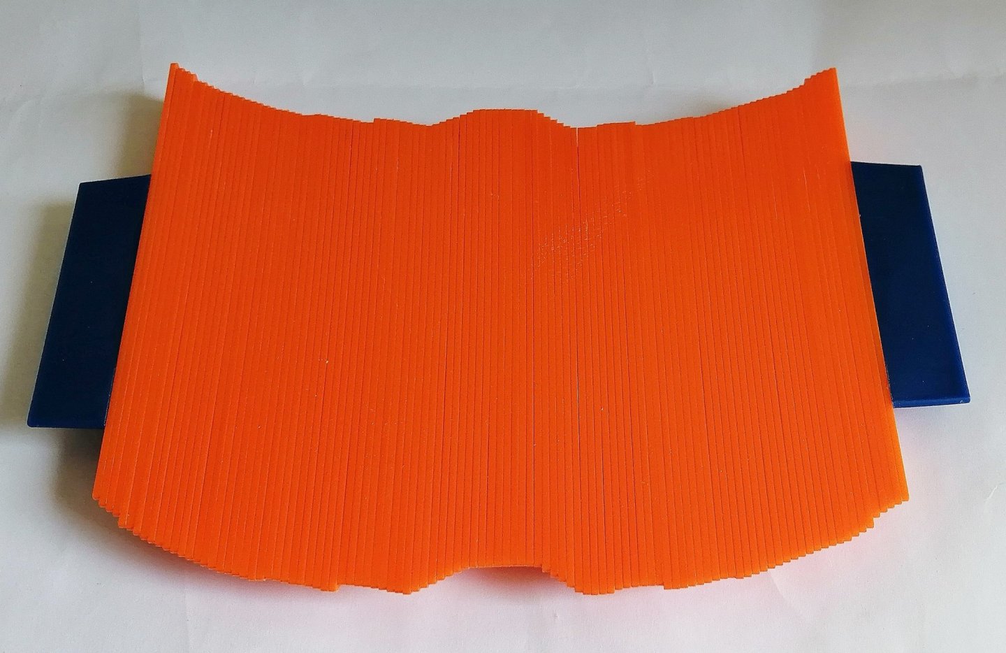
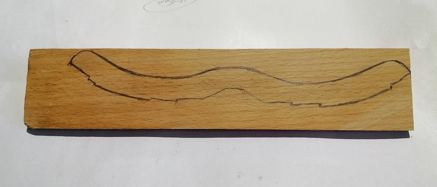
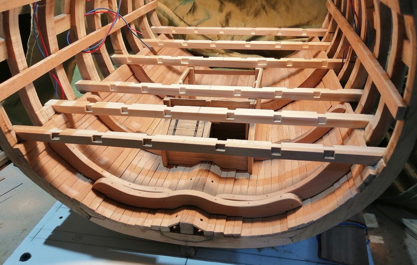
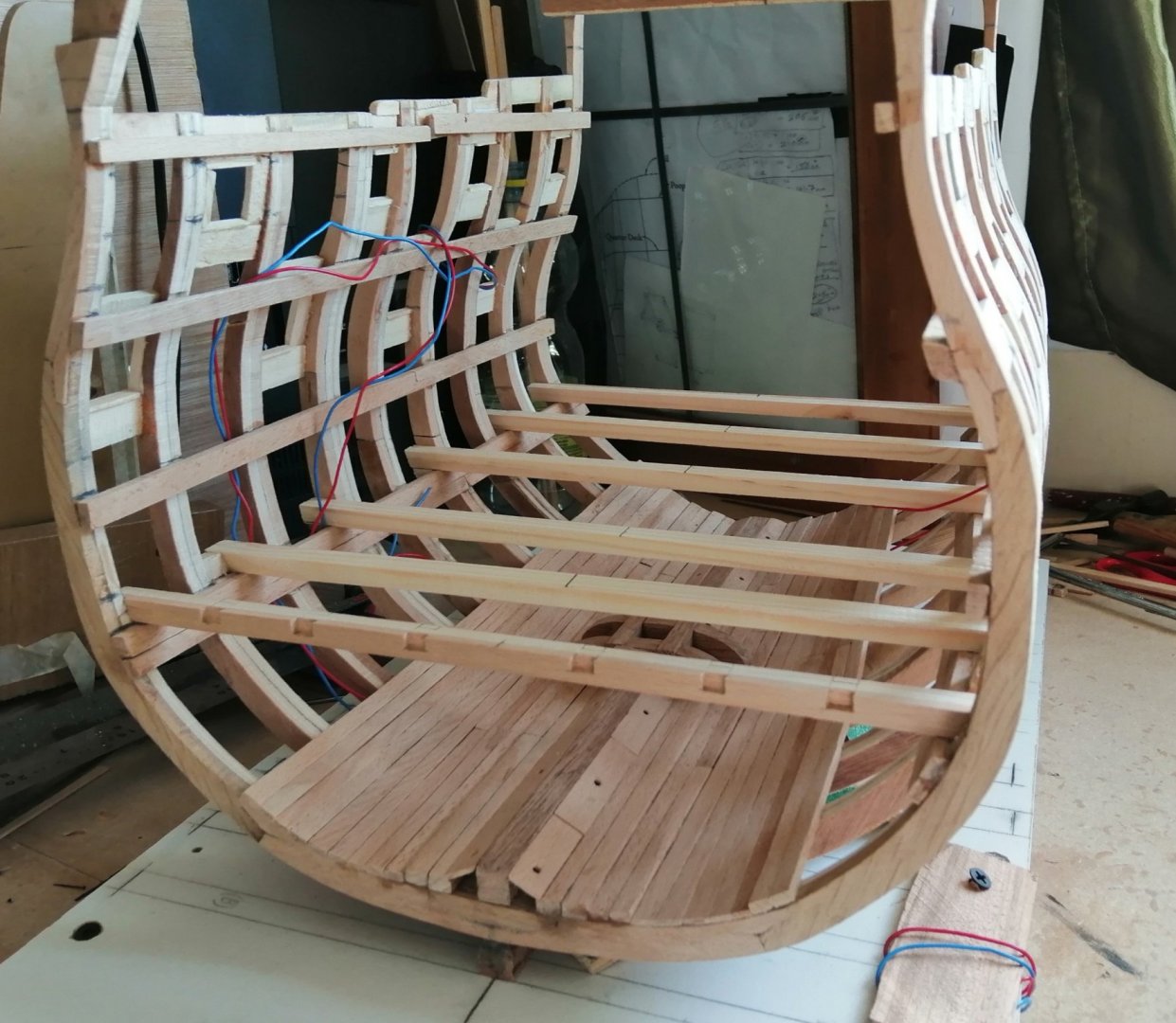
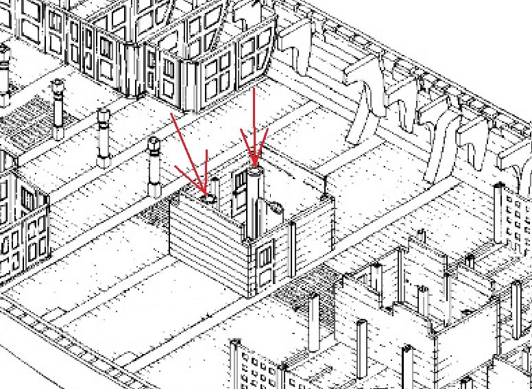
 Thanks for your further comment, Michael. Although the orlop deck beams have the mortices for the carlings cut, the carlings and ledges won't be cut until the hold is completed. A fairly substantial part of the hold are the riders. Very little - almost nothing - of the riders is shown in the drawings, and in fact, there is nothing of them in the 50 Gun Ship book. Only the section drawing that I posted at the beginning of this thread shows their approximate shape, and one other drawing of the orlop deck gives a few clues as to their positions. Here's that drawing, in which I've indicated in red what appears to be five riders, and only the three aftmost of these will occur in the section I'm building. I've arrowed these three riders > I started using card trying to get the profiles and after a few pieces of card got the first one fairly close -- then I bought this > That made it much easier and quicker to get the required profile which was transferred to card, tweaked a little then transferred onto the wood for cutting out on the bandsaw > The aftmost of the floor riders > . . . and with the foremost of the three > The first test 'ride' of the three floor riders > The orlop drawing above appears to show that middle rider just a little ahead of the main mast, and as such, looks like it would pass through the shot locker, so I cheated a little with that one and made it in 2 pieces. Here it's shown with the first futtock riders > Here, with the aft rider and both with their first futtock riders > All three with their futtock riders get a test 'ride' before permanent fitting < Well, need to get the orlop beams on so time to make these riders a permanent part of the ship. Aft rider glued and nailed on (deck beam just clamped on in order to get the rider in the correct position) > Riders and beams get to be together in the same hull (beams still just dry fitted here as the support pillars are still to be made) > Will have to wait until the inside hull planking is done on orlop deck before I can make the (upper) breadth rider sections.
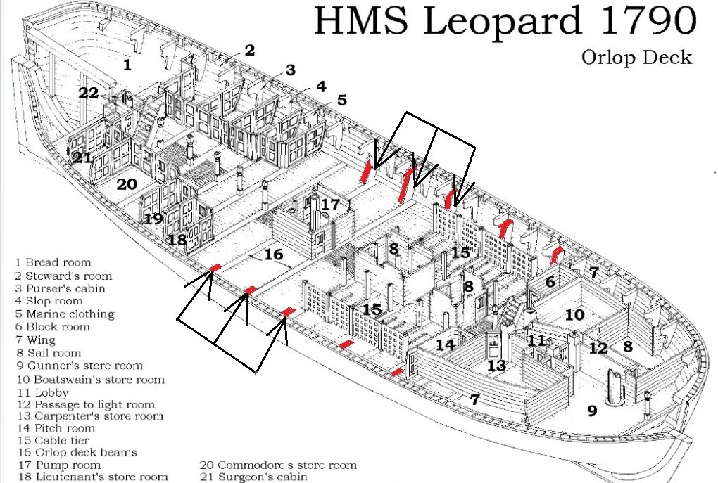


- 66 replies
-
- 11
-

-
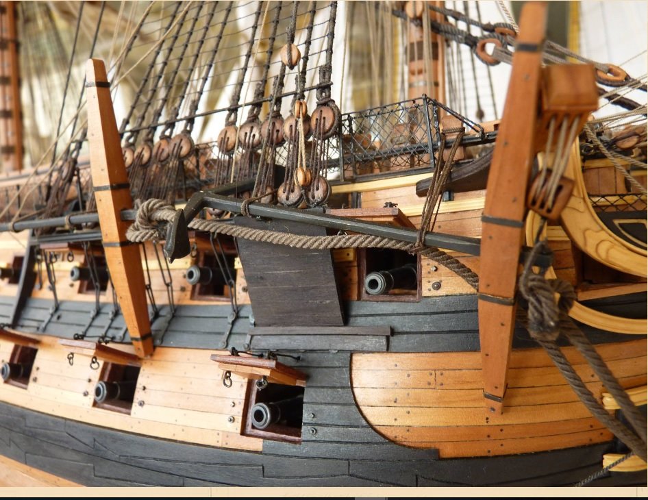
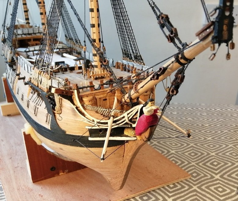
Hi Tom, While I personally can't give a definitive answer to your question, I would just say to you what I find I have to say to myself frequently while trying to find accurate information about these 50 gun ships ~~~ and that is, there is a lack of complete information on quite a few aspects of the build features of these ships and for some things I have to 'make it up as I go along'. That doesn't mean that I just do any old thing! . . . but I find I have to adapt features from other ships from the same time period. I tried googling for the date of the introduction of sheer poles but google didn't know. I would just say "do what you feel you want to in the absence of firm evidence one way or the other." Here's a photo of a model of Leopard showing sheer poles on the foremast shrouds -- but I'm guessing that modeller made their own conscious decision about whether or not to include them. (This modeller fitted sheer poles on all masts.)
-
Thanks Michael for the comments and the others for the likes and looking in. Michael, you're right ~ the big scale is very nice to work with. My other build was only about half of that scale and there sure were plenty tricky things to work on there! Although the other one was a complete ship, it was a bulkhead model so there are so many things that I'm facing for the first time with this build as, below the lower deck on the other build there was nothing like there is on this one. You asked if I'll be adding 'filler' material on each deck, and yes, I'm pretty much trying to get each deck complete before moving up. I've already found your cross section build log and have been through it several times! ~ It's something of a tutorial for me in this section I'm doing. There are so many great ideas on your build that I've got it earmarked! I'm about to make a start on doing some lanterns . . . and guess whose method I'm copying? !! I'm a bit of a prowler, looking through so many build logs trying to get ideas . . . and there are plenty of them!
-
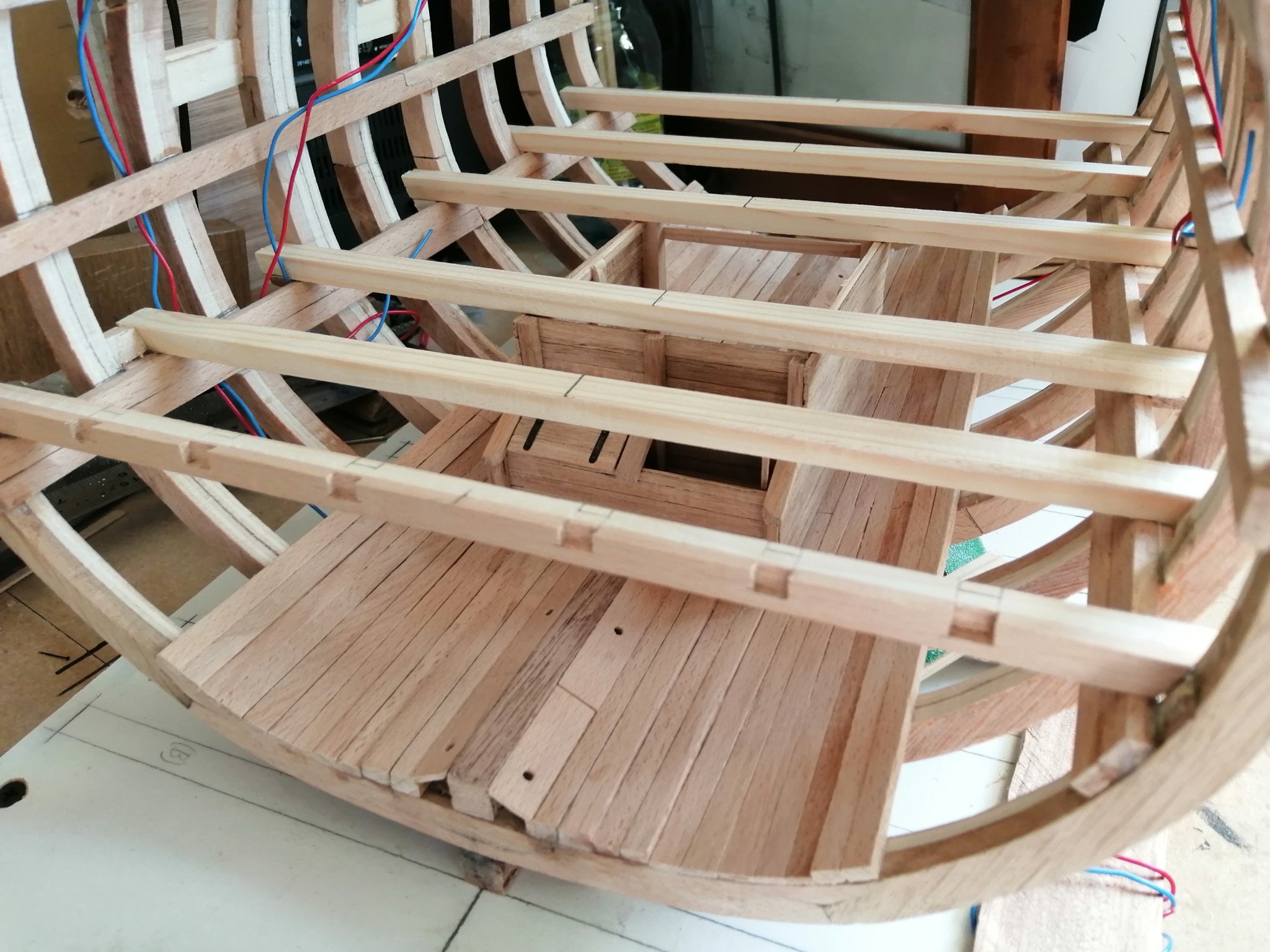
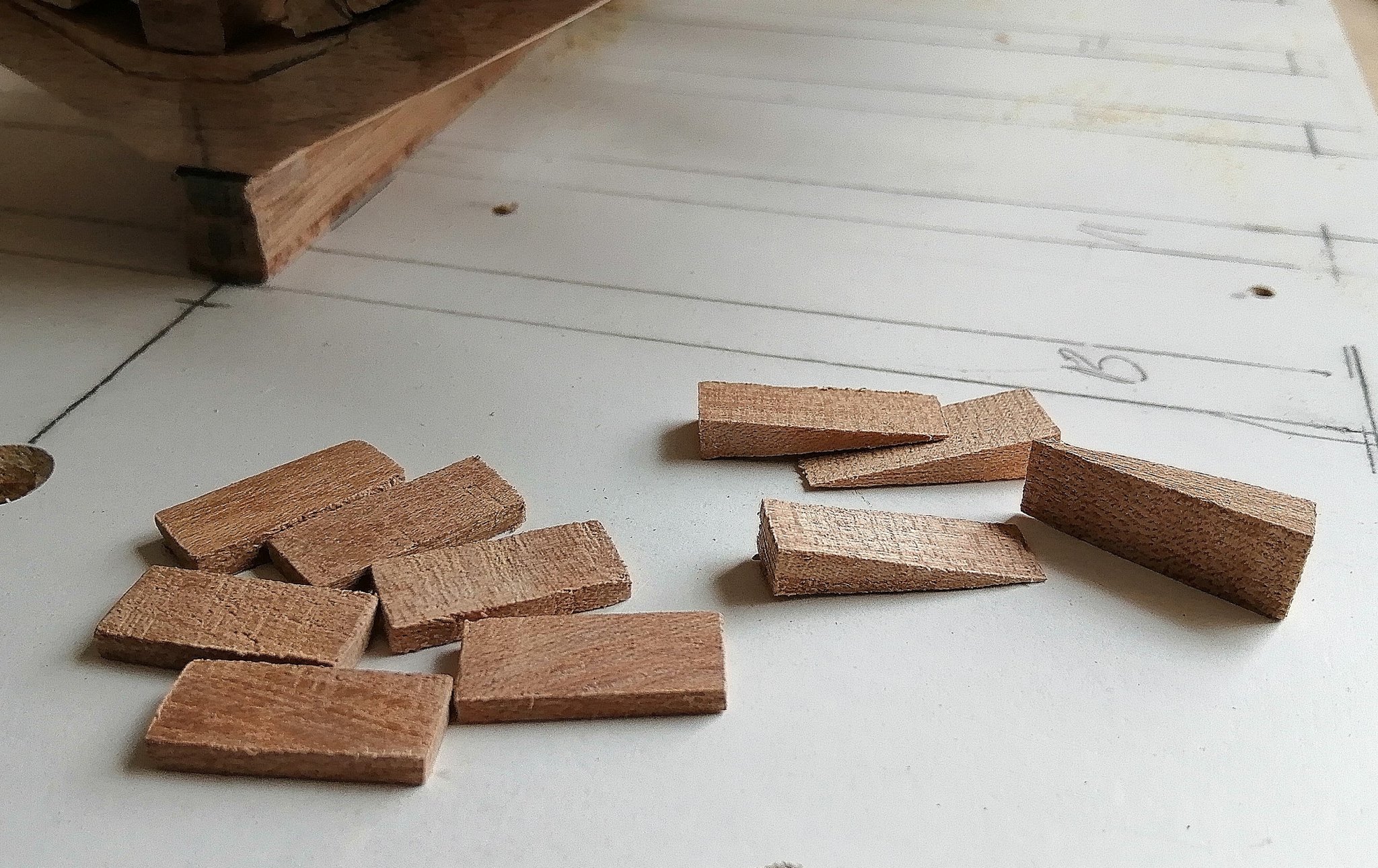
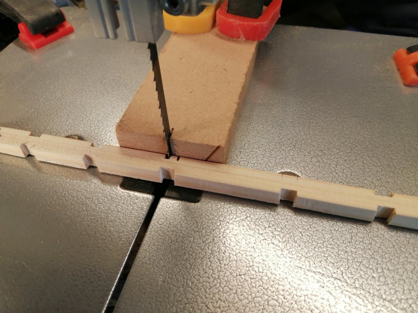
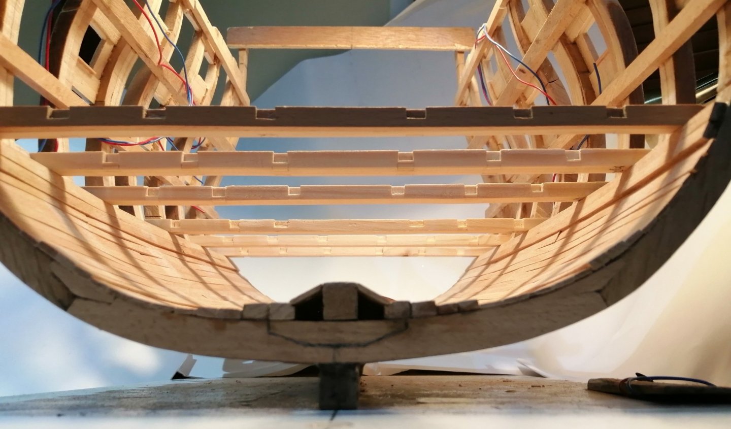
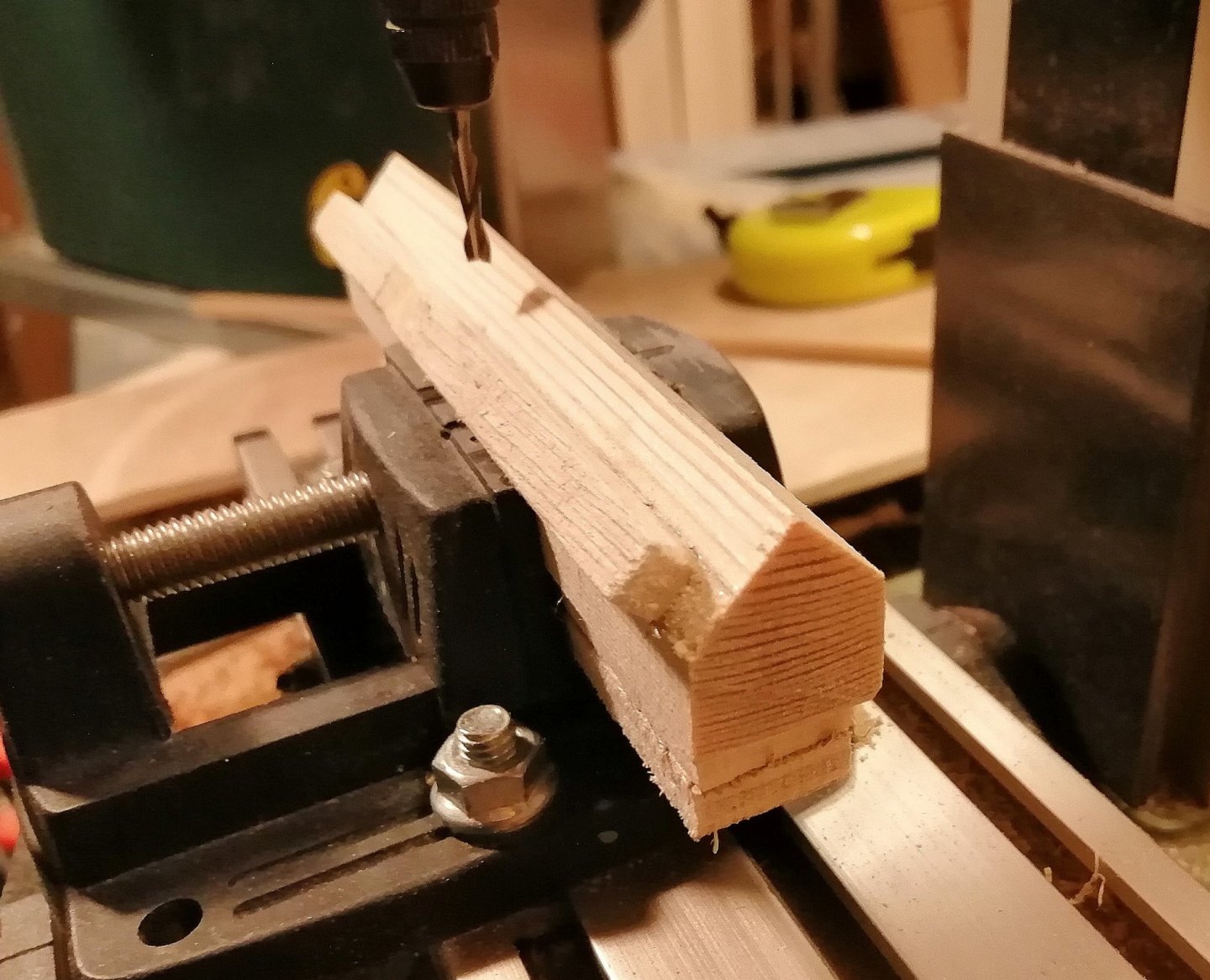
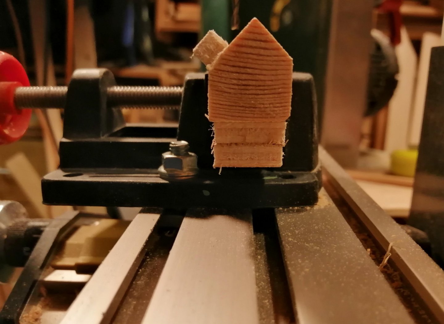
Another 'side project' I did while the hold planking was being done was to make the 'easy' orlop deck beams. 'Easy' as they're flat without camber. Dry fitted > Only the outside faces of the two end beams were beech; the other 4 beams I made from softwood as I'm trying to stretch out my dwindling supply of beech as the lockdown continues and no timber merchants are open yet. In the photos above only the closest beam had had the mortices cut for the carlings. I cut these with a 3mm chisel but cutting the softwood beams left the edges a little less sharp than I hoped for, so I completed these on the bandsaw. I used a stop block clamped around and behind the blade in order to control the depth of cut. As the bandsaw cuts the full height, I had to glue in fillers at the bottom of each mortice. Cutting off the excess and then some sanding, and the mortices looked acceptable. and back in for a second dry fit before going in 'the box' The positions and configuration of the beams, carlings and ledges, as well as knees will be a little bit of guesswork, as, to my knowledge, there exist no 100% accurate drawings and plans for these in any 50 gun ship. In particular, there is virtually no information about the hold area and very little about the orlop deck. I am basing a lot of what I am building on what I see on other build logs of English ships of a similar era. My aim is to finish with something that isn't a 100% accurate model (I don't think that is possible), but to end up with something that is reasonably representative of these 4th rate ships.


- 66 replies
-
- 11
-
-
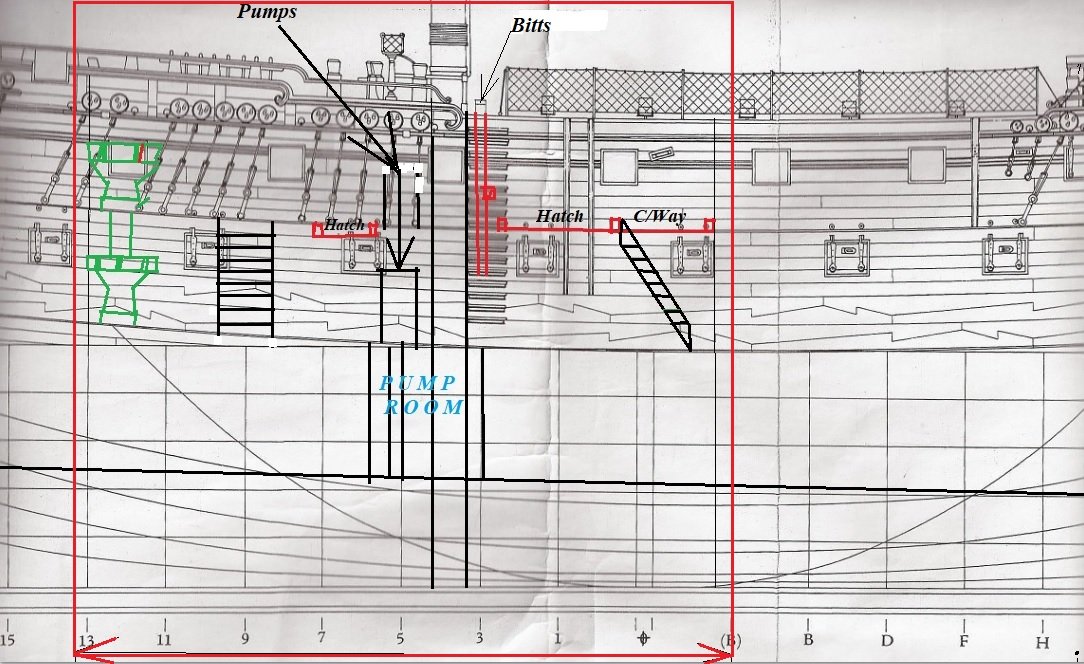
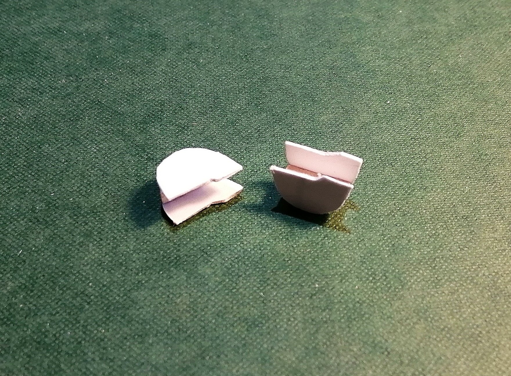
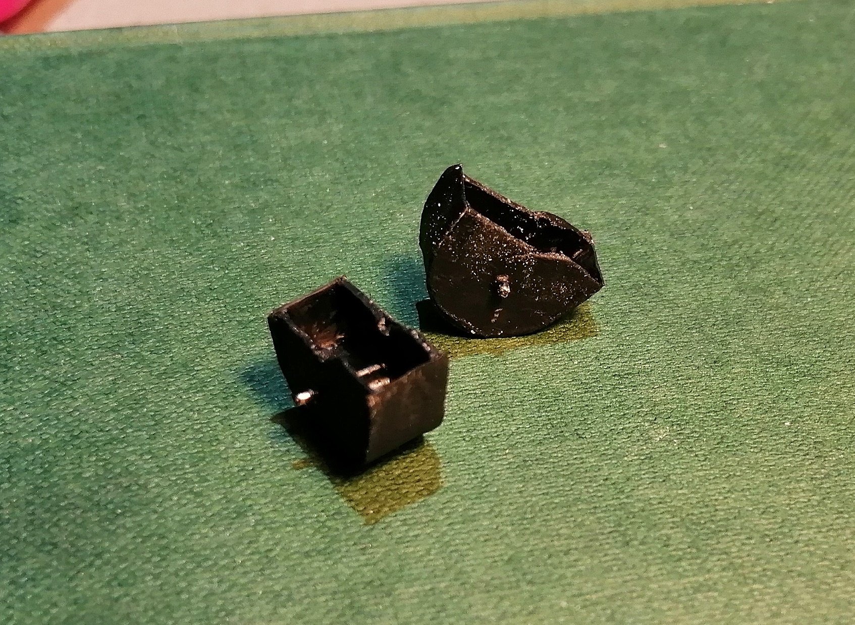
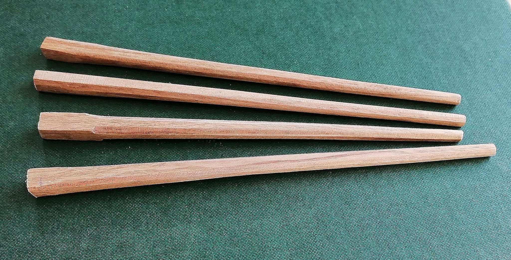
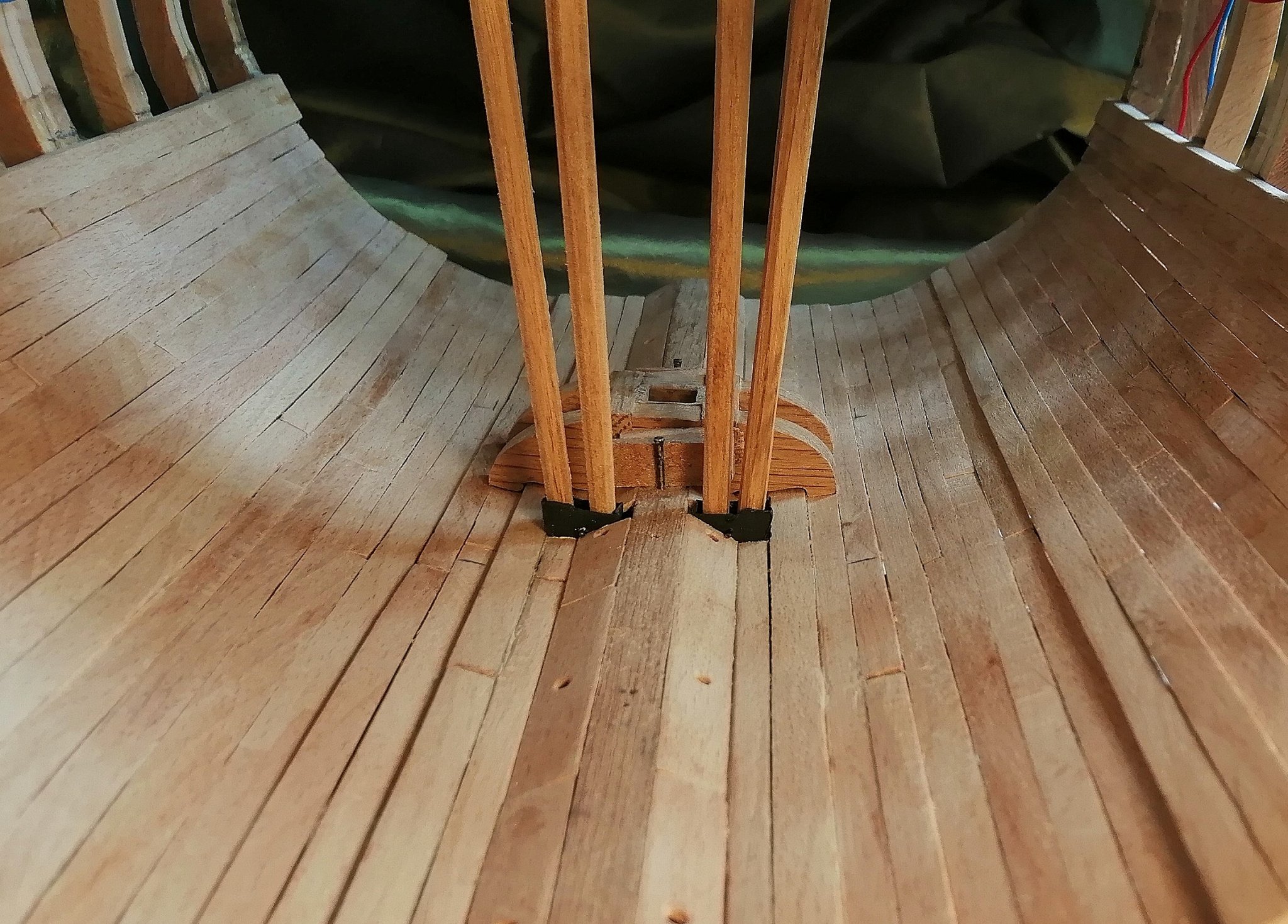
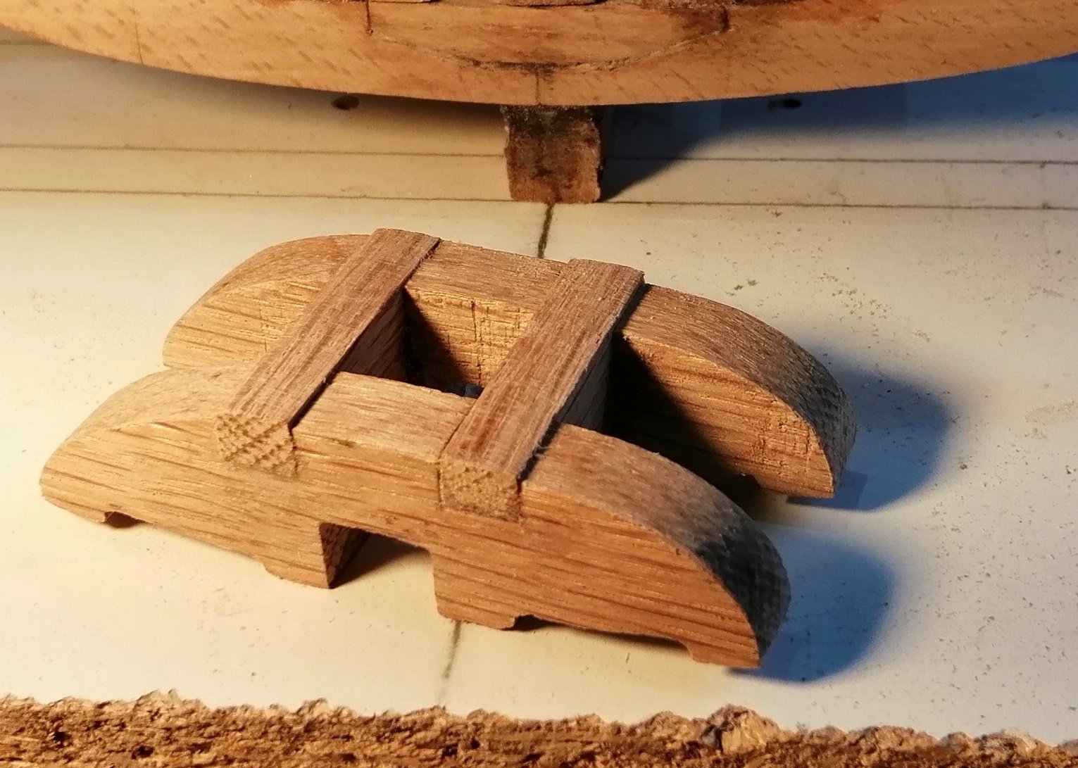
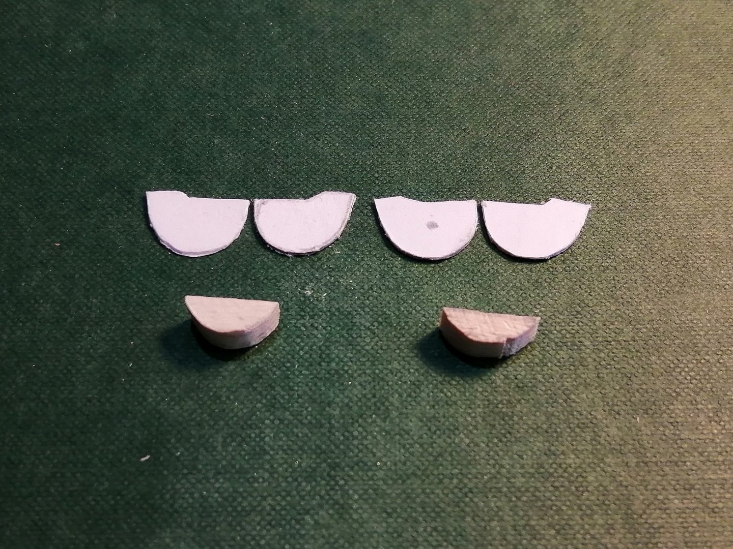
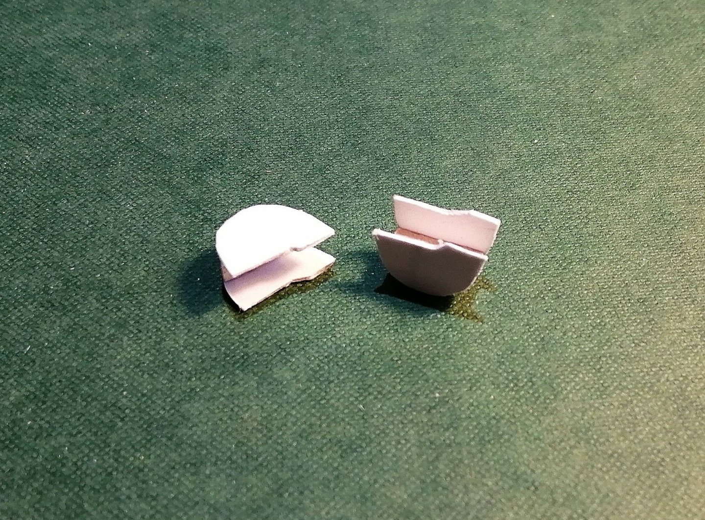
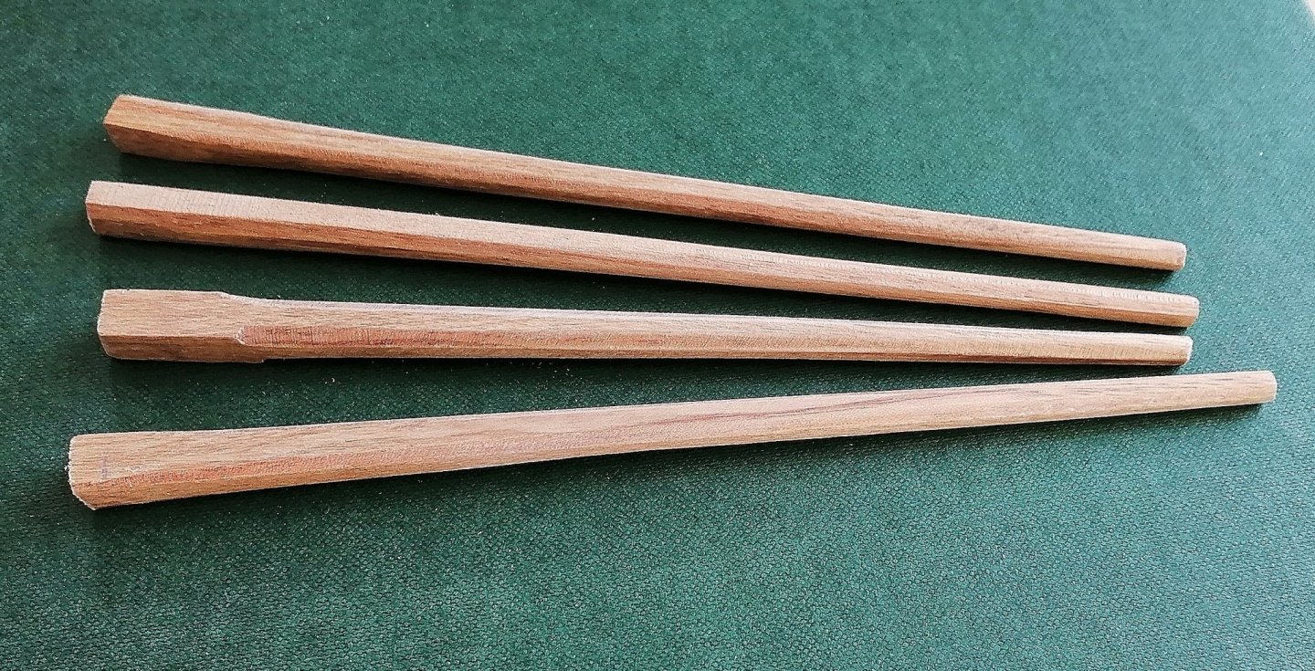
It may seem a bit early in this build to mention pumps - - but while sailing ships wouldn't go anywhere without sails and would be fairly uncontrollable without a rudder, without pumps they wouldn't stay afloat for very long. This, being a section, won't have sails nor a rudder so I thought at least it should have pumps. Just a few weeks ago I knew very little about pumps but my research and asking questions has turned up some good information although it wasn't the easiest to find. The Elm Tree pumps: Neither "The 50 Gun Ship" book nor any of the plans/drawings I have of the 50 gun ship make any mention of these pumps. In one answer to my question on Google , one "knowledgeable" person said these were the chain pumps -- that is INCORRECT -- the chain pumps are completely different. The elm tree pumps (or brake pumps) were used to draw water either directly from the sea (by means of a "hole in the hull") or from a watertight cistern in the hold which was filled by drawing water in through the hull. The function of these pumps was to provide water for deck washing and firefighting if required. The Chain Pumps: The purpose of these pumps was to put water back where it is supposed to be -- in the sea. These were always located on the lower gun deck, or whichever deck that was the first above the ship's natural waterline. I'm guessing that to have added longer tubes to reach a higher deck would increase the length of the chain and, combined with the weight of the extra water that would be lifted, would add considerably to the already heavy load on the men working the pumps. Each type of pump had a different advantage over the other -- the chain pumps could lift large amounts of water in a short time but not under pressure, so were of little use for hosing decks or fires. The elm tree/brake pumps could deliver water under pressure and to higher decks but were considerably less efficient at drawing a large volume of water in a short time. I always try to think ahead in the build in my attempts not to have to do something that should have been done earlier - - well, I don't always succeed in that. While I was recently pleased to have finished all the internal planking in the hold, I've just had the minor inconvenience of having to cut through a couple of limber boards and strakes for the holes for the sumps of the chain pumps. These 2 cuts took the best part of 2 hours, including the repairs to a couple of the limber board and re-gluing them back in. Drills, mini saw, files and sandpaper later >> The 'metal' sumps I made from card and a little 'half-moon' piece of wood to hold them together > And a grainy photo of them painted and ready for the hull (I find it very difficult to get good photos of black or white items) > There aren't any inlet holes in these sumps as there won't be any water in the bilges of this model for the dummy pump tubes to draw up! The sumps dry fitted > And here are the dummy tubes (looking like 2 pairs of chopsticks) > These will be left oversize until I get up to working on the lower gun deck. I tapered these tubes by using the belt sander - - carefully. The octagonal shape was attempted by hand using a block sander. Here in 'test drive' mode > Next, the elm tree pump tubes . . .


- 66 replies
-
- 12
-
-
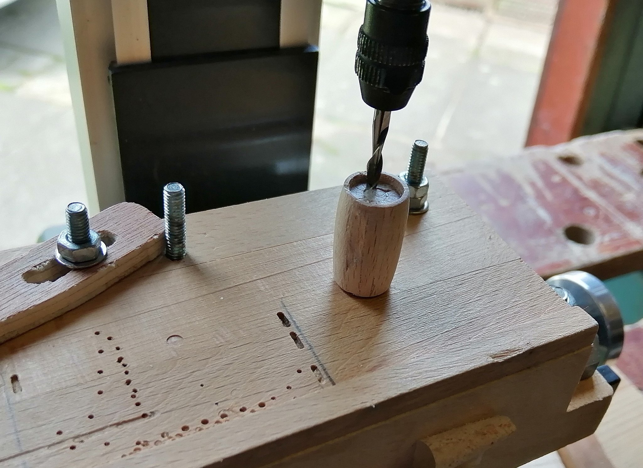
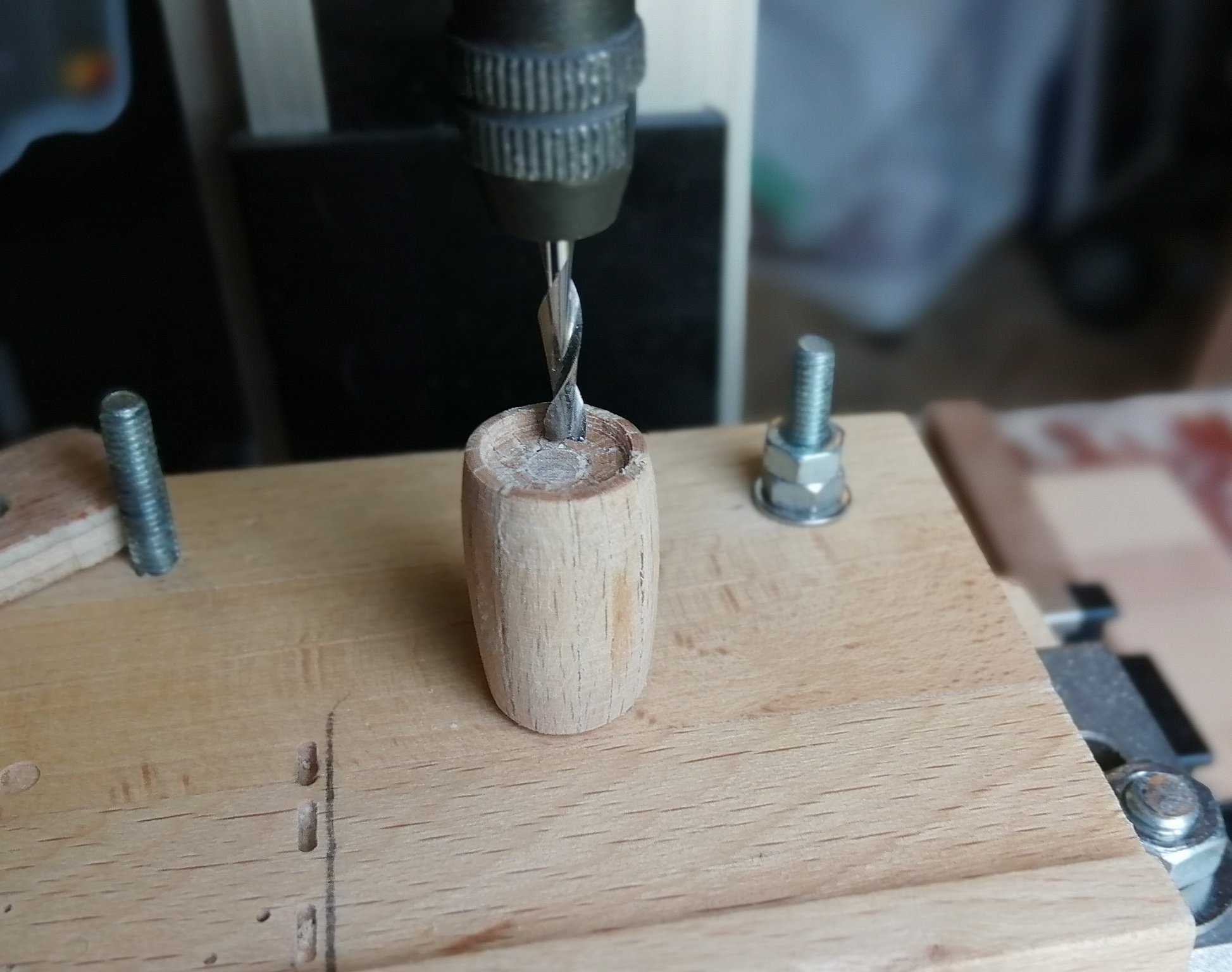
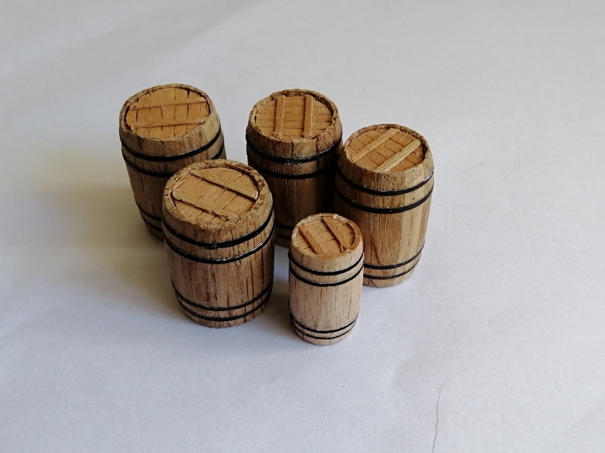
A week or so ago I reached a milestone in the build - - - I wouldn't really have considered it to be a milestone but it took me so much longer to complete than I had imagined it should have taken. I guess it was the 4 different thicknesses of the timbers that protracted the time I took to get the internal planking of the hold finished > I diverted to other small projects for the build during that time. In my other build there were lots of things that I didn't have to make as the model was fully planked and nothing below lower gun deck was visible, in fact only the guns were viewable on that deck. Nothing on the orlop deck or in the hold was made back then so this was my first attempt at making a barrel. I adopted a method I had seen on other builds for the basic blank for turning the barrels. This is the blank I used for the second batch of barrels > The first barrel I tried was made from a scaled down version of the above -- just big enough to make one small barrel > Although I was able to turn the blank on my lathe jig - I don't have a proper lathe, just a jig into which a drill fits, I wasn't able to hollow out the top on the lathe. I had to do that on the milling machine. The uncut dowel fits into a hole drilled in another jig I made to fit onto the mill table. > I don't move the table in the conventional way, but bring the cutter down to the barrel, move the barrel into the desired position by moving the table in/out and left/right until the cutter is where it needs to be. (These are the only movements made to the table.) I then slowly spin the barrel (with my fingers) on its dowel while the spinning cutter hollows out the top. I cut the outer ring of the hollow first (very carefully!) then carefully move the table around until all of the unwanted wood is removed > With lid > . . . and with a few bigger friends > That's 5 barrels done - - another 15 or 20 to go ?


- 66 replies
-
- 11
-
-
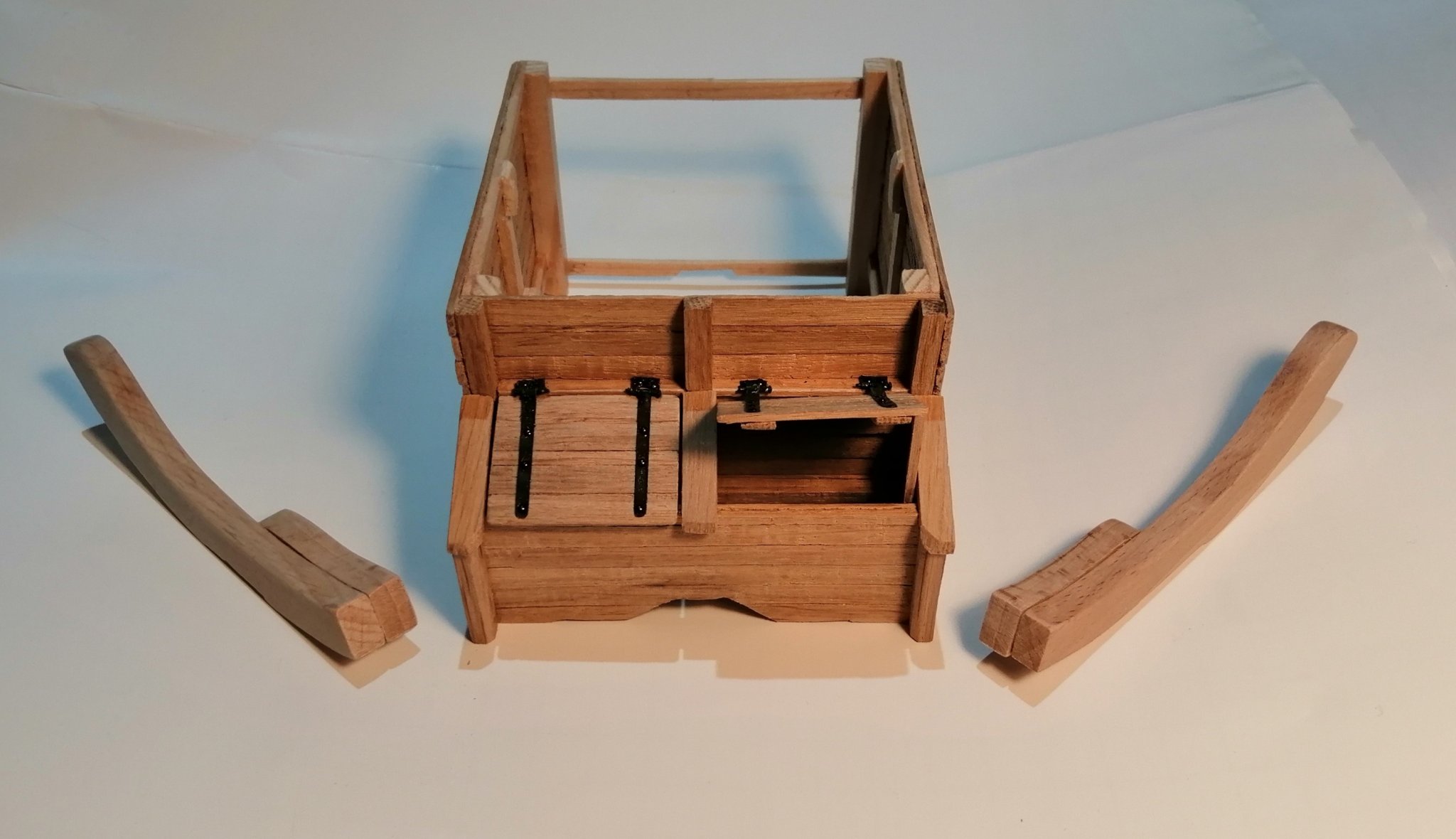
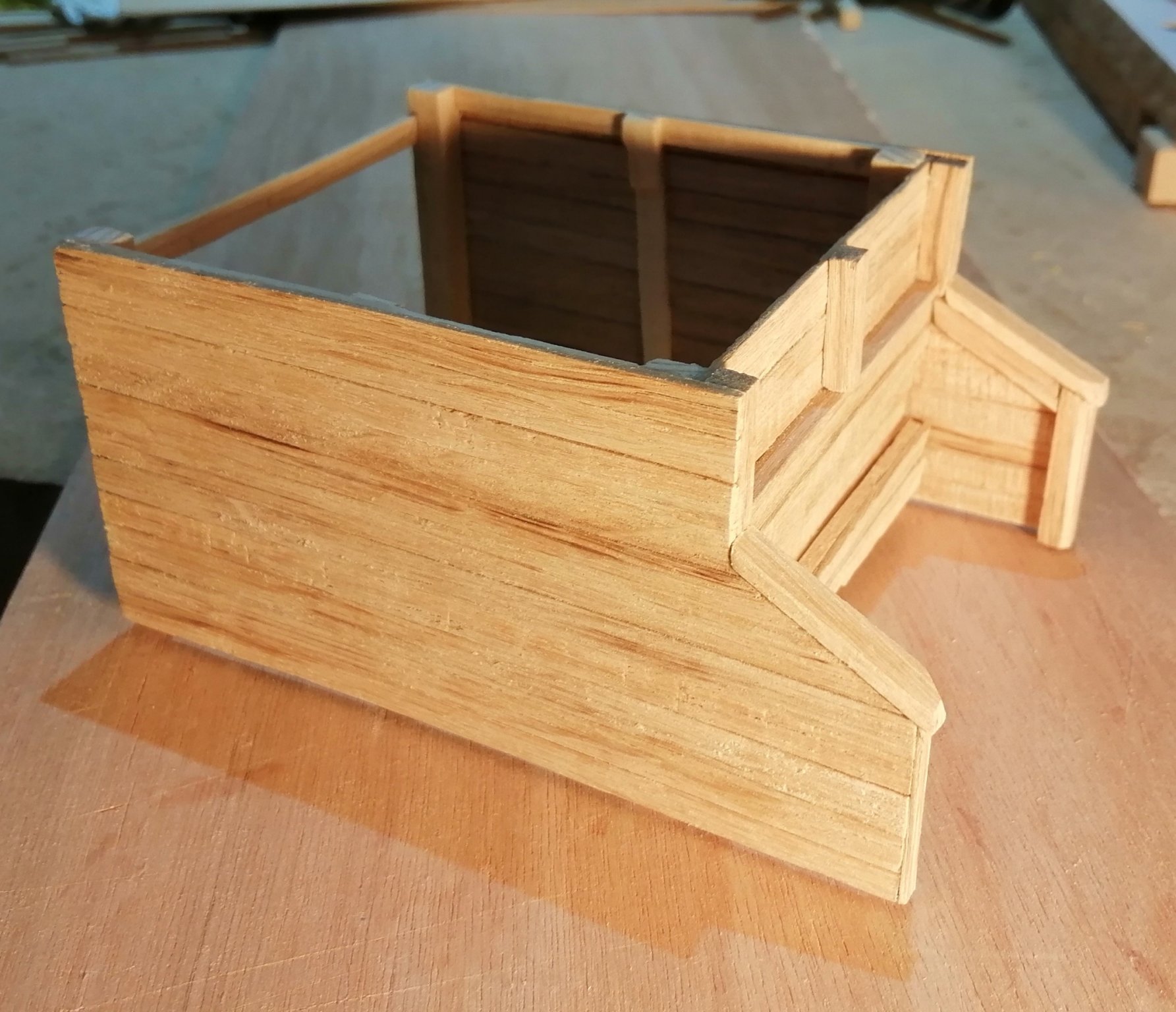
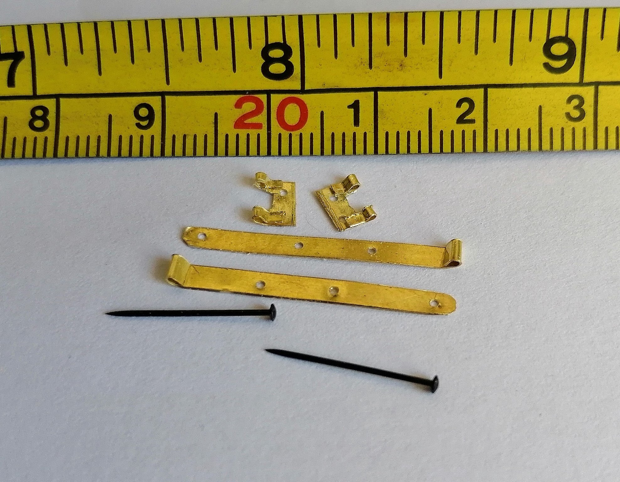
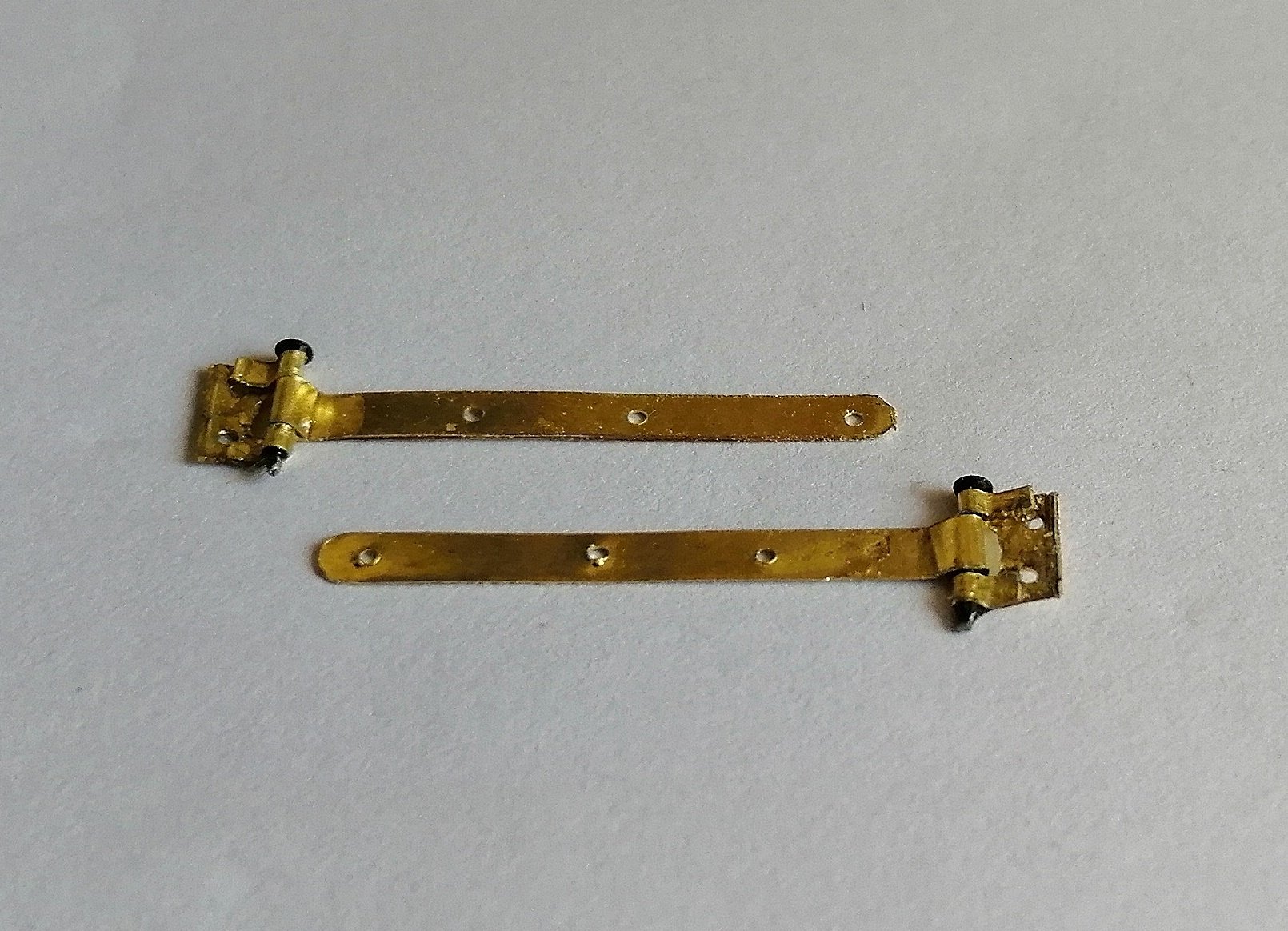
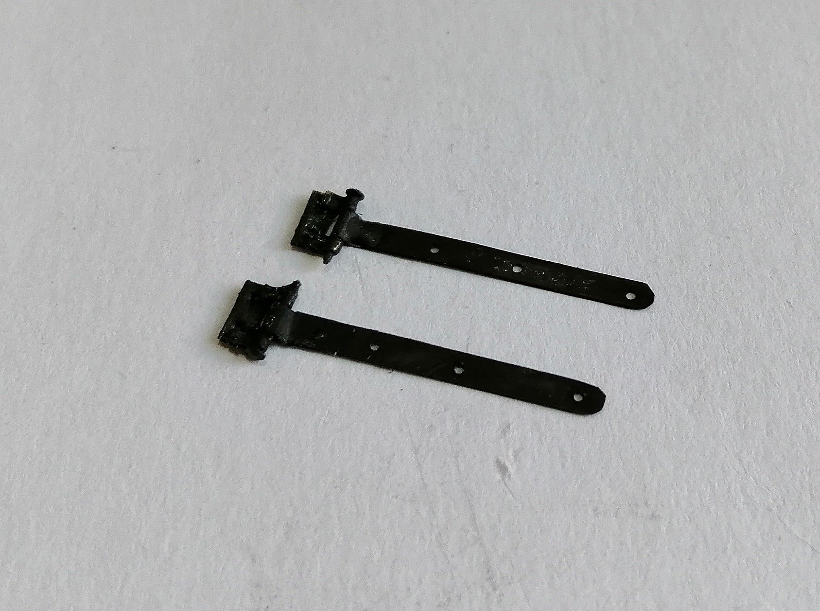
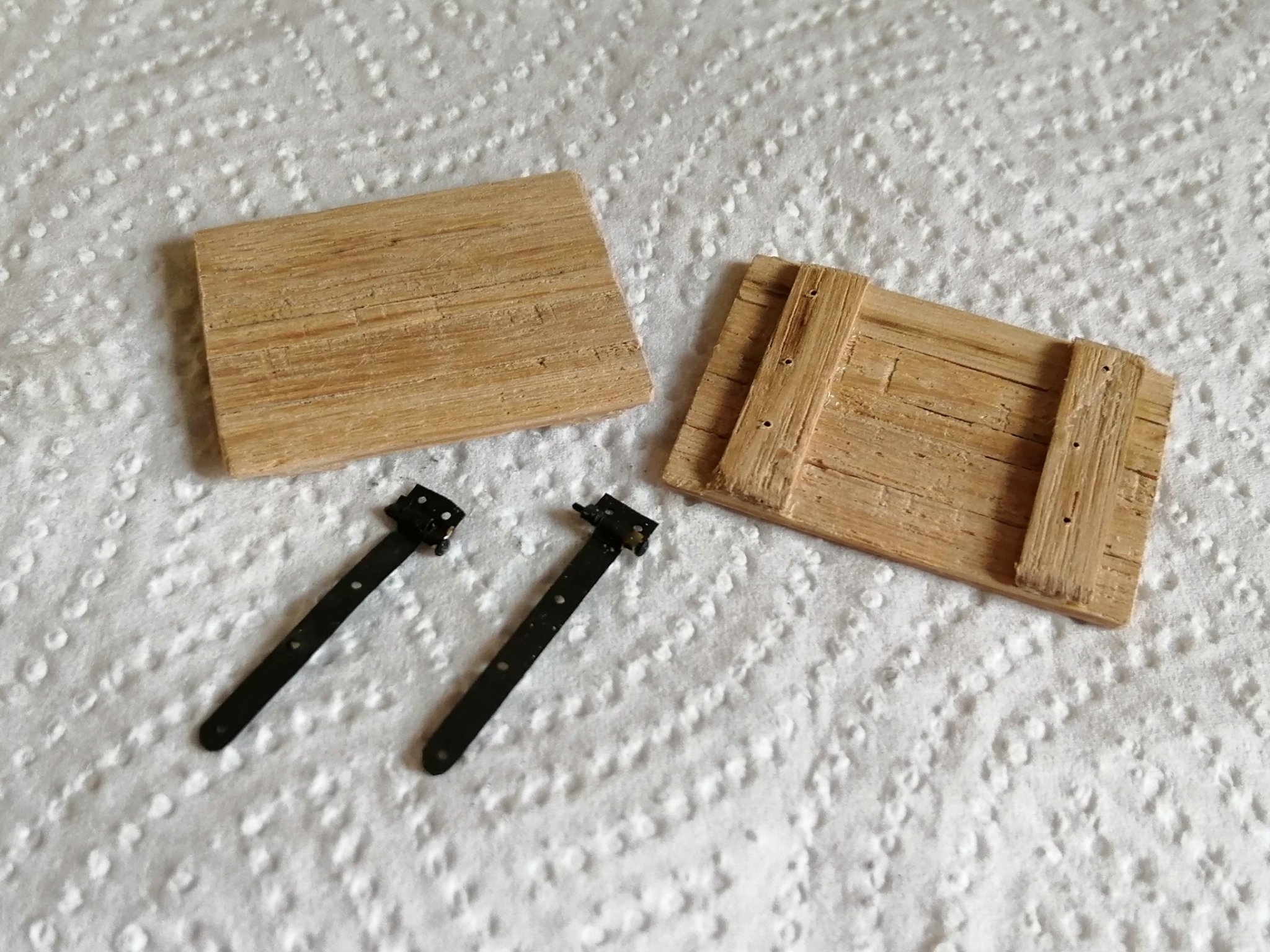
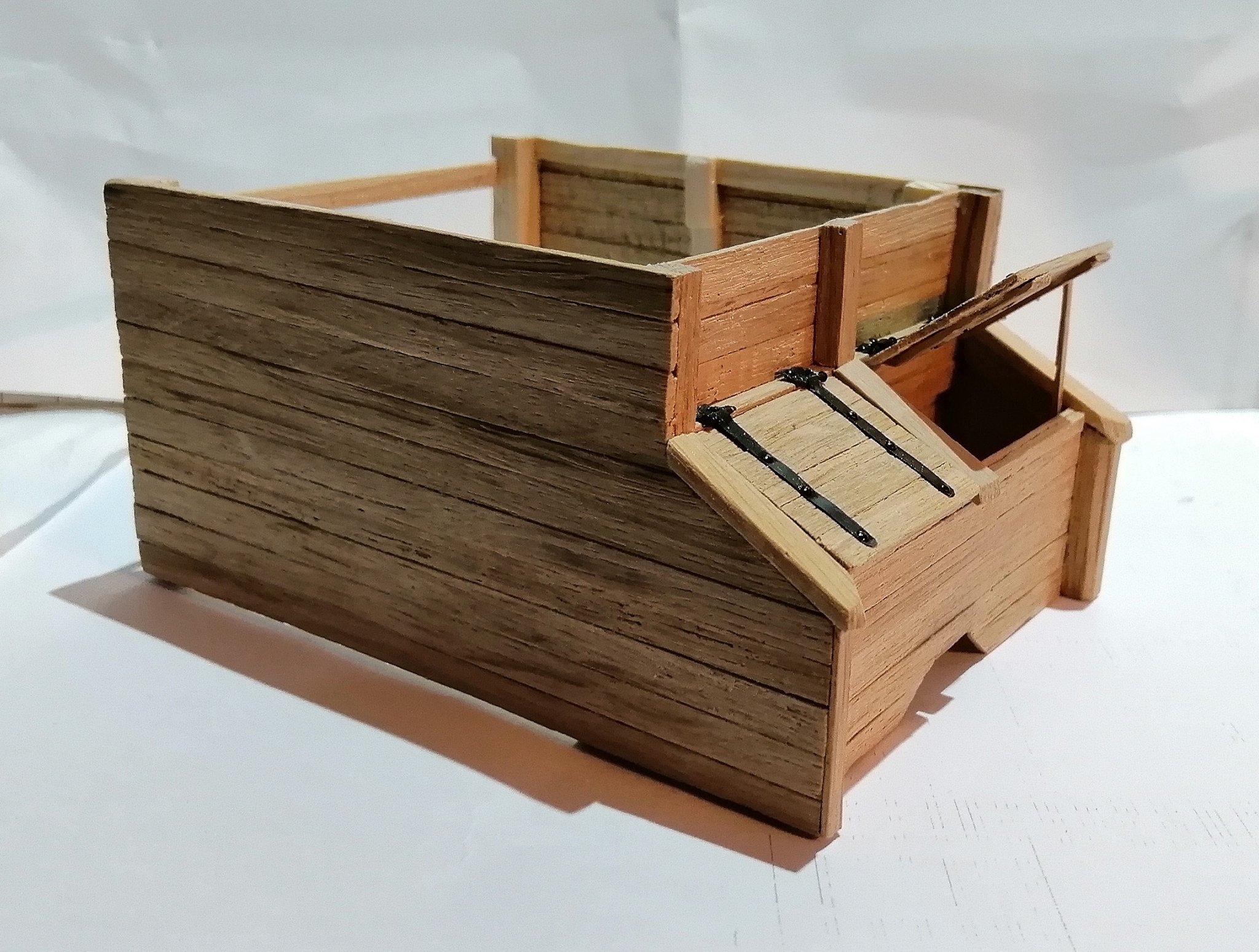
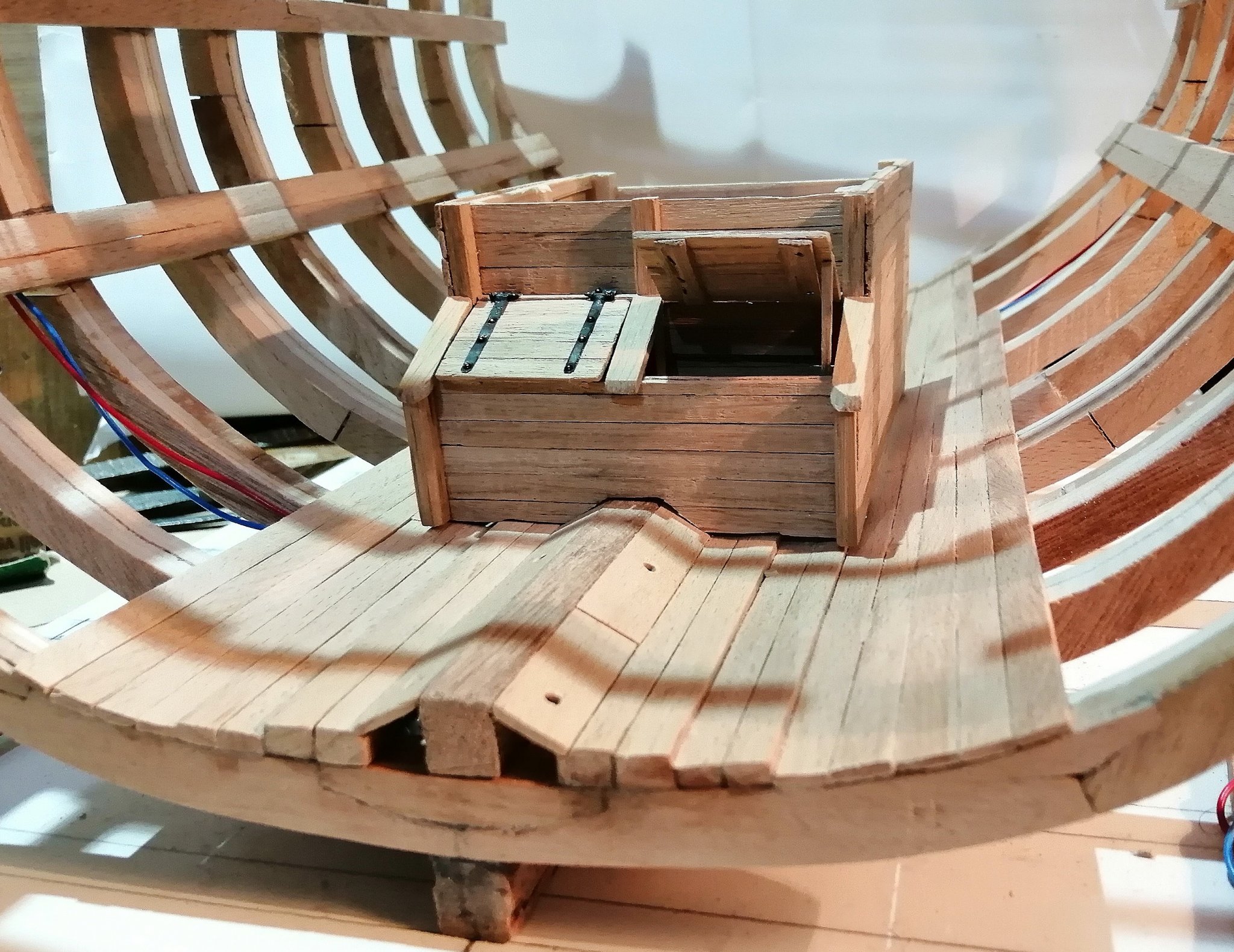
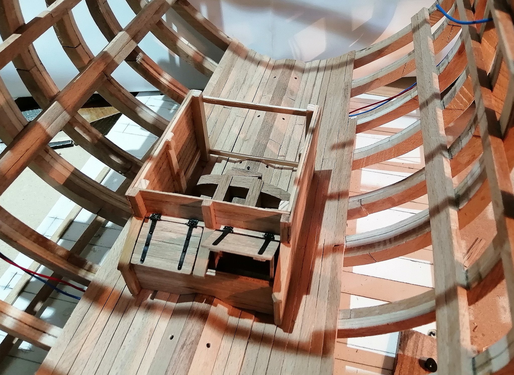
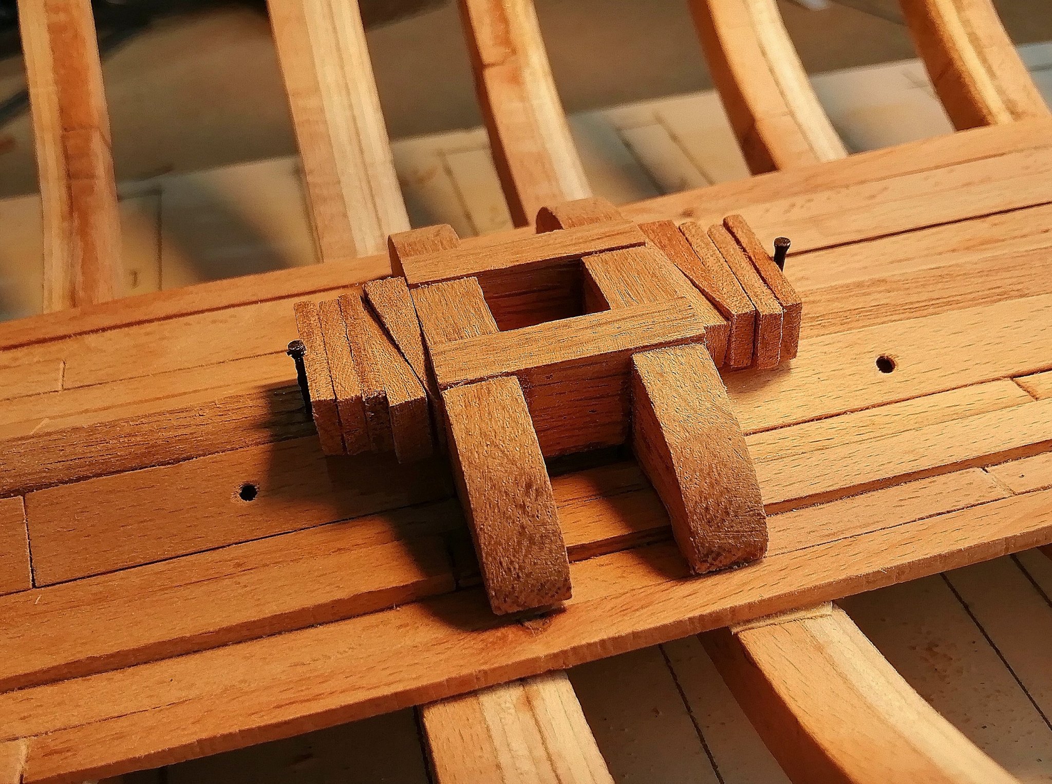
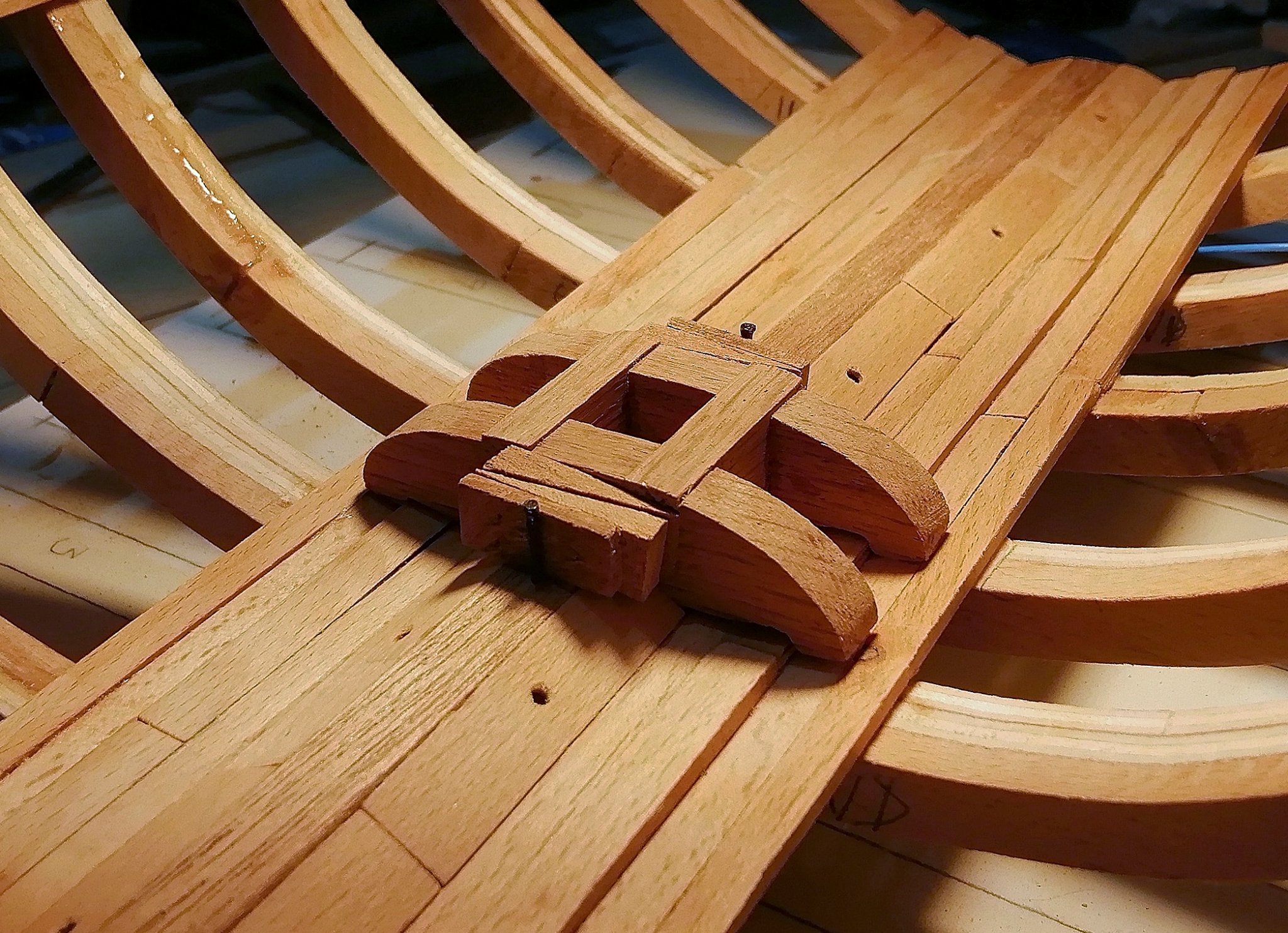
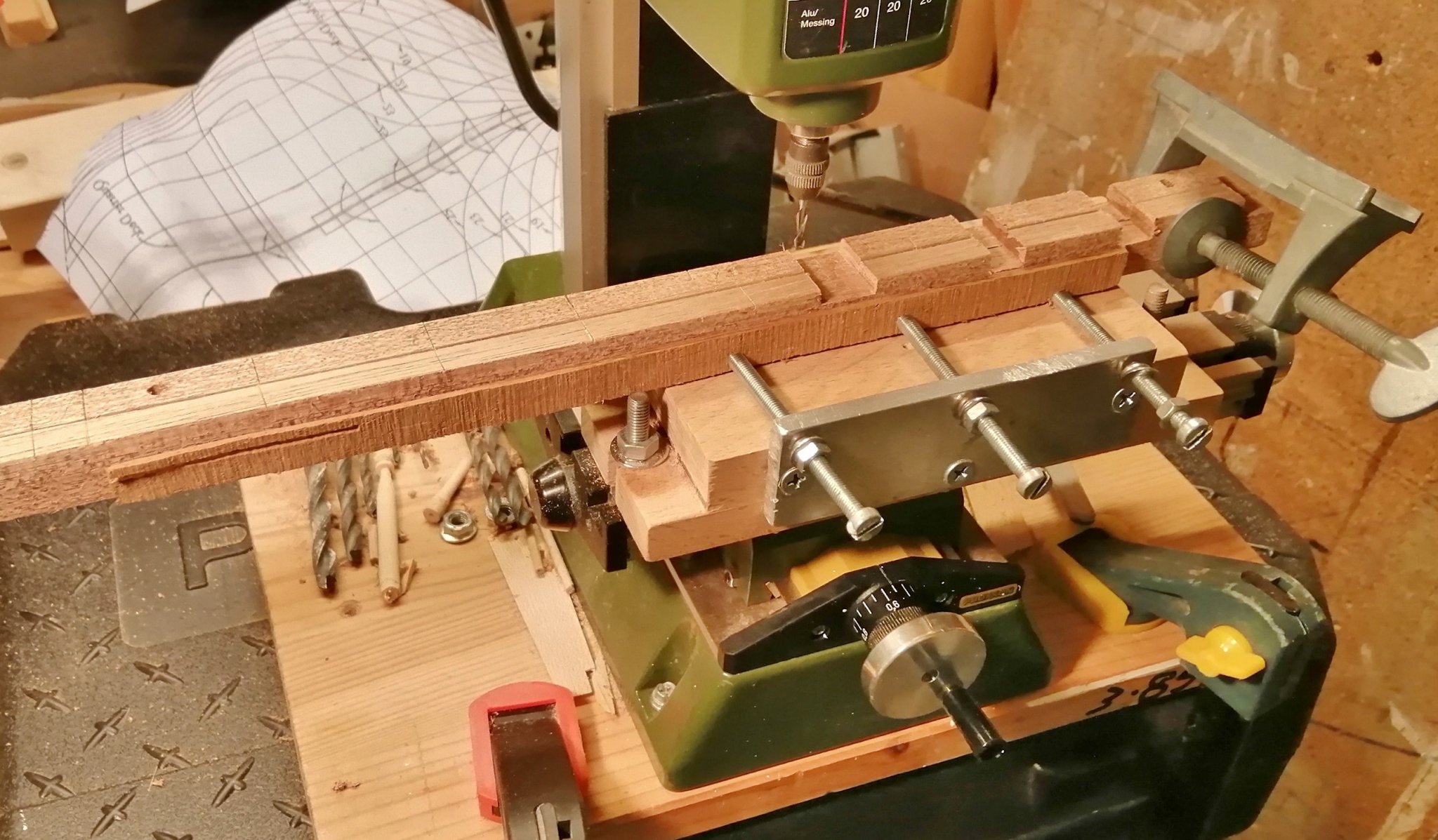
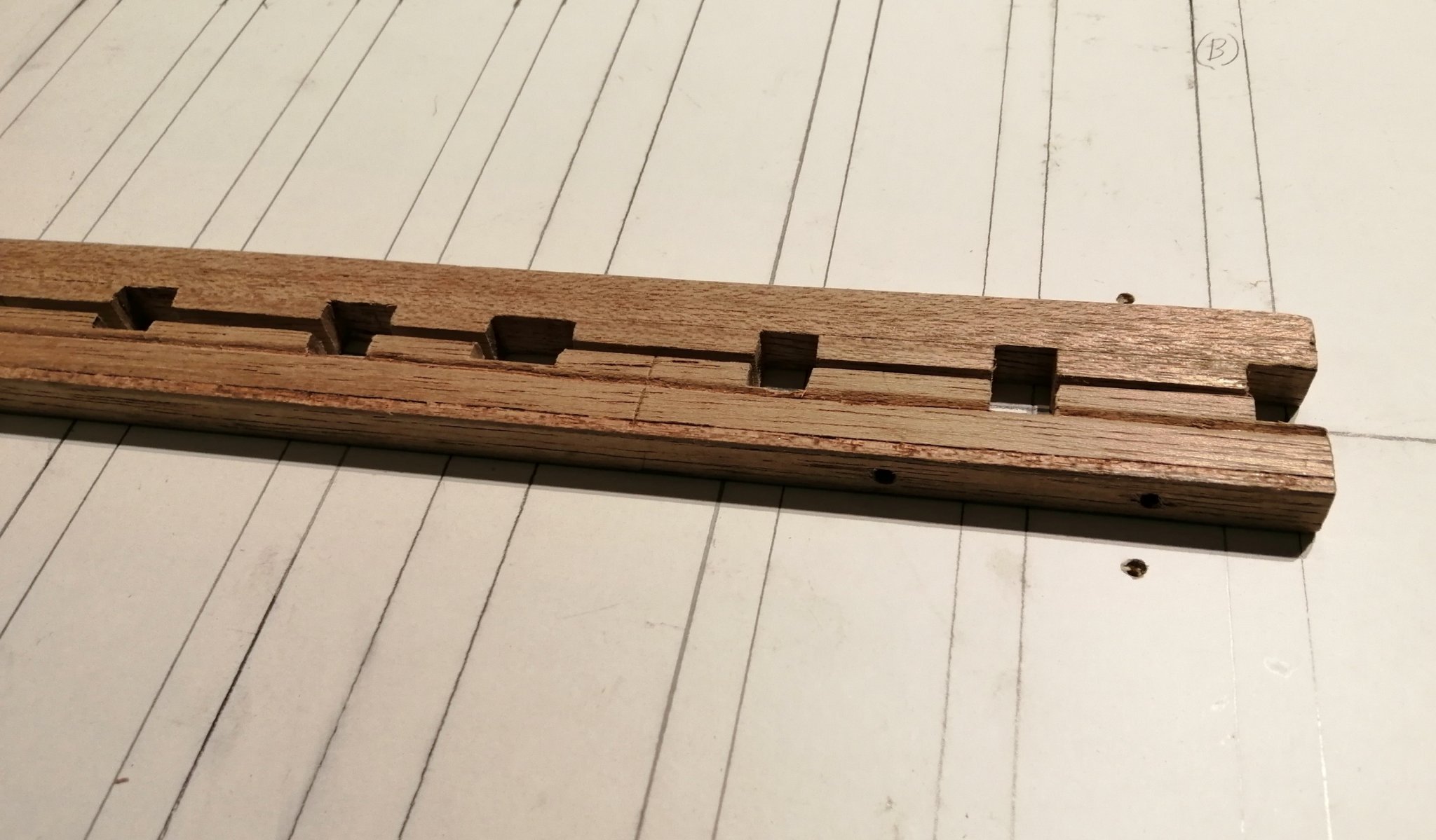
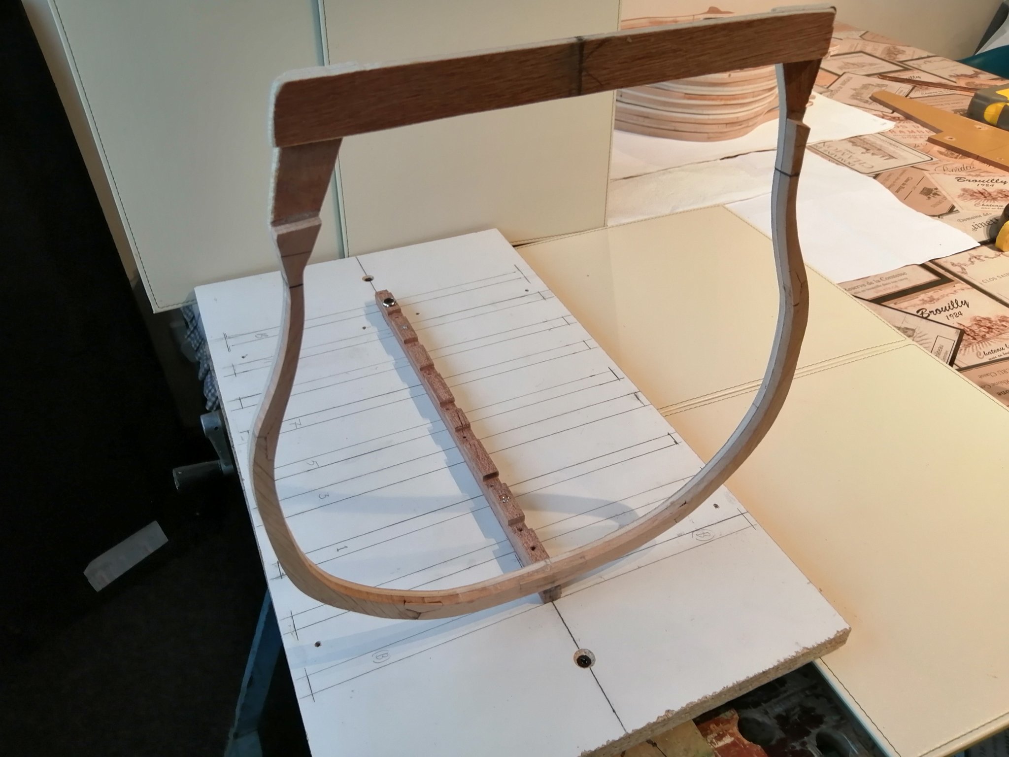
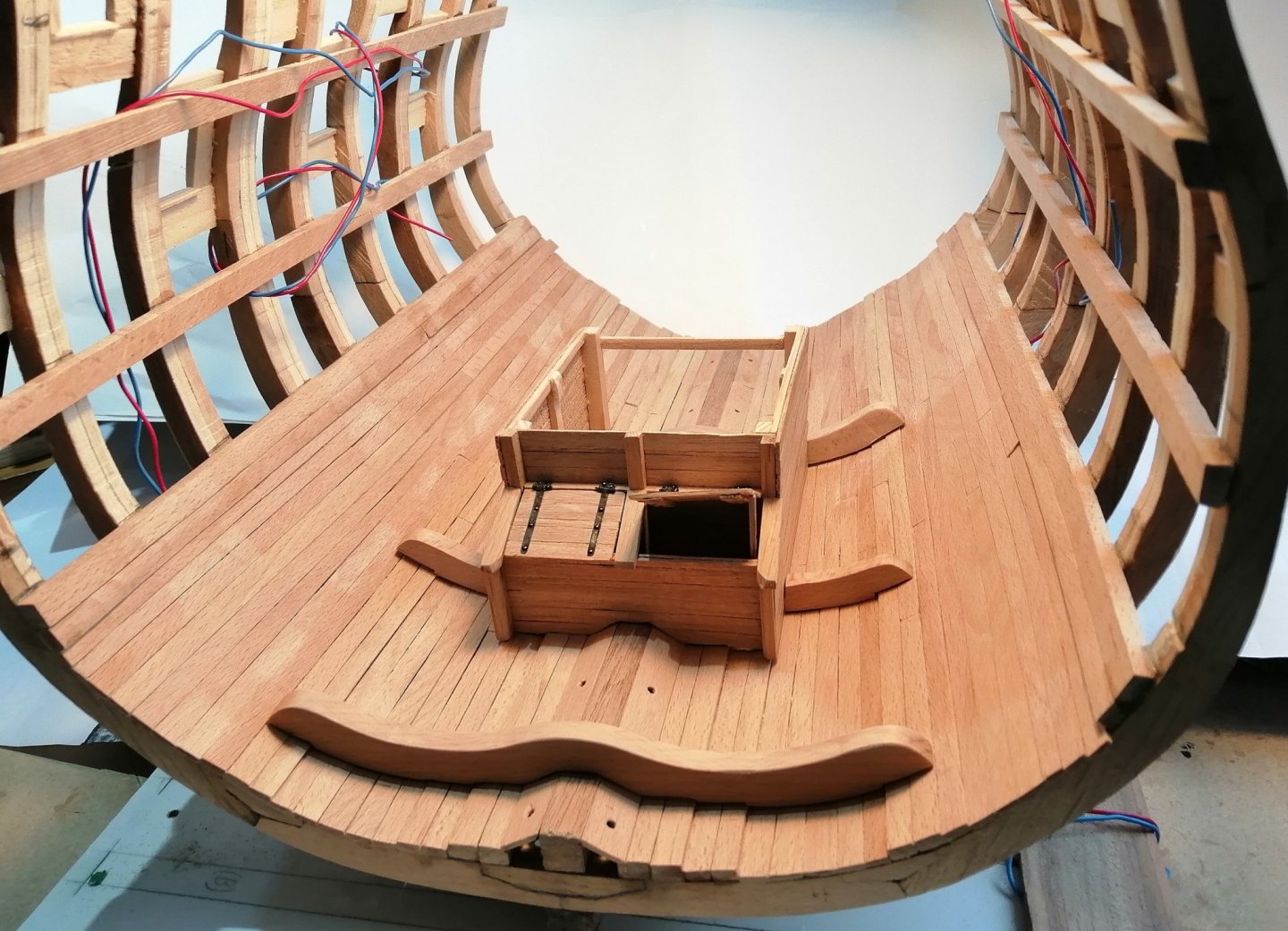
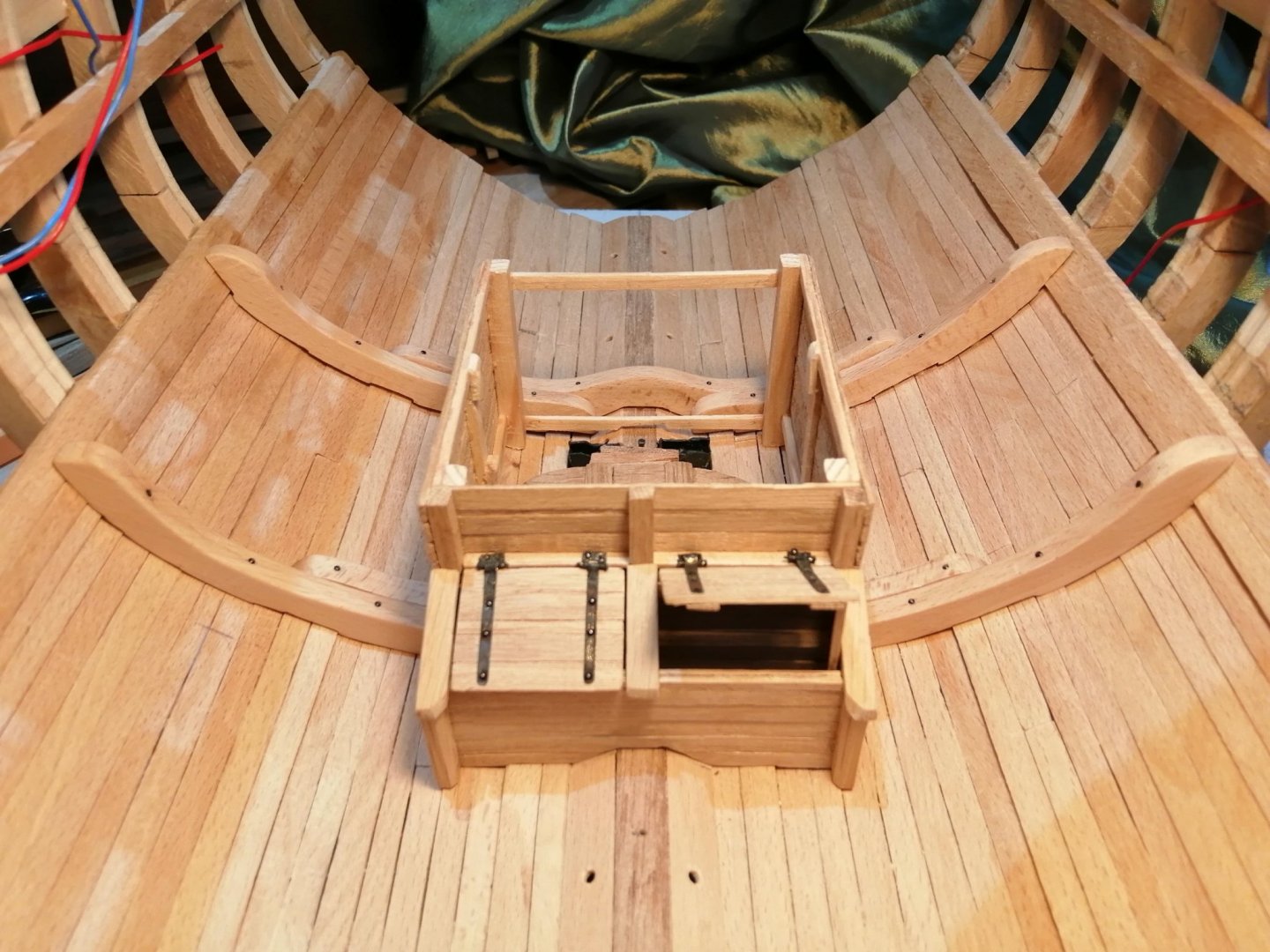
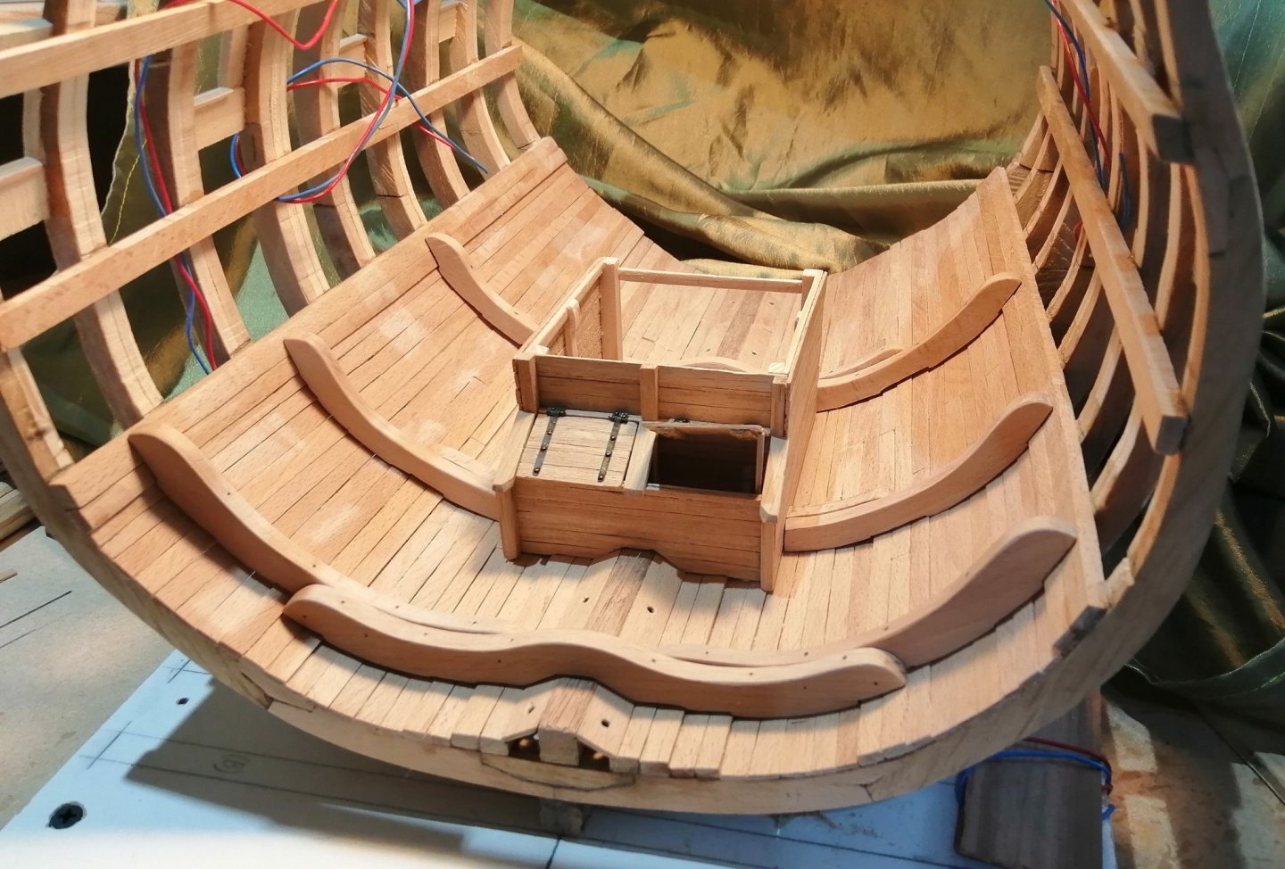
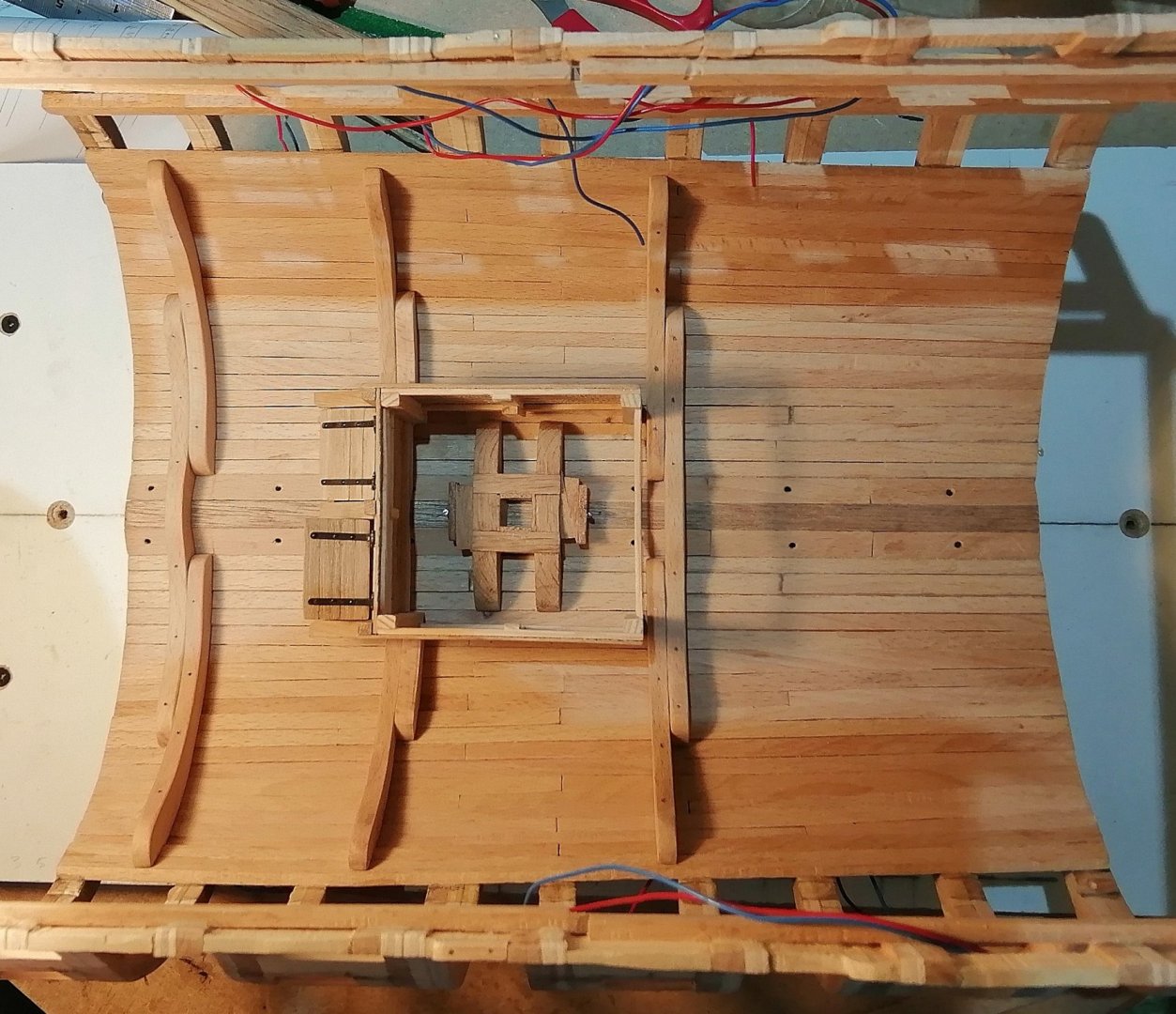
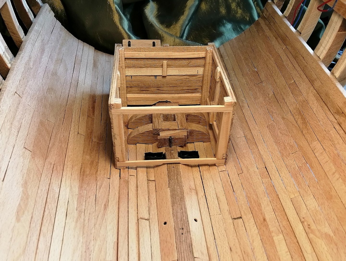
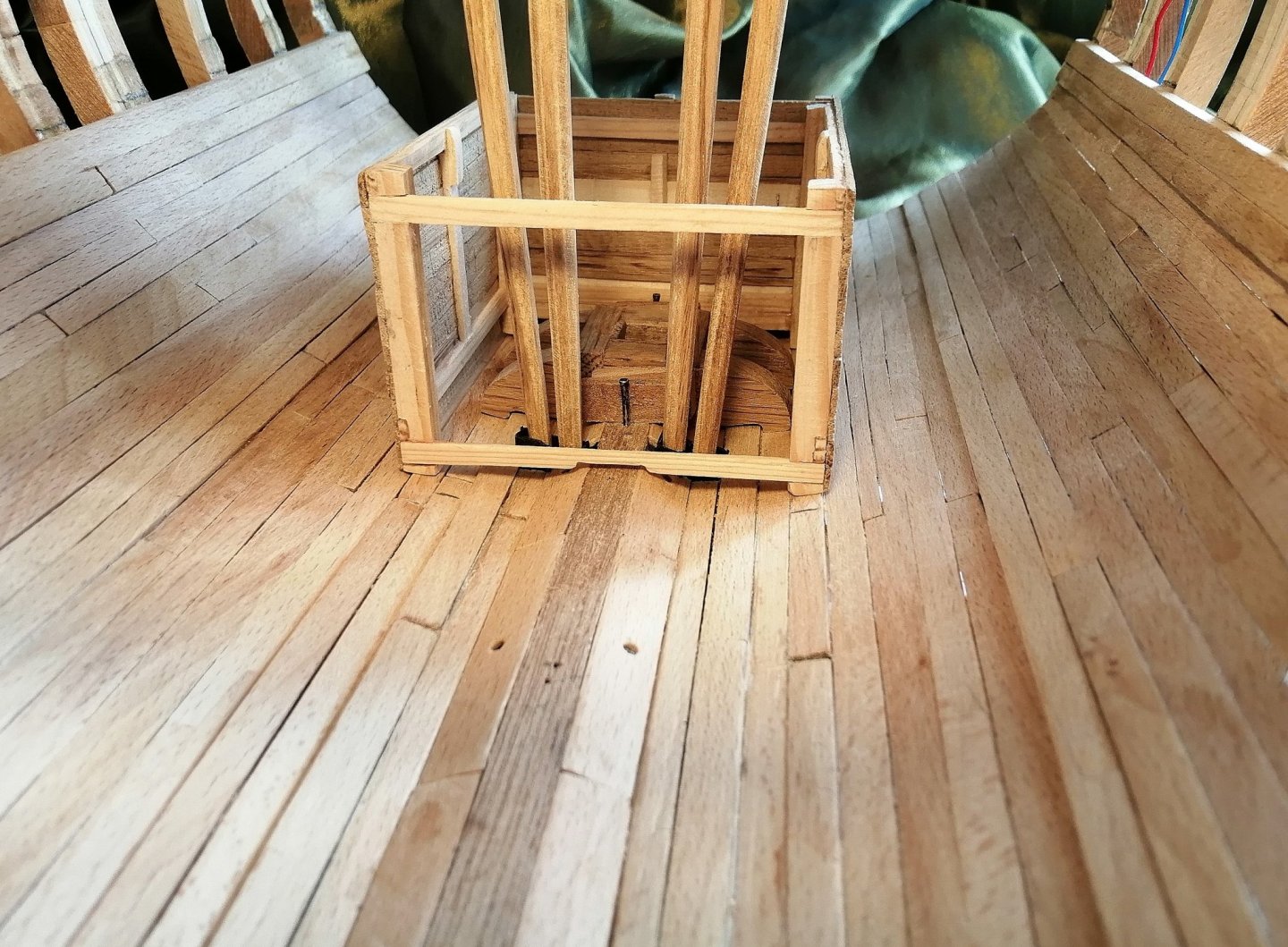
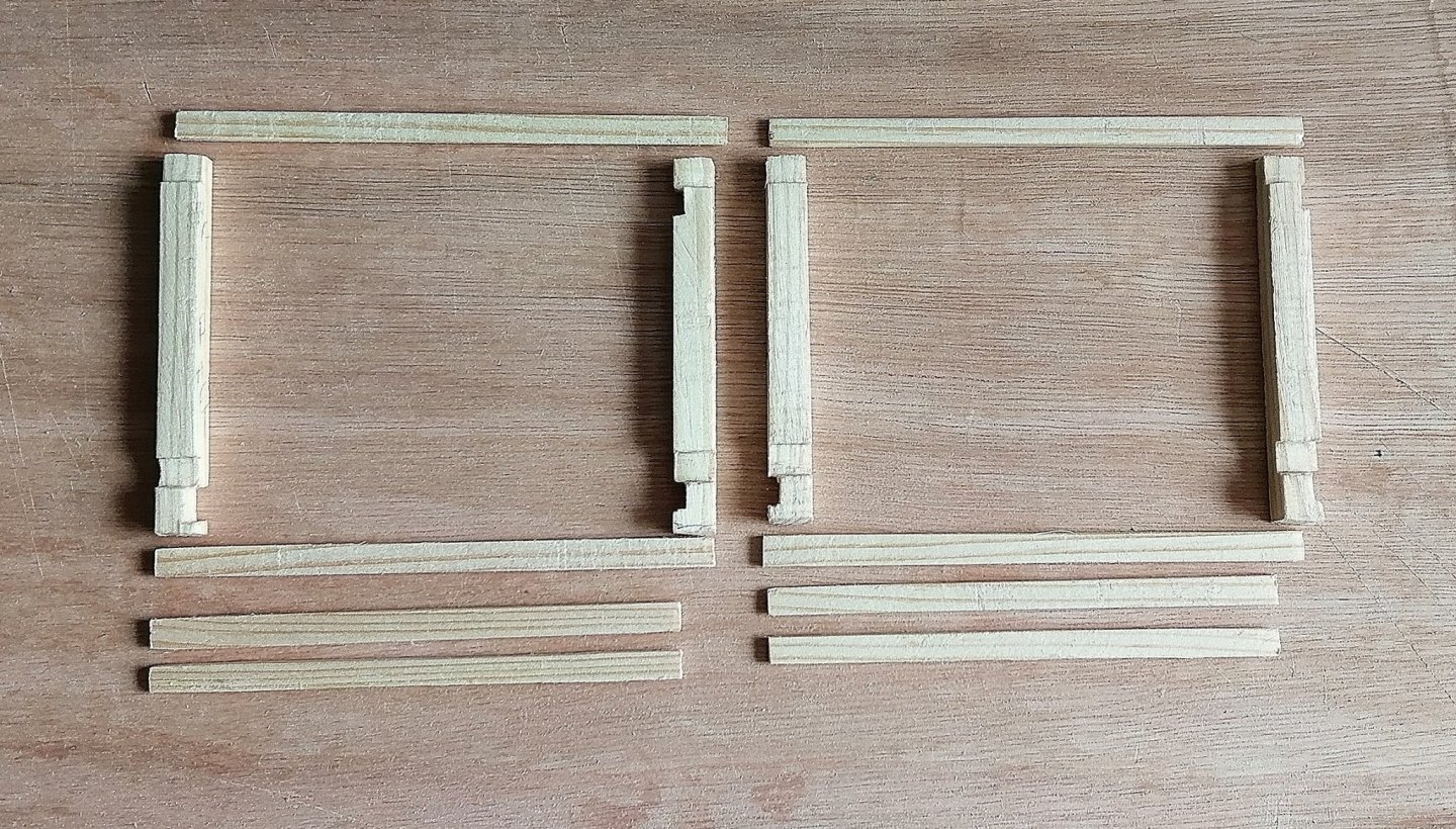
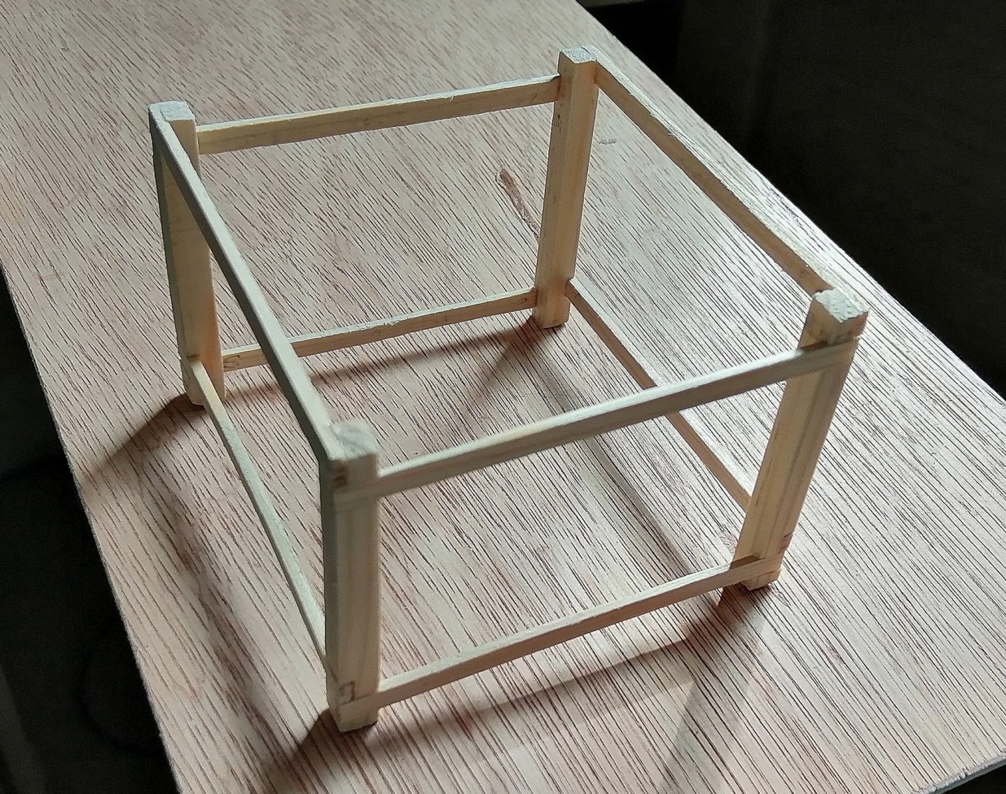
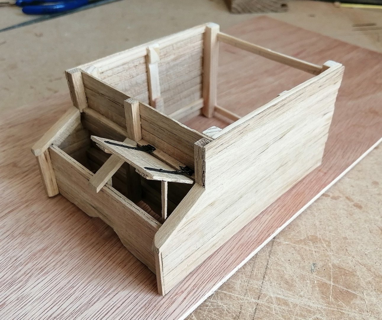
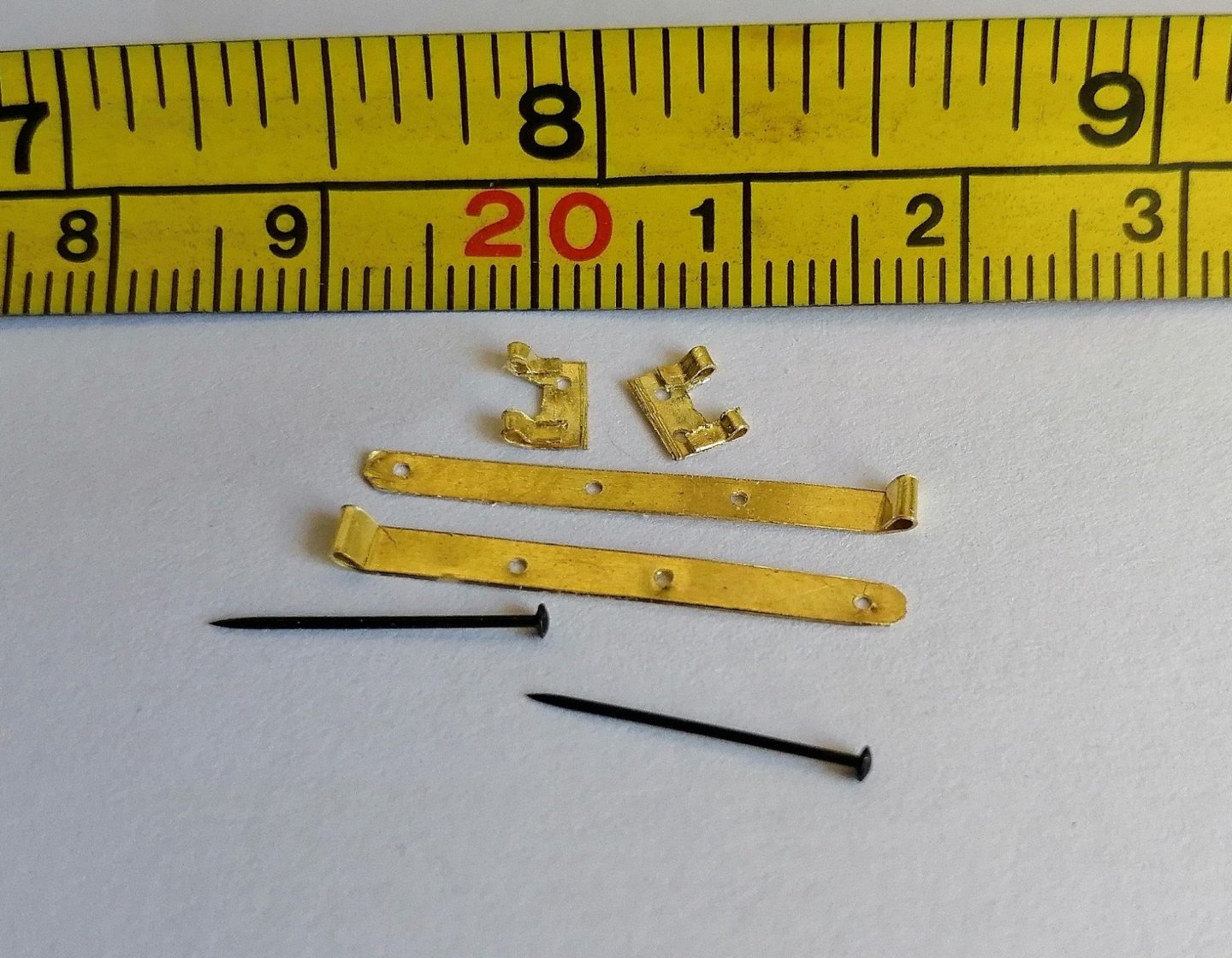
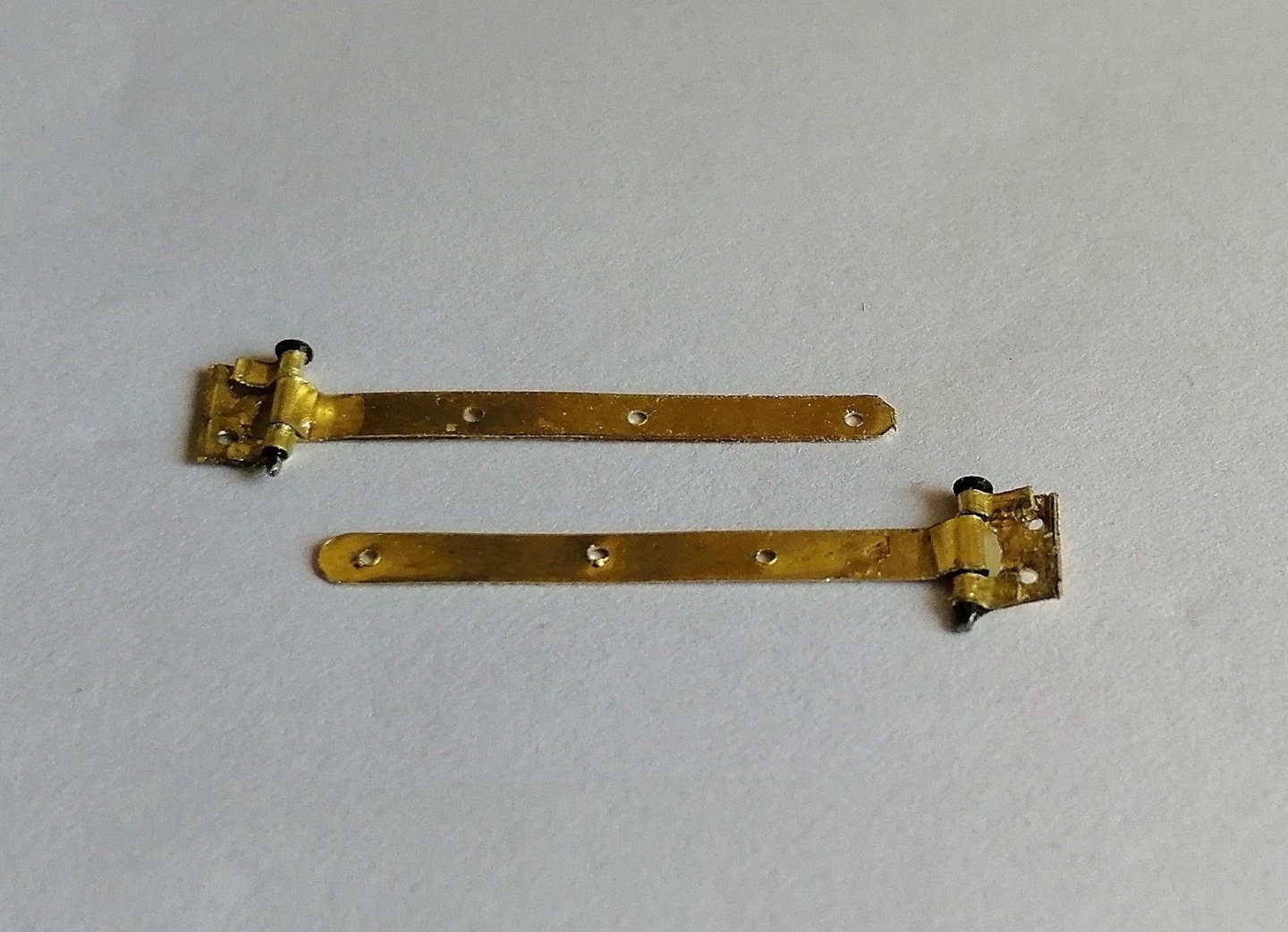
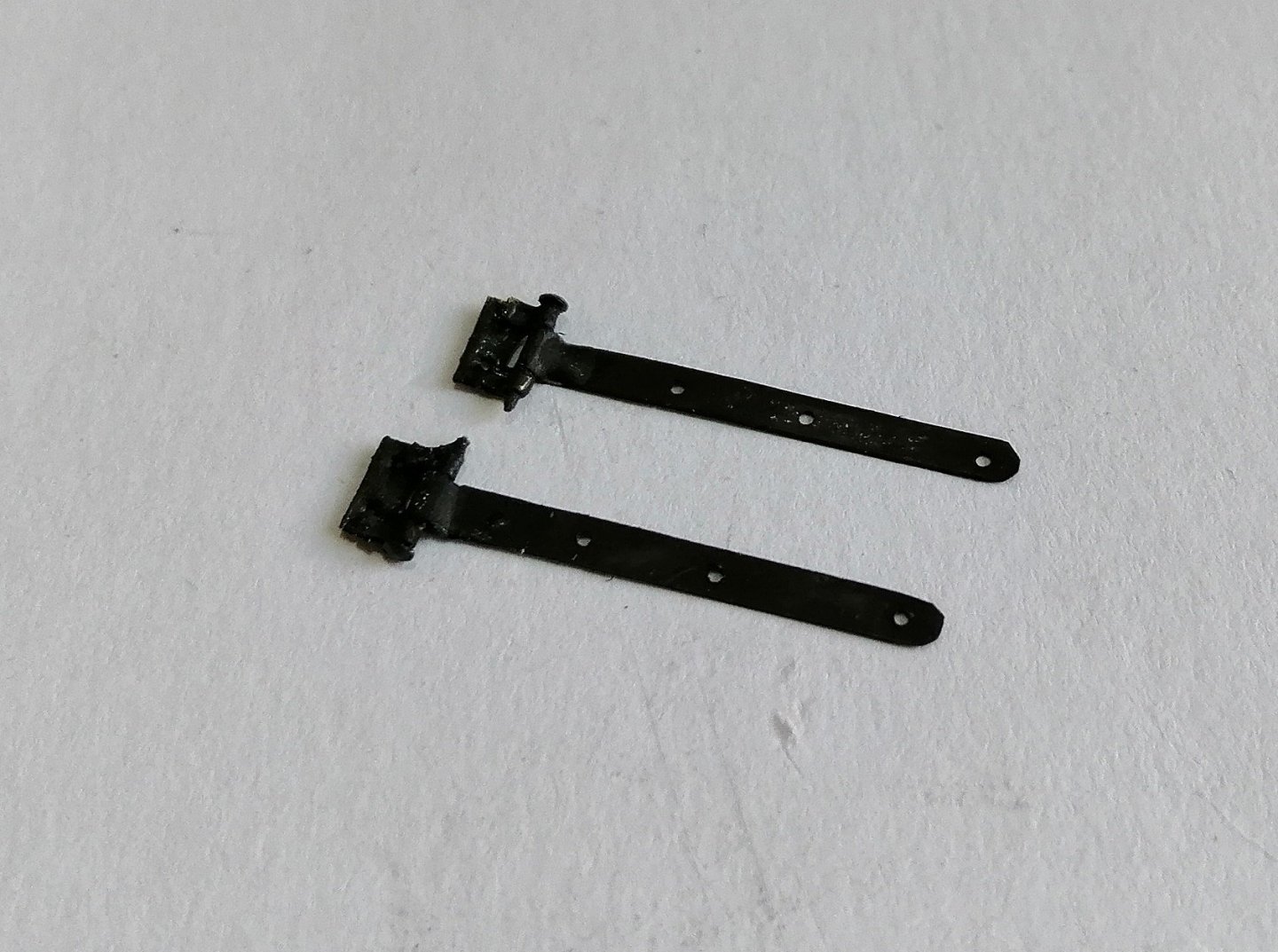
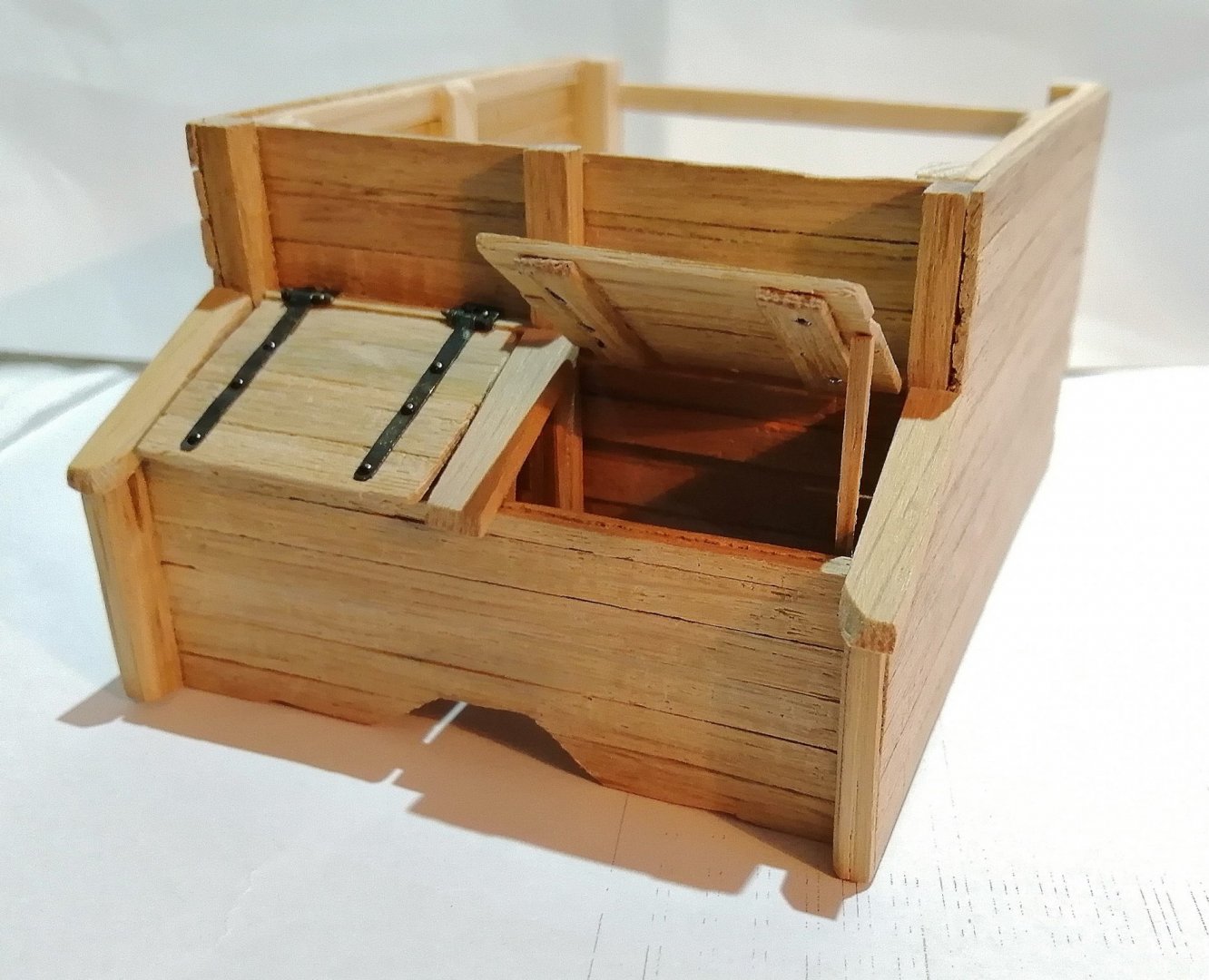
Basic parts of the frame for the lower well > For these parts I used softwood as my supply of beech is running low and right now with the Covid 19 lockdown there are no timber suppliers open and who knows when things will be anywhere near 'normal' again. I have a little more oak than I have of beech so for the planking of the lower well I used oak. I opted to have one of the shot locker lids propped open > My first attempt at working hinges. Apart from the rudder hinges on my other build, all the other hinges (gun ports) were just dummy, static hinges. And blackened > With both lids > I've chosen to leave the aft end of the well un-planked for two reasons -- 1) When finished, the model will probably be displayed with the aft end facing a wall so the open backed well will not be seen, But - - - 2) If it is displayed with a view in from the aft end, then all the business of the mast foot and step as well as the pump tubes will be visible. A 'test drive' in its position in the hold > Then, it's back in a 'safe box' until time to be permanently fitted.


-
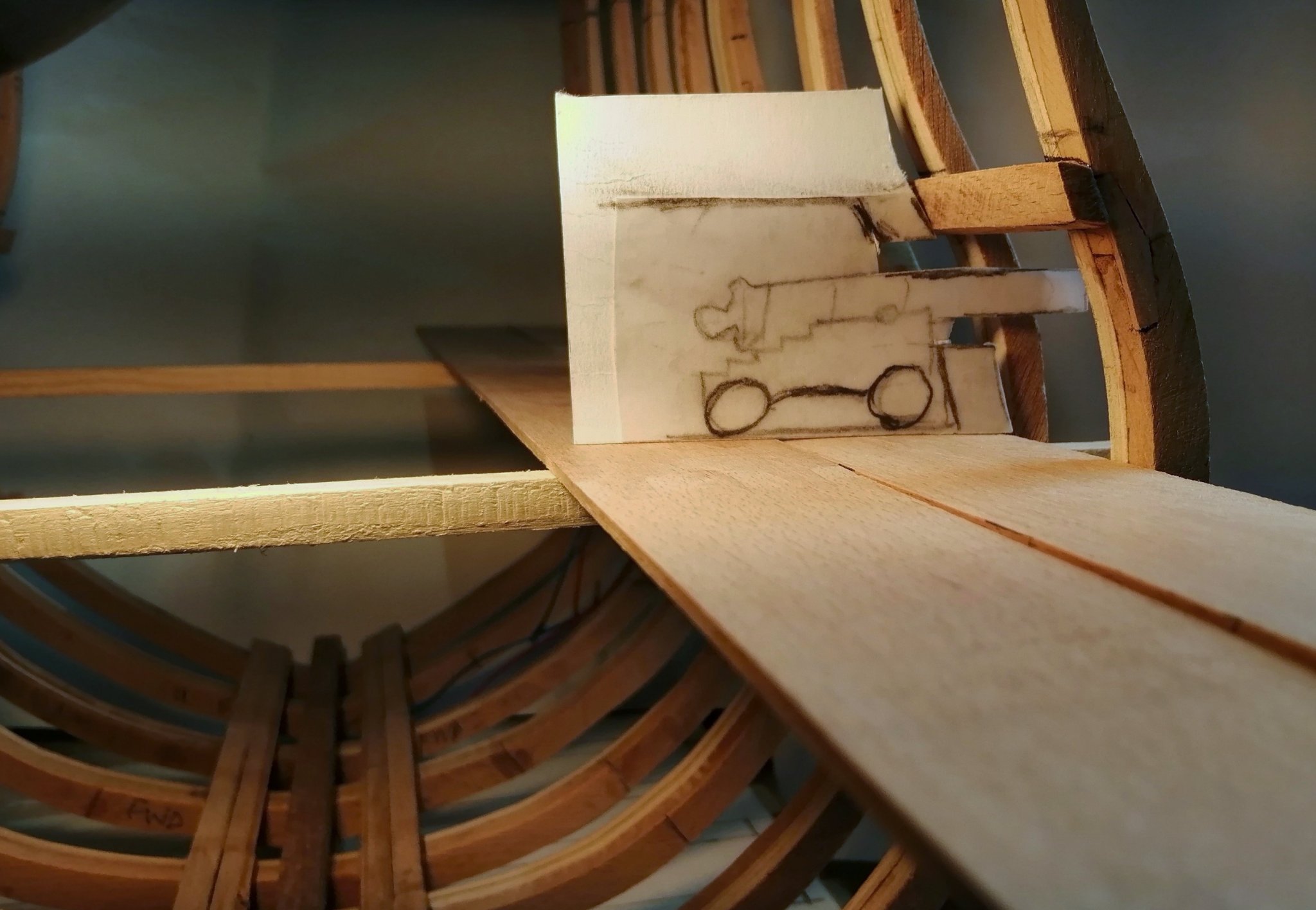
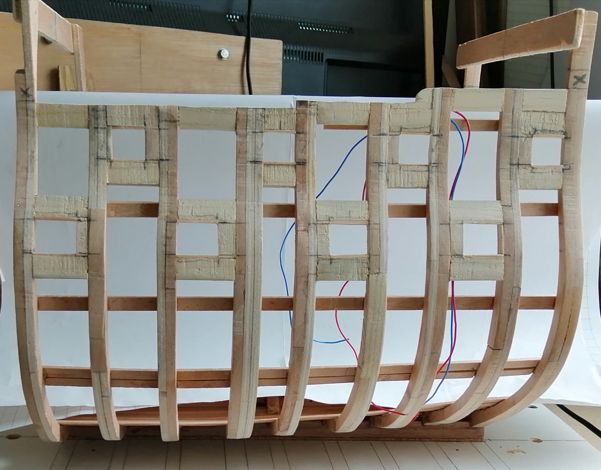
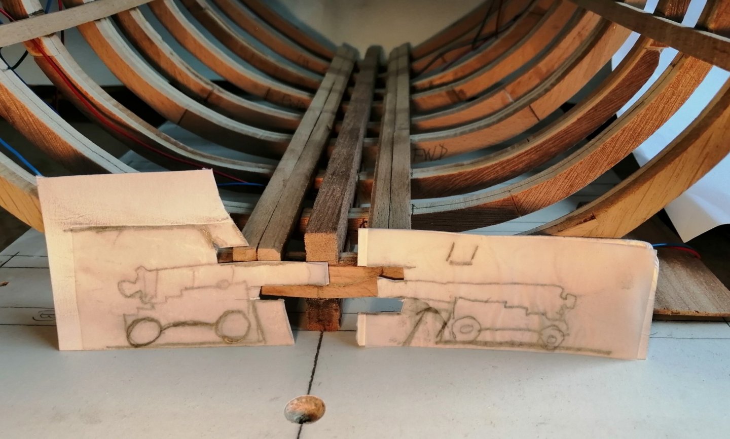
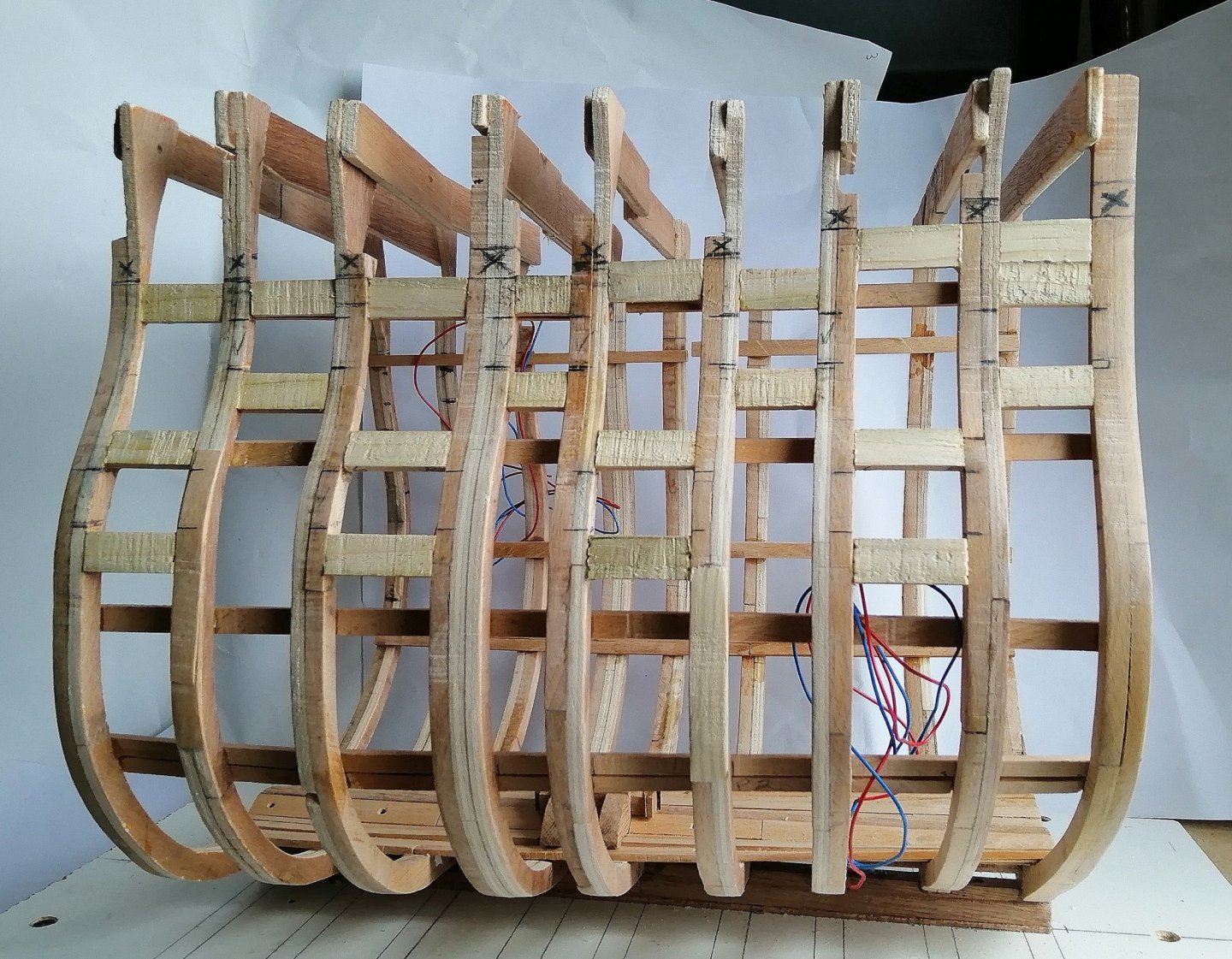
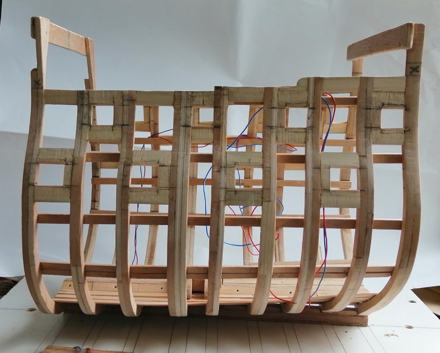
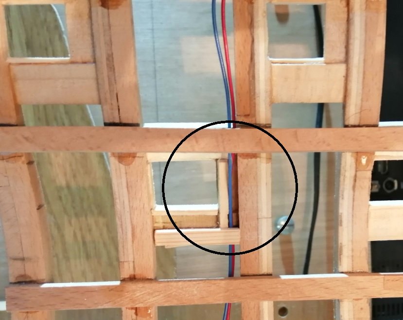
Upper gun and quarterdeck clamps fitted then took some time to glue in fillers along the frame tops as well as in the areas of the gunports. All the "Xs" on the frames above, each with a line underneath, define the rough height of the frames. As I've never done this kind of build before a lot of thinking about the sequence of things has been going on. I know that before I go near the orlop a whole lot of stuff needs to be done in and around the hold although I did spend time establishing the exact positions of the gunports. (The picture above just shows their rough positions.) In my other build I established and framed all 48 gunports before any hull planking was commenced and that worked well for me, so I'm doing the same with this section. With the gun deck clamps in position I used dummy beams and deck planking to help with the gunport positioning. (I know the gun deck beams are cambered but for this exercise I just used flat 'beams'.) I used cut-outs of very badly drawn guns to mark the tops and bottoms of the gunports (I think that every post should have something to laugh at -- so here comes this one . . . ) > Yes ~ I know they look ridiculous but they served their purpose. (I hope I can make the ship's guns and carriages to look better than that!) > The side elevation of the body plan gave the fore and aft limits of the gunports. > Staying with the frame tops for now, with the exception of the foremost and the aftmost, I eventually cut off the excess parts to make it a bit easier to work inside the hull, and these athwartship pieces of plywood were also creating unwanted shadows. I left the two end frames uncut as they may prove useful at times when the section is upside down off the baseboard. The final gunport positions. . . . and a rarely seen feature on 18th century ships - - a channel for wiring beside a gunport > Some work also done on the footwaling, thick stuff and ceiling planking down in the hold >


-
Hi Tom, Just as Timmo said above -- remember it's your ship! Like you, when I built mine I kept everything fairly neutral. Apart from black, white and the natural colours of the wood the only other colours on the ship were in the bowsprit jack and the figurehead. Even at that, she had black hair, neutral-ish skin and a red dress. Your chosen colour is green --- just go with what pleases you.
-
Hi Tom, Pity about the tide. You should have done the sand castles in the Mediterranean -- virtually no tide there! As for doing more Leopard stuff -- since I had the basic plans/drawings I decided just to try to adapt from them. As they're not very detailed plans, that adds an extra bit of challenge! (as if just building a ship or section isn't enough of a challenge!)
-
Hi Tom, Your progress is looking great - - - at your present rate you'll soon be on to your next build! I can see a yellowish ghost-like shape occupying the figurehead's space -- I'm waiting to see it take shape! . . . and I can still see that scary looking bundle of 'stuff' hanging from the fore top. The main top's 'stuff' doesn't look just as scary! Your ship's boats are looking really good sitting there. I did make a start on my boats but got a bit stalled along the way. Meanwhile I'm having a go at a cross section (of Leopard) at almost twice the scale that I did the whole ship. It's really nice to be working at this scale for a change. B.T.W. do you have any pics of your sand castles that you could post? Stay safe in this very unsafe time.
-
Thanks again Thomas for your valuable post and to Jason for your comment. When I first read about the elm tree pumps exiting through the hull my mental image was very similar to the drawing in fig. 5/14 in your post Thomas. Very intriguing variations for the same end result. Jason, you're right about risk! Even just going to sea is a risk! I expect that these structures were fairly robust and for the most part, watertight . . . but any failure and - - oh dear! Even modern yachts normally have a selection of different sized bungs on board for whacking into the hull in the case of a sea cock failure.
-
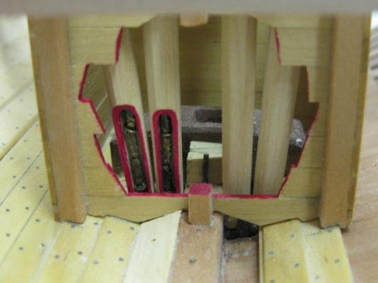
Thanks Thomas for that contribution! I have to say "Wow, this gets more intriguing!" While I'm now clear as to the routes of the main tubes and the inlet pipes and how the flapper valve system lifts the water, this mind of mine still has some questions! # In the link that Druxey posted the inlet pipe to port is open ended at its inboard end and obviously floods water into the bilges and I presume that would have been done to flush the stale, stinky water and gunge that accumulated there? (That water would then be pumped up by means of the chain pumps?) # If the bottom ends of the elm tree tubes were open into the limber channels then I have to imagine that when the inlet valves were opened the sea would (as water does) find its own level inside the ship which would have been at least half way up the orlop. This obviously didn't happen, so how was this prevented? (Was there a non-return flapper valve in the [elm] tubes below the point at which the inlet pipe joined it thus preventing the sea going down the tube? -- that appears to be the case in the starboard tube in Druxey's link, but the port tube appears to be open all the way down with no valve.) . . . and then there's the 'flooded cistern' system! # Looking at that, I have to assume that the cistern was fully water tight and didn't allow any water into the bilges? (I can't think of any other explanation.) # Do you have any further explanation or illustrations of the flooded cistern system that you could post here? Thank you. (and thanks to all who have suffered to read this far and endured all those questions!)
-
Thanks for that, Druxey. That's the best description that I've personally seen so far. That explains why the tubes go right down into the keel area and the inlets are much higher up the hull. I was a bit mystified by what seemed like 2 conflicting 'solutions'. A few questions if you don't mind. # Are these some kind of shut-off valves on the inlets just inside the hull? # At the bottom of each tube (at the keel/keelson) I assume the tubes are completely sealed off? # Why does the port inlet pipe differ from the starboard at its inboard end in that it appears not to mate with the tube? # Is that some sort of siphon system for drawing up the water? Thanks for any help coming to this thread.
-
After I posted the above I Googled 'the sinking of the Royal George 1782' and found this > "The Royal George returned to Britain for a major refit in 1780 and saw service with the Channel Fleet thereafter. By August 1782, with the siege still in progress, she was to join a new expedition to relieve Gibraltar as flagship of Admiral Richard Kempenfelt. She was moored off Spithead – the Royal Navy’s Portsmouth anchorage – and was taking on supplies on August 28th when, during deck washing, the ship’s carpenter discovered that the pipe used to draw clean seawater on board was defective. The inlet of this pipe, on the starboard side, was some three feet below the waterline and to access it would demand heeling the ship over to expose it. This was done by running out the guns on the ship’s port side as far as they could go and drawing in the starboard guns, securing them amidships. This action not only exposed the mouth of the pipe to starboard but brought the sills of the open gun-ports on the port side within inches of the water’s surface. Though the exact number could never be confirmed it was estimated that up to 1200 people were on board, including some 300 women and 60 children. I found the above on this website > https://dawlishchronicles.com/the-loss-of-hms-royal-george-1782/ There's more info on there for anyone wishing to read it. I'm sure there will be other sites carrying an account of this event.
-
Thanks Dave and Jason for your replies. Dave -- I'm glad I don't appear to be the only one who has read about these pumps exiting through the hull! . . . and it was in a different book in which I read it. It was "The Anatomy Of Nelson's Ships" but at present I'm having trouble trying to re-locate that statement. Oh -- and if you were to come back to Edinburgh now you would find the other half of the streets dug up for more tramlines! Jason -- It would appear that between what you found in TTFM and what Dave found in Lavery's book that there were different locations for the inlets for these pumps. I know it may sound a bit fatal for a boat or ship having 'holes' in the hull but modern sailing yachts have, on average for a small to medium sized yacht, about five 'holes' for inlets, waste disposal and an inlet for engine cooling water.
-
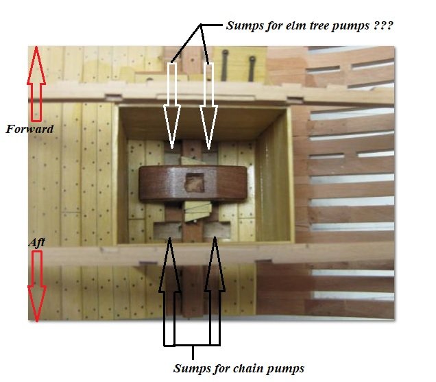
Thanks Capt Poison, Jason and Mark for your help. Captain Poison ~ in the last couple of weeks I've been through Dan's cross section log of vulture at least a couple of times and have pinched a few images from there that will be immensely helpful. Mark ~ thanks for that image. I've seen plenty images of the pump heads of the elm tree pumps in so many logs that I've viewed yet it seems to be a bit of a mystery as to what happens below that deck! Jason ~ I DO intend to include a couple of elm tree pumps up at the lower gun deck level and because of the upper well on orlop deck and lower well in the hold my section will continue to perpetuate the mystery of where the rest of these pumps go! In Dan's log there is this picture > There is also this picture > While this pic shows the four chain pump tubes, it's not clear what's happening on the far side (forward) of the mast step. I do have another puzzle in connection with the elm tree pumps : I have read (in a book, not on the internet) that the elm tree pumps exit the ship through the hull for the purpose of drawing sea water onto the deck for hosing and if necessary, fire-fighting. I have searched the internet, asking the question, but have not succeeded in finding any reference to that water drawing arrangement of the pump(s) ~ anyone have any information on this?
-
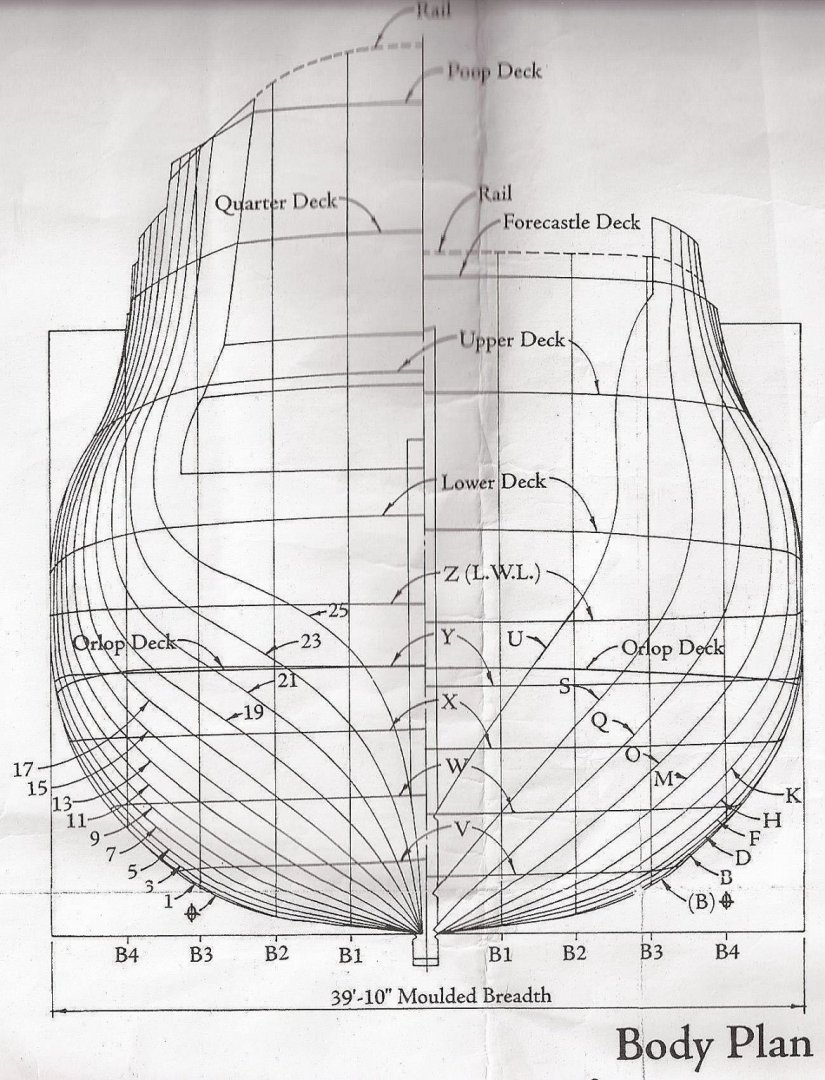
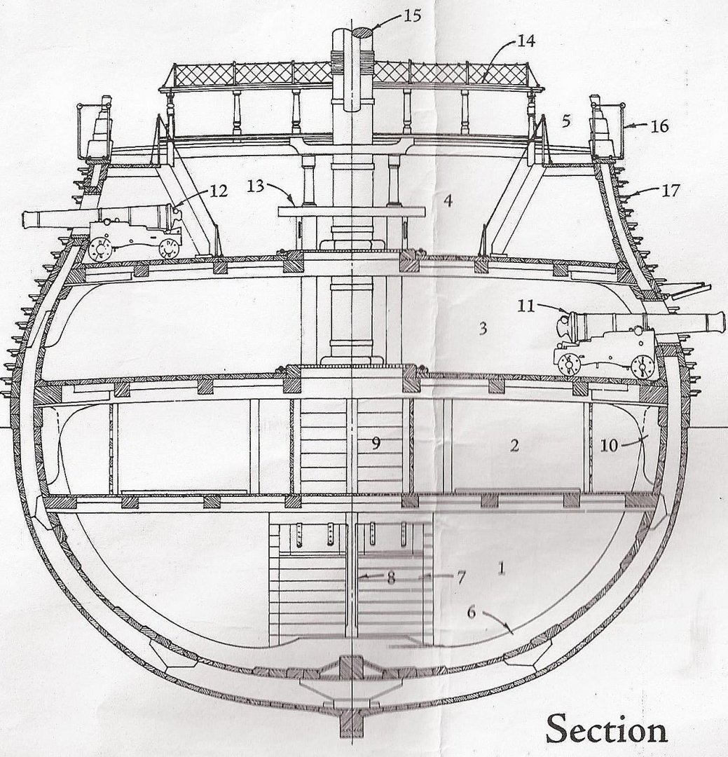
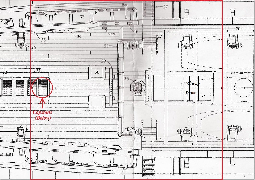
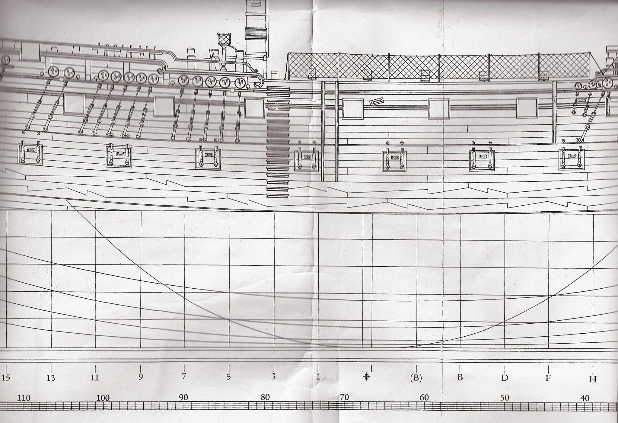
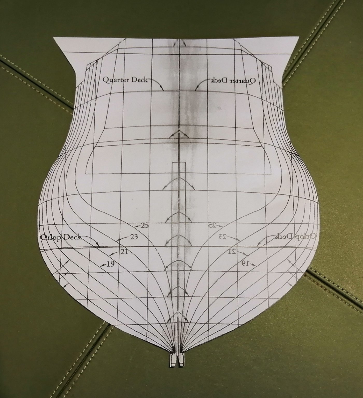
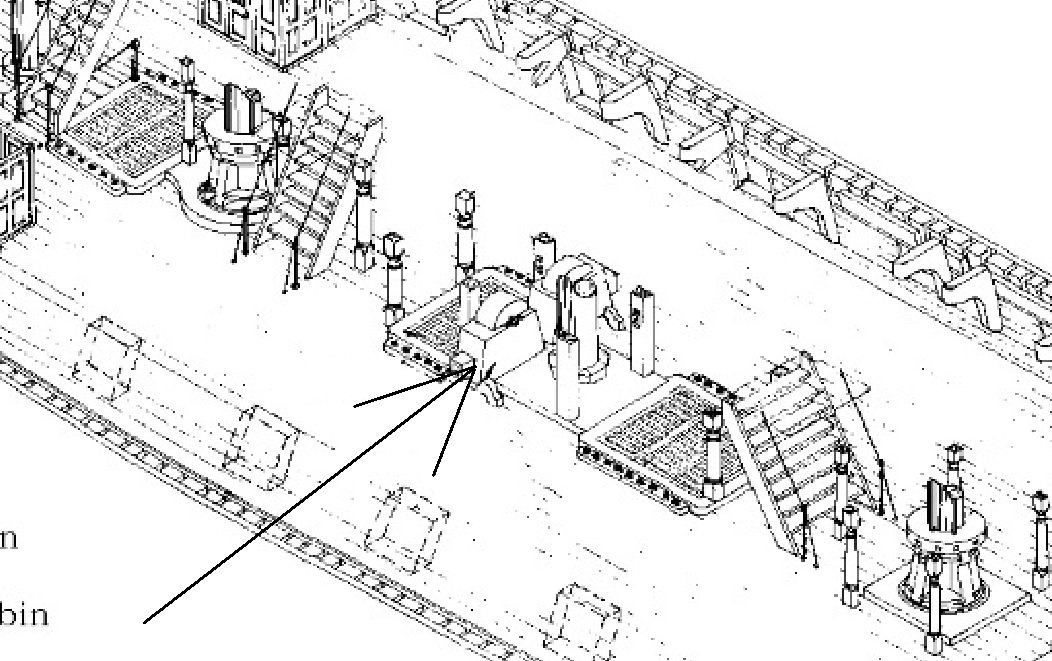
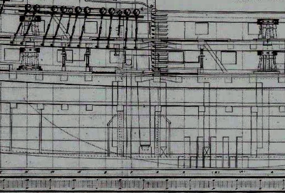
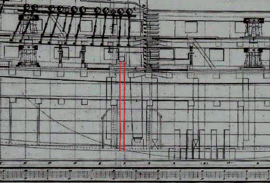
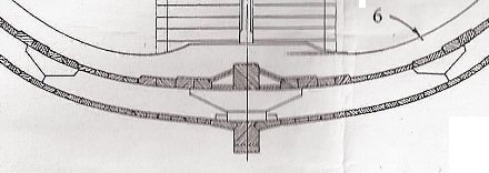
I'm in the early stages of trying to build a cross section and trying to get the hold area as complete as possible before moving upwards. The drawings, plans and any other information I have is fairly restricted so there are some aspects I'm 'winging'. The ship is HMS Leopard from1790, a 4th rate 50 gun ship. From the drawings I can see the location of the chain pumps but there is no sign of the elm tree pumps. Here's part of the lower gun deck drawing showing the chain pump cisterns - - - but no elm tree pumps > In the orlop drawing (below) are clearly shown TWO pump tubes behind the main mast, although I would have expected to have seen FOUR tubes instead of only TWO, and again, still no sign of any elm tree pumps. > There are no drawings or plans of the hold, and in the book "The Fifty Gun Ship", the best drawing I can find is this one > While the main mast step is clearly visible in that drawing, most other stuff in the hold is rather vague and I find it difficult to understand everything I see there. In the following copy of the same photo from above I've highlighted in red what appears to be the chain pump tubes but still can't clearly see any sign of the elm tree pump tubes > I'm now having to assume that the drawings in the book are not fully detailed but are only "roughly representative" of all the deck furniture and fittings? I'm also assuming that there MUST HAVE BEEN elm tree pumps on these 50 gun ships -- but where? On most other (English) ships of the era the heads of the elm tree pumps all seem to be located immediately ahead of, or adjacent to, the main mast, and the sumps located ahead of the mast step on both sides of the keelson. So, I'm looking for all you nice guys out there to help me! Thank you.
-
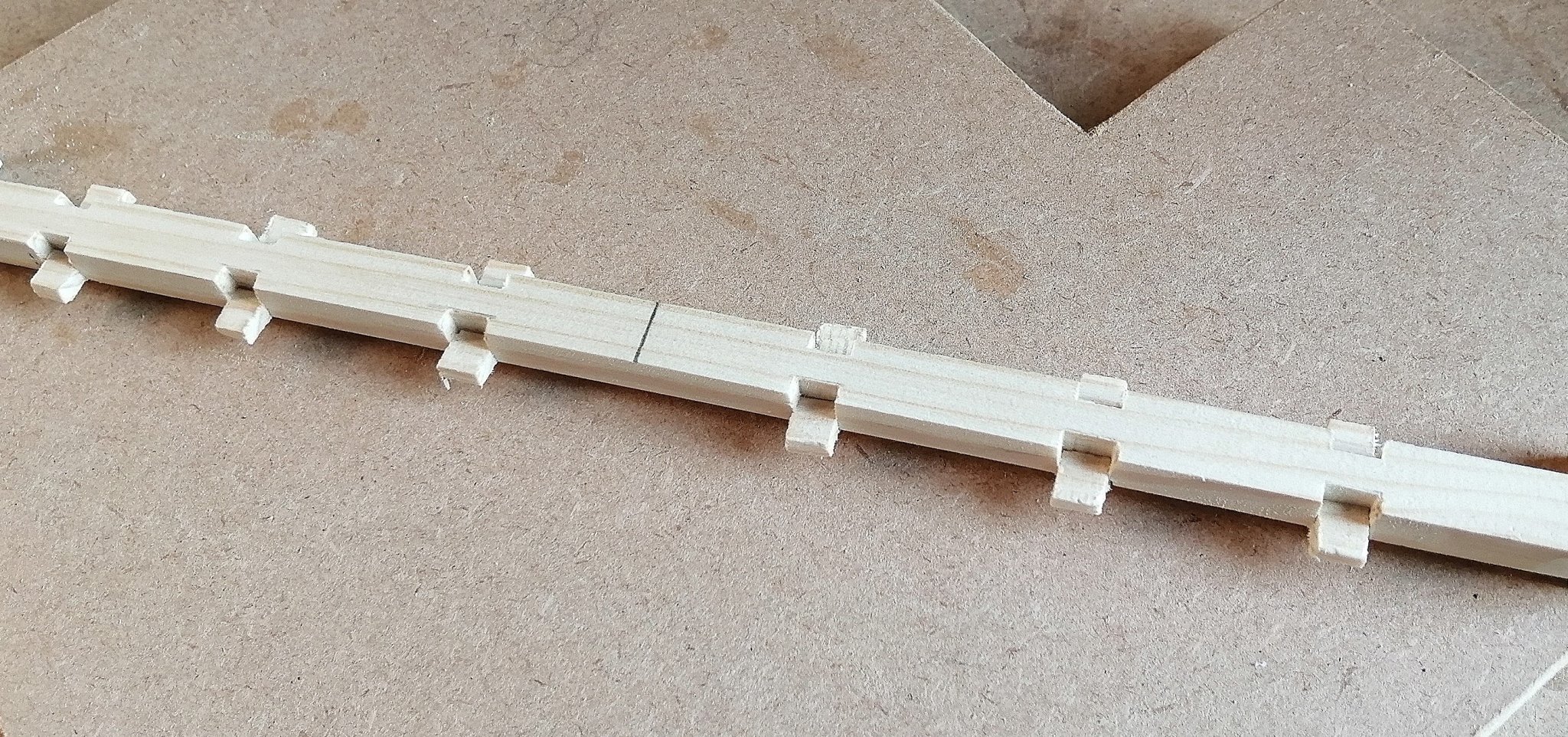
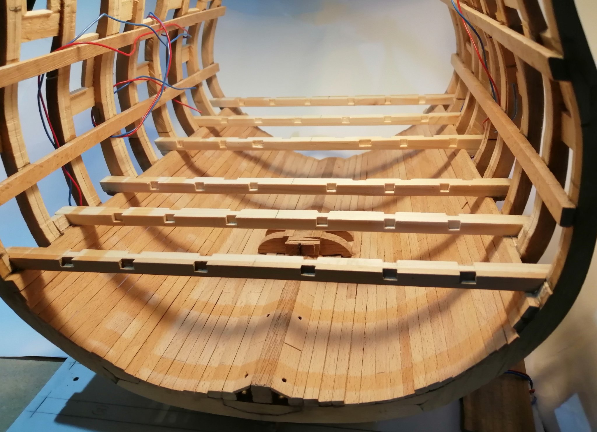
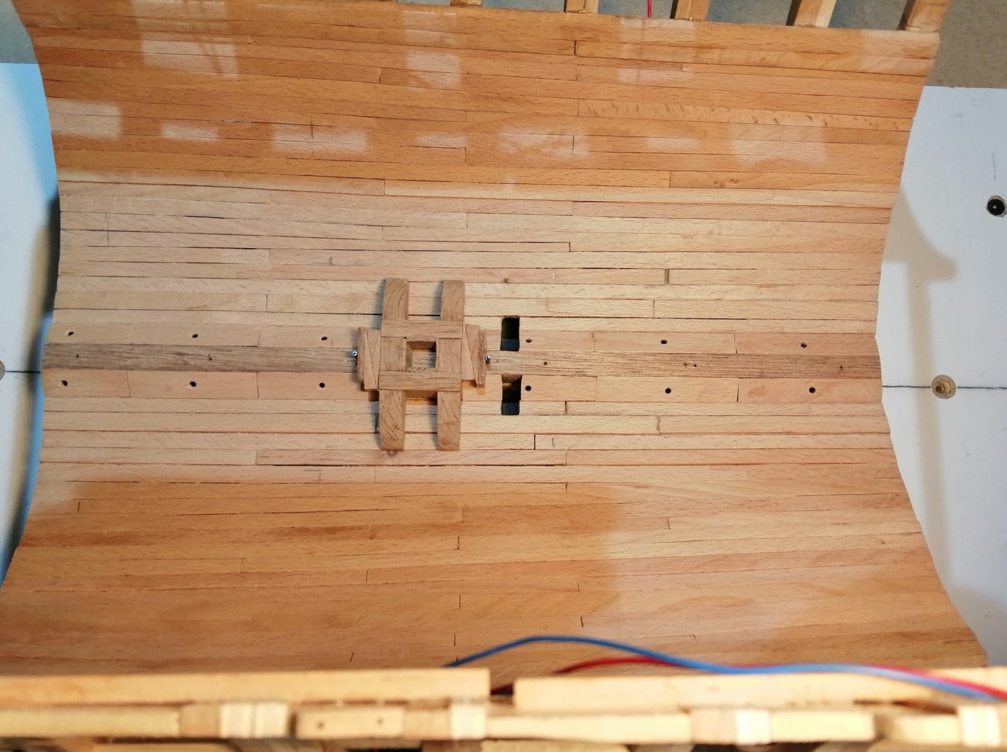
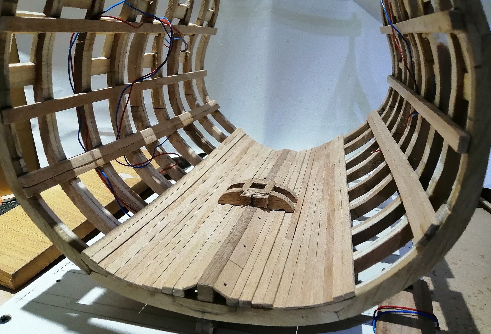
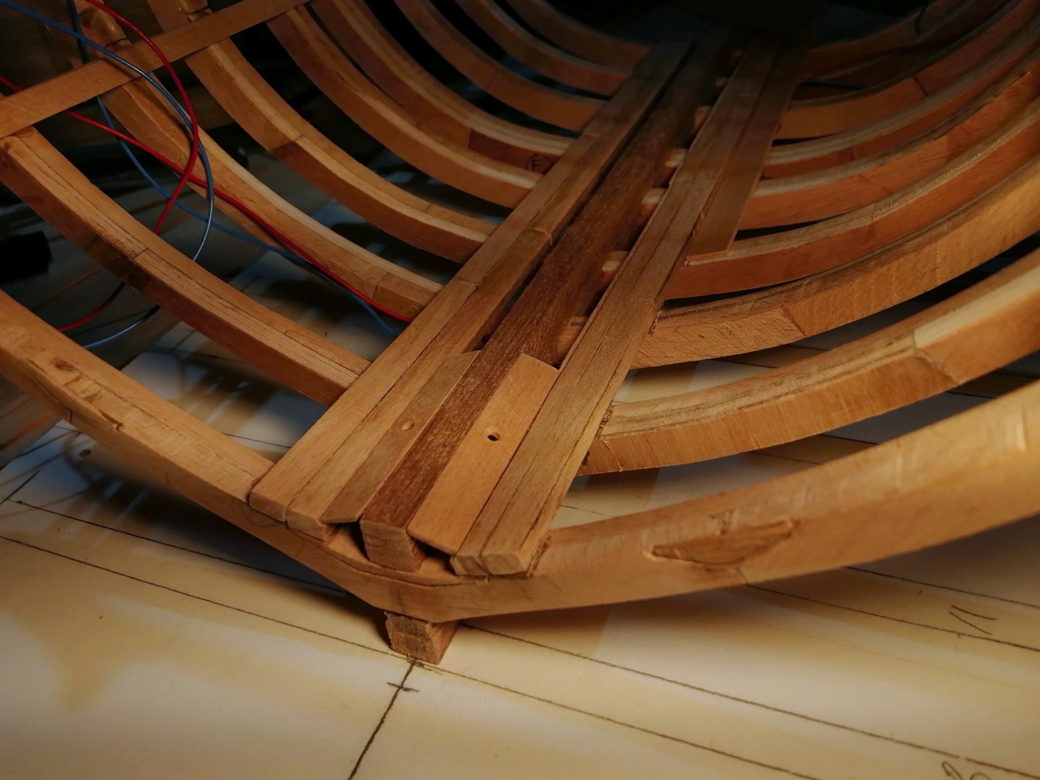
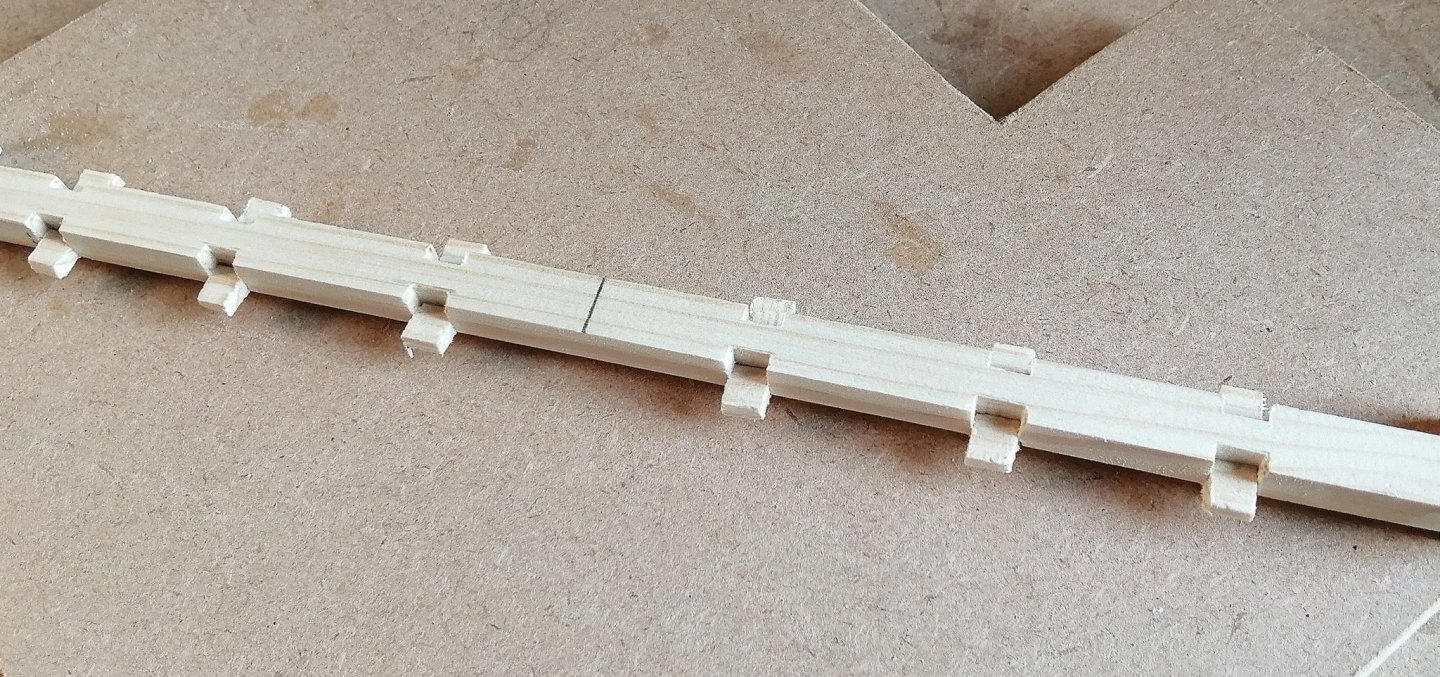
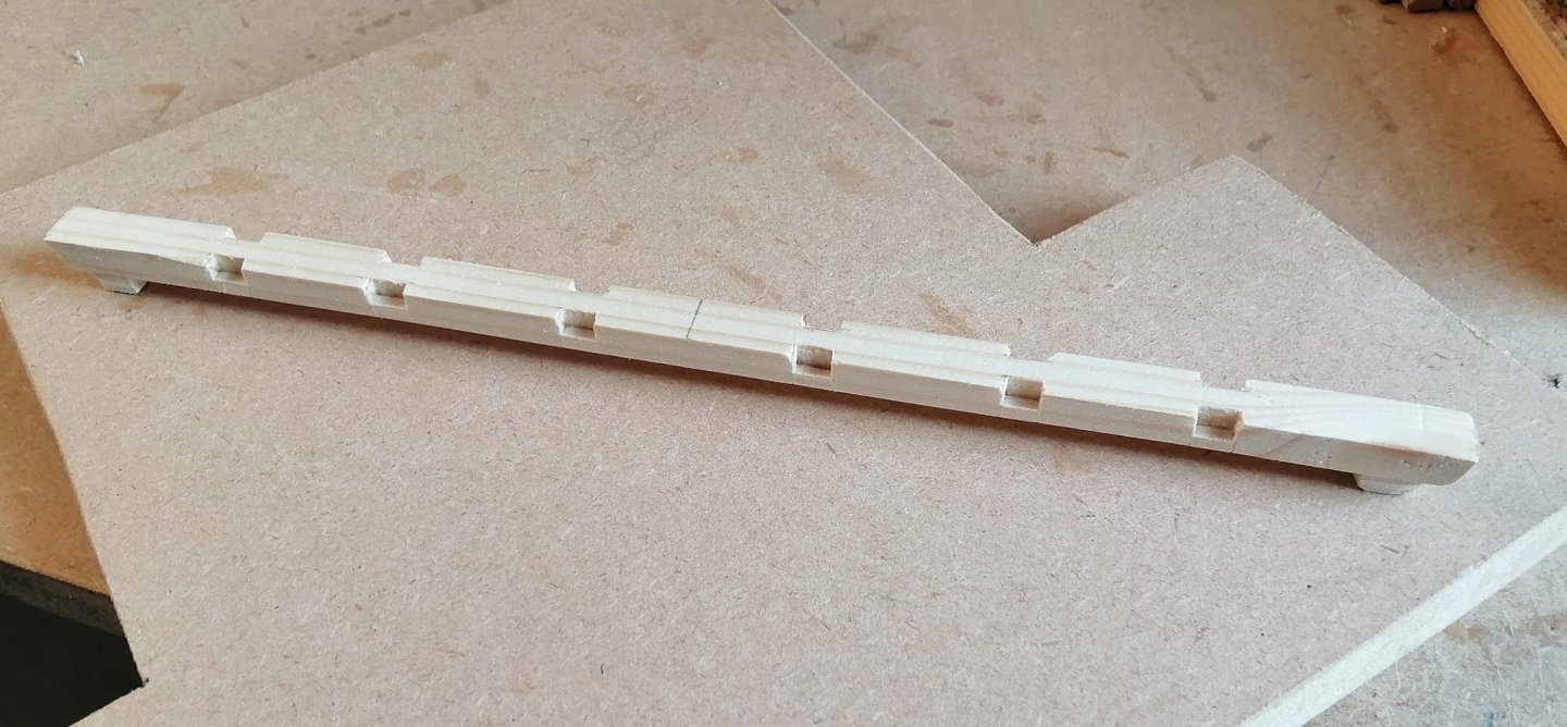
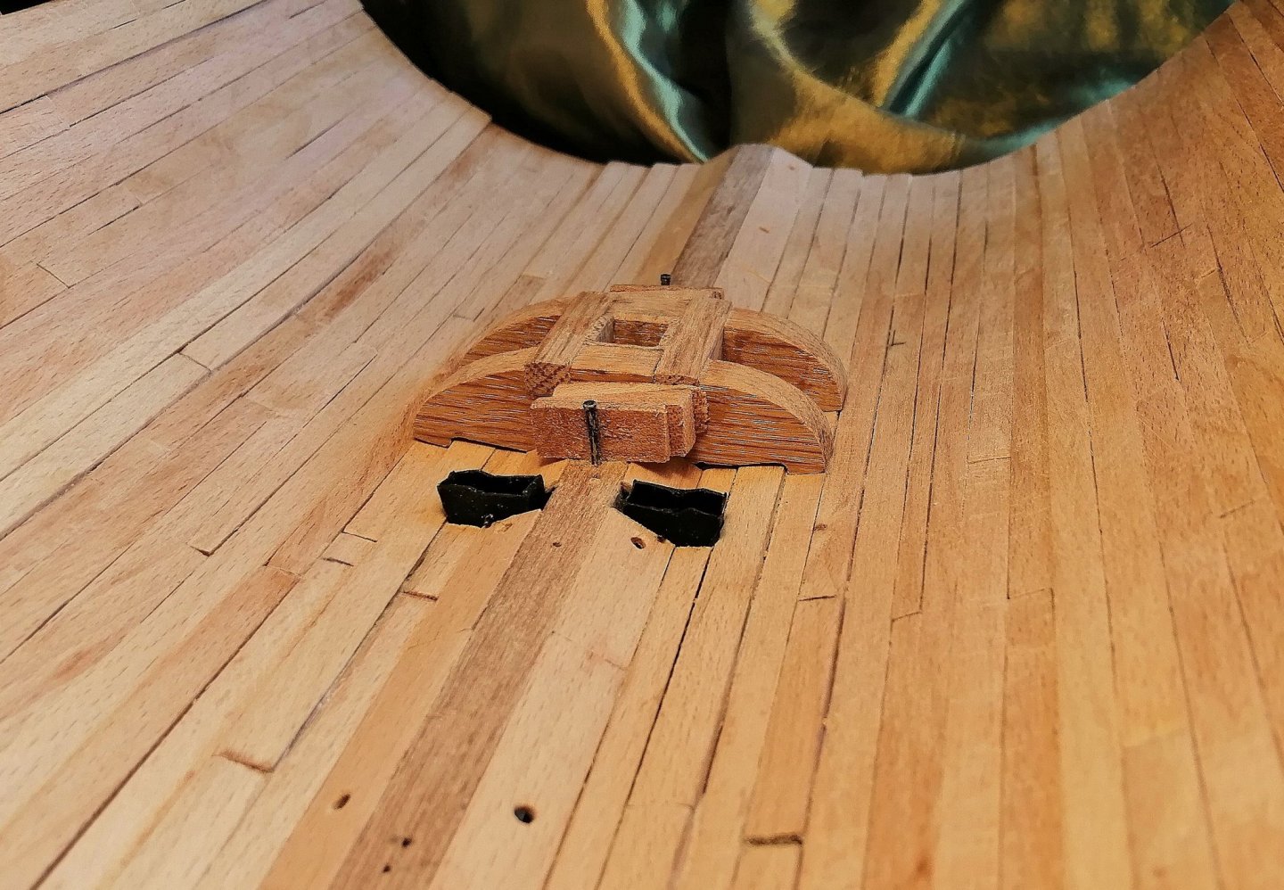
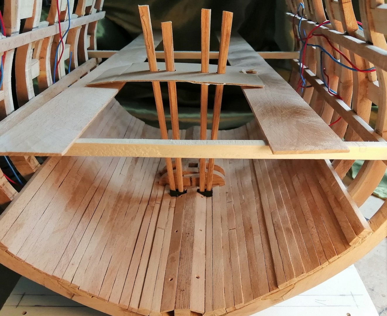
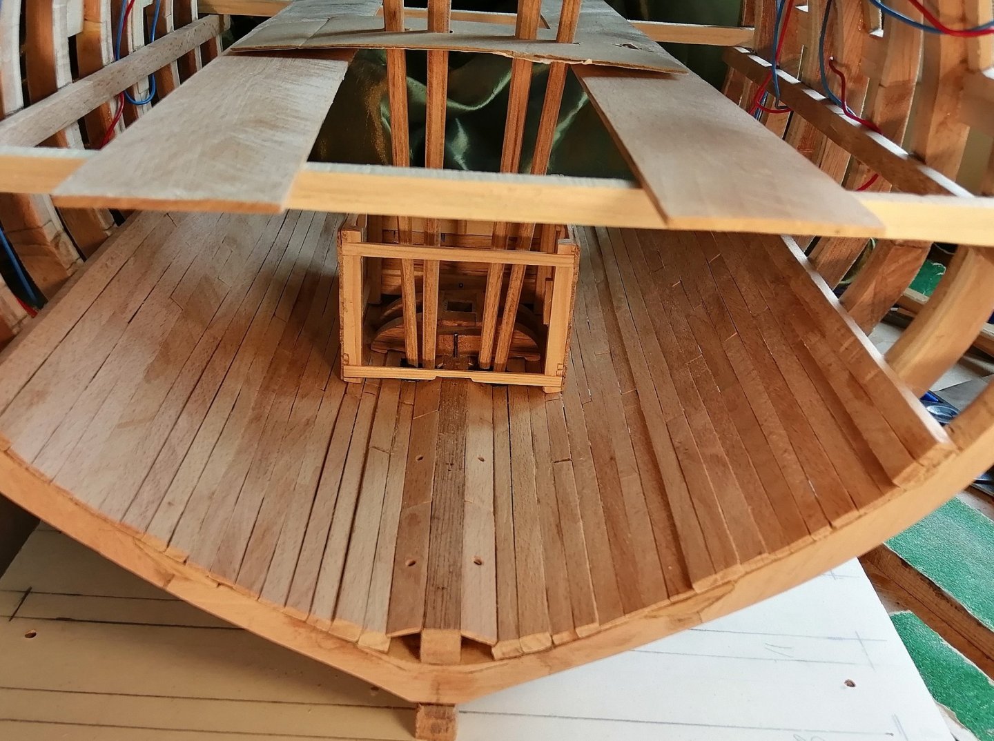
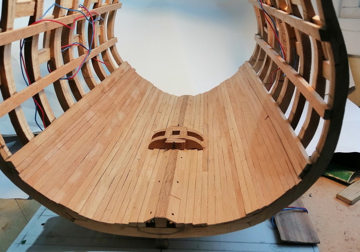
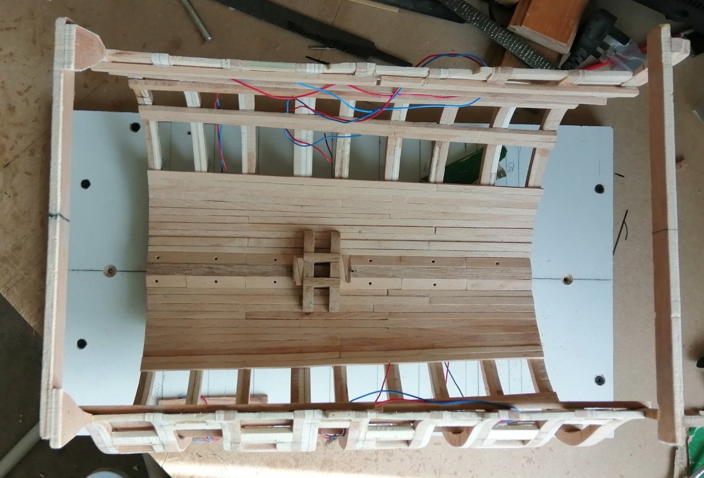
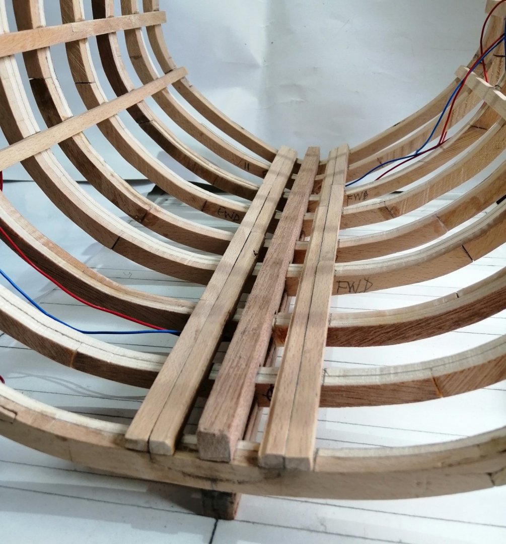
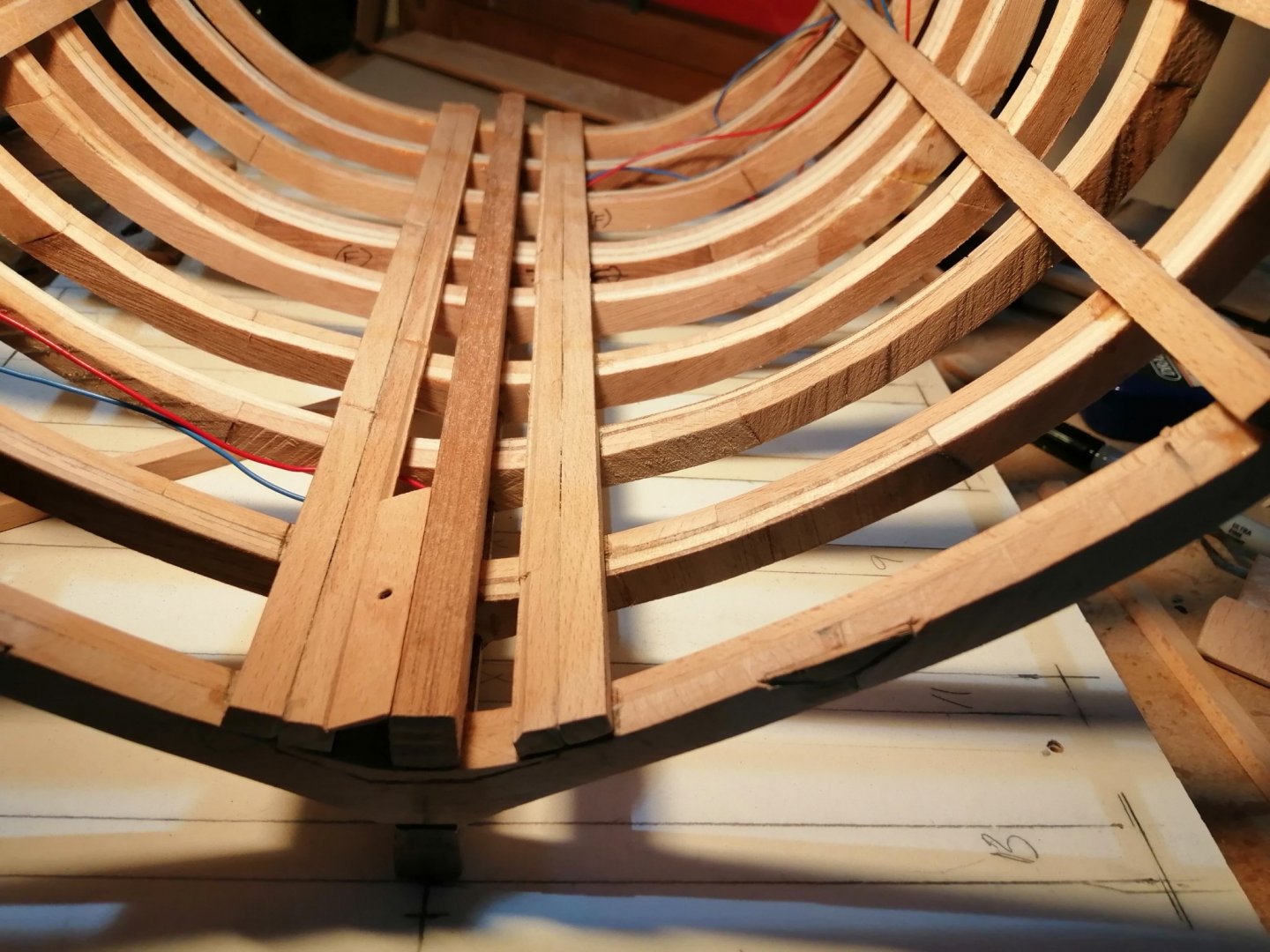
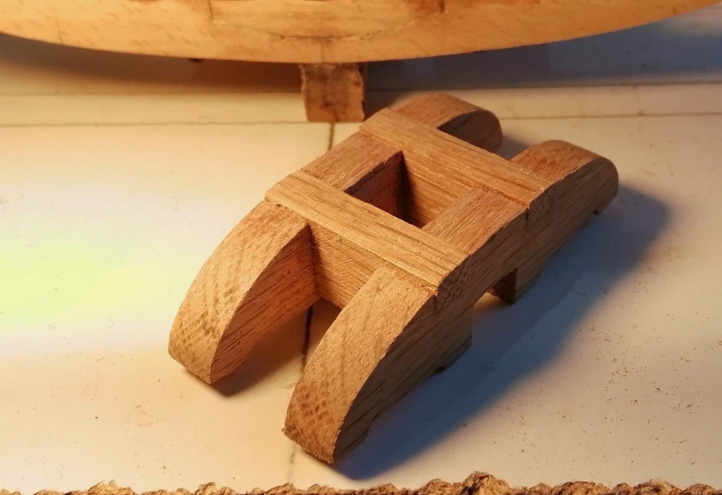
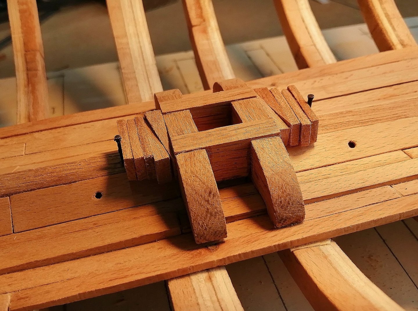
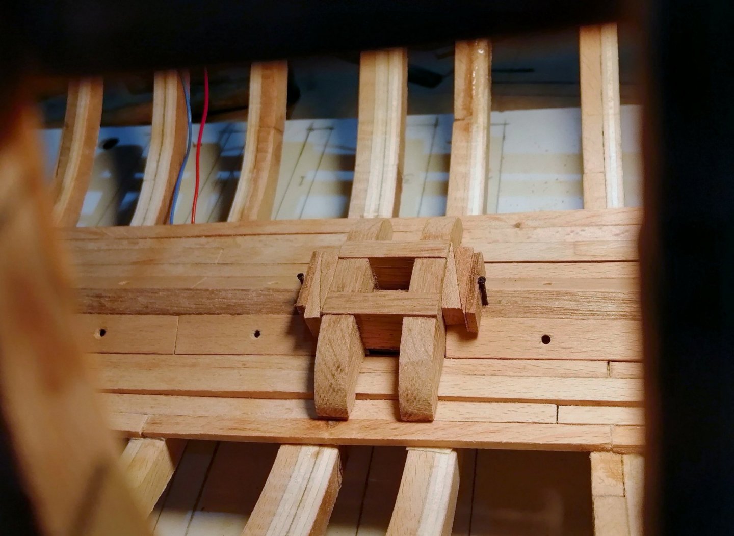
With orlop and lower gun deck clamps on I wanted to get the keelson on, but as I hope to have several lanterns lit at various places on each deck I led in the wiring for that first. Because this is going to be a longer section than 'normal' I hope to have lanterns towards the aft end as well as toward the forward end so I have led wires up through the keel (but under the keelson) near both ends. This pic shows the keelson in the clamps and the red and blue wiring at each end > . . . and after the epoxy has done its job > My plan is to conceal the wiring between the hull planking and the ceiling planking and bring the 'feed' for each level over the top of their respective deck clamps. (I hope it will all work eventually!) Limber strakes next. Before fitting these I placed each one in the mill, in the same jig I had used to mill the rebates in the keel, and ran a shallow 45 degree groove along one corner of each strake to make it easier for the limber board to locate better. It's not very clear what's happening in the photo above so this might make it a bit clearer > Then to the ship > Then the outer limber strakes > The first of the limber boards > With its neighbour > By the time I had fitted these two boards I realised it would be a good idea to make and fit the mast step before fitting any more limber boards > Step wedges and chocks > At first, fitted the step with three chocks on each side > But that looked like too much overkill so I removed two chocks from each side > With the remaining boards and a few ceiling planks fitted.


-
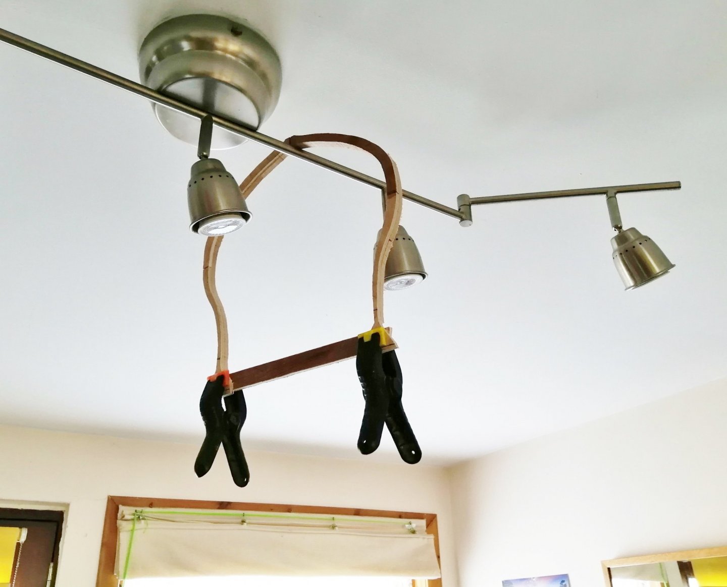
Alan, that's a very neat, and clever method of obtaining your woolding hoops! (Shavings are usually swept up for the bin!) That's a very neat bowsprit fairlead. I used that centre pin pivoting arrangement when I made mine but I used the mill -- I'm sure it would have been more difficult doing it the way you did it.
-
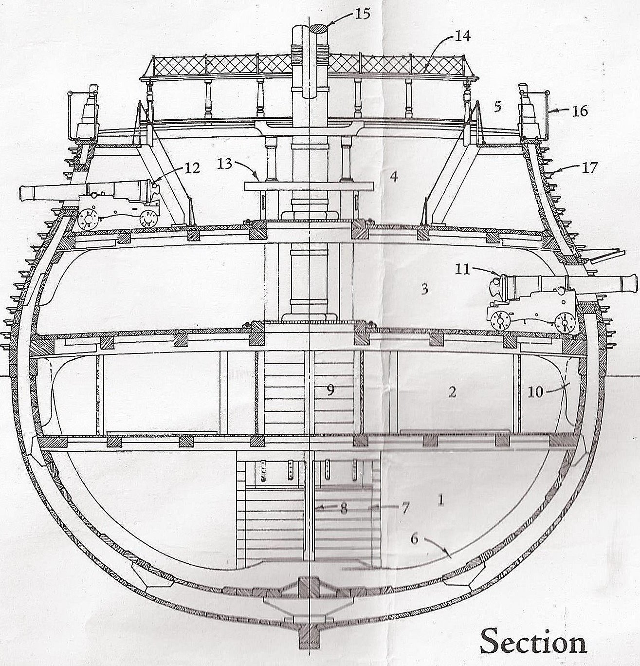
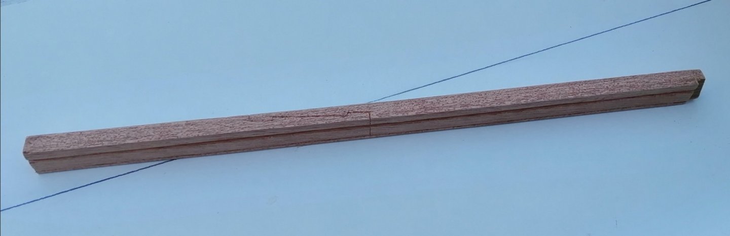
Hi Yves, thanks for your comment. I intend for the finished model to have a 'stump' mast as depicted in the Section drawing in the first post above, so the final size should be around :- Length = 13.4" 340mm Width = 11.6" 294mm Height = 11.6" 294mm After my previous build at 1:80 it's good to be able to stretch myself a bit with a section at almost twice the scale!
-
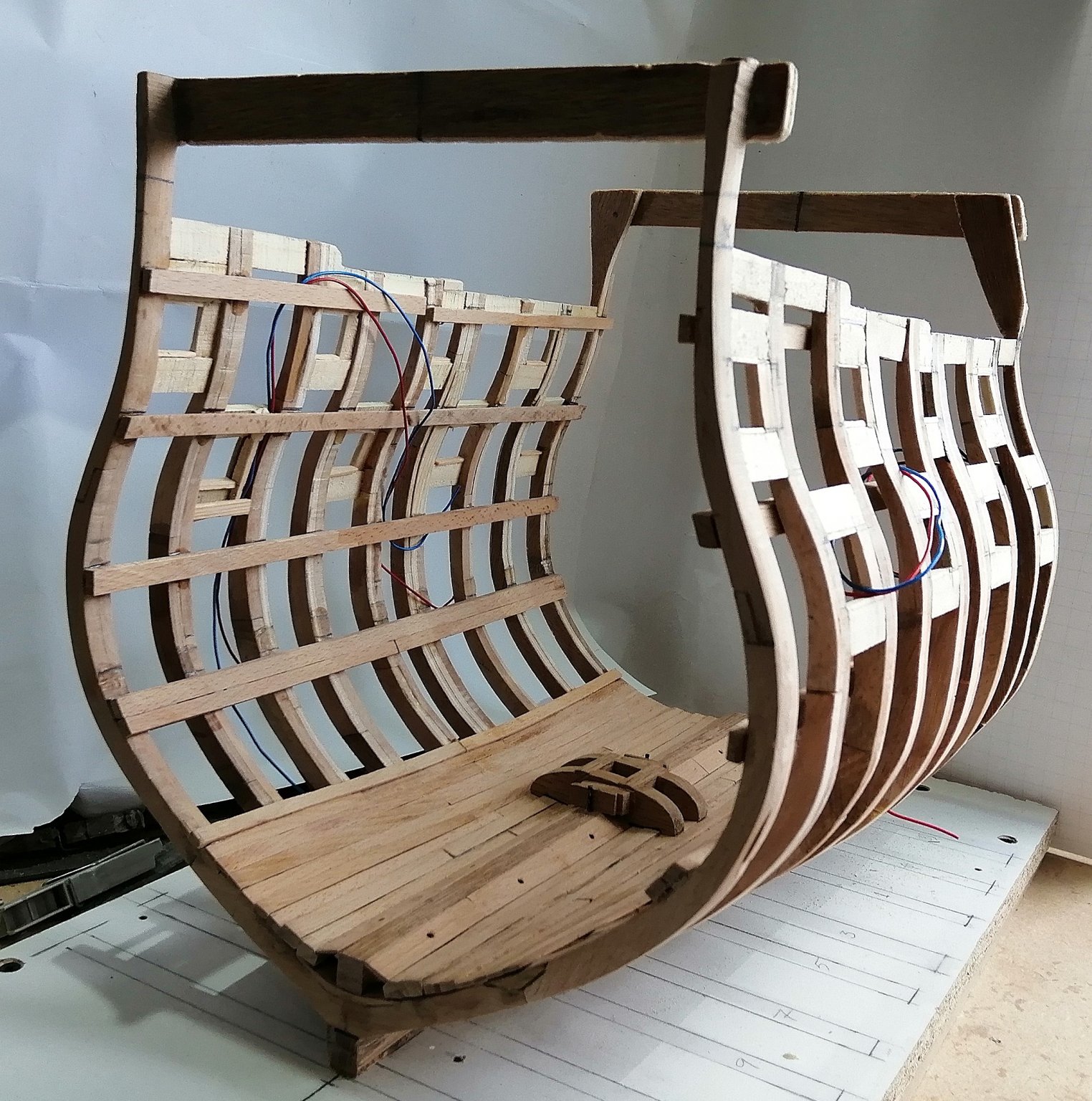
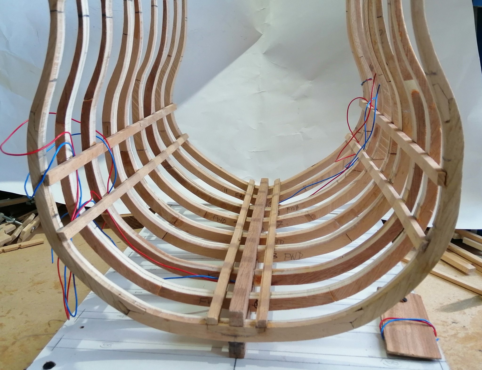
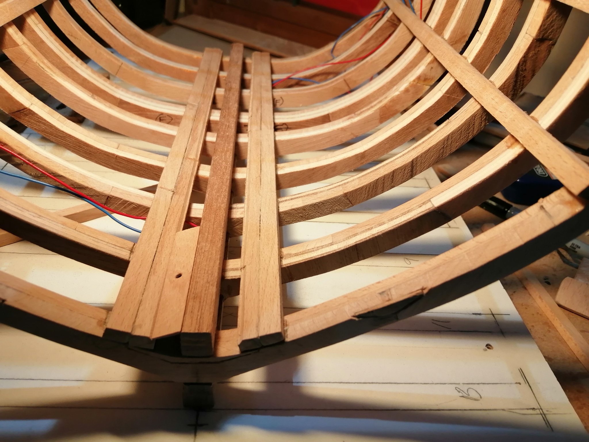
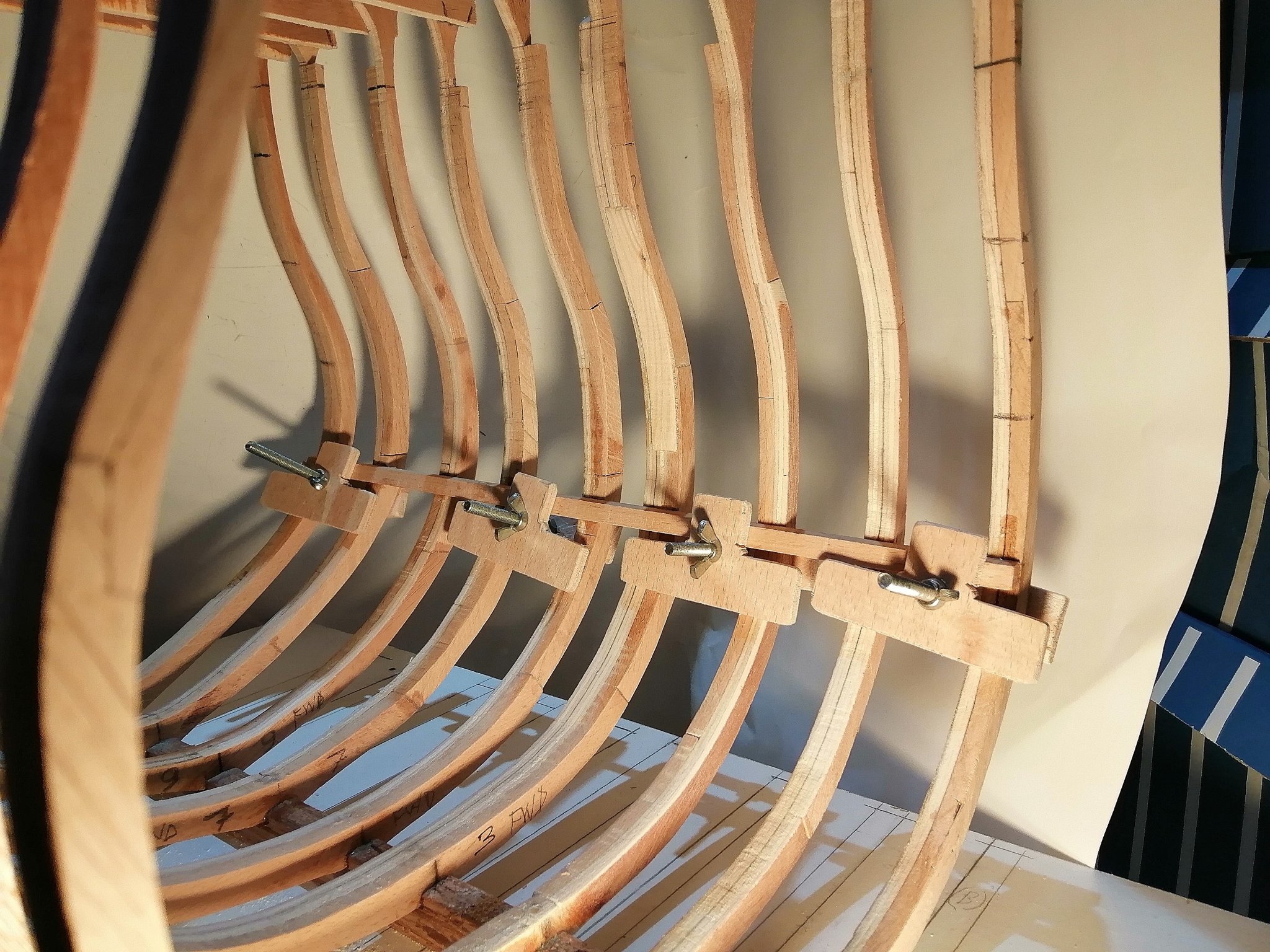
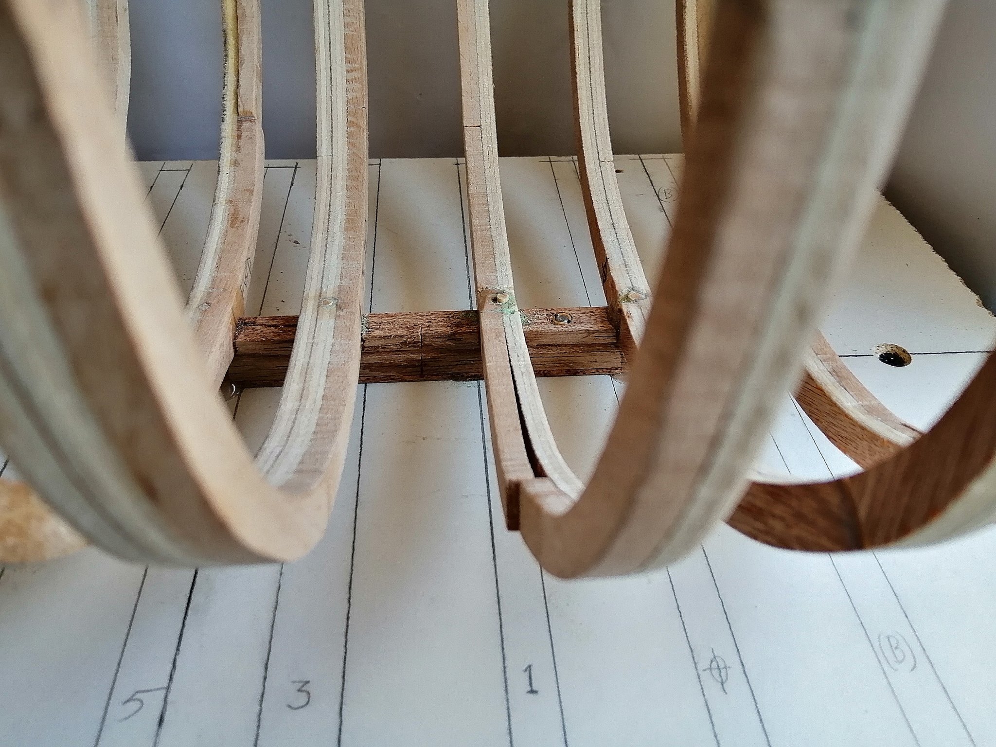
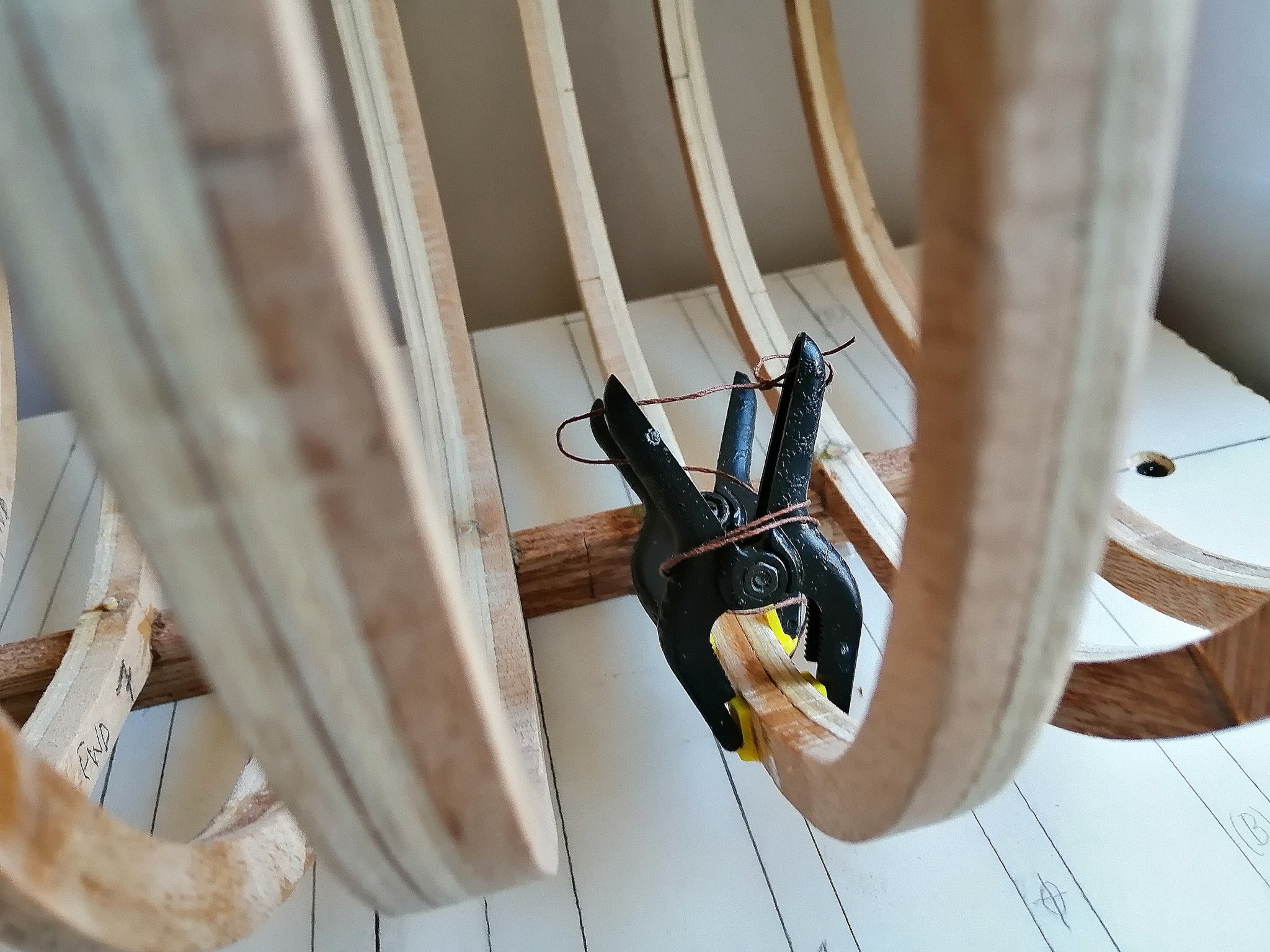
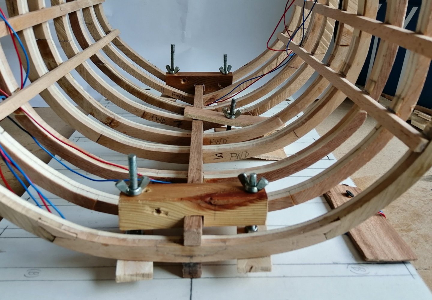
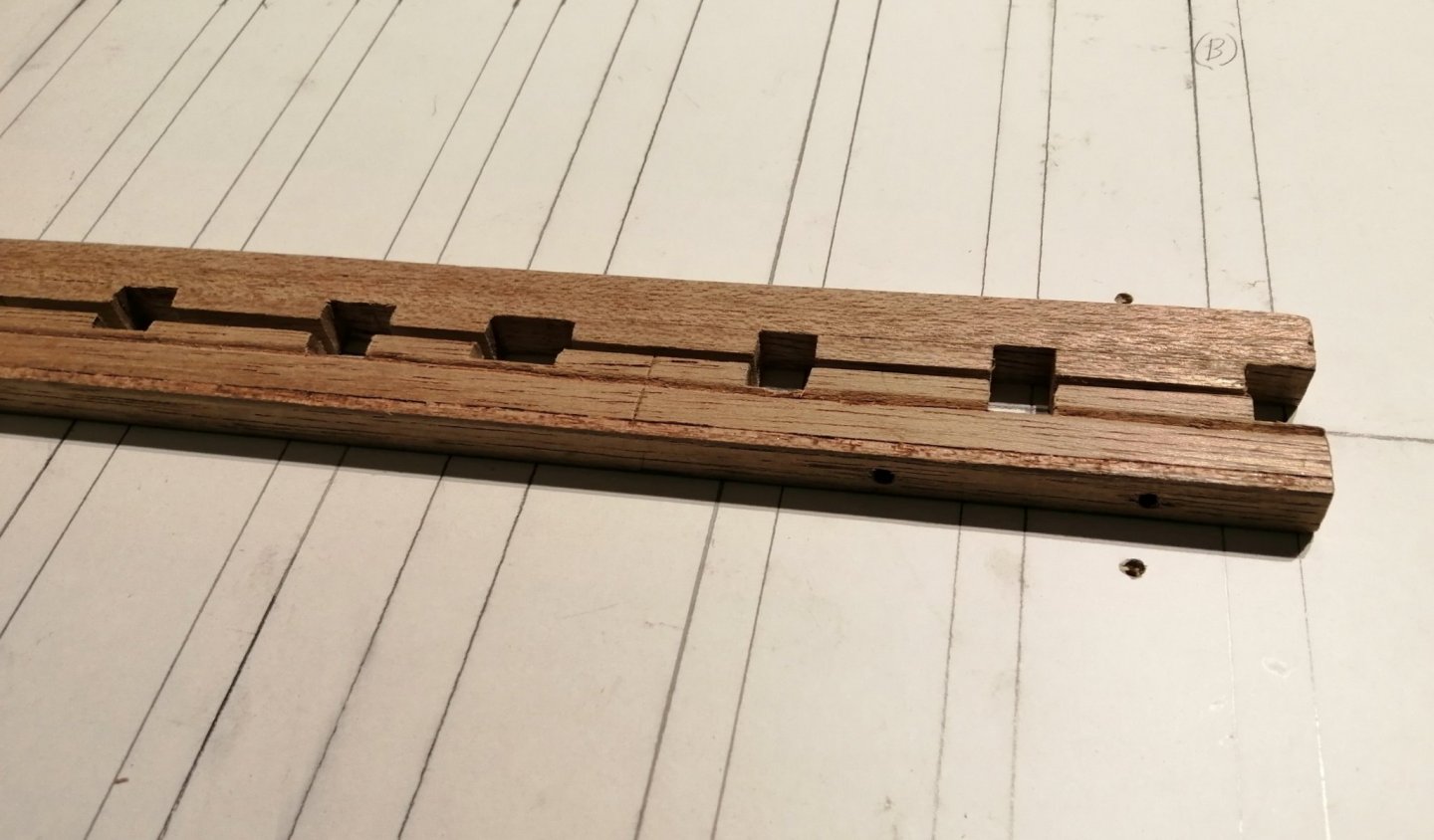
The keel and keelson have slipped past here pretty much without mention, so I should do that now. They're both cut from the same piece of mahogany as was the false keel. I already mentioned the cutting of the rebates in the keel. I should here mention the frames, as my frames do not have a cut-out/mortice that fits over the keel because I do not have any drawings of the frames. I merely created the frames using as a guide the only image I have of Leopard's frames that appears on the section drawing. Here's the floor timber area of that drawing > Since I made all the frames with floors like that, I decided to make large mortices in the keel and keelson so that the frames would have a secure place to live. The keel and keelson were clamped together and taken to the mill where the mortices were cut > Since I had dry fitted the frames onto the keel it was time to do it for real. First frame > Over three days the one frame became nine > First look along the outside of these frames shows that some fairing will be required but probably not as much as I was expecting. My main concern for the frames at this point was to get them stabilised somehow. My first inclination was to glue in fillers between the frame tops. The exact tops of the frames haven't yet been established so I decided that I'd try to get some of the deck clamps in place. My earlier "invention" for centralising the frame tops proved useful in helping to transfer the marks for the various deck clamp levels onto the frames. The levels for the orlop clamps were the first > First mistake! I carefully measured the level(s) of the orlop deck heights fore and aft as there is around a 4mm difference between the two, transferred these measurements to the frames at four locations and glued and clamped the first deck clamp to the marks. While waiting for the glue to dry and measuring for the lower deck levels, I realised that I had glued the clamp at the level of the deck it was meant to support instead of the level at the underside of the deck beam. That epoxy resin is good! That first mis-placed clamp did not want to come off --- it had to be drilled through at each end and carefully prised off the other seven frames. New clamp made and duly attached at the correct position -- lesson learned! I previously mentioned that some joints had failed on a couple of frames before fitting to the keel. When sanding some of the frames (on the keel) another frame joint failed > My "T N P" glue fixed that > (For explanation of "T N P" glue see my previous post!)


-
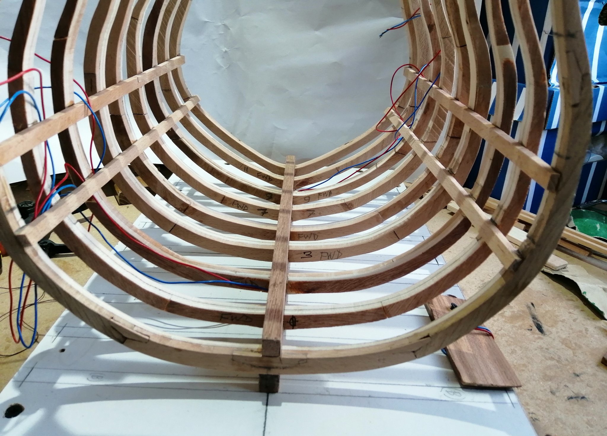
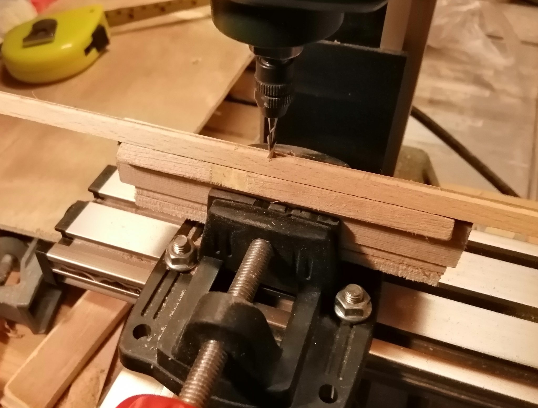
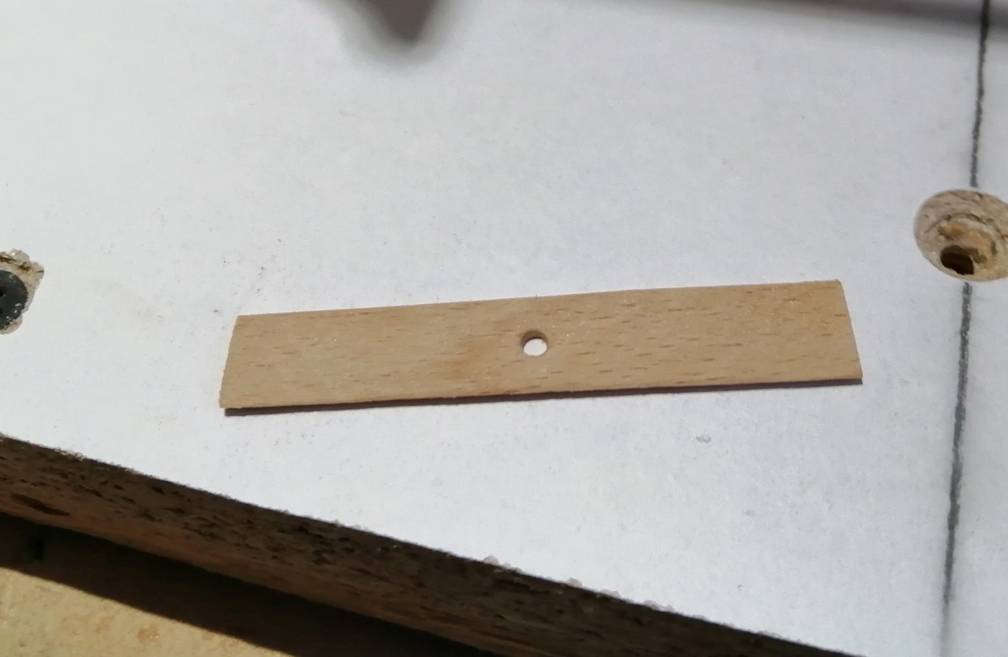
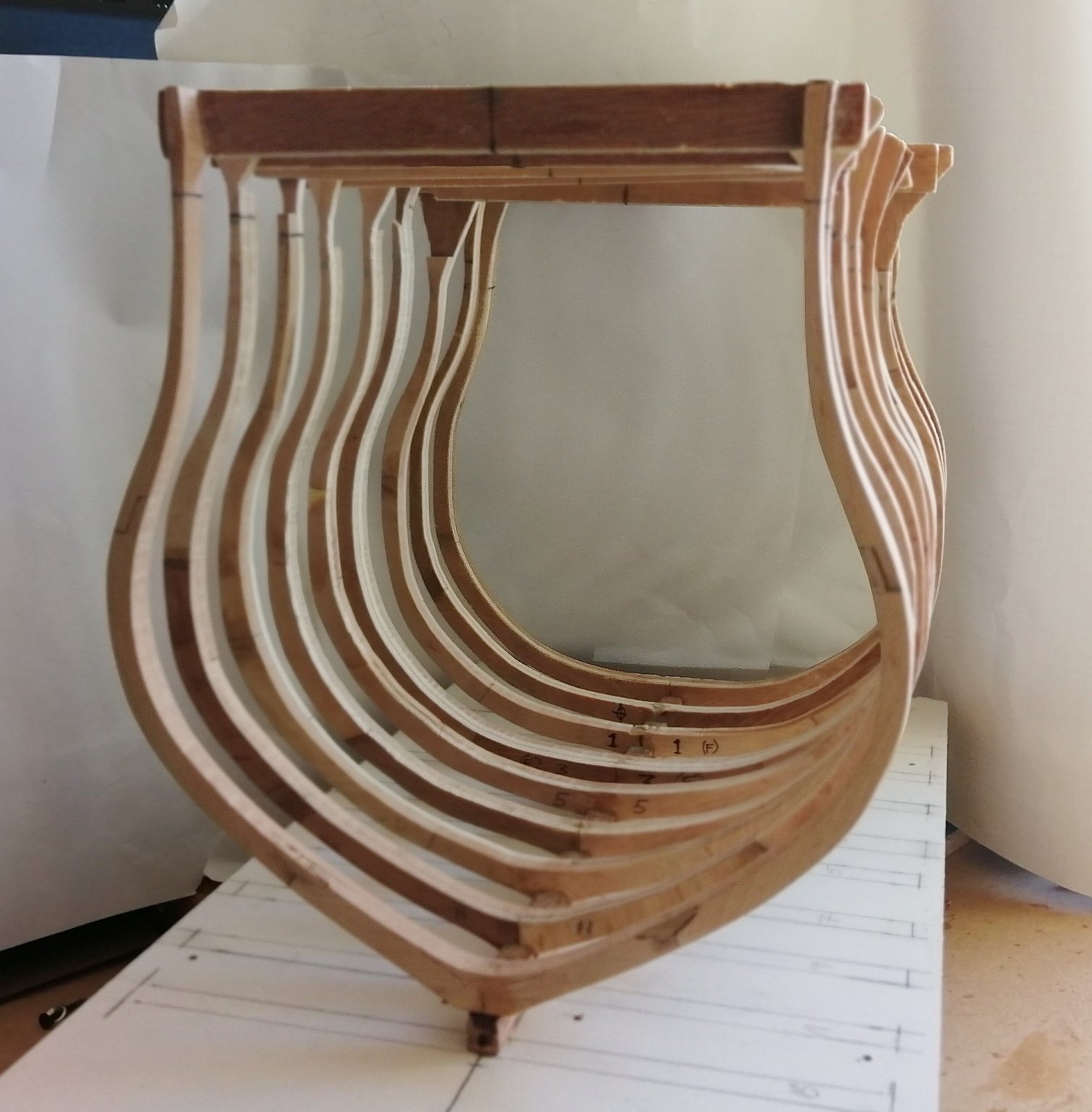
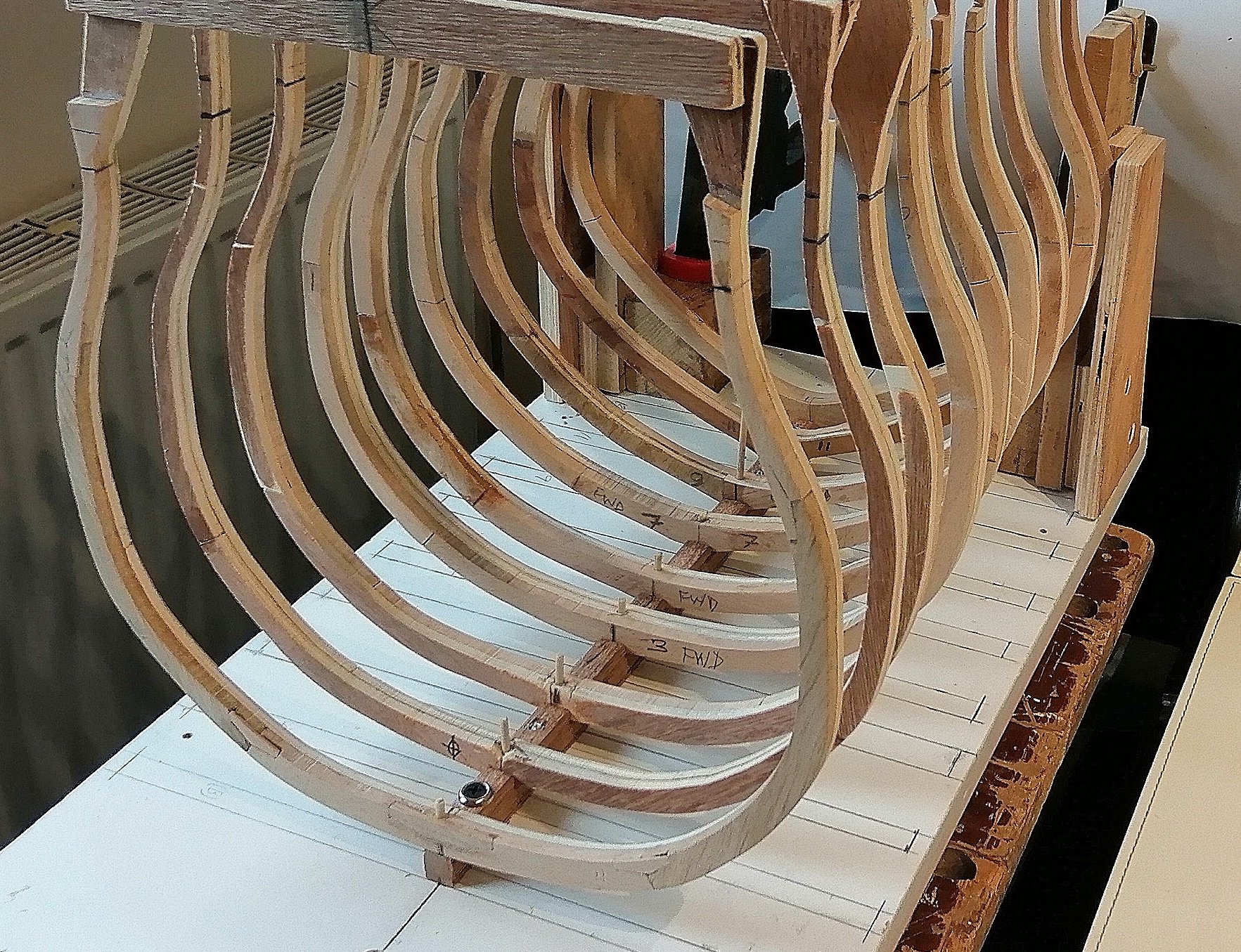
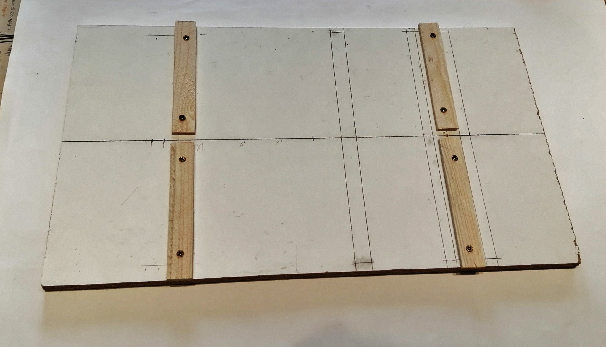
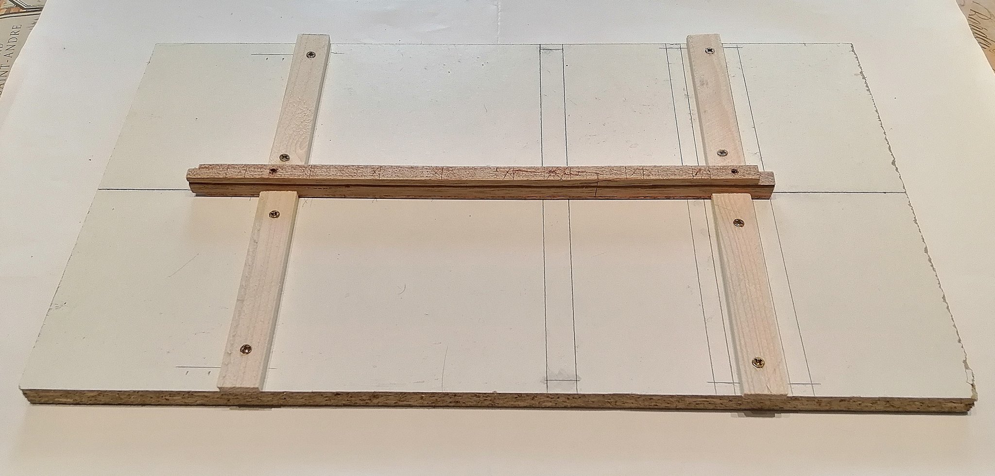
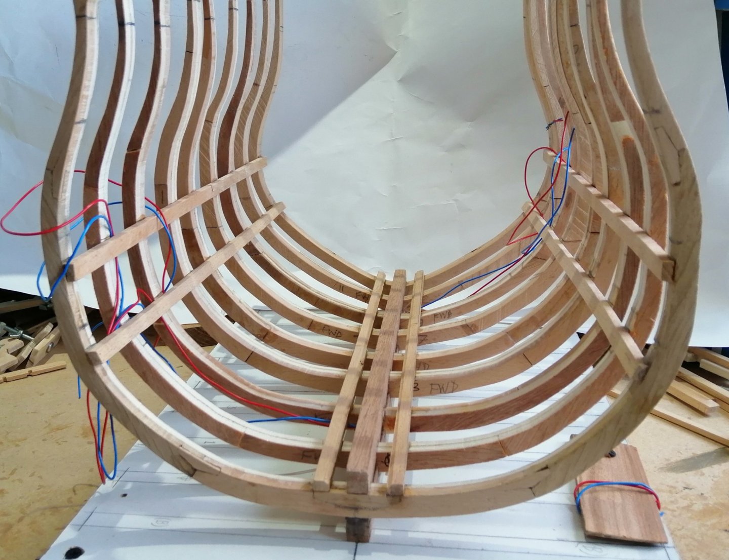
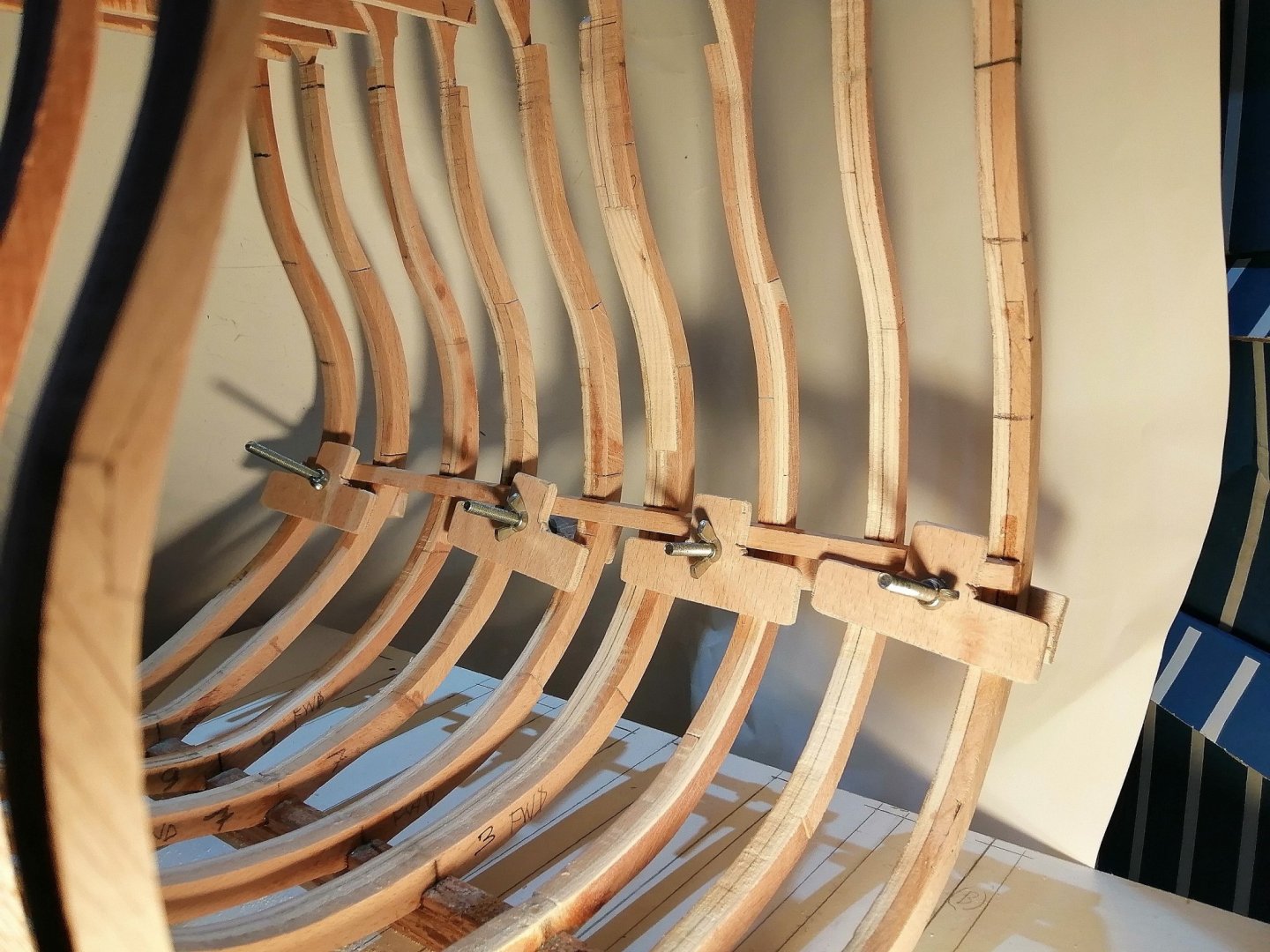
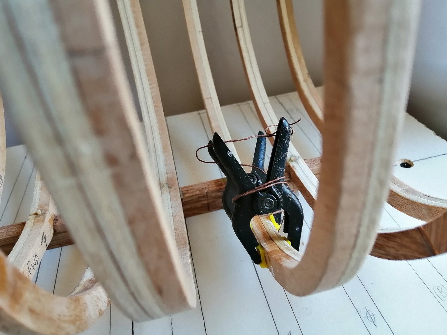
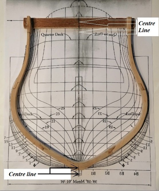
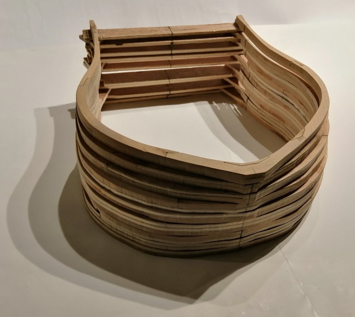
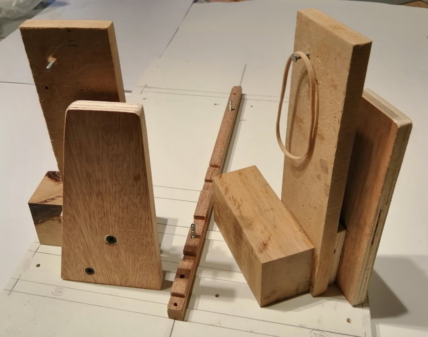
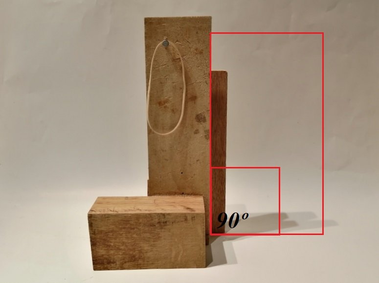
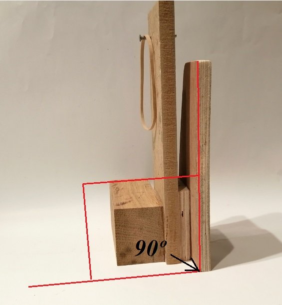
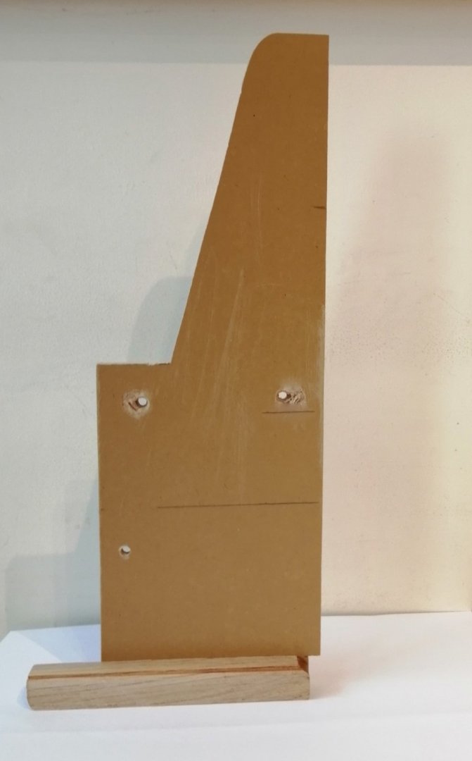
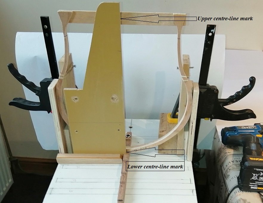
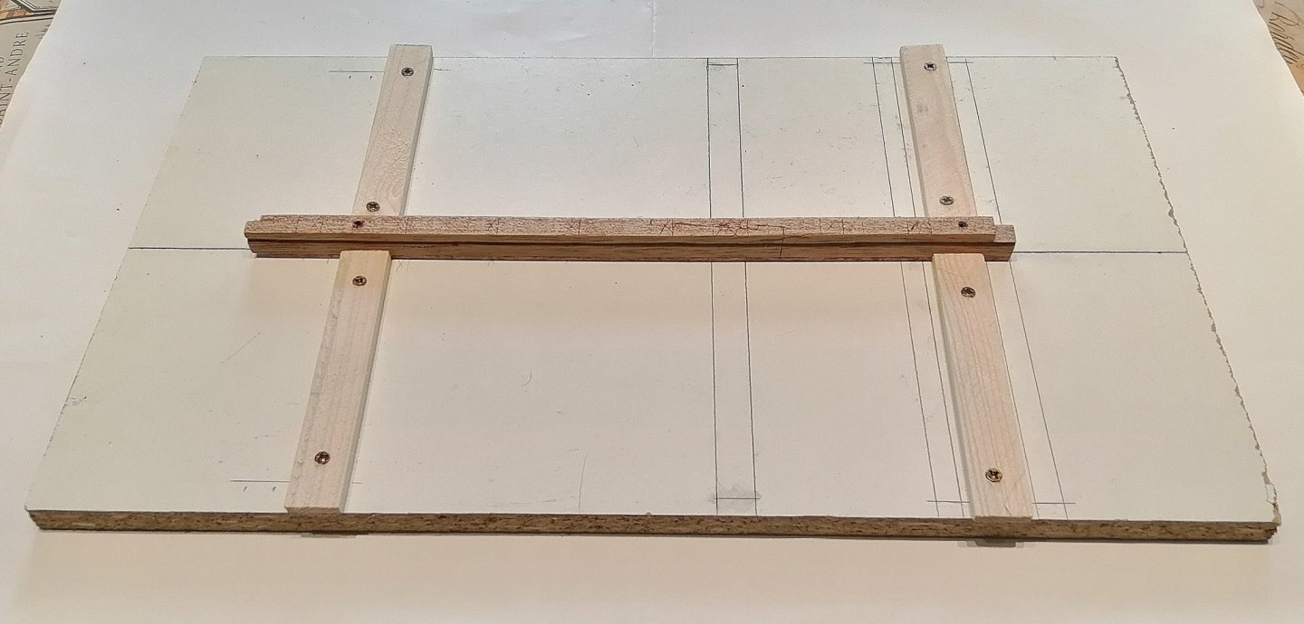
In three days I've been able to make the blanks of all nine frames. Each frame required 13 pieces to be cut and laminated in two layers then glued together. I used beech on one side of the lamination and plywood on the other side. After their visit to the bandsaw each frame was lightly sanded to get rid of most of the bandsaw marks, then as they're rather fragile I glued on a stabilising piece of plywood along their tops. A frame finds a safe place while the glue sets > Each frame was placed directly onto an uncut copy of the body plan in order to establish the centreline on the floor timber at the keel as well as on the stabilising piece at the top > Then there were nine > Building a framing jig is something I've never done . . . don't know how to . . . and have no plans or instructions, so that wasn't going to happen. Another means of keeping the build square and true was needed. After considerable time spent thinking about this I decided on these > An explanation may be required here. I'll try. These two "things" are mirror images of each other and each have two vertical pieces of ply that in turn present a 90 degree angle to the melamine base. Hopefully the 2 following photos may make it clearer > This next photo shows the two 'jigs' on the baseboard along with one of the frames > These two jigs ensure that the frame is perpendicular to the base in a fore to aft direction. To ensure that the top of the frame is definitely centralised across the keel I made this (the holes mean nothing - they were there before I used the board) > This piece of board has a factory cut perfect right angle corner - - the notch cut out at the bottom corner is to allow the board to be placed against the keel and is shown in the following > And (in theory) works like this > I used these 3 jigs with each frame in turn to establish their position on the keel and drilled a 3mm hole for a 3mm bamboo skewer 'dowel' to assist with the final gluing of the frames onto the keel > I wanted to see how the frames might look on the keel so dry fitted them all onto the keel and placed a dowel down through each one. I was a little surprised that just a dry dowel held the frames in a fairly stable position > That's quite encouraging for the actual glue-up. . . . and on the subject of glue-ups - - - I started gluing the frames with PVA glue and fairly quickly a few of the joints failed. I've had the occasional failure with that PVA previously so I had to re-do these failed joints. Having lost faith in the PVA I opted to use what I call my T.N.P. glue ---"Take No Prisoners" glue, otherwise known in the civilised world as "Epoxy Resin". No more failures with the epoxy!


- 66 replies
-
- 11
-
-
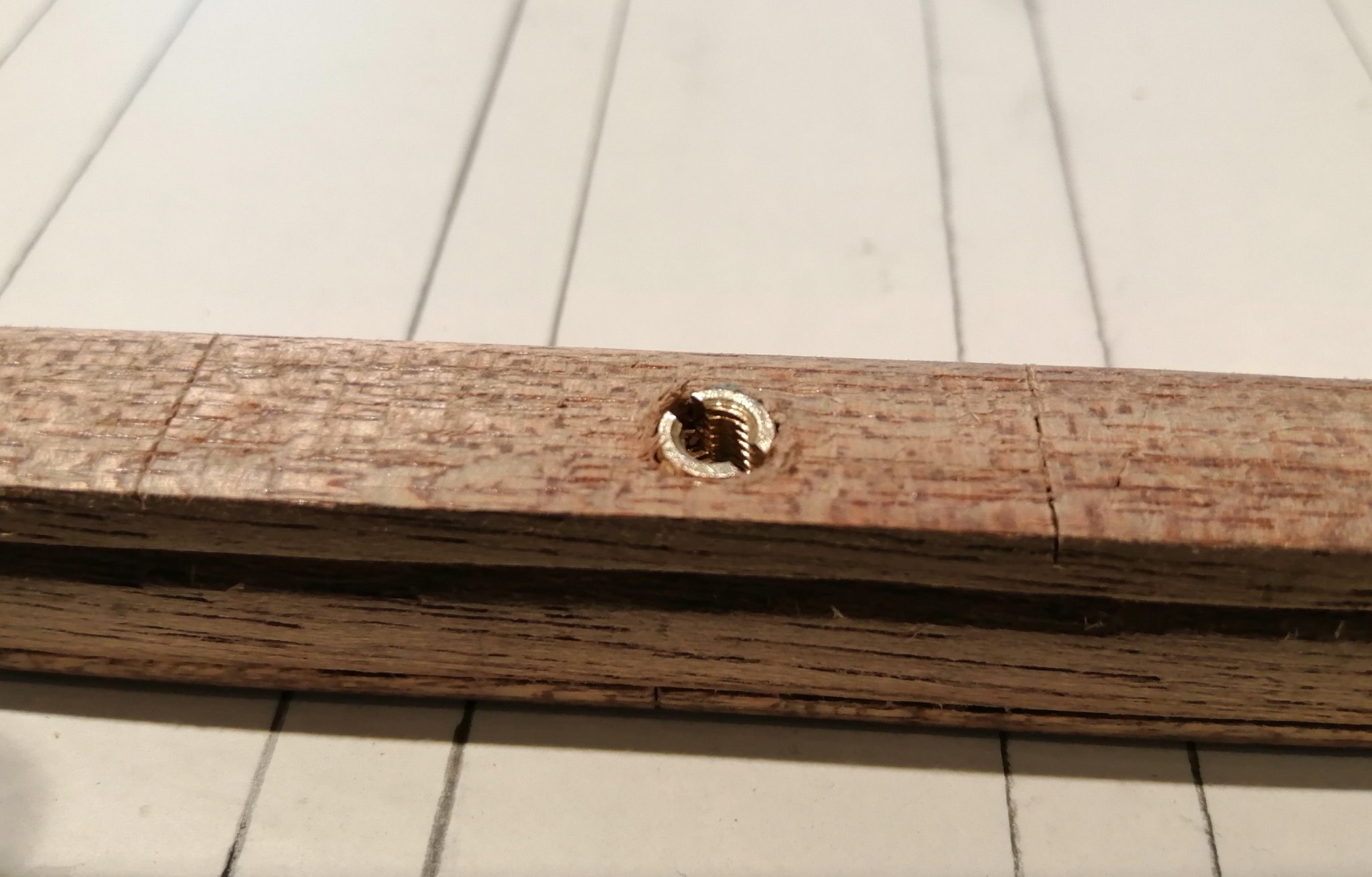
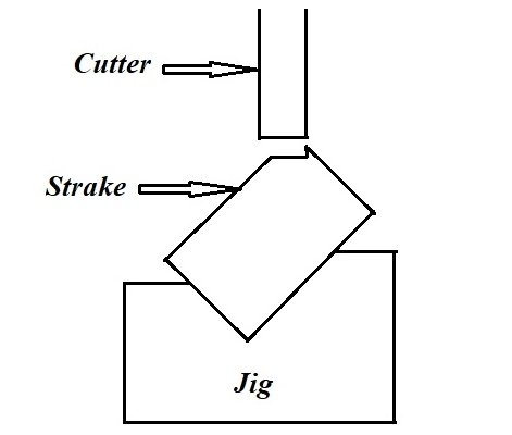
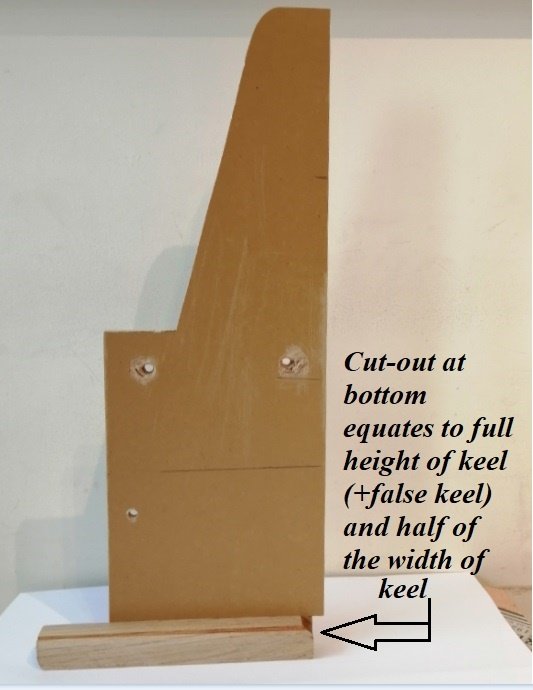
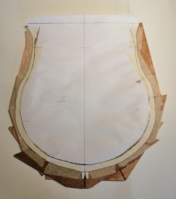
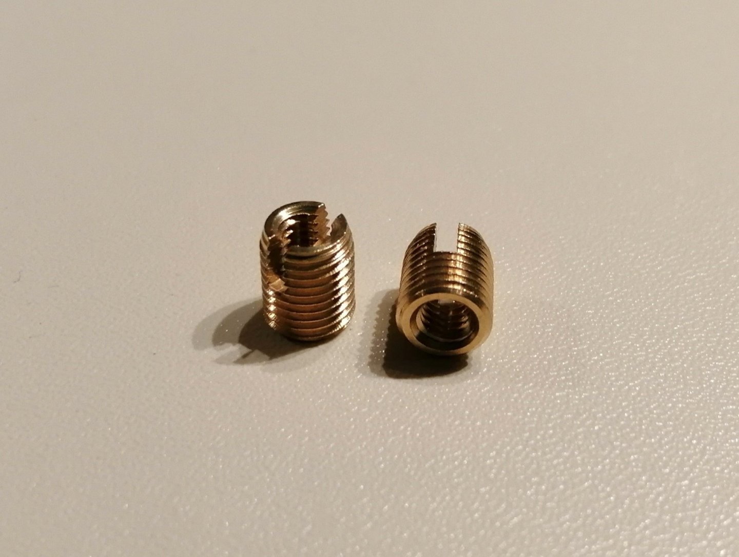
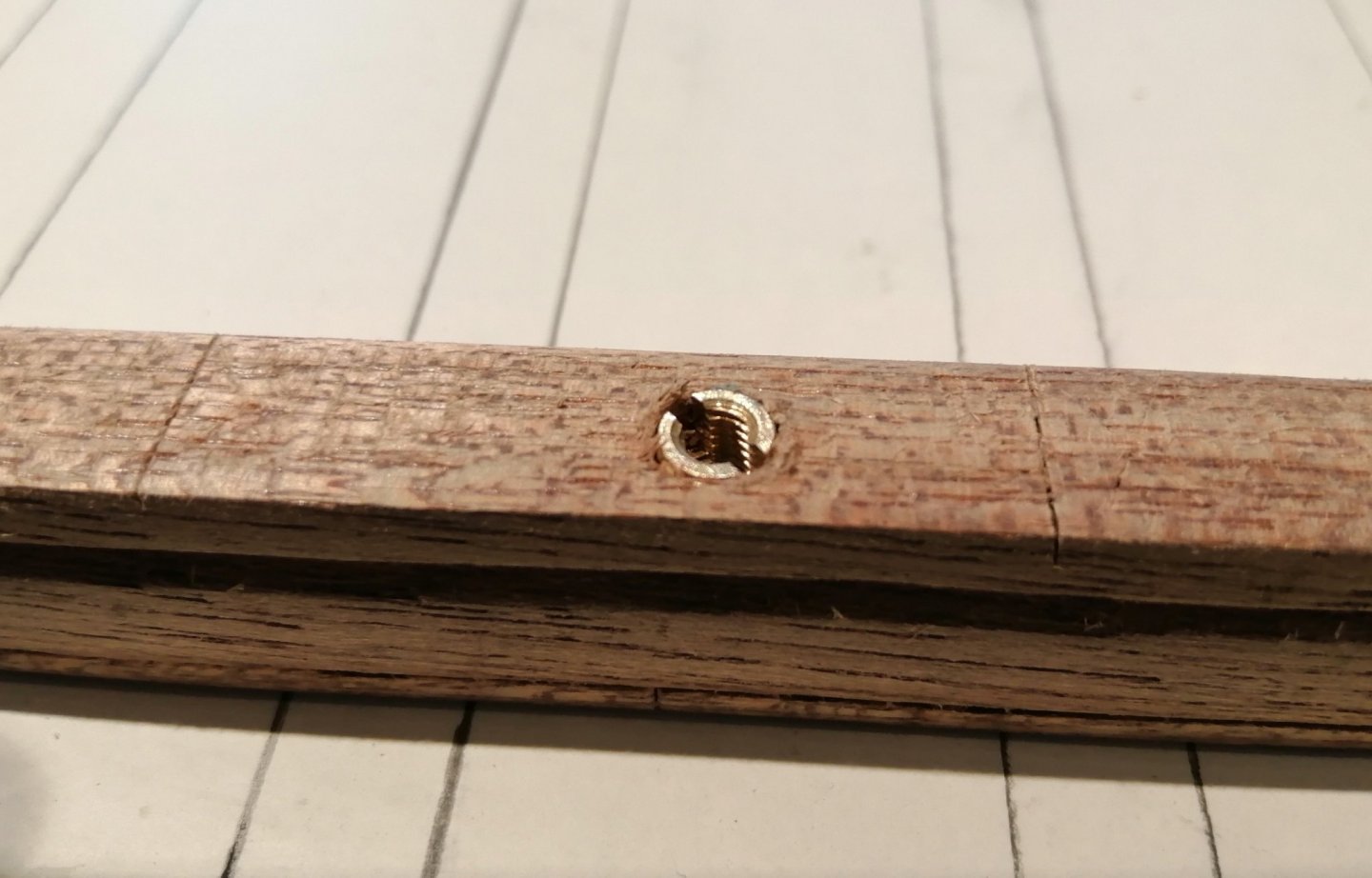
Sawdust made. Previously I had prepared a baseboard. I had considered using MDF but I had a perfect leftover size of white melamine board. It's very stable and flat and being white, is easy to draw reference lines on. Here with the centreline and 3 of the 9 frames drawn on. First sawdust came from the preparation of the keel and keelson. Cut the rebate/rabbet on the milling machine using this jig > I didn't use the machine in the usual way by using the travelling table but kept the table still and moved the workpiece (the keel) along the jig under the spinning cutter. The uncut length of the keel but with the rebate cut > . . . and 'dry placed' on the board to enable me to accurately position the screw-down locating 'lugs' > Next sawdust came from my first attempt at making a blank for my first ever frame. Each of the paper copies of the body plan were cut out at the appropriate lines for each individual frame. (At that stage only the outside of the frame is defined.) This is the cut-out copy for frame #11 (the keel is left on just for reference purposes.) > After cutting out, the copy is reversed and placed over, and attached by masking tape to the laminated blank for the frame. At this point I have to draw, freehand, the inside face of the frame > Then it is to the bandsaw to cut out the frame. Note to anyone who may consider this method in the future -- because I opted not to glue the paper copy onto the frame blank but used masking tape to do so, the inner face MUST be cut first. Cutting the outer face first would release the paper copy from the frame and the line of the inner face will be no more! (More freehand drawing would be required.) A light sanding of the inner and outer faces to remove most of the bandsaw marks. I expect to be doing more sanding of all the frames once set into the keel before any planking begins. In order to hold the keel onto the baseboard during construction I used these brass threaded inserts > They hold the keel very securely onto the baseboard and I hope to use them to hold the model onto its permanent mounting when finished >

-
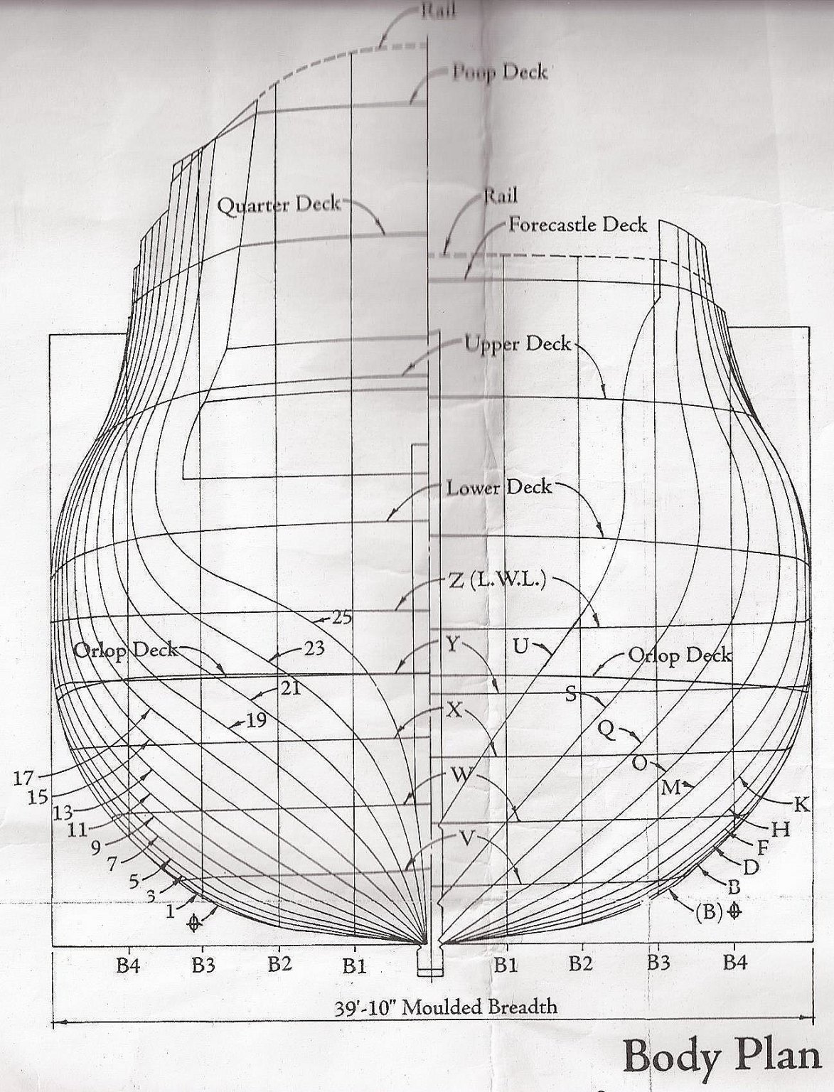
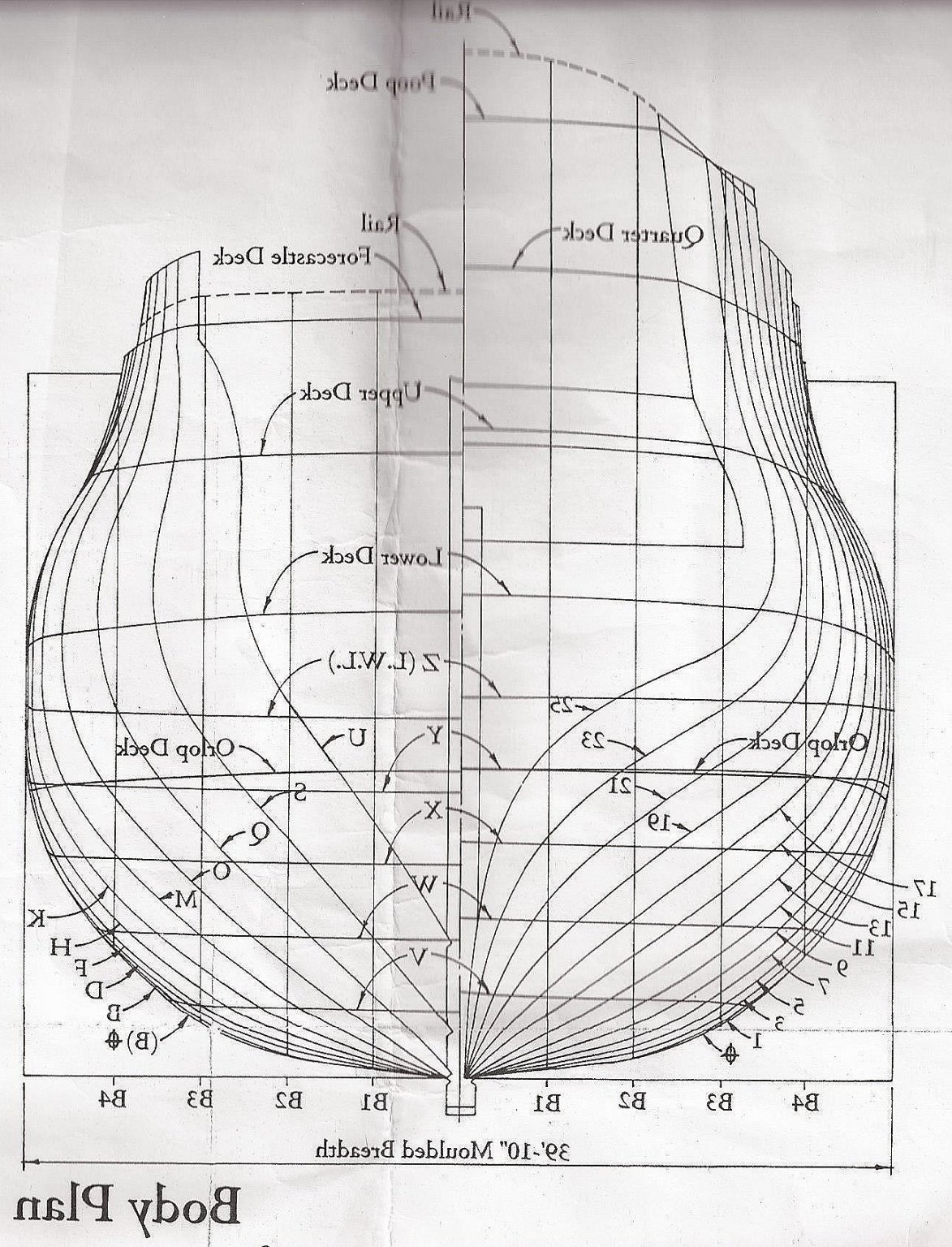
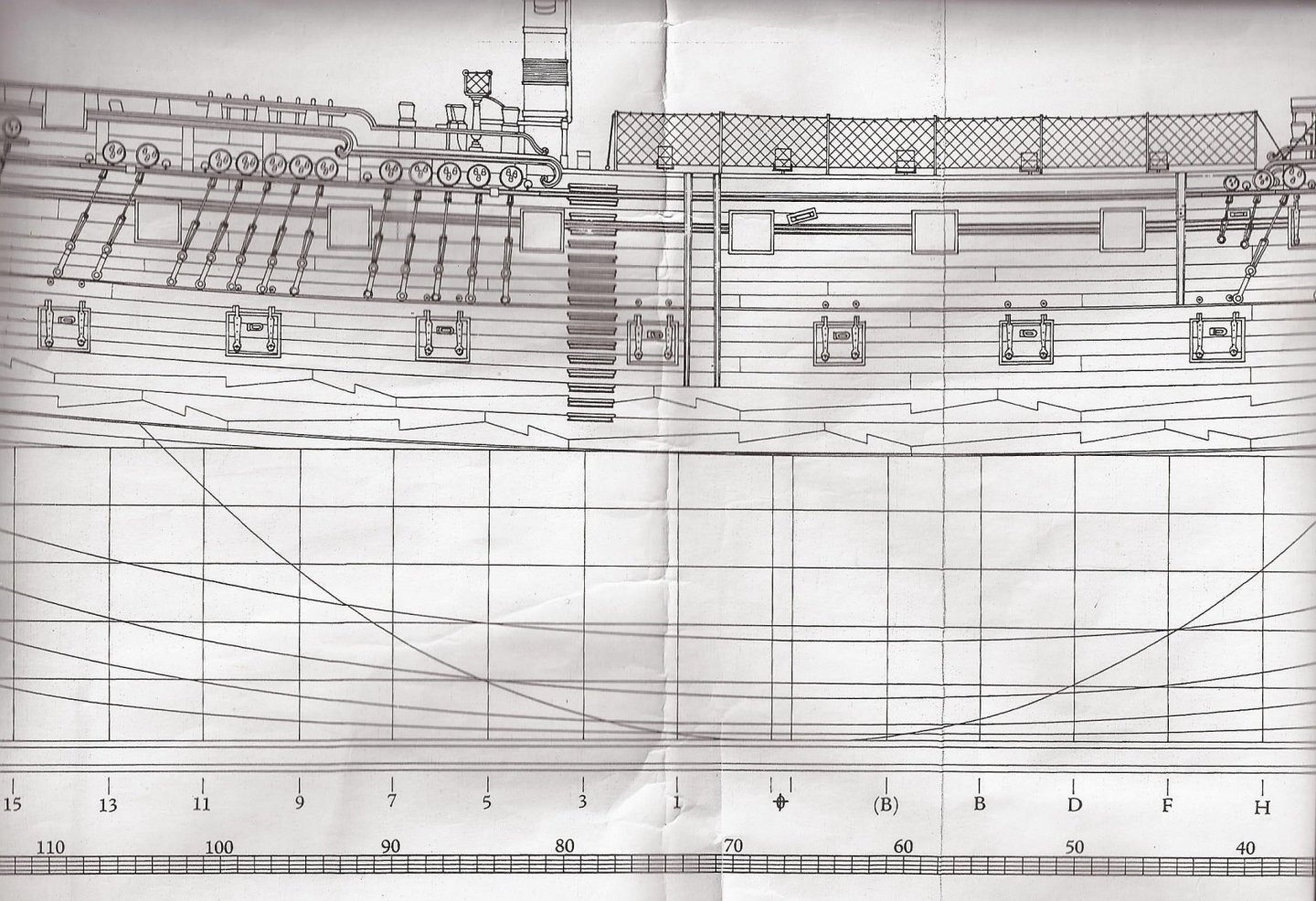
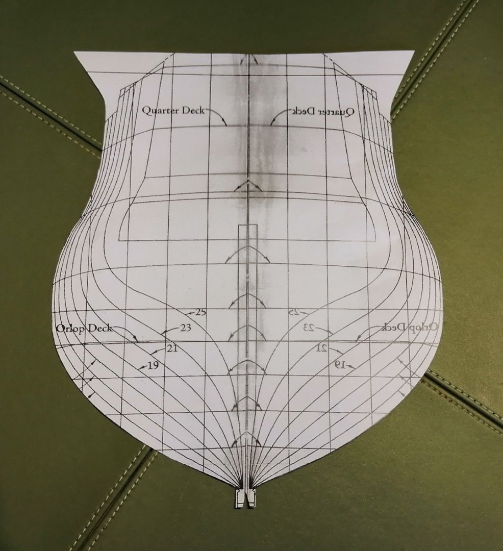
As the building of my other model, H.M.S. Leopard at 1:80 took the best part of 9 years, I didn't want to take on another full-on model of a complete ship. So, since I have basic drawings/plans of Leopard I'm going to have a try at a cross section. As a section will require a lot less space for the finished item I wanted to exploit that and have increased the scale considerably. . . . and to explain about the unusual scale of 1:44 - - - I had planned to have the previous drawings at 1:80 doubled and asked for that at the copy shop. The enlarged copies didn't quite come out at twice the size. At the widest point on the body plan the moulded breadth measures exactly 11 inches. Compared to the 'real width' of the actual ship at 39 feet 10 inches that works out at 1:43.45 --- so, its official model scale will be called "1:44". Okay, that's that out of the way. As for the actual parts of the drawings and plans that I will need, some modifications have to be made before I can even think about creating more sawdust in my hut. When I built my previous Leopard it was P.o.B. so the body plan was sufficient for creating the bulkheads but I have to modify that plan for creating frames. All I have is this >>> and one copy of a section at mid-ship >>> I will need more than the 'half frames' that are available on the body plan, so, I had the image flipped horizontally and made a few copies >>> I then cut two of the flipped copies down the centre line and pasted them onto 'right-way-round' copies and ended up with these >>> These two copies above were the ones that came back from the copy shop at almost twice their original size. (I had 12 copies of the aft frame plan and 6 of the forward frame plans copied.) The section drawing above is reasonably adequate as a rough guide to the basic shape of the mid-ship frame but I will have to make use of the body plan for the nine frames I intend to make. It won't be a fully-framed section but instead the frames will equate to the positions of the bulkheads 13 to (B) shown in the plan below >>> It will be a little longer than most sections I have seen as I want it to extend from just ahead of the companionway forward of the main mast back to the two capstans. As a section at this scale would have a full height mainmast at around 1.6 metres (over 5 feet) I intend just to display with a 'stump' of a main mast as shown in the section drawing. (second image in this post.) This project is requiring a lot more advance planning than did my previous build before the sawdust stage so hopefully I'll have formulated a definite route to go by the next post. (I have ideas -- just have to test them!)