MORE HANDBOOKS ARE ON THEIR WAY! We will let you know when they get here.
×


Bluto 1790
-
Posts
324 -
Joined
-
Last visited
Content Type
Profiles
Forums
Gallery
Events
Everything posted by Bluto 1790
-
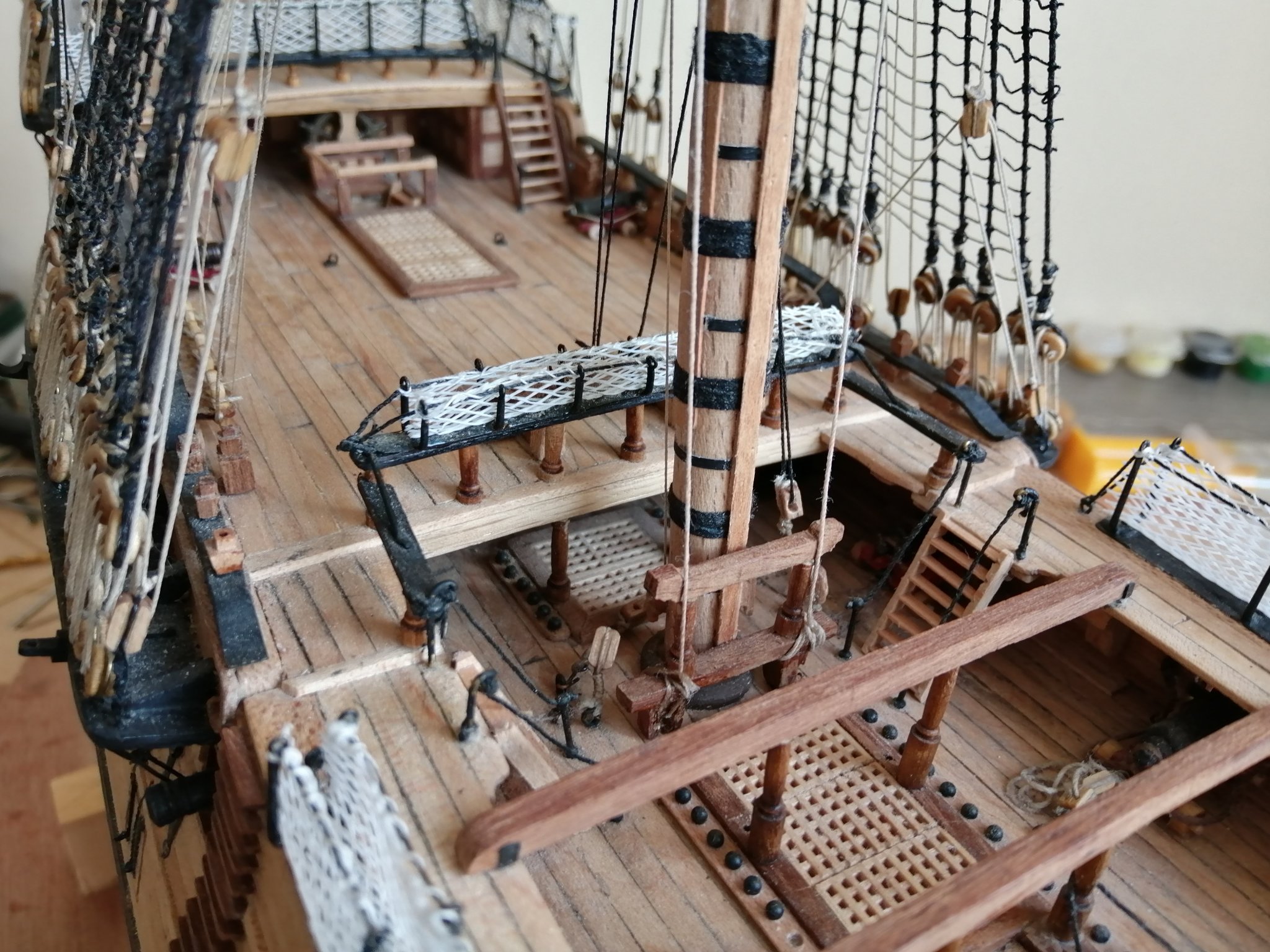
 You're on your way now, Tom! You're into the final stages now. Just a couple of questions: What did you use for belaying pins? They look very much in scale, unlike the ones I purchased which I had to try to 'whittle down' to get them to look more in scale. What did you use to maintain a uniform distance between the lower deadeyes and the upper deadeyes (at the channel)? (and I notice that you've added an extra couple of fore & aft pinrails on the Q/deck ~~ you'll need them as you're having sails on the ship!)
 -
Hi Tom, I was beginning to get worried about you! . . . but I see you've been busy! That's a whole lot of lines you have hanging there on the foremast. I'm glad you've labelled them! I can't quite do an accurate count of the belaying points you have around the foredeck but it looks like it must be at least 50? I see a few cleats on the foremast and a few pins on the aft guard rail on the fore top. Pins/cleats are like clamps -- you can never have too many! Are you planning on having sails on the ship? If so, I think you're well catered for in the way of belaying points. I hope you remembered to hang a block under the rear of the main and fore tops to catch the truss pendants' nave lines. Everything's looking great.
-
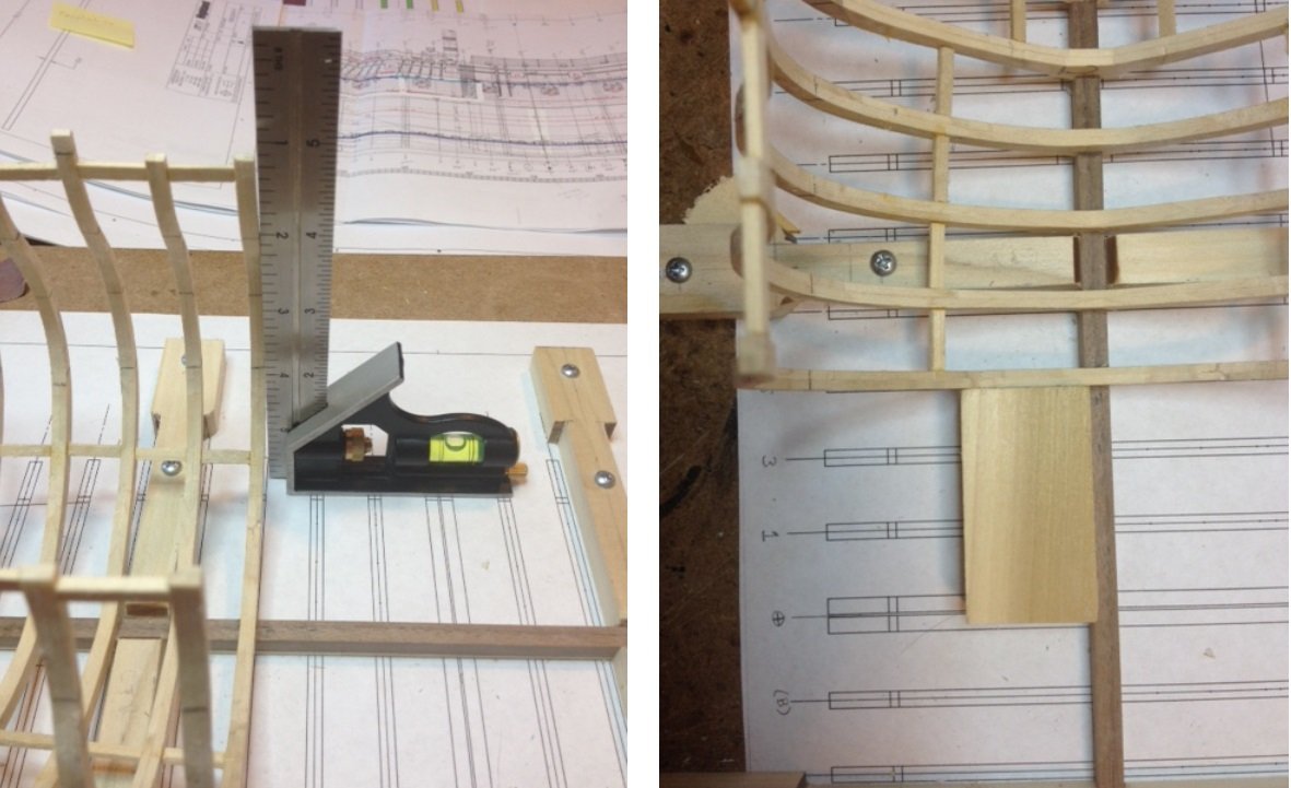
Hello Tom, I've just been having a look over your buildlog, and although I've looked through it before, I somehow missed something that I've just noticed - - - and, being a nosey guy, I just have to ask you :- In the first page of your log you posted a few pics of a plan drawing of the frames you used in the hull. Here are a couple of the photos > Where did you get that drawing of the frames? Did you draft it yourself? . . . and if you did, where did you get the information from? (I'm not really a nosey guy -- I just need to know stuff!)
-
How many riders?
Bluto 1790 replied to Bluto 1790's topic in Building, Framing, Planking and plating a ships hull and deck
Hello Mark, Thank you for your comments and helpful info. I'm not sure IF I'll actually go for a cross section but it would be a bit into the future. I've only ever built one ship model and learned a lot along the way. If I do go ahead with the cross section it will be at a larger scale than my Leopard and while I'll want to build it as well and as accurately as possible I won't stress too much if it's not up to museum standard (which it won't be!). -
Tom, that's a great collection of masts/spars you've got there. As it's now about 20 hours since you made the above post, I expect you've now got all the lowers fitted and secured with their shrouds and the ratlines tied?
-
How many riders?
Bluto 1790 replied to Bluto 1790's topic in Building, Framing, Planking and plating a ships hull and deck
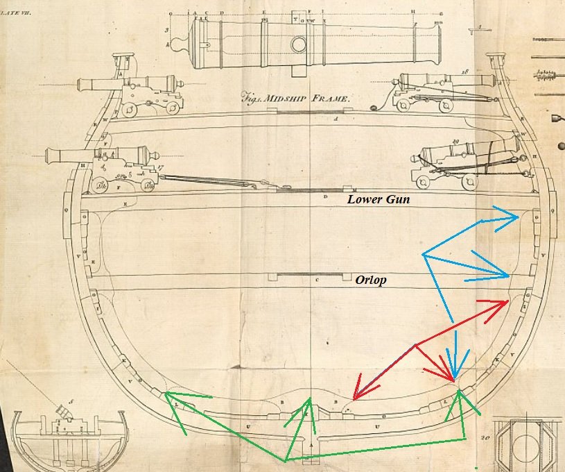
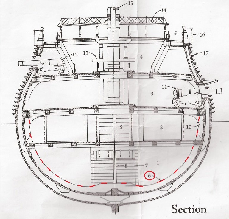
Hi Mark, I do have the Rif Winfield book - - I used it and its plans to build my Leopard. I must confess though that I didn't make much use of the drawing you refer to above as my model is a P. o. B. fully planked so I didn't include any internal details on the orlop deck as none of it would be visible. I assume you're referring to the following drawing where (I think) I've highlighted the 5 midships riders? >>> Also, while I await the arrival of the book I've ordered, I'm trying to get an understanding of how the riders were configured. I've re-posted your mid frame drawing and if I understand what I'm seeing, the riders look to be in 5 sections -- from just under lower deck level on port right down, over the keel and 'back up' to just under lower deck on starboard side? I've attempted to identify them and indicate their extent and how they 'overlap' each other in green, red and blue. Have I correctly identified them?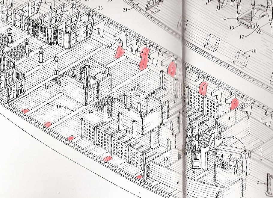
-
How many riders?
Bluto 1790 replied to Bluto 1790's topic in Building, Framing, Planking and plating a ships hull and deck
Druxey, Mark and Allan, thanks for the comments. Mark, I assume the section plan you posted above is a view looking aft so that starboard will be on the Left-hand side? My section plan in the opening post IS looking aft so is it standard practice to show these kind of views always looking aft? I have ordered a copy of 'Anatomy Of Nelson's Ships' from Abebooks. (There were a few copies on their site that were reasonably priced -- and there were a few that were unreasonably priced ! ) -
How many riders?
Bluto 1790 replied to Bluto 1790's topic in Building, Framing, Planking and plating a ships hull and deck
Hello Allan, thanks for your response. I've had a look at the link you posted and, as seems to be common with so many of these very old drawings, it's very faint and difficult to see things clearly. So I brightened the image to try to make it clearer - - - but I'm still not sure how to positively identify the riders from the image. I've reproduced it below and have inserted my own numbering 'system' hoping you (or anyone) can indicate the points at which the riders are located. (It looks to me that there may be two at points 2 and 3 [abaft the mizzen mast step] on the drawing --- but I'm not at all sure ???) <<< and even if that's correct, where is the third one ??? The area I'm considering for a cross-section is from around number 7 (to include the aftmost capstans) to number 15 (to include the companionway from the main deck down to the upper deck), so if there are any riders in that section it would be good to know!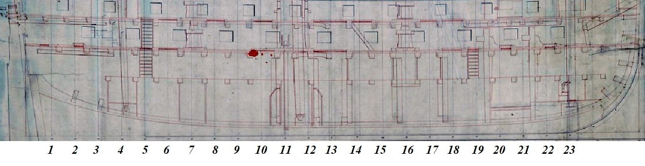
-
In the plans/drawings (which aren't very many) I have for HMS Leopard there is only one 'mention' of riders. Here's that 'mention' >>> In none of the plans/drawings of any 50 gun ship that I've found on the internet is there any help with the number and locations of these internal hull riders. So, what I'm asking is - - what would be the number, and approximate locations of the riders? Particularly in the area of the main mast? I'm considering doing a cross-section at a future date but would need a little more detailed info than already exists on the plans.
-
Thanks for your comment, Steven.
-
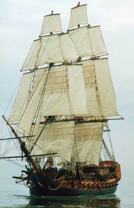
Thanks svein.erik for your comment. Just wanted to see Leopard out on the water so I played around in a very basic editing program I have. (I don't have anything proper like Photoshop.) You'll have to ignore the background above the waterline >>> And here's an RC model of Leopard under full sail out on the water >>>

-
Thanks to GrandpaPhil, Paul and Richard for your comments and again to the others for the many likes.
-
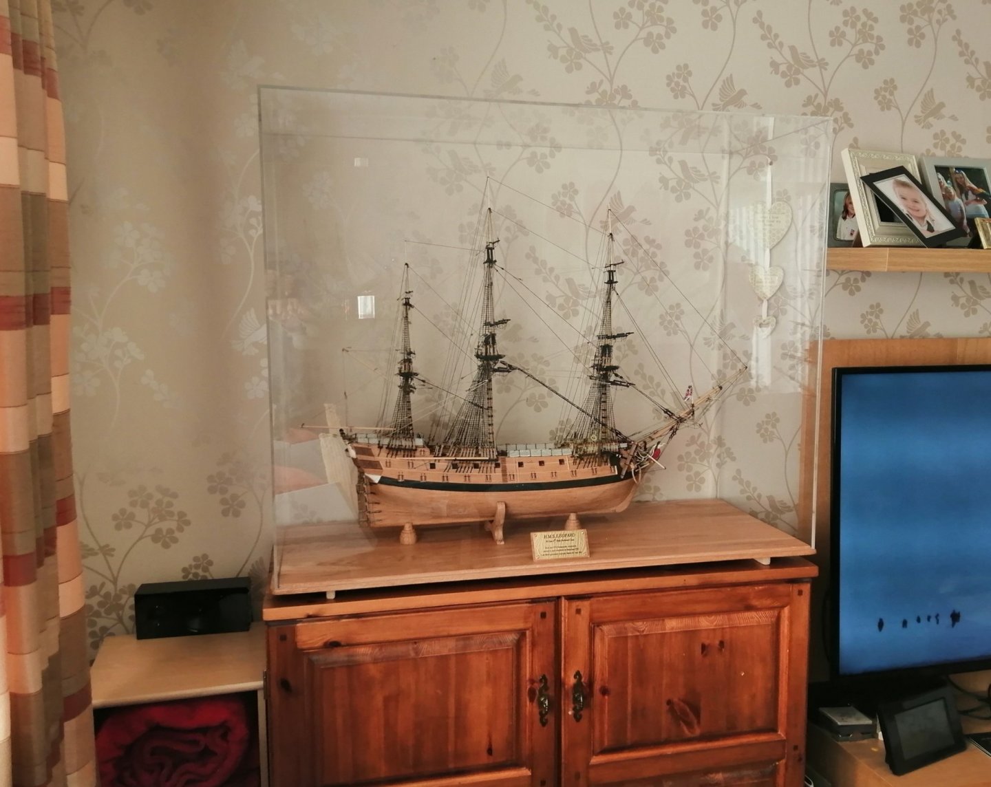
Thanks to Chris (Watton), Chris (Coyle), Tom, Mark, Christian, Paul and Denis for the comments and the others for the likes. Paul, I got the case at a place on the south coast just near Brighton. The company is called Striking Displays. This link will take you directly to their custom/bespoke page where you can input the dimensions of the case you want and you'll get an instant price (not including VAT.) https://www.strikingdisplays.co.uk/display-cases/custom-display-cases/custom-sized-display-case.html#DETAILS If it's for your Frigate 'Sirius' at a scale of 1:48 that would be a much bigger case than I got and I don't know if they have a maximum size at which they limit their cases - but it won't hurt to try. It costs over £60 for delivery as it comes on a pallet in a truck but you may be close enough to collect it yourself (if it would fit in your vehicle!). Denis ~ as far as I was able, I was following Peterssen's rigging guide and that shows the mizzen topsail and topgallant braces running to the taffrail. I felt that was going to be a bit busy there so I ran them as shown in one of my previous posts. The mizzen crossjack braces are run to the pinrails on each side of the Q/deck via blocks on the aftmost mainmast shrouds.
-
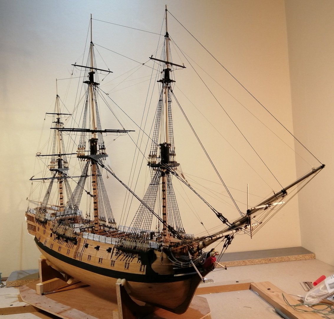
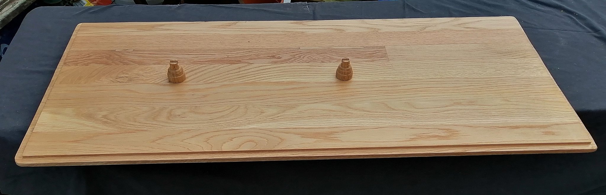
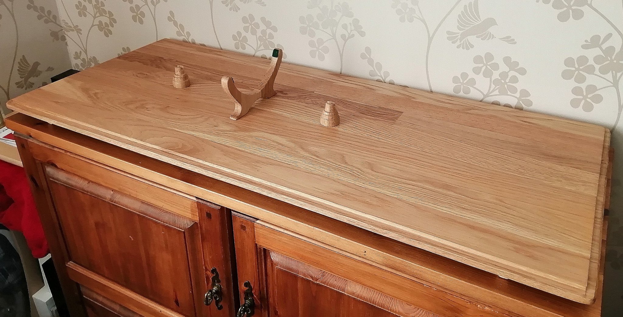
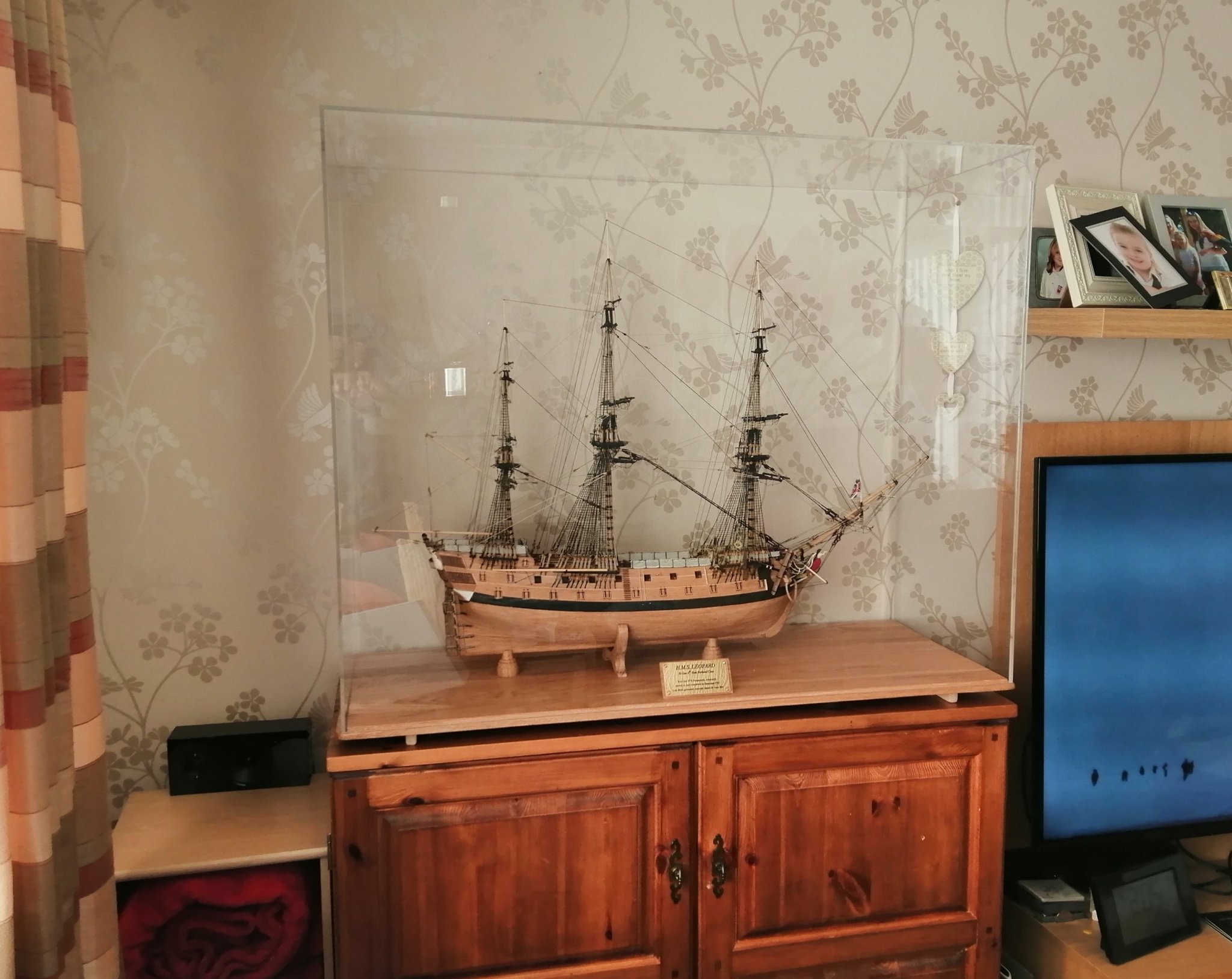
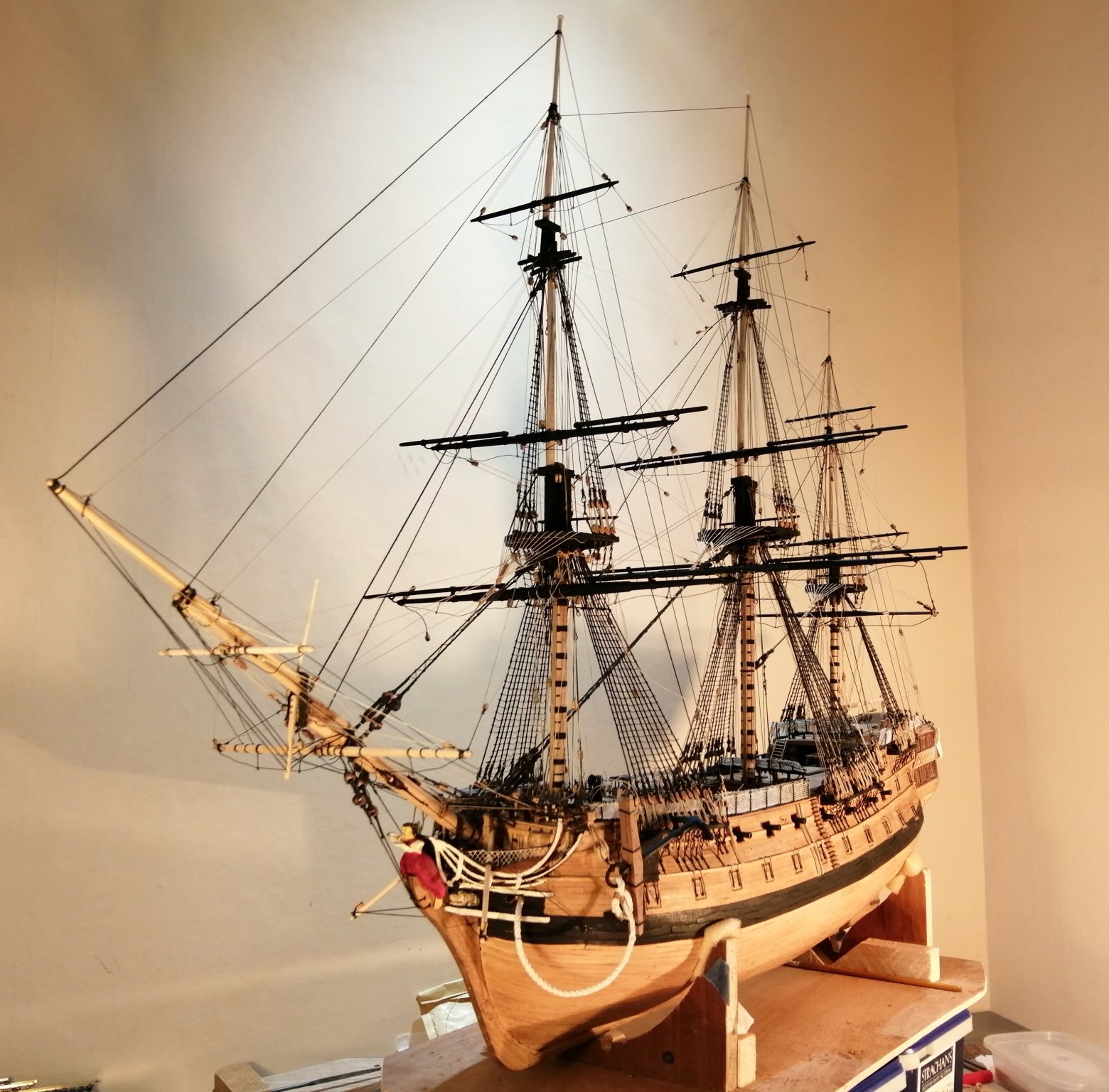
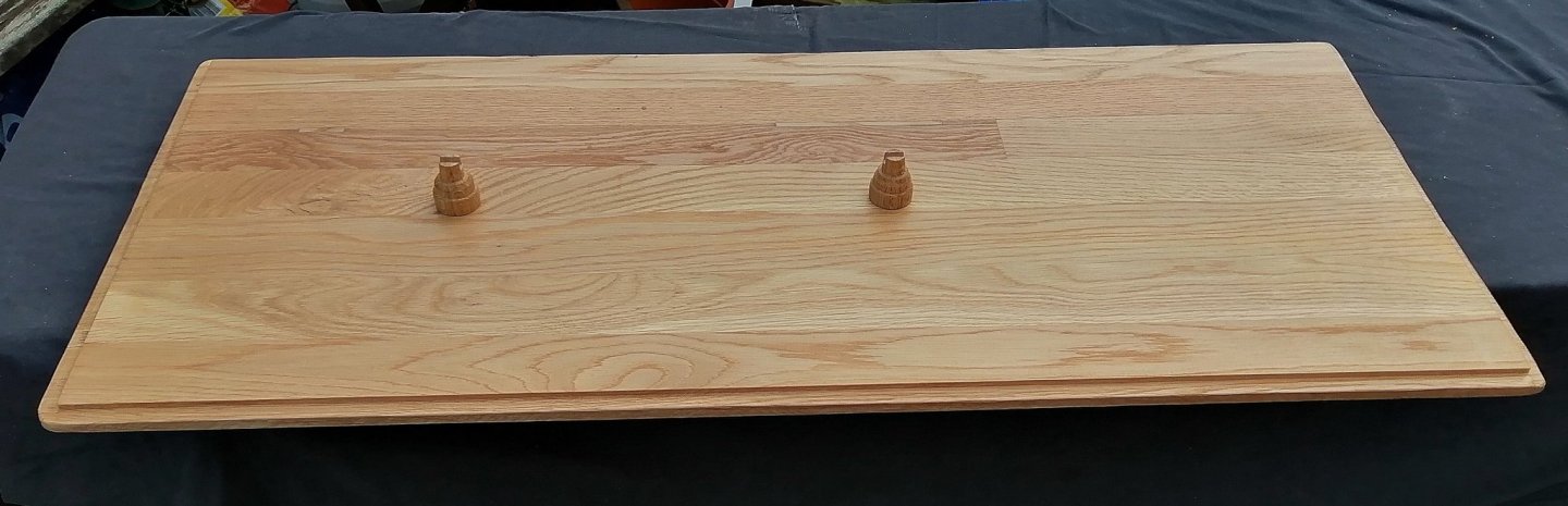
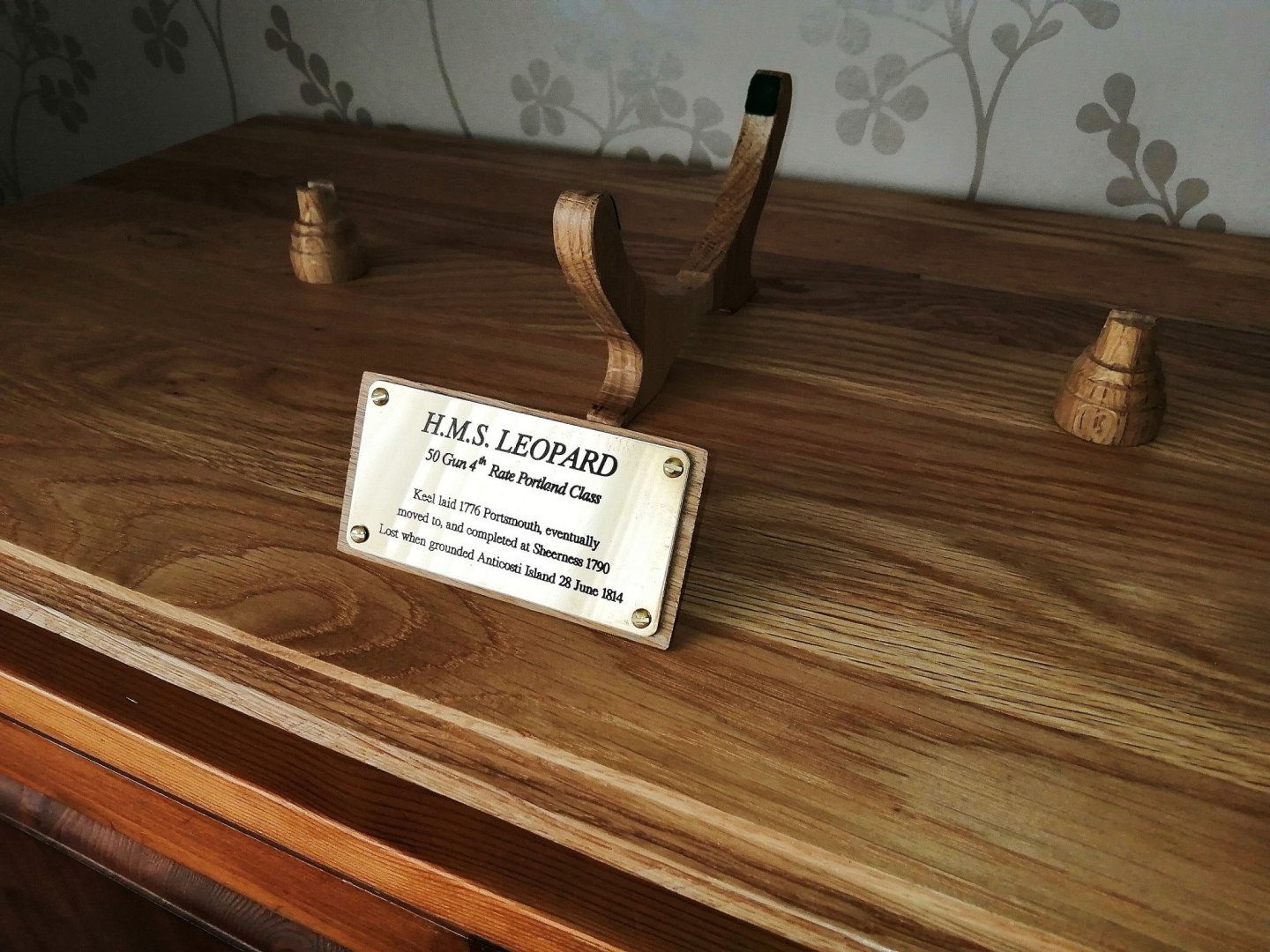
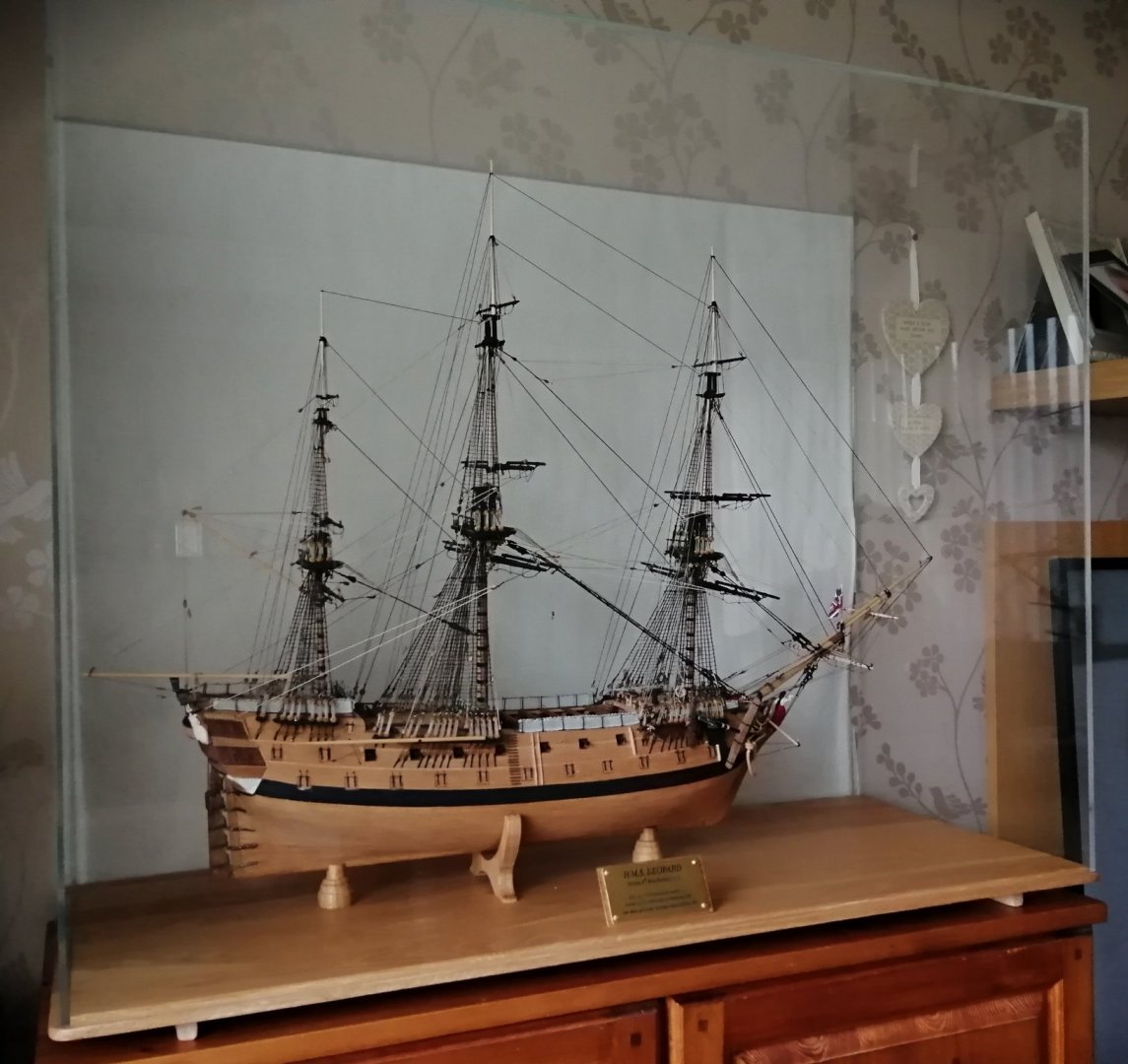
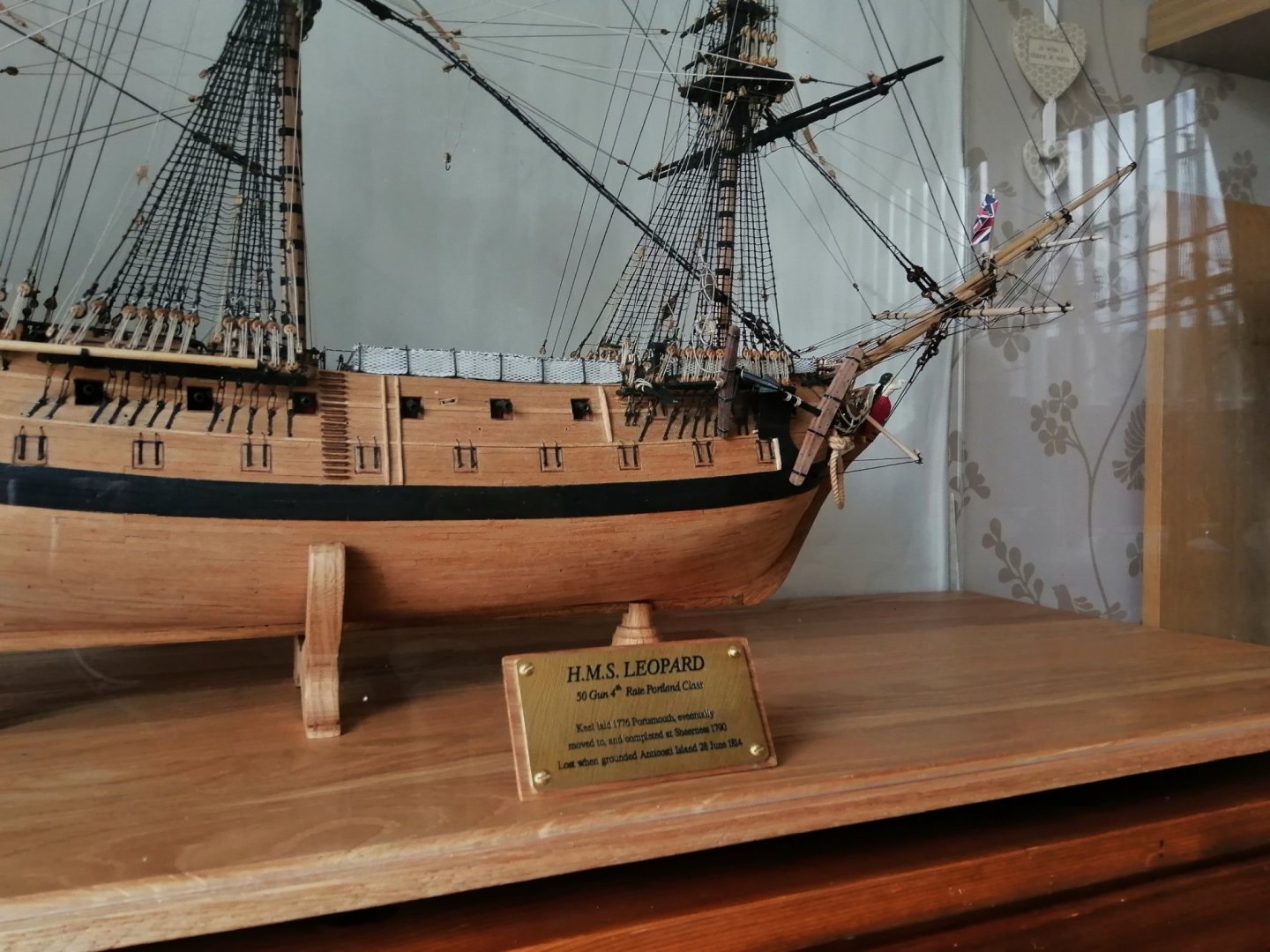
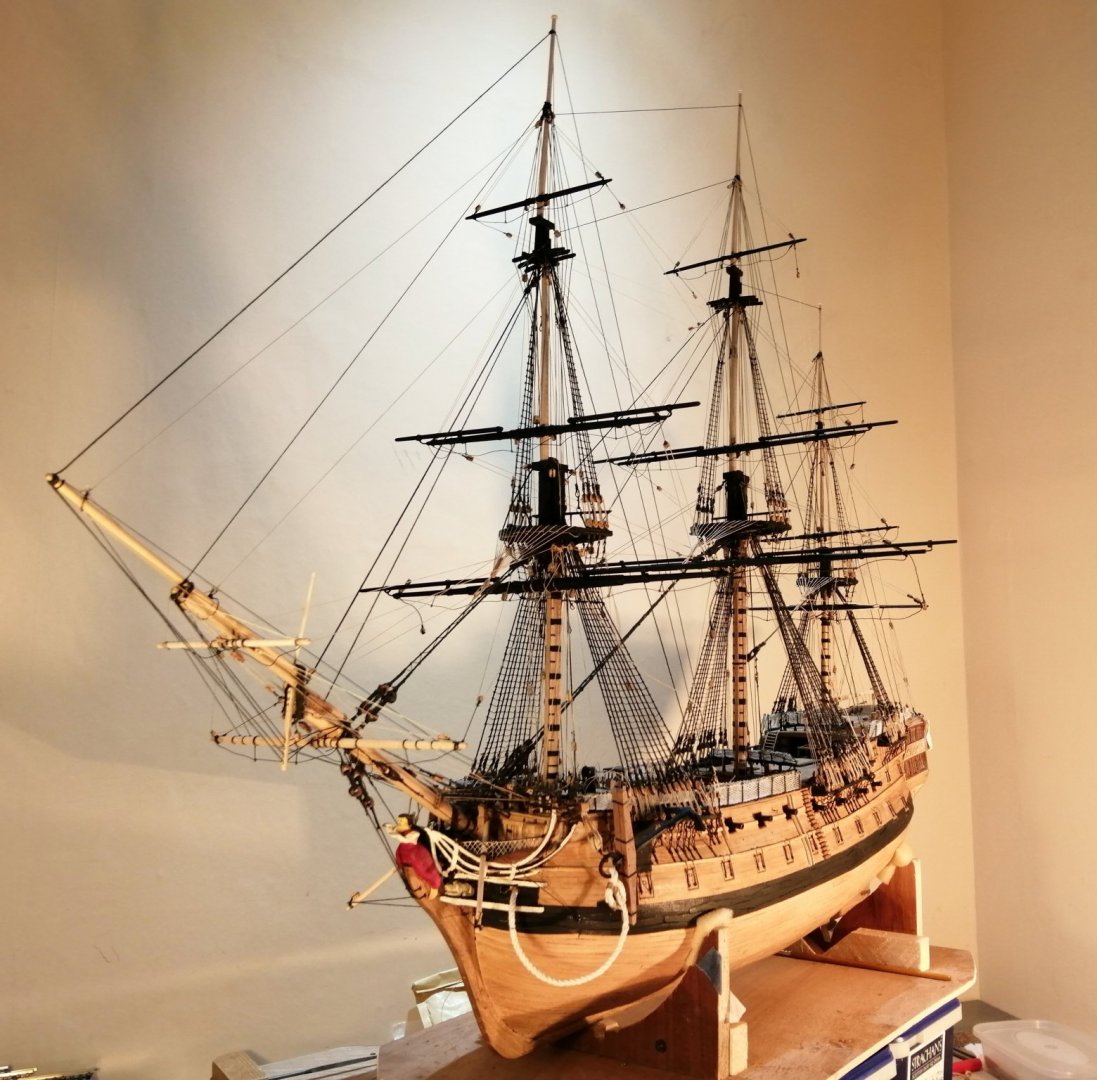
Just over nine years and it's now finished ~ well, I still have to make the boats, but for her own safety, Leopard will be going in her case as it will take some time to figure how on earth I'm even going to make a start on the boats. A couple of months back I took some time out to fashion a base and supports for the ship. Here's the base with two pedestals > Last year my neighbour was renewing her kitchen and was throwing out her 'old' cabinets and doors. The doors were solid oak ~ not just the frames, but the raised panels as well. Throwing out OAK - - - that should be a criminal offence!!! (With her permission) I saved the lot and have made a few projects and also still have several of the doors 'in reserve'. The oak board in the photo above was made from that saved timber as were the two turned pedestals. The pedestals alone won't support the ship as there is no provision inside the keel to make the ship vertically secure, so there is a central 'cradle' (also made from the oak) that will keep the ship on 'an even keel'. >>> e I routed a rebate (American - rabbet) all round the base so that the acrylic case will be 'anchored' and won't be able to slide around. The case has been the most expensive single item in relation to the entire build. I had considered obtaining acrylic sheets and making my own case but the amount of work involved in making a wooden frame guided me to the easier route of purchasing a commercially made item. I also got a commercially engraved brass plaque >>> (The brass plate is mounted on oak from my neighbour's kitchen!} And now, Leopard finds refuge away from the danger of a clumsy ship builder's hands and elbows as well as from the exploring hands of his grandchildren! Although I stated that it's been over nine years in the making, it's probably closer to six years as there have been a few considerably long lay-off periods.

- 257 replies
-
- 21
-

-

-
Hi Matrim, I can't really compare this scale with anything else as this is the first build I've done (I've never even built a ship from a kit before,) but at times it certainly was a bit fiddly ~ especially areas like the stern quarters. The plans that came with the book were at 1:96 but I felt that was going to be too tight for me and as much as I would have preferred a scale of 1:64 or bigger, display space would have been a problem so I struck a 'mid-way' compromise of 1:80. As it is, at this scale, it now measures (overall length) 960mm X 760mm (keel to truck). The case I ordered is 1020mm long by 810mm high.
-
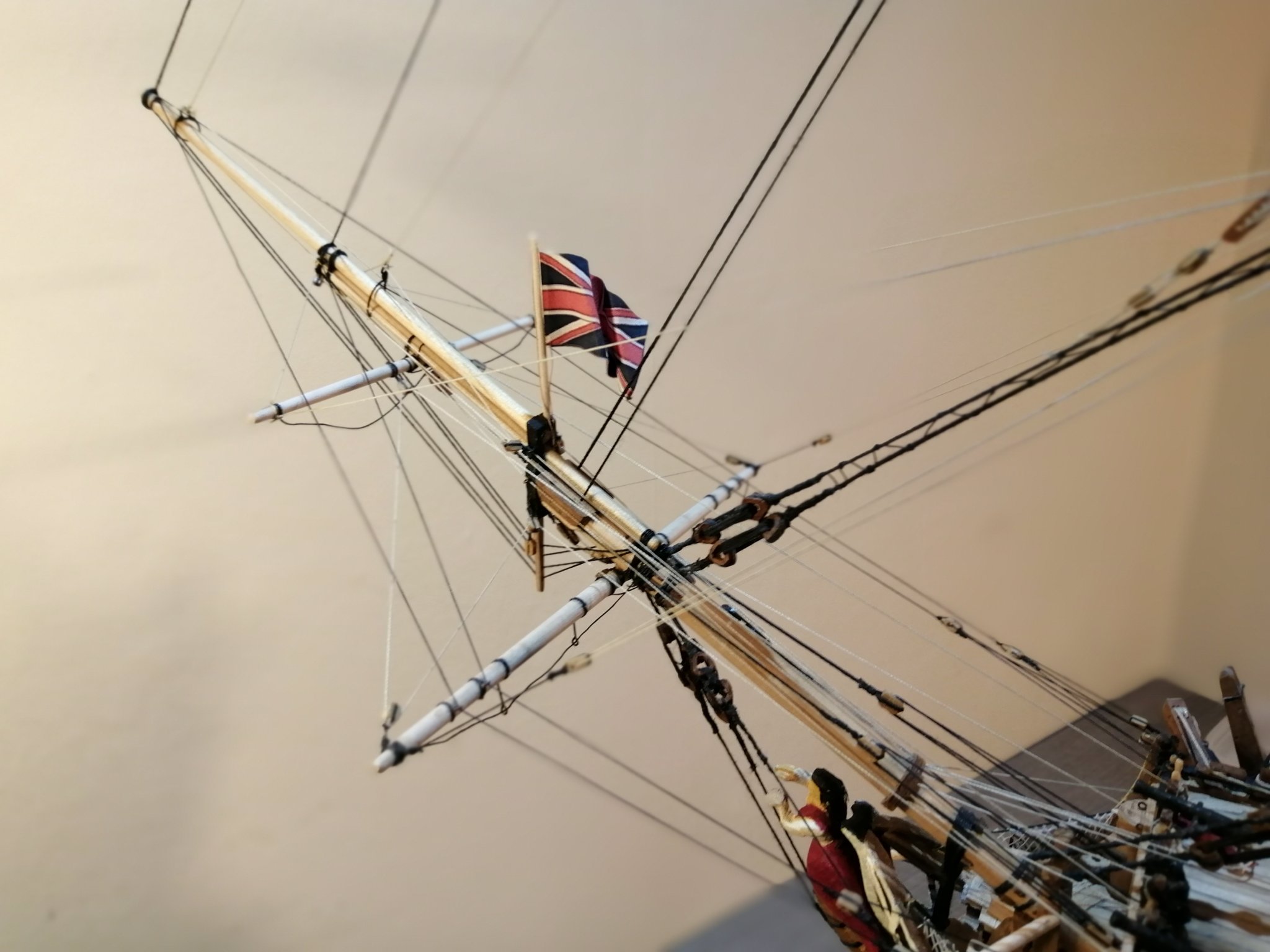
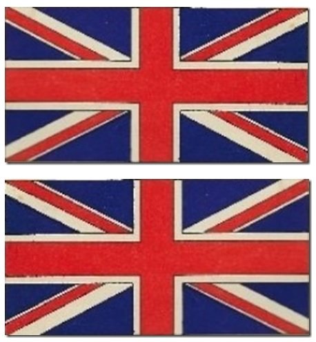
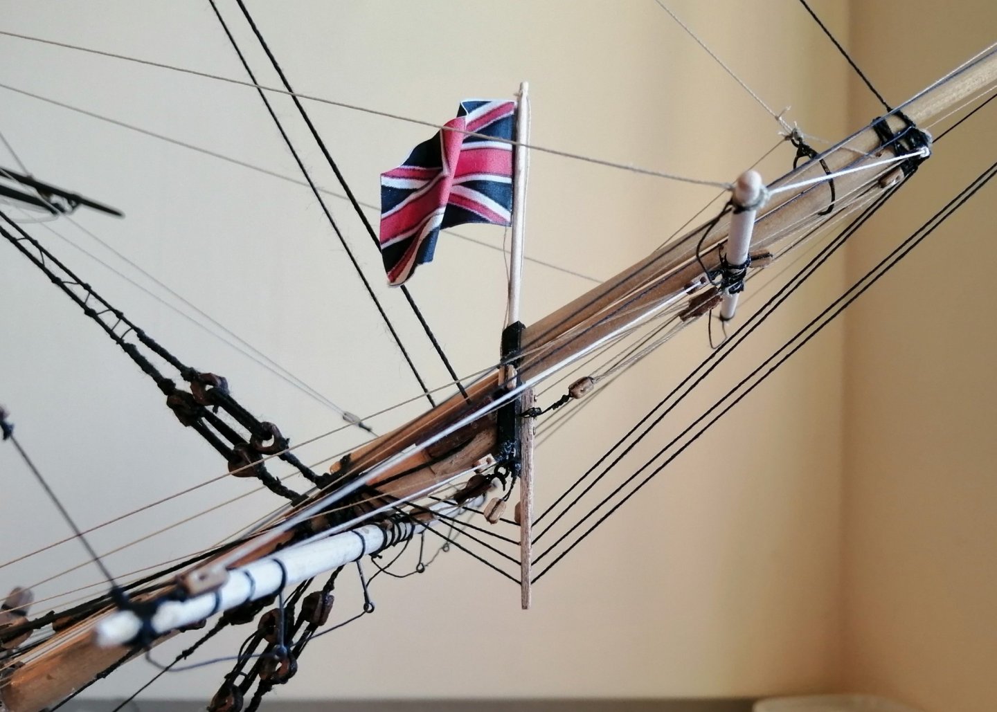
Hi Paul, Yes, I was aware of the dates and the correct flag for 1790, but I kind of argued with myself that as the ship survived until 1814 then either flag would probably have been OK ! (at least within the right time period.) (The correct 1790 flag would have been easier as I wouldn't have had to have it flipped and it couldn't have been displayed upside down either ) I'm sure there are (in fact I KNOW there are!) a few more "slightly less than accurate" features on the ship so I'm not unduly worried about the flag!
-
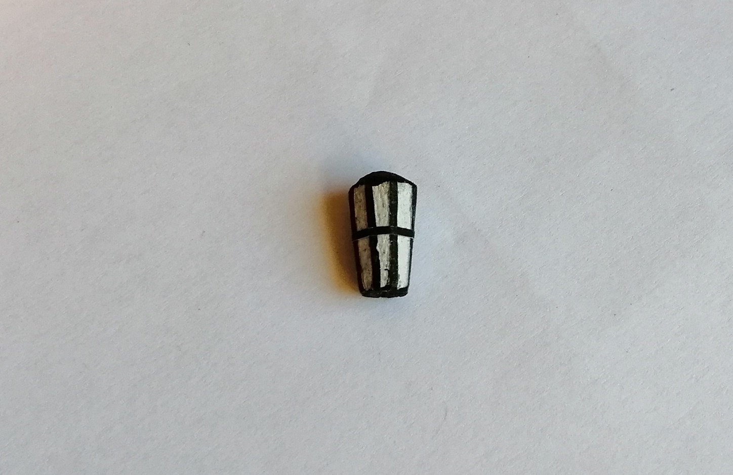
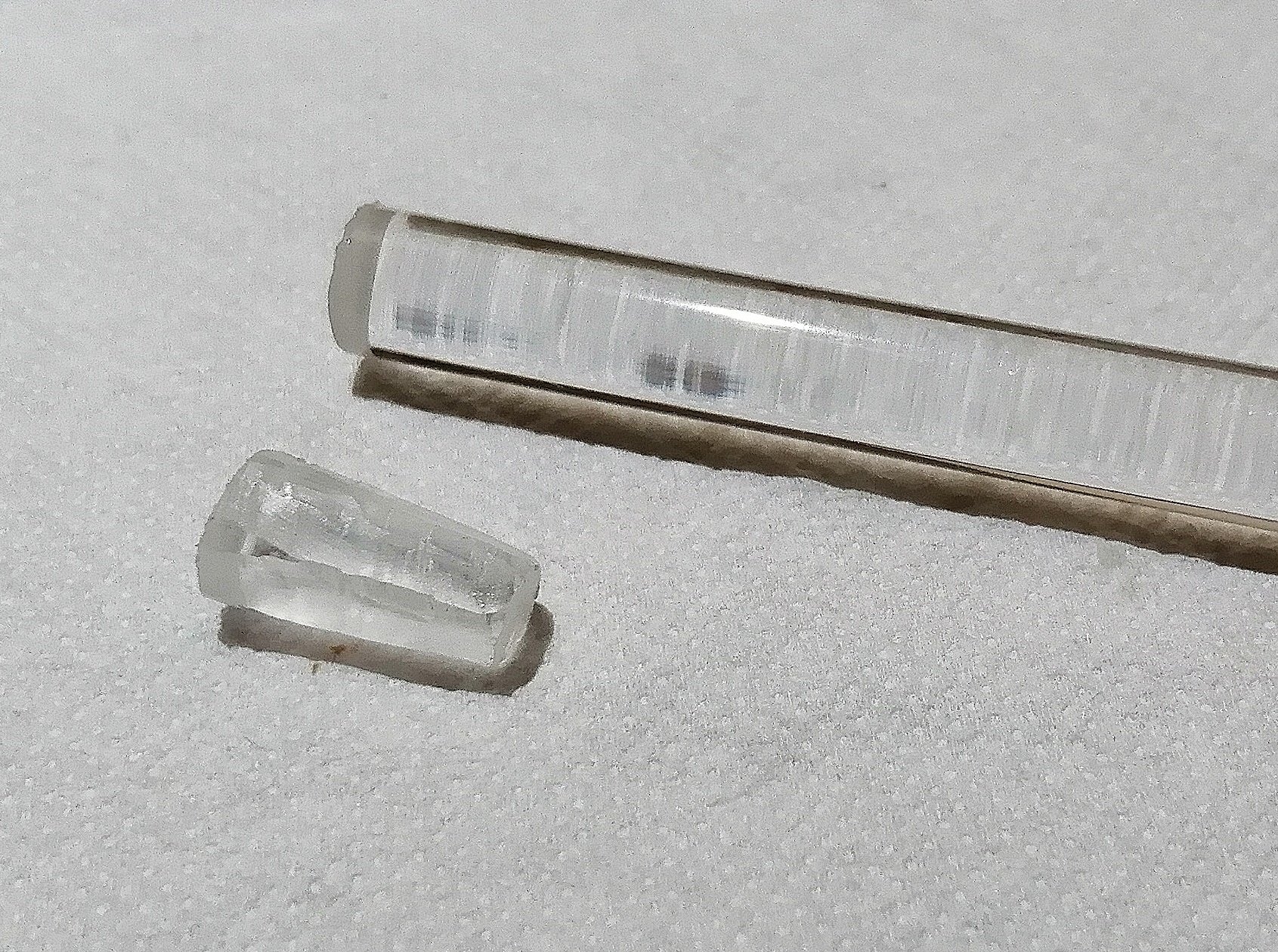
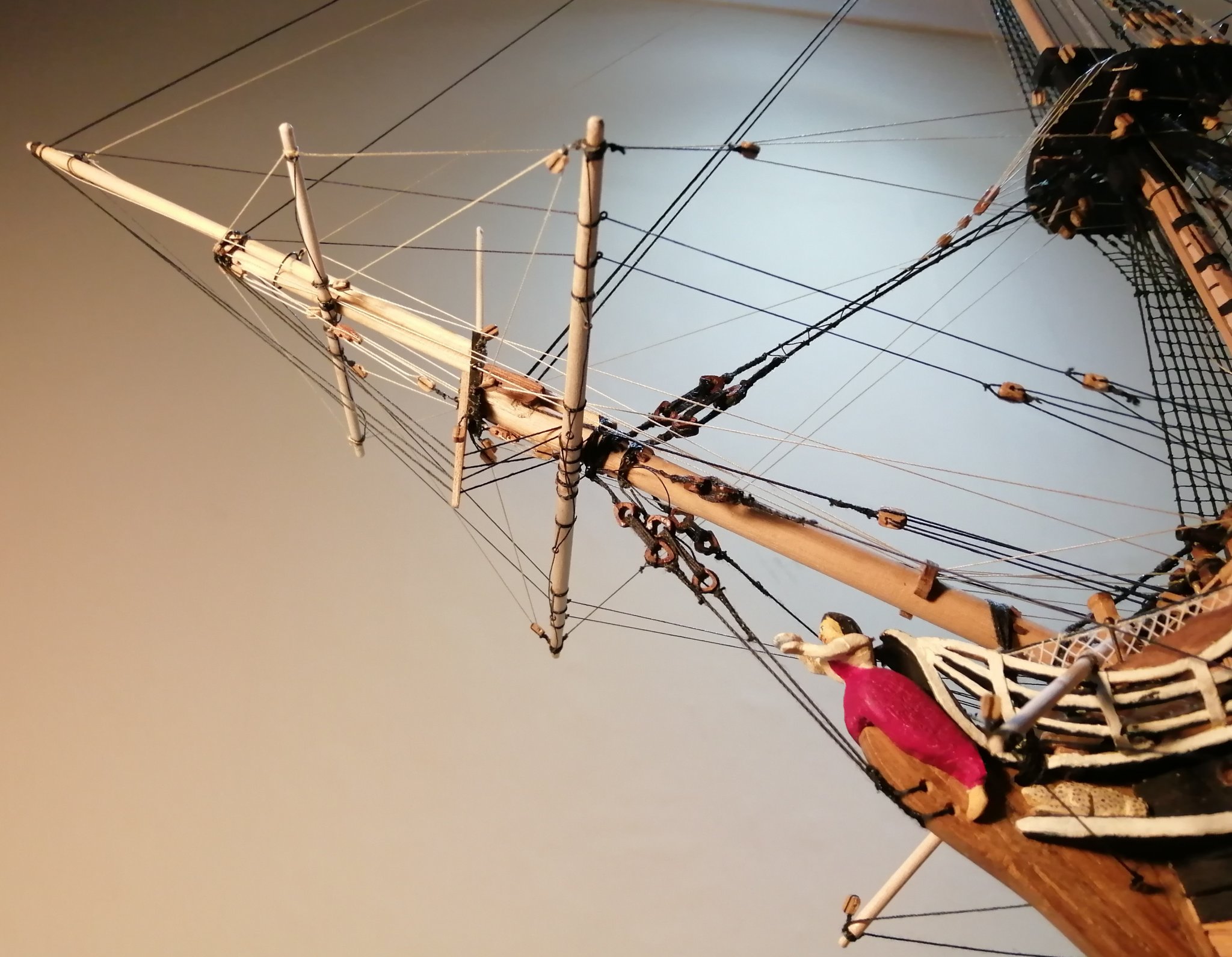
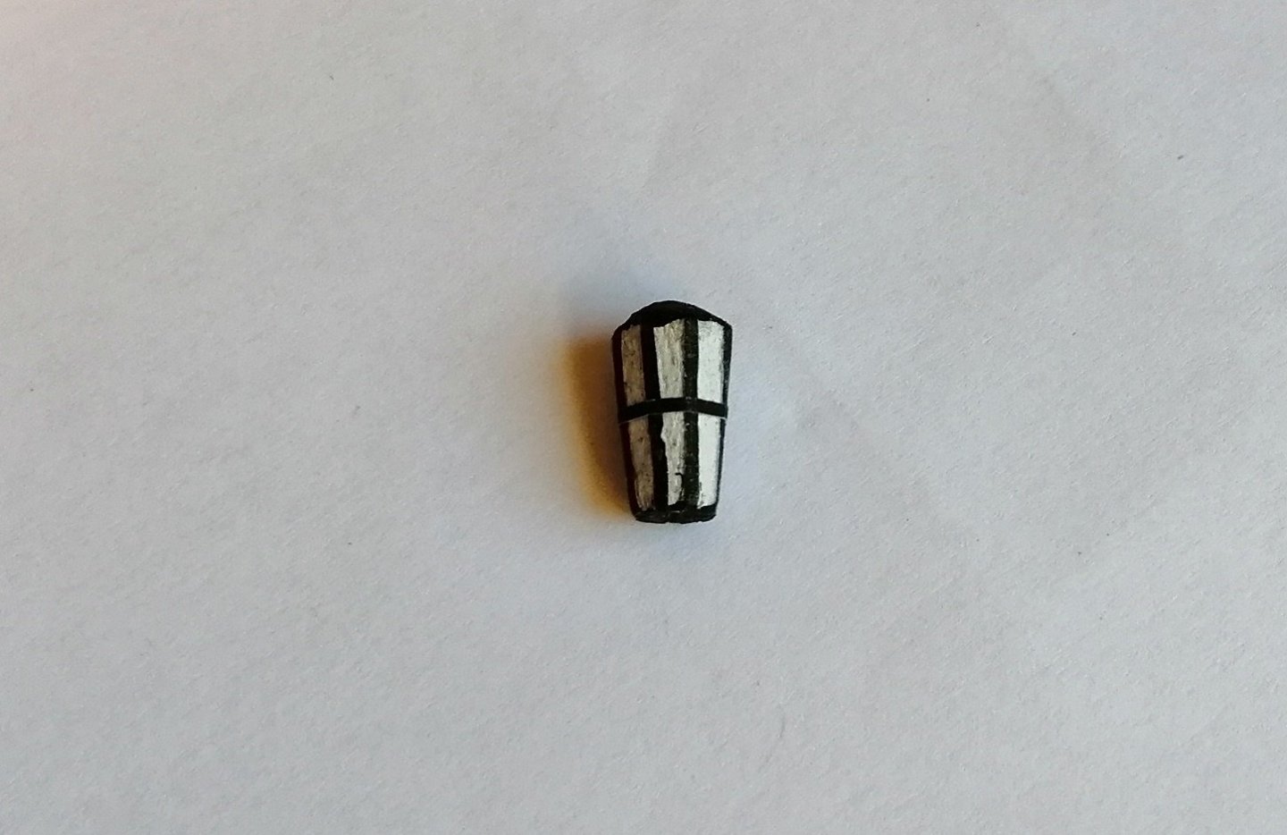
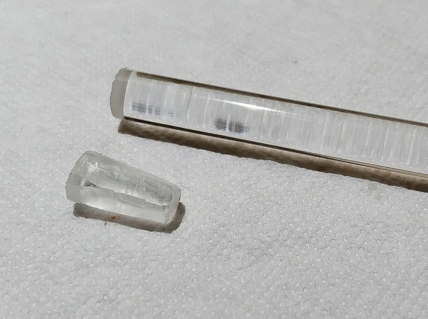
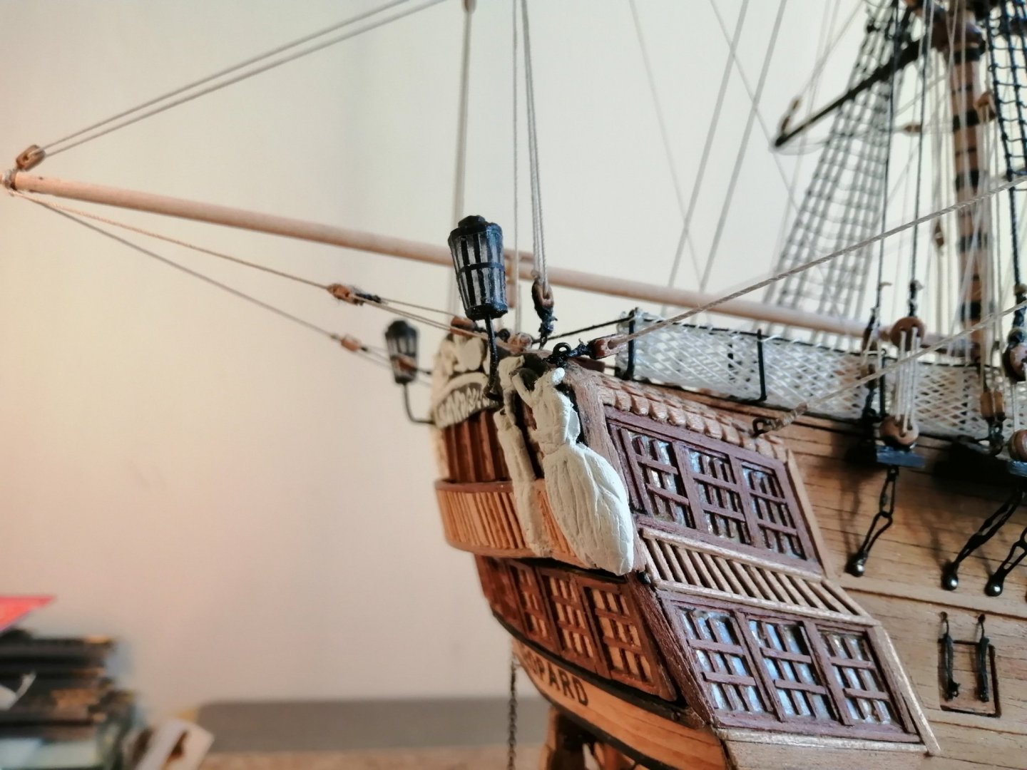
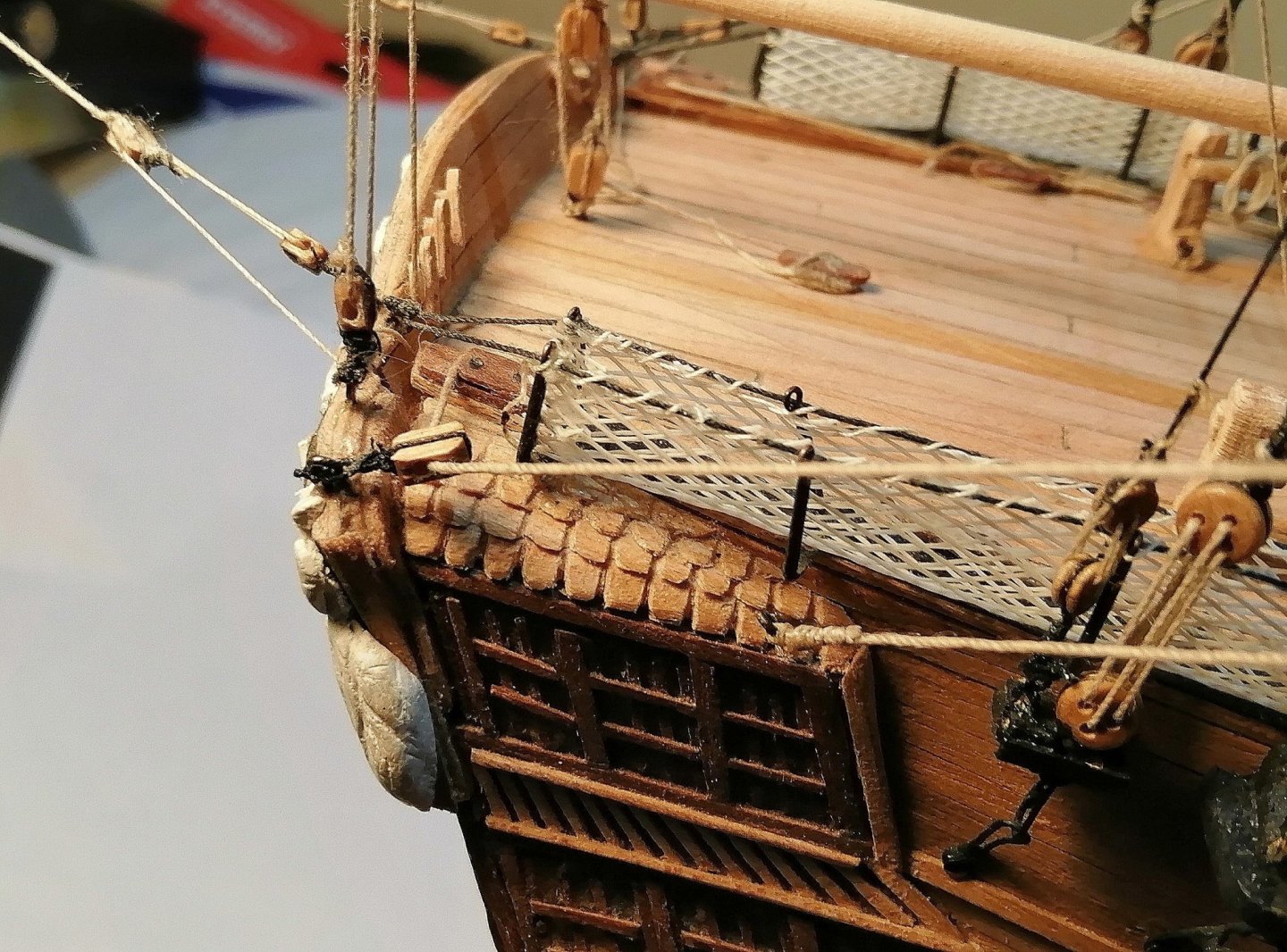
Small tasks are now almost done. Stern lanterns: My first attempts at this project involved trying to solder pieces of 0.5mm brass wire into window frames for the lanterns but that venture was pretty dismal. I then had a go at whittling an 8mm dowel down into an 8 sided shape tapering down to about 5mm at the 'thin end' and ended up with this >>> I didn't like the white painted "glass" and hoped to be able to get a more transparent look. I bought an 8mm clear Perspex rod and used a chisel to whittle it down to a tapering hexagon shape and decided to go with that. (These brutal close-ups make everything appear much worse than they are in reality! Even the unused section of rod in the photo below, despite being perfectly crystal clear, looks second hand here.) >>> And on the ship >>> The window 'frames' are black paper cut into strips of 0.5mm widths. I almost forgot the bowsprit Jack. I had an image of a Jack in my gallery and used a free website to flip the image horizontally and both images are seen in the pic below >>> I printed them, cut them out, glued them back to back and crinkled them to resemble a fluttering shape >>>

-
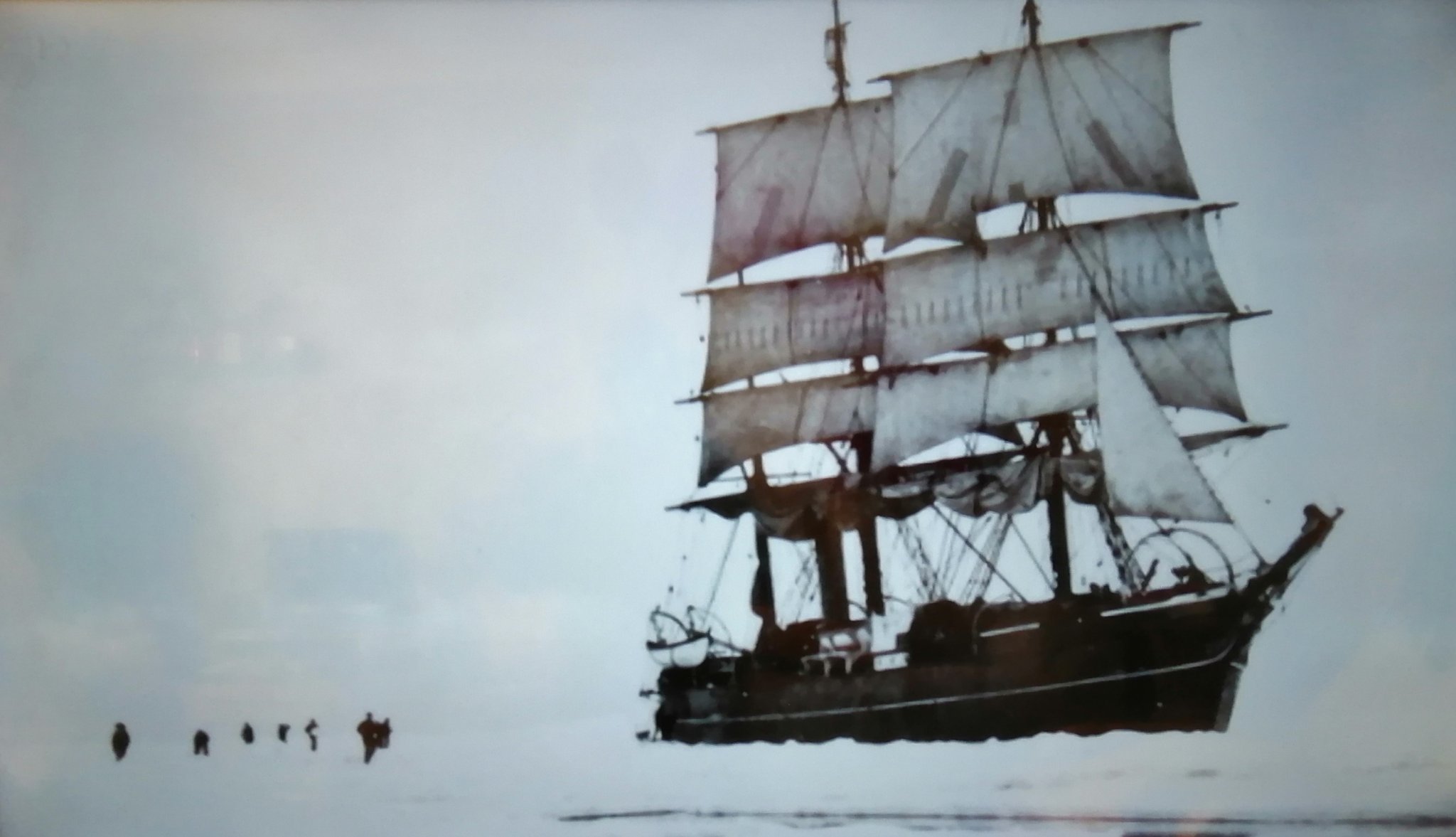
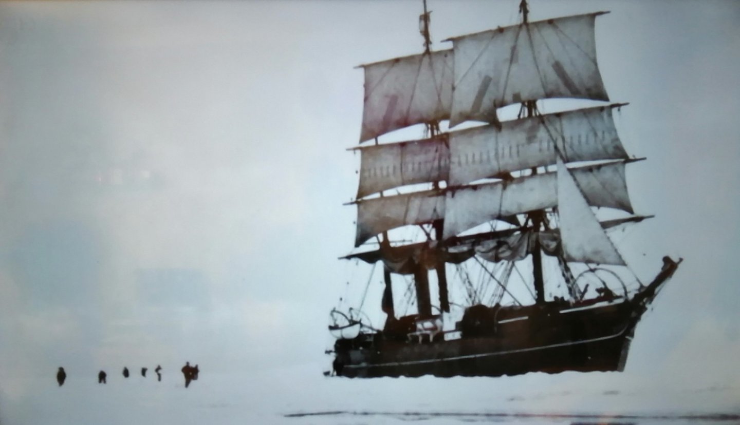
Was watching a documentary about Scott's Antarctic expedition (1901 - 1904) and was a bit puzzled by one of the still shots. Maybe I'm missing something, or maybe there's something obvious I'm not seeing. It's a photo of the ship when it was 'docked' in the ice. (It was there for a l-o-n-g time.) In the photo several of the men are out on the ice and Discovery is shown, with the exception of the lower sails being brailed, almost under full sail. What would be the reason for all that canvas while being "in dock"? Here's the photo >>>
-
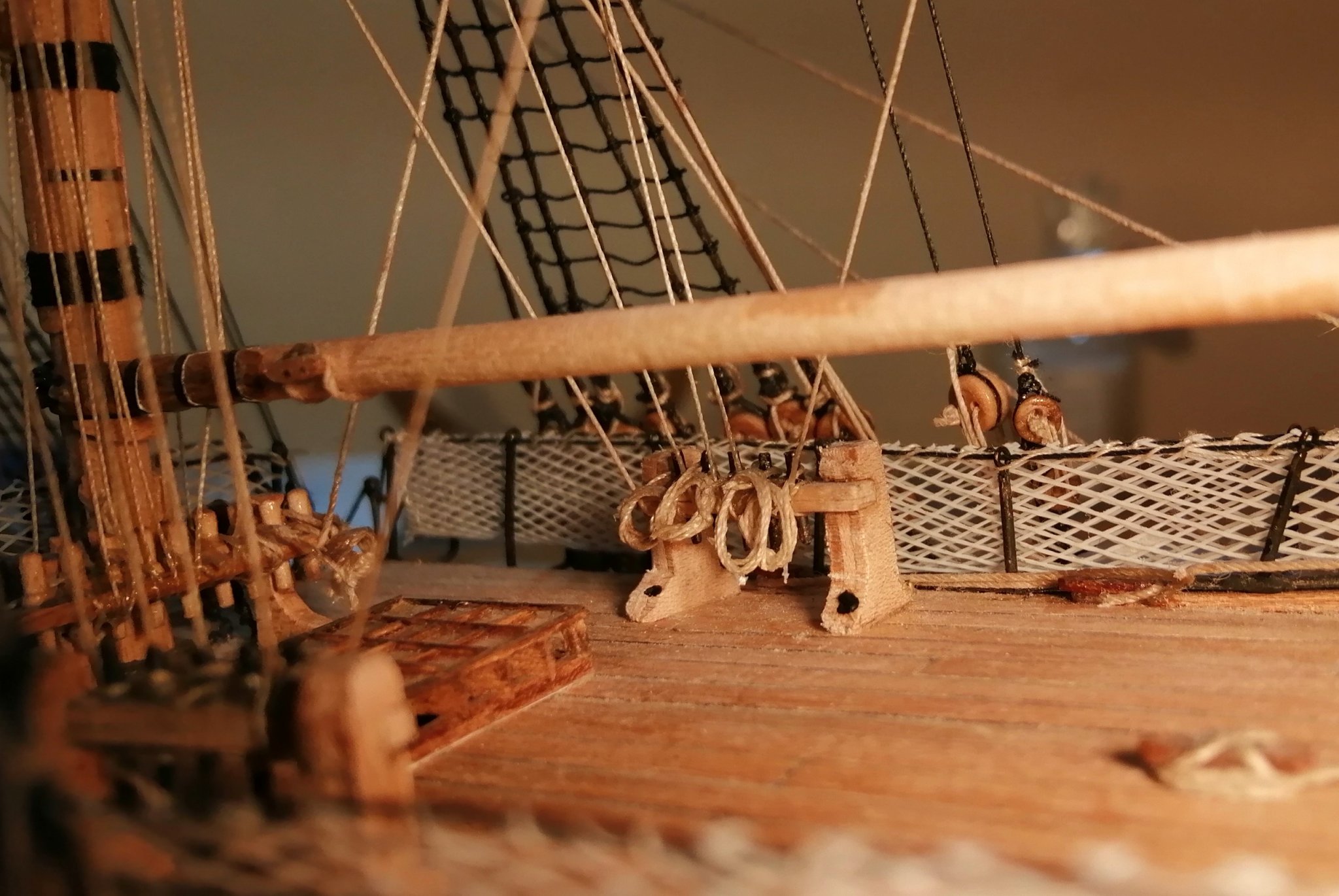
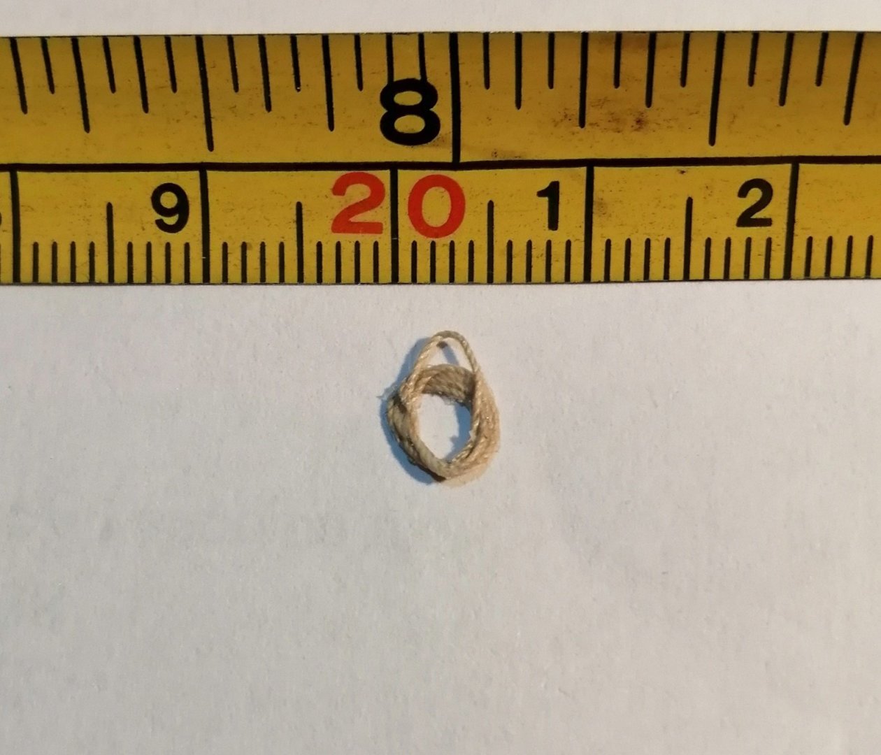
Slowly getting on with the rope coils while at the same time trying to get something to work that may be acceptable as stern lanterns. I don't loop the coils directly over the pins but instead loop over just a single 'strand' of the 'rope'. Back in 2003 when I sailed on H M B Endeavour we were shown how to attach the final loops to the pins. I'll link a video which shows the 'normal' way to attach the loops. Here is one of the loops I make showing a single 'strand' above the loop which I hang over the pin >>> The video is over 6 minutes long but the relevant part is just a short part between 2 mins 12 seconds and 2 mins 25 seconds. Here's the video >>>
-
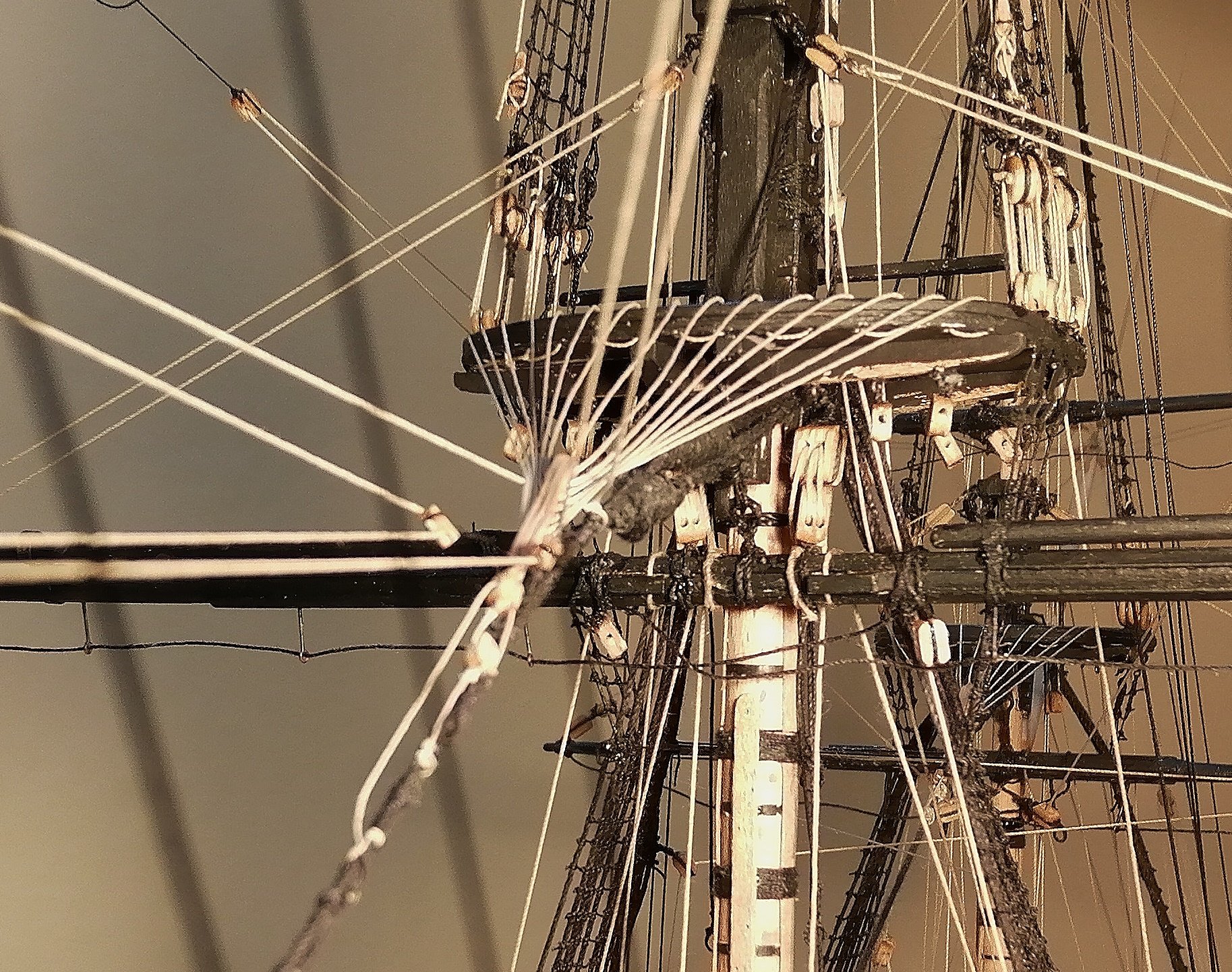
Hi Tom, That ship is really looking the part now! I can see you've been busy - - - I know how long it takes just to get one mast section prepared. You're right about getting the blocks fitted to the underside of the tops before permanently fixing them to the masts . . . and don't forget to fit a block in the centre at the aft end of the fore and main tops which the nave lines will need later. I forgot, and when I came to fit them 'in situ' I wished I had done them at the stage you're at now! Better to have a few unused blocks hanging there than to be lacking a few when they're needed.
-
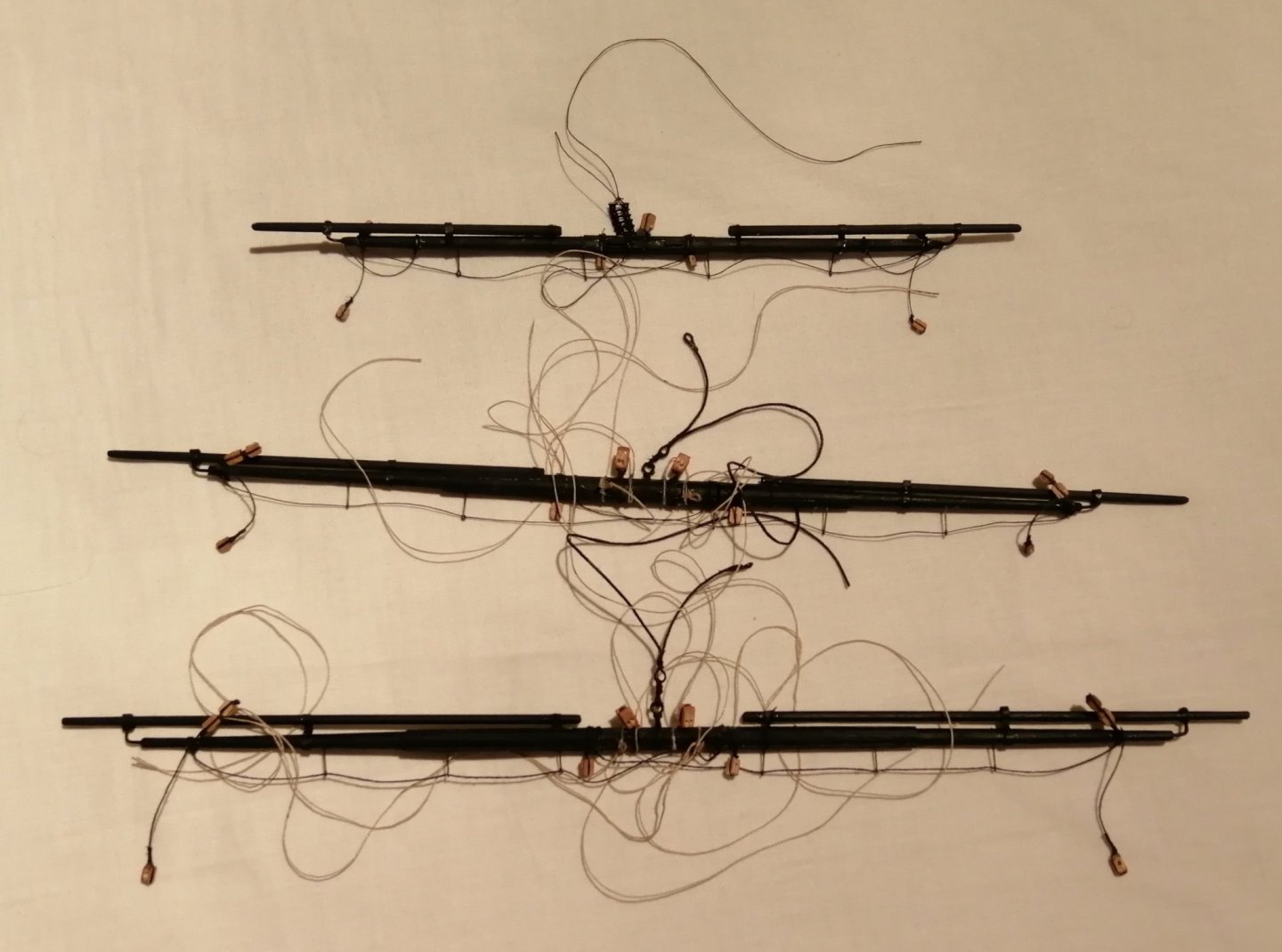
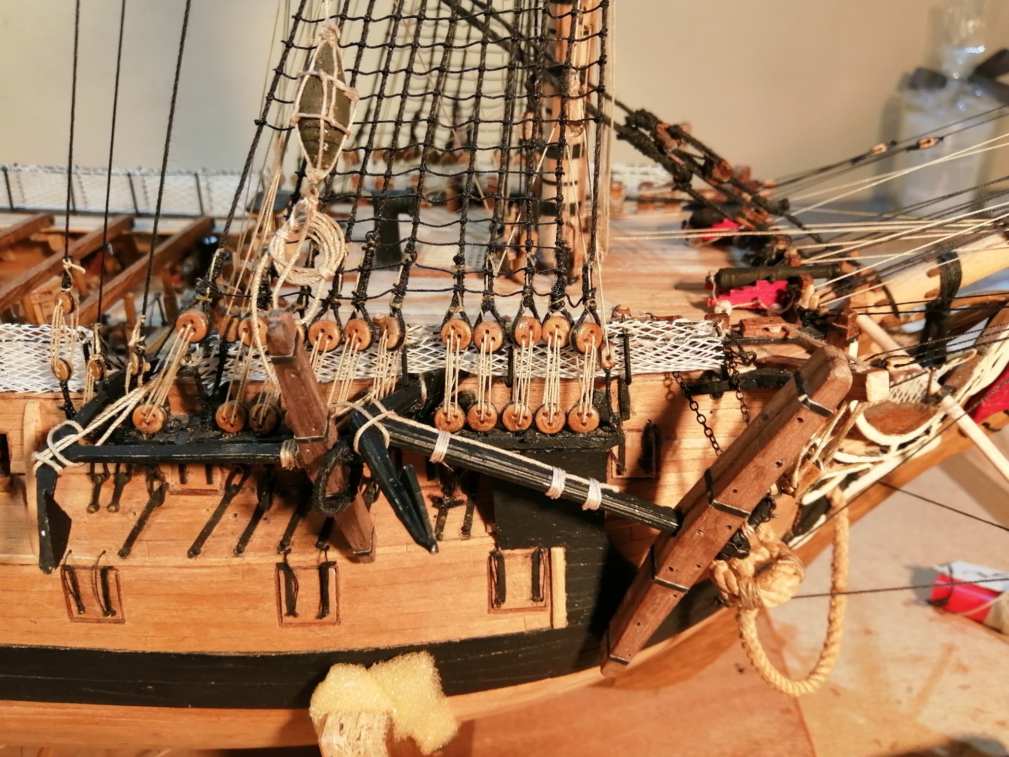
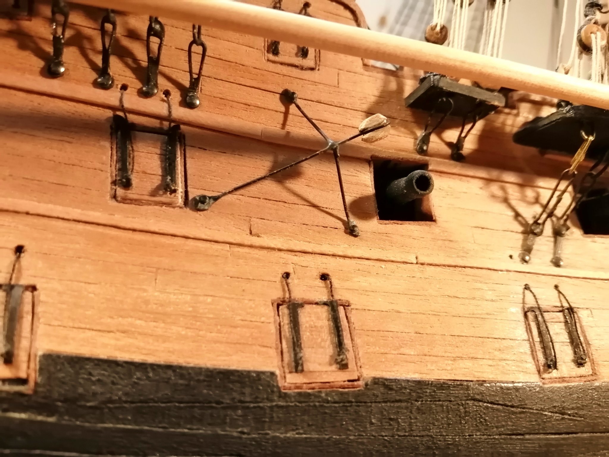
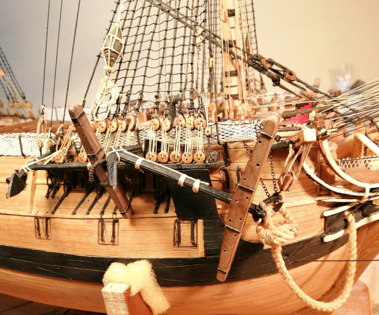
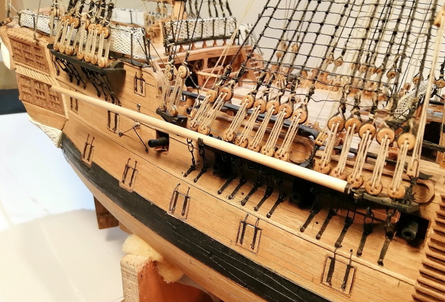
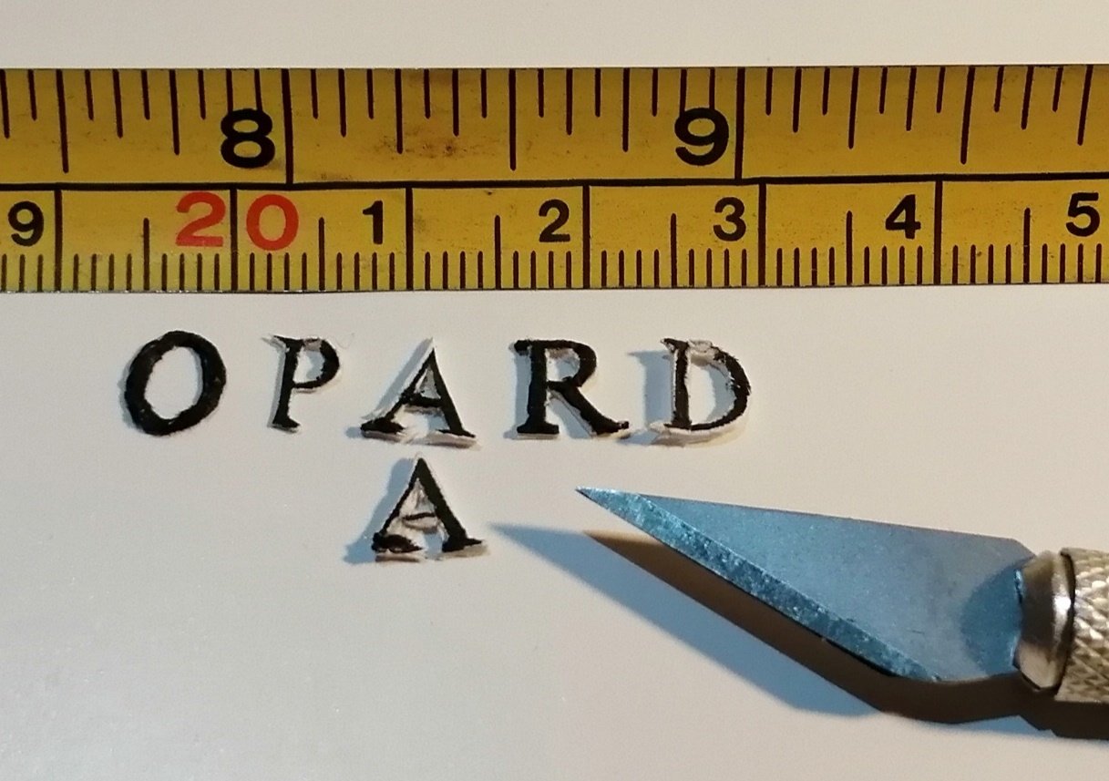
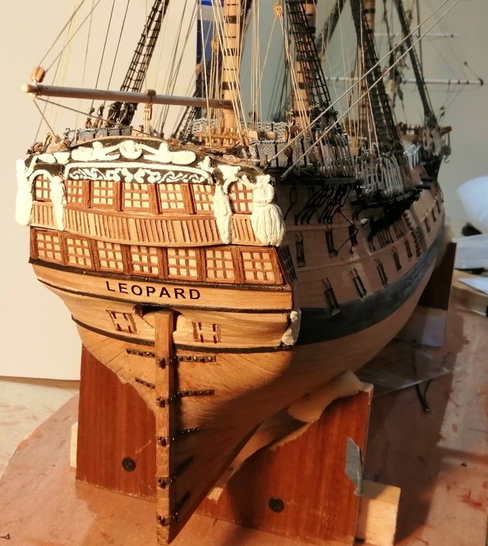
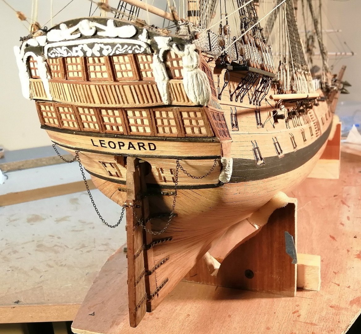
Although it's a few weeks since the last of the rigging was done, Leopard's keel is still not about to rest on its proper base yet. There have been several small peripheral jobs to be done and although they're 'small', they're 'big' in terms of the time it is taking to get them done! Finally have the anchors prepared and ready. One particular item (well, two of the same) that has been particularly challenging to rig has been the anchor buoys. They have been equally as challenging and frustrating as any other aspect of the rigging on the entire ship - - - but they're done now . . . YAY! Creating the basic buoys was fairly easy . . . their rigging was something else >>> The plans I have show nothing of how the anchors were stowed and my knowledge of this is limited to what I have seen of other modellers stowage of their anchors. There appears to be no 'standard' method of stowing and lashing anchors so I have done what fits best around and along the fore channels on both sides. A couple of blocks are mounted in 'stand-off' metal brackets and are attached, one each side, to the hull between the main and mizzen masts. I'm sure they'll have a proper nautical name but I don't know what it is. I believe these blocks are used in the running rigging and are associated with the fore course sail. Here's the one on the starboard side >>> The main lower stunsail yards were a welcome uncomplicated venture for a change! Here's the starboard side >>> Up to this point (after 9 years) this ship has had no real identity. It was time to change that. I really wanted to create the lettering myself . . . and I DID try, but when I tried to cut these tiny 5mm letters out the results were pretty appalling. When you see them you'll understand why they weren't going near the ship! I opted to buy a sheet of self adhesive vinyl letters >>> The rudder was a project I made several years back and it's been in 'the box' since. With its pendants >>> A small detail, but there are so many of them are the coils for looping over the belaying pins . . . AND they're very frustrating trying to get them looped over (and to stay looped over!) when there are now so many lines making everything very congested. I've done around 20 of them and there must still be at least another 20. (I'm scared to count them!) As far as I'm aware, apart from these coils, there are just the stern lanterns to be done then Leopard can rest her keel in her proper base.


- 257 replies
-
- 11
-
-
Hi Tom, Just jumping in here to mention one other 'adjustment' I made to the rigging. A while back I noticed that a straight line from the main yard back to the snatch block for the main brace was going to collide with the aft end of the hammock cranes on the poop deck so I added an extra block on the outboard end of the taffrail at each side to ease the route of the main braces. See the photo. >>>
-
Hi Tom, I suspect you're working from the same plans as I have and you've probably also got Petersen's rigging book? As you know, the plans won't help you much with the rigging but the book was invaluable to me, although it's for a frigate and I still had to be a bit inventive with some belaying points as well as the routes some of the lines took to get 'home'. The poop deck behind the mizzen mast is woefully short of pins and I added 5 cleats to the mast as well as 2 pinrails each with 5 pins as you saw in an earlier post of mine. The quarterdeck behind the main is fairly well supplied with pins (according to the plans) but I also added 4 cleats to the mast down behind the jeer bitts although only 2 of them have been used. On the foredeck the plans only show the pinrails immediately ahead and abaft the foremast. I added 4 pins on each side of the belfry (8 in total) along the forecastle rail and all these pins are populated with lines. I also added 4 cleats to the foremast. Along the fiferail, again no pins shown on the plans but I added 8 (4 on each side) and these, along with all the timberheads there, are all fully subscribed, in fact I had to lead the 2 jib & flying jib inhaul lines back to the pinrail ahead of the mast. In addition to the above, I had to 're-invent the wheel' with the route and final positions of a few lines that I just couldn't get 'to fit' Petersen's rigging guide.
-
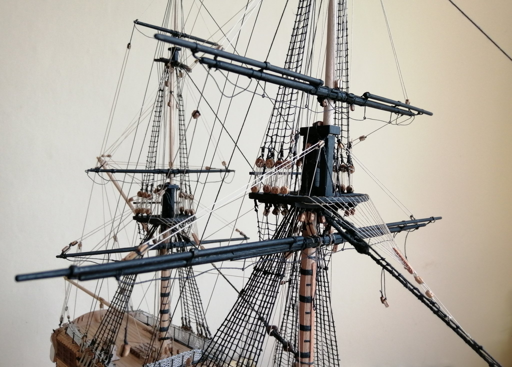
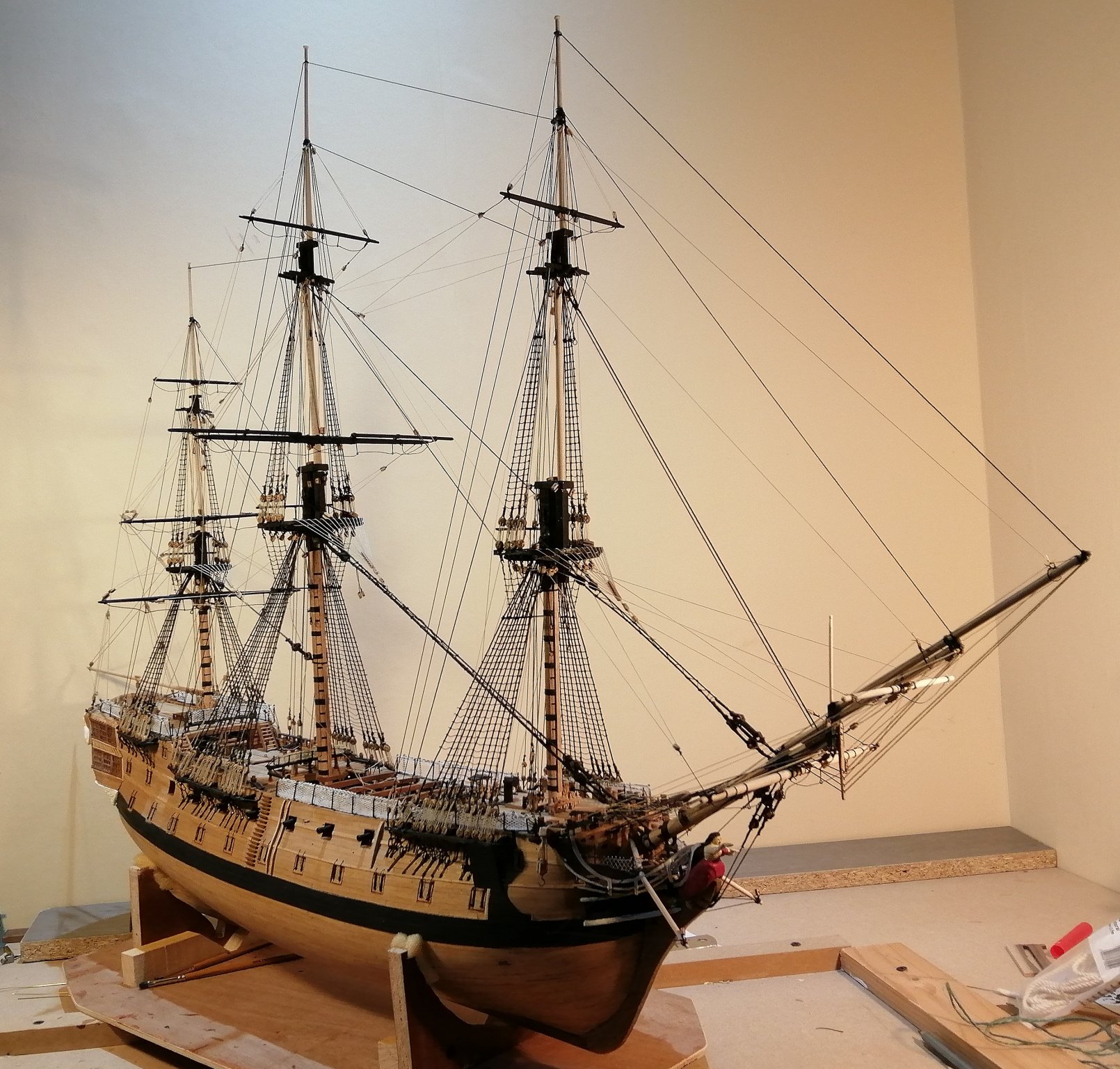
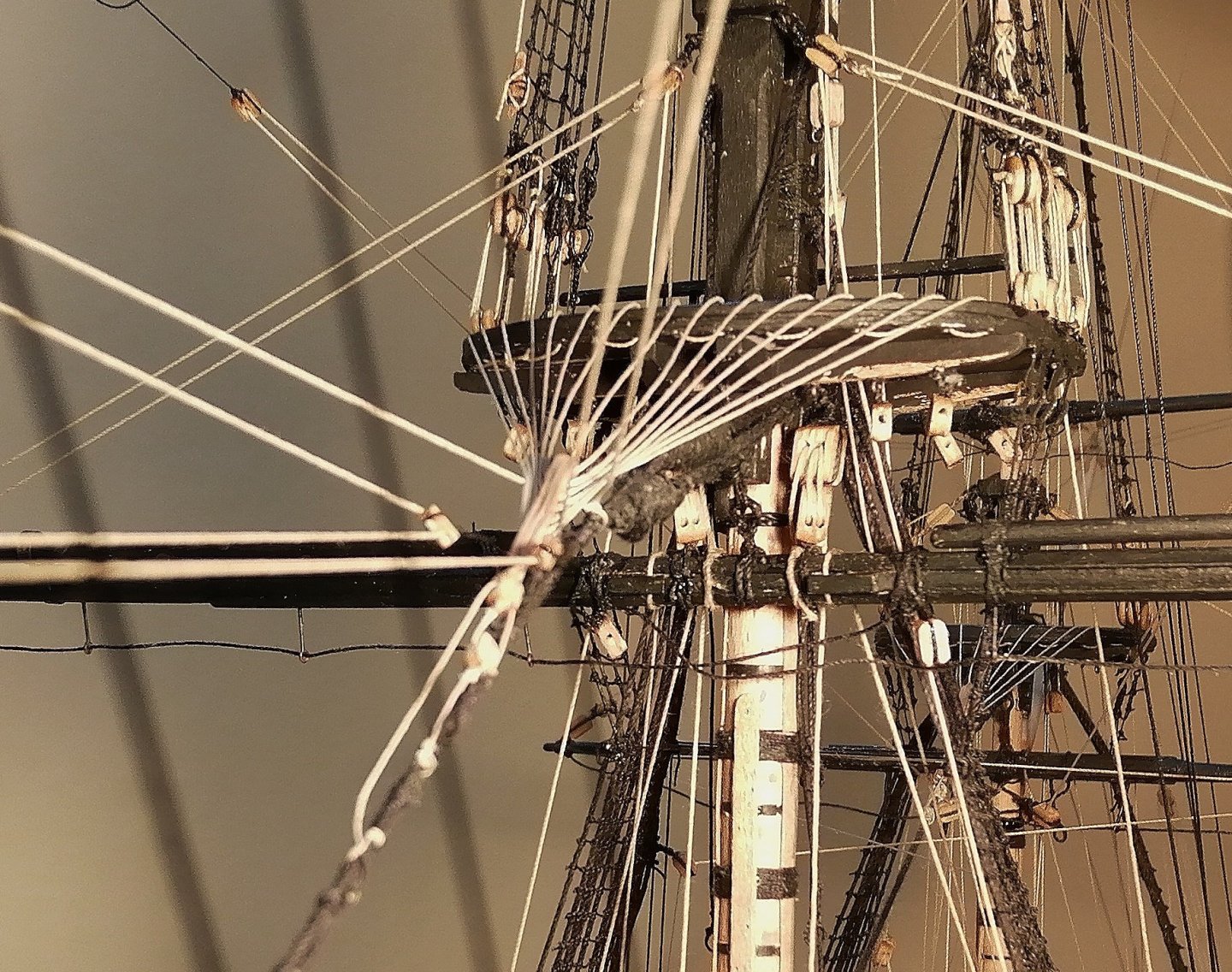
Thanks Tom for the comment and the others for the likes, and I feel it will be cocktail time quite soon! I decided to press on with getting the yards on the masts ~ it's got to get done sooner or later, so now was the time. I had already decided I would work from stern to stem and as the main topsail yard was already present the main yard was next. This was my first adventure at fitting a yard with a nave line, two truss pendants, and two jeers. I began by pushing the sling up through the hole in the top and holding it there by means of a clamp, suspending the yard roughly in position while I made attempts at getting the pendants reeved through their respective eyelets in the nave line and their opposite pendant. I expected to be there a while, perhaps uttering foreign sounding words as I struggled to get the lines where they were meant to go, but I was surprised that I got the job done in fairly quick time with few "misses". Then it was the turn of the jeers. A photo in my previous post above shows the upper jeer blocks lying above the top. I had deliberately placed them there as I imagined that reeving the jeer lines there would be much easier than trying to reeve them through the blocks if they were underneath the top so that's how I did the lines. It was a bit tricky but I managed to get that job done without too much trauma. When I pulled the upper blocks down below the top, the lines were twisted and I had to unpick the lines and do it all over again ~ this time with the blocks in their proper position -- under the top. It was a bit challenging, but not nearly as difficult as I had previously feared it might have been - - - and at least this time I could see that the lines weren't going to be twisted. I made off the pendants, the nave line, the jeers and the lifts but left the braces off as there were still a few lines to be belayed behind the main mast and with the shrouds and backstays I didn't want to clutter up that area any more with the main braces. I moved to the foremast and rigged the topsail yard which was, if anything a little more involving and challenging that had been the main topsail yard as everything is a little tighter around the working areas of the fore mast. Then the fore (course) yard. Well, if I thought the main yard had been challenging, I was about to discover a new meaning of the word "challenging". There were significantly more lines going down the lubber hole in the fore lower top and everything was much tighter than I had found in the same area of the main. On this occasion there were definitely some foreign sounding words uttered and some spells away from the ship in the knowledge that it "would be easier when I returned"! It took more than a happy amount of attempts to get them pesky pendants reeved through the eyelets they were supposed to go through while trying to ensure that they went down the correct side of the multitude of lines already going down in the same tight space. The jeers were equally frustrating, mainly due to the significantly reduced workspace but perseverance eventually paid off. All lines for the fore topsail and course yards have been made off. . . . and last night, Saturday 26th October 2019 was definitely a major milestone in this ship's build as the final two rigging lines were belayed! The main braces had the honour of completing the rigging! . . . unless I've overlooked something ??? In the photo above the fore course lifts and braces still had to be done. (They have now been made off.) That port side bower anchor was just placed in position 'to see how it looked'. That anchor rode won't be the one I will use as it's looks like it's straight from the laundry! I'll want the cables to look like they've been to the seabed! Still have work to do on all the anchors, finish a few carvings at the stern, fit the bowsprit jackstaff, turn and fit the main lower stunsail yards that lay along the main channels - - - and somehow figure out how I;m going to make two somethings that will pass for stern lanterns. And I'm sure there will be a few other things that I'm not remembering right now . . . . .


- 257 replies
-
- 10
-
-
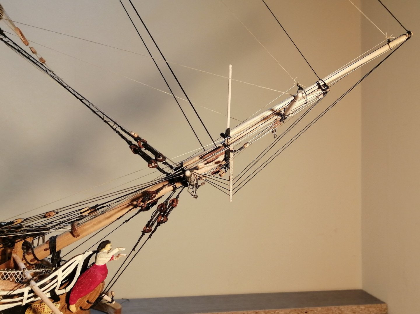
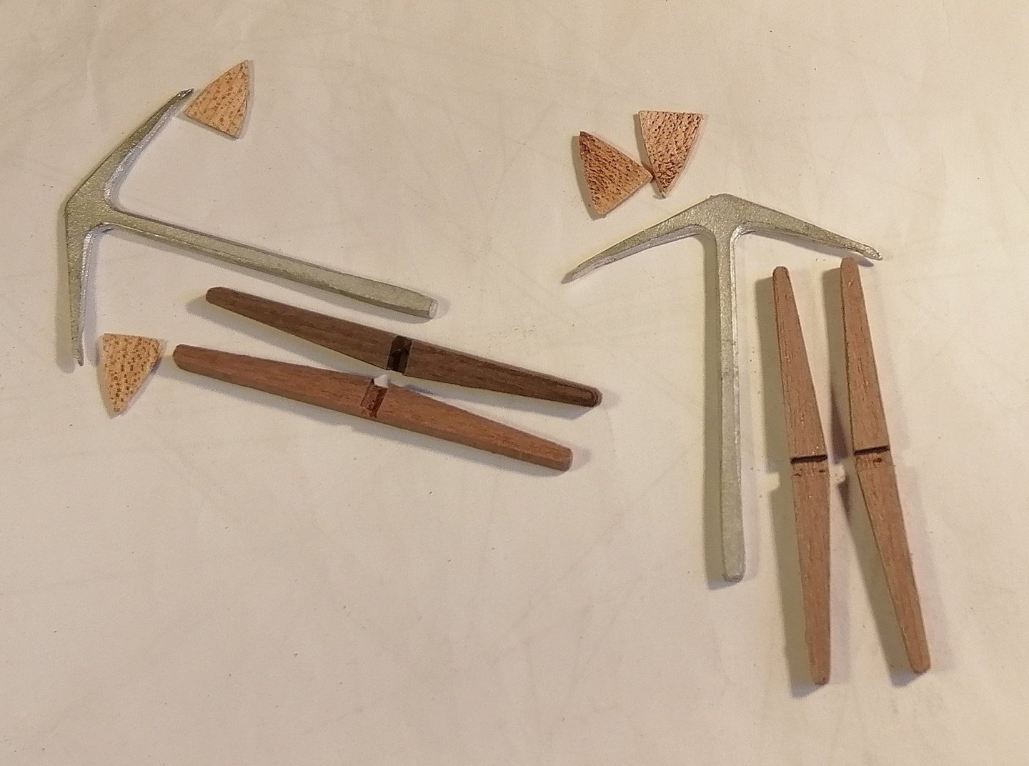
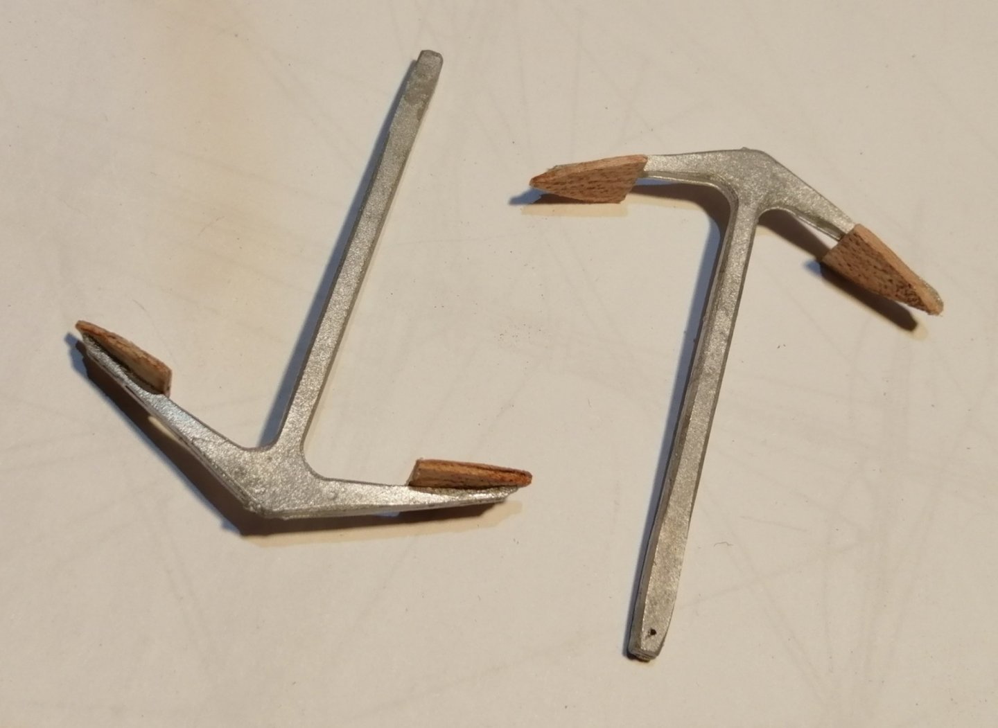
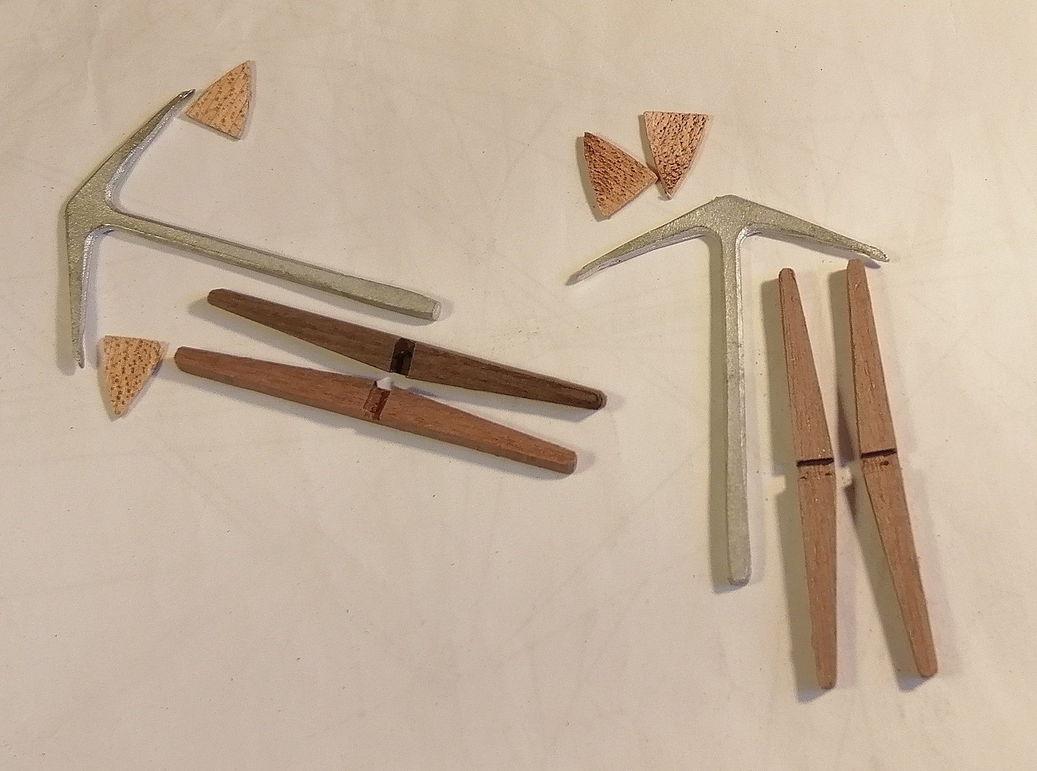
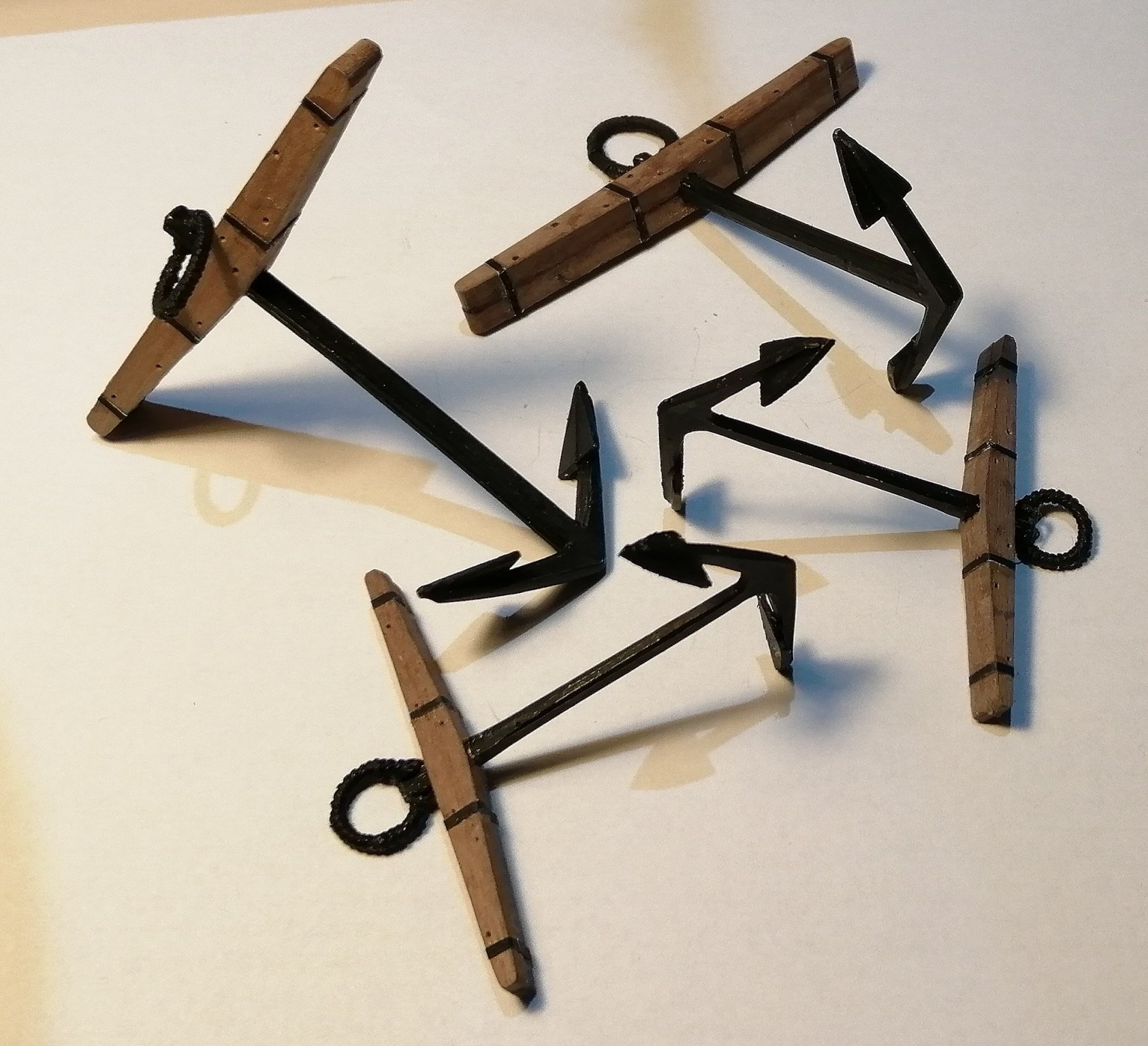
Thanks for your comment, Mustafa. 'Front end' rigging all done now. Martingale fitted and also rigged. That vertical 'stick' above the martingale isn't the bowsprit flagstaff, it's just a cocktail stick inserted where the flagstaff will eventually live. I then fitted the main topsail yard >>> Although the remaining 3 yards are 'ready and waiting' I've held off fitting them for now as there are a few other tasks that now need attention. Among the other tasks are the anchors. The 2 smaller anchors were a bit of a disappointment when they arrived. They only consisted of the basic undrilled anchor and the 2 pieces that make the stock. No flukes or metal to create the ring were included. The above picture also shows the flukes that I had to make. As I had no brass of the correct thickness I cut these flukes from 1mm thick maple that I had previously used for other tasks. I epoxied them on to the anchors. It didn't matter that they were wood as it all ends up black.