Bluto 1790
-
Posts
324 -
Joined
-
Last visited
Content Type
Profiles
Forums
Gallery
Events
Everything posted by Bluto 1790
-
 Rick, Steven and Scott, than you for the further input. Steven ~ I had an inkling that it was a 'back-up' stay, it's just that typically mysterious nautical nomenclature that can be misleading! As for the crossjack, I think I'll go with the double line pendant as above. . . . and Scott ~ thanks for wishing me luck! - - - I'm going to need as much as I can get now that I'm all tied up with this rigging caper!
 -
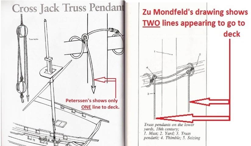
Thanks Mark and Rick for your comments. As my plans/drawings show NOTHING of how any of the yards are attached to the masts I guess I can just go with what works for me. The ship is English from 1790 so I assume it would probably be truss pendants for the mizzen crossjack . . . . . . of course, the plot thickens! - - - Between Peterssen's and Zu Mondfeld's books there are TWO options --- see below >>> So ~ which one is correct ??? . . . or is it again one of those situations "you make your choice and take your chances" ? And how about my other question - - - "While I'm here I might as well reveal the lack of depth of my understanding of nautical language! - - - What is it that the preventer stay on fore and main masts is designed to "prevent"???
-
Although I've been at this build for some considerable time, I'm now just in the beginnings of the masting and rigging. While I've been aware of many of the words in this foreign language of maritime parts I would now like to know the 'whys and wherefores' of some of these mysteries. For starters ~ what is the function of the 'truss pendants' -- I have Peterssen's rigging book and an illustration of the truss pendant is in there and the book obviously assumes that the reader automatically fully understands the functions of everything shown . . . well, this reader doesn't! If the truss pendant serves the same purpose as parral trucks and ribs then why are some yards shown attached to masts by one of these means or by the other? (I'm assuming that a yard can only employ one method or the other and NOT BOTH ??? ) As I said, I'm not sure of the function of the truss pendant, so that's why I'm asking. While I'm here I might as well reveal the lack of depth of my understanding of nautical language! - - - What is it that the preventer stay on fore and main masts is designed to "prevent"??? (Stay tuned to this channel - - - there is a high probality that more basic questions will arrive!)
-
Topmast crosstree dimensions.
Bluto 1790 replied to Bluto 1790's topic in Masting, rigging and sails
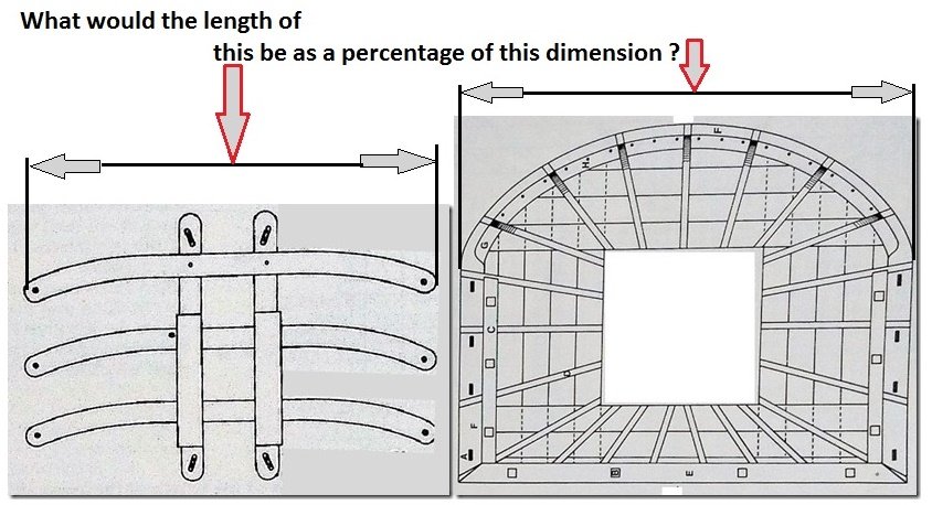
Hi Mark, Thanks for your input. As I said, my plans don't show any dimensions for the crosstrees -- only a vague indication as to the length of the trestletrees. See the pic below >>> In that drawing, (which is at a scale of 1:160) the best measurement I can get of the trestletrees is around 7.5mm so I have to double that to get to the scale I'm working at and that gives me 15mm. So, on the basis of your info above, one and two thirds times that would bring it to 25mm for the crosstrees. The top for the mizzen mast measures about 50mm across so that would make the topmast crosstrees about half of that - - - would that be about the correct relative proportion? (In case you're wondering why I'm working at twice the scale of my plans -- I'M NOT ! . . . it's just that the drawings of the standing and running rigging are only at HALF of the scale of the rest of the ship. It's a bit of a bummer now that I'm at the rigging stage as I have no previous experience so I have to ask questions here, or rummage around in other build logs trying to see if I can get hints and answers there.) Jim.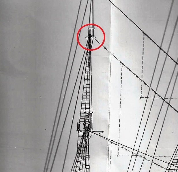
-
There is no indication in any of my plans/drawings as to the length of the topmast crosstrees relative to the width of the equivalent lower mast top. So, in order that my question is clear I've inserted a picture below. Can anyone give me a formula to calculate the topmast crosstrees for each of the 3 masts please? I don't want to just bludgeon ahead and make them to the dimension that "I think" they might be - - - I'd rather they were more accurate than that!
-
Johann, it's just as Carl says, although I should add --- we expect nothing less!
-
Pandora by marsalv - FINISHED - 1:52
Bluto 1790 replied to marsalv's topic in - Build logs for subjects built 1751 - 1800
G'day Greg, ~ I should have known there's always an Australian way to say everything! . . . . . . must get myself an Australian Thesaurus . . . Jim. -
Pandora by marsalv - FINISHED - 1:52
Bluto 1790 replied to marsalv's topic in - Build logs for subjects built 1751 - 1800
Marsalv, your entire build looks okay, quite good, very good, excellent . . . Oh, I think I'm trying to say IMPOSSIBLE! - - - just like the words I am trying to find. -
It's looking really great, Tom, and I'm looking forward to seeing the stern quarters lit up. HOWEVER ~ I'm afraid that 'summer weather' is no excuse for slower progress !
-
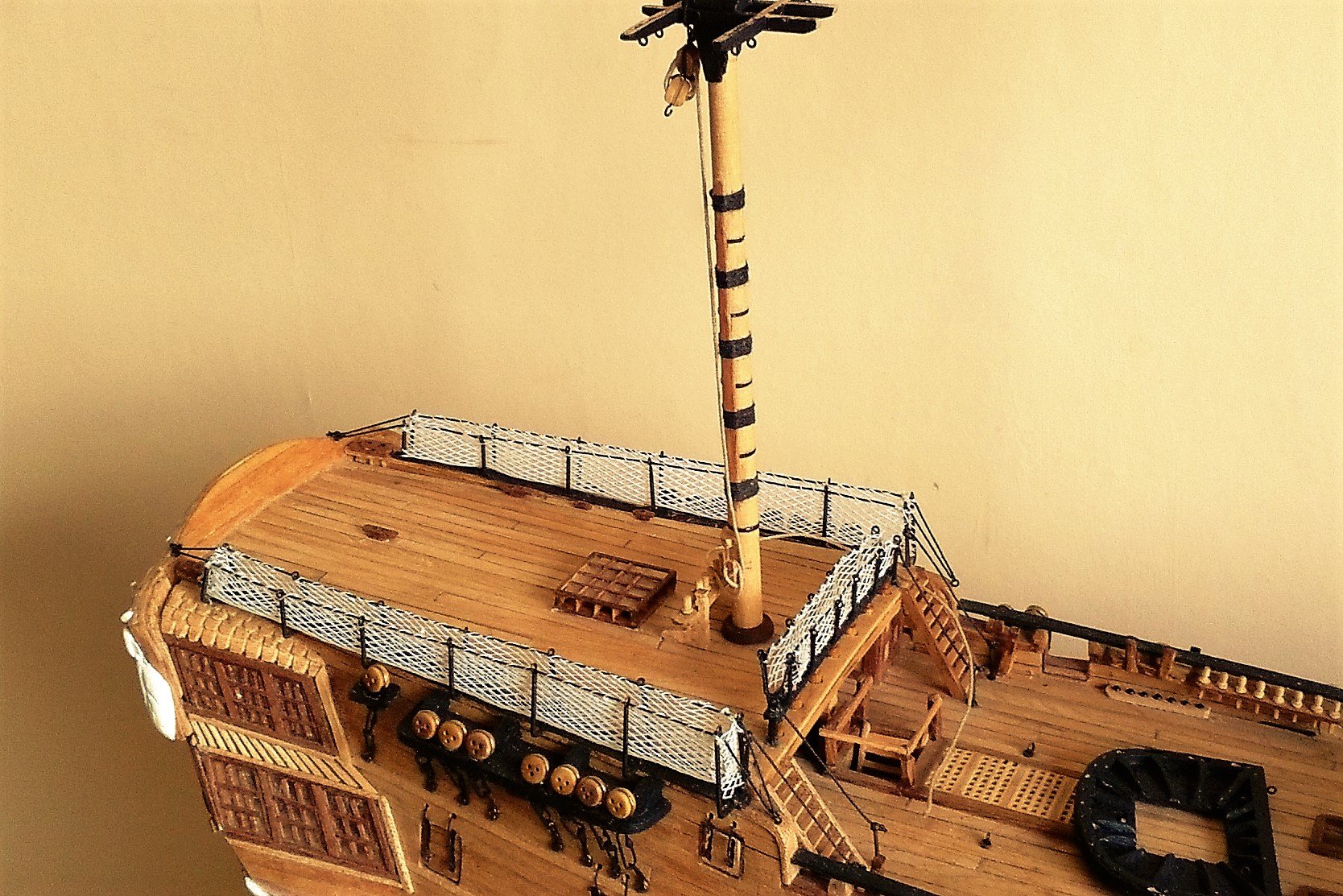
Gregory, Frankie, Henry and Gary -- thanks for your comments. As this is my first time of arriving at the prospect of doing all the rigging I find it a bit bewildering especially when there is a total lack of details in the drawings/plans -- only what can be seen in the photo I posted above. I guess I'm tending to be over-thinking this thing and since I've considered your comments I can see the answer to this main brace question (in fact it might just be 'staring me in the face'!) However, as can be seen in the photo below, the poop deck of Leopard is completely devoid of bulwarks -- there are only hammock cranes along both sides. There is though, a snatch block mounted at the extreme aft end of each side immediately ahead of the base of the taffrail. I hadn't really considered these to be used for the main braces, but I can see that they're my answer along with the deck mounted cleats that Frankie mentioned. (even badass cleats!)

-
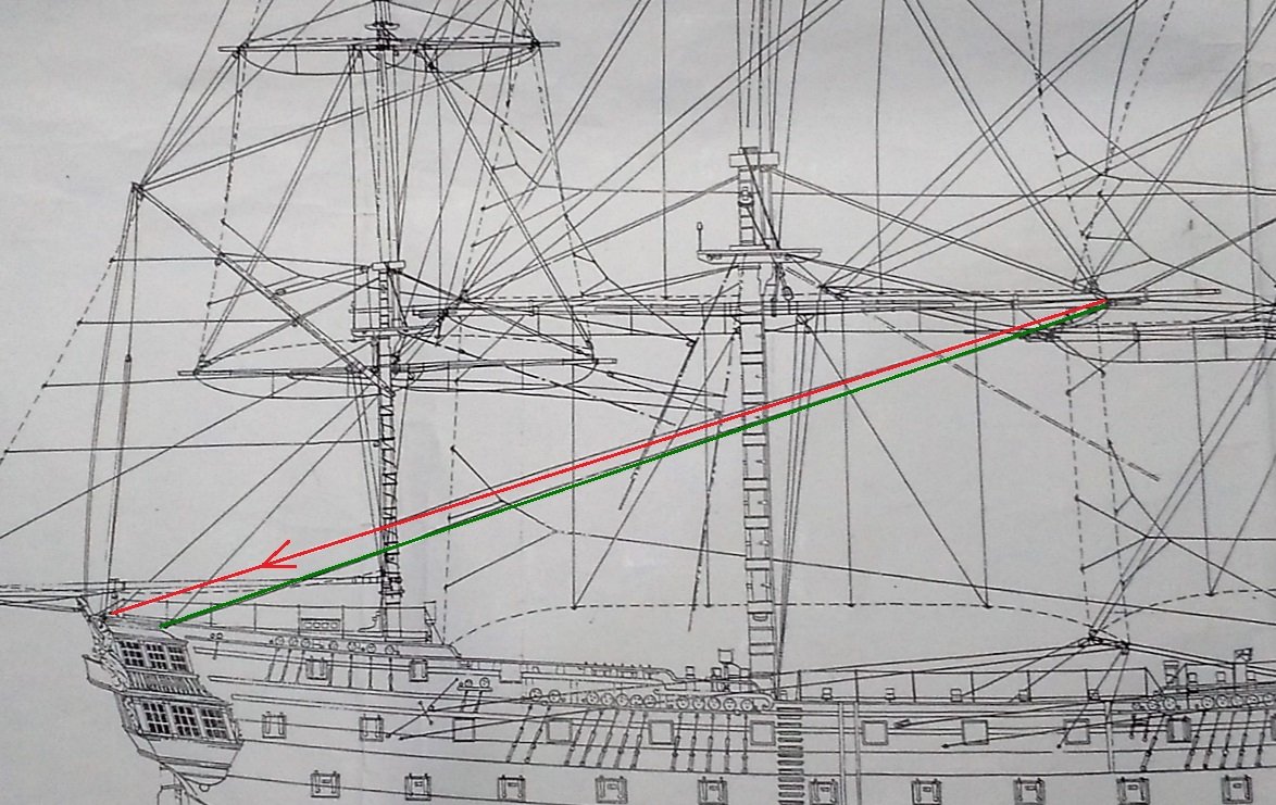
Well, it's not that I don't know where they are, but specifically, it's not very clear where the main brace is cleated/secured. On the drawing I have it shows the running end of the main brace heading (as seems to be the normal) towards the aft end of the poop deck just below the taffrail. In Peterssen's rigging book it shows that line passing through a sheave in the bulwark and being cleated off to a pin on a pinrail on the inside of the bulwark. On H.M.S. Leopard it's not possible to secure it there as there are no bulwarks on the poop deck -- only hammock cranes . . . see the drawing below where I've highlighted the running end of the brace in red and I'm assuming the fixed end is the one in green >>> It doesn't seem feasible to secure it to a cleat on the taffrail even if there were any there. (there are none in any of the drawings/plans) I'm thinking of continuing to run the line from the taffrail up to a block under the mizzen top and then back down through a series of blocks to a belaying point below. It's just that to do so would seem to make for a very long, convoluted main brace ??? Any comments ?

-
Johann ~ as always, I'm staggered by the quality of your work! I've just been doing some futtock plates and I have copied your design. (Well, at least I've done my own version of your design.) I 'trapped' the deadeyes in the metal strop before soldering the strop to the plate. I see you must put the deadeyes inside the strop AFTER soldering. Do you have to squeeze the metal strop a little to keep the deadeye from popping out?
-
Hi Marc, I'm glad I found this post of yours. I've just recently arrived at the masting and rigging stage of my build and have been trying to think of all the difficulties that lie ahead if I go ahead and fit something 'now' that should be fitted 'later' and vice versa. I've already made the mizzen lower and topmast and the main lower and topmast and when I look at them in position (they're just loose, not secured yet) and visualise all of the shrouds in position I just can't think how I would be able to fit the yards . . . so I'll definitely be fitting as much as possible 'off ship' before stepping the masts.
-
Rigging Question (Probably first of many!)
Bluto 1790 replied to Bluto 1790's topic in Masting, rigging and sails
Allan, Just as you say (and as I already said), Peterssen's book is pretty much specific to one model. It provides, however, a fairly comprehensive guide to where all the rigging lines go - - - it's just that in many cases the 'end point', i.e. the belaying position, just isn't in the same vicinity on 'Leopard' so some inventiveness will be required. As I won't be having sails on the ship there will surely be a few vacant belaying points that can be used. As for scratch building, it would probably be more accurate to say that it's about a 90 to 95% scratch build as there have been some items that have been 'over-the-counter' purchases, so it is a bit of a compromise. Things like all the countless deadeyes, blocks and rigging lines have been bought, and while I scratch built the carriages, I did buy the cannon barrels as I don't really have the resources to turn metal (not to mention the lack of experience in that venture!). Apart from these items just about every other aspect and part of the build has been 'scratched'. -
Pandora by marsalv - FINISHED - 1:52
Bluto 1790 replied to marsalv's topic in - Build logs for subjects built 1751 - 1800
Marsalv --- can you please get someone to come and wake me up because I know I must be dreaming! I know none of the things in your pictures can be real !!! W-O-W !!! -
ancre La Salamandre by tadheus - 1:24
Bluto 1790 replied to tadheus's topic in - Build logs for subjects built 1751 - 1800
You're welcome, Pawel! -
Rigging Question (Probably first of many!)
Bluto 1790 replied to Bluto 1790's topic in Masting, rigging and sails
Thanks to Ulises Victoria, Gregory and Frankie for your further comments. Gregory said: "If you will notice, the number and set-up of those stays of your 50 gun ship, appears identical to Ptersson's frigate. As far as belaying, taking the natural lead of the line to the closest pin, while avoiding interference with other lines, will probably not get you in trouble with any Admiral who may view your work." I realised after I posted my previous comments that I probably gave the impression that I'm of the opinion that Petersson's book won't work for my 'Leopard'. That's not the case and I fully realise that the book will be invaluable to me once I get properly started with all those ropes and tying knots and as Gregory said, I'll just have to be inventive with the 'closest pin.' Frankie ~ I haven't seen the Peterssen book that you have but the one I have seems to be fairly reliable. I'm sure it will suffice for the amount of rigging that I intend to do. I intend (hope!) to have masts and yards (no sails) with the bare minimum of required rigging without anything becoming over-complicated. If I end up with something like the ship below I'll be happy >>>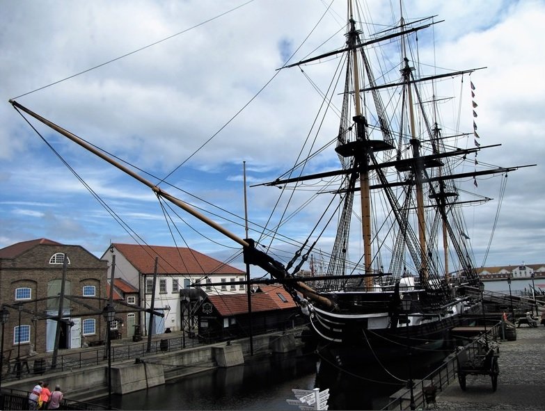
-
Rigging Question (Probably first of many!)
Bluto 1790 replied to Bluto 1790's topic in Masting, rigging and sails
iiihmb, Danny, Gregory, Ulises Victoria and Jan ~ thank you all for your very quick replies! Ulises Victoria wrote: "Hello Jim. Try to find Rigging Period Ship Models by Lennarth Petersson, or the more expensive The Masting and Rigging of English Ships of War 1625-1860 by James Lees They will provide you with specific details on how to fix those lines in your model. It seems to me that since you are tackling a very advanced method of building (scratch building) it is taken for granted that you should already know those things. Cheers." - - - Actually, apart from a very crude attempt ("very crude" doesn't really describe it!) several years ago at building a ship . . . a ship that never actually existed but was made without any plans just as I imagined it might be, I've never even had a go at even the most basic kit build. This is my first foray into the world of building a model of a ship that actually existed. When I started the build over six years ago I wasn't even aware of the existence of this, or any other great resource for ship modellers, but I'm sure glad I found it coz I know all you good guys are always here to help! Oh ~ and you're right --- after all this time I SHOULD know all these things! (But I don't!) And this is even more embarrassing ~ I DO have a copy of Lennarth Petersson's rigging book. However, what I have found is that his book is pretty much for the rigging of a frigate and the configuration of the positions of the belaying points on this 50 gun ship are really very different. I know I'll just have to be a bit inventive and adapt and apply the principles in his book to the layout of my model . . . . . . of course, that doesn't mean that I won't be coming back here with more stupid questions! -
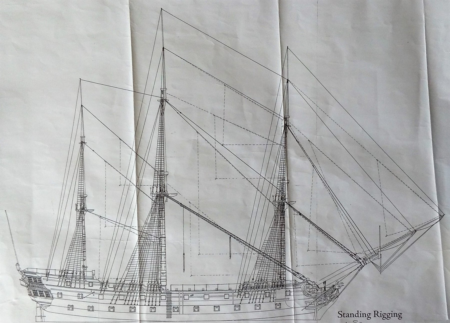
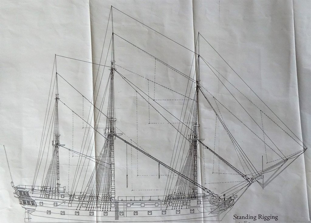
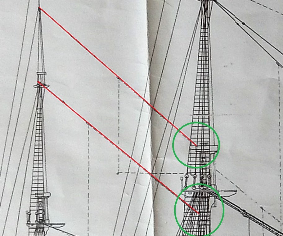
I'll soon be starting the rigging on my scratch build. The ship is HMS Leopard and I'm building it (or, attempting to build it) from the very basic plans and drawings contained in Rif Winfield's "The Fifty Gun Ship". Drawings by John McKay. Here is the one and only drawing of the standing rigging >>> It doesn't provide any helpful details as to how so many of these lines are attached to masts, spars etc. etc. I've isolated just one section of the above picture to ask how the stays for the mizzen topmast and the mizzen topgallant are attached to the main mast ??? I'm assuming these stays must be adjustable but the drawing shows nothing meaningful. In the following pic I have highlighted these stays in red and would like to know the method of how they're fixed to the main mast in the areas of the green circles >>>
-
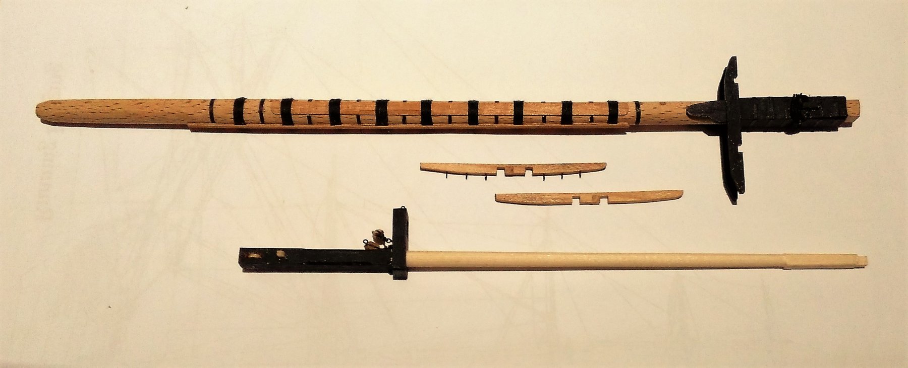
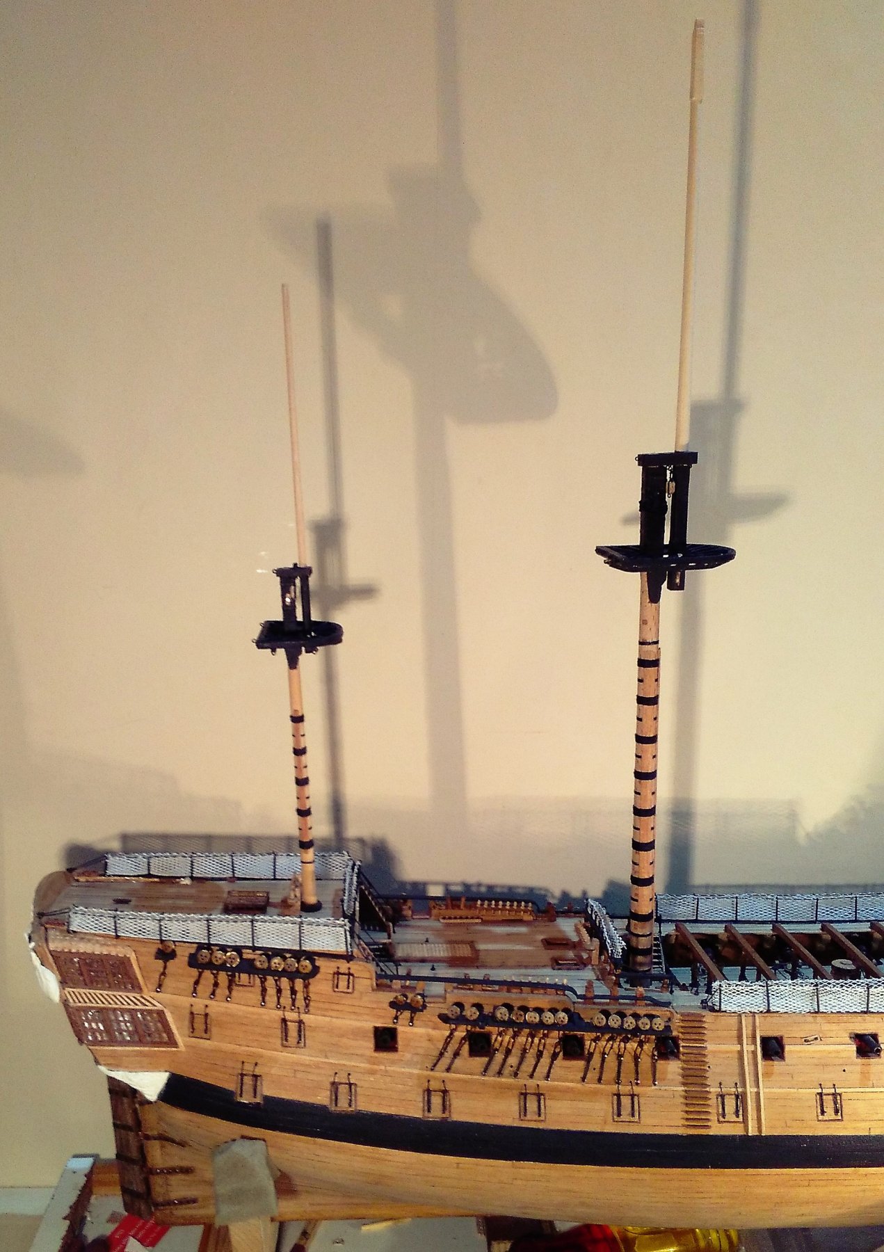
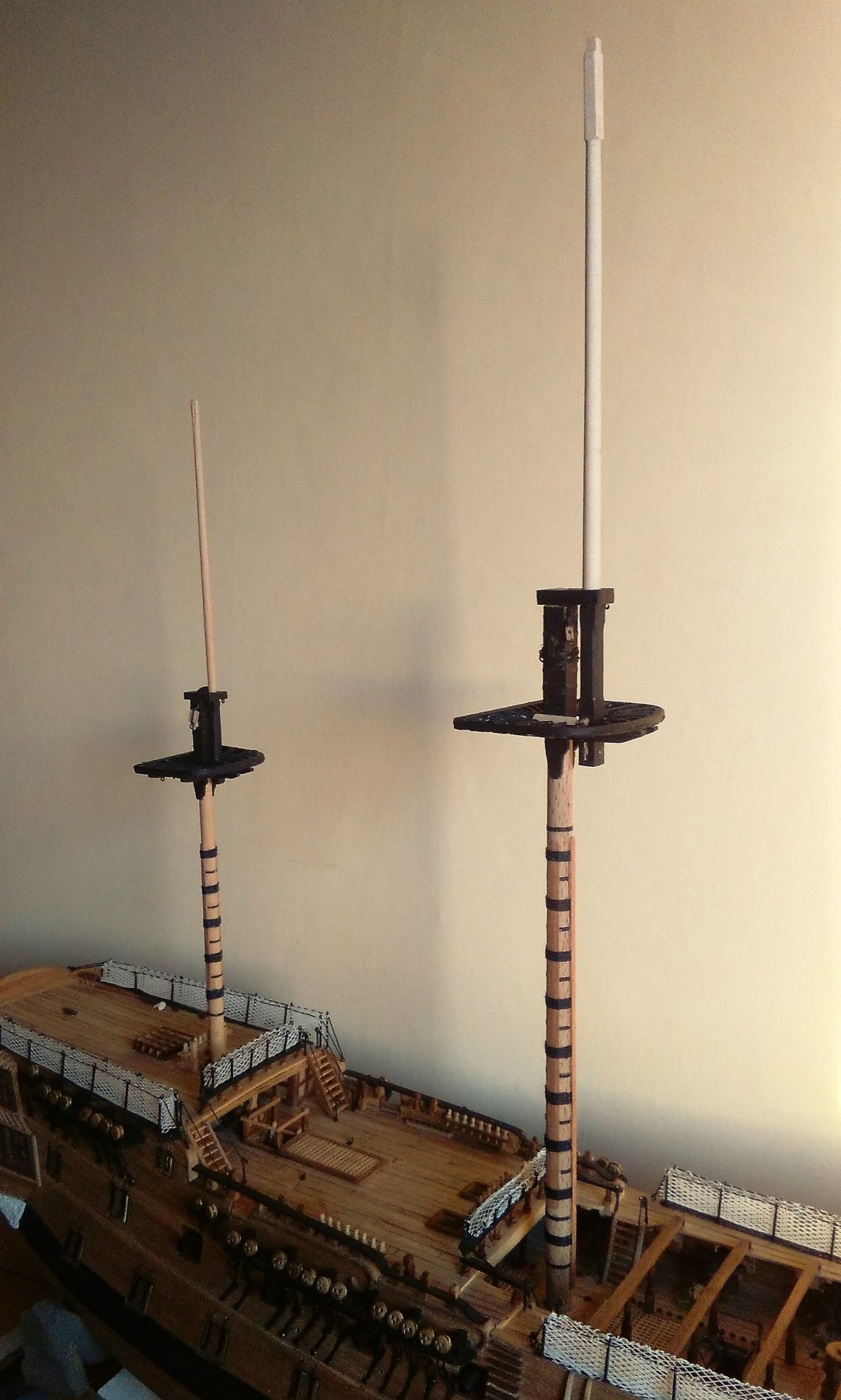
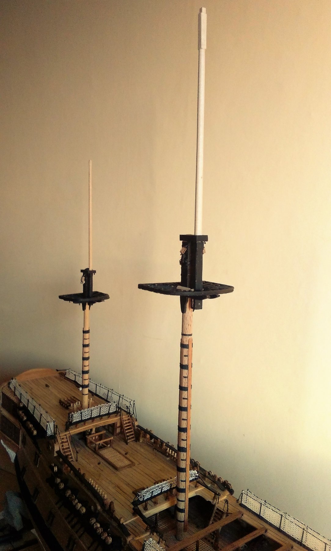
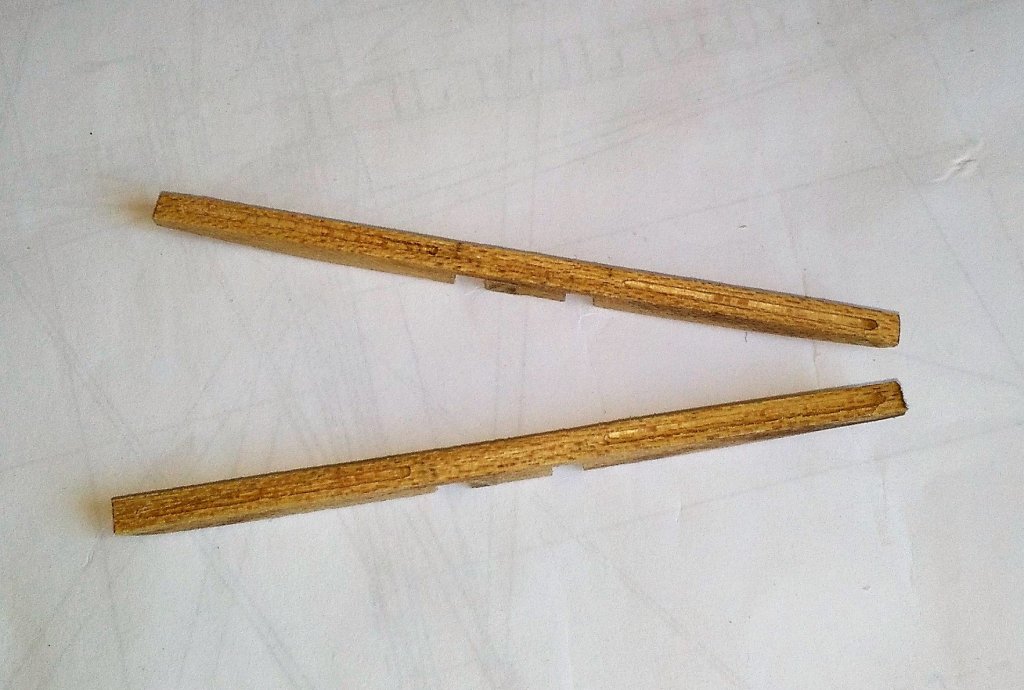
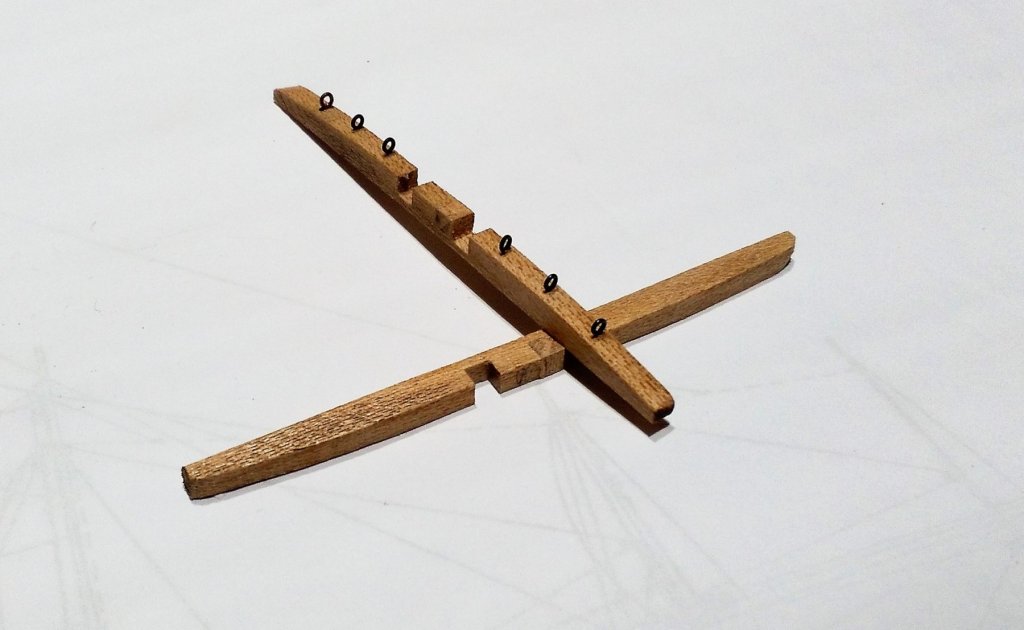
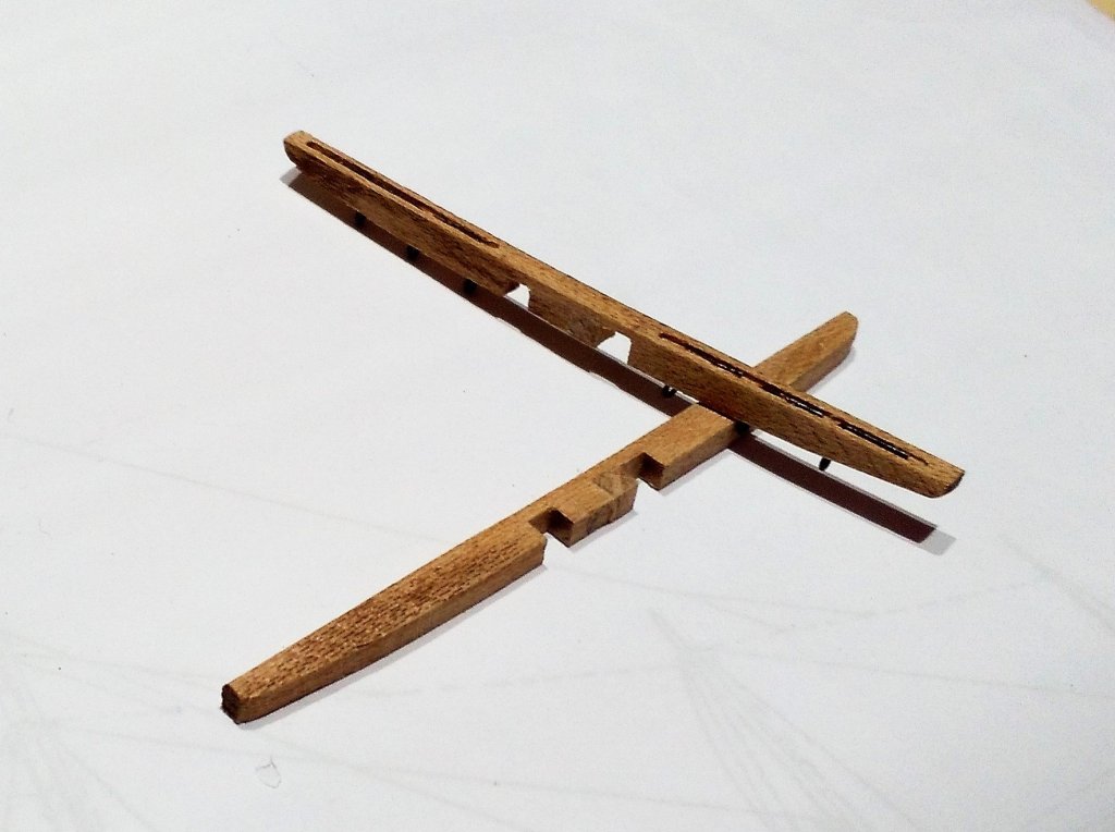
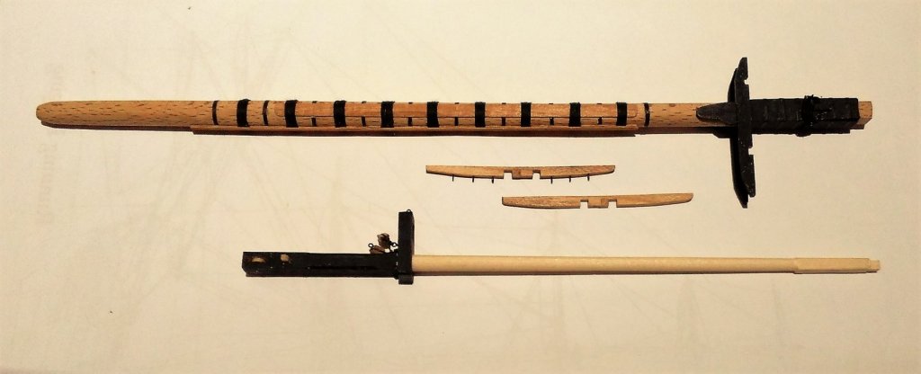
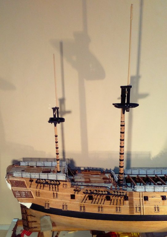
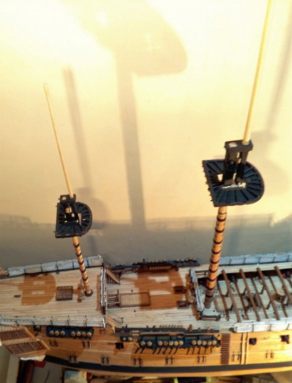
Leaving the mizzen topgallant and royal to be done later, I've moved on to the main. My plan is to build the three lower masts and topmasts before tackling the uppermost masts. I don't know if it's the right plan - - - but it is my plan. Learning a lesson from doing the mizzen lower mast, I started with a much bigger than required dowel and turned it down to the diameters required for the mainmast, leaving the masthead area untouched. In the milling machine I squared off the masthead and also milled the square tenon, but this time (unlike with the mizzen) the masthead was the correct dimension without having to be 'beefed-up'. (I've been at this build for over six years and I'm still learning from each different 'procedure' . . . AND I've still got a whole lot more to learn!) Apart from the above, just about everything I did for the main lower & topmast was what was done for the mizzen lower & topmast, except everything was on a larger scale. As there are rings (for blocks) attached to the underside of the crosstrees, I milled two 0.8mm wide X 0.8mm deep grooves in the upper sides of the crosstrees >>> These grooves were so that I could bend over the tops of the shanks of the rings so that they would be trapped in their positions without using glue >>> The main topmast still has a few minor details before it's finished and while it's not clear from the vague drawings I have, I milled a slot and fitted a sheave in the heel. If I don't find a use for that sheave at least it is already there and there will be no regrets that I didn't fit one in case it does find a use. It has taken me around a month to finish the main lower mast with all of the 'stuff' that has to be done to it. It's virtually finished now . . . until I discover something else that I've forgotten >>> Temporarily in position here along with the mizzen lower and top masts. The tops and the main crosstrees won't be fitted until the shrouds are in place. Without thinking ahead I went and fitted the crosstrees for the mizzen top >>>


- 257 replies
-
- 14
-

-
Johann, As Michael said -- the deadeyes and plates look great -- just as all of your work! . . . and as I'll soon be at the futtock shroud plates in my build this is just another one of your posts that is on my bookmark list !
-
ancre La Salamandre by tadheus - 1:24
Bluto 1790 replied to tadheus's topic in - Build logs for subjects built 1751 - 1800
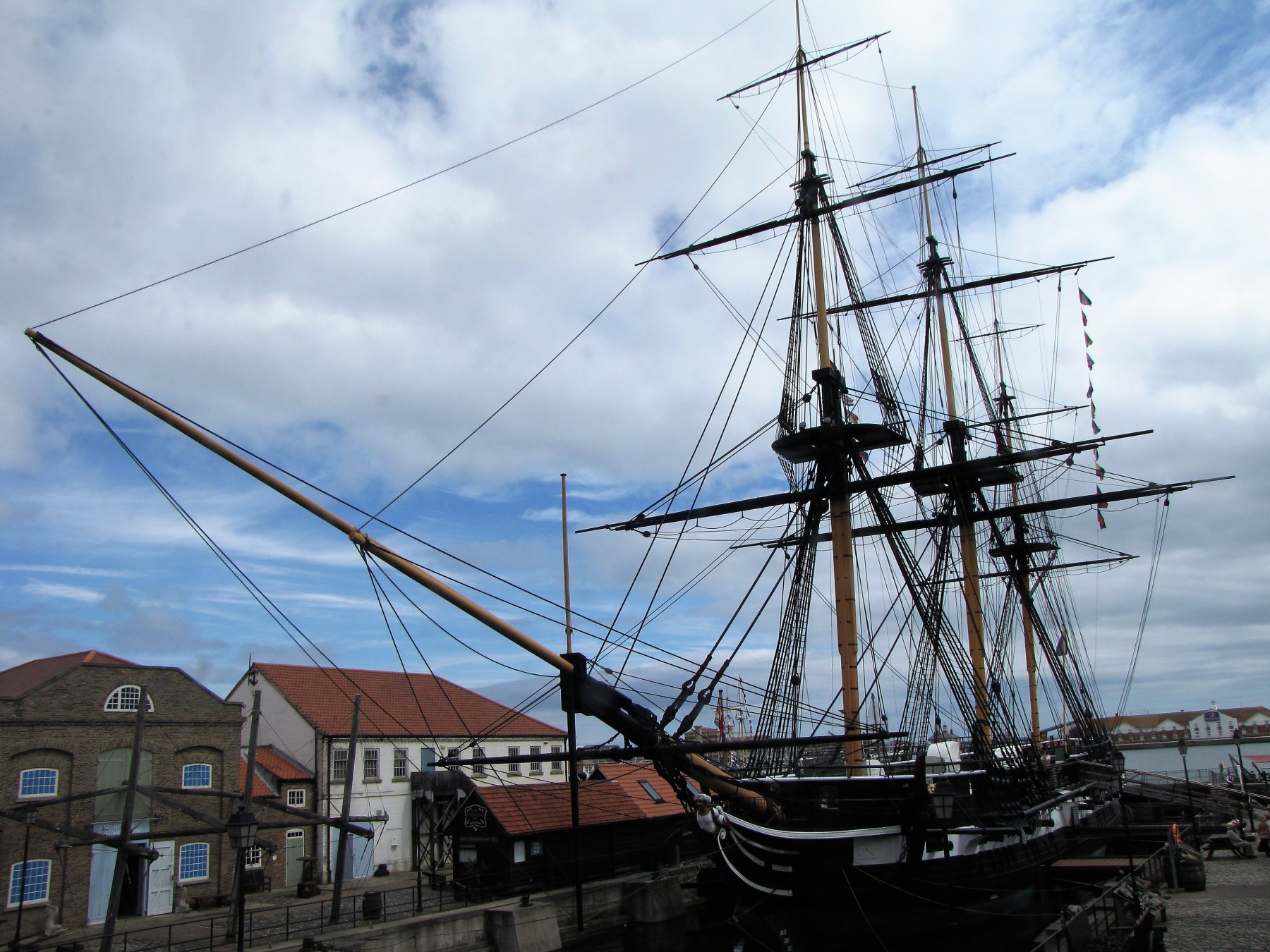
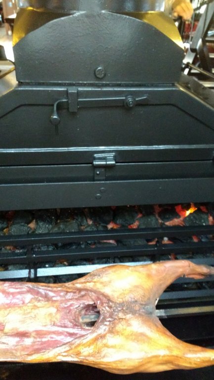
Hi Pawel, I've just been visiting H.M.S. Trincomalee in Hartlepool (England) and the stove there is depicted with glowing coals while the cook stands at the other side preparing a meal. I guess if you wanted you might be able to use something like red or orange coloured cellophane ??? Here's the stove - - - the faintly glowing coals can just be seen behind the grill >>> Edited to add a better photo of the glow -- this was on my wife's phone, I didn't know she had taken this picture! >>>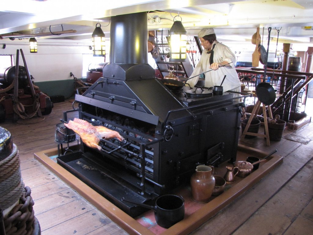
-
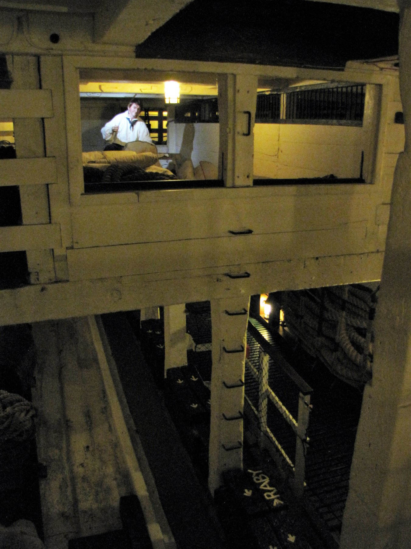
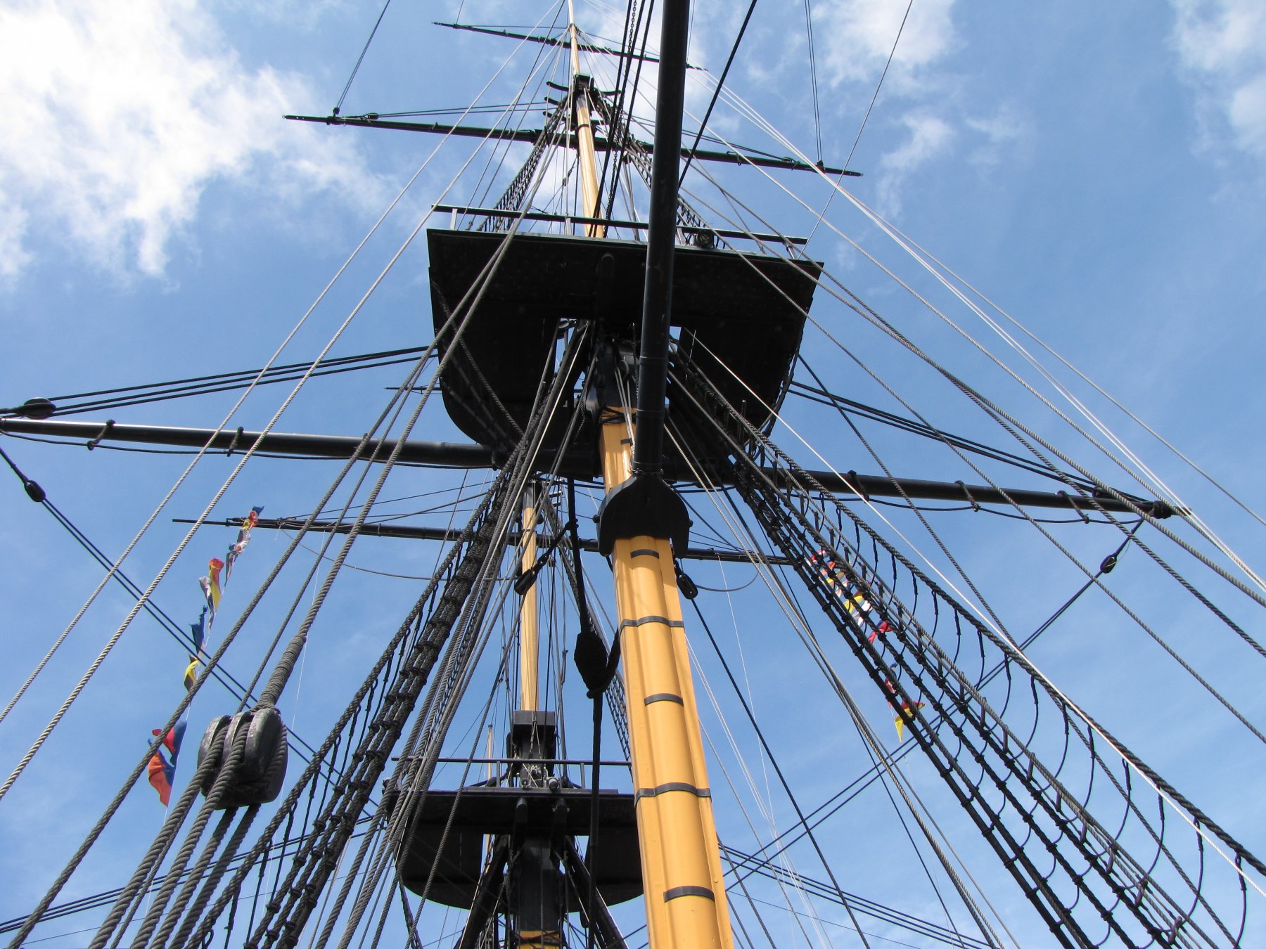
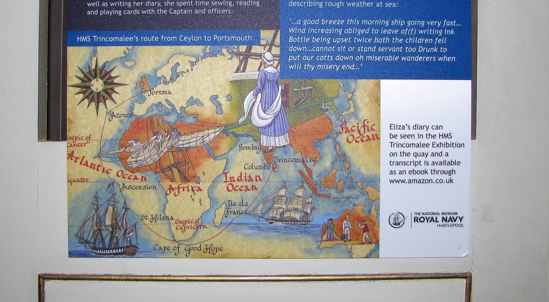
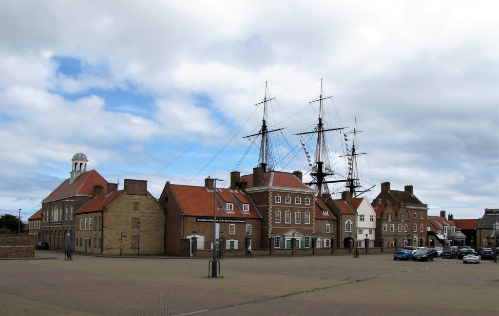
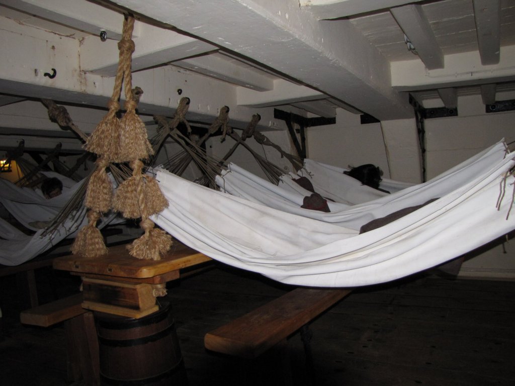
Okay Tom, Here's some Trincomalee stuff. The first pic below shows what can be seen when down in the seafront area at Hartlepool >>> This is all that can be seen of the ship before paying the entrance fee to get to the other side of the buildings where the ship is berthed. The ship sits in it's own dock surrounded by a "U" shaped collection of these buildings which were built to replicate an 18th century dockside. Despite their 'old' appearance I believe they've only been there since around 1994 It wasn't very easy to get meaningful pics of the ship due to it's size and the relatively restricted area in which it is docked but here are a few which I considered interesting. First, a general view from inside one of the buildings >>> Being a Frigate, it's not one of the biggest of the ships from the days of sail, but I was a little surprised at it's relative large size. It's length is given as 180 ft - 'stern to prow' - and I'm guessing that means from the aft end of the spanker boom to the tip of the flying jib boom. I was also surprised at the headroom in the main gun deck. I'm almost 5 ft 9 ins (1.75M) and I was able to walk around under the deck beams and hardly had to duck, with my hair (or what's left of it) just brushing the beams. In the lower deck the headroom was just a few inches less. The orlop deck was a different story -- you would have to have been one of the boys to be comfortable walking around there! However, there wasn't a whole lot of orlop deck as it gave way down to the hold and a fair length of it effectively had a double height 'ceiling'. Not being too familiar with the layout of these ships away down in the hold area, I found the arrangement for the sail loft interesting. It was effectively suspended well off the keel and away from the hull sides to keep the sails well away from any source of wet or dampness and the only way in and out of it was by the 'ladder' shown in the following pic >>> Since it's restoration, the masts are tubular steel and all the ropes are synthetic . . . which makes some sense as they are much more durable than were the original items >>> I guess that most of these historic ships have their own unique stories, and Trincomalee is no exception. Here's one >>> On the lower (mess) deck there are several hammocks rigged to show visitors how the sailors slept. Back in 2003 I sailed on H.M B. Endeavour (replica of Capt. Cook's ship) and NO-ONE would have been able to have slept like that! In this pic below the hammocks are almost lying on the tables.The hammocks have to be tightened until they're much more horizontal than shown here, although that doesn't make them very easy to get into. (On the other hand, falling out is relatively easier!) I realise they're depicted like the photo so that visitors get the idea of what the mess area was like >>>


-
Tom, I think that if you've got a hankering to fit these lights then (if it was me) I'd go ahead and fit them. If you were to fit them and never use them then you'd have lost nothing but your time and the cost of the materials ~~~ if you don't fit them and later you find you'd really have liked to light up your ship then you'll be kicking yourself. (Go ahead - - - ask me how I know such wisdom !!! ) I'm off on a trip this weekend to visit H.M.S. Trincomalee, the oldest English warship still afloat, berthed at Hartlepool, so I'll have a break away from the miniature world of sailing ships and into the real one.
-
Hi Tom, Progress IS progress! I see your signature includes the maxim:- "Attitude is the difference between ordeal and adventure." Perhaps 'attitude towards planking is the difference between professional help and no need for professional help!'