HOLIDAY DONATION DRIVE - SUPPORT MSW - DO YOUR PART TO KEEP THIS GREAT FORUM GOING! (Only 44 donations so far out of 49,000 members - C'mon guys!)
×


Bluto 1790
-
Posts
324 -
Joined
-
Last visited
Content Type
Profiles
Forums
Gallery
Events
Everything posted by Bluto 1790
-
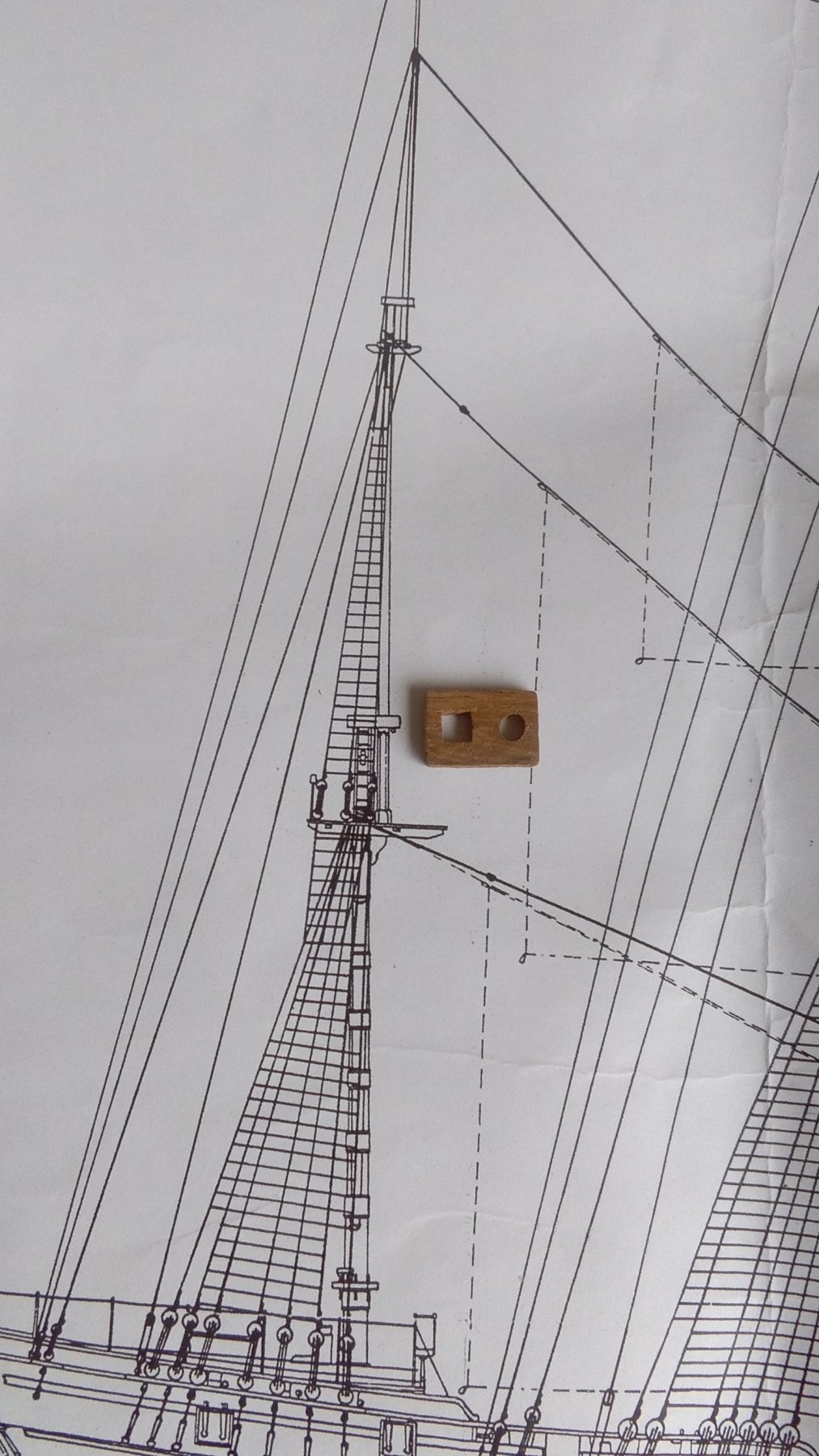
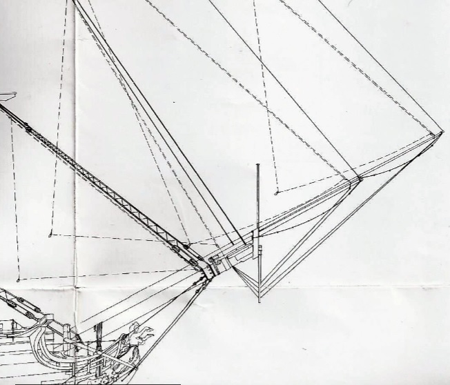
 Hi Tom, When I first started I struggled a bit to find somewhere to get the plans expanded from 1:96 up to 1:80. One company I contacted wanted to charge an arm and a leg to do it! ~ I eventually found a place that did the job for just a few £££s . . . but that company no longer exists! In any case, when I expand any part of the drawing in my very basic photo editor (which can only handle small parts of the drawings) the result is just a bigger picture but everything has just become even less distinct as can be seen in the following image. Even at that enlarged size all of the details that a modeller would need are just not contained in the drawing so I went trawling through the forum to find a build log that shows what I need to see . . . and I found one that contains a decent amount of good quality photos of detailed masts and rigging, so I'm constantly referring to that. (Thanks to Arthur!)
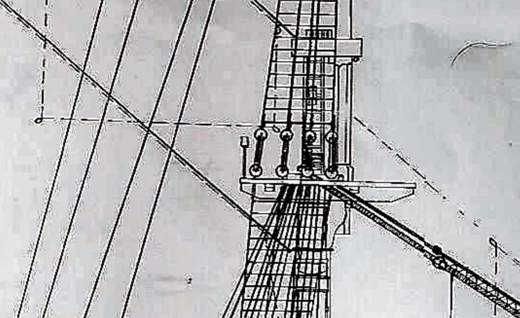
-
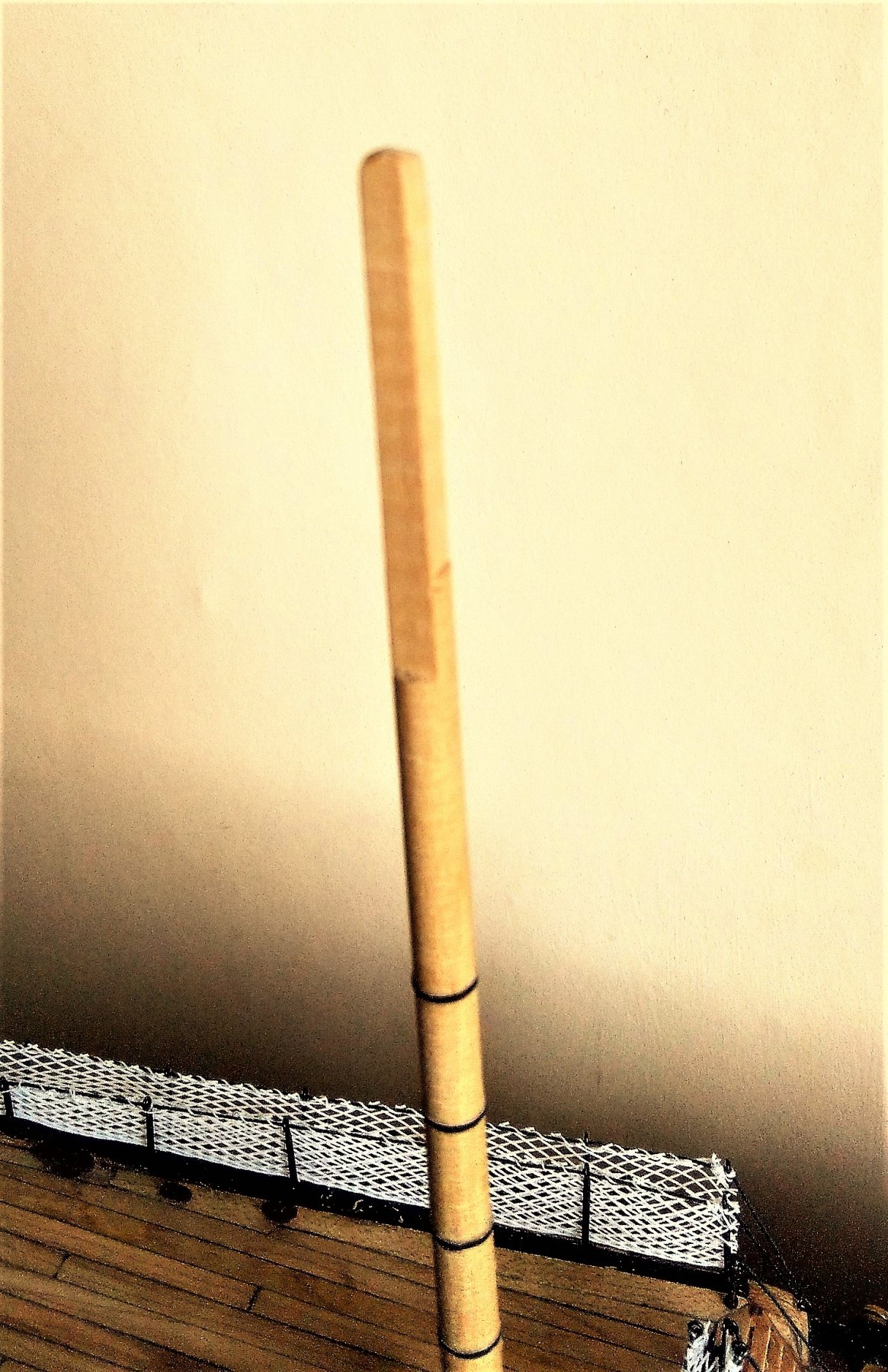
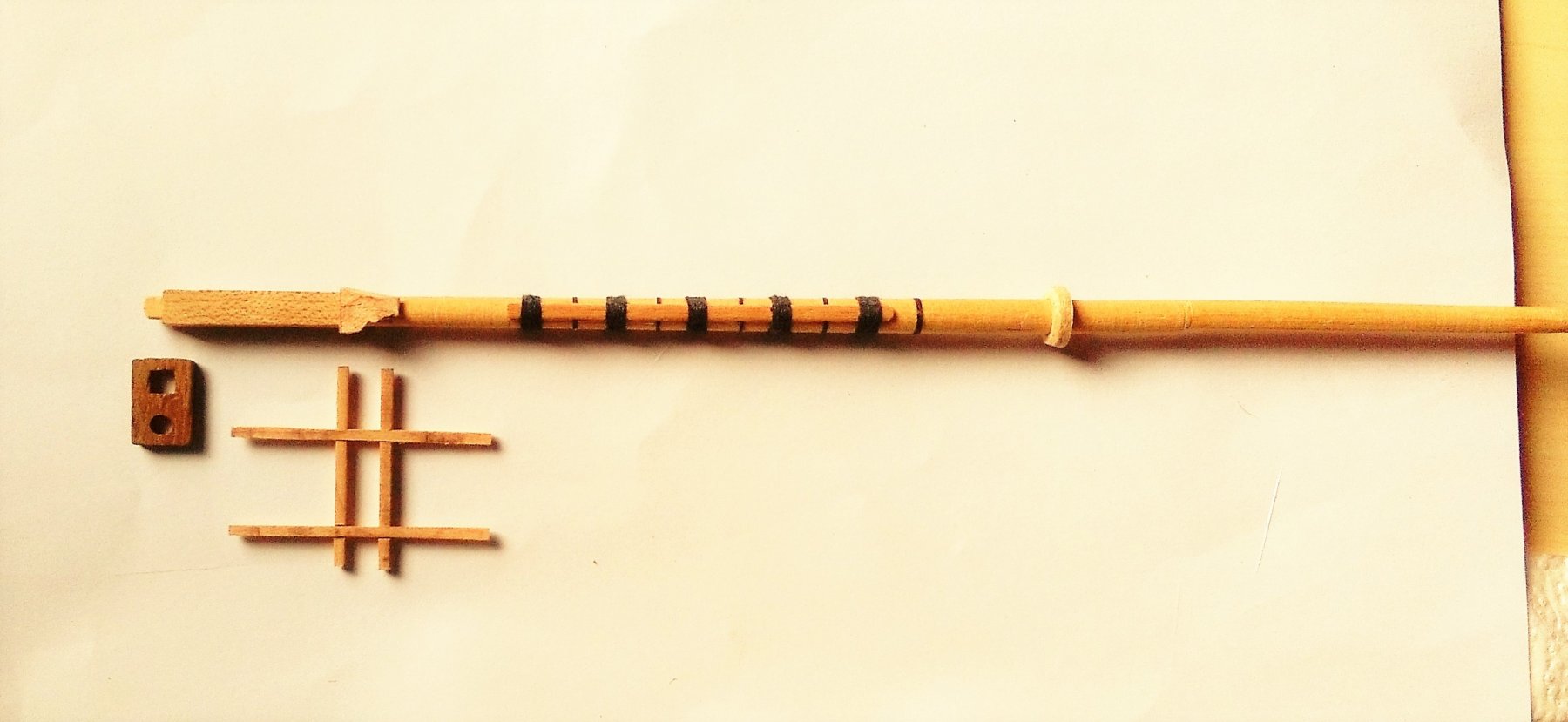
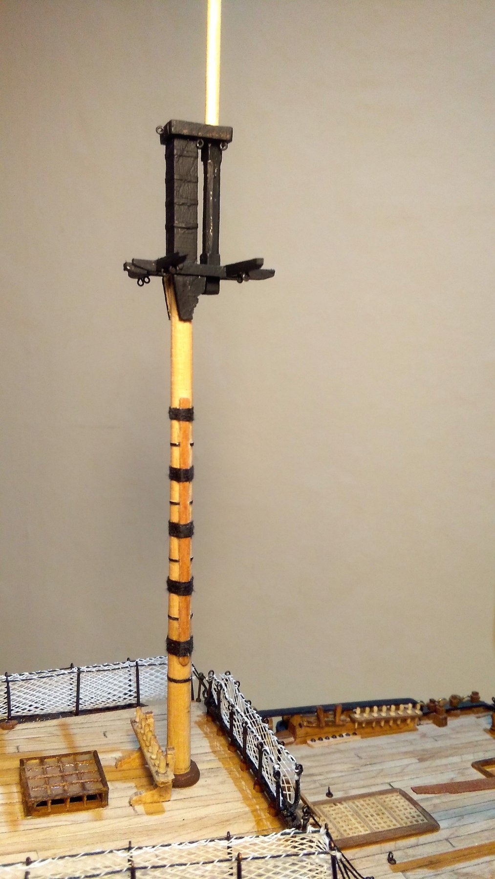
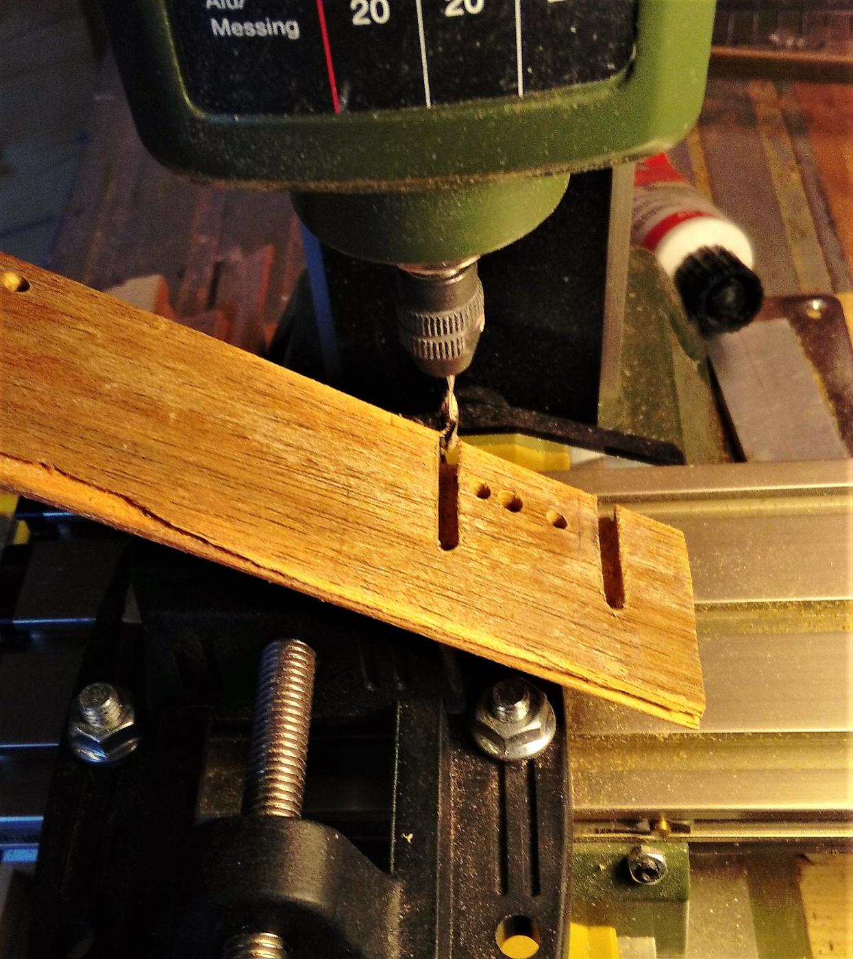
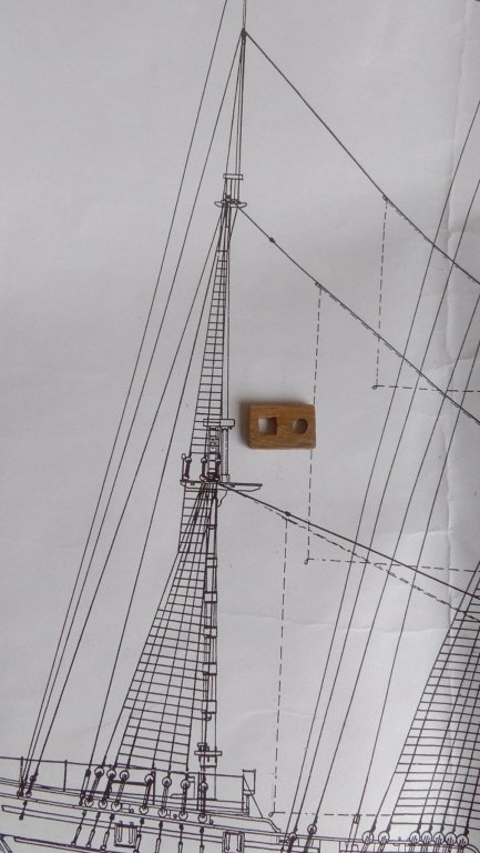
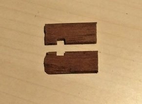
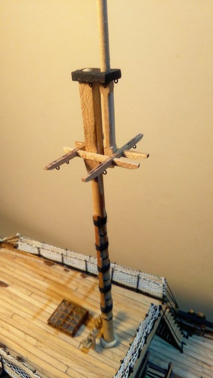
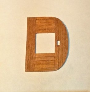
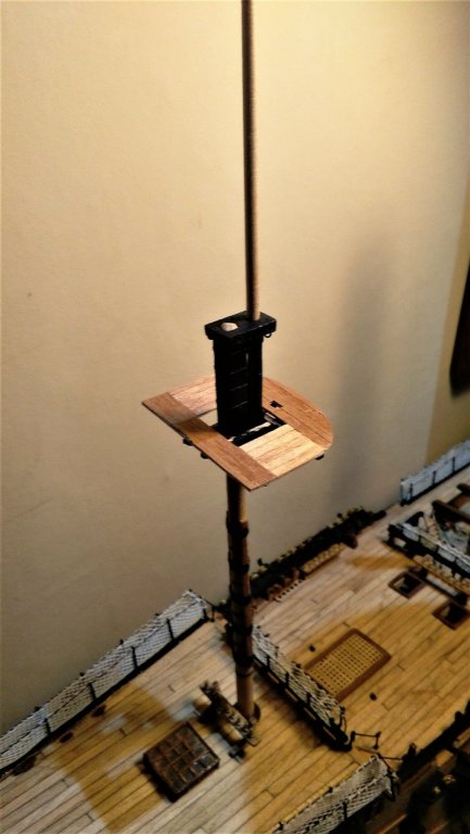
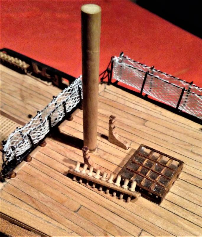
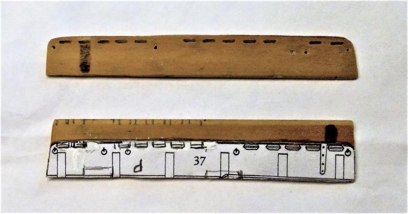
Thanks Tom and Popeye for your comments, and to the others for the likes. Made a start into the world of masting and rigging with the mizzen. Being the smallest of the 3 masts it's probably a little trickier to work ~ especially trying to turn that skinny topmast - - - and I haven't even made an attempt at the even skinnier topgallant. There are no detailed drawings/diagrams for the masting and rigging. There is only one drawing for the standing rigging and only one for the running rigging and both of these are at half of the scale at which I'm building the ship, so I have to measure every item on the drawings then double that dimension to get the size I require. Here's the mizzen lower mast cap laid next to the cap on the drawing >>> That square mortise in the cap is only 4mm and I couldn't think how I would be able to make a neat job of that while messing around with files and things, so instead I clamped 2 pieces of wood in the vice and milled a cut 4mm wide but only 2mm deep in both pieces at the same time >>> The 2 pieces were then glued together and the square hole looked OK. It was then easy to drill the round hole for the topmast and trim the cap to size. I see some modellers start with a square blank for turning the masts so I guess I cheated as I had some round hardwood dowels lying around. I turned down a 6mm dowel to get the basic lower mast then milled a square section at the masthead which left that part around 2mm less that it needed to be. Four strips of 1mm strips glued all round brought the masthead to it’s required size. The (rather indistinct) pic below shows the milled top before 'beefing-up'. Although not very clear in the photo, the port and starboard sides of the mast have been milled lower down that the fore and aft sides. That was to make it easier to fit the cheeks >>> The mast with the masthead beefed-up, the cheeks fitted, along with the cap and trestletrees/crosstrees >>> . . . and in the 'test drive' position >>> Then I had a go at the platform of the top >>> and in the "just to see how it looks" position >>> When I see the platform looking like this I'm a bit reluctant to paint it ~~ but it's going to be covered with ribs anyway, so black it will be.


-
U N R E A L !!! How is it possible to get such a small threaded rod and nut ??? You must be some kind of magician, Johann! Of course, when I look at the rest of your work I can see you really are a magician!
-
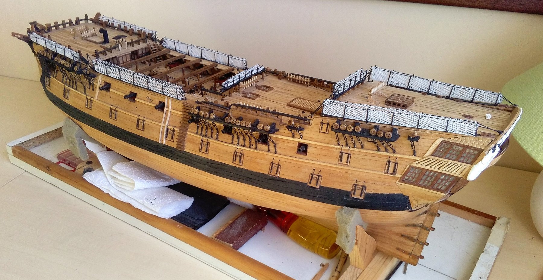
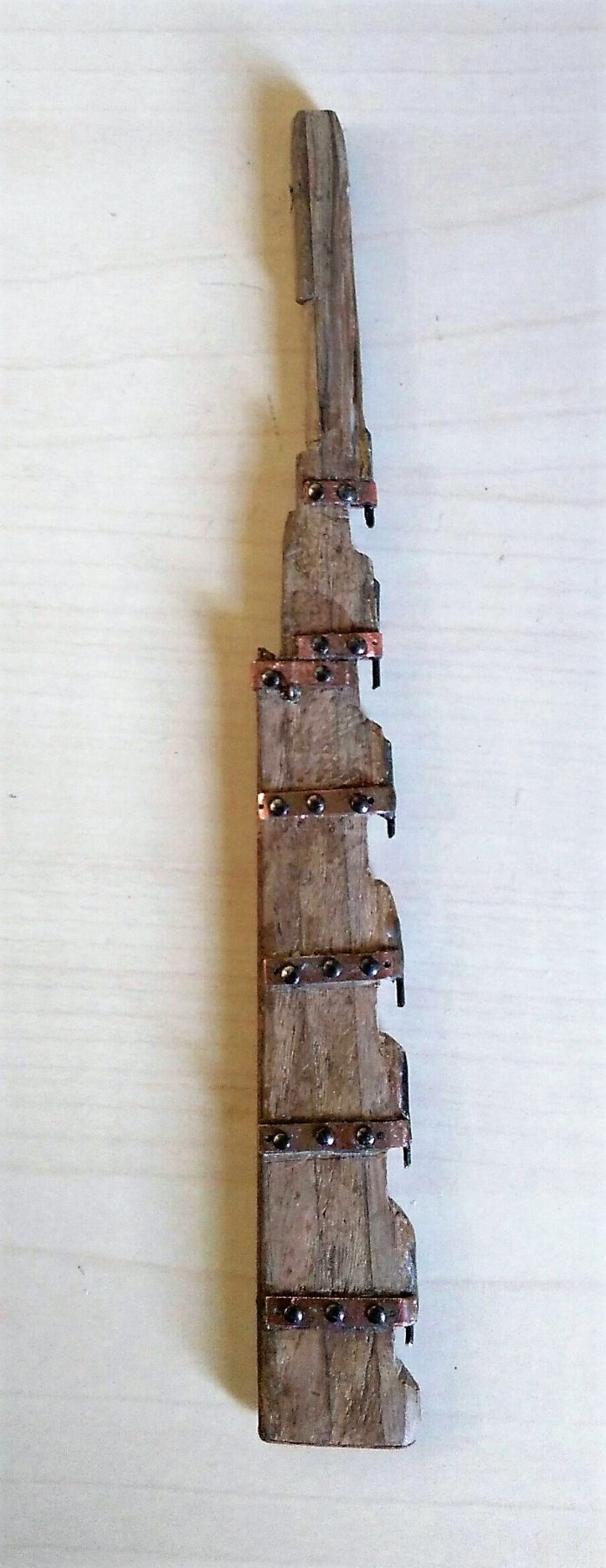
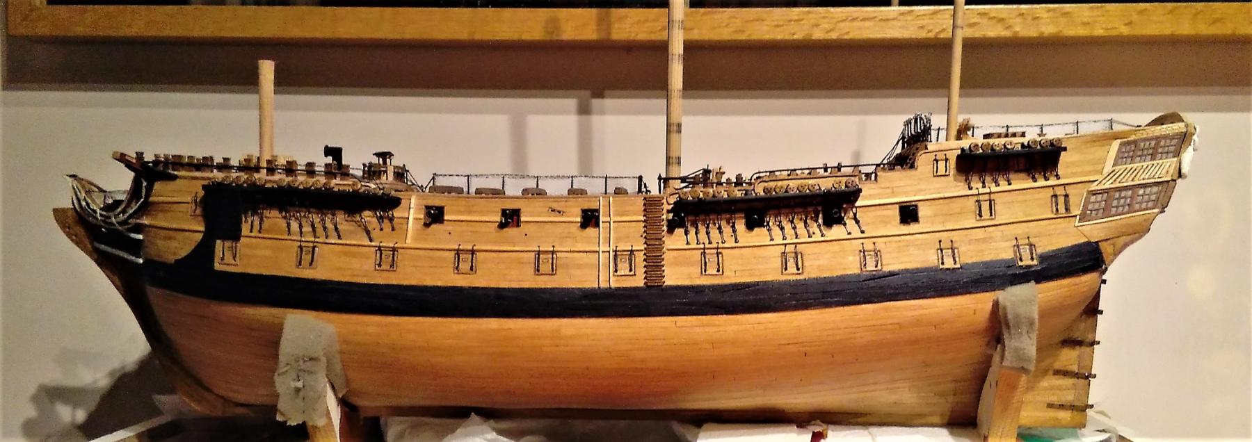
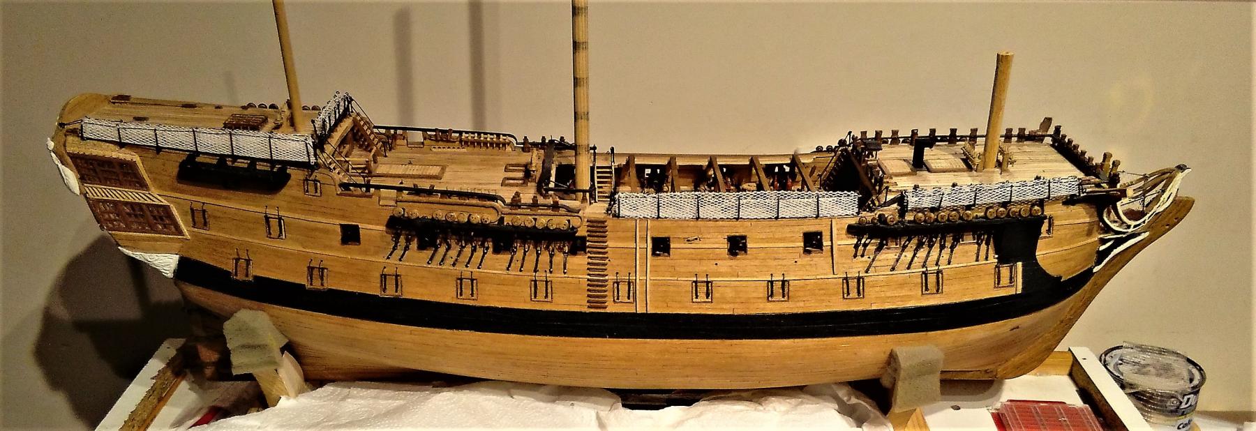
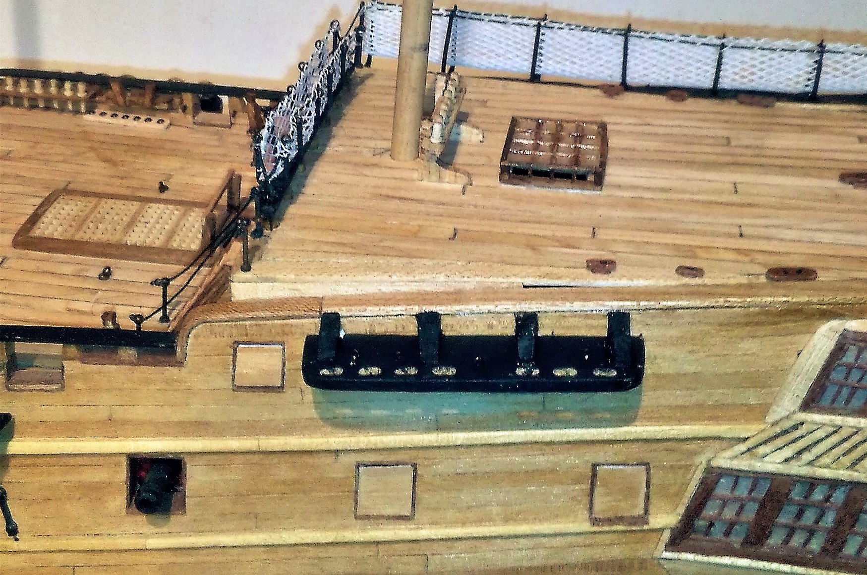
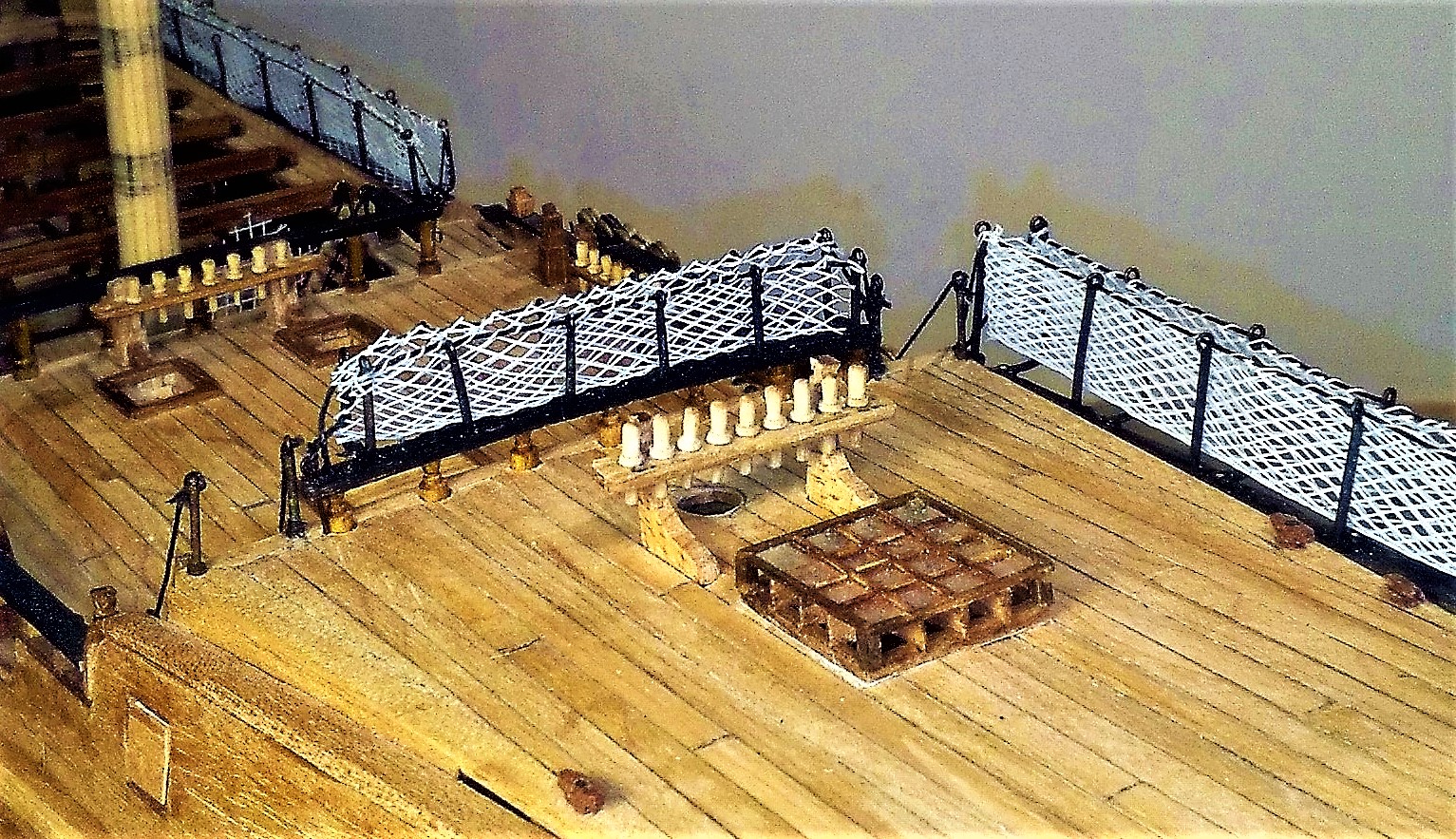
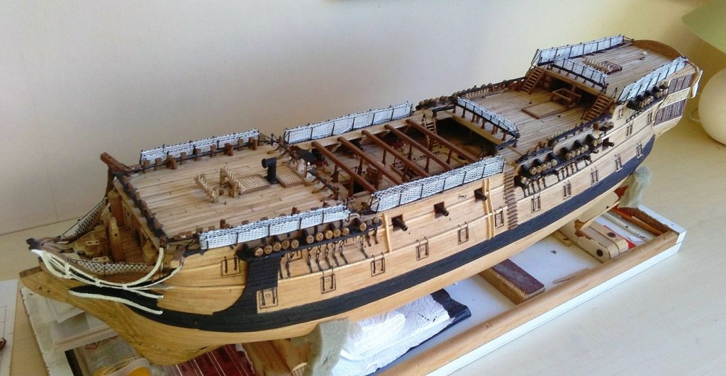
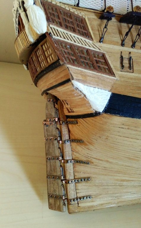
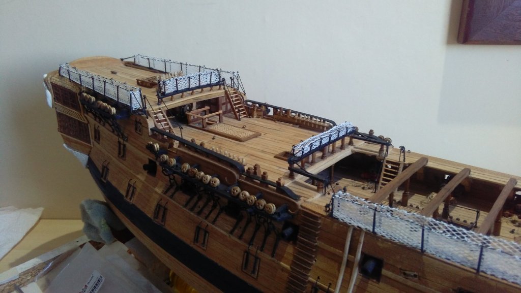
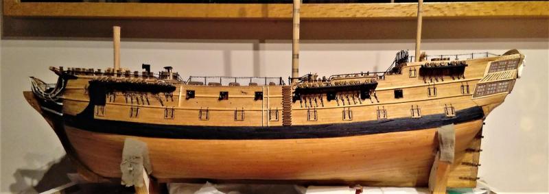
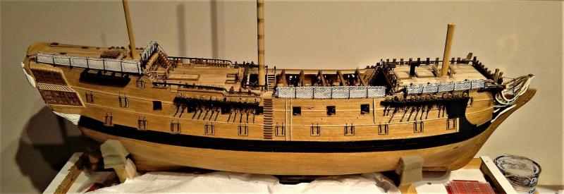
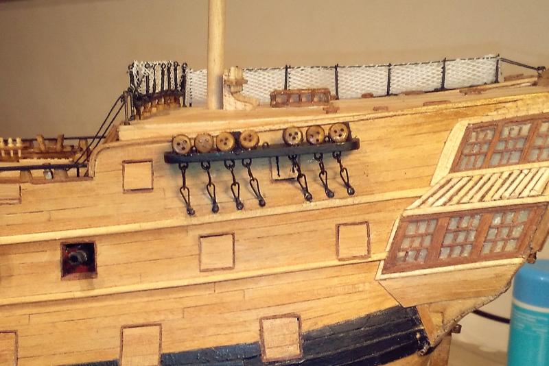
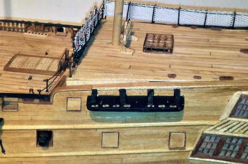
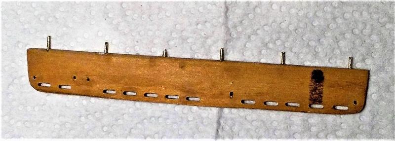
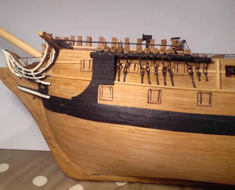
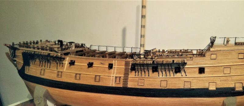
All hammock cranes and netting now in place >>> With the exception of the 2 bow chasers and the 2 quarterdeck guns the deck levels are now virtually complete. Still a few carvings for the stern quarters as well as a few minor 'things' then it will be a completed hull model . . . unless there are any other things I have overlooked ? ? ? The following pics are really 'historic'. Around 4 years ago, when I had eventually finished the hull planking I was keen to see the ship with it's rudder. At that time I didn't consider that I could have made my own rudder irons so went ahead and bought over-the-counter items. While their length was about right, their width was a bit more than was correct for the scale, but as they were all I had, I went ahead and fitted them. I've since often looked at them and wished I could remove them and fit better ones, but as they're glued and nailed on I fear that trying to remove them would make more of a mess of the planking than I would want to attempt to repair - - - so, I'm resigned to living with what I've got >>>


- 257 replies
-
- 13
-

-
Hi Tom, Good progress there. I know what you mean 'picking away at odds and ends' and then not seeing too much for the efforts put in. As for spring yard cleaning - - - I'm not sure, but maybe it's a hobby if you enjoy it! . . . but I DO have good news for you ~~~ ~~~ your "yard fairies" are due to turn up on the same day as my "rigging fairies" !
-
Hi Tom, It's not the elephant that worries me - - - it's the Leopard ! Now I'm going off to repeat "Rigging is only one knot at a time . . . Rigging is only one knot at a time . . . "
-
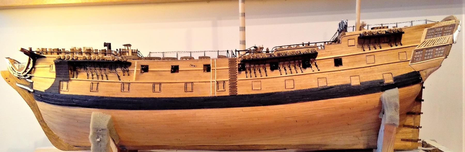
All channels and stools for main and mizzen masts now fitted . . . and hammock cranes & netting for Q/deck rail and port side of poop deck also fitted. Just port side of waist and forecastle await their hammock cranes . . . then it will soon be time to be thinking about the scary rigging for real.
- 257 replies
-
- 11
-
-
Hi Tom, . . . and so the hull planking begins! From what I can see in your photos they look great. What is the thickness of these planks? They look thicker than the ones I used. I used 0.07mm thick planks but I did double planking -- twice the fun! The planks I used were also a little narrower than they probably should have been, so that made it more than twice the fun.
-
Alex ~ I have to say that one day I will be able to build models like you do - - - BUT that will be the day AFTER I am able to fly !!! WOW ! . . . WOW ! . . . WOW !
-
Fukui San: 福井さん, おはようございます. 福井さんのコメントのために非常にありがとう. 私の日本語を許してください ! ジム (Bluto 1790) Popeye ~ thanks for your comments. Yeah . . . I'm no expert! ~ that's why I come here to the forum to see some models built by proper experts! Your friend and arch enemy! . . . Bluto!
-
ふくい さん、 こんいちわ! あなたはとても素敵なビルドをやっています! Hello Fukui, you are doing a very nice build!
-
Tom ~ you're certainly getting on with that build at a great pace -- you'll soon be overtaking me. Are you intending to do the wales as hook and butt as shown on the plan? When doing my wales I attempted to make them as hook and butt ~ but was having too many failures so I copped out a bit and made them as the slightly simpler top and butt. I'm looking at that plan of the running rigging you have pinned up behind your seat and it looks very big compared to my copy. You've obviously had it enlarged substantially -- how many times larger than the original is it? I know that when I look at mine at the small size it is, it is completely bewildering, perhaps it would be a bit less bewildering if viewed at a much larger scale? (The word "scary" could be substituted for the word "bewildering" !!! )
-
Thanks for your comments Mark, and your advice. I had previously thought that I should rig from stem to stern, although I did realise that, in particular, the snaking together of the main stay and the preventer looked like it would be problematic with the shrouds of the foremast in position. So, when I can summon enough courage! . . . I'll make a start at the mizzen mast. You also said -- "Hmm.... what I'm not seeing is anyway to adjust the tension on those lines..." ~~~ Yes, and there are a whole lot of other details that I'm not seeing in that diagram that will make this task more difficult for me. I've been trawling the forum trying to find some build logs that show plenty of details of all aspects of the rigging. Right now, I'm continuing to add a few more items to the bowsprit before it goes in 'the box' to await its turn to meet the ship permanently . . . then I guess I'll just have to get the hull finished with the few missing details before the serious business of rigging begins.
-
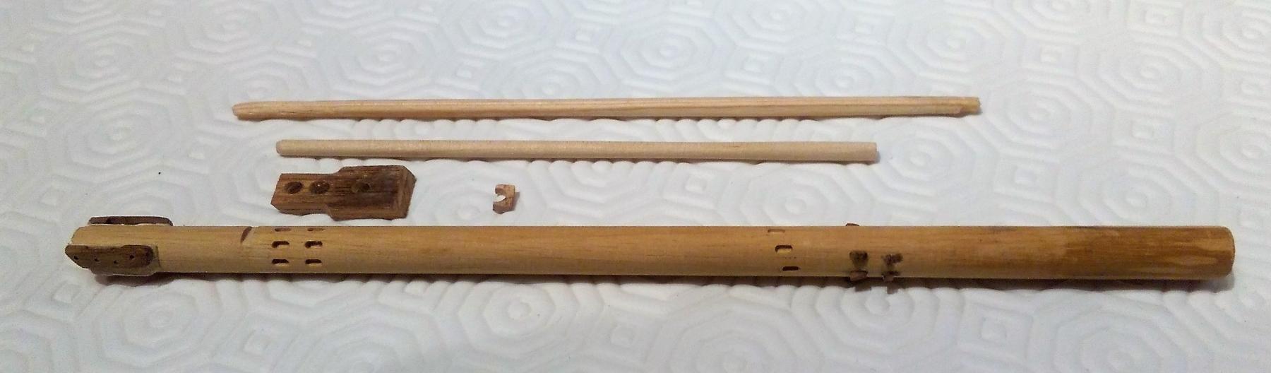
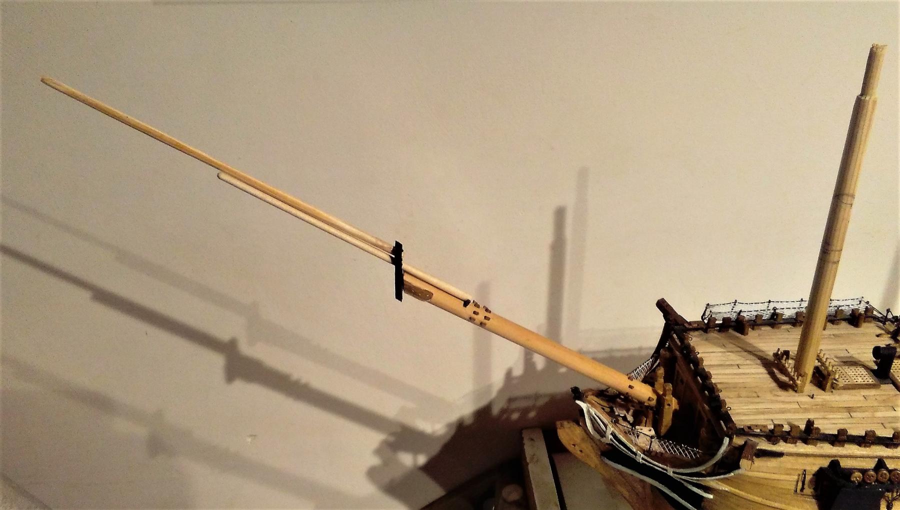
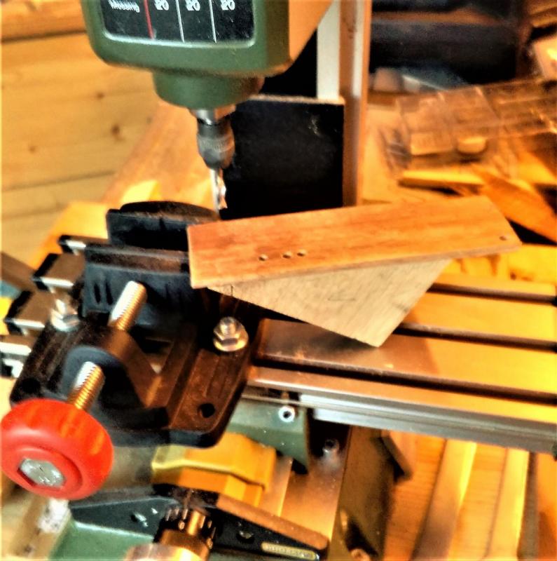
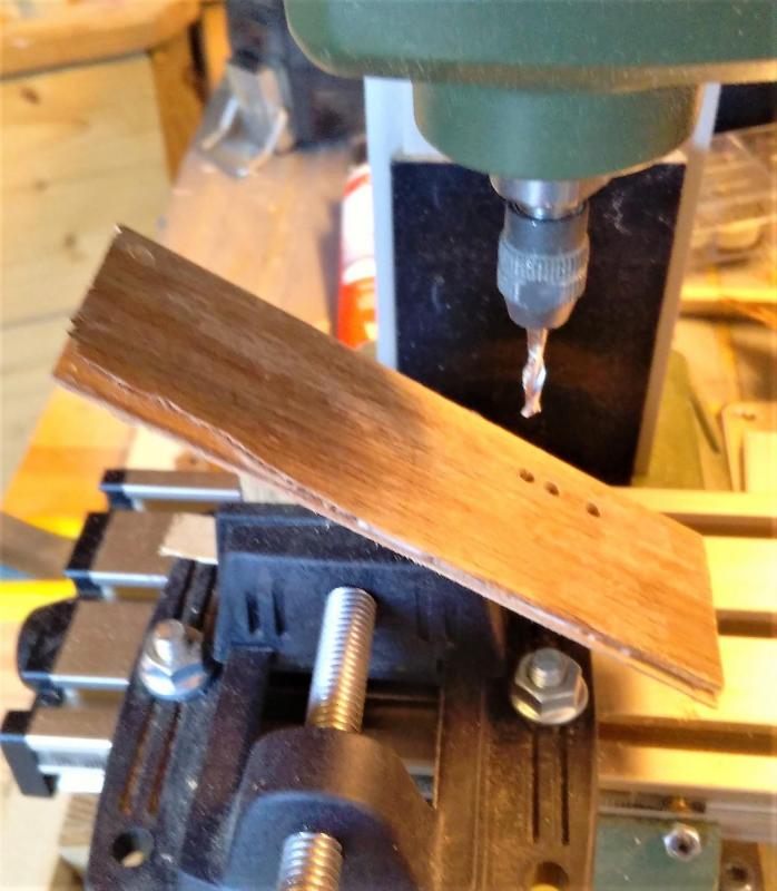
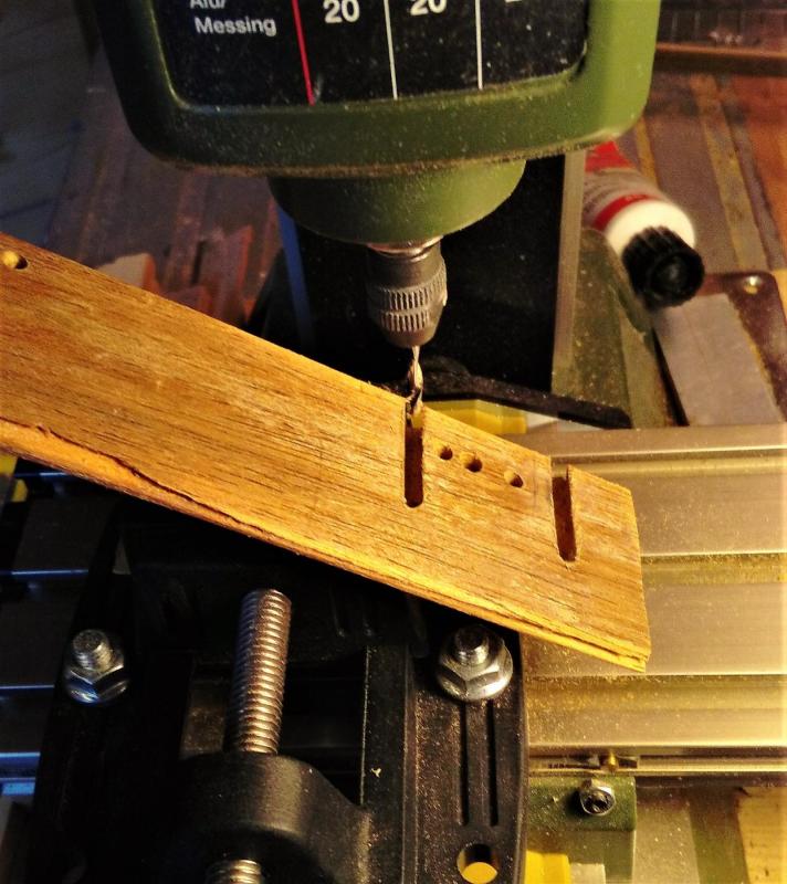
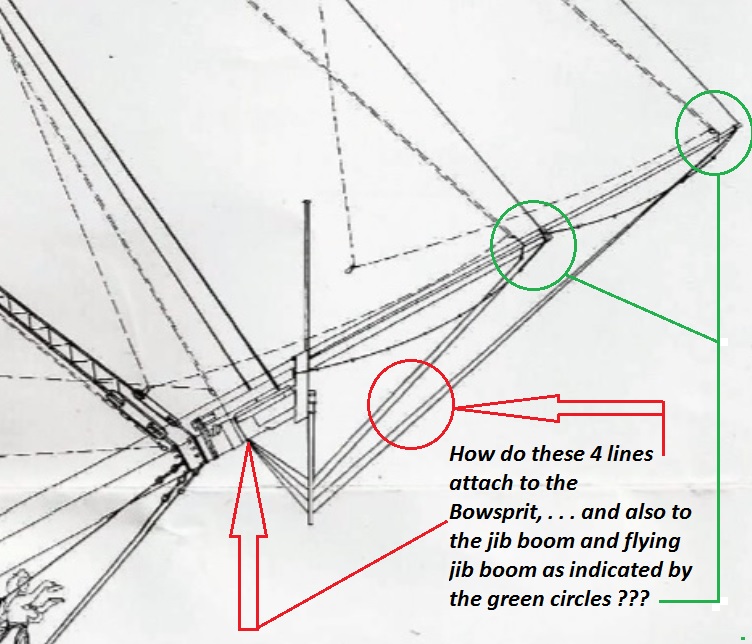
Thanks Tom. Just to get away from trying to create deadeye strops, chainplate links, hammock cranes and the like, I've ventured into another universe . . . "The Rigging". Well, no actual rigging attempted yet but I made a start on the bowsprit. Having no instructions and having no experience of this adventure I have to assume that the bowsprit is the first of the spars to be fitted as the main and foremast stays are fixed there. As well as the bowsprit are the jib boom and a flying jib boom. While the outer end of the bowsprit is 8mm in diameter, the thickest part (inner end) of the jib boom is only 3.5mm and the inner end of the flying jib boom is only 3mm. These 2 outer spars are truly skinny compared to the bowsprit. There are very few details about the masts and rigging contained in the drawings and plans for the ship, and the only single drawing is at half the scale of the plans/drawings for the rest of the ship, so I had to double the dimensions as shown in the drawings. Here's the fore-end of the ship from the one and only diagram of the masts and standing rigging arrangements >>> I used the milling machine for the slots into which the stop cleats will fit. In the pic below the cleats for the main stay and preventer are fitted while the slots still await fitting of the other cleats. Here are the main parts of all those pointy bits at the sharp end >>> . . . and when eventually fitted should look something like this >>> The bowsprit cap required 3 holes drilled at an angle of 30 degrees to correspond with the elevation angle of these spars. I cut a wedge at that angle and spot glued a section of timber at either end on to the wedge, leaving the mid section of the timber unglued for later removal >>> In the vice at the milling machine the cutter took care of drilling the required holes with precision >>> . . . and while the top and bottom edges of the cap also require to be cut at 30 degrees, the mill was used to make these cuts while still in the vice >>> I've already mentioned the lack of detail for the masts and rigging and I foresee a lot of questions being posted here on the forum . . . and here comes the first one now (the question is contained in the pic below >>> I'll have to get back to the other stuff (hammock cranes etc. etc.) before coming back here to start real work on the masts/spars and as all those poles look very scary sticking so far out the front of the ship, they'll be going into 'storage' until the inevitable time comes to get them fitted. (It's going to be very tricky handling the ship when that skinny flying jib boom is eventually fitted!)


-
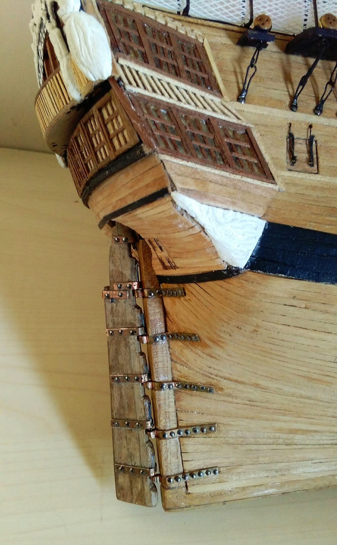
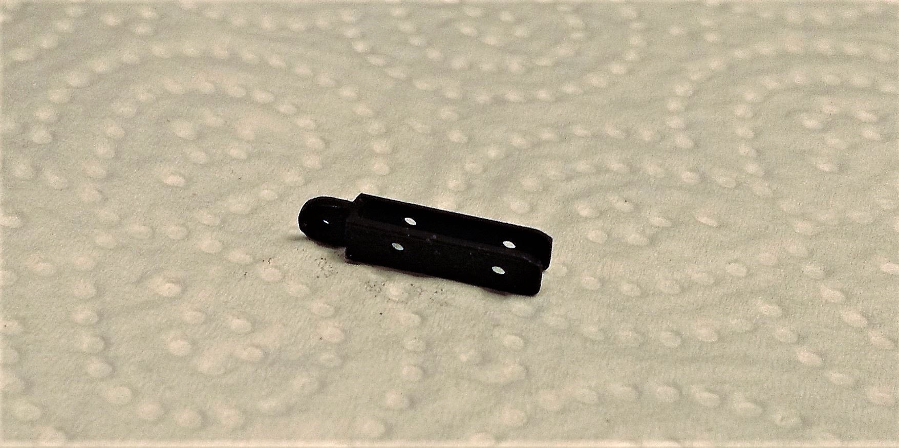
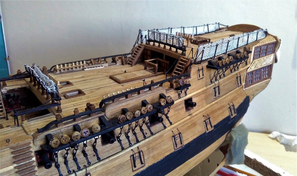
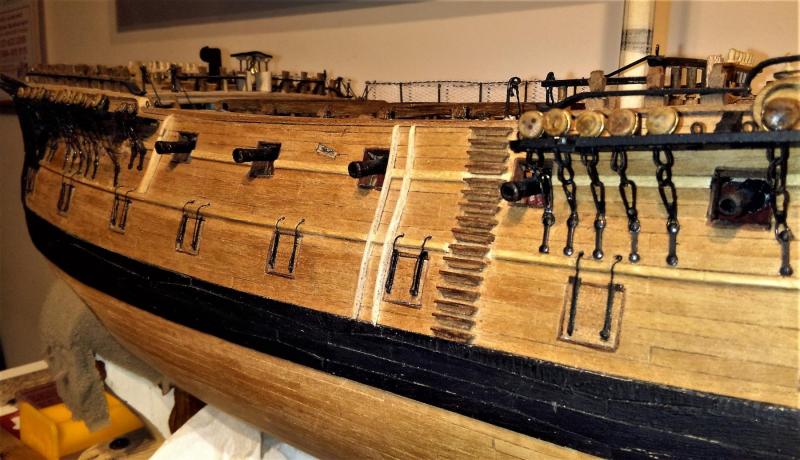
Gunport lid hinges and opening/holding lines fitted on both sides as well as starboard mizzen channel >>> That mizzen channel awaits its deadeyes and chainplates. While it took about 2 minutes to make this posting, doing these hinges, lines and that one channel took the best part of 3 weeks.
-
Tom, Judging by the pace you're getting things done, are you sure you don't have a work force of hundreds building that ship with you! I'm expecting to see you commence the rigging in a few months! I'm watching your build with interest and I'll sure be watching your work on the stern/galleries. I hope you'll be explaining how you do them pesky carvings! I've still got a few bits and pieces to do on the stern of mine. It's well over 6 years since I started my build (with a few lay-off periods) and it's still not even a completed hull model yet . . . and I know the real Leopard from 1790 didn't take anything like that long! . . . oh yeah, that 'life thing' keeps happening . . .
-
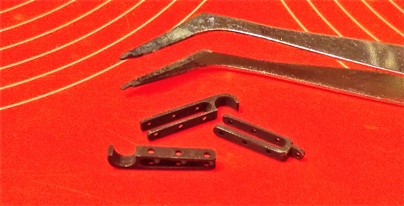
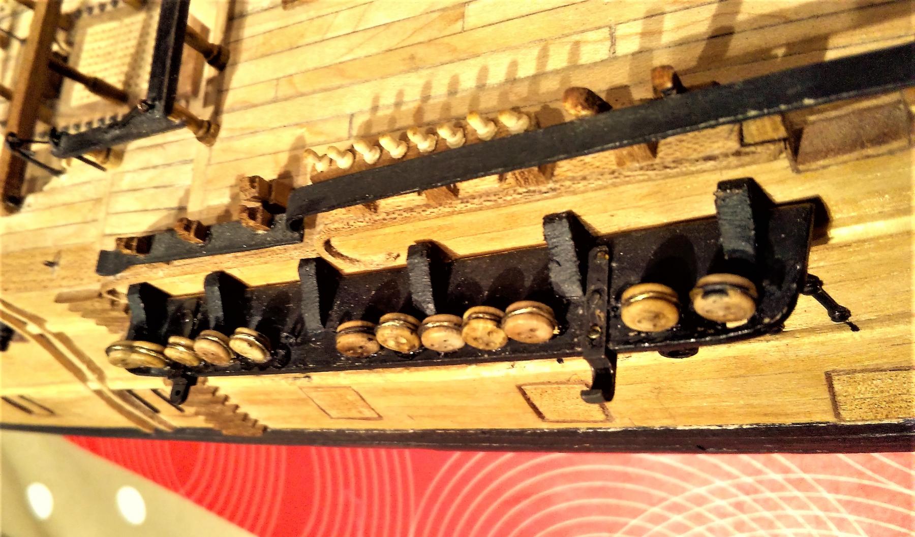
The other 3 brackets >>> Blackened >>> Two fitted to the port main channel >>> Port mizzen channel >>> With the exception of the stool channels, all port side channels in place >>> Some 'fake' non-functioning gunport lid hinges have been attached for a very long time. It's about time to be getting the rest fitted. Had a go at fitting some opening ropes for the lids >>>


- 257 replies
-
- 11
-
-
Tom, if you were to check back near the beginning of my log I stated there that I would have preferred to have built in a larger scale (1:64 or better still 1:48) but because of final space requirements for display chose to go with 1:80. There have been certain parts of the build that have proved a bit difficult for me due to the small scale, but, having said that, I've discovered that as I've progressed there have been some projects that I HAVE been able to undertake and with which I've had reasonable success. Plunging in at the deep end with my first build has certainly thrown up some challenges . . . it has also shown up my weaknesses when I look at so many of the "super builds" here on the forum!
-
Hi Tom, Great work on these gun carriages and also the ladder, grates and pump cisterns in your earlier post (29 December). I have to say that when I saw your pump cisterns it sent me scurrying back to the book as I imagined that I had somehow missed creating these for my model. I found the page with the drawing and gulped a bit when I saw the pumps in situ behind the main mast. Thinking "how am I going to fit these pumps now that my model is fairly close to being a completed hull model?" ~~~ then after a couple of minutes I realised that the pumps are on the lower gun deck which, on my model is virtually obscured from view and I remembered that in the early days of the build I made the decision not to include things that wouldn't be seen after completion. (It's now so long since I looked at these drawings that I've forgotten some of the stuff that's in there.) Now, will you please stop making those scary postings here !!!
-
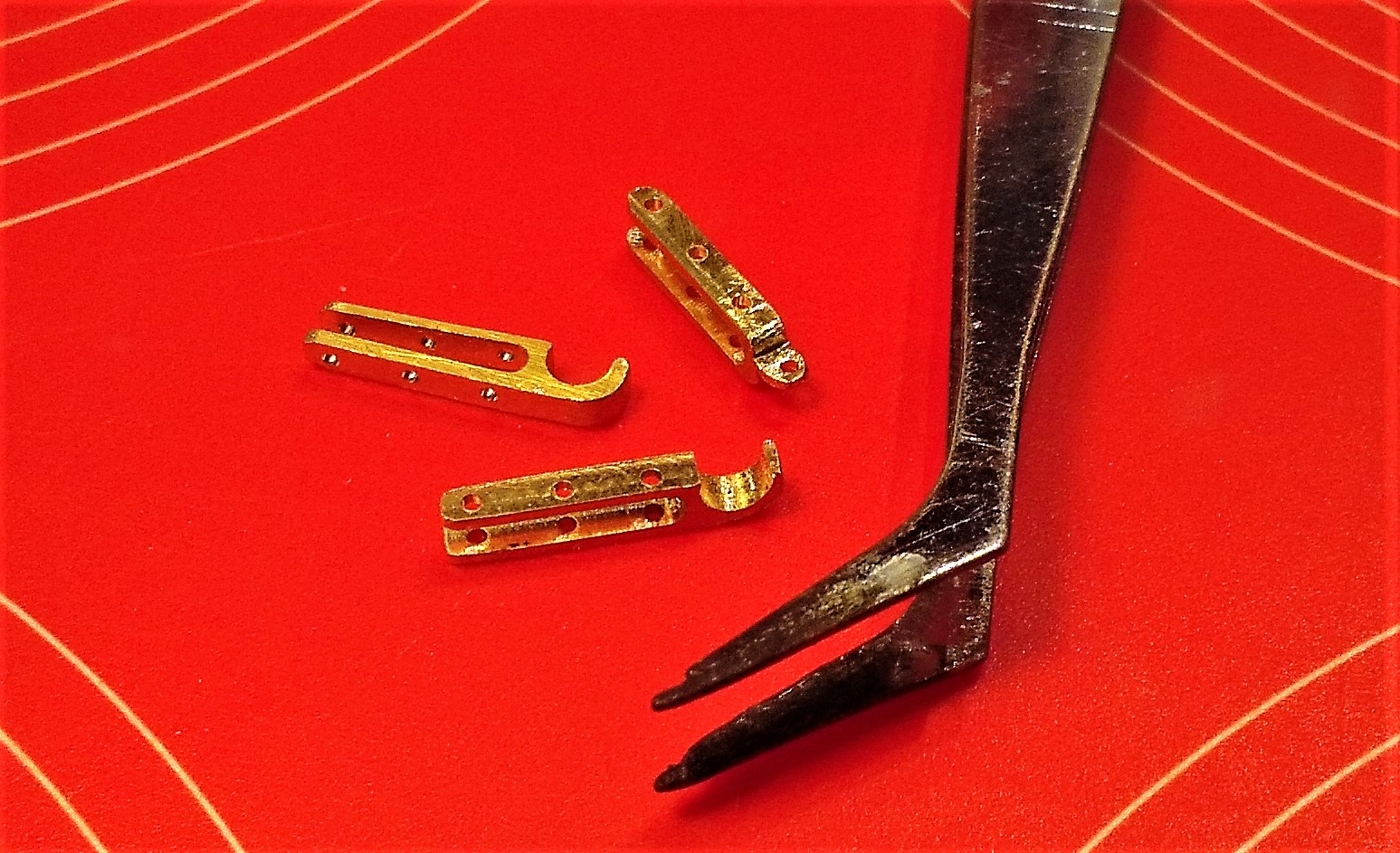
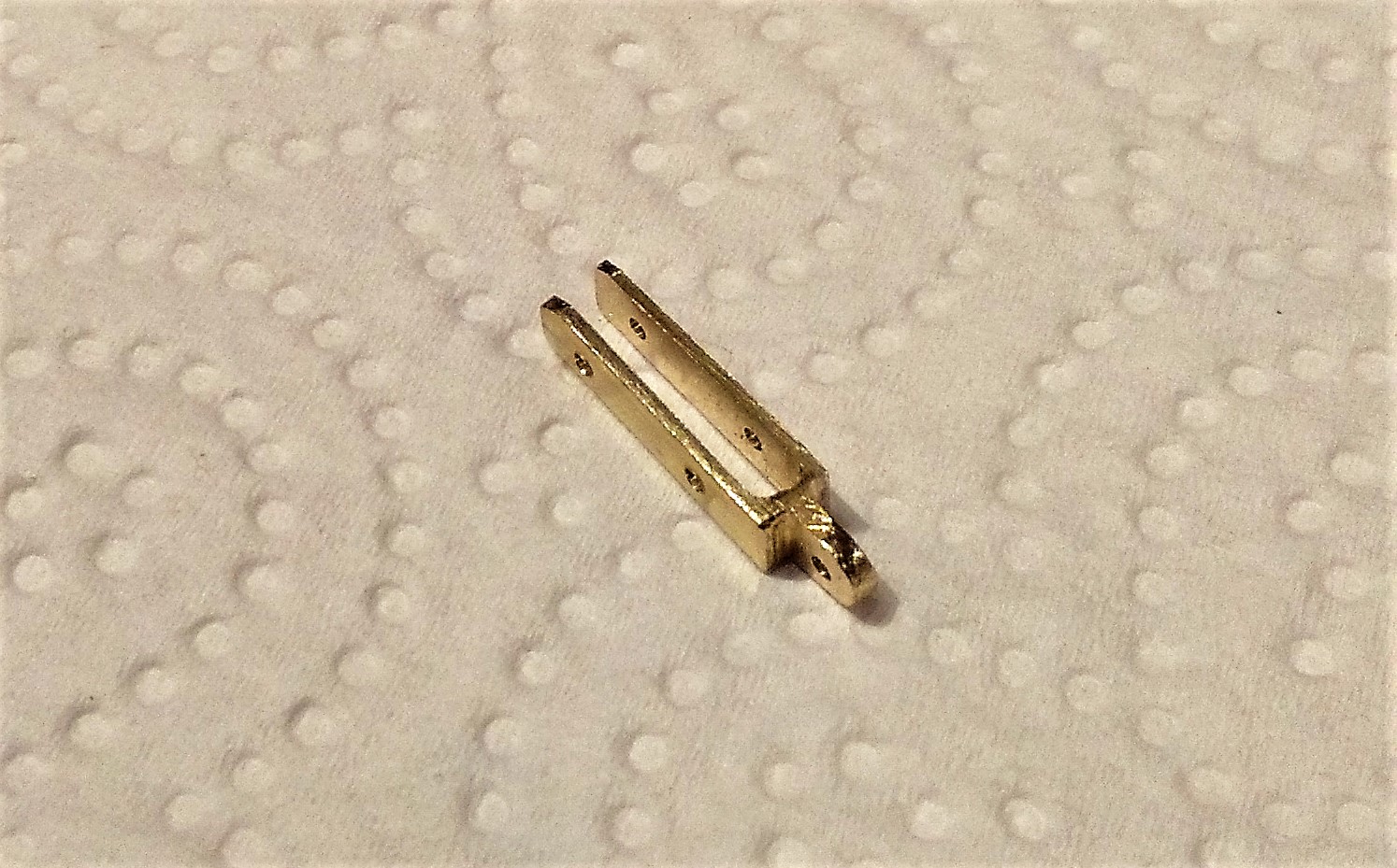
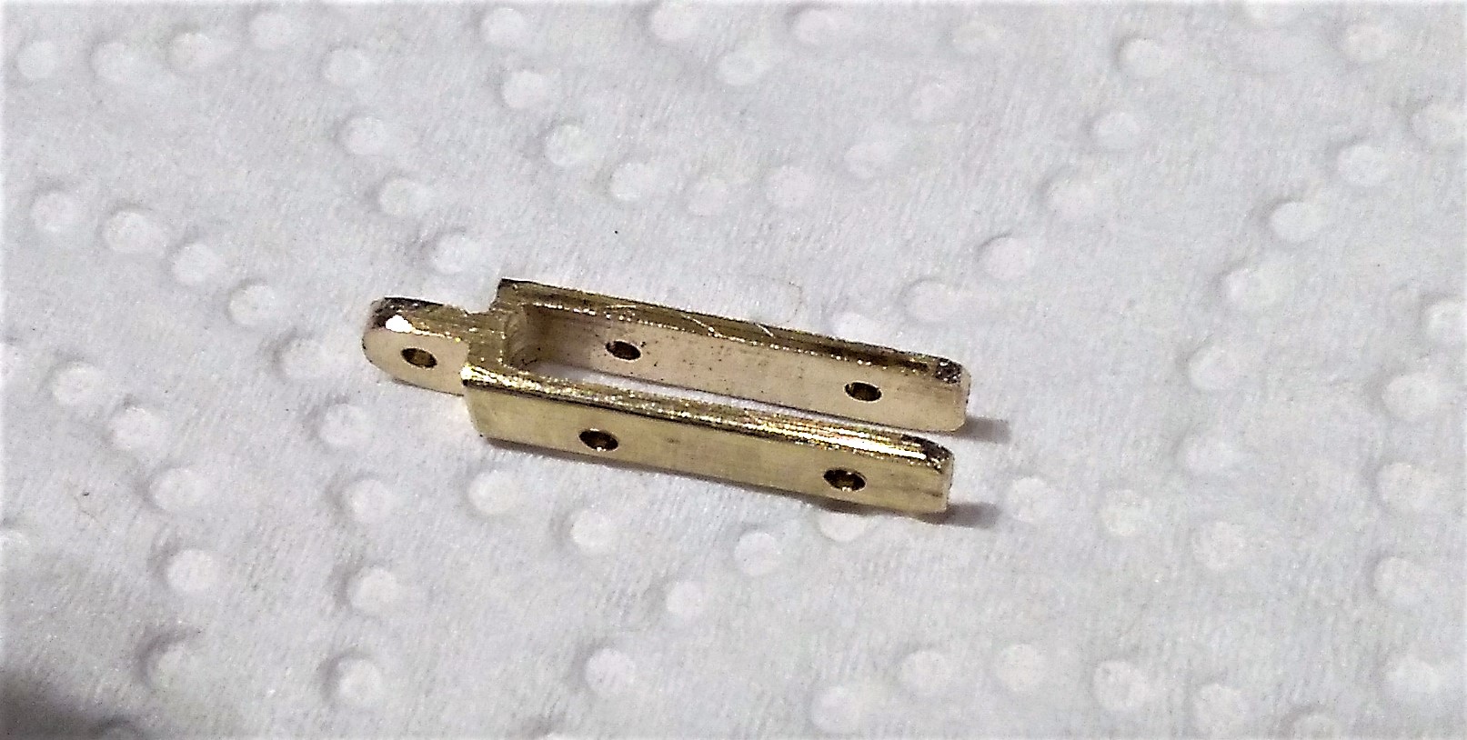
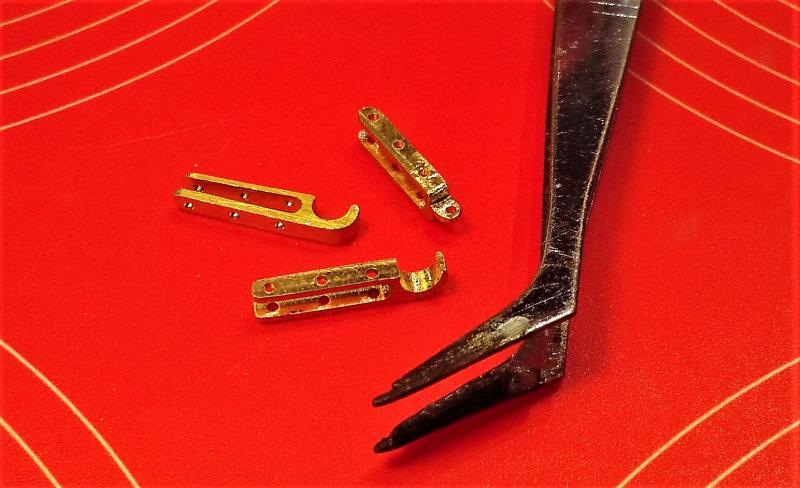
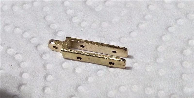
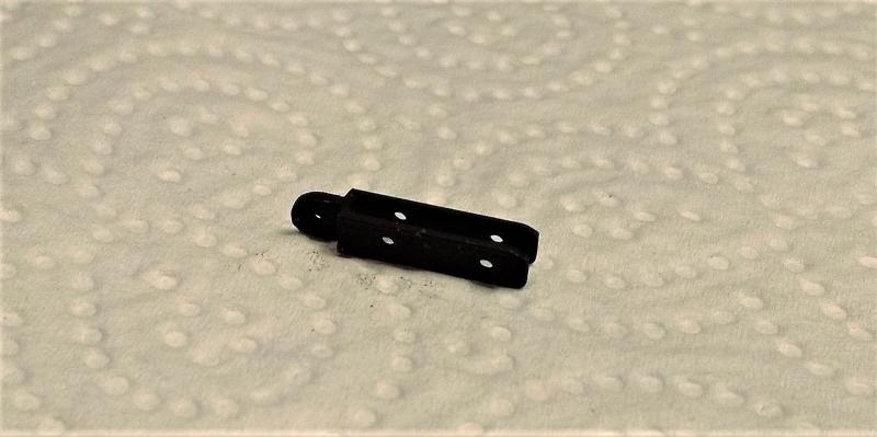
Thanks for the comments, Tom and fmartins. Start made on the port side mizzen channel. Unlike the main and fore channels there are no plates that anchor the bottom chain of the chainplates, instead the bottom chain link is nailed directly to the hull. Here are the 7 lower chainlinks before soldering >>> . . . and after soldering >>> I don't have much experience of soldering (as you've probably guessed!) and I find it difficult at this scale not to get too much solder on and a little bit of filing is required to knock off the lumpiness. The channel awaits its chains >>> While I've used the milling machine on a few wooden projects for the ship I've never used it on metal. So, today I had a attempt on a piece of brass. I find it's not possible to obtain brass in the dimensions I required from ANY craft or model shops I have tried (even Cornwall Model Boats don't stock it). I wanted something with a thickness of around 3mm and a width of at least 6mm to allow me to have a go at milling what I had in mind. I found a metal supplier on ebay and got what I wanted within 2 days. I got a piece 12 ins X 1 in X 1/8in (300mm X 25mm X 3mm). Now, I don't know the official name for the parts I want to mill, but hopefully someone may come up with the answer when one of the parts is seen. They are brackets that attach to the main channel; the forward one has a hole in its outer end (in the pictures below) and the rear one has a "half-moon" shaped holding bracket at its outer end. Here are a few pics of the forward bracket >>> . . . and with a dose of the black stuff (I've read posts by others who haven't had much success with blackening brass or copper, but I've always had excellent results with Carrs Metal Black for Brass -- it's equally good on copper as well.) >>>

-
Hi Remco ~ it has been a very l-o-n-g time but I'm sure there are plenty like me who are keen to be seeing your updates. I'm glad to know that I'm not the only one for whom hull planking isn't a favourite activity. . . . and I'm intrigued to find out what 'cheating' in a 'Remco style' could be! - - - I know what my style of cheating is, but I don't think the words 'cheating' and 'Remco' should appear in the same sentence!
- 1,215 replies
-
- 4
-
-
- sloop
- kingfisher
- (and 1 more)
-
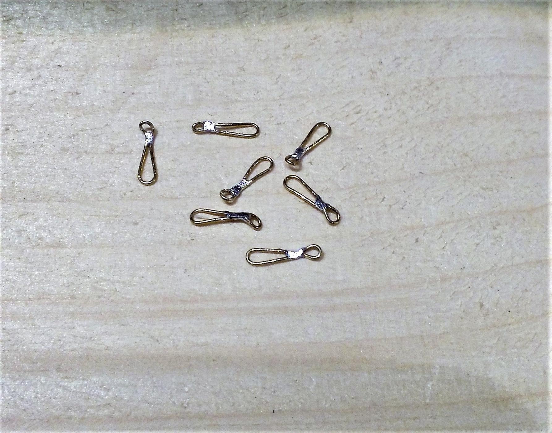
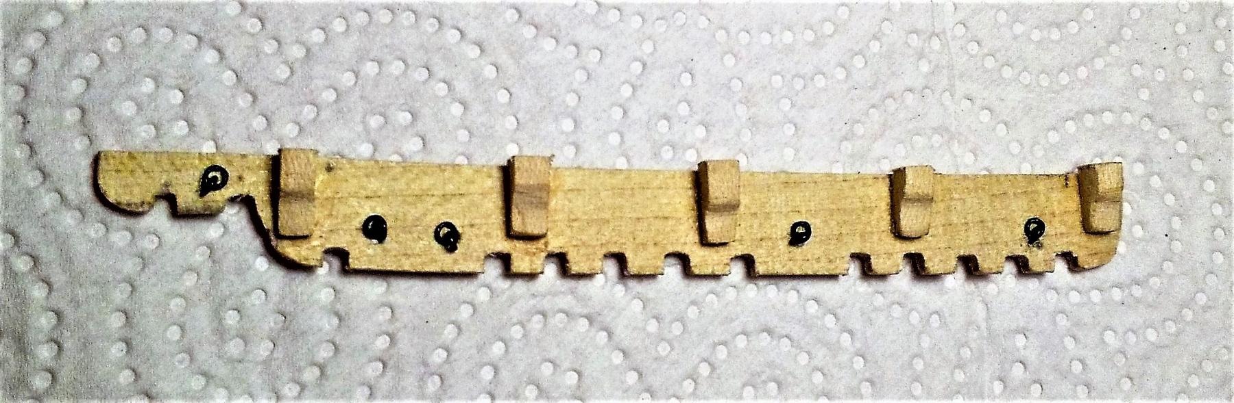
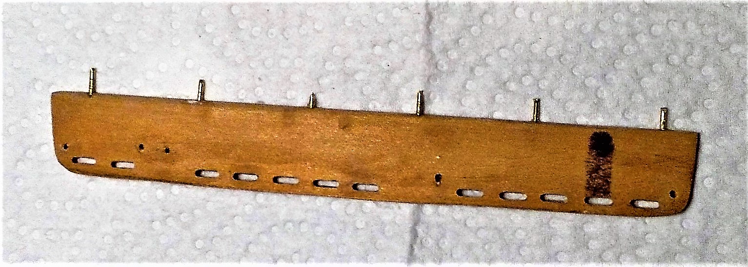
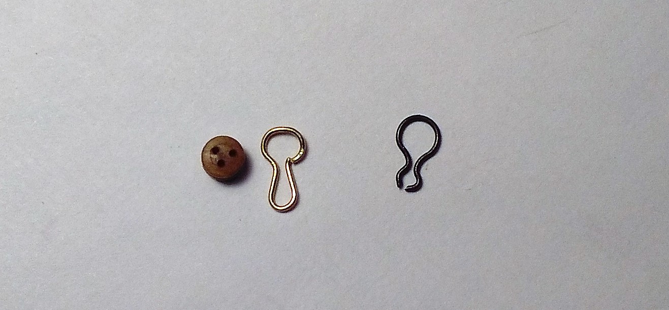
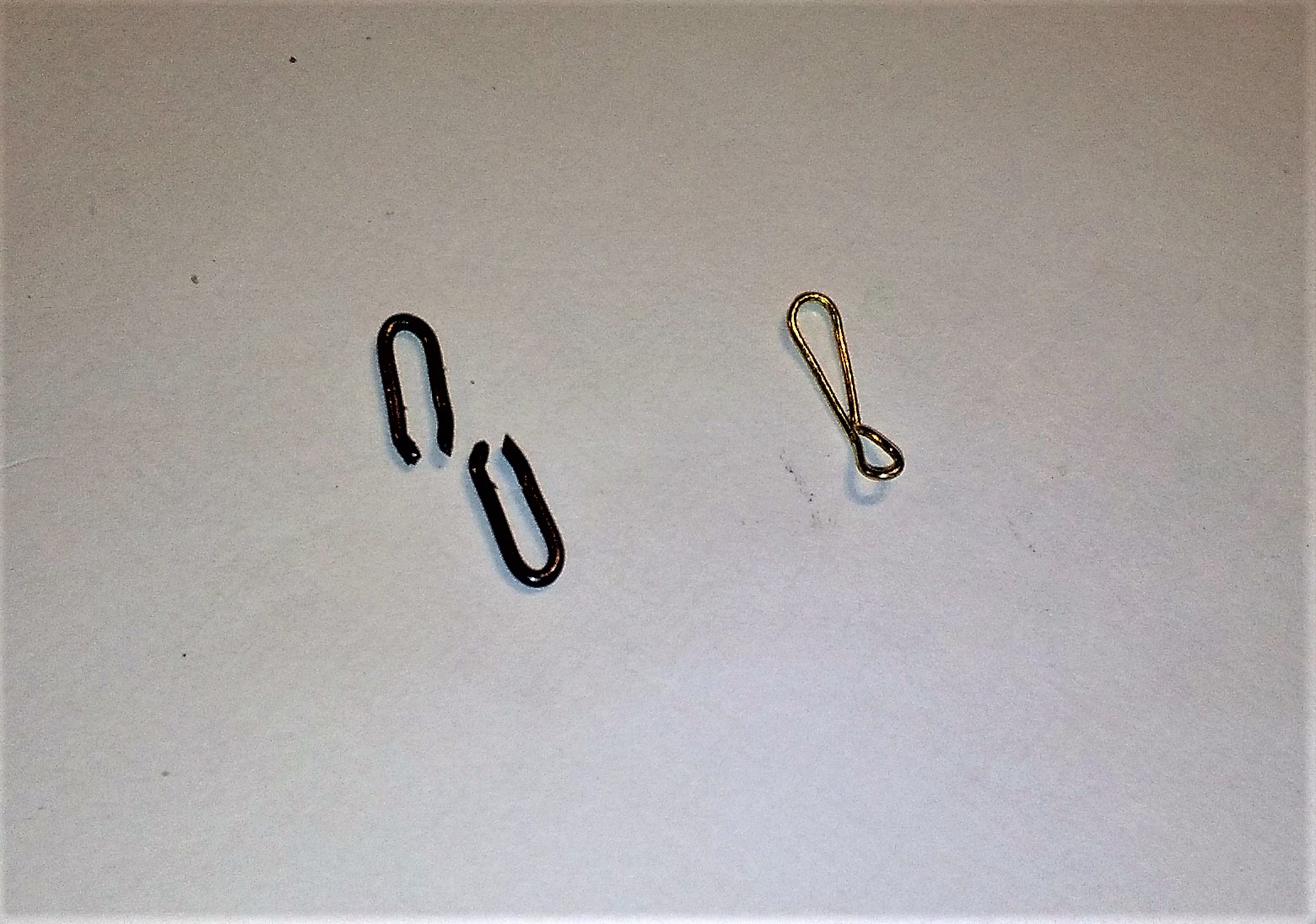
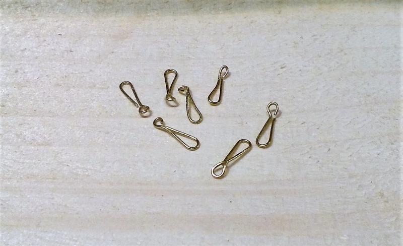
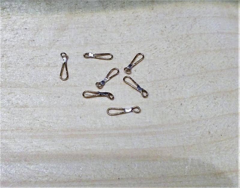
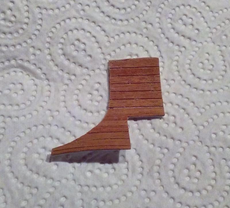
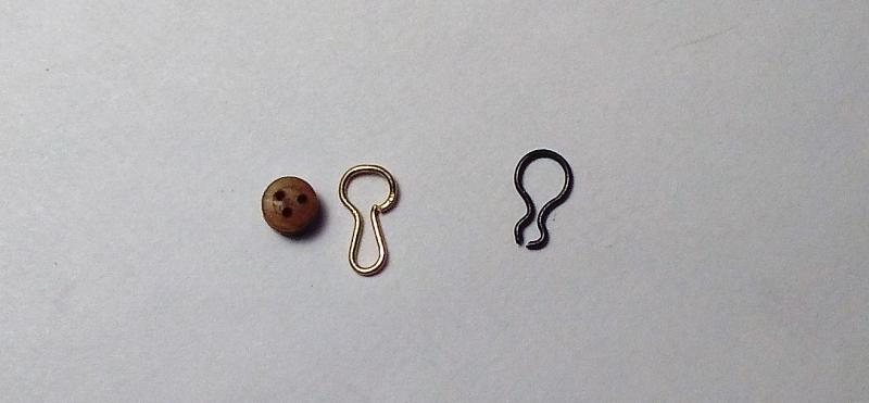
It's over 10 weeks since I last posted some 'progress' and although I HAVE been busy on the ship, there isn't a lot to show for it. I finished the mizzen sheet bitts and pinrail (after a few 're-dos'!) >>> I had already fitted the starboard fore channel which I had made more than 3 years ago as a diversion from the tedium of the never-ending hull planking. When I made that channel I made it like this >>> I made 'notches' for each of the deadeye strops then glued a thin strip of wood on to the outside edge (not shown in the photo above). That was long before I bought a milling machine, so with the channels I'm now making, I'm using the machine to mill a slot for each of the strops and now there is no need to glue anything on. >>> The photo above shows both main channels. The lower one is a blank before milling and roughing to shape. I spot glued the paper plan as a guide to milling and rough cutting. The upper channel has been milled and is cut roughly to close to its' final shape. (The dark mark on the wood means nothing and just happened to be there - it won't be seen after the wood is blackened.) The first channel I previously fitted was merely glued on, and while it has proved to be firm in its' position, I decided to give the others some extra grip. I drilled the channels and fitted 0.8mm brass wire. >>> The port side billboard >>> . . . and fitted along with the port fore channel. >>> When I fitted that channel I was still using the cut-out notches (for the strops) and I was also using store bought strops and chain links. I'm not happy with this channel and right now it awaits being re-done with different chain links as well as different chainplates. First, the store bought strops don't work with the milled slots as their lower 'loops' aren't long enough to pick up the topmost chain link. (These strops only worked when I was able to fit the topmost link BEFORE fitting the deadeye/strop to the channel.) In any case, these strops had their opening right at the bottom of the lower 'loop' and I found a little difficulty in getting them to stay closed properly when a little pressure was put on them. So, with 0.5mm (1/50 inch) brass wire I decided to try to make my own strops with the opening in a different place >>> Likewise with the store bought chain links ~ their openings are also at the bottom (or top, depending on which way they're used), so I also tried to make my own with their opening at a different place >>> Here's the port main channel with the scratch made strops and chain links. It's not perfect but I'm happier with it than that fore channel >>> Now, why didn't anyone tell me what a frustrating and time-consuming job it would be to fit the channels ? !!! Still got both mizzen channels, the main and mizzen stool channels . . . and re-do the other stuff that needs re-doing . . . . .


- 257 replies
-
- 11
-