
TJM
-
Posts
362 -
Joined
-
Last visited
Content Type
Profiles
Forums
Gallery
Events
Everything posted by TJM
-
CAD file 3D printing question
TJM replied to CPDDET's topic in CAD and 3D Modelling/Drafting Plans with Software
Also, be sure not to scale the supports, at least if you do resin 3D printing. They will quickly become too small and the print will fail as the (weak) supports are ripped off the piece. A print service should be able to re-scale and add new supports that fits the new scale. -
Very interested to follow this build. I have version 2 of this kit for a (far...) future project, and while I understand that there are significant differences between version 2 and 3, especially on the rigging, it will still be a very nice reference to have your log to look into!
-
Hi B.E. I understand your caution - I am a chemist, so I am biased 😉. I must say I actually like your results, especially the lower square example. But I would much prefer to use a few select chemicals than the all natural route to achieve the result!! But your untreated hull also looks great as is - I am very much enjoying following your build!
- 332 replies
-
- 3
-

-
- Harpy
- Vanguard Models
- (and 1 more)
-
Hi B.E. Very interesting tests with the copper patina. I have heard that a water solution of 2% urea with a few drops of ammonia will make a good patina. I guess this will emulate the 'natural' approach , but is perhaps more controlled and can be tuned in terms of strength of the solution and ratio between urea and ammonia. I will try that myself when I get the chance! BR TJM
-
Fantastic! 👏
-
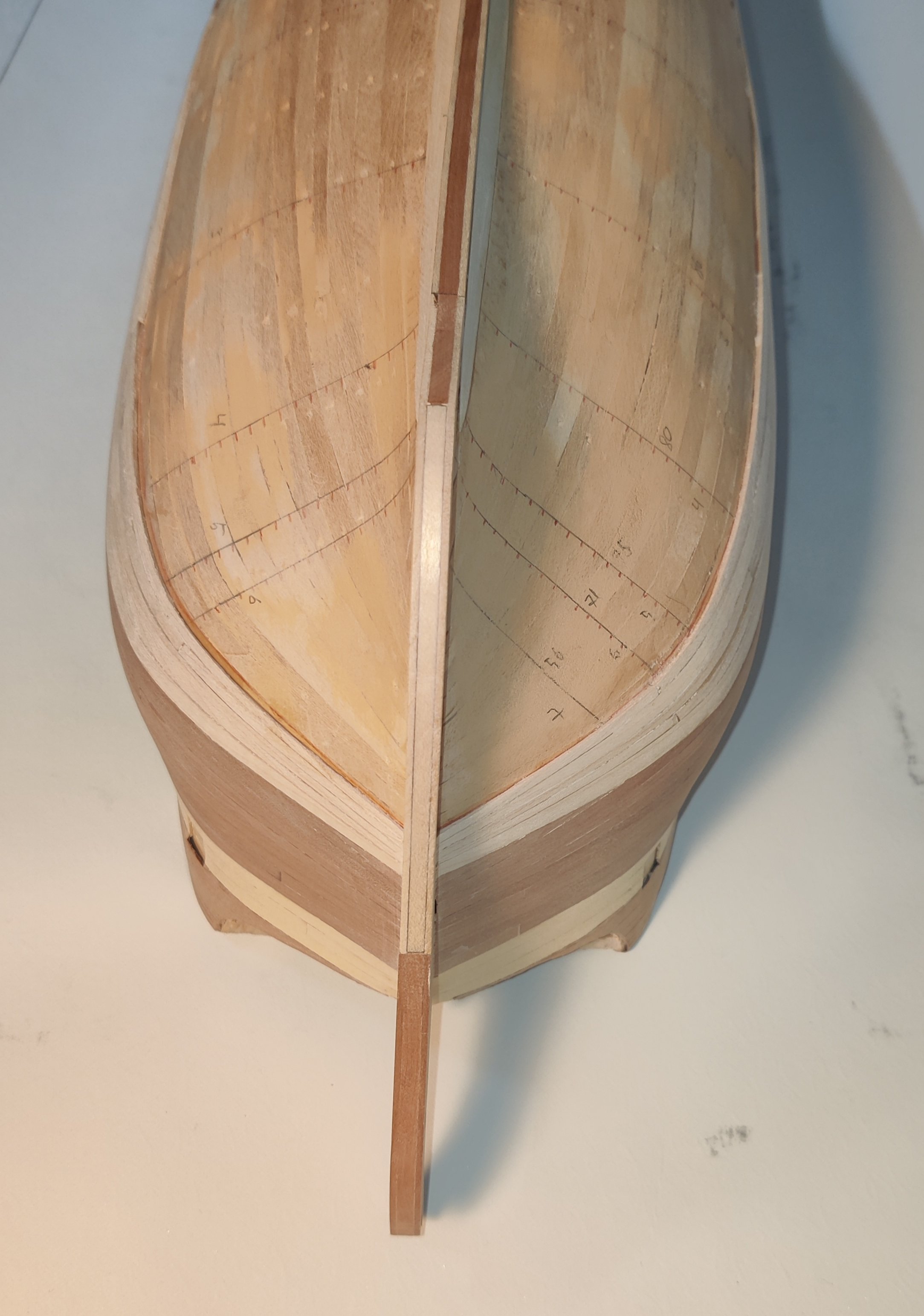
Thank you Matthias. I do pre bend every plank in all directions needed, but I often snap one or bend too much, or mess up the bevel at the edge. I did the same on Flirt, but the planks on that ran much more naturally so it was much quicker. It is just my silly idea to use another wood below the waterline and the way I ended up making those planks that is causing me trouble now! I just may not do it this way on future projects 😅.
-
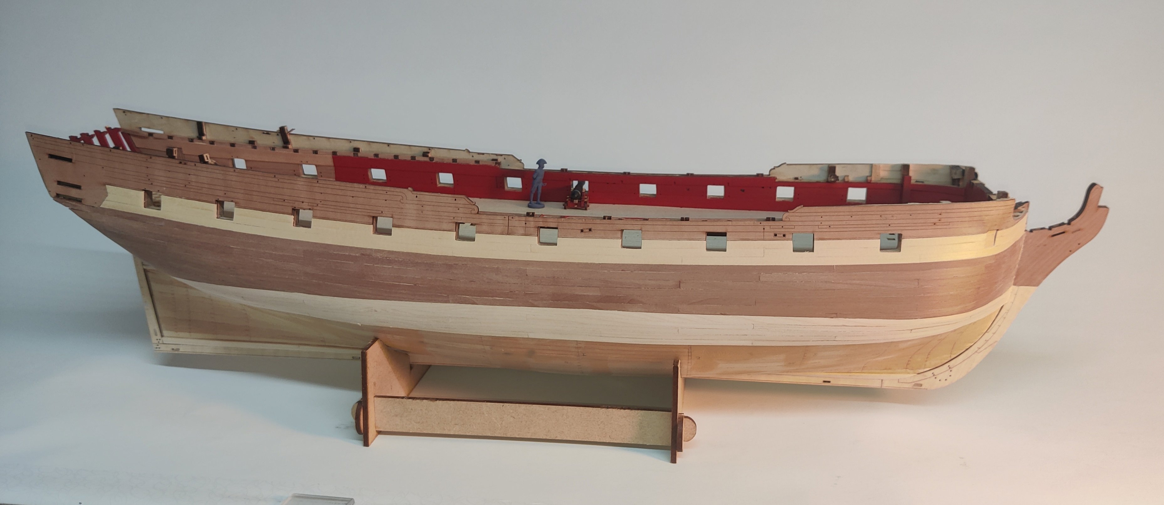
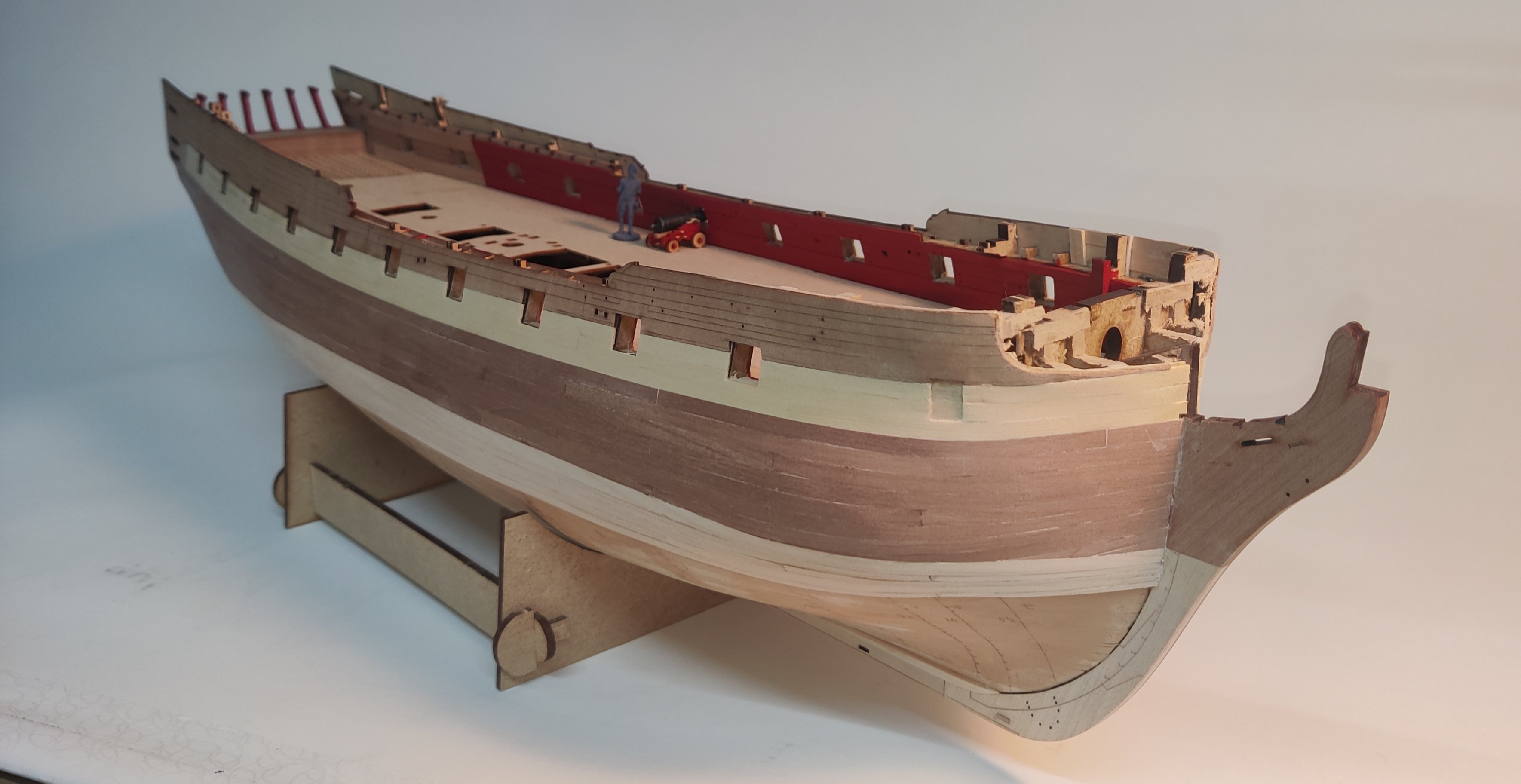
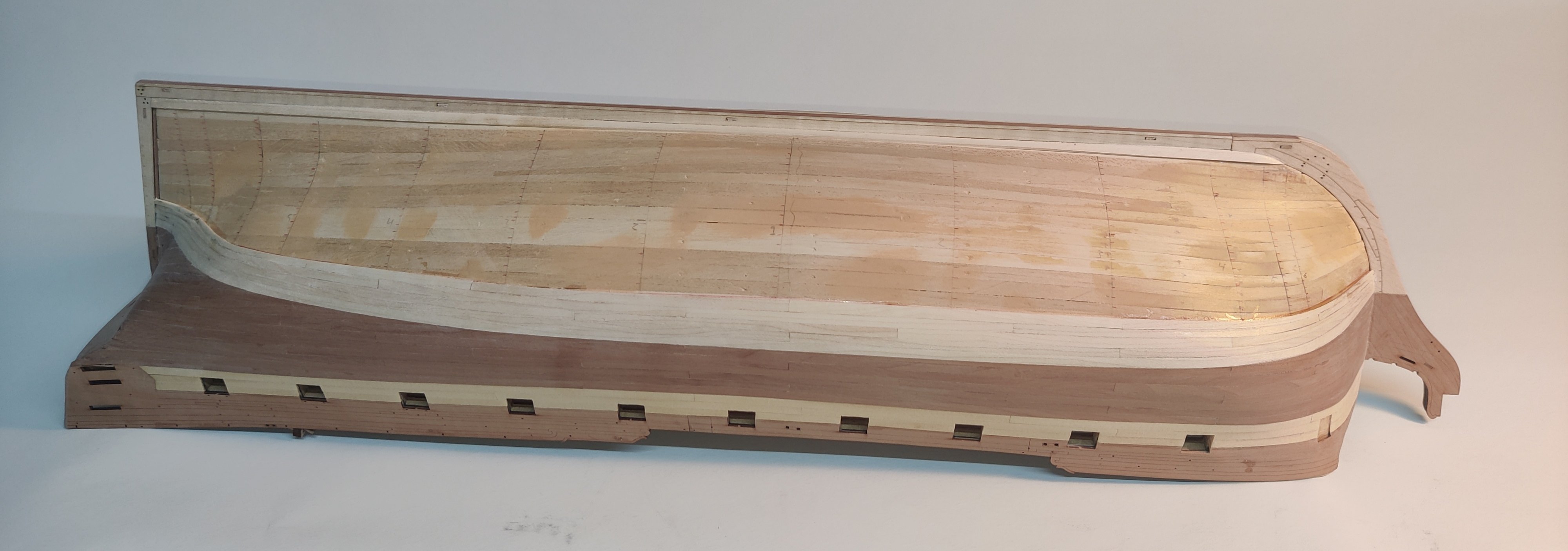
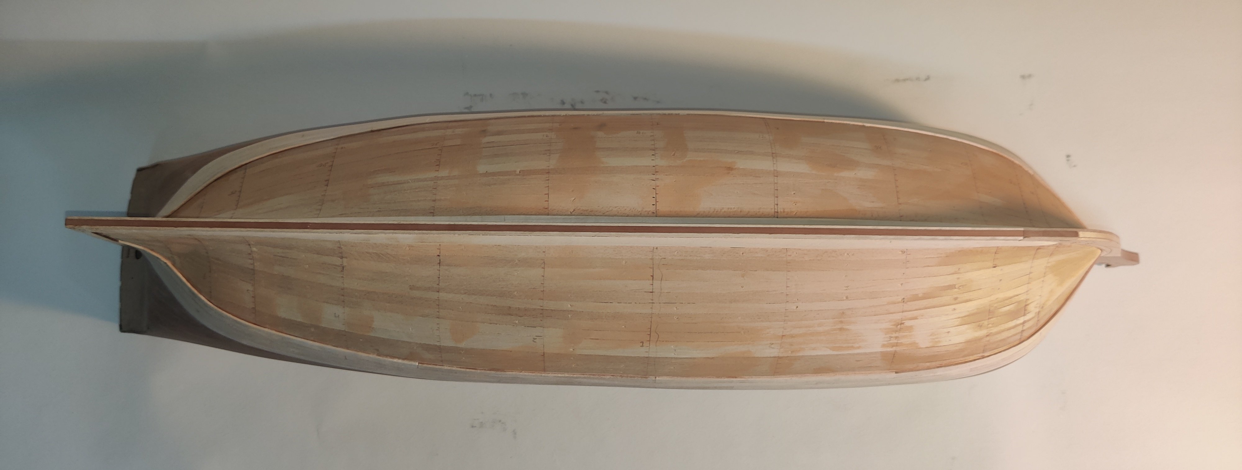
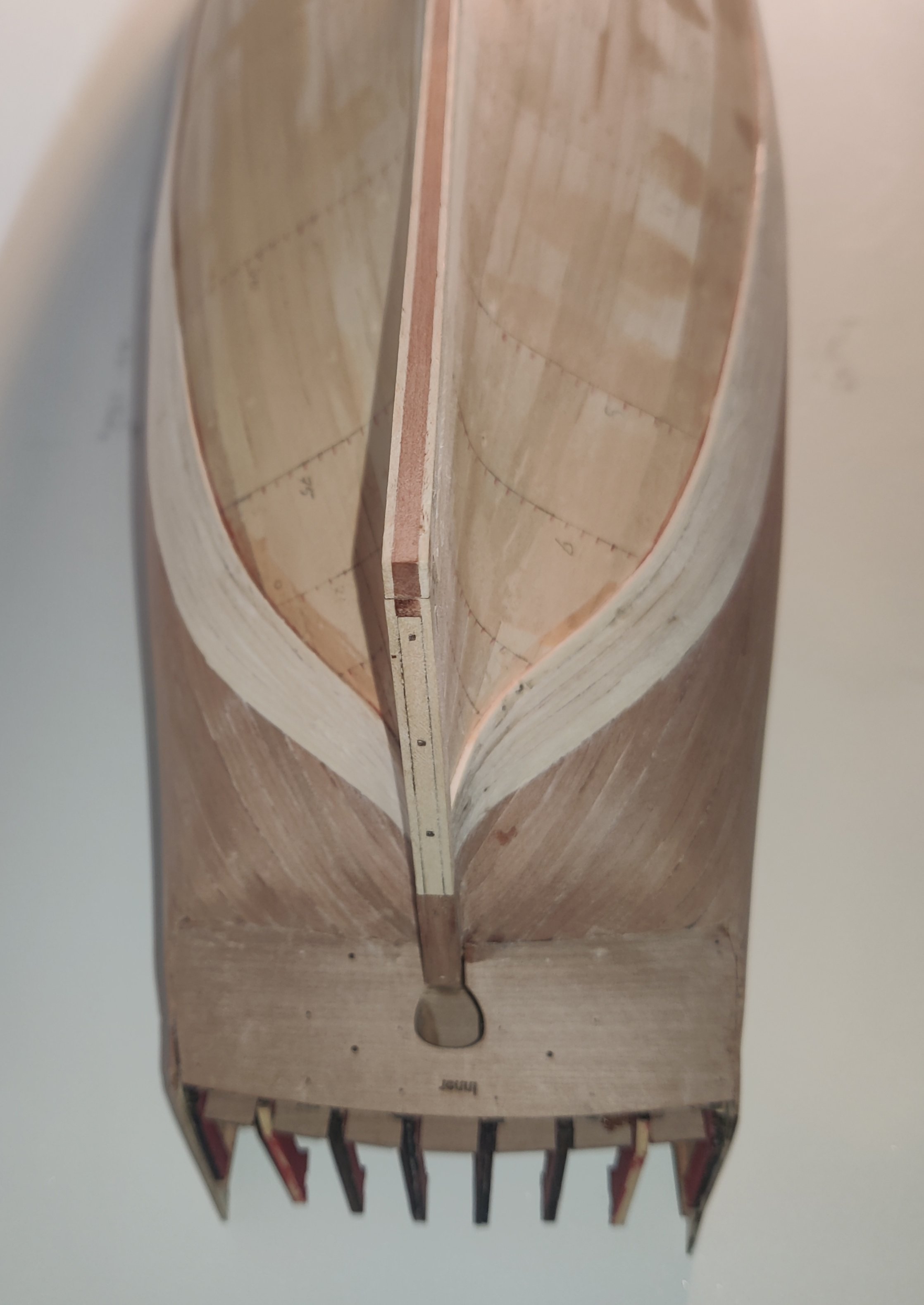
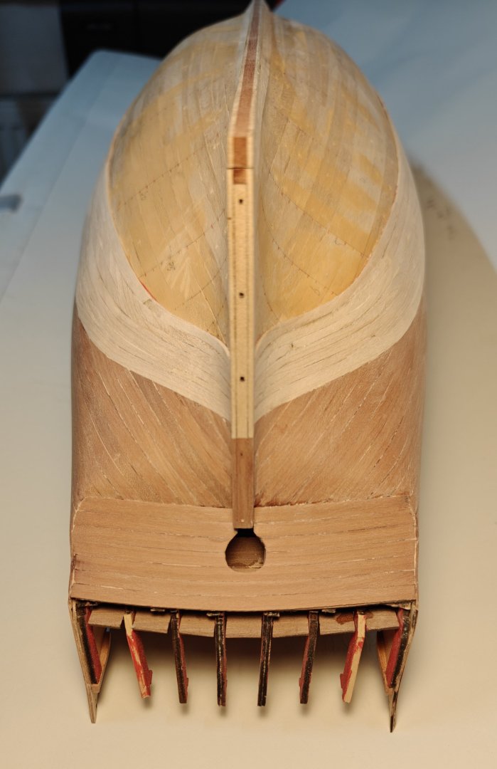
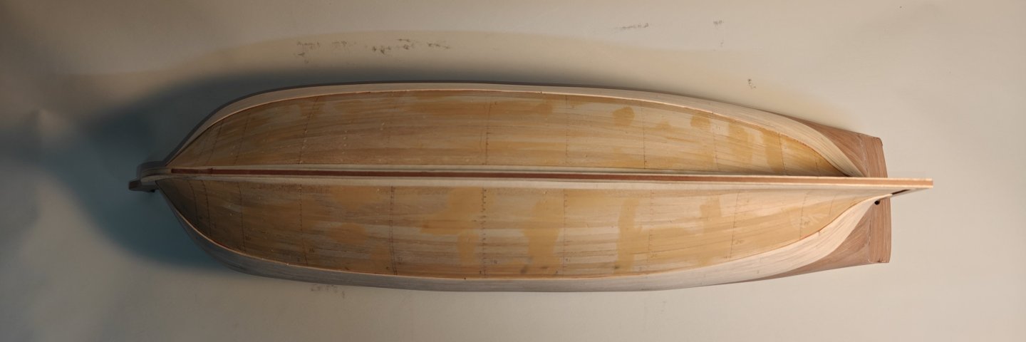
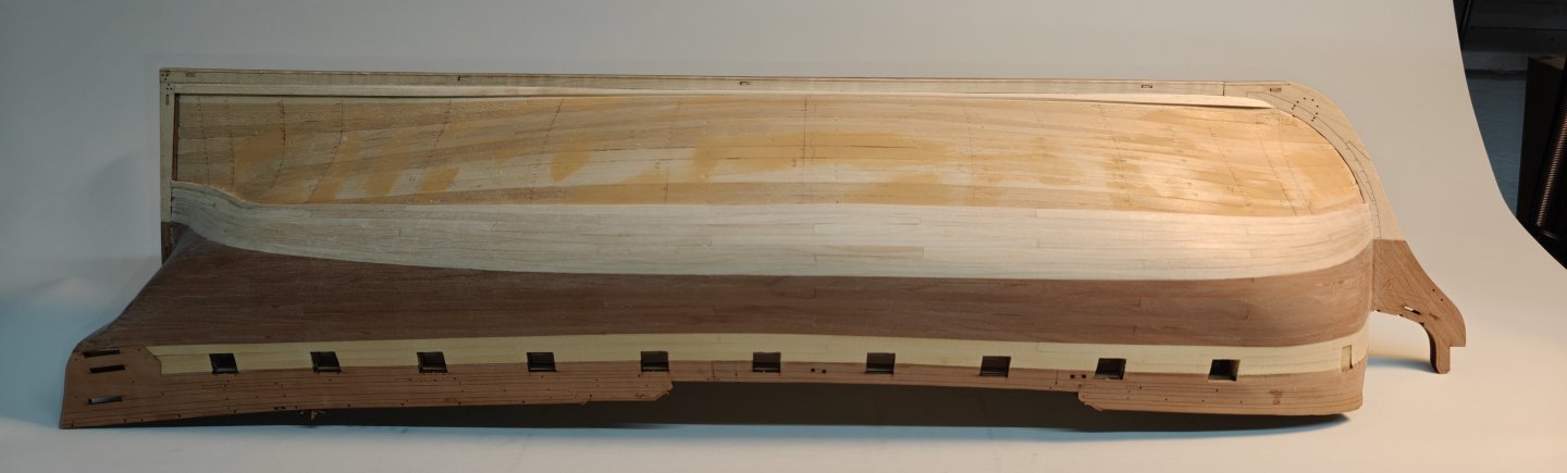
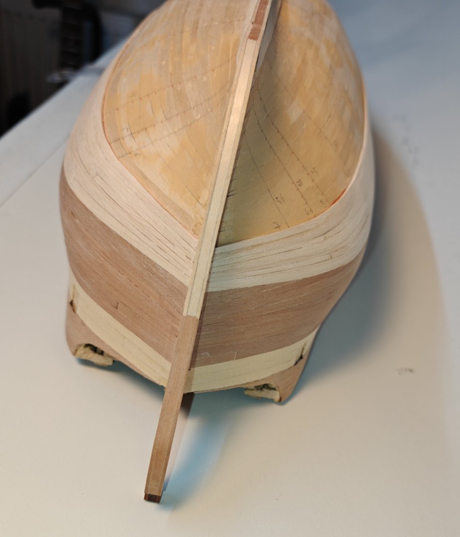
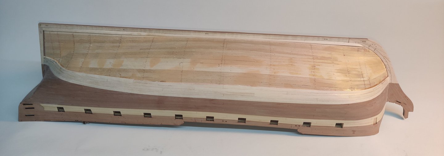
Log entry 23 - planking continued It has been a while since the last update. Things are moving forward, but it is painfully slow. This is in part because of my HDMS Elben detour, but more due to diving into resin 3D printing which has taken up quite some time lately. But I am getting the hang of that and will probably also be doing some ornaments for the Christiania with the 3D printer. I am playing around with the stern decorations and will show something soonish. In the meantime, more planks have been added, also at the stern. It is very time consuming to cut all the planks to size with none being full with all the length. And I often mess them up and have to re-do a plank. I think that on average I do almost all of them twice. Even then, the fit is not perfect with the strong curves and taper of the planks. But viewing from a few feet away, it looks reasonable to me. Still a ways to go, but we will get there eventually. The carrot is being able to move on with the very interesting steps that follow the planking. I am looking forward to doing the stern and the wales! BR TJM

- 148 replies
-
- 10
-
-
- Christiania
- Vanguard Models
- (and 1 more)
-
I have a white window blind I can roll down and use as a background for photos. If you have a fixed spot you can use, that works great. The ship is looking great!
- 422 replies
-
- 1
-
-
- Vanguard Models
- Sphinx
- (and 1 more)
-
Thanks! That is a great input! I can make two engraving runs, one for the nails at much lower intensity. Or I can of course forego the nails entirely. I will run a few tests 😁
-
Thanks for looking ito this! I read that as well at some point 🙂. It is just that the text on the drawings usually distinguish between short canon and carronades. There were several foundries in Helsingør and Copenhagen at the tine, so even if they were trying to systematize, I am not sure it is possible to rule out other sizes being produced. I also think that Elben may be a bit too early for the 1833 system. But it is of course possible that the short canon on Elben was actual carronades. Their use and powder charge would have been very similar, it is only a matter of the shape of the barrel and carriage.
-
I admit that I had never expected anyone else to have heard about this little Schooner, much less considered building it! That is amazing 😃. Indeed, the loss of Schleswig-Holstein is probably the biggest trauma in recent history for Denmark. The effect cannot be overestimated. Every Dane hears about this period multiple times in school, but I think not too many appreciate the importance for the forming of the current nation. Denmark's power had been declining for 2 centuries at this point, first with the loss of the southern Swedish provinces and then with the almost complete loss of the Navy in the Napoleonic wars which also led to the loss of Norway. Denmark was already at this point a small country with just a few oversees possessions. The loss of all of southern Jutland in 1864 was a massive blow to the national pride. Denmark lost 40 % of its land (non-overseas) and 38.5% of its population, going from 2.6 mio to 1.6 mio people. It is also interesting that all of southern Jutland below Kongeåen was lost, as the northern part of Schleswig was a de jure part of the kingdom, unlike the southern part and Holstein, which were not part of the Kingdom proper, but owned by the king (it is a strange and complicated setup that went back many centuries). Denmark became in effect one of Europe's smallest nation states after this, and we were close to bankruptcy too. It informed the neutrality policies of Denmark during the Great War and the 'acceptance' policy during the occupation of WWII. In fact, Denmark did not engage in any active wars again until 1999. I had not considered that the ship Elben would have been transferred to the SH navy after 1864, but that makes total sense. Regarding armament, I only know that it was designed for 8 short 12 pounders - whether it was ever armed with that is not certain. I have not been able to find any drawings of these guns in the archive - many others, but not these. That is not to say that they are not there! I just haven't found them 😃. However, their length in calibres seem to be the same as for the short 18 pounders above, which were widely used on many different kind of ships, so I am quite confident that it is just a question of scaling them down to 12 pounders.
-
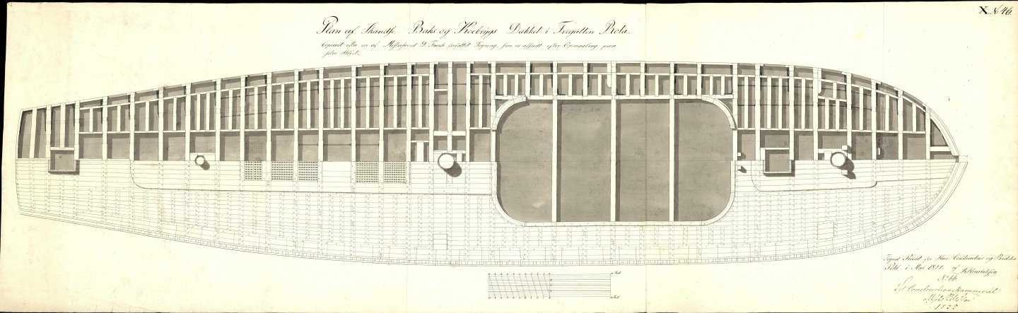
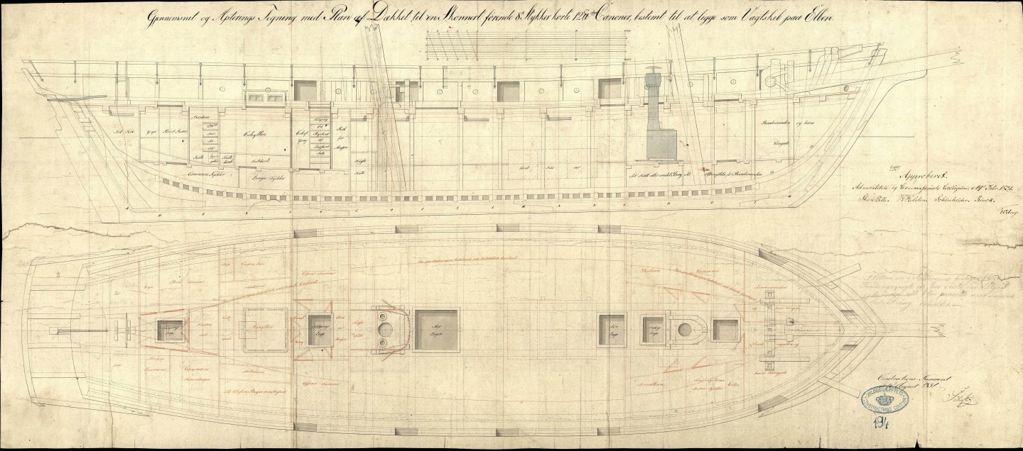
Thank you for the feedback - I have tried to do the planks as realistic as I can with the information I have. Apart from glancing at the Vanguard Models kits I have (Flirt and Sphinx) I have these contemporary drawings of deck planking, although for much larger ships than Elben: They are from the frigate Rota 1822 and the 3rd rate Dronning Marie 1824. I have used the drawing of Elben which shows the outer plank and one along the gratings: And i have placed the plank ends above where the beams are shown on the plans. The inaccuracy I know for sure I have in the current top deck is that I have not included the nails that are not at the plank ends. There should be two nails on all planks at all beam positions. I actually made the drawing like that, but found it became to busy/crowded. The Vanguard Models laser etched decks are correct in that way, but they have a more subdued brown tone. Mine get very dark, almost black and I was afraid it would distract too much. But I could just add those nails again and do another top deck. Perhaps I should try and then decide when I can make a direct comparison. If there are any other obvious inaccuracies that could be addressed, please ket me know. BR TJM


-
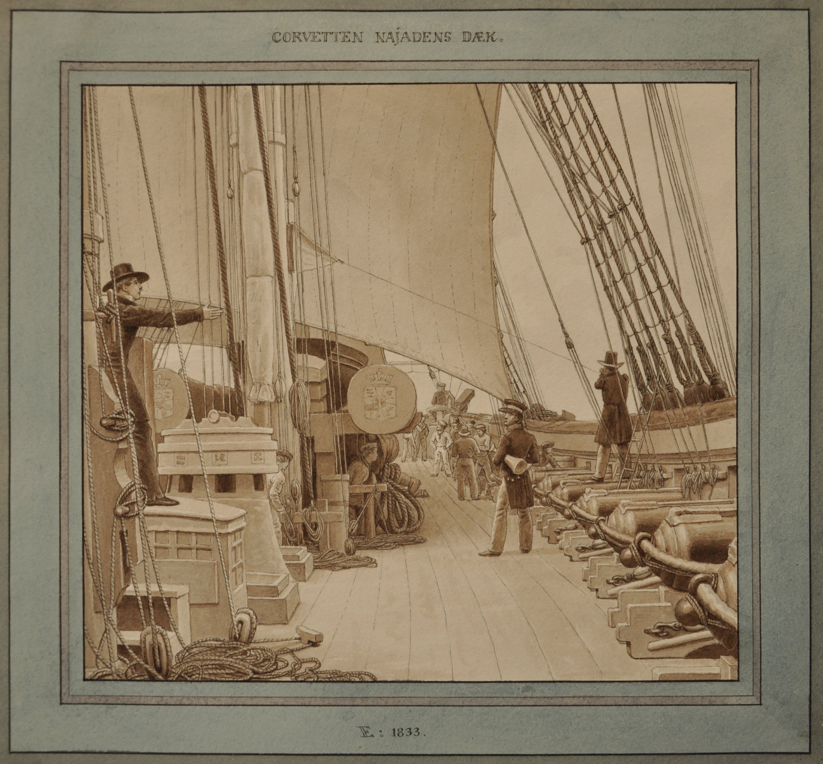
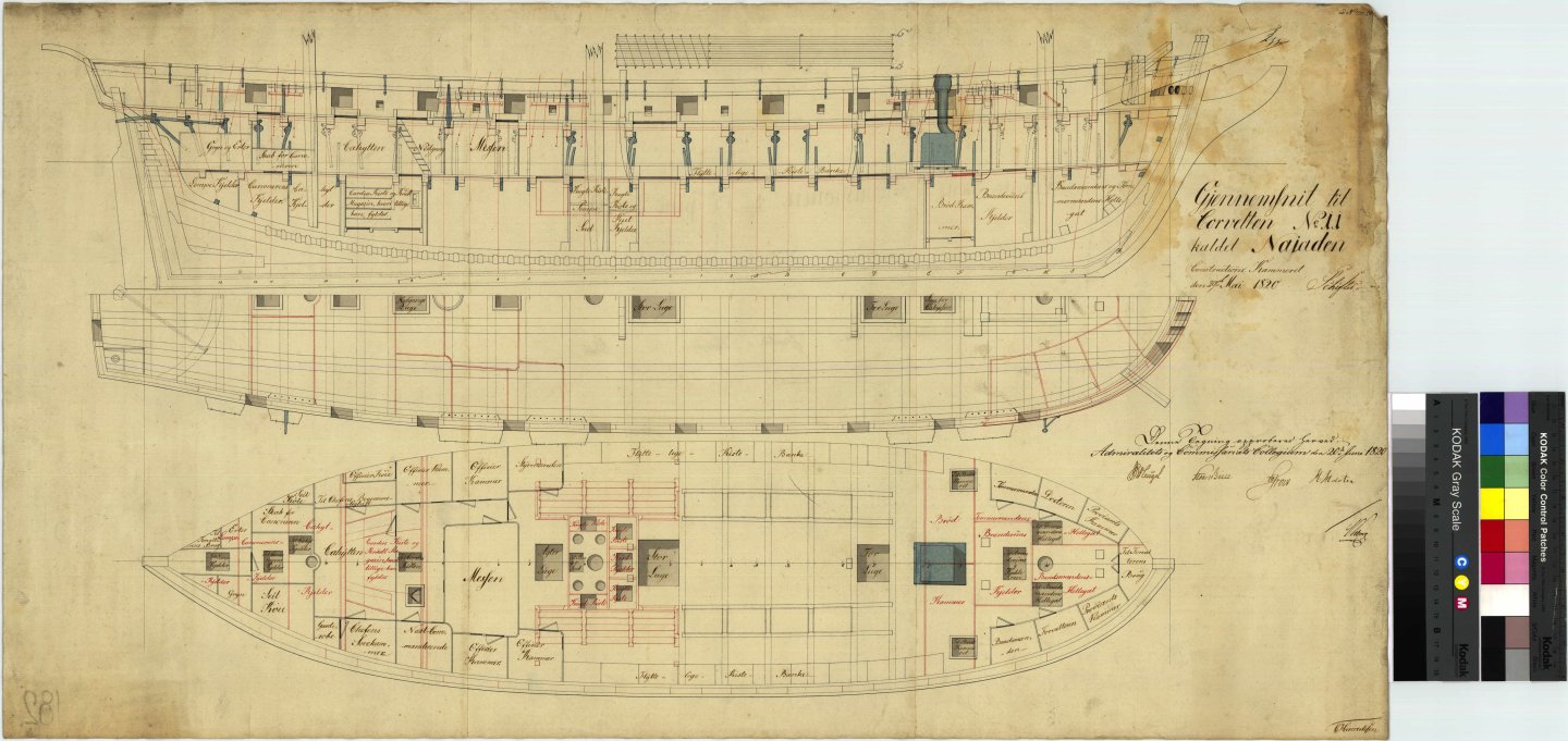
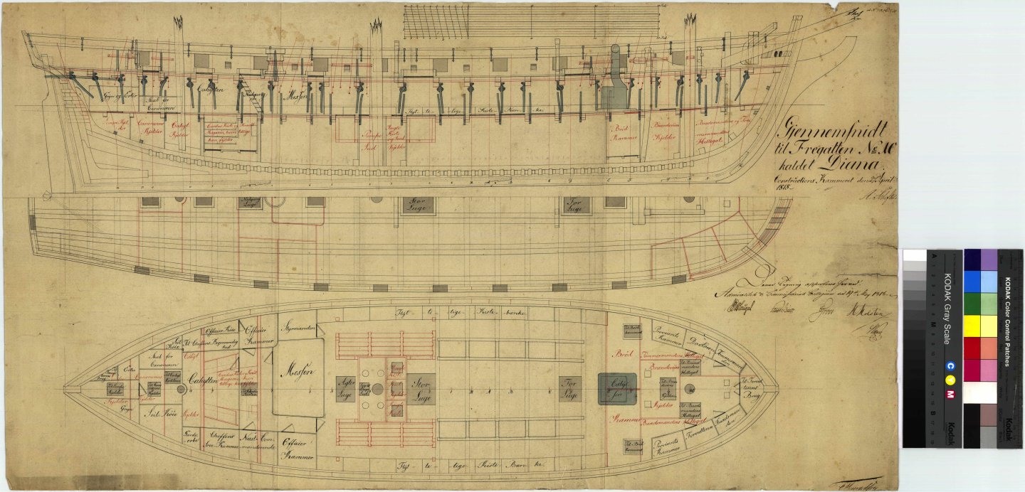
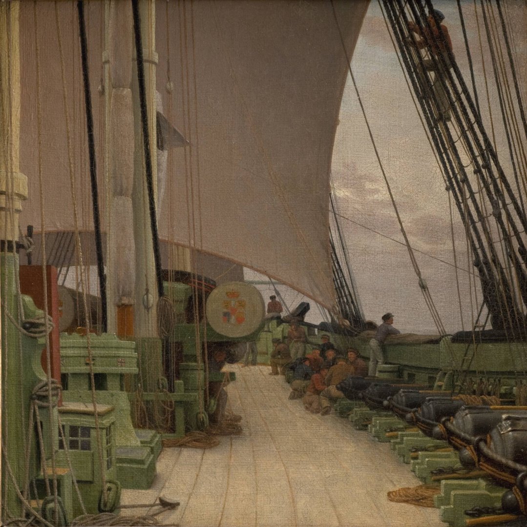
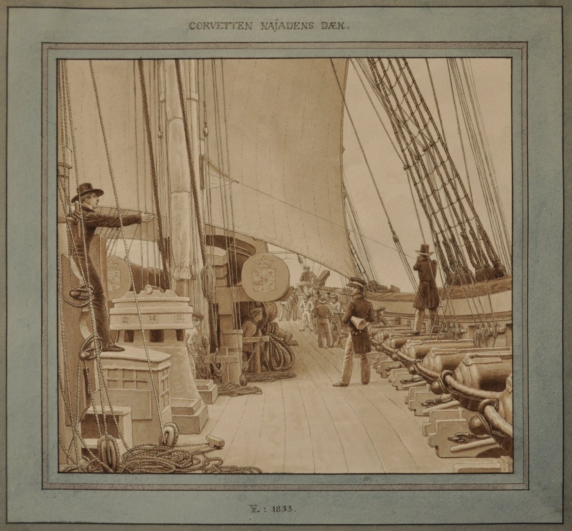
@Thukydides, I just went through the drawings I have of Najaden and it's sister Diana, and the vertical pin rack at the mizzen does not seem to appear on the drawings. There are two more copies like these, but they show the same. But then again, the skylight above the cabin (cahytten) depicted in Eckersbergs paintings are also not in these drawings. These features were likely added between the 1820 launch of the ship and 1833 when the pictures were painted.
-
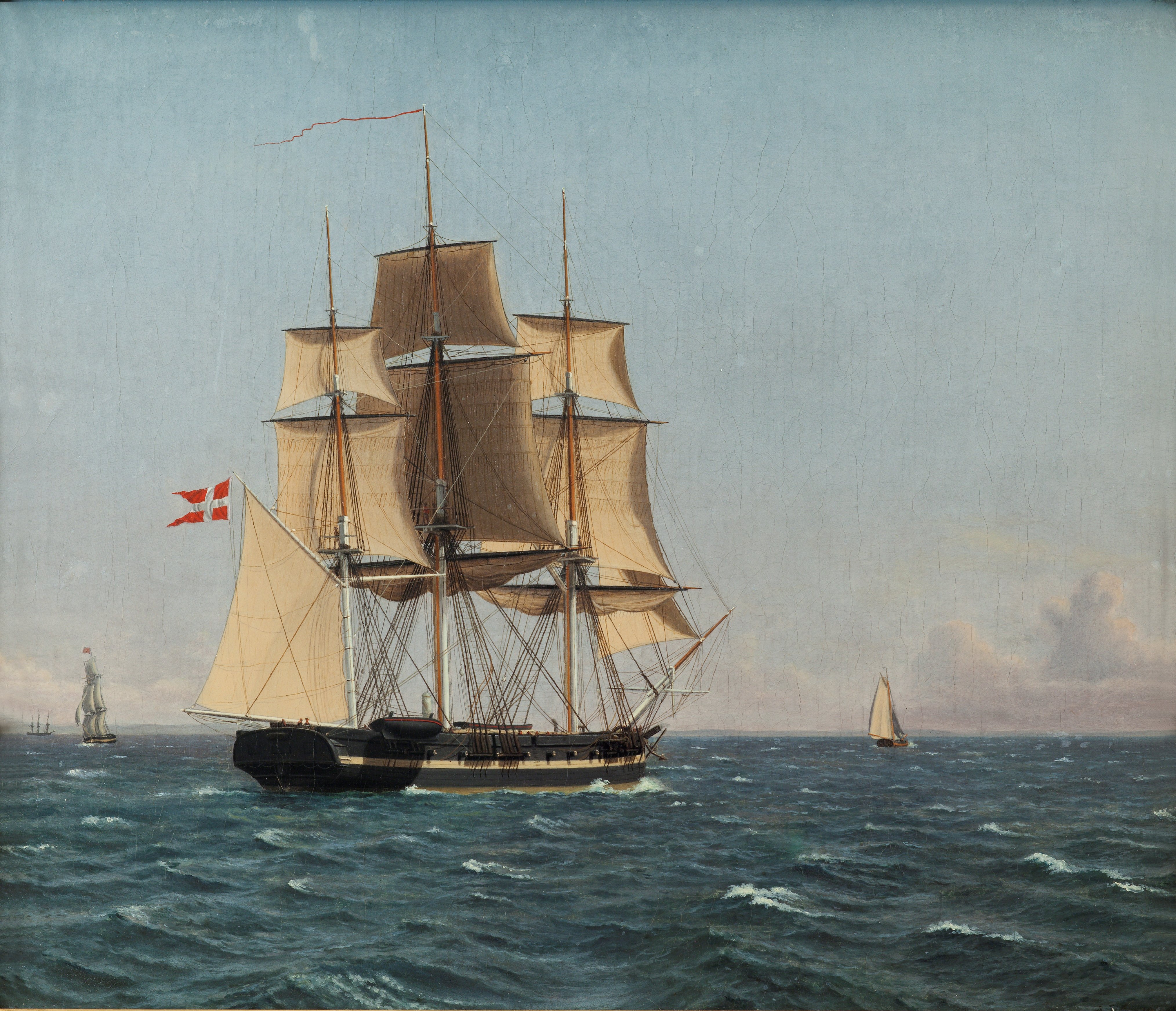
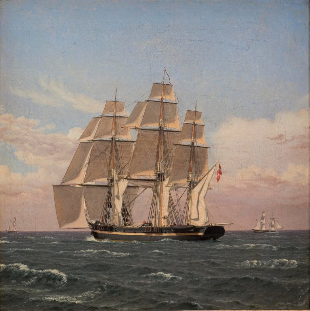
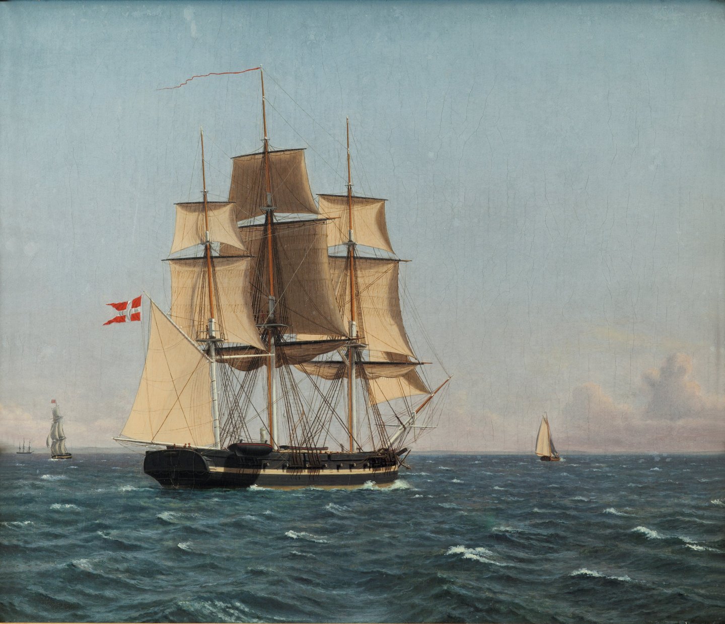
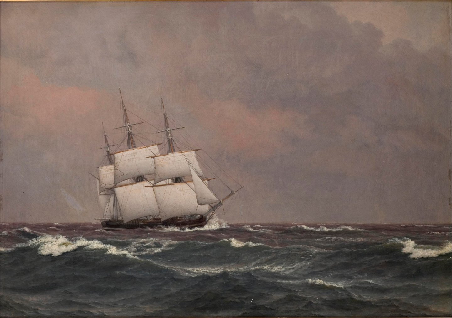
It is from 1833, https://open.smk.dk/artwork/image/KMS2060 . Eckersberg had full access to the wharfs at Holmen and often sailed with the navy to paint various scenes. His painting are likely very accurate, as he was very interested in the ins and outs of the sailing ships of the time and spend considerable time studying them here are a few more paintings from this trip aboard Najaden, of the ship itself: He would take a ship boat and sketch the ship from that.
-
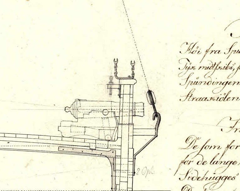
Oh, and I just remembered: I believe the canon had an 'eye' for the breach rope not shown on the drawings above! Here are a drawing and a painting by the famous marine painter C. W. Eckersberg, showing (likely) this pattern of short 18 pounder canon on the deck of the corvette Najaden: BR TJM
-
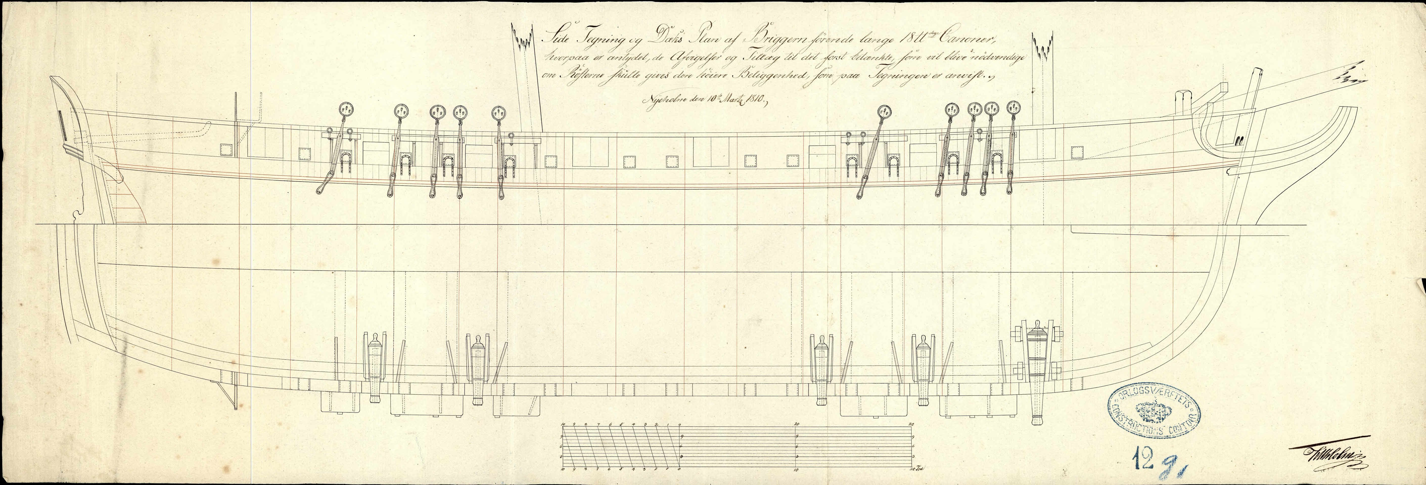
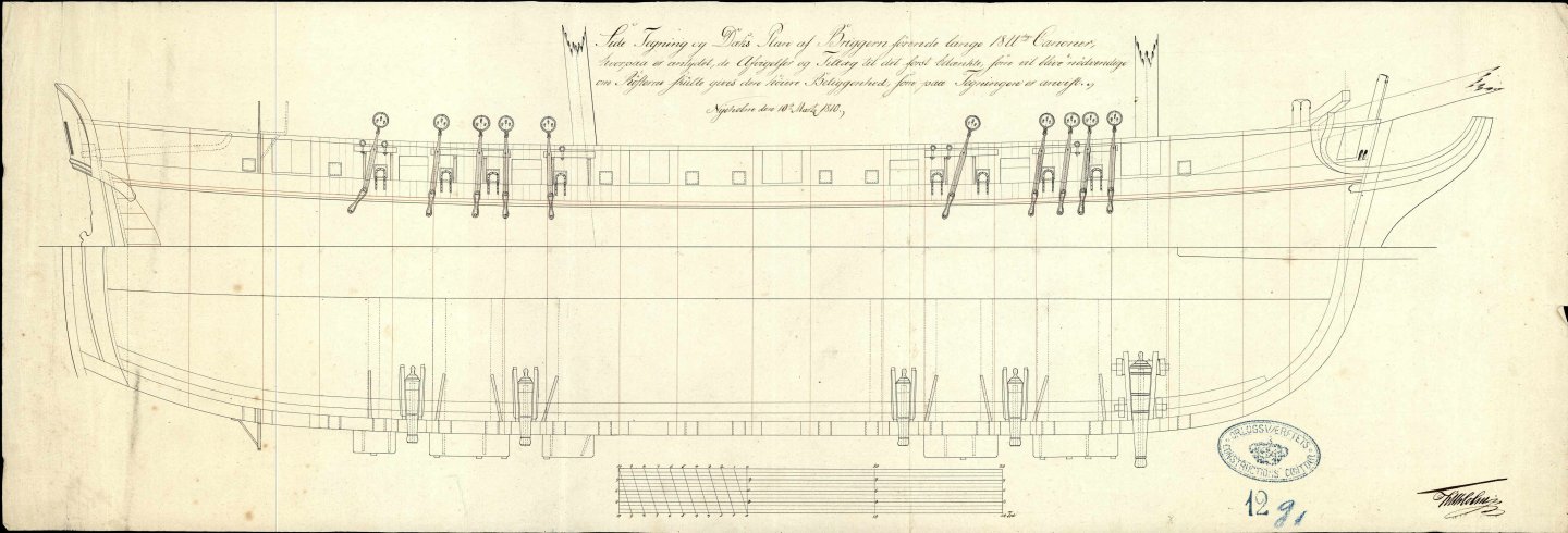
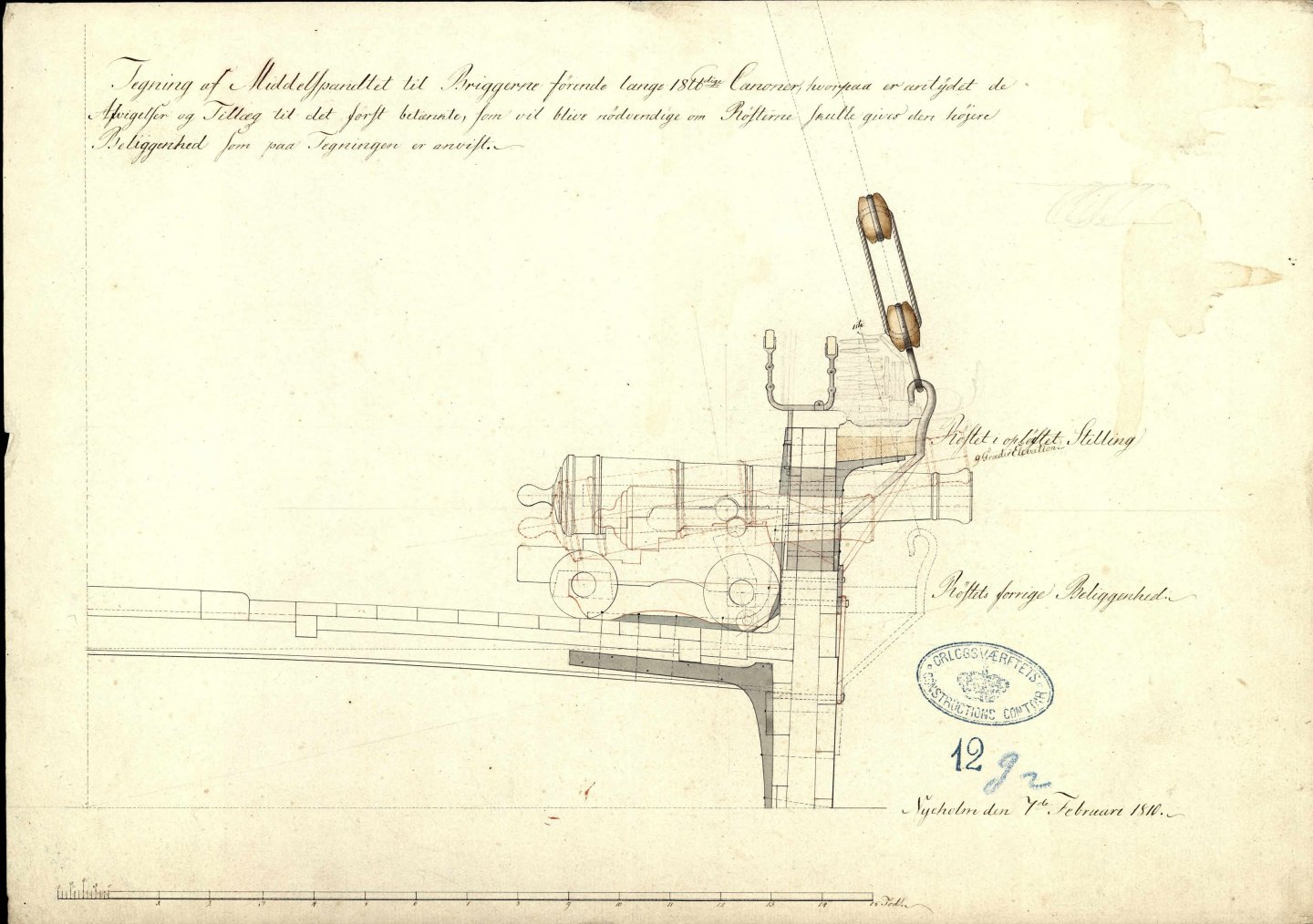
Wow, thank you Ron! That is very kind of you! I am afraid it does not get much better than that, but the full version has a scale that will be useful. This is an image of a short 18 pounder from the Lougen-class brigs, and I will simply scale that down to a 12 pounder for Elben. This is the full image: The original file is here: https://api.rigsarkivet.dk/ao/v1/images/31915669 There is also this one with a top view: https://api.rigsarkivet.dk/ao/v1/images/31915695 And this one with higher resolution but it has the standard and the short 18 pounders on top of each other: https://api.rigsarkivet.dk/ao/v1/images/31915697 Will these together do? Please note that a Danish foot ('fod') is 0.3139 m! Again, thank you so much for offering to make 3D drawing of this! BR Thorbjørn
-
Hehe, I mean, the laser is a bit expensive, but the small 3D printer really isn't! It is just a bit of a learning curve to get it working and cleanup, safe disposal of everything that has been in contact with the resin is a bit of a hassle...
-
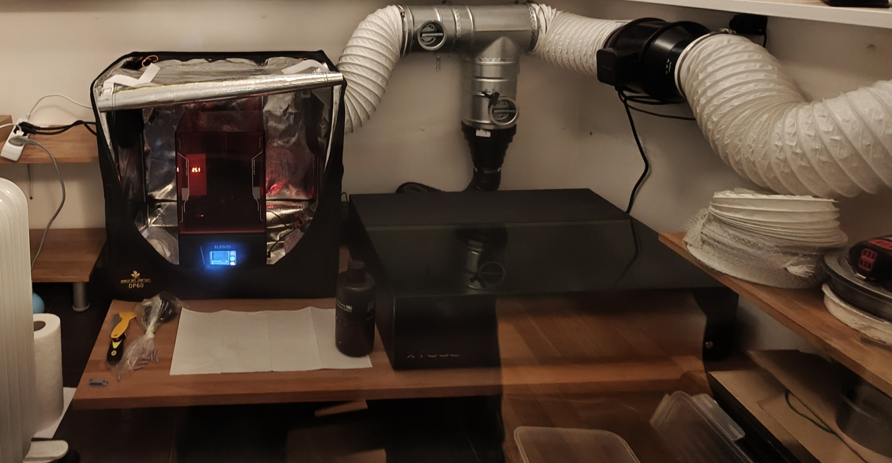
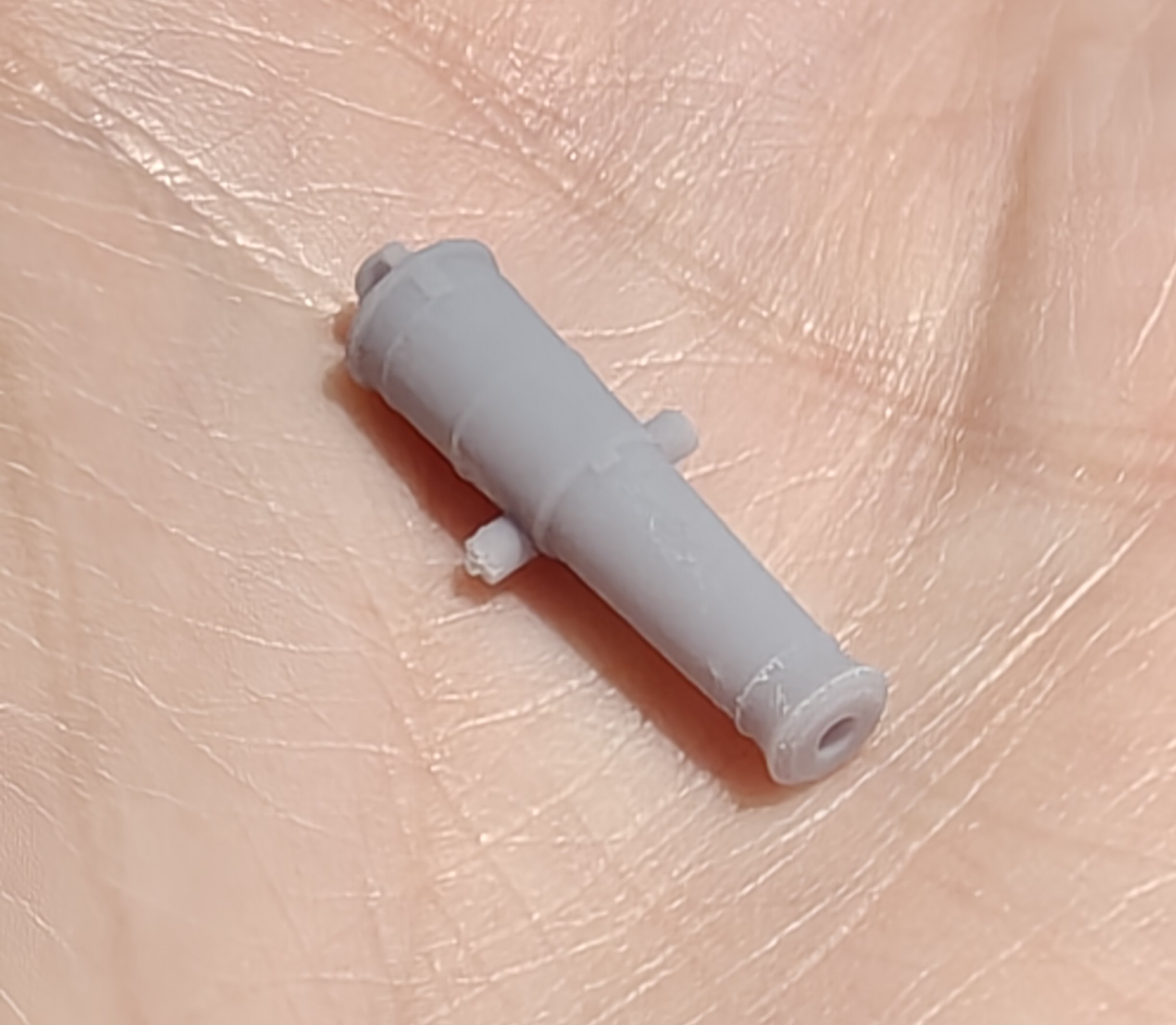
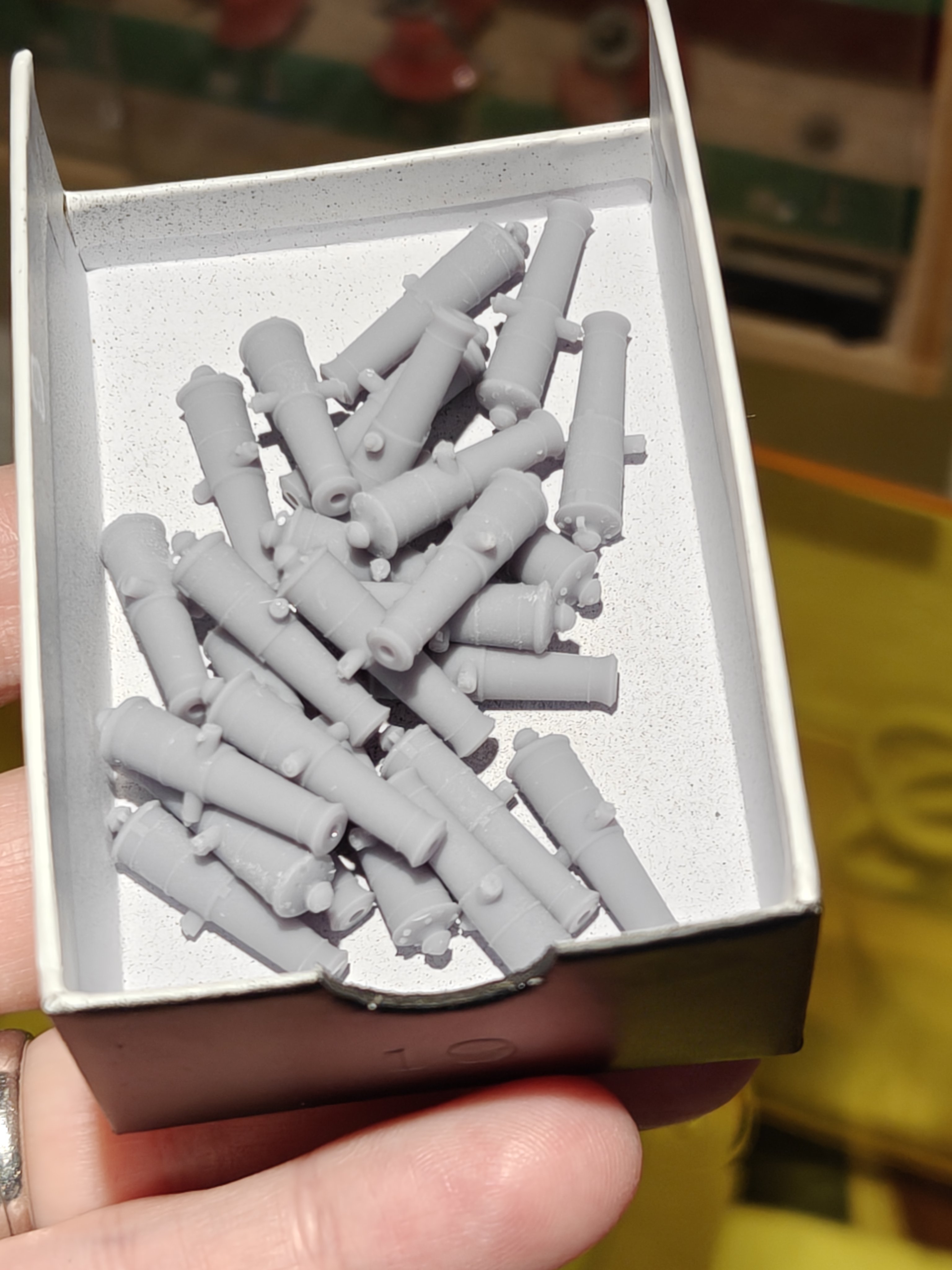
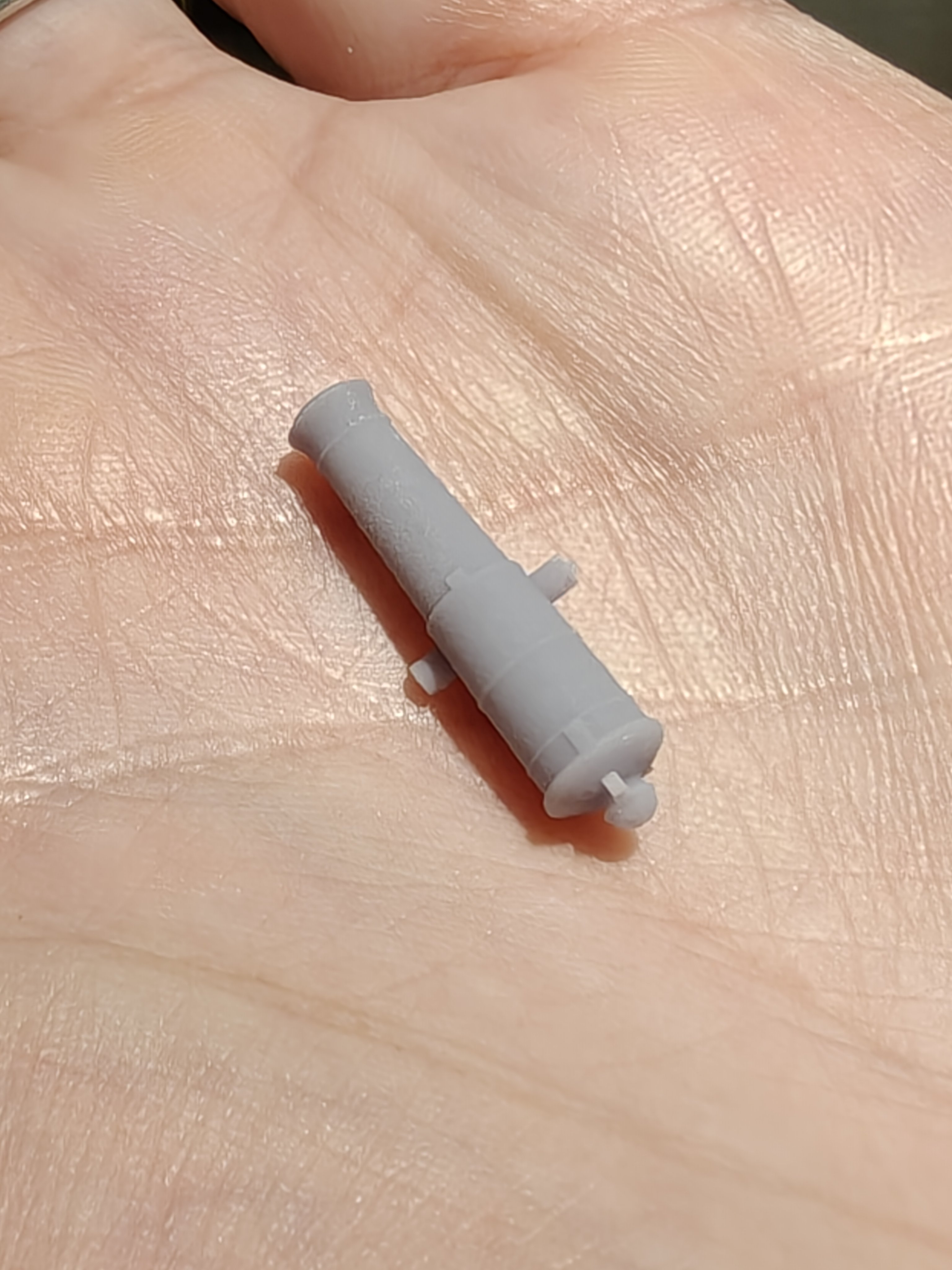
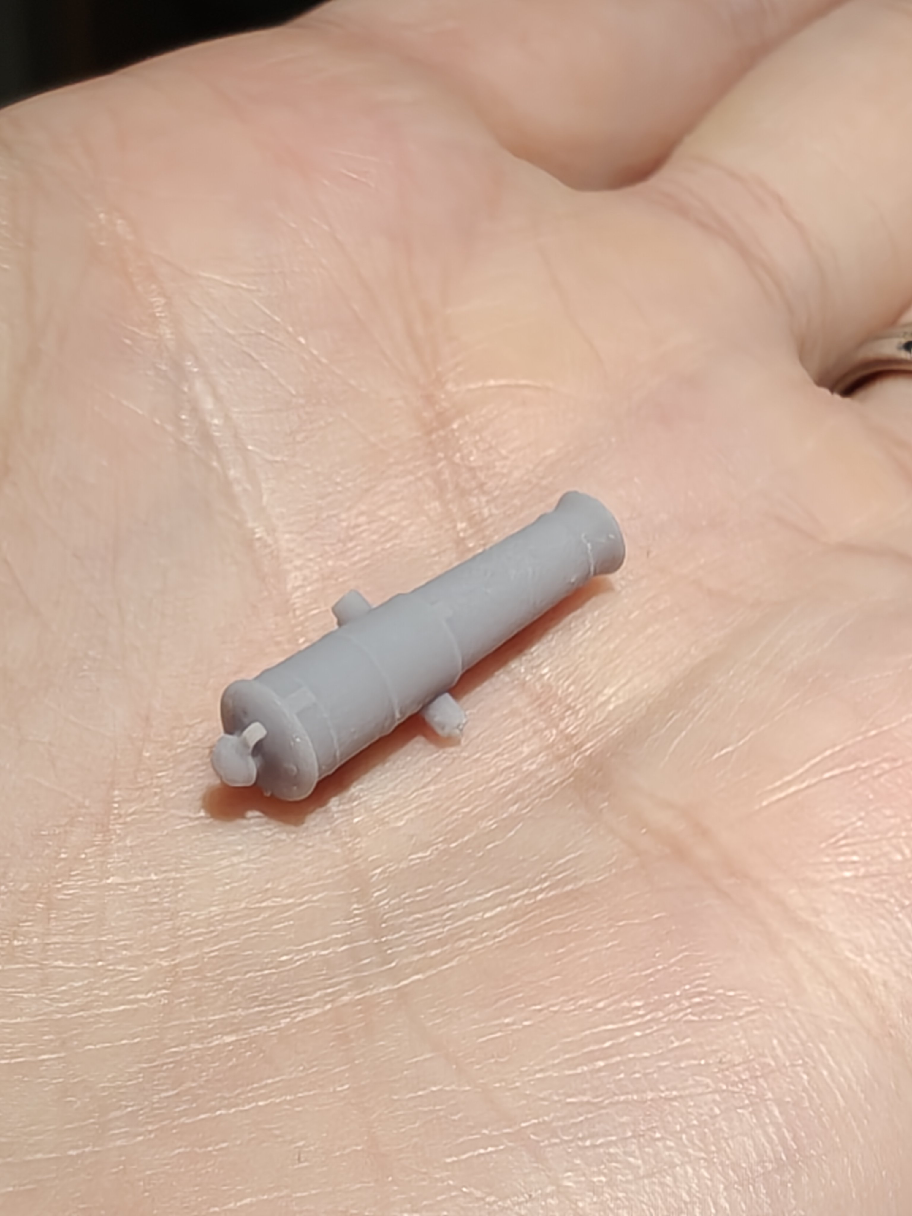
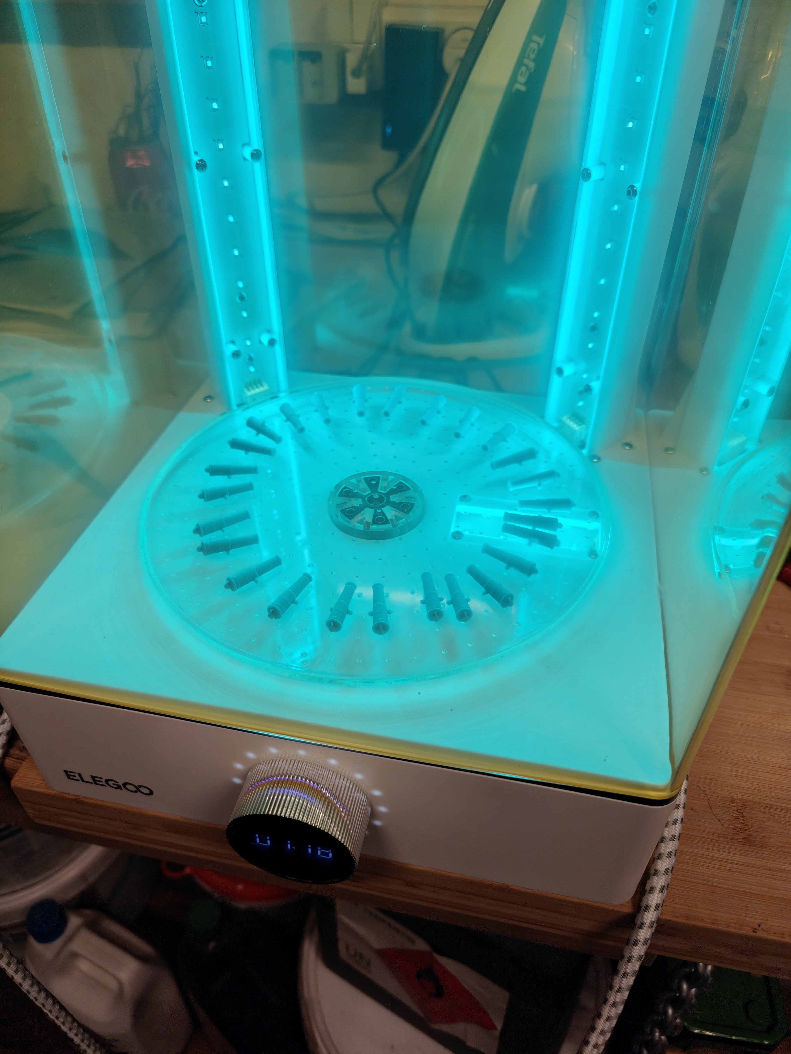
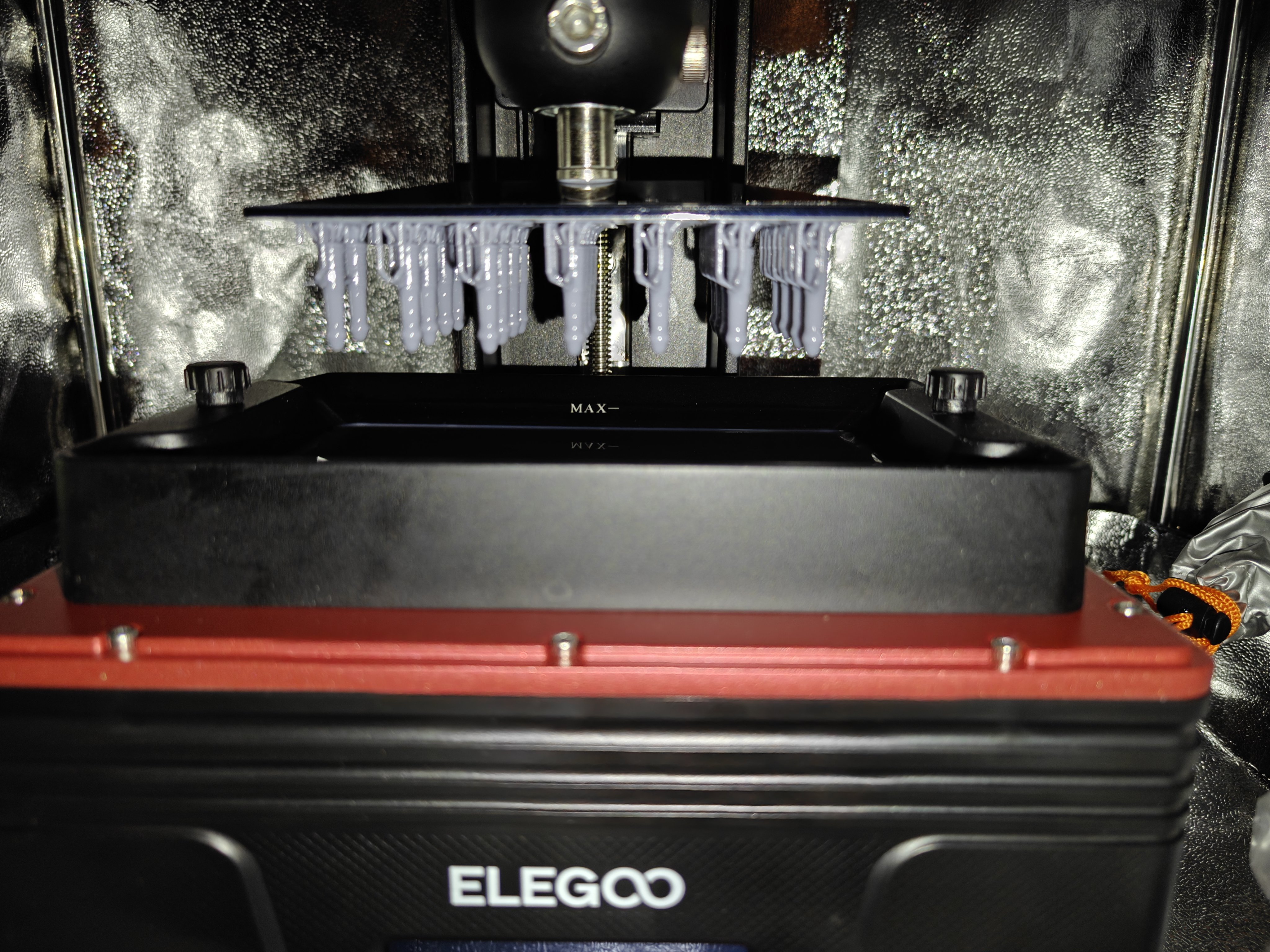
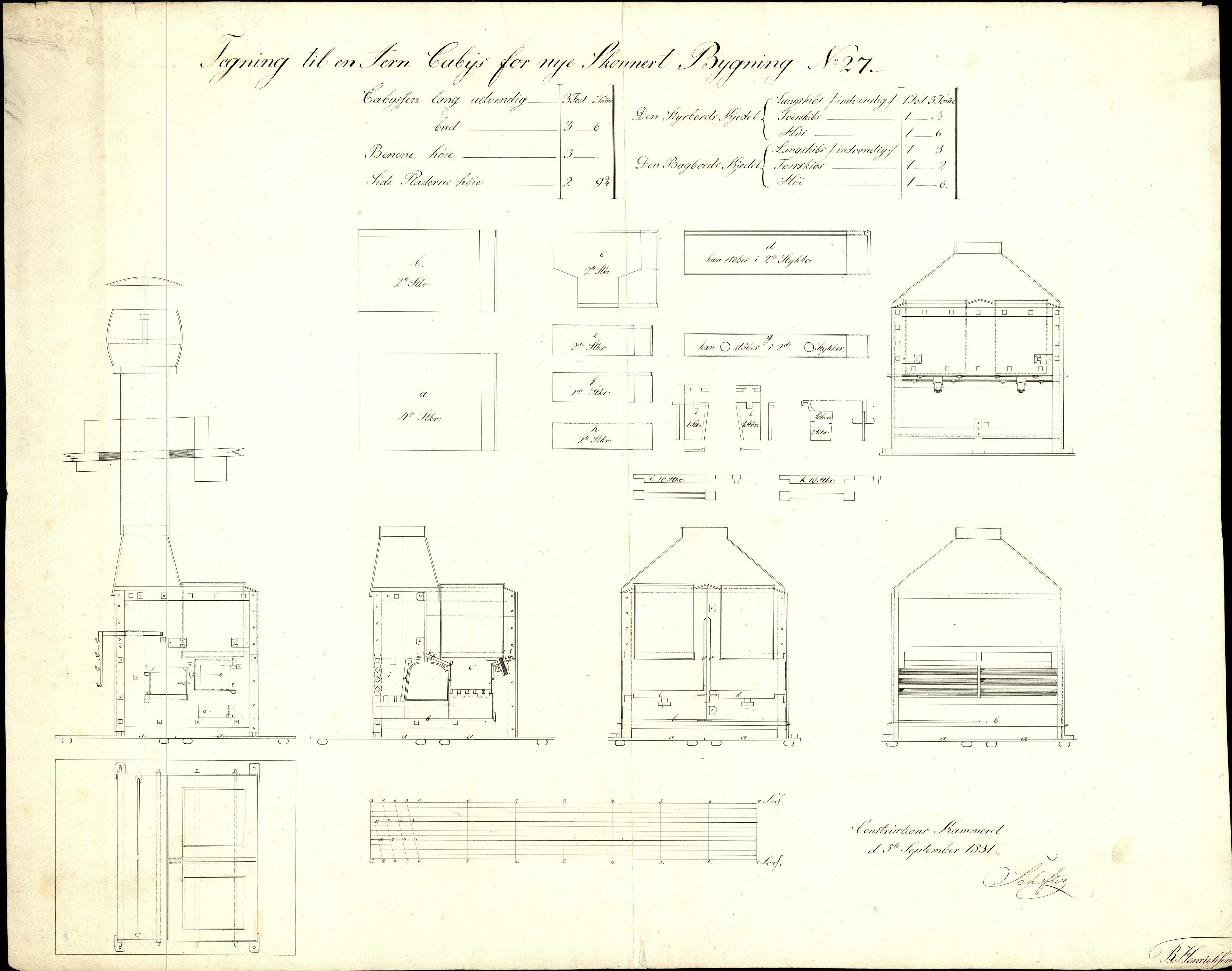
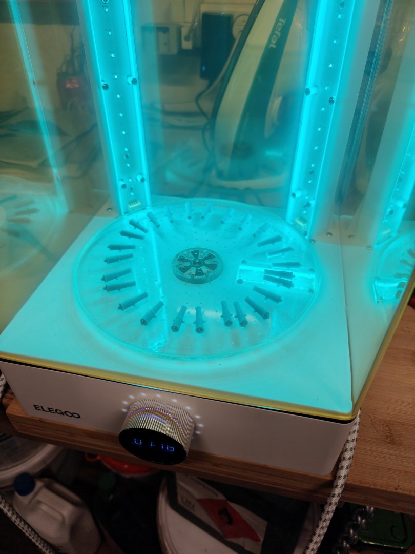
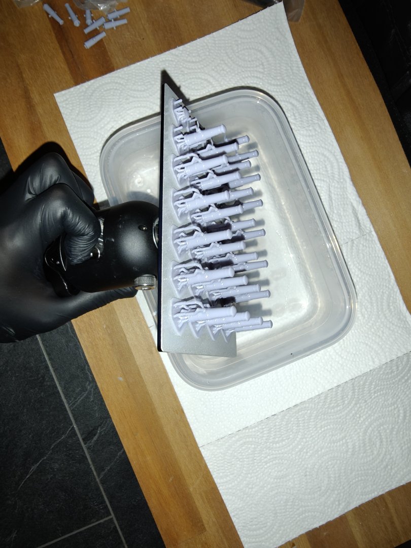
Log entry 3 - learning 3D printing! I got a small resin 3D printer for Christmas and have been spending the past month getting all the accessories needed and for moving both it and the laser into a new place. Most the setup concerns making sure there is adequate ventilation in place. This the setup now and it seems to be working well! The small very short 12 pounder canon needed for Elben was the first real test apart from a calibration print, mainly because it does not take too long to print. I am a total novice when it comes to 3D modeling, so I had to find a base to start from. Luckily @thibaultron has made a masterclass in printing canon here: https://modelshipworld.com/topic/34442-3d-printing-cannons-in-resin and he has also published a very comprehensive set of stl files of different patters and sizes of canon. I have modified his Bloomfield design to match the dimentions of the short 12 pdrs I need. In the first batch I printed, 2/3 came off their supports and I had to do a full vat clean - and messed up the pour, so I had a lot of cleaning to do! The rest 1/3 came out mostly ok, but with a bit of the knob at the end missing. I diagnosed the problem to be due to too little support area from the light supports I had used and therefore went with medium supports and more of them for my second try. I was happy to see 30 out of 32 canon sitting on the build plate after 2.5 hours! The last two probably got ripped off their supports due to a slight tilt on the build plate. But lots of supports are definitely needed! I am using water water washable resin, so the initial wash is in water (all gathered in bottles for later safe disposal) and the a quick ethanol/isopropyl alcohol wash. Then a final 3 min alkohol wash in an ultrasound bath and drying. Here are 30 canon being cured for a total of 5 min (probably too much, but I am being cautious here) And the final result: Here is the reference drawing of the short 18 pounder I used as a basis: Now I just need to design the carriage... I am very happy with how these came out! And a great success for my first efforts in the 3D printing department. I am looking forward to trying out different things. BR TJM


- 56 replies
-
- 10
-
-

-
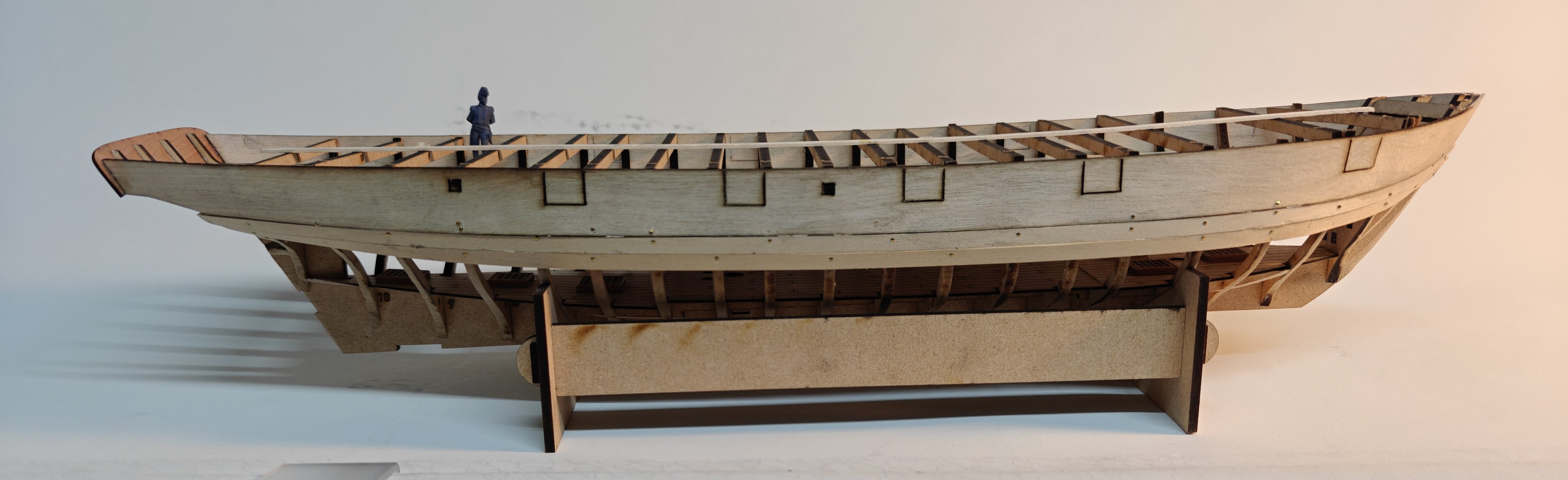
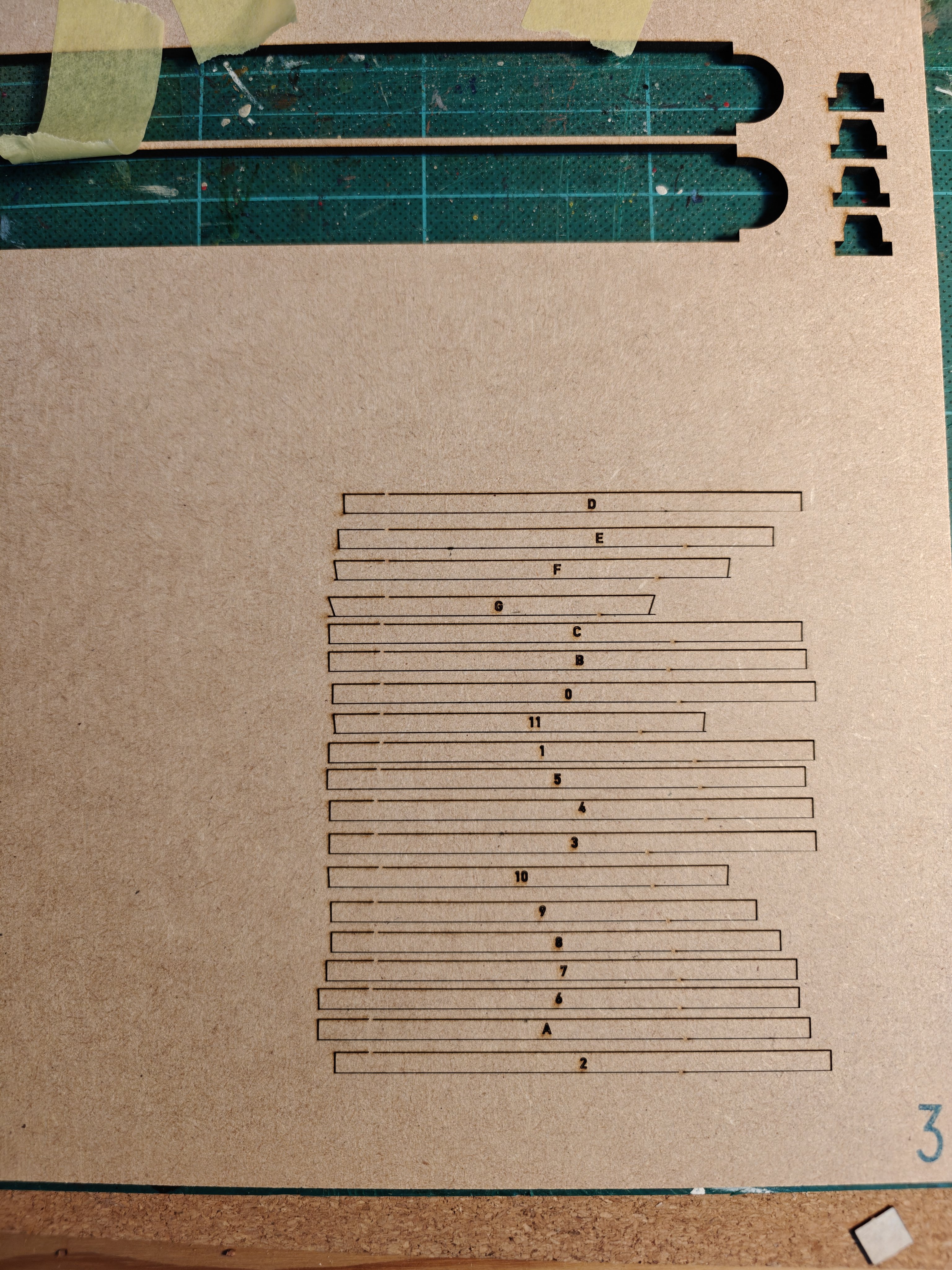
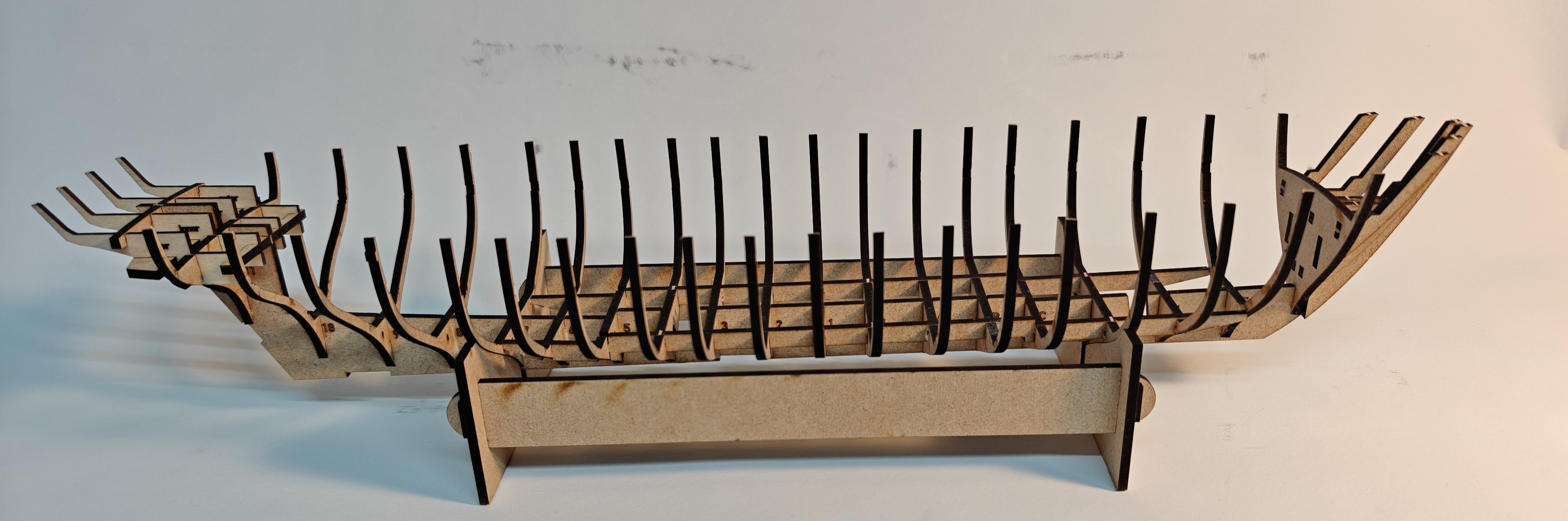
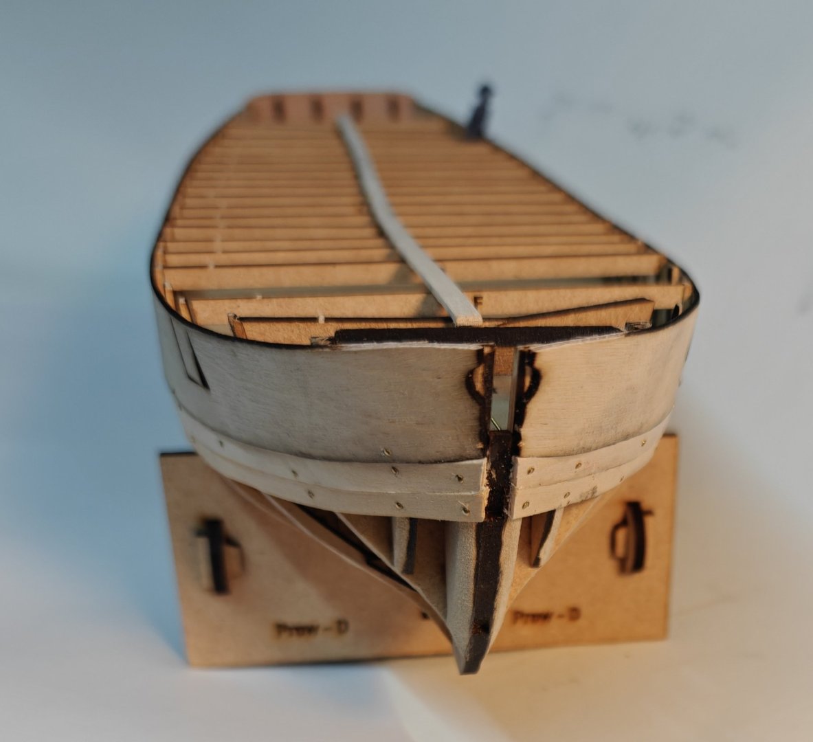
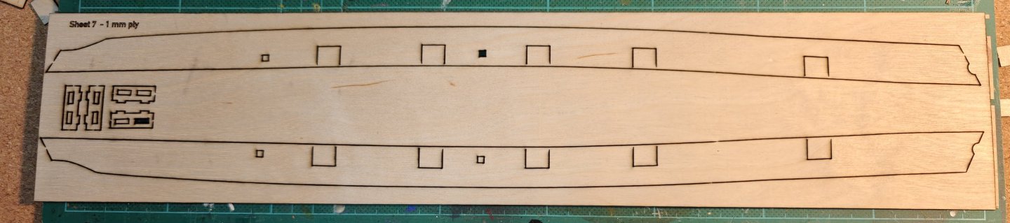
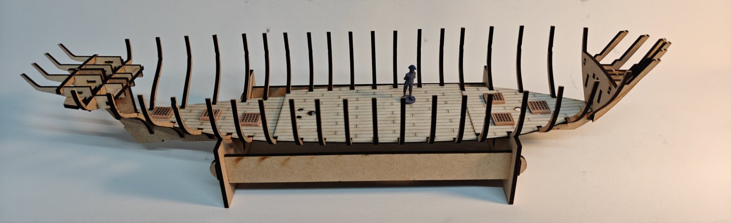
Log entry 2 - bulwark patterns Things are progressing quite fast at this point, at least faster than I thought! I cut out the bulkhead braces mentioned in the previous posts: These were then glued to their respective bulkheads: I also added a strip of wood down the middle to give some more lateral strength. After this, fairing was done quickly; the hull only really tapers at the prow and stern and very little material actually needed to be removed. Using the initial cardboard bulwark templates, I made some modifications at the prow to the patterns, cut another cardboard template and made the last small modification to the cut file. Here are the final 1 mm ply sheet: It includes the 4 small cabin frames as well. Instead of soaking in hot water and forming directly against the (braced) bulkheads, I just wetted the patterns an used a hot iron at the highest setting to shape the patterns off model. The fit came quite close and I could glue the patterns to at the bottom and then make final adjustments to their shape with the iron on the model. In this way, I don't have a lot of clamping force needed to shape the patterns, which is good, as the frame is a bit too fragile. You may notice two small notches in the patterns. These fit with registering 'pins' cut into two of the bulkheads. As no fairing is needed on these flat parts of the hull, it is a good way to ensure that the patters sit at the same height on both sides. I also added the first two inner planking strips and to my relief, the hull frame is just strong enough to take the abuse of pinning, handling, etc. But I will use sturdier frame for future projects! Lastly, I added the stern pattern. It looks askew in the stern photo, but it really isn't. I like to get this on to protect the stern frames from damage during planking. Planking the first layer should be relatively straight forward from this point! BR TJM


- 56 replies
-
- 10
-
-
Thank you all for your interest, likes and comments! @Dr PR, that is more or less what I have been doing. Since I will be cutting off the top part of the bulkheads anyway, I dont need them in 'good shape', I just need their outer curvature to be precise while i form the plywood. I have therefore just made some braces with the correct length and inner curvature that I glue in and everything becomes stable. With regards to material choice, MDF does cut a little easier, but that is not the main reason for choosing it. There are no warping on the MDF sheets and it sands very much easier than ply when fairing the hull - those are my main reasons for going with MDF.
-
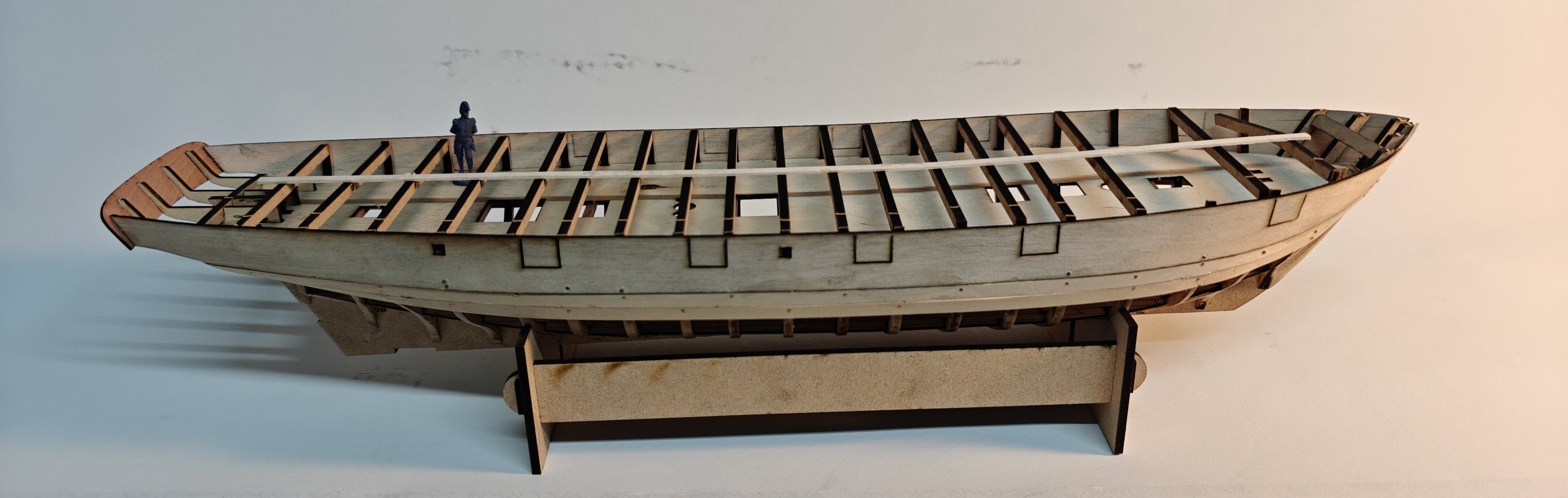
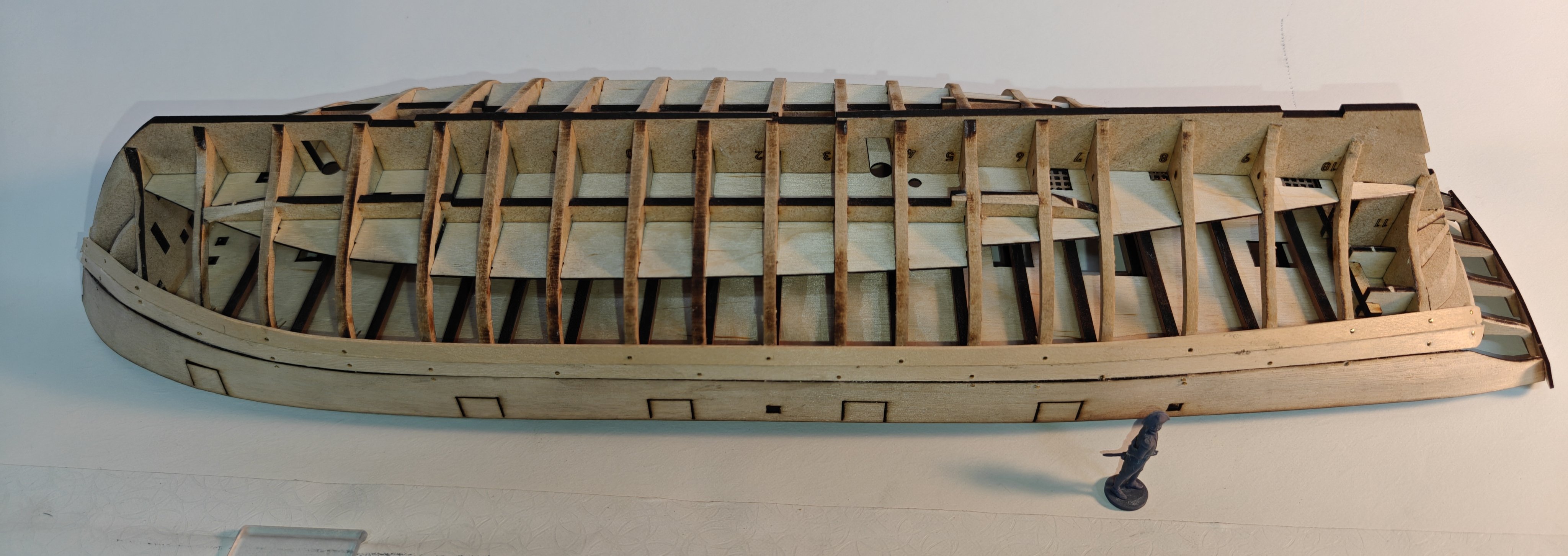
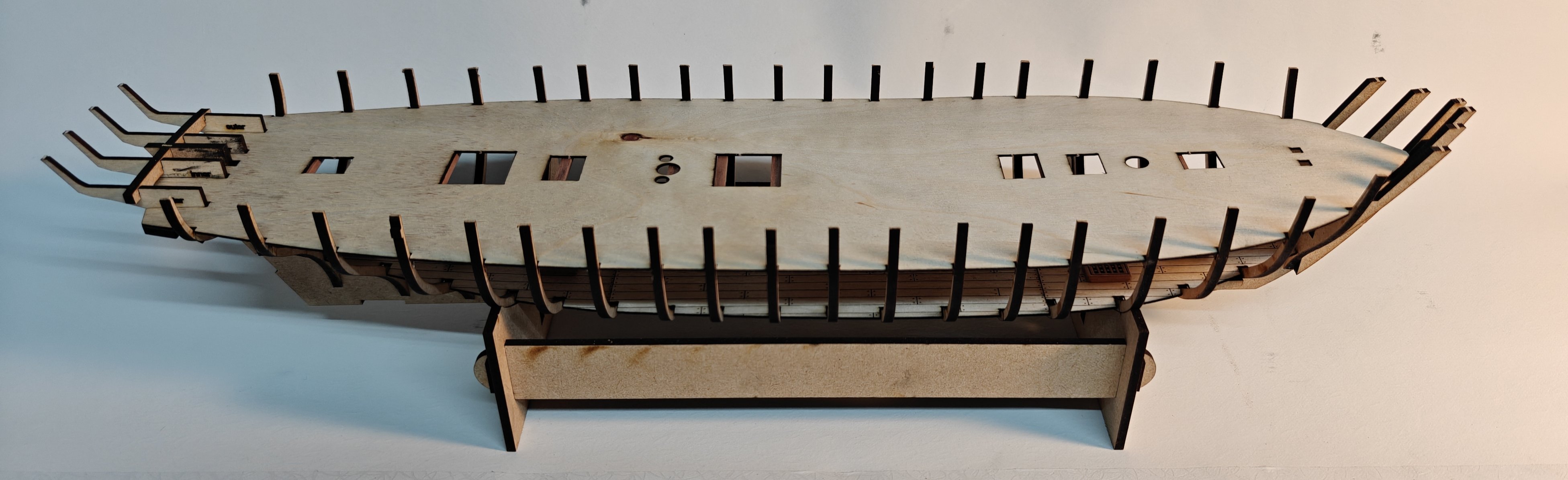
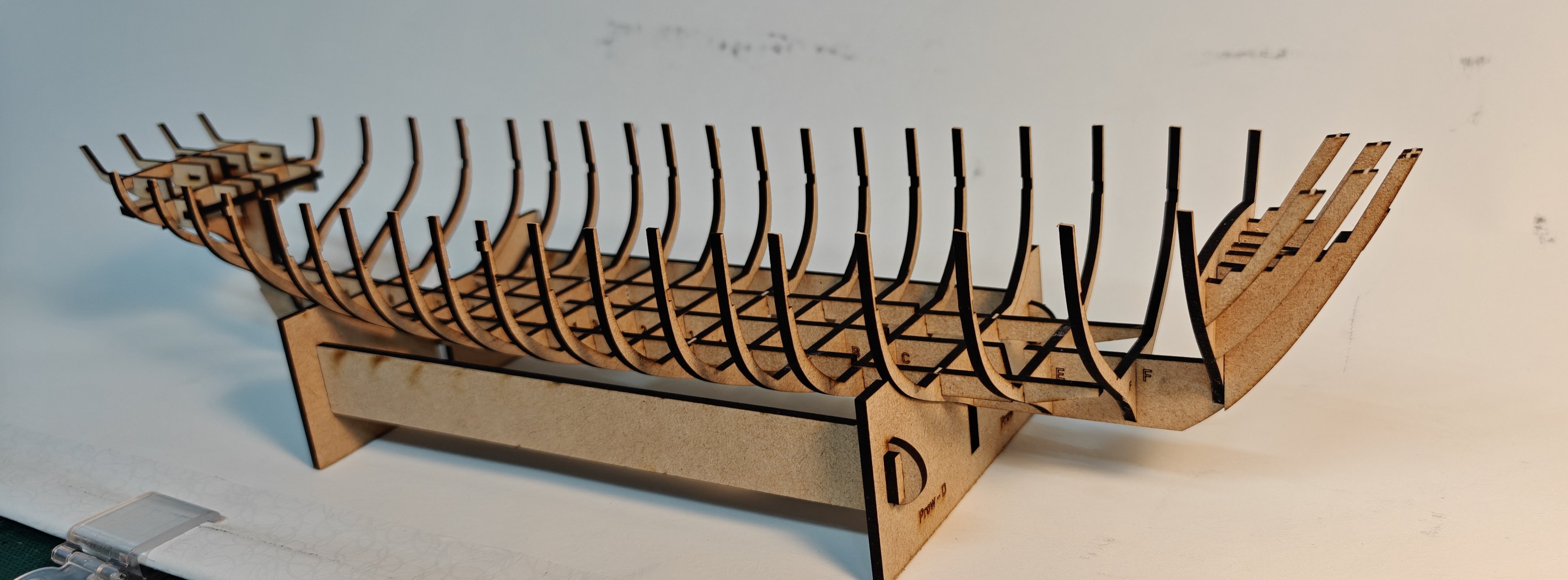
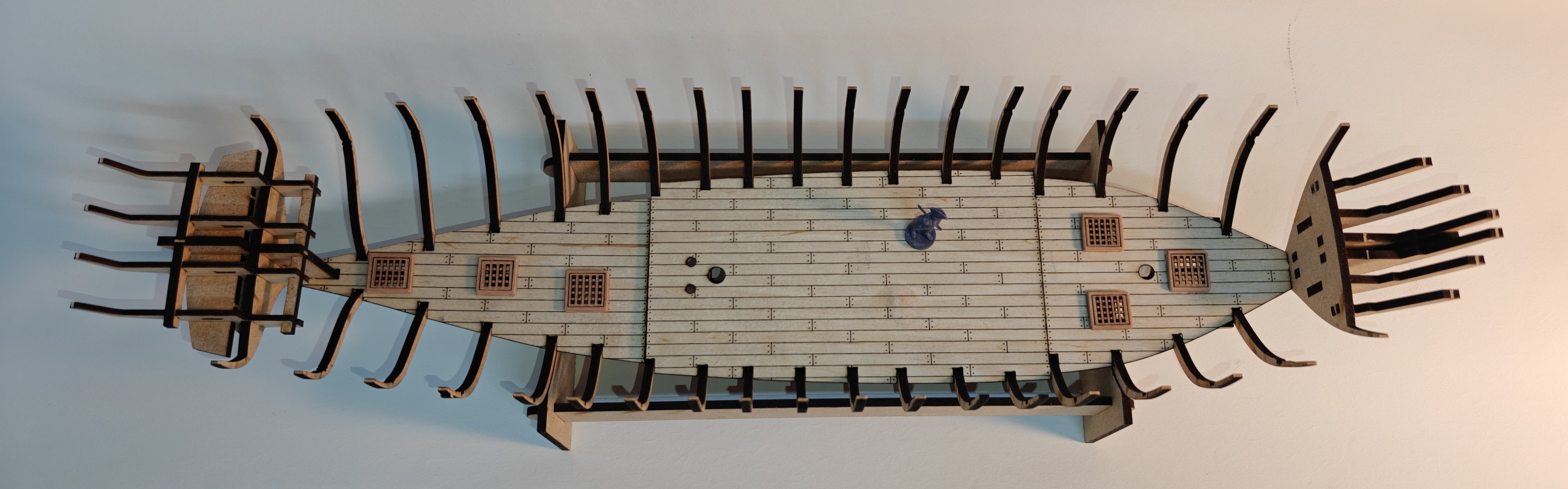
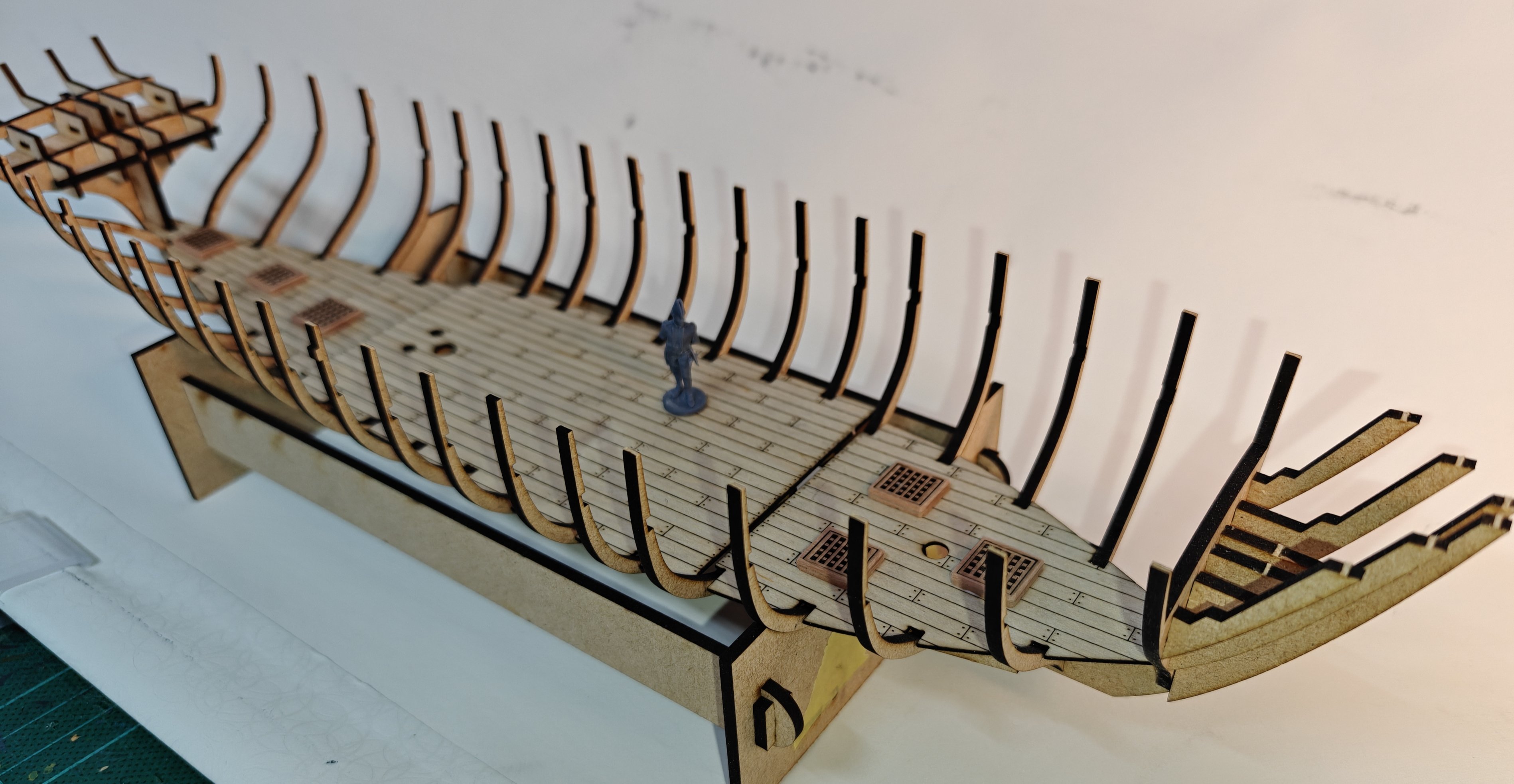
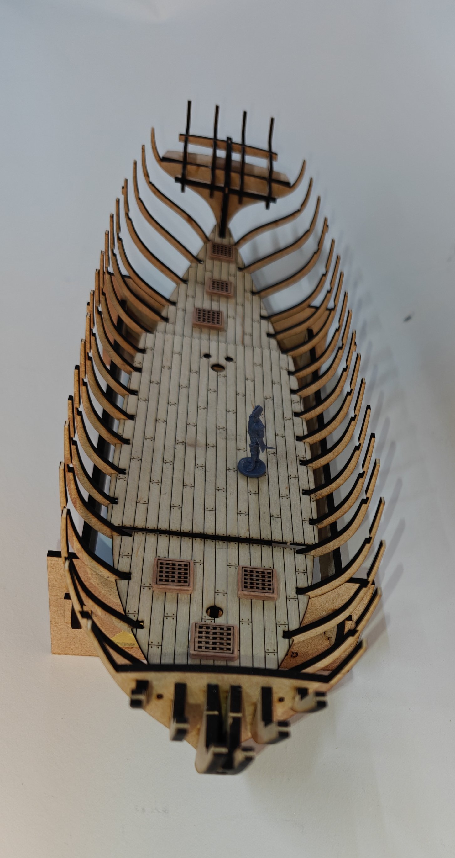
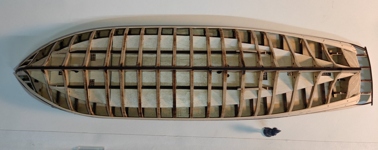
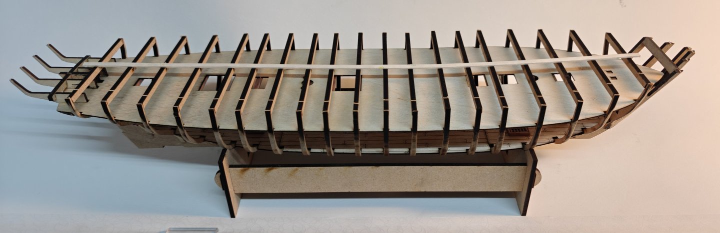
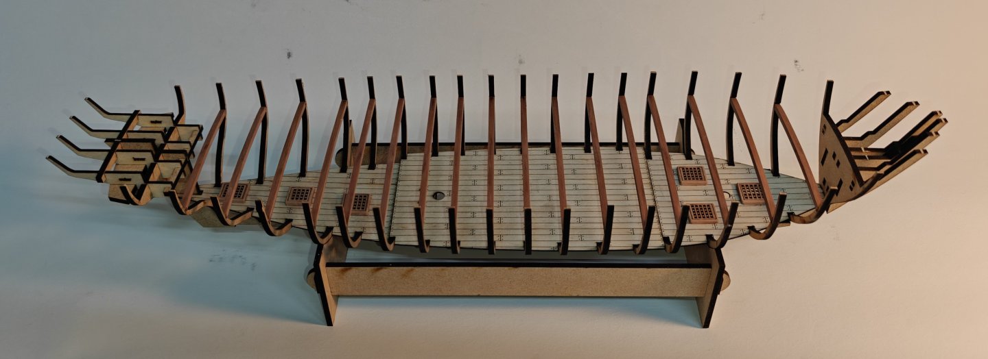
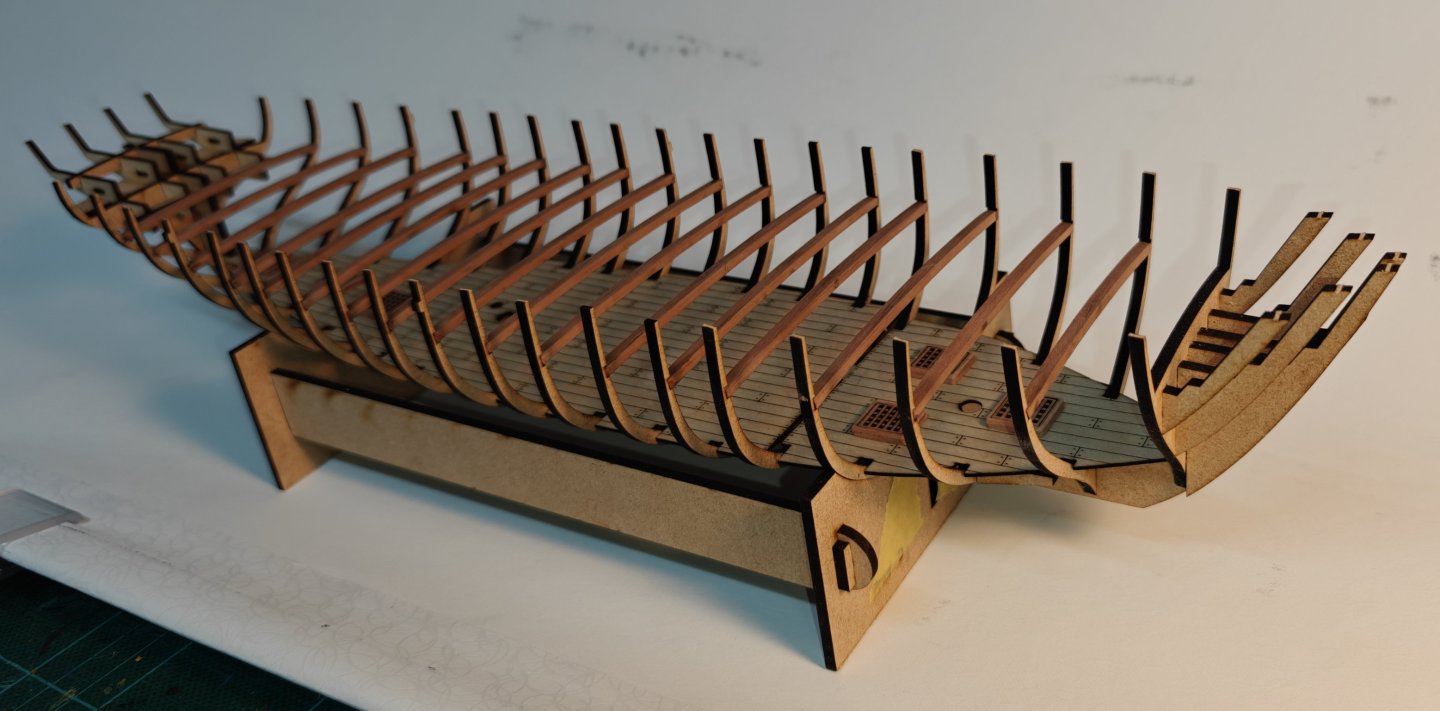
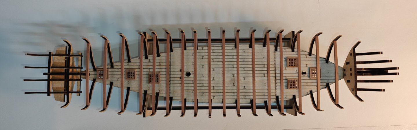
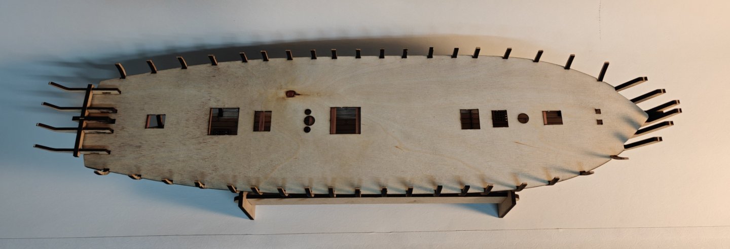
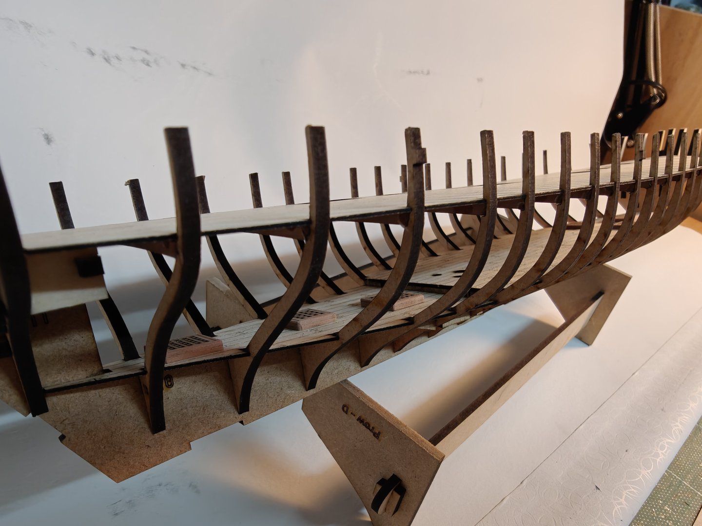
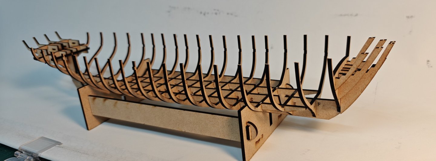
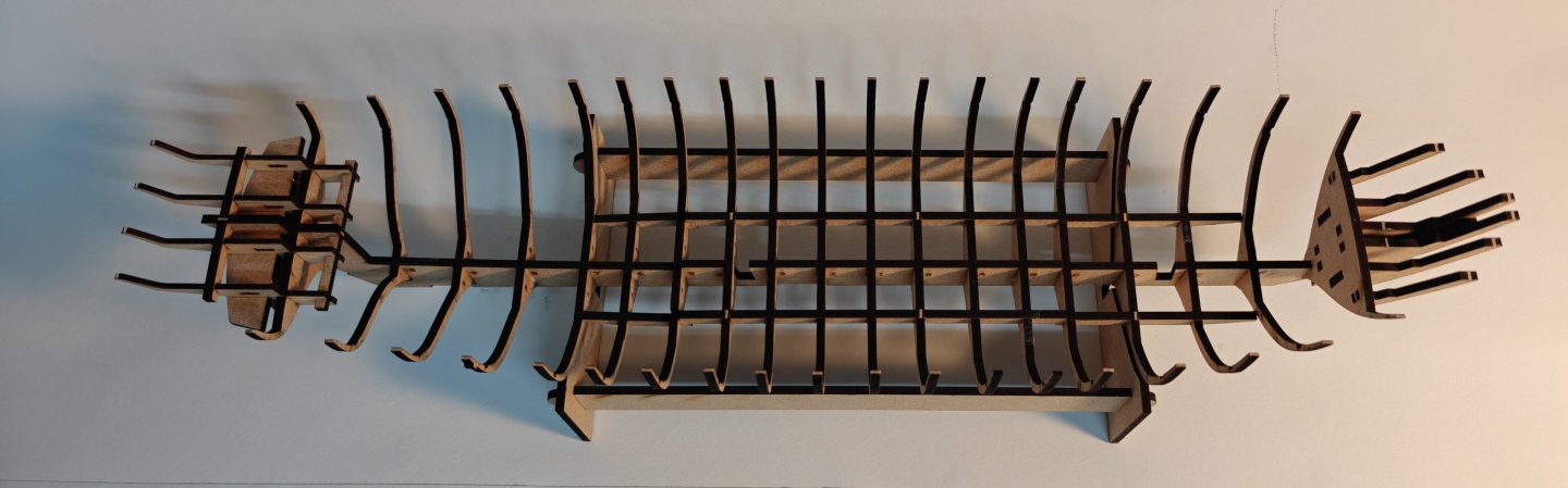
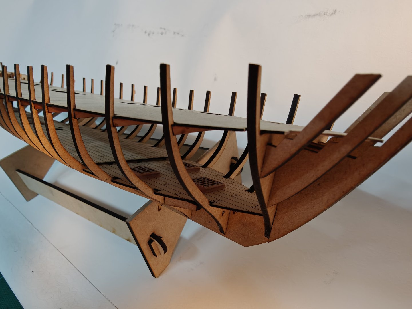
Log entry 1 - building the skeleton I am following roughly the same approach as I have experienced in the few Vanguard kits I have been working on. So I start with attaching the bulkheads to the keel and adding the braces. So far, so good. When using the 4 mm MDF from Amati, I get a very nice tight fit, but with this 3 mm, it is a little on the loose side. I think the material may be a little under 3 mm thick, and I should account for that when designing i CAD, but I have not done so here. It will work ok for this small projet and once the glue was dry, everything was set firmly, but care is needed to not have anything set in a slightly skewed position. I then added the laser engraved lower deck parts and the first pear gratings, also laser cut and engraved. I am very happy with how this looks! It will be almost entirely covered by the upper deck - you may be able to catch a tiny glimpse through the upper deck gratings and the ladder hatch, but it is more about figuring out how to do these things for future projects. I then added the beams to all the bulkheads: I used pear, as I was not sure 3 mm MDF would not just snap when I glue on the upper deck. It looks very nice in pear at this point, but it will all be covered up immediately, as the next (and final for this post) step was to glue in the upper deck base pattern: I had not accounted for the prow pieces, so I had to trim off a few mm at the front of the pattern, but no issues otherwise. So far things are working out. But I can see that the top parts of the bulkheads are indeed too thin. They will not take the load of forming a 1 mm ply bulwark pattern, even if there are many of them! My solution will be to cut out braces for the correct distance for all of them and glue these in. After fairing, I will then form and attach the plywood bulwark (that I first need to tailor) and then remove the upper part of the bulkheads as planned all along. BR TJM


-
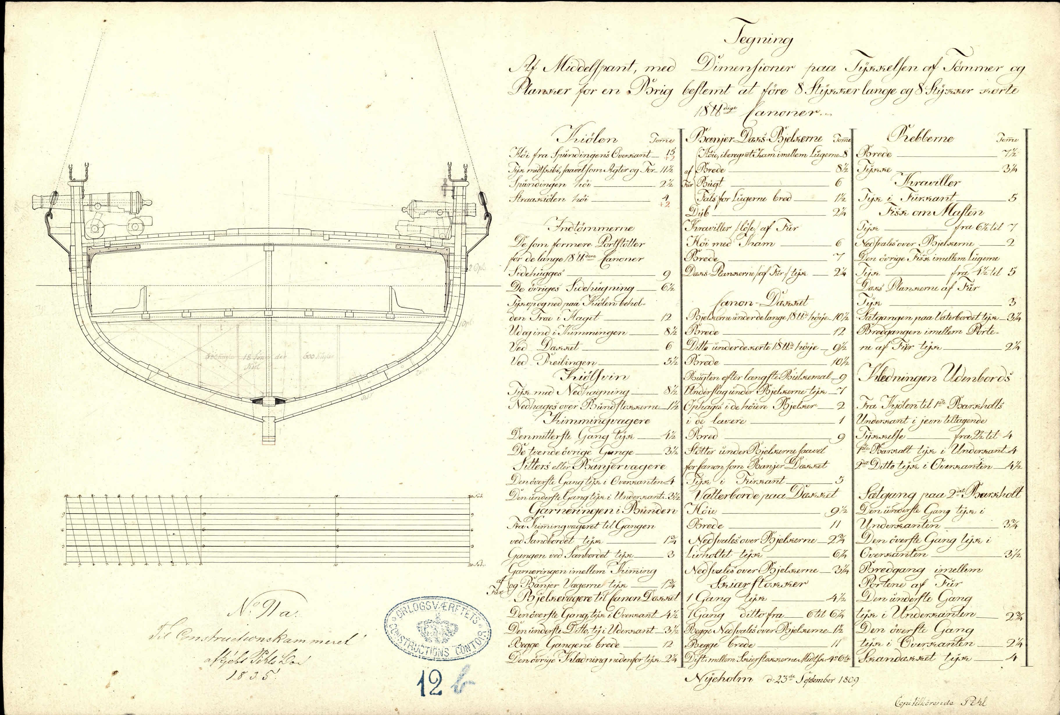
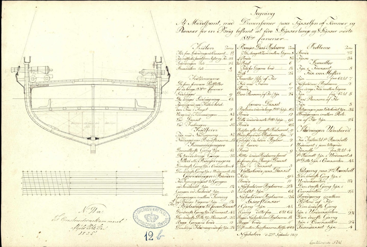
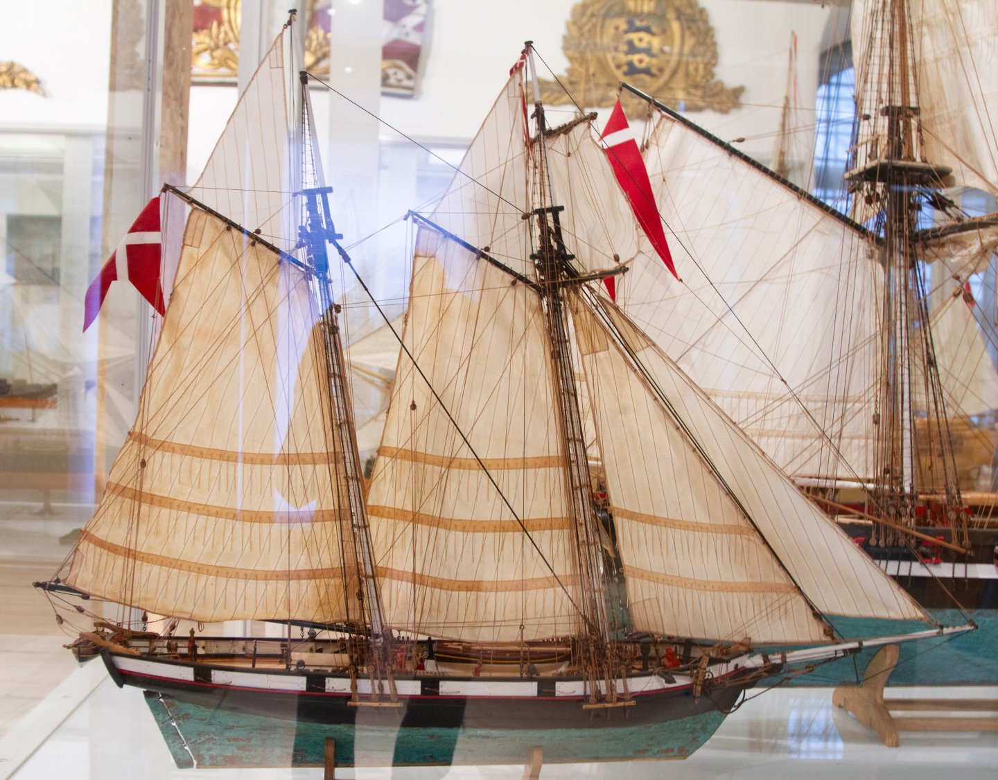
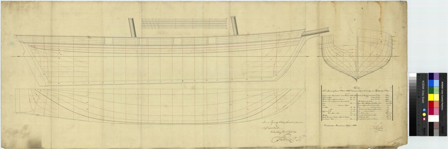
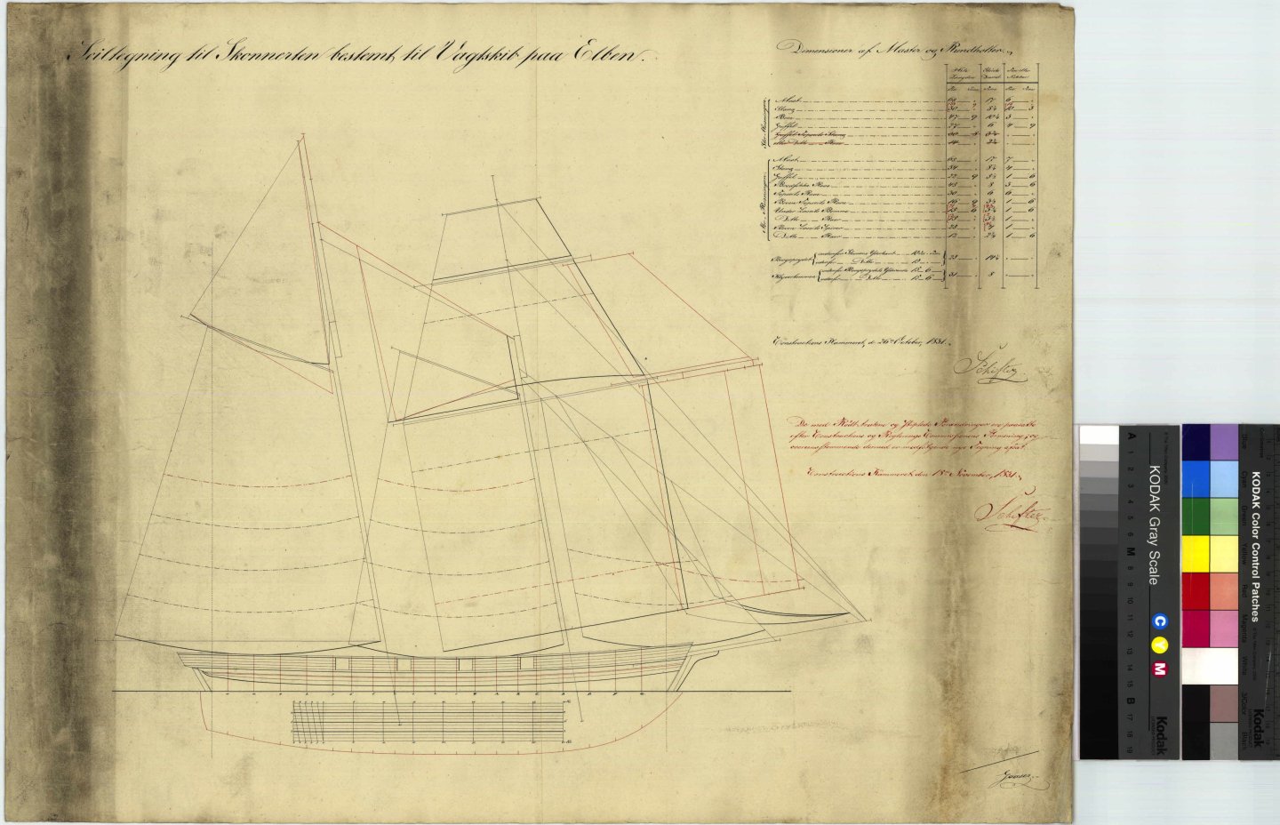
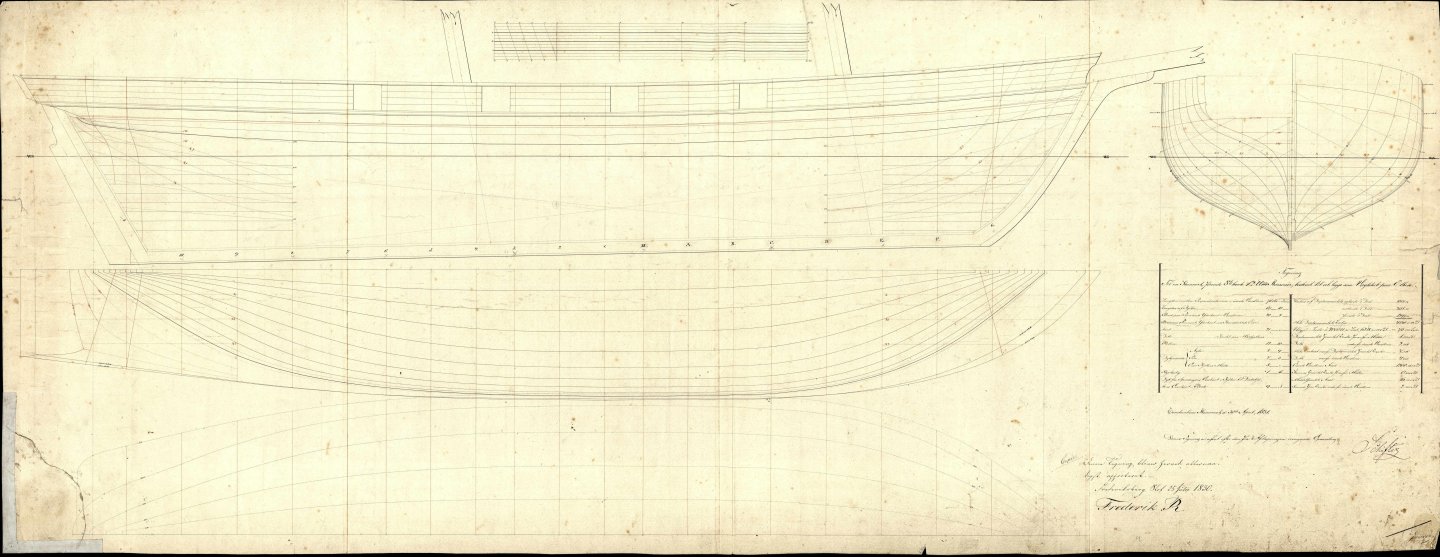
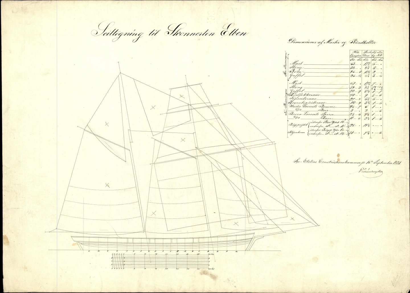
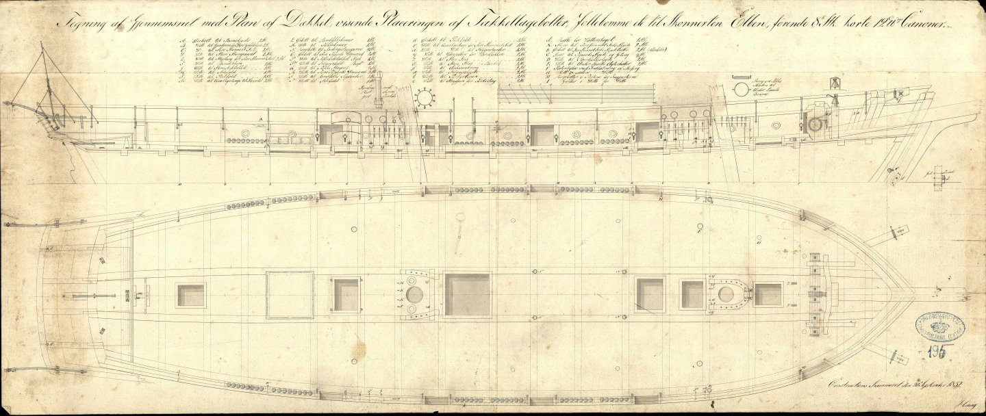
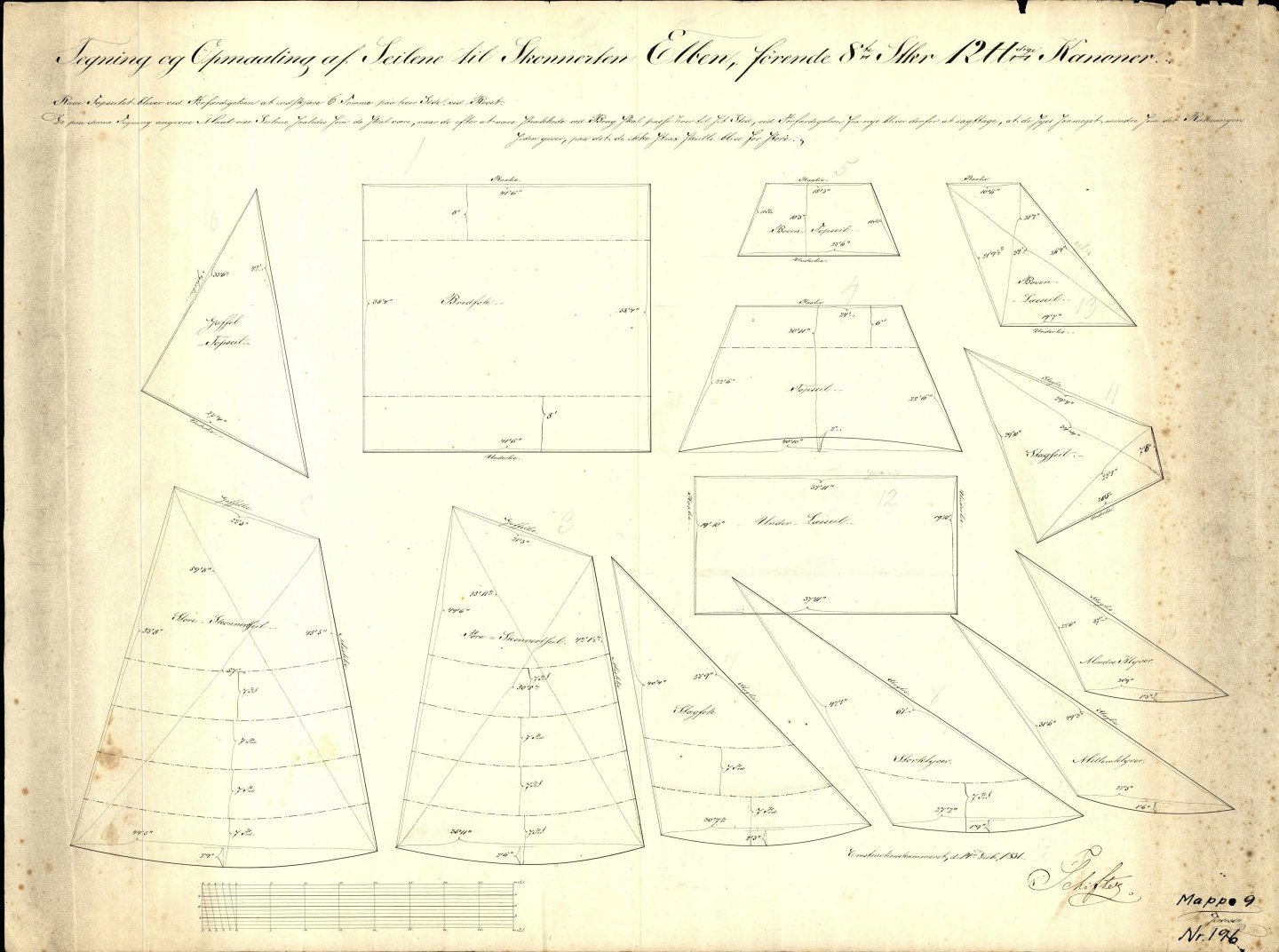
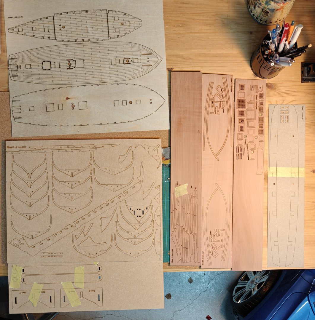
Intro I decided to do this small schooner for a number of reasons: First, it is small. At 76 feet, it is one of the smallest vessels from the Danish archives (apart from ship boats). It does have a little brother named Delphinen that is only 56 foot long, but I found this one to be a nicer overall project. Secondly, it is from a later period - a period that I have somewhat less of an interest in, but I wanted to try something that has a copper plated hull. Being small, I thought it was a good candidate as it won't be too big of a task to copper it. Thirdly, I wanted to learn resin 3D printing and I will use this project to do that, as the armament will need to be customized (very short 12 pounders). An inspiration was the model by Peter Maack at the Danish War Museum of the aforementioned Delphinen: I will take quite a few visual cues from this model. The following are the original drawings from the National Archive. As you can see, this is a small schooner with 8 guns. The guns are short 12 pounders. These were much the same as carronades, but more often used by the Danish ships than actual carronades of the English model. I don't have any drawings of 12 pounders, but I have a few of short 18 pound guns. They were around 10 calibres long, translating into around 121 cm or 1.9 cm at 1:64 scale. Just like a carronade. I really like the drawings of the details on the deck and bulwarks. It should make it relatively easy to make a lot of nice accurate details. Here is an image of the 18 pounders showing both a long and a short one. I will just scale this down to a 12 pounder. After the loss of almost the entire Danish navy in 1807 and the conclusion of the gun boat wars in 1814, the Danish navy had to be rebuilt almost from scratch. It never again became anything close to as large as before the Second Battle of Copenhagen. Inspiration was drawn from many other navies, as had been customary in the past century, but as a new thing, America was now also in scope for that. From there, the Danish naval architects brought back plans for East Coast schooners and a few ships were made withe these as inspiration. They were used for guard duty in ports or on rivers. This particular one was stationed on the river Elben, then still in Danish territory, and named after that river. Adapting the plans via QCAD was quite easy and quick, but I was pushing the thickness (or rather thinness) of the bulkheads and this will probably cause some issues later. It is a bit silly really, as there is no real need for them to be this thin on this build - it is just roughly the correct thickness of the actual frames, but woking with MDF bullheads, I should have added another mm or 1.5 of thickness. Here are the laser cut sheets, 7 in total. The 2 mm one was cut twice, as I had a mistake in the cut file and had one of the parts cut in two. The bulwark patterns are WIP and will need tweaking on the model. This is why they are just cut out of cardboard for now. Now, I will continue with the initial building of the frame of the ship and see how it goes together! BR TJM


-
Hello everyone and welcome to this, my first scratch build project! I have been playing around with my laser cutter for a little year and I am slowly getting to know how to adapt original plans from 18th-19th century into something I can cut out with the laser and assemble. I have been documenting my tests so far here: https://modelshipworld.com/topic/37190-historical-plans-via-cad-to-laser-cut-parts-practicum/ Thanks to everyone who stopped by and who commented and liked the posts there, it is much appreciated. I was doing another small ship plan, trying to push a few things (like laser engraving the decks, etc.) and since the project was small, I found myself with a whole mini-kit of designed cut files, including gratings, beams, decks, etc. And then I couldn't help but try to cut it all out... So instead of continuing my previous practicum, I will start and actual build log here, my first scratch built project! My main project is still Christiania, adapted from the fantastic Vanguard Models HMS Sphinx kit, and it is likely ill advised to start on a new (albeit small) side project, but I feel I have exhausted what I can get from just designing and making the frame of ships for 'scratch built training' - I have to actually try to assemble and plank something to continue to the fittings stage of the design process. Especially the plywood bulwark patterns need tweaking that I can't do off model, so I need a faired hull to work out how to best make those parts. Christiania will continue as my main project but while I slowly get the planking finished on that, I will work on this project along side it. The next few posts will be a presentation of the ship in question, a small schooner used as a guard ship on the river Elben - Elben also being the name of the ship itself - and then the initial assembly of the frames. I hope many will stop by and give their input along the way - the conversations on this forum is a large part of the hobby to me, and I really appreciate all the great feedback I get here! BR TJM
-
The very best of luck with this project, I am sure it will be great! And I will follow your journey with great interest!
-
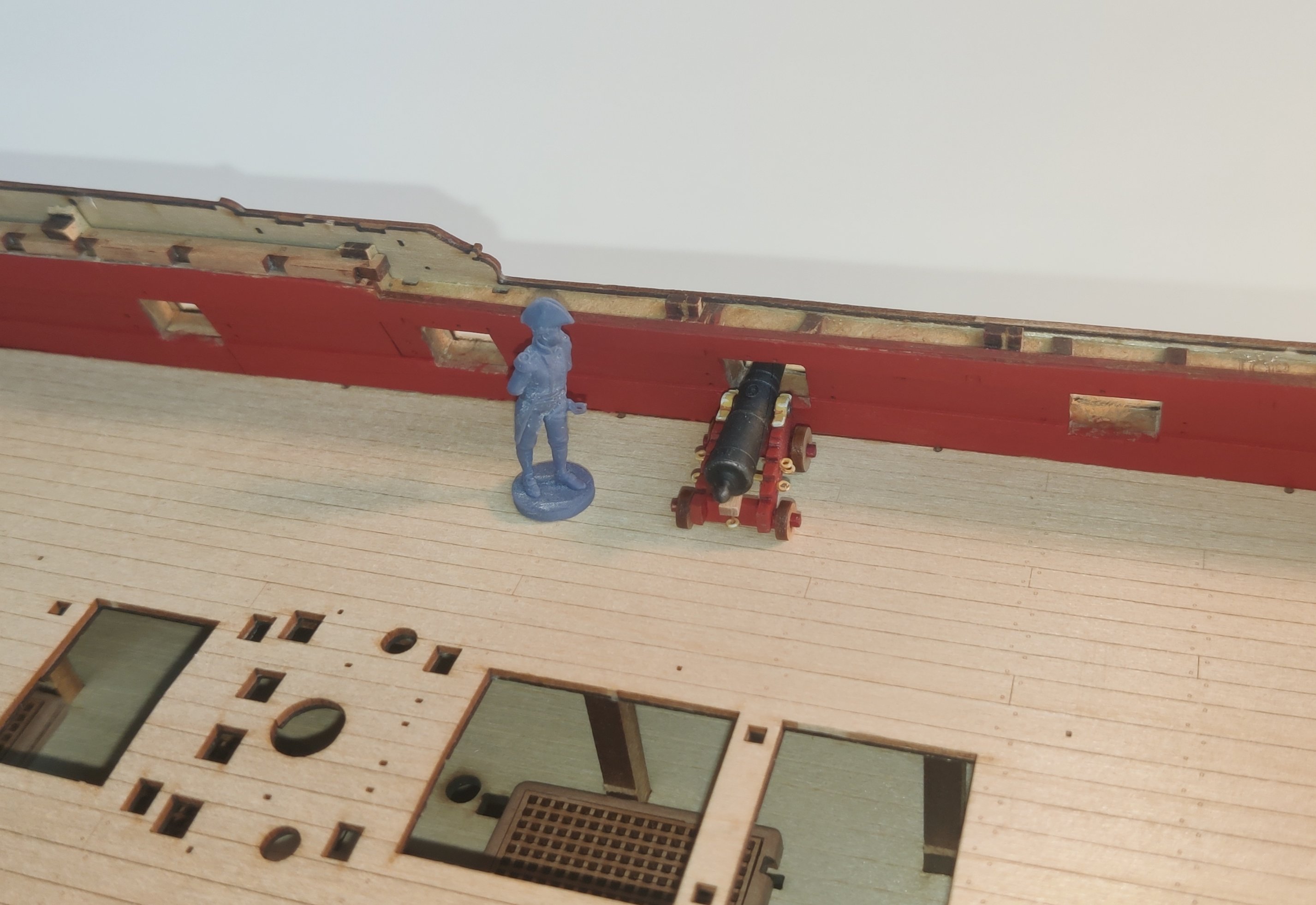
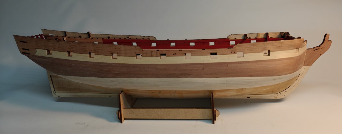
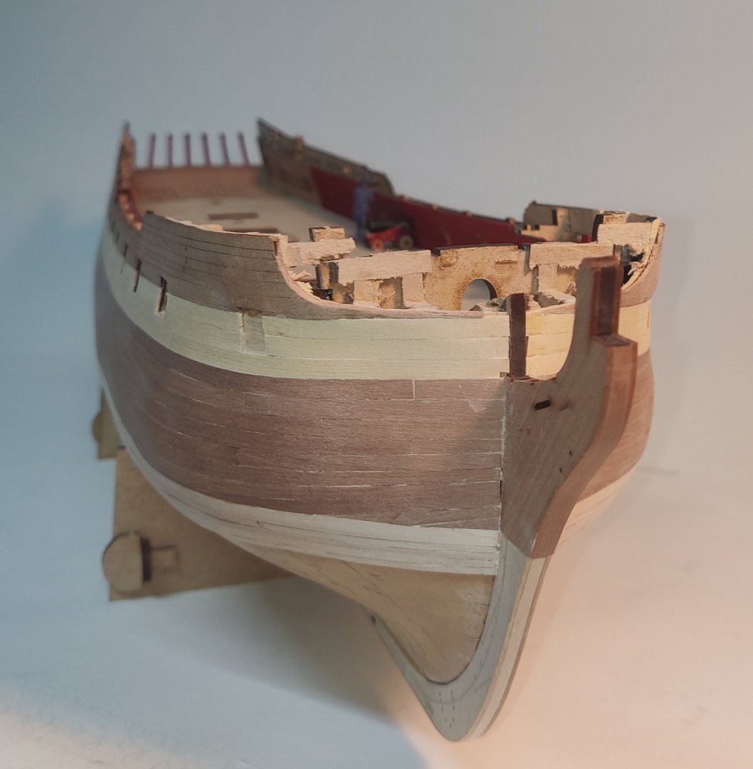
Log entry 22 - a bit more planking and painting the inner bulwarks I have added a few more planks and I think it is starting to show how it will look when completer. 10 planks down, 40 to go... And as I had decided to paint the bulwarks red, I masked off everything and did so - no mishaps or paint seeping, so that's nice. Here is how it looks now, with Kaptajn Hornblæser (I guess he got promoted.. ) inspecting the paintwork and how it goes together with the cannon paint sheme: As you may be able to tell, I am rough sanding as I go. I find it easier to control with a few planks at a time and it makes for less sanding at the end and (I hope) less likelihood of sanding through the second planking, as I only take off just what is needed initially. BR TJM


- 148 replies
-
- 10
-
-
- Christiania
- Vanguard Models
- (and 1 more)