HOLIDAY DONATION DRIVE - SUPPORT MSW - DO YOUR PART TO KEEP THIS GREAT FORUM GOING! (Only 13 donations so far - C'mon guys!)
×


Decoyman
-
Posts
97 -
Joined
-
Last visited
Content Type
Profiles
Forums
Gallery
Events
Everything posted by Decoyman
-
 Thanks for the advice everyone. I'll rescue a couple of pieces and put them in the store. Rob
 -
We will be cutting up and disposing of a large fallen poplar tree at the school where I work next week. This is the European poplar - very tall and slender - not the North American variety also known as tulipwood. Does anyone have a view on whether it is useful for ship modelling, case construction or any other purpose related to our hobby? Rob
-
If you are working from a lines drawing then what you have are the profiles of the outside of the frames. There is no need to adjust the lines to allow for the thickness of the planking. Having said that, if you are going to double-plank the hull then you may need to make adjustments as the total thickness of planking could be greater than the prototype. Regards Rob
-
I thought my explanation of how my alternative tick strip method works could do with some illustrations.... TickStrip 01.pdf TickStrip 02.pdf TickStrip 03.pdf The first drawing shows the diminishing grid as it is supposed to be used: the tick strip is parallel to the setting-out line and the ticks are equal. The second drawing shows the diminishing grid used wrongly. You can see the tick spacing varying along the length of the strip. The third drawing is my alternative. Any strip length can be used and all you have to do is adjust the angle until the ends of the strip are a pair of lines the required number of spaces apart. The only proviso is that the line spacing should be less than the maximum plank width. In each case there are 20 spaces along the length of the strip, representing 20 strakes of planking.
-
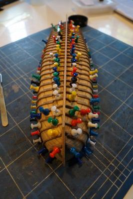
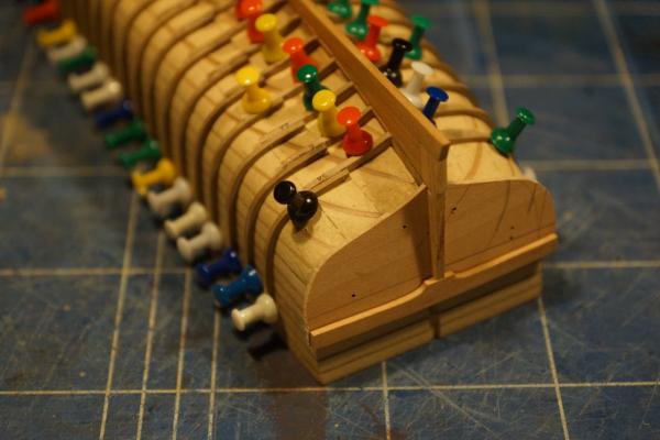
Thank you all again for your kind comments and likes. You made me feel inspired enough to find time to do a bit more! I have made and fitted the first strake of planking either side of the keel. This is the first time I have attempted spiling of planking. So far it's OK... I have had to remake one strake through impatience, and the fit of each is not quite as perfect as I would like. The following photos show the garboard strakes being glued in place. I will post some more once I have several done. The last photo shows the stern. You can see the ends of both strakes and the tick marks I put on the frames to define the widths of the planks. You can also see the stern planking, where I was a bit dim with the choice of wood! It's all cherry, but the first three planks are noticeably different in colour. I am hoping I can tone the variation down when I apply a finish. In case anyone is wondering I emphasised the joints between planks by rubbing both edges with a 2B pencil before glueing them in position. I think it's reasonably subtle. Another thing worth mentioning, since I don't remember finding this point made anywhere else, is how to measure the tick marks quickly and easily. Most people cut strips of paper to the length of the frame between the keel and the wale, which is what I did as well. However it is usually suggested that the next step is a diminishing grid: a 'fan' of lines drawn from a common point and with the other ends set out equally along a straight line. Sufficient line are drawn so that the number of gaps between lines is the same as the intended number of strakes of planking. The idea is that you lay your strip of paper across the grid at a position where the ends of the paper just touch the outermost parts of the fan. You then mark off along the strip the intersections between the lines of the fan and the edge of the strip. This gives you a strip subdivided equally by the number of strakes. It works fine, providing you keep your strip parallel to the line used originally to set out the fan ends. If you put the strip at an angle then the spacing will vary. I prefer to use a simple sheet of lined paper - it can be graph paper with a square grid, but ordinary ruled notebook paper works just as well. You need to place your paper strip at an angle across the lines such that each end is exactly on a line and the number of spaces between the two lines at the ends of the strip equals the number of strakes. then mark off the intersections as before and the strip will be evenly divided. Both methods are similar, but my method is quicker, because you don't need to make the diminishing grid, and there is a little less opportunity for error. Rob

-
Thank you all very much! Rob
-
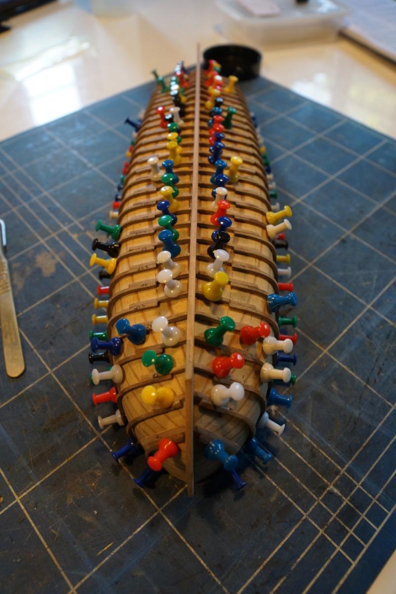
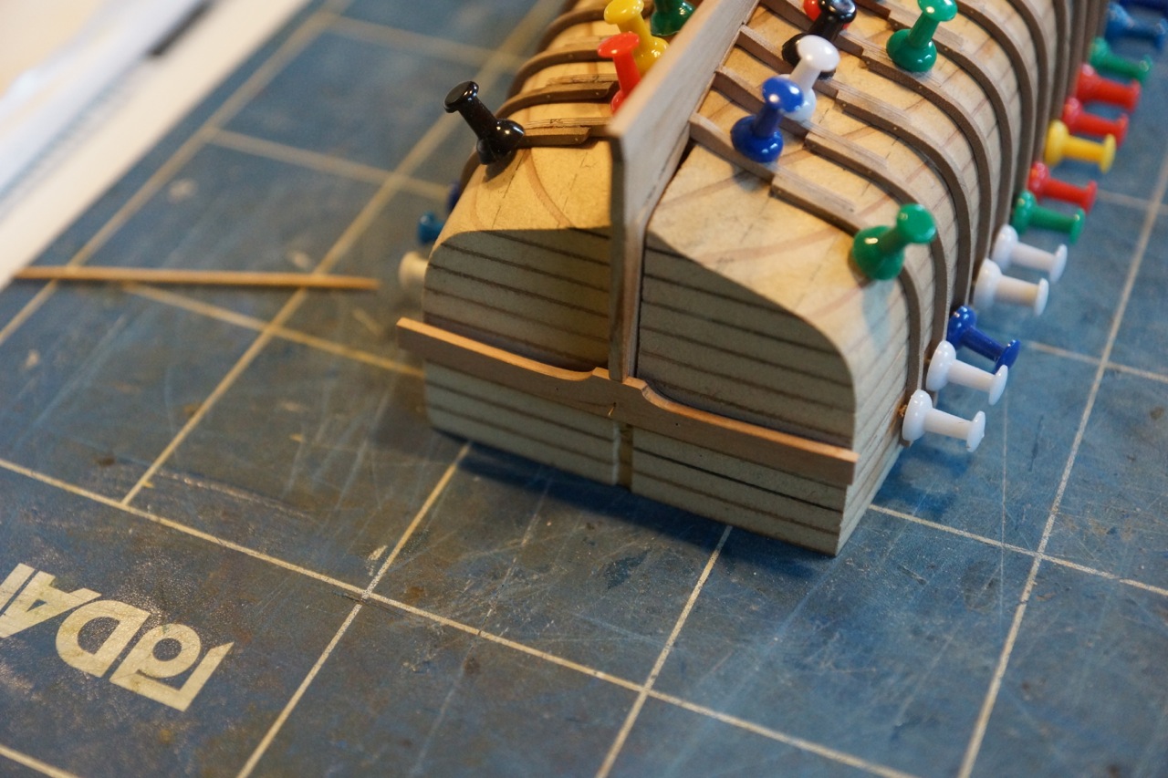
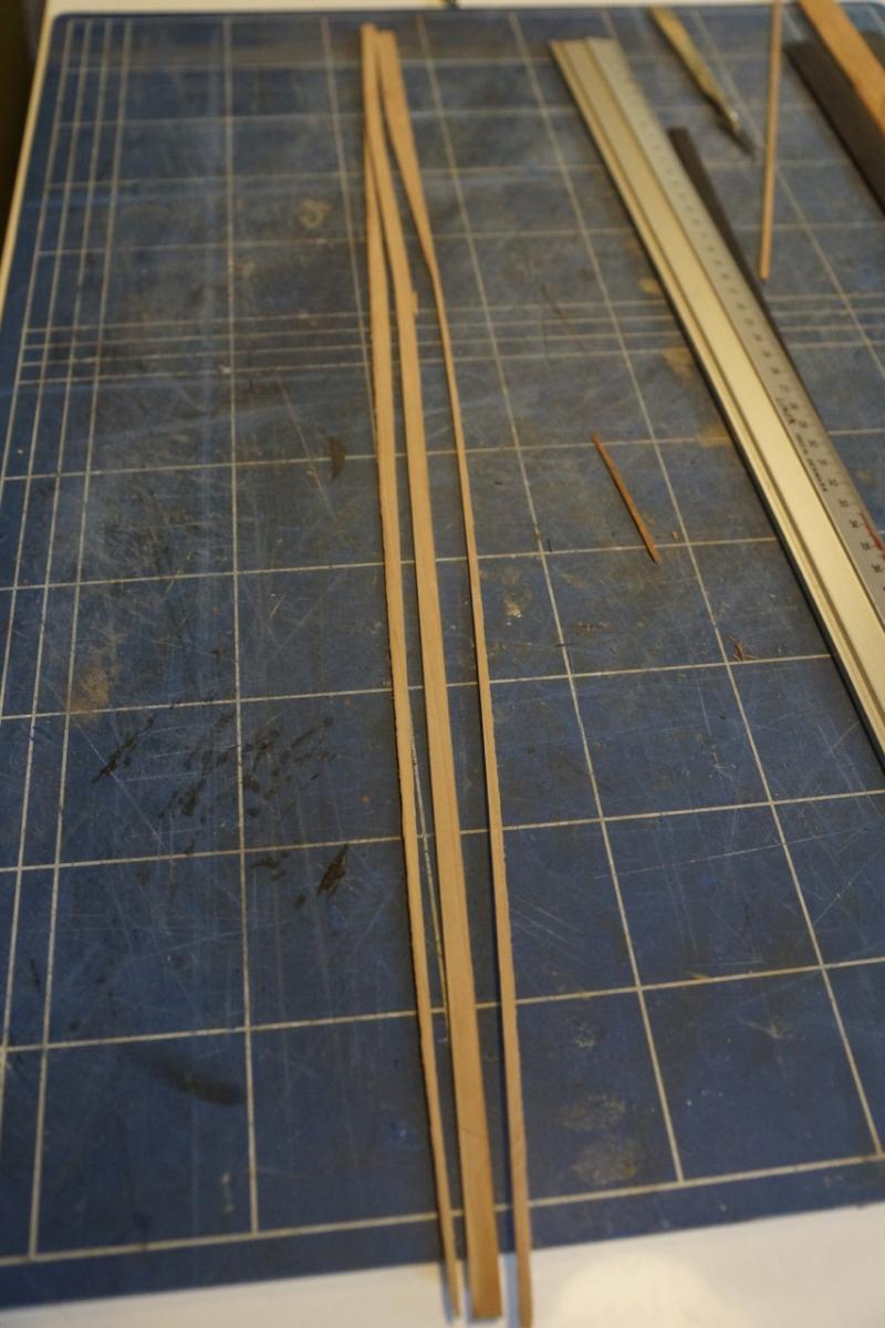
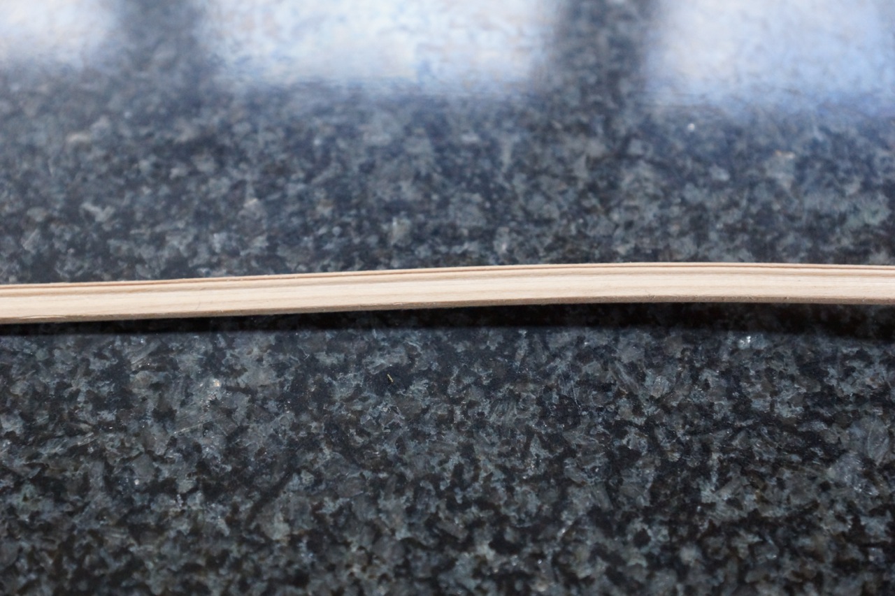
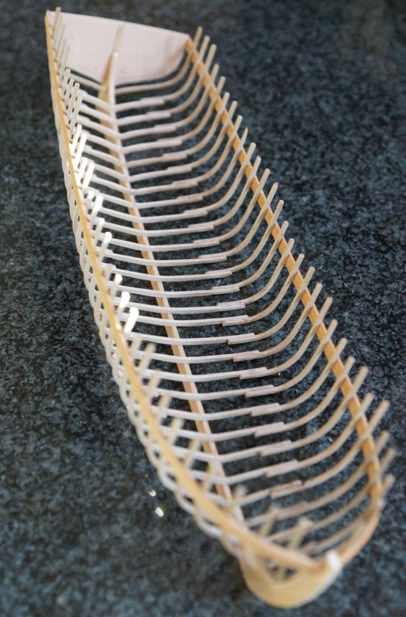
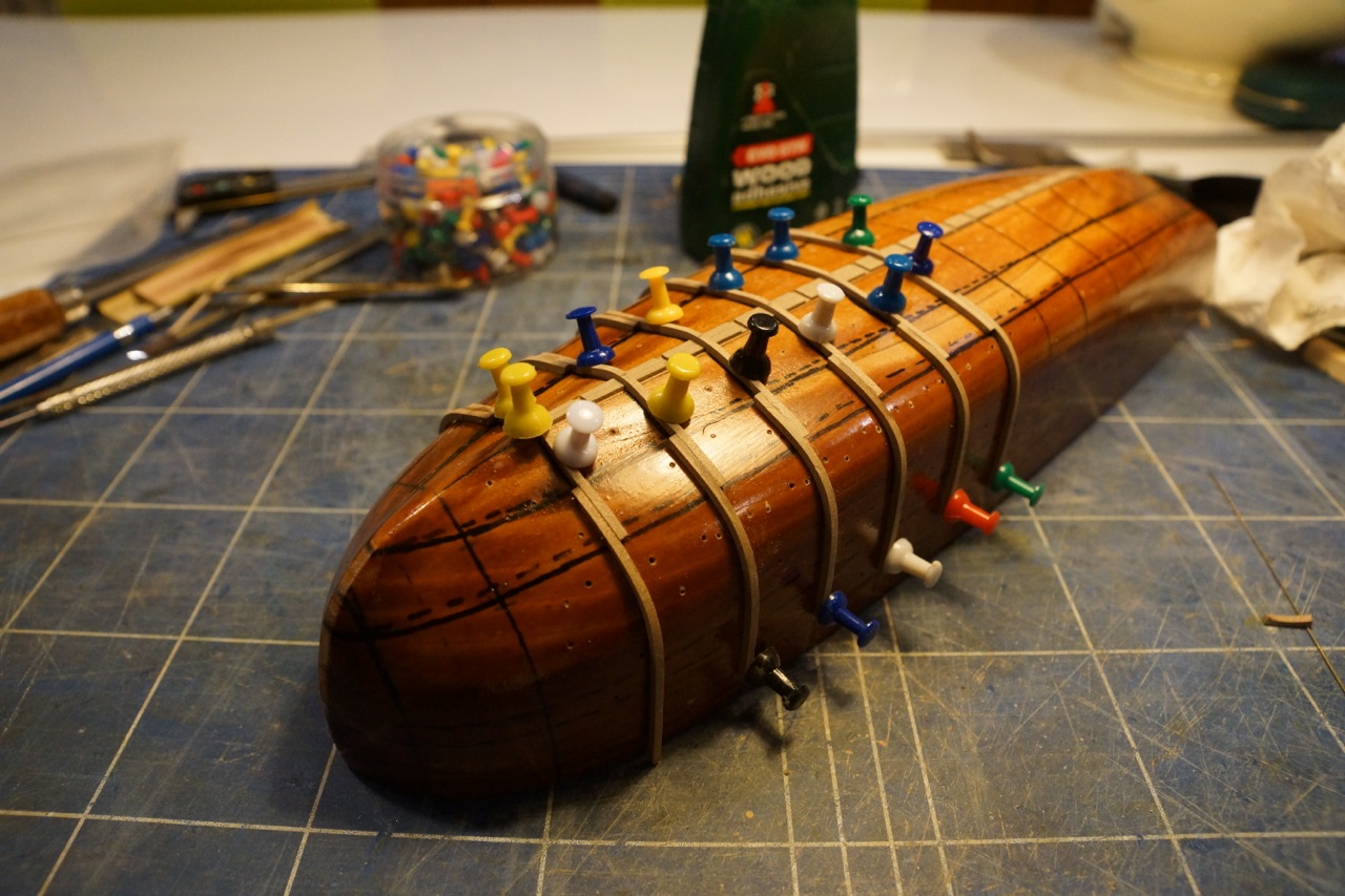
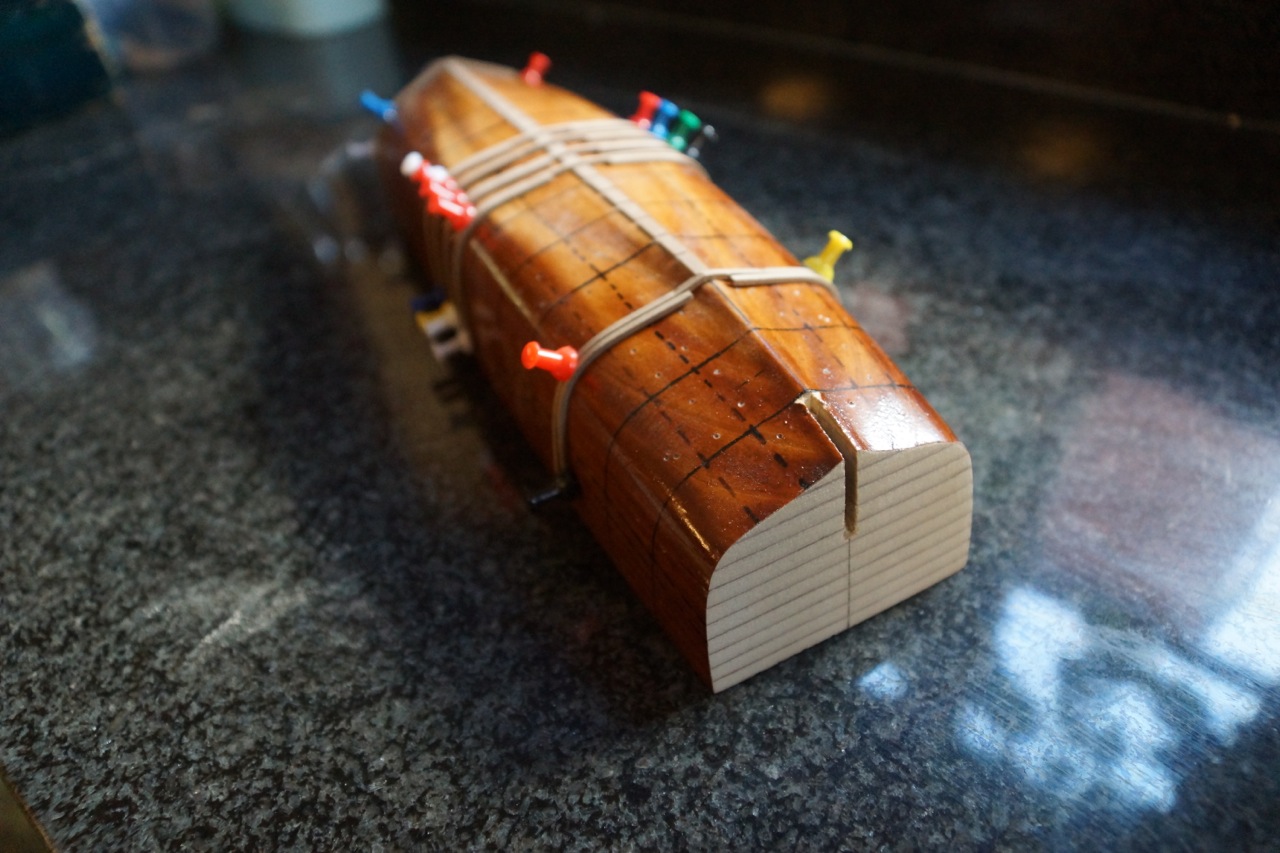
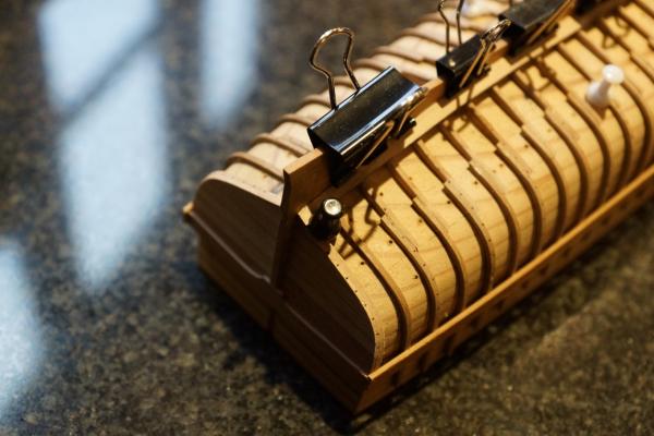
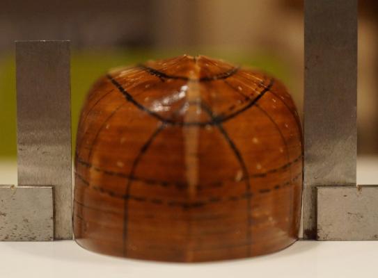
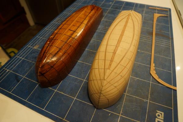
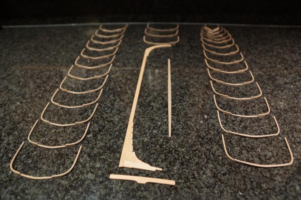
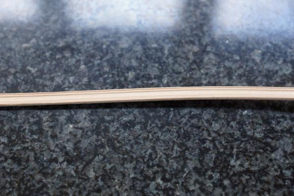
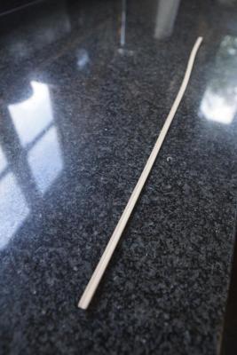
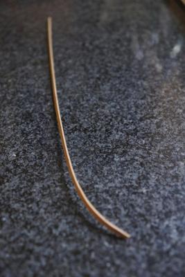
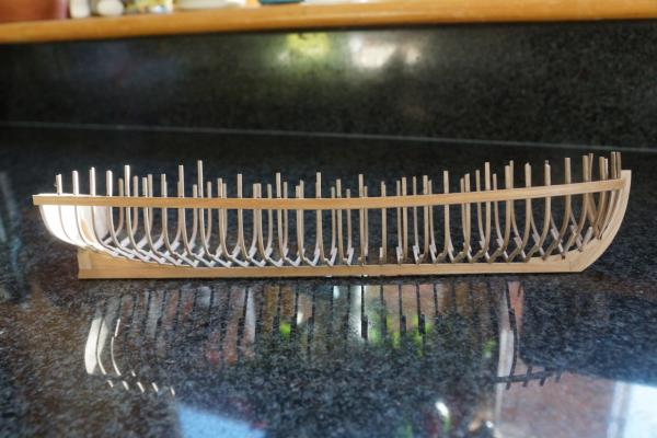
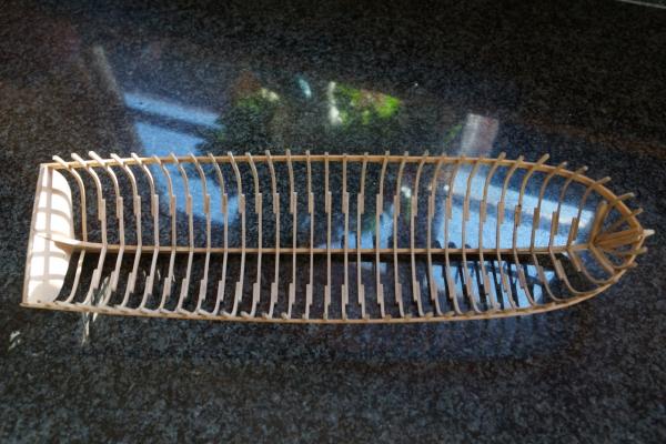
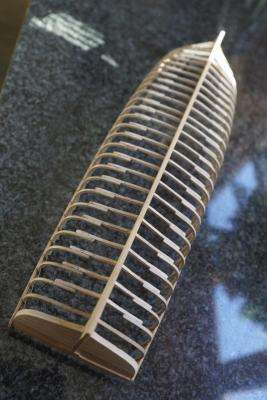
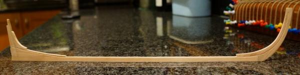
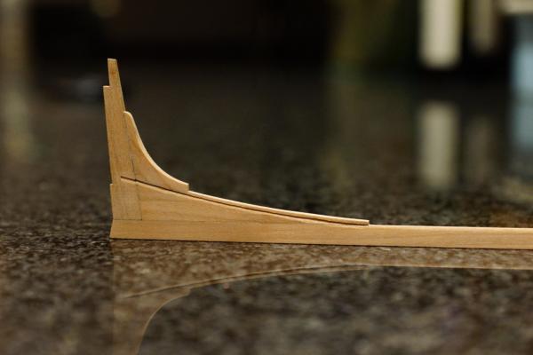
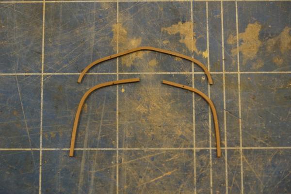
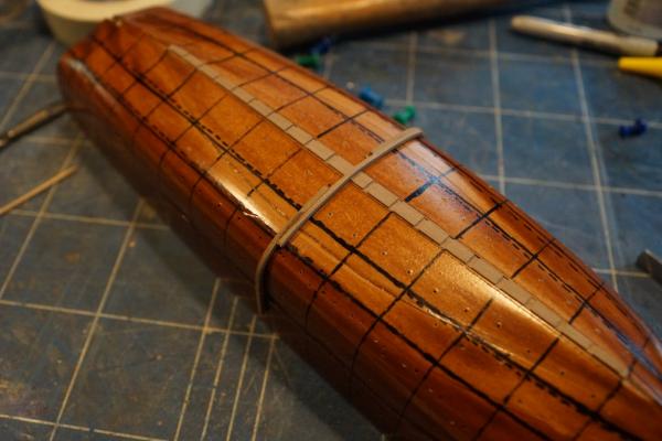
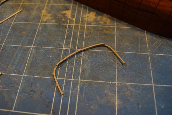
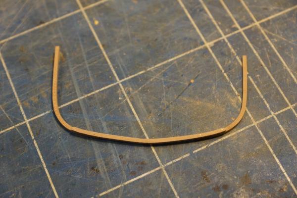
As you may have noticed I have not made any posts for a while. Pressure of work and now a new job have all made work on my chaloupe nigh on impossible, sadly. I do have some progress which I have not yet reported on and in which you might be interested. Since my last post I have faired the frames as far as possible. Here are a couple of photos: However at this stage I began to think something was wrong.... It took me a while, but after much fiddling trying to get the keel, stem and stern posts aligned to each other and square to the mould, I realised that the mould itself was not true. This photo shows the problem: I think that the stack of MDF laminates was able to slide sideways at the point while the glue was still wet and I was tightening the clamps. I considered sanding the sides square, but concluded that this would only lead to a misshapen mould. So I made a new one, taking more care this time to ensure everything was aligned properly. Here are the two moulds side-by-side. The differences are not obvious, but the second one is unquestionably more accurate. Because I had not glued anything to anything else at this stage (with the exception of the floors and futtocks making up each individual frame) I was able to unpin everything from the old mould and re-fix it to the new one. Although the frames had been made over the old mould they fit the new one well enough, so in the end there was not much other than the mould to redo. So now I was able to make proper forward progress with the transom. You can see the top piece in the picture with all the frames above. This pinned nicely to the back of the sternpost and square to the mould. The next step was to fix two pieces of thin (1.5 mm) ply, roughly profiled to the shape of half the transom, to each side of the stern post, tucked under the top piece. These were pinned in place until the glue was dry. The outer profile was sanded using a round sanding stick running across the last few frames. The outer surface of each side of the transom was boarded with 5 x 1 mm cherry and again the ends were sanded to the correct profile. The final pieces of progress are the two wales. These needed spiling to the correct longitudinal shape and then profiling in section using a scraper filed into a piece of scrap brass. Once they were soaked and curved to the right plan form they could be glued in place. At this point the framework is strong enough to remove from the mould as you can see. And that is nearly as far as I have got to date. I have made the two garboard strakes, but they are not finished yet or fitted. Hopefully I will get some more time soon! Thanks for reading. Rob


-
Simulated caulking
Decoyman replied to Nirvana's topic in Painting, finishing and weathering products and techniques
Haven't you guys got your scale conversation in the wrong topic? -
There are some useful pictures here: https://picasaweb.google.com/Portchieboy/VictoryReference?authkey=Gv1sRgCOSnmbSV56rtLA These images https://picasaweb.google.com/Portchieboy/VictoryReference?authkey=Gv1sRgCOSnmbSV56rtLA#5319055538931717202 https://picasaweb.google.com/Portchieboy/VictoryReference?authkey=Gv1sRgCOSnmbSV56rtLA#5319055461142235954 https://picasaweb.google.com/Portchieboy/VictoryReference?authkey=Gv1sRgCOSnmbSV56rtLA#5319055513781978834 https://picasaweb.google.com/Portchieboy/VictoryReference?authkey=Gv1sRgCOSnmbSV56rtLA#5319055538931717202 https://picasaweb.google.com/Portchieboy/VictoryReference?authkey=Gv1sRgCOSnmbSV56rtLA#5319055563828892338 all seem to confirm your initial assumption. Hope this helps. Rob
-
I think I need to have one of these clamps in my hand to really understand! As I see it the two screws are not interlinked, so whether they open or close 'their' end of the clamp depends solely on the direction they are turned, not the direction of the thread. The reason I am interested is that buying taps and dies for LH and RH threads is expensive and you will rarely need the LH set after you have made your clamps. If the clamps can work with one thread type only then the job is simpler and cheaper. Sorry for persisting, by the way. [EDIT] I think I understand now - each screw has one end with a LH thread and the other end RH. I assumed that one end turned in a kind of captive collar in one jaw so that the other jaw moved up and down on the threaded part. Silly me!
-
Thanks Ed, I can see that the two screws allow independent adjustment of the ends, I just don't understand why they have to have opposite threads. What am I missing? Rob
-
Hi Ed, Could you or someone else explain why the threads on the two clamps need to operate in opposite directions? Regards Rob
-
As far as I understand it all the drawings are based on CAD originals. In which case why not charge a fair price to issue reprints of the drawings separately, either as a package or individually? Builders could request them to be supplied at particular scales, not just the one chosen for the book. For a higher price you could provide PDFs which the builder could print themselves, either in whole or in part, again to whatever scale suited them. I can see why you want to protect your copyright, but the sad truth is that anybody who wants to can ignore it with impunity. What's more I would suspect many people needing to make copies of your work to be able to build a model will already have bought your book - haven't you therefore already been paid for your intellectual effort? My copy of the Delacroix monograph on the Chaloupe Armee en Guerre from Ancre specifically suggests copying the plans to help with the construction of the model. Best wishes Rob
-
soldering wire to brass
Decoyman replied to MikeB4's topic in Metal Work, Soldering and Metal Fittings
Soft solder at the scales we work in will work as well as silver soldering and, I suspect is easier to do. The key is to ensure all surfaces to be soldered are spotlessly clean. I scrub mine with a fibreglass pencil. Then I use a liquid flux touched in on a brush at the point where the joint is to be made. Since we are only making small joints I find it easiest to carry the solder to the joint on the tip of the iron. Hold the iron in place while the flux boils away and make sure all the parts of the joint are heated through. Once this has happened remove the iron and continue to hold the components in place until the solder solidifies. You should find you have made a good solid joint. The excess solder can be removed using a scalpel and needle files. Another scrub with the fibreglass pencil will polish away the last bits of spare solder leaving a neat job. Afterwards you must make sure you wash whatever you have been soldering in clean water to remove any traces of flux. If you don't do this the surfaces will become corroded over time. The hardest part of the whole process is growing the extra hands with the asbestos fingers so that you can hold everything in place at the same time. -
What method do you use to get those neat black lines between your planking? Do you use the same system for the deck and for the hull? Rob
-
No rich uncle I'm afraid. If there was one I'd be first in the queue. You don't need to turn the blank down to fit in the chuck - just drill a hole in the centre, run a screw in and cut the head off. You can hold the smooth part of the shank of the screw in the chuck. Rob
- 421 replies
-
- 2
-

-
- granado
- bomb ketch
- (and 2 more)
-
Gerard Delacroix, in his instructions for his Chaloupe Armee en Guerre, outlines a method of turning a cannon using 'standard' electric drill (not a mini-drill), two trestles, a length of broom handle, a 40 x 60-80 mm block of wood and a 2.5 mm nail. You will also need some bungee-type elastic luggage straps. He used these bits and pieces to turn a cannon about 85 mm long and 15 mm in diameter, not dissimilar to your dimensions. Essentially the first trestle forms a stand for the drill, which is held on using one of the bungees. The nail is driven into the wooden block at the centre-height of the drill above the trestle. The second trestle is placed alongside the first and the broom handle strapped to it. This forms the tool rest for a chisel, to be used to shape the cannon. You fix the timber blank for the cannon to the drill chuck using a screw run into one end and with its head removed. The nail in the block locates into a hole in the other end of the blank. A third bungee holds the block with the nail to the first trestle and then you have a rudimentary lathe. Delacroix used beech dowel for his cannon. I haven't decided what to use myself, but I do have some decent chunks of ebony, so I might try one of them. I will probably also have a go with brass or possibly steel, since I do have a small Cowells lathe available (sorry). Regards Rob
-
Thank you! Rob
-
Is it www.shipmodels.ru we should be looking at? because I can't see a link for 'accessories". Rob
-
I sanded the exposed faces using 180 grit (fine) sandpaper. The dilute PVA soaks into the wood and holds the pieces together. Once it's dry it looks the same and sands the same as normal. Rob
-
Dear Everyone! I haven't completely abandoned this log, but my mind is a bit preoccupied with my new project (see my signature). Some of you may be interested to know that Agamemnon will be on display at the forthcoming Model Engineer Exhibition at Sandown Race Course in Surrey from 13-15 December (assuming I can find a way to move such a big and fragile model). You can find out more about it at http://www.modelengineershow.co.uk. I'm also pleased to say there is a photo of her in the current edition of Model Engineer - fame at last! Kind regards Rob
-
HMS Naiad 1797 by albert - FINISHED - 1/48
Decoyman replied to albert's topic in - Build logs for subjects built 1751 - 1800
That's beautifully neat work. What timber are you using - is it pear? Rob -
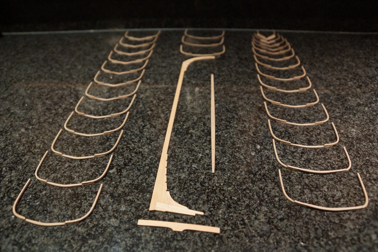
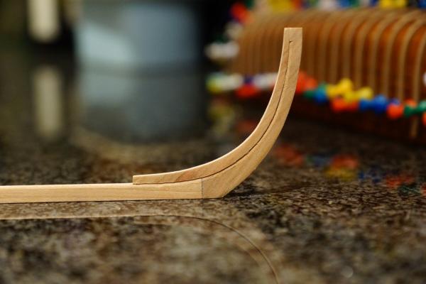
Thanks for the support and the likes everyone! I have cut the planking rebates in the side of the keel assembly. I used a couple of different scalpel blades: a small straight to cut the inside of the chase and a large curve-ended one to scrape it clean afterwards. Mostly however I used a small V-profile gouge with a very sharp edge. This cuts beautifully and I'm almost happy with the result. The only disappointment was that my very last cut was a wrong'un! I forgot to stop the rebate on the stem and ran it straight out the top. I haven't shown this in the photos below (still feeling slightly annoyed with myself…). My only thought so far is to cut the profile of the short section of extended rebate as neatly as possible and then piece-in a very small sliver of cherry. If anyone has a better idea I'd be pleased to hear it. I have also made the last frame components. The crutches are over-deep so they can be sanded to shape once the frames are assembled. Rob
-
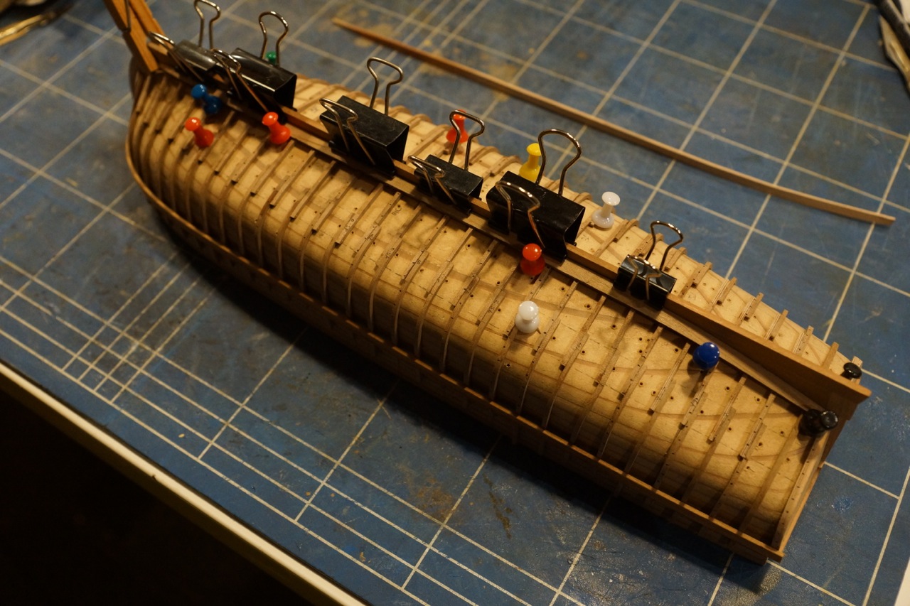
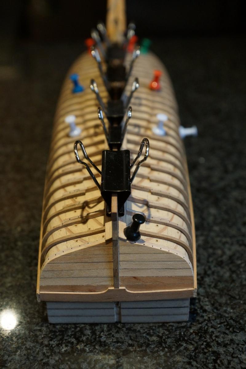
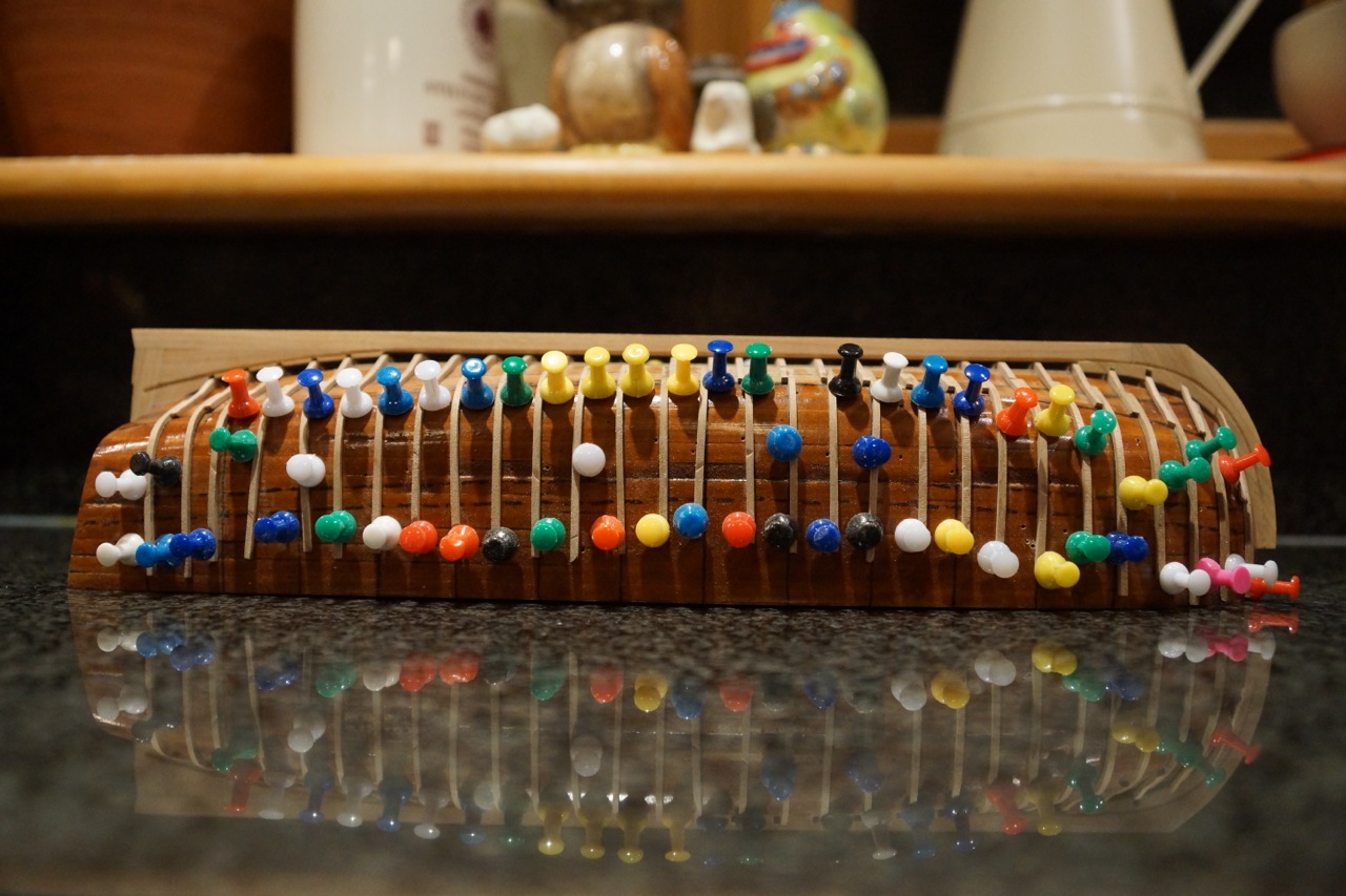
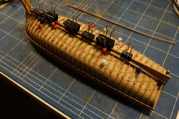
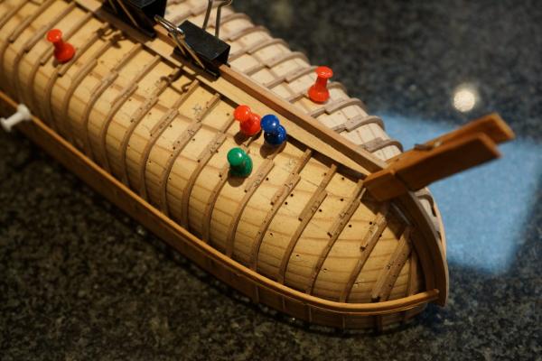
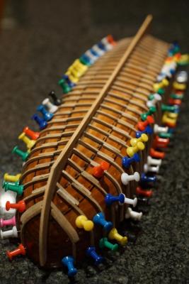
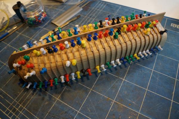
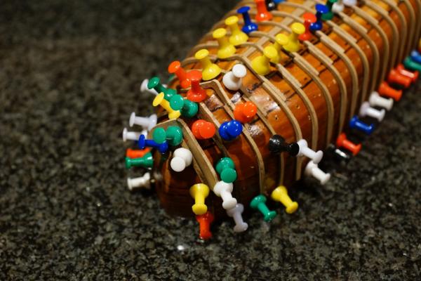
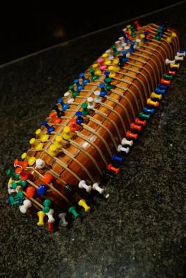
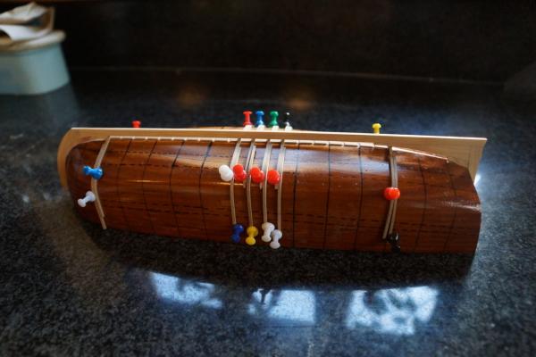
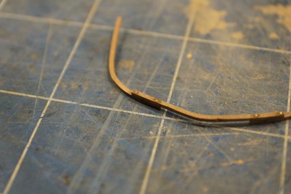
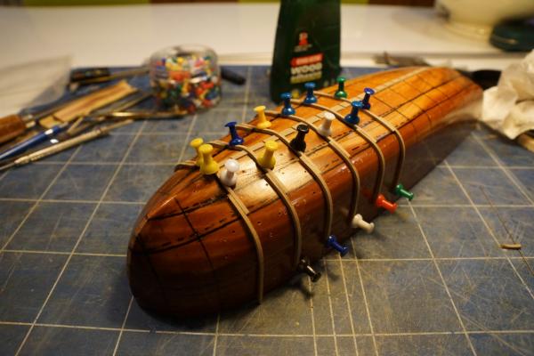
As I suggested in my last post I needed to sand off the end of the mould so that the keel assembly fits properly. This was hard work, but pretty straightforward. As you can see in the following pictures the keel now drops over the frames with no problem. The next issue was how to stop the frames sticking to the mould when the components were glued together. I took all the frame parts off the mould and gave it another good polish. Then, starting at the MC position, I assembled each frame over the mould, glueing the futtocks to the floors with medium cyano and using the pushpins again to hold everything in the correct relationship. Once the glue was reasonably dry I removed the pins and then the frame. If the frame was stuck I held a piece of wood against the side of the joint and tapped gently until it popped off. Once or twice a frame became glued quite firmly and a bit of the mould came away stuck to the inside. The MDF is actually quite soft, so can be removed easily, and it is certainly better for a bit of the mould to be stuck to the frame rather than a bit of frame stuck to the mould. Occasionally the futtock/floor joint was a bit dry and came apart, in which case I just put everything back on the mould and re-glued the joint. The small dots on the sides of the floor and futtocks mark the glued faces. The next step was to drill through the frame joints twice each and insert short lengths of 0.5 mm brass wire. These represent the bolts used on the prototype and also strengthen the joint because they are glued in. Once these were dry I trimmed the over-length floors and futtocks using a razor saw and then rounded off the upper corners in each case. Finally I sanded all the exposed faces, making sure there were no traces of glue left around the joints and the ends of the bolts. The finished frames were put back onto the mould and pinned in place, making sure the sides were vertical. I made every other frame to start with so that I had more working room. I haven't quite finished the frames yet - there are three still to do. Next time: making the rebates in the sides of the keel and finishing the frames preparatory to fitting the keel. Rob


-
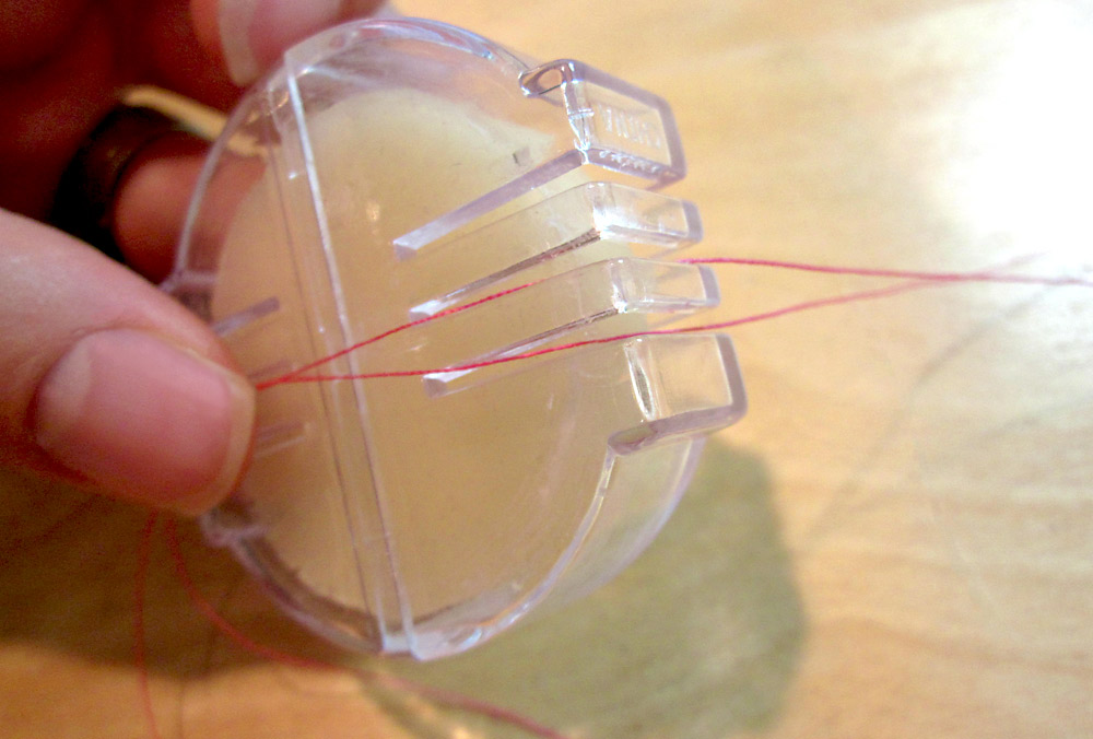
Sewing shops sell beeswax in a little plastic containers with slots. Like this: You drag the thread through the slot and across the surface of the wax. Easy! Rob