SJSoane
-
Posts
1,648 -
Joined
-
Last visited
Content Type
Profiles
Forums
Gallery
Events
Everything posted by SJSoane
-
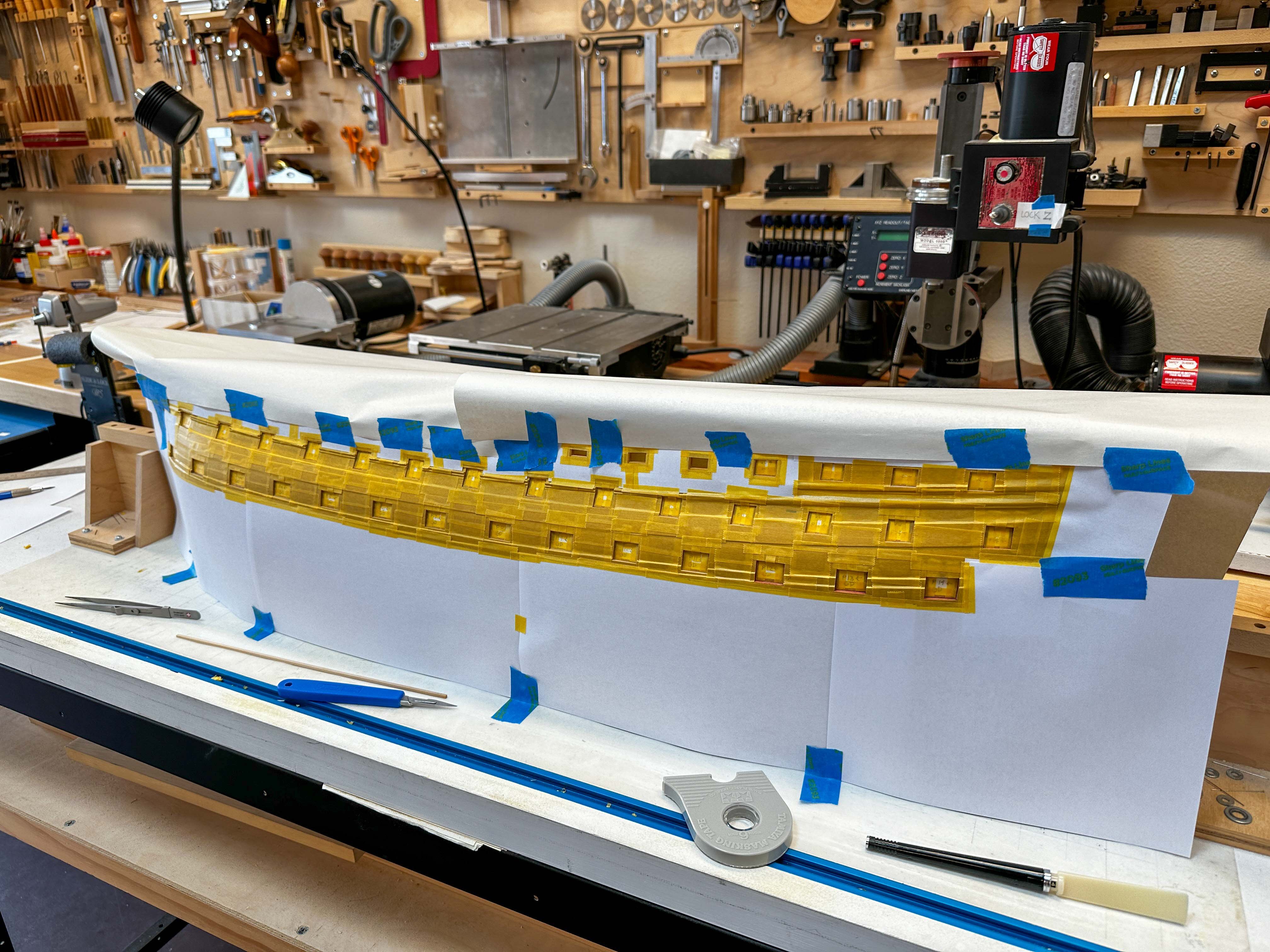
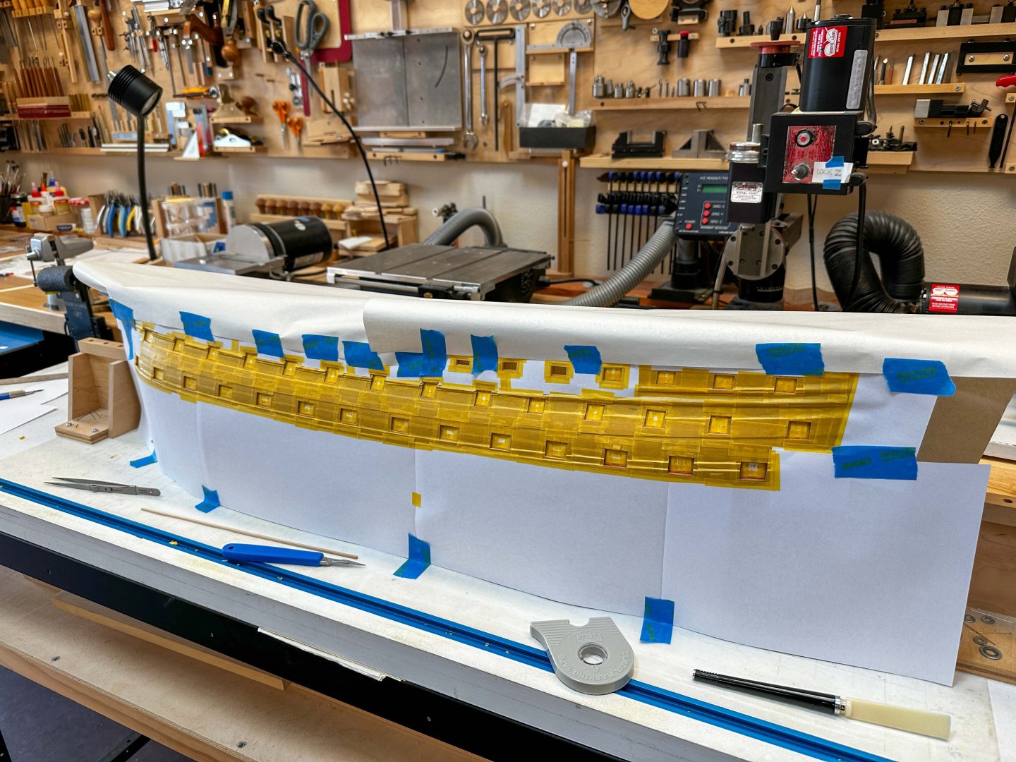
 Druxey, I have been pondering the same question; how did these stern structures come about? I am no nautical historian, but just looking at ships from the previous century the structures were significantly different. So someone decided they needed updating! Although we are so used to seeing the mid eighteenth century sterns that they seem natural and inevitable, the most curious part for me is the quarter gallery curving to the hull at the fore edge, leaving a thin and useless wedge of room inside as one moves forward within it. Who thought that was a good idea?🤨 Thank you Mark and Marc, I always appreciate your kind thoughts--they keep me going when I don't always feel like working! I have been very slow in progress lately, although now working every day for a good part of each day. I ran into one of those: "ok, I will do X; wait, before I can do X I need to do Y; and before I can do Y I have to do Z..... The next step in the quarter gallery construction is to glue the lower finishings in place, so I can begin to built up the structure from that foundation. But before I can glue the lower finishing in place, I need to paint the black main wale, which the lower finishing sits upon. And just when I was taping out the black wale, I realized that the gun ports at the stern cut deep into the wale, revealing a thick edge of wale around the port. What color is that, I wondered? After looking at the Bellona second model, I realized that the edges of all the ports are painted red, right out to the face of the planking. I had left the edges natural. So, wanting authenticity, I had to paint the edges of all the ports red before I could proceed. And then the fun began. Almost 20 years ago, I had decided to create the red color by putting Transtint dye into my poly gel natural finish. It makes a great, somewhat weathered, red. But when this is applied on wood it is difficult to keep a clean edge; the dye tends to run into the pores of the wood, under the mask, leaving unsightly streaks. After some failed experiments with the red dye idea, and also with a paint brush, I decided that I would be better off spray painting the edges of the gun ports. I found an old bottle of Floquil Caboose Red that best matched my dyed wood, and then masked the entire hull leaving only the edges of the exposed planking at each port. This took me way more time than I would ever have expected--maybe five days of masking. Then it was a quick business with an airbrush, giving really clean lines. Now the starboard side, and then the black wales, and then the lower finishings, and then the quarter gallery structures.... Good thing I am not in a hurry... Mark
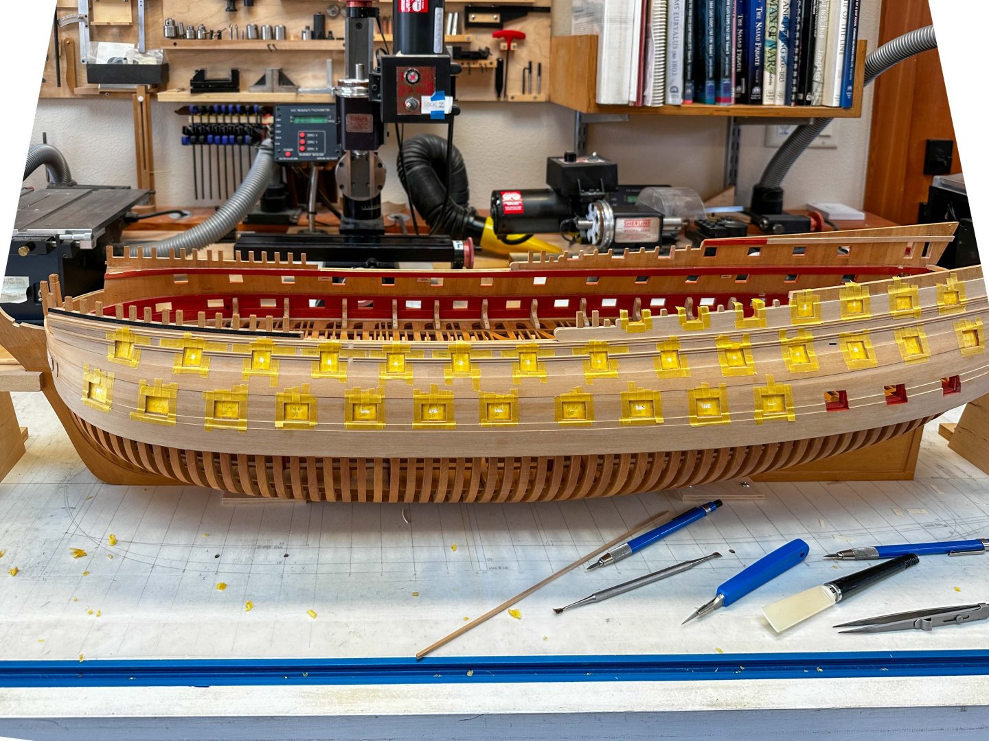
-
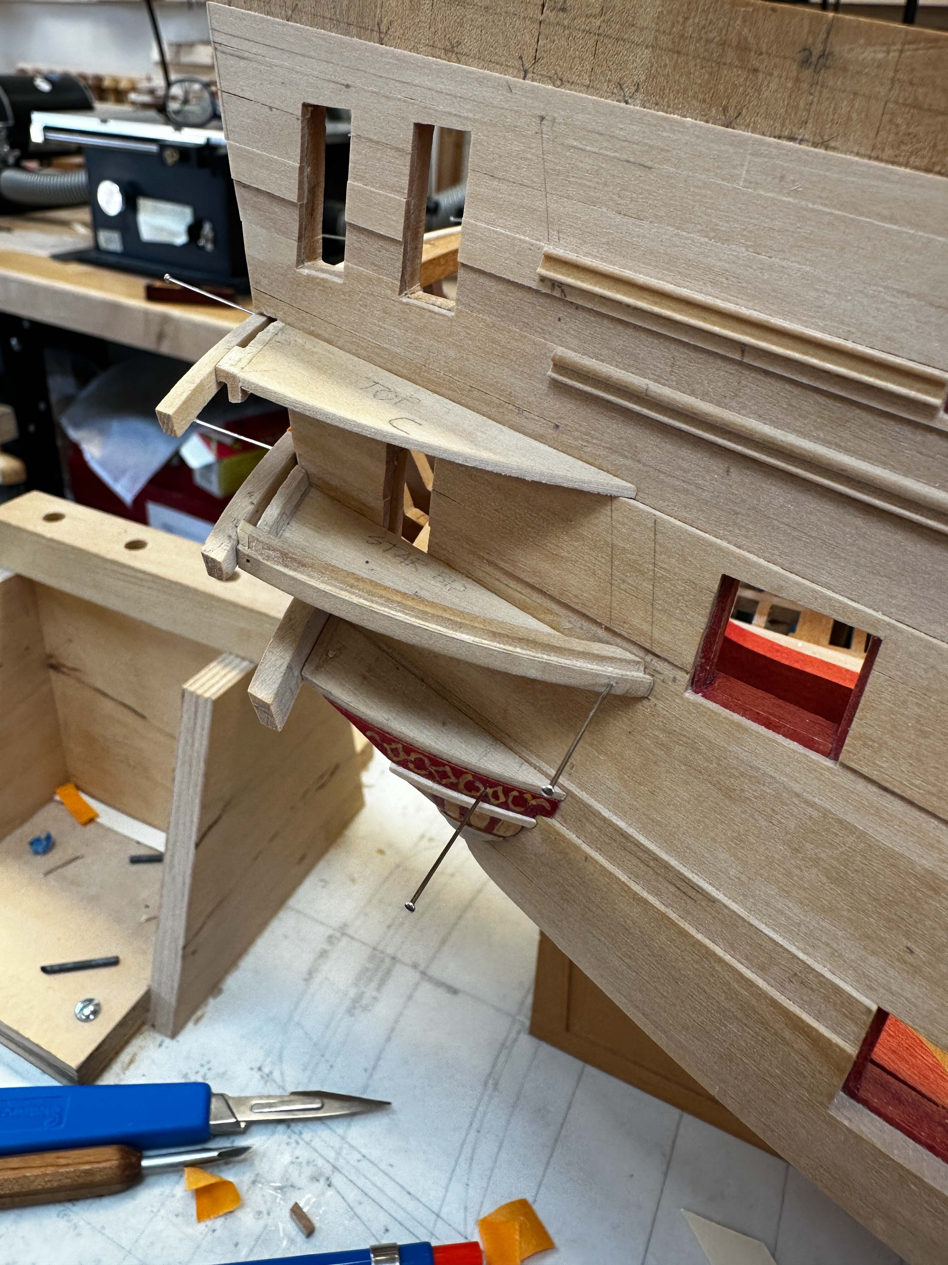
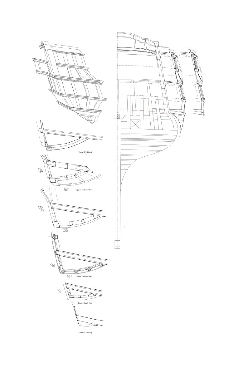
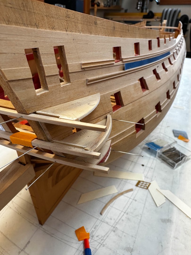
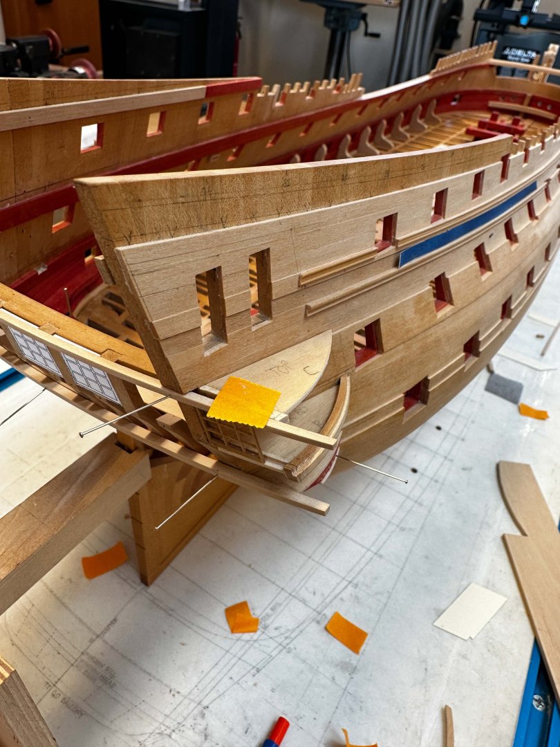
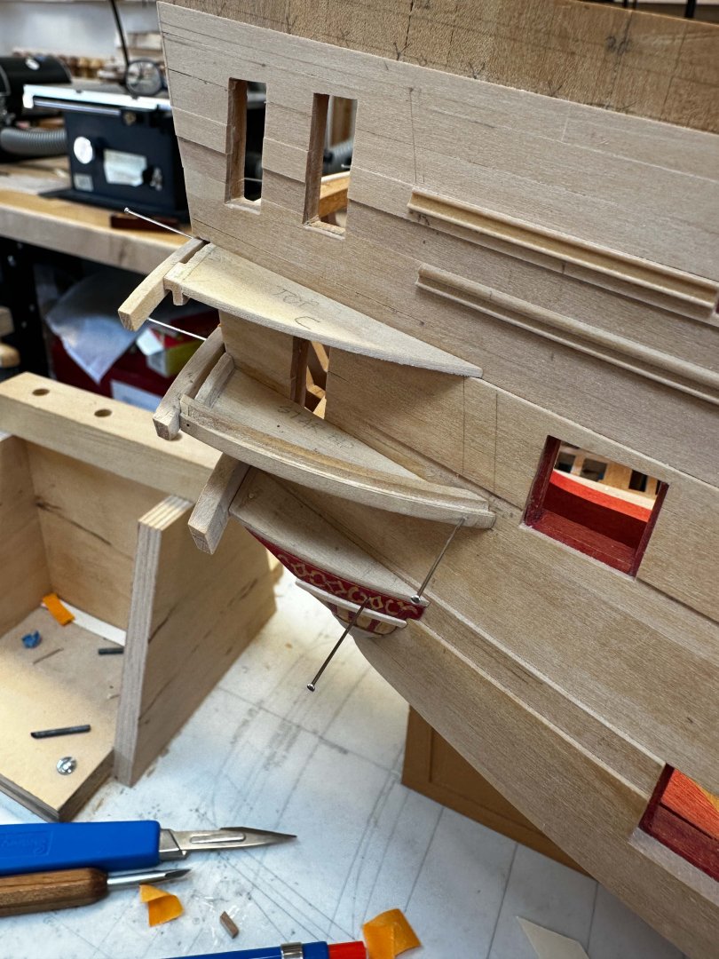
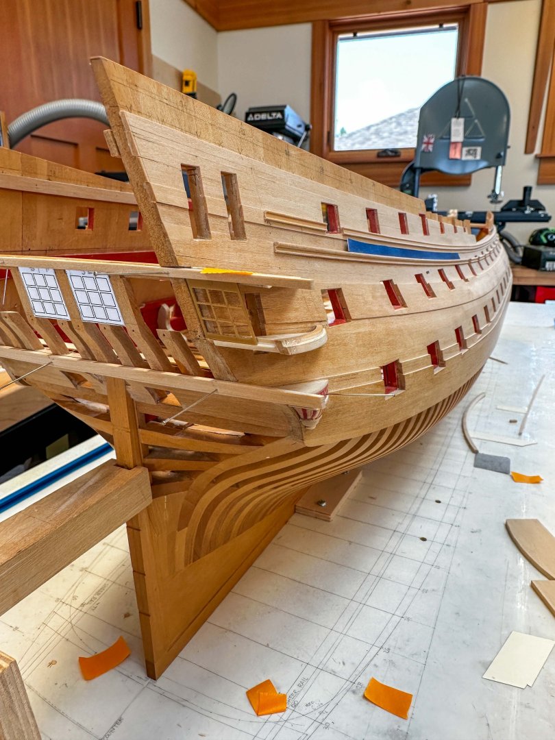
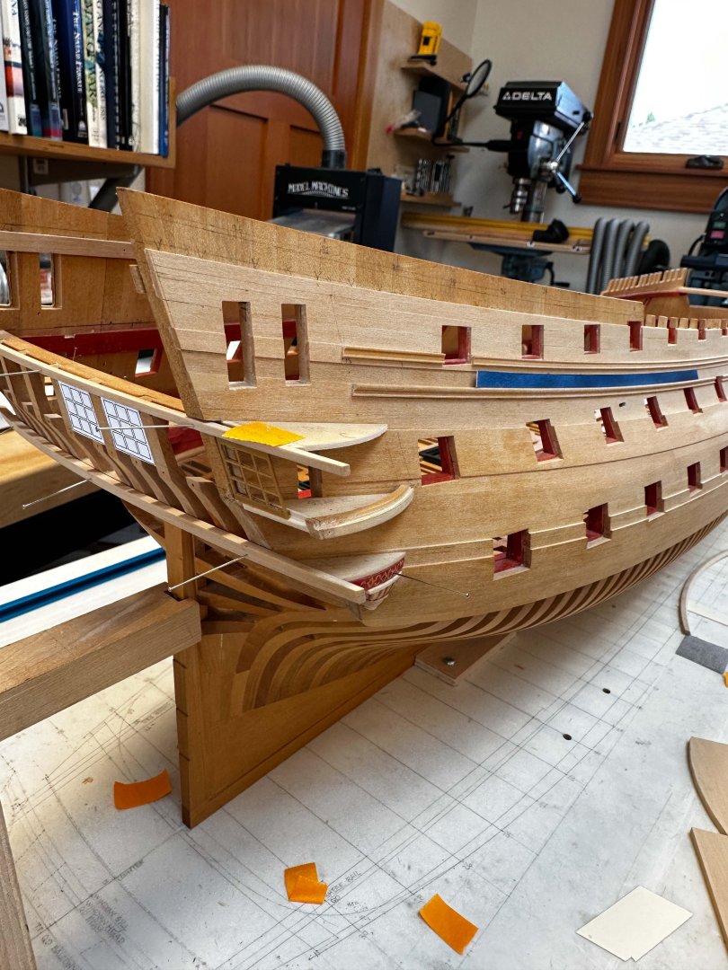
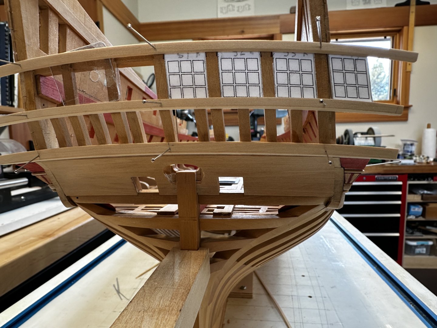
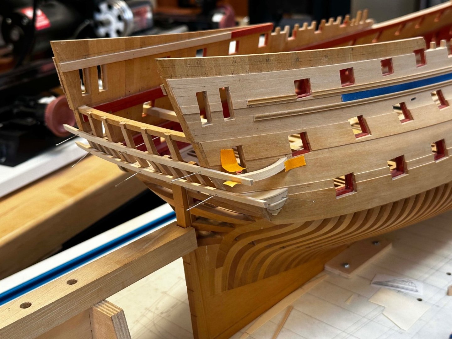
Sorry for the long delays in posting. Lots going on in the summer outside the shop, and progress is very slow when I am in the shop! Thanks so much, druxey, Albert, Marc and Michael for your kind thoughts. These keep my spirits up as I plod through the slow business of building the quarter galleries. I have found it most effective to treat each level of the quarter galleries--at levels of both decks and railings--as a little platform with the structural rails temporarily glued to the outside edges. This allows me to keep the correct curve and location where the rail hits the side of the hull. I used the mouldings at the stern as guides for the angle at which the platforms are temporarily glued in their locations, and carefully measure from the channel wale to find the correct sheer fore and aft. I check with a height gauge to ensure the platforms are symmetrical port and starboard. I recalled reading many years ago that the fore and aft curves of the quarter galleries must be parallel to each other, although offset fore and aft by the amount of the slope of the aft windows. This is to ensure that the vertical mullions are parallel to each other and not in different planes which would create a twist in the plane of the windows themselves. Not good for flat sheets of glass! So I was very careful in maintaining the angle at the aft, outboard, intersection of the two structural rails. This ensures that the platforms above and below the window will remain parallel to each other even as the sides of the hull at different heights vary in their angles due to the tumblehome. This should become clearer in later posts, when I start to lay out the mullions themselves. Here are more images of the platforms slowly coming together. The first one below also shows how the structural beam at level C had to be notched for the window frame to slide up behind the stern moulding. It is actually a blind window, but I needed to do this so my windows would remain constant in their heights across the full width, for ease of construction. Best wishes, Mark

-
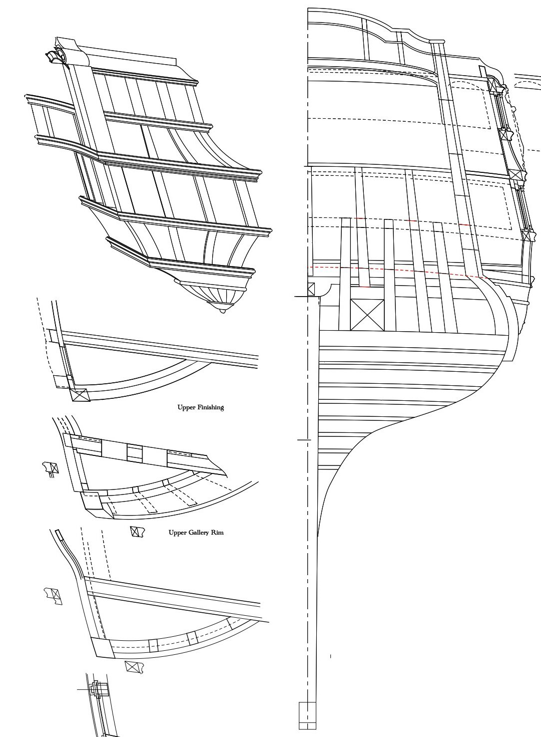
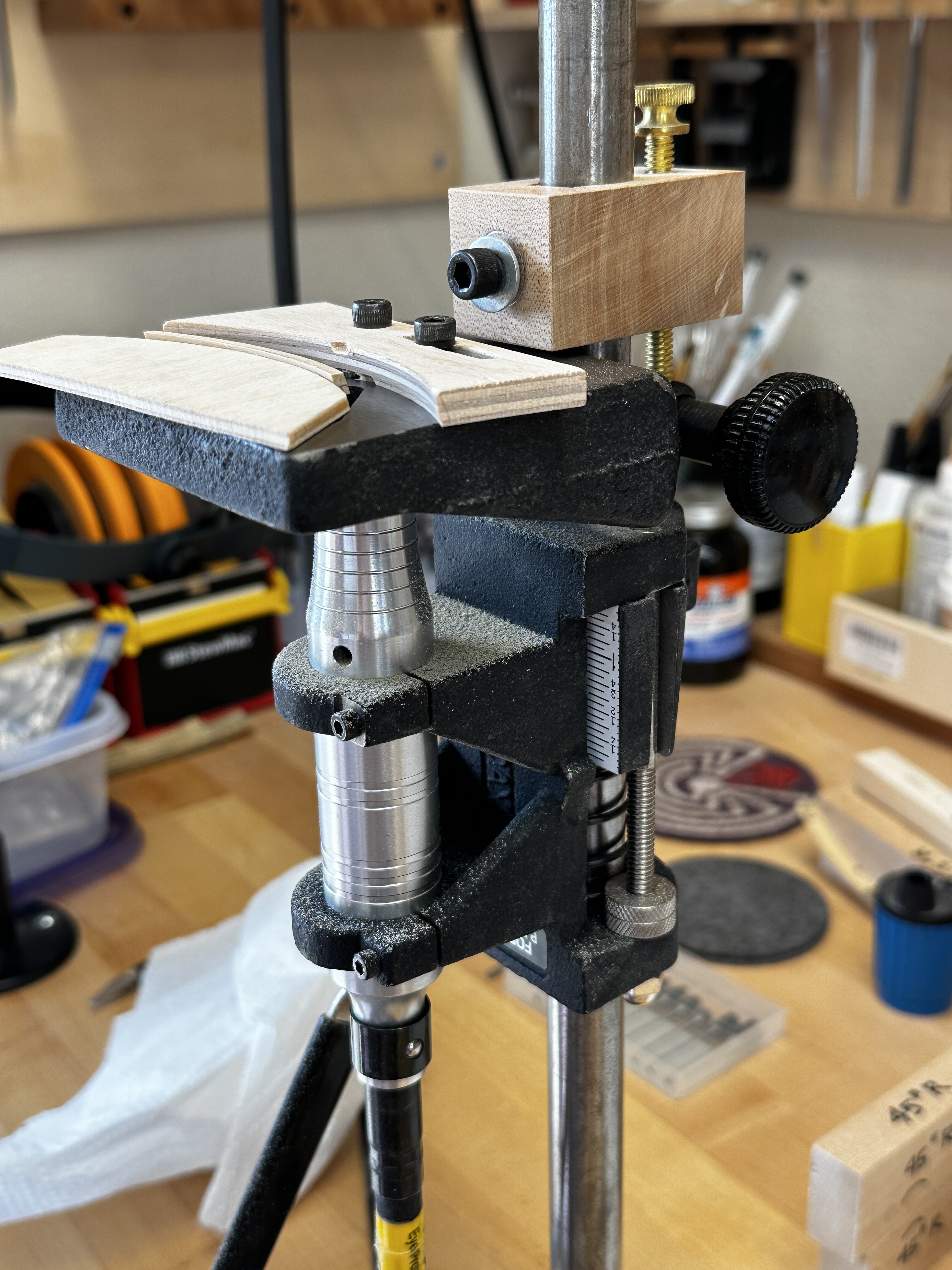
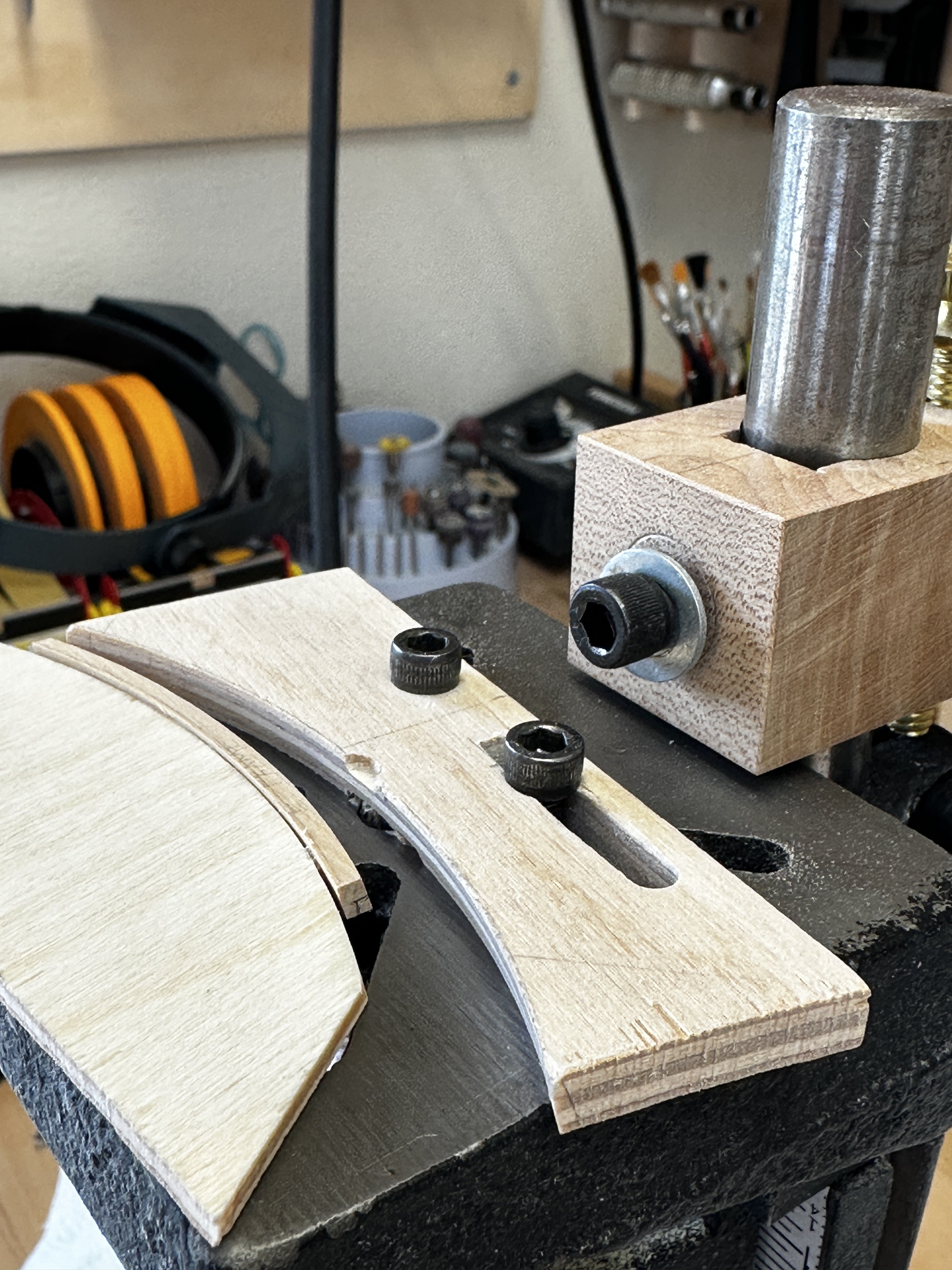
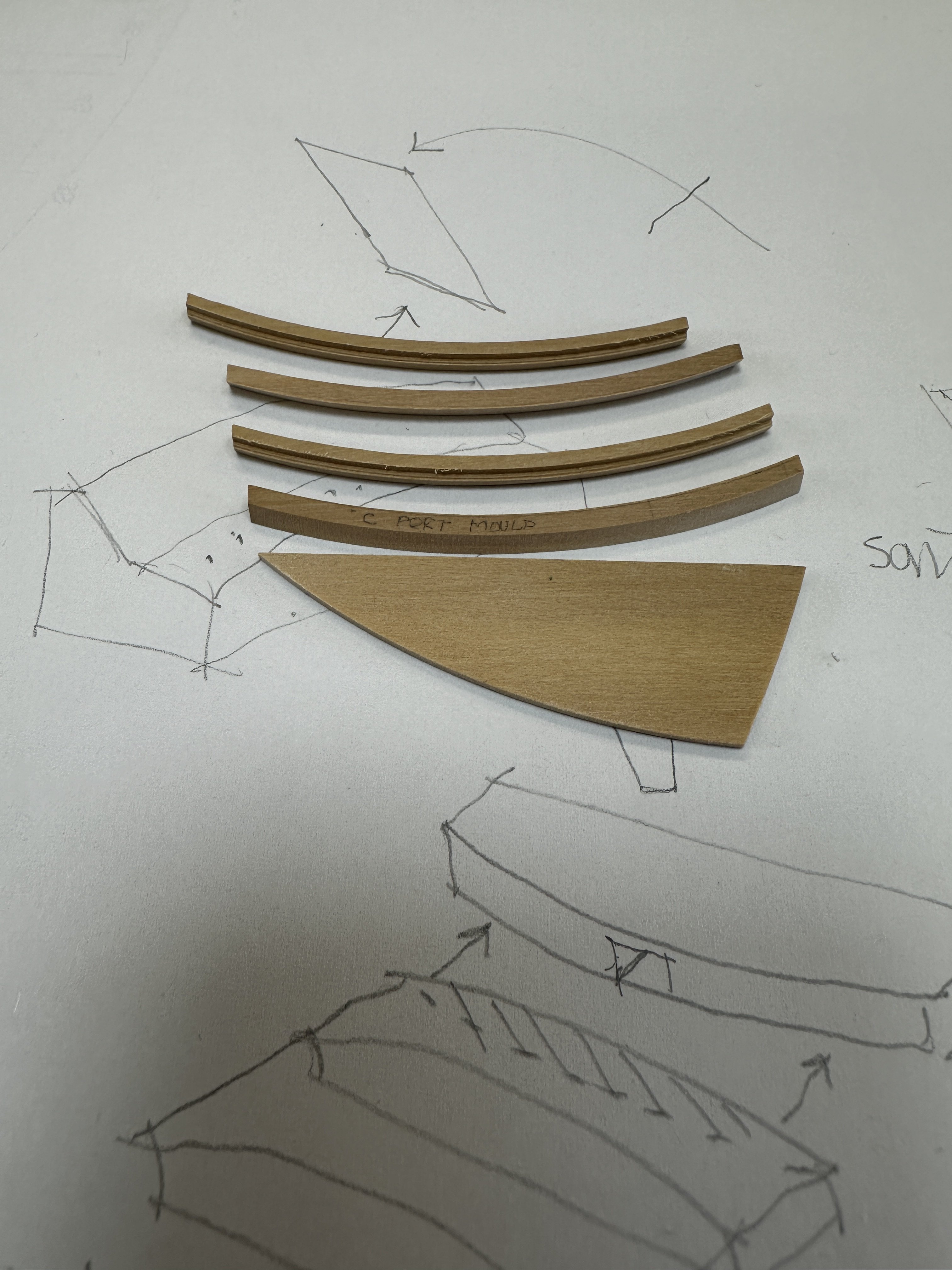
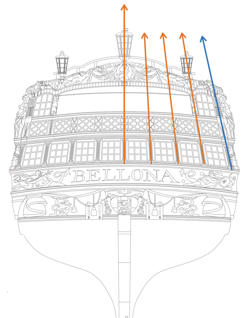
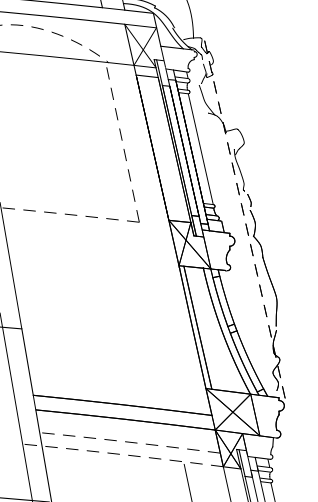
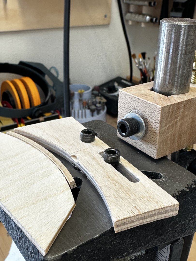
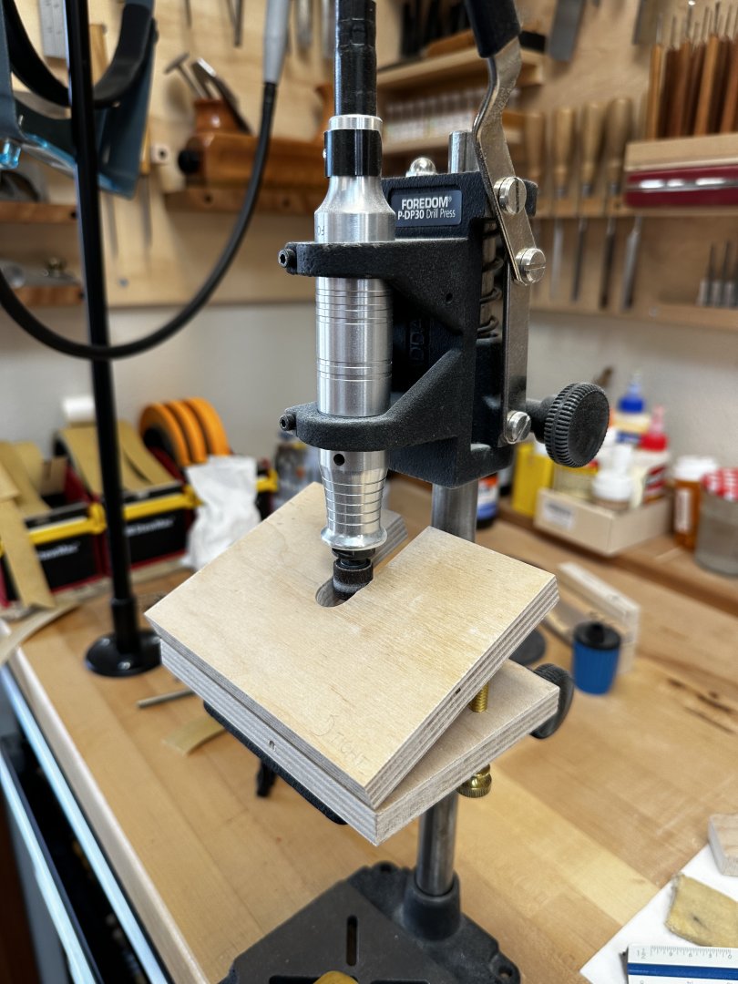
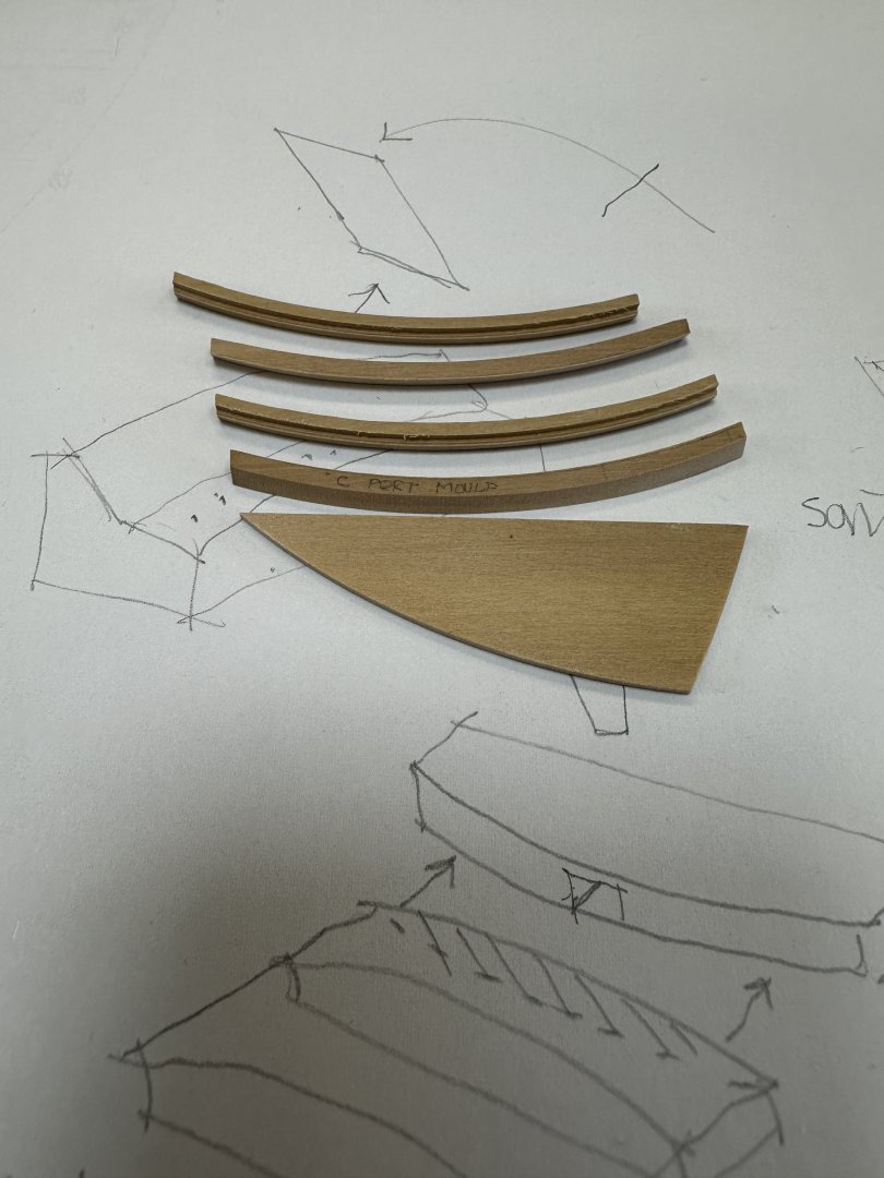
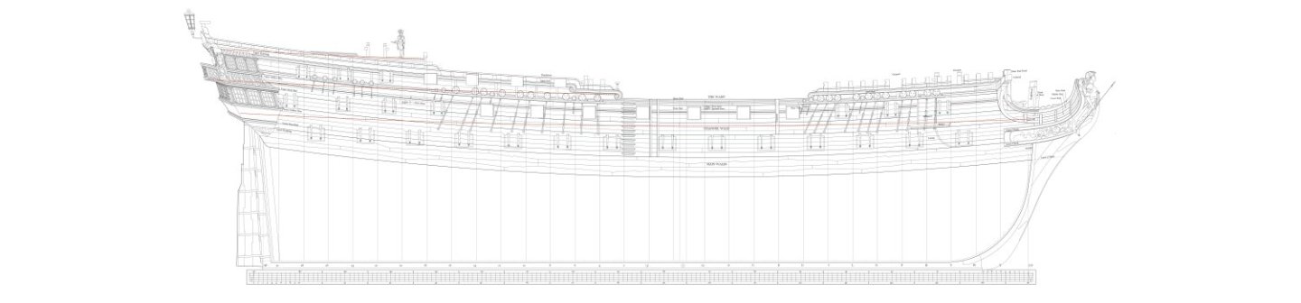
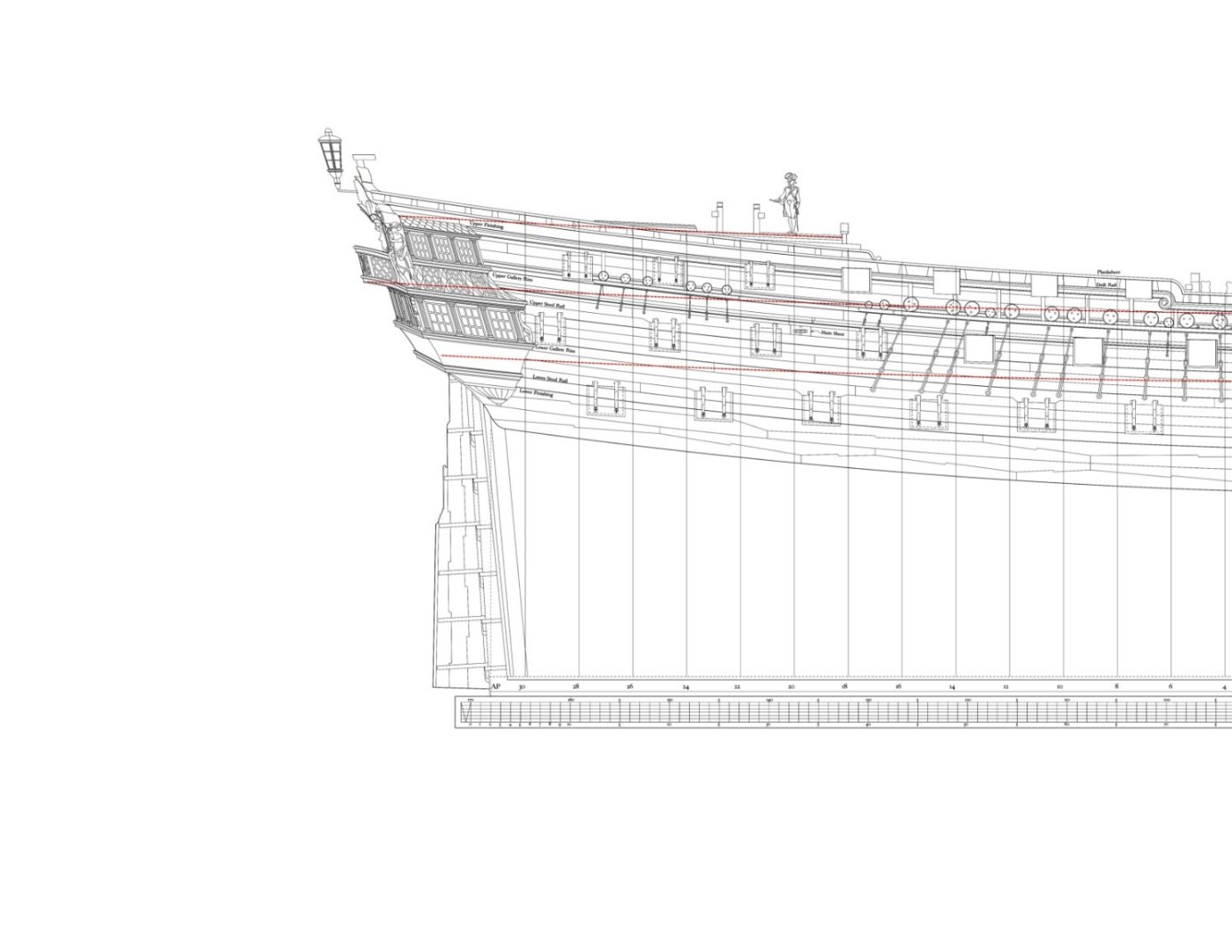
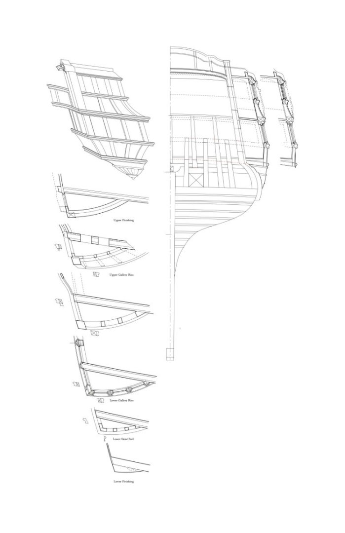
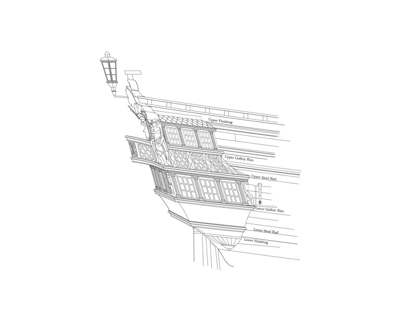
Hi Dan and druxey, Your recent kind comments made me realize that I have not posted in a long time, and you inspired me to catch up a little. I am still a little slow after my health issues, although things are definitely on the mend. What has slowed me the most is that this stern is exceedingly complicated to construct, I have discovered. I have had to do more drawings to figure out how everyone will go together, and then fabricate a number of structural members that will eventually form the framing for the quarter galleries. This has involved cutting parts with a roundup like the decks, with a curve fore and aft, some with a slope matching the aft face of the quarter gallery and some others with a slope matching the outboard face of the quarter gallery, and then rabbets on these multi-curving surfaces for windows top and bottom. I have made many mistakes so far, keeping it all straight.... First, determining the location and widths of the quarter galleries relative to the hull. There are no original drawings of the Bellona stern, and only the most basic hint of the quarter gallery plan, showing the curvature of its outboard edge. So I had to reconstruct from photos of the models, and some geometry. The key to reconstruction is that the stern windows to the upper deck are evenly spaced, and they all converge at a point some distance above the hull. In the drawing below, the 4th orange line to the right is the end of the hull itself, while the blue line is the outer edge of the quarter gallery window. Keeping the spacing of the windows the same, and on the correct angle, this then tells me the width of the quarter gallery at various levels: Here are windows mocked up to determine the lengths of the stern mouldings forming the various levels of the stern:' The following drawing shows some of the geometry involved in the structural parts. Nothing is true size in these, since they are bending and sloping. Everything will have to be measured on the hull itself, and parts fitted to previous parts. Then I had to determine how to make the windows, and therefore how to frame for them. I mentioned before that Chuck has laser cut some beautiful prototypes for me, using my drawings. I have decided on .029" plastic, painted to match the boxwood of the hull. Using mica for the glass (.005" thick) means that I can build windows thin enough to bend to fit their curving surfaces. But to do that, I had to devise a way to trap the window frames and mica between the outer moulding and a rabbet in the structural frame behind. You can see below how the structural frame behind the windows has a rabbet, and once the mica and window frame are put in, the moulding then presses the two tightly together. That is the plan, anyway! You can see in the drawing below how the structural frame (with the crossed lines) slants inward, and also of course bends from the outer edge of the quarter gallery at the stern, to hitting the hull further forward. The frames on the aft side of the quarter galleries also have to round up like the decks. To make these curved and sloped parts, I made an adjustable angle table for my Foredom. I pre-cut each curve with a jeweler's saw, then sanded to the line making a sloped, curved, edge. I then refined these edges on an appropriately curved sanding stick. I then set up a fence on the Foredom with the handle and bit turned upside down, to act as a router table with the bit coming up from underneath. Below you can see the rabbet marked on the end of the structural piece (temporarily glued to the edge of a plywood handle, to keep my fingers away from the bit). The tops of the windows required an acute angle--made with a dovetail bit as below-- and the bottoms required an obtuse angle made with a straight bit. And here is one set of frames (port and starboard) and moulding blanks for the sides of one level of the quarter gallery. All of the sides are now complete. I am now working on the structural frames on the aft end of the quarter galleries. Maybe someday I will be able to start putting some of this together! Best wishes, Mark


-
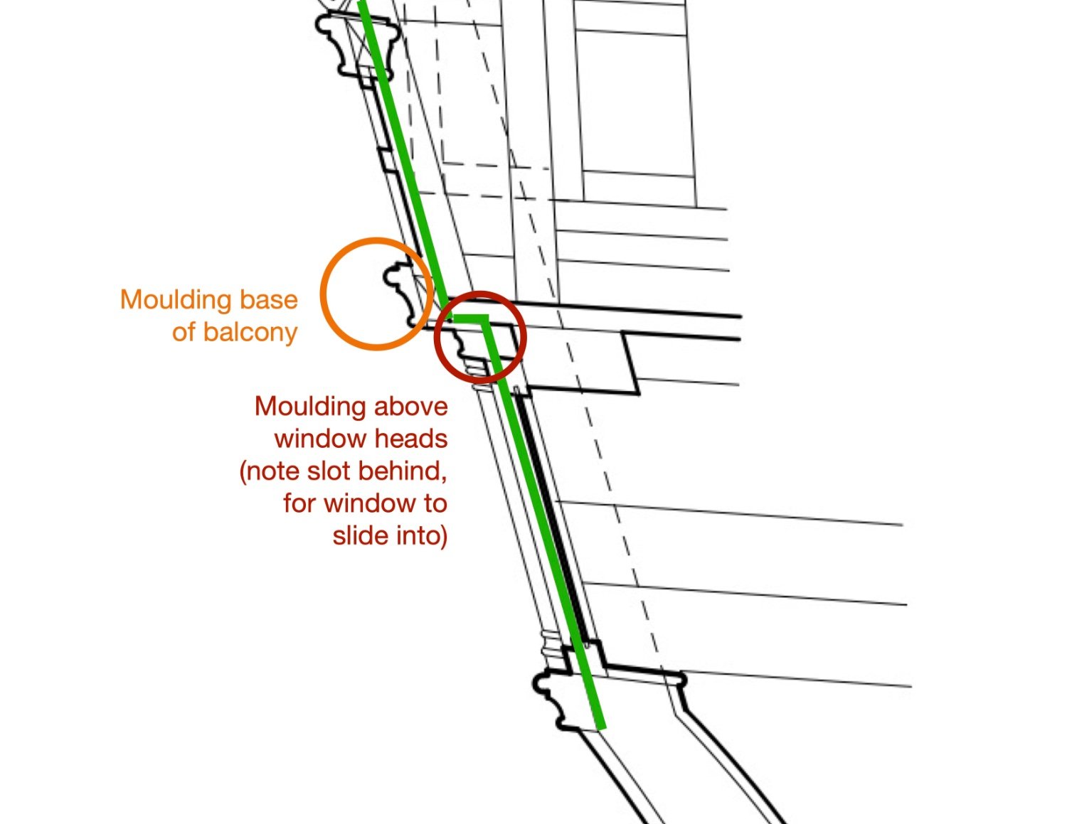
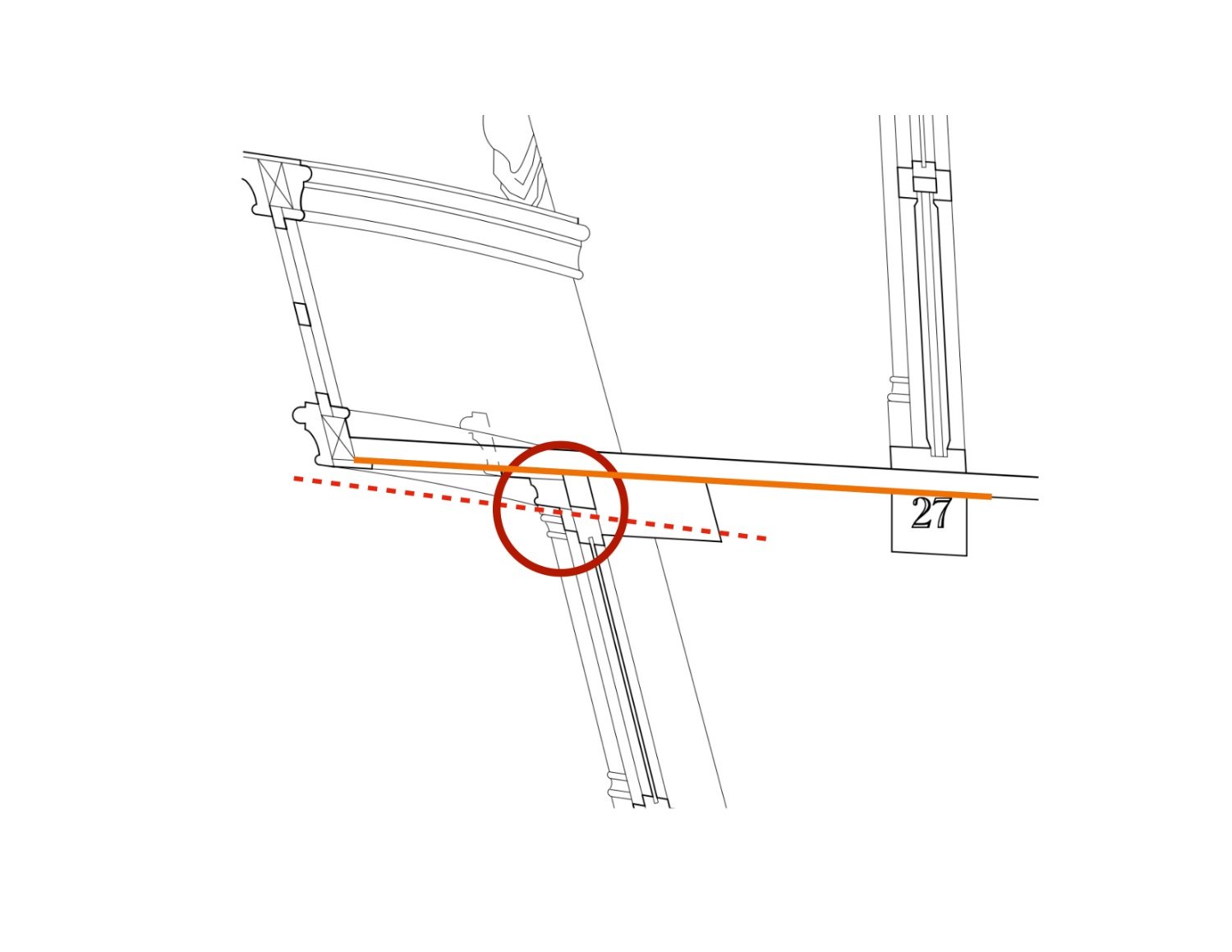
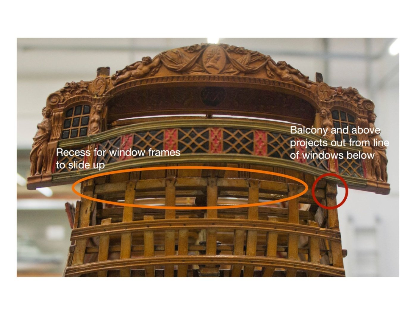
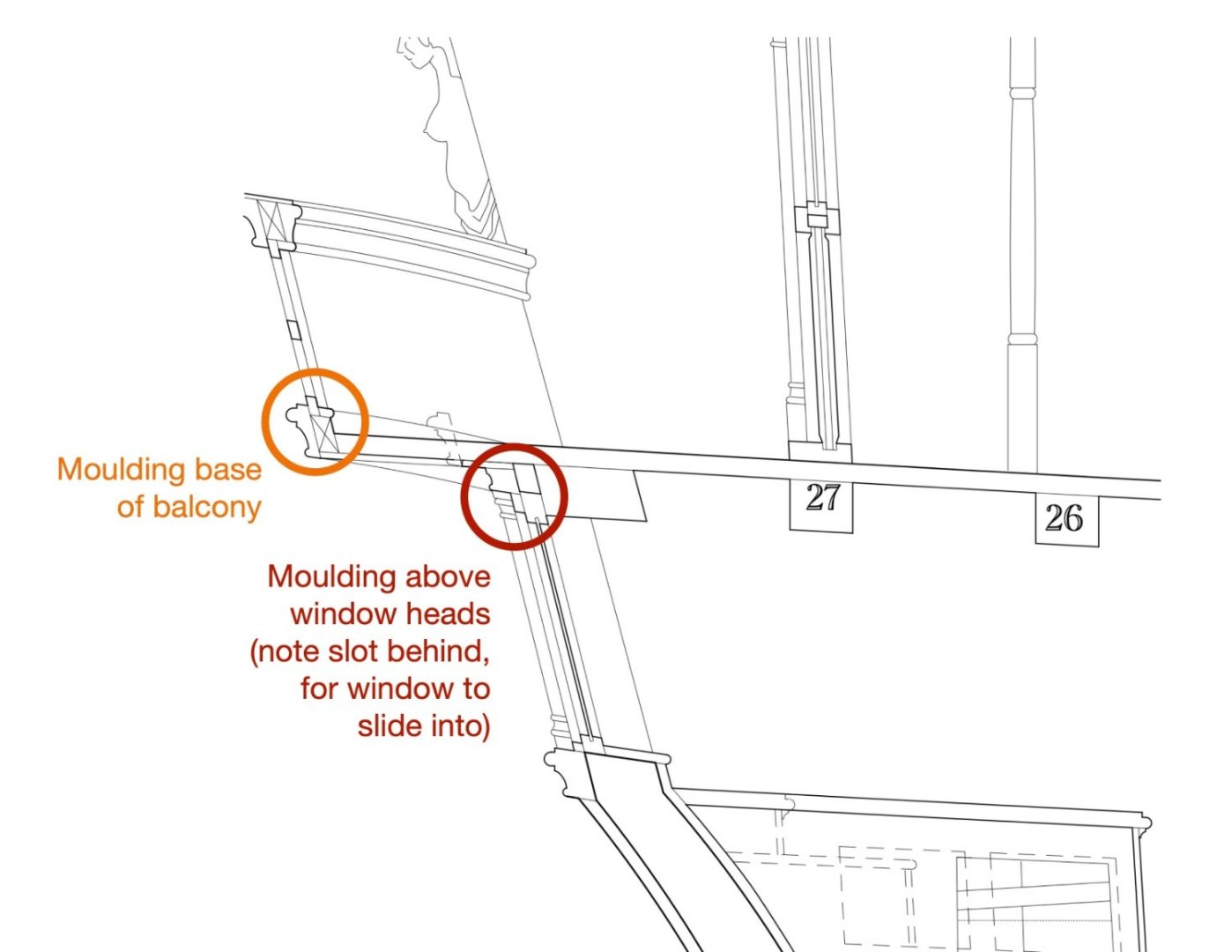
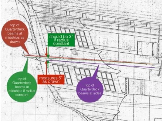
Now for some analysis of geometry and construction. Fifteen years ago, I built the stern frame based on my observation of the first Bellona model, and the Admiralty drawings. I did not understand what I was building at the time, I just followed what I saw. And now I understand as I get into the details. In the model, you can see a couple of strange things. first, the tops of counter timbers with the dovetail joints stand proud of the horizontal transom tying them together. This leaves a gap of about 2". I now realize that these gaps provide a space for the bank of sash windows to slide up into. It means that the windows can be opened at the bottom by about 9"; not a lot, but better than no opening! Second, the side counter timbers, effectively the end of the hull frame, project out from the bottom of the balcony upwards. that is, the bank of windows are recessed back relative to the balcony, creating a shadow line between the upper and lower parts of the stern. There is no functional reason I can see here; it is a visual trick to emphasize the sweeping serpentine curve of the balcony from one side of the composition to the other. That creates some complication in how this is constructed. The green line shows the aft most edge of the side counter timbers, or hull. There is one moulding along the tops of the window bank, just under the balcony, in red below. Another moulding runs along the base of the balcony, in orange below. when the balcony swings out from the stern, the two mouldings split from each other: The next item I did not fully appreciate until I started constructing the stern is how its design needs to reconcile two geometries working against each other; the upper sweep of the sheer, and the flatter sweep up of the decks (red lines below). The conflict shows a little where the gun ports cut into the sheer in odd places. But at the stern they really need to be resolved. One of the most important, I discovered, is that the moulding at the tops of the windows must align with the sheer of the deck at its upper edge (orange line below), since it sits flush under the deck itself; but its lower edge must conform to the sheer of the hull (dotted red line below), since it turns the corner and runs along the side of the quarter galleries that align with the hull's sheer. And then one more thing about the stern. In 2014, ten years ago, I posted a question about the stern geometry (posting #173). I noticed a discrepancy in the drawings relative to the roundup of the quarterdeck. If I continued the deck aft with its normal roundup, it was a couple of inches lower than the deck as it was shown coming out into the balcony. There was a lot of discussion around posting 173 as to whether this was a mistake in the drawing, or something else. I finally found in Steel that the quarterdeck does indeed increase its roundup as it approaches the stern balcony, to give a lighter, more springy feeling to the visual lines of the stern. So the drawing is correct, and this needs to be accounted for: So, construction next! Mark


-
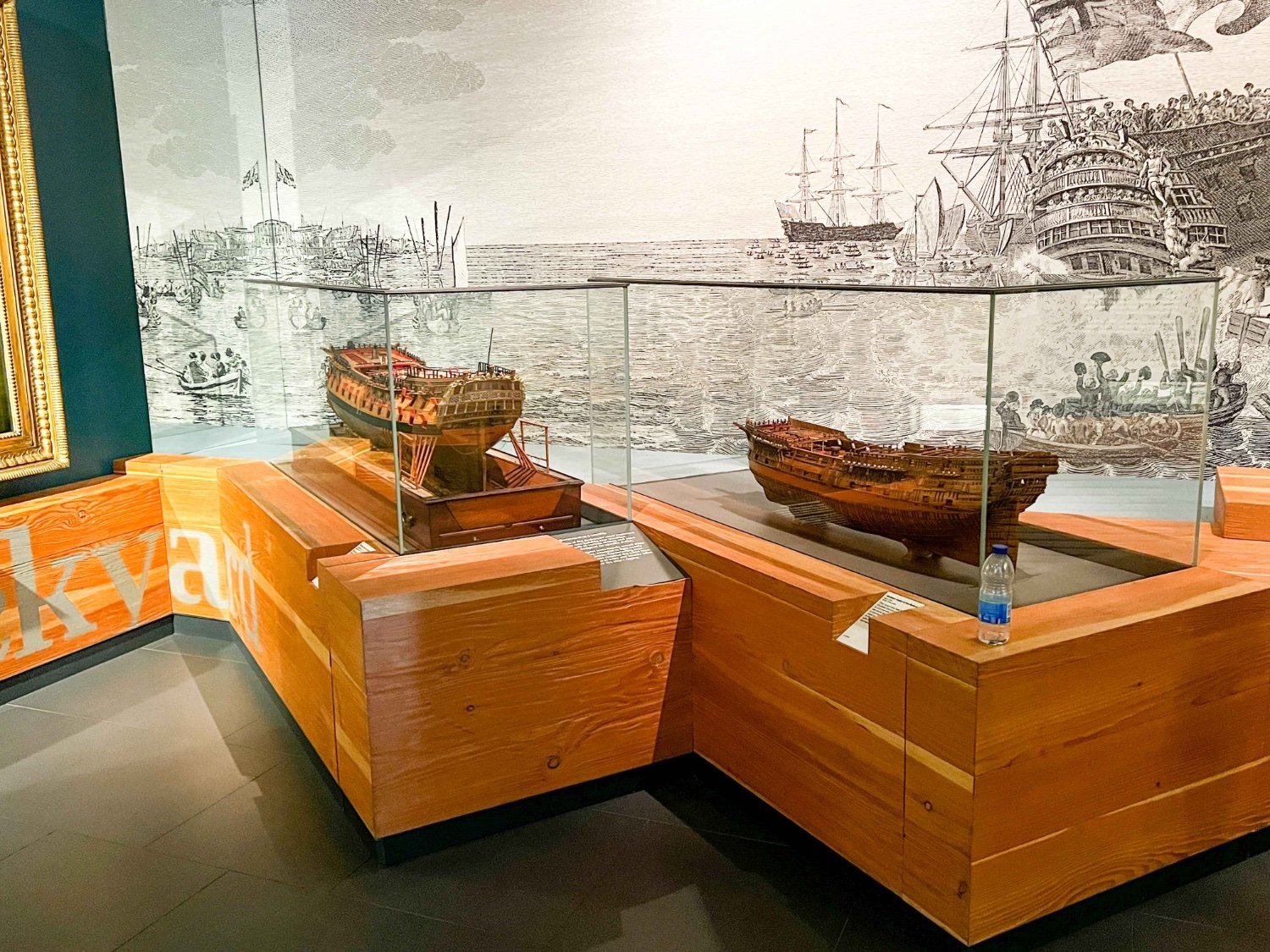
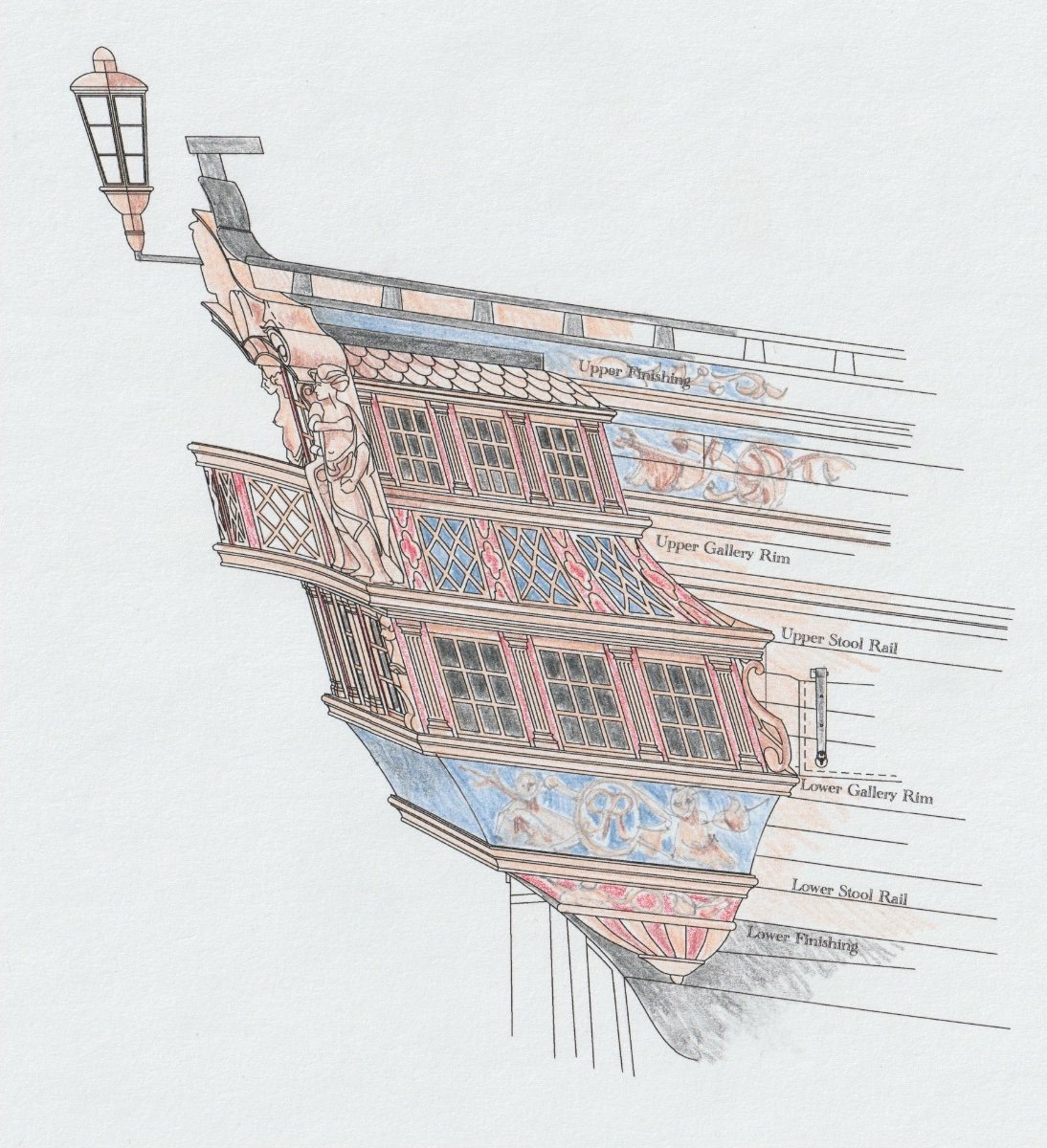
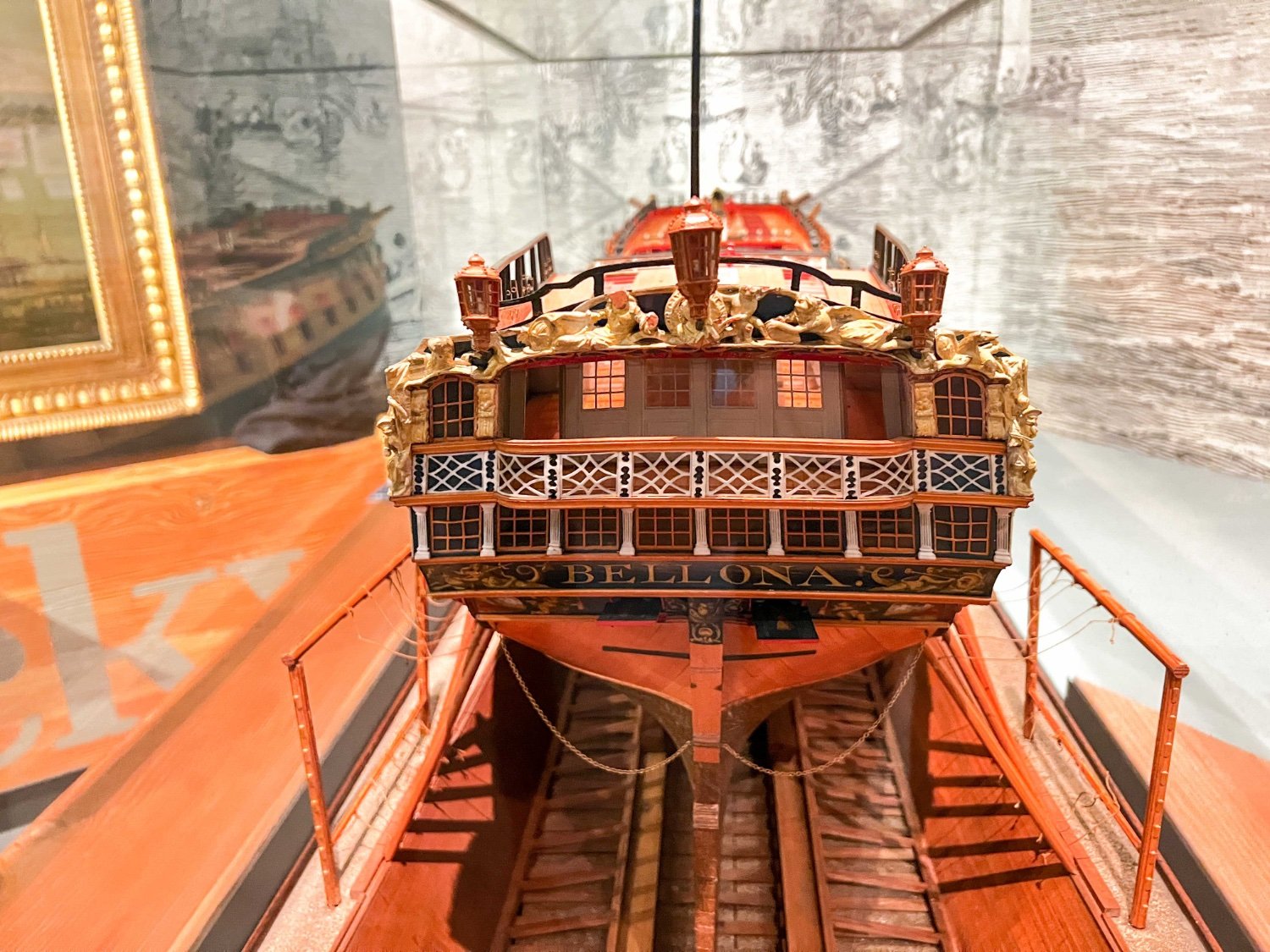
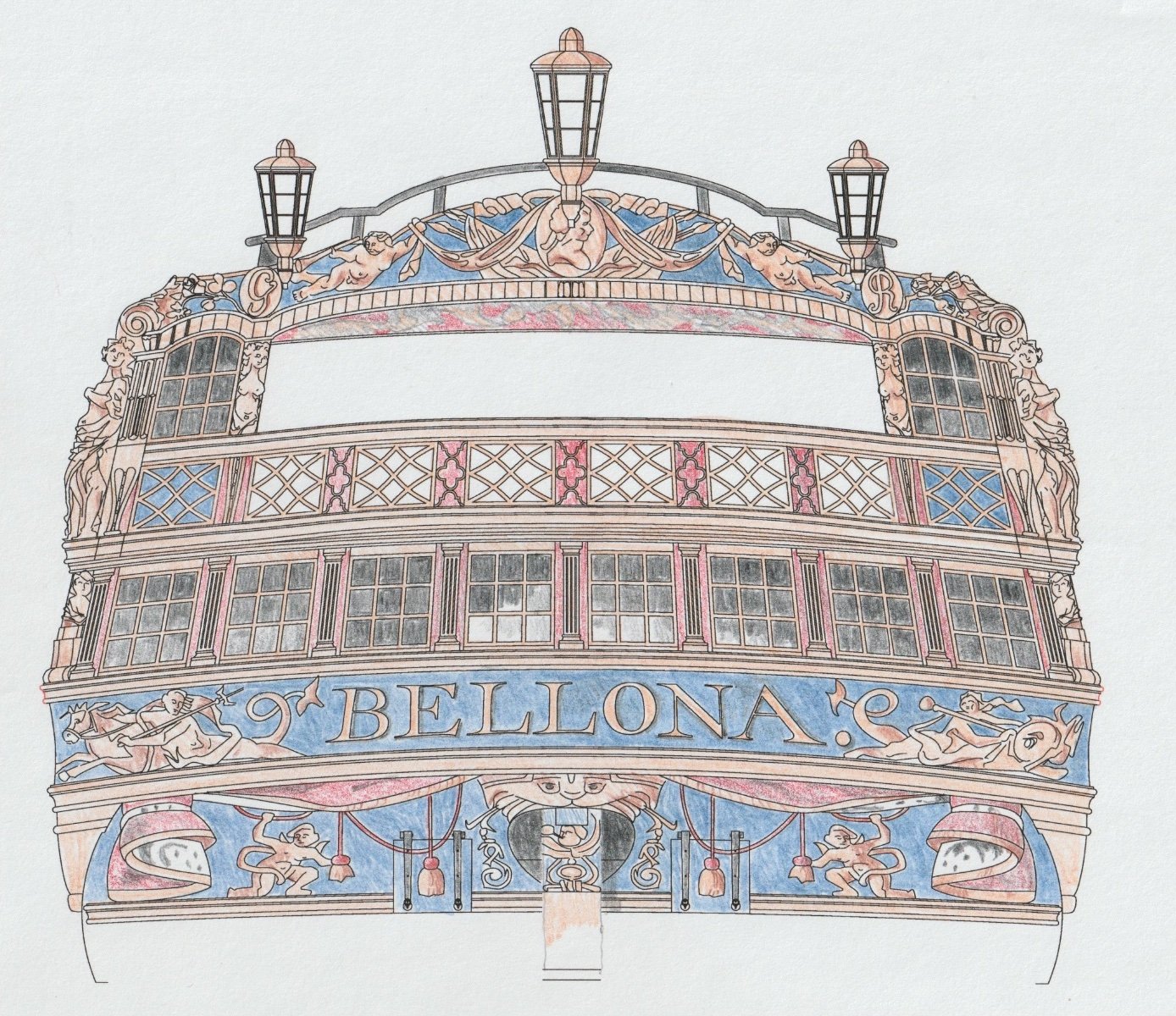
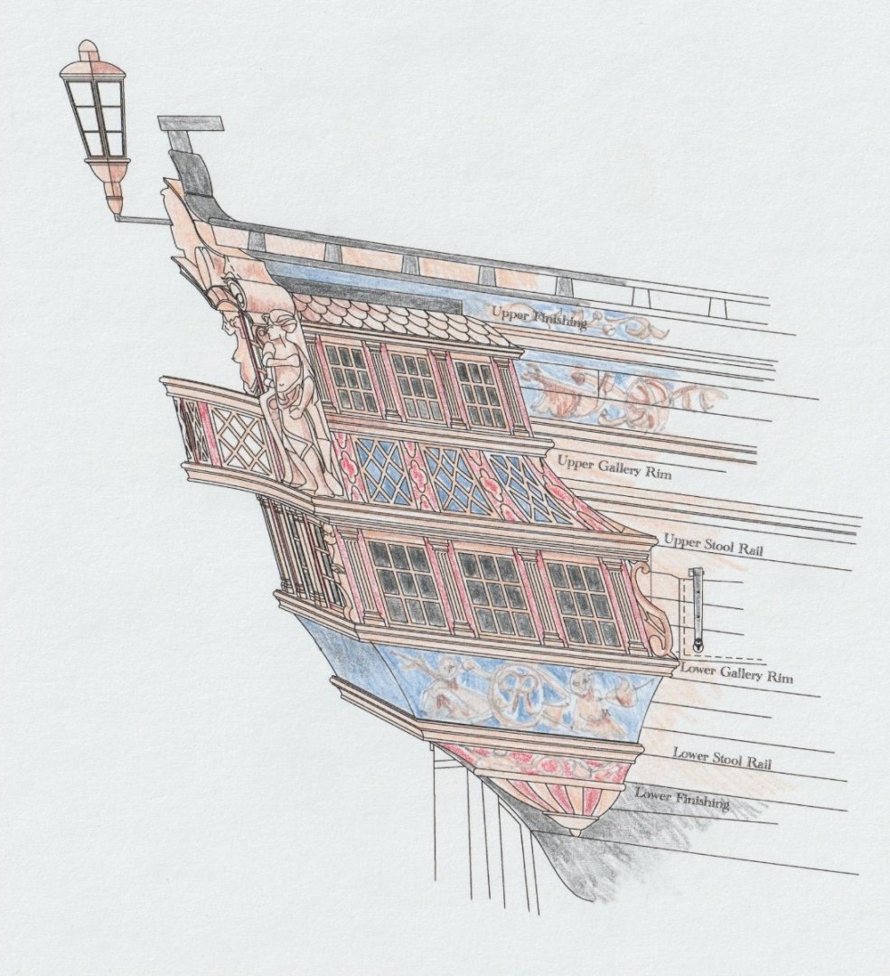
Yves, thanks for sharing your model. I was aware of a kit, but I have never seen it! It looks like you did a very nice job of it. scrubbyj, the history of the Bellona in Brian Lavery's Anatomy of a Ship has the ship paid off in 1762 after her initial service, turned into a guardship, briefly recommissioned, and laid up in ordinary in 1771. Then she was given a major repair in 1778, completed in 1780. this was now 20 years after her original launch. I can only assume that the first model represents her before the major repair, and the second one represents her afterwards. Adding that railing on the roundhouse bulwarks was very typical of designs of this later period, as best I can tell. Visiting my son in London last year, we visited the National Maritime Museum and toured around endlessly disappointed that they had removed most of the models. Then we walked into the room devoted to the Napoleonic Wars, and there were two representative models, the first and second Bellona models side by side! At last two decent models, and they were the Bellona! In this photo you can see that the second model is larger than the first, which I never realized until seeing them side by side. Busy day outside the shop, not as much done on the Bellona as I had wished... But I did get a chance to color the stern quarter galleries based on my reconstruction:

-
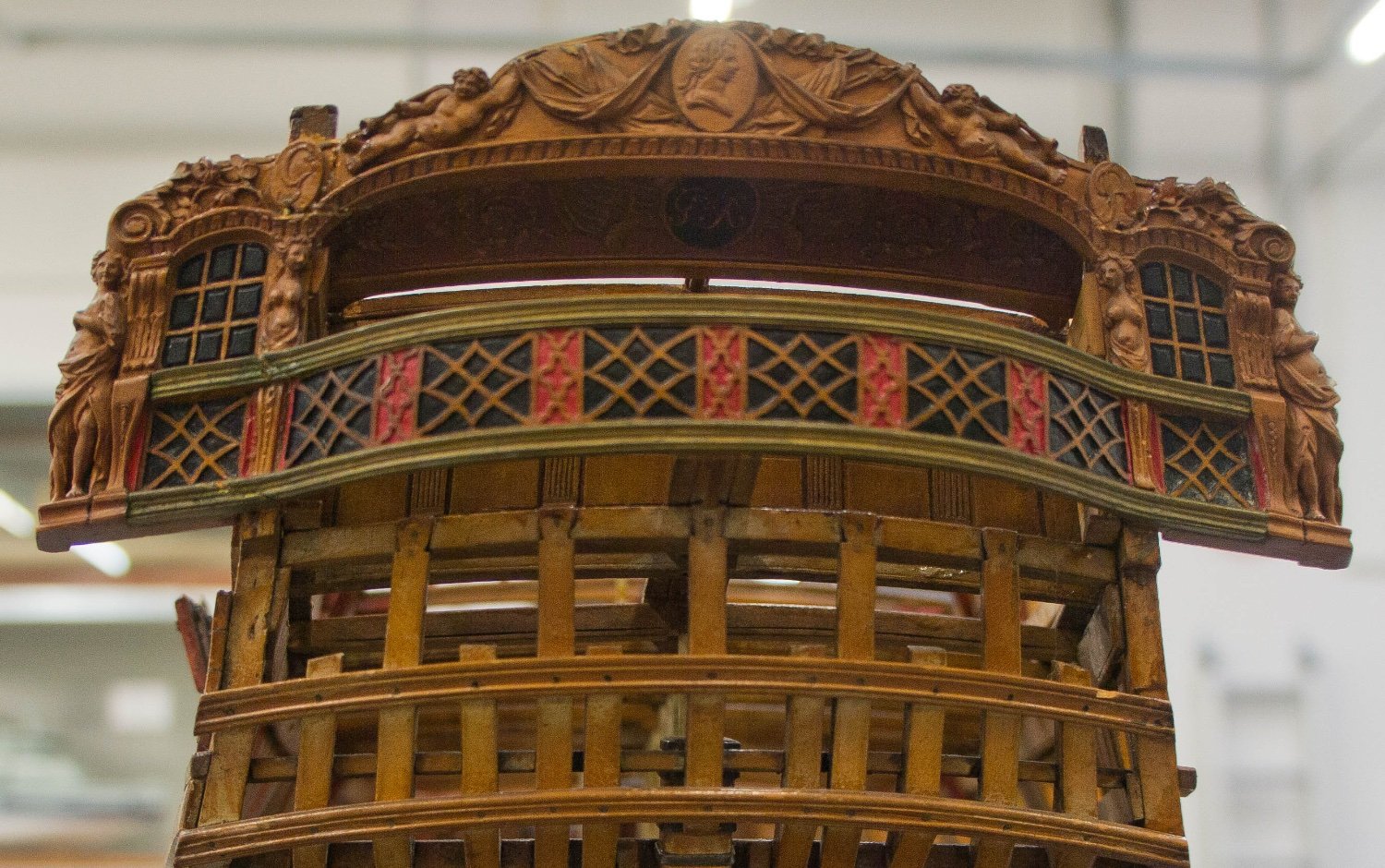
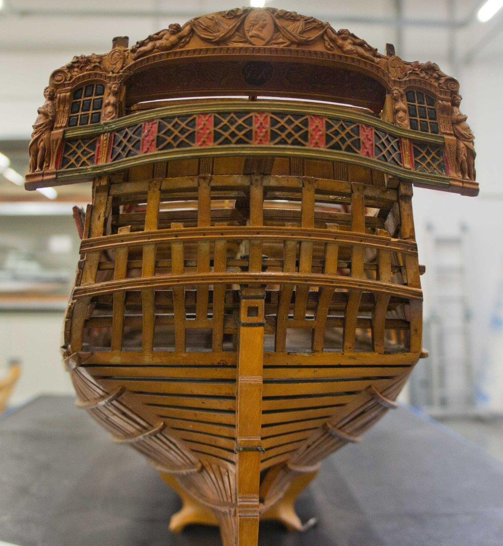
Thanks so much, Marc, Hakan, Allan, Mark and Dan. It really means a great deal to me to hear from all of you. I have a meeting with a pain specialist on Friday, and hopefully I will be able to get past this soon! In the meantime, I have been working away on what has been the biggest challenge for me so far, the stern. I plan to make a number of posts on this, starting today with an overview of the end goal; what will it look like? I have always aimed to base my model on the original design and the first model, shown here: Although this model shows mainly the framing system, it does have a hint of what the original design intended on the stern at least down to the bottom of the captain's balcony. Everything past this is speculation for a reconstruction! The second model, made twenty years later after a major refit of the ship itself, shows much more detail (see below). At first glance, this provides information on all of the detail not shown in the first model. But the second model changed the original design in ways I did not find pleasing. It added an ugly railing above the roundhouse (nice for the sailors, bad for the aesthetics). The balcony railing makes a sharp turn into the stern one bay inboard on each side, whereas the original model has a nice sweeping serpentine curve across the entire stern. The original model has nicely proportioned vertical supports (painted red) with nicely detailed fretwork, whereas the second model skinnies those down and punches crude holes for detail. The first model carries additional carving down to the bottom of the railing adjacent to the large corner post carvings of women, linking things together visually. The second model unsatisfyingly smashes the balcony into the corner sculpture. And in terms of color, the second model uses white for the balcony fretwork and the pilasters on the band of windows, which I find visually jarring relative to the rest of the ship. There are a few other examples of white windows, pilasters and fretwork on other roughly contemporary ships, most notably the Princess Royal in the Annapolis museum; but not many either in models or paintings of the period. This is not typical, in other words. I suspect this was the modeler's effort to give visual "punch" to his model, not a reflection of common practice in the actual ships. I suspect the Princess Royal model has white details like the Bellona second model because it was built by the same modeler; the friezes on both ships are identical in painting style and technique, and the models were likely built at the same time. It may be two different modelers used the same frieze painter, but given the rarity of this look in most other ships, I think we are seeing the personal signature of a modeler here. I would be very interested to hear if others have another view of this. So, how can I reconstruct the original model, from the incomplete information in the original model? Here, for better or worse, is my first shot at a reconstruction (see below). I reproduced the balcony geometry, the carvings, and the wider balcony vertical supports with the more elaborate fretwork. I picked up the little bust carvings below the balcony from another contemporary ship. I accepted the pilaster design from the second Bellona model, although in the spirit of visual harmony I continued the red down from the balcony into the boards behind the pilasters. In the same spirit of visual harmony, I propose to keep the pilasters and the window frames natural wood, along with the carvings and mouldings. The second model friezes and paintwork on the upper and lower counters are really quite delightful (just like on the Princess Royal). So why not use them, with no other sources to draw upon for this? I propose to reproduce those paintings in my model, including the tone and hue of the background blue paint. I would be very interested to hear any opinions as to whether I am on the right track on this reconstruction. Next posting will discuss the very complex geometry in this stern, and my efforts to bring it under control for construction. While I am working on that, I am also working with Chuck of Syren models, who is going to laser cut the window frames and balcony fretwork for me, using my drawing templates. I had long wanted to make everything on this model myself, but I finally had to face the reality that I did not have the skill to make window frames just .023" thick, or even worse, the pierced fretwork. And after a long and fascinating chat with Chuck at the Admiralty Models workshop on carving in Annapolis in October, I came to see that this is just using another tool to achieve my modeling needs, still based on my drawing. Thank you Chuck! By the way, Chuck also pointed out to me that the very fine details like window frames were made of ivory in original models, because it could hold the detail better than even boxwood. Most models seem to have colored this; the second Bellona model builder maybe put up the freshly cut window or fretwork and thought, "looks good as is!" Best wishes, Mark


-
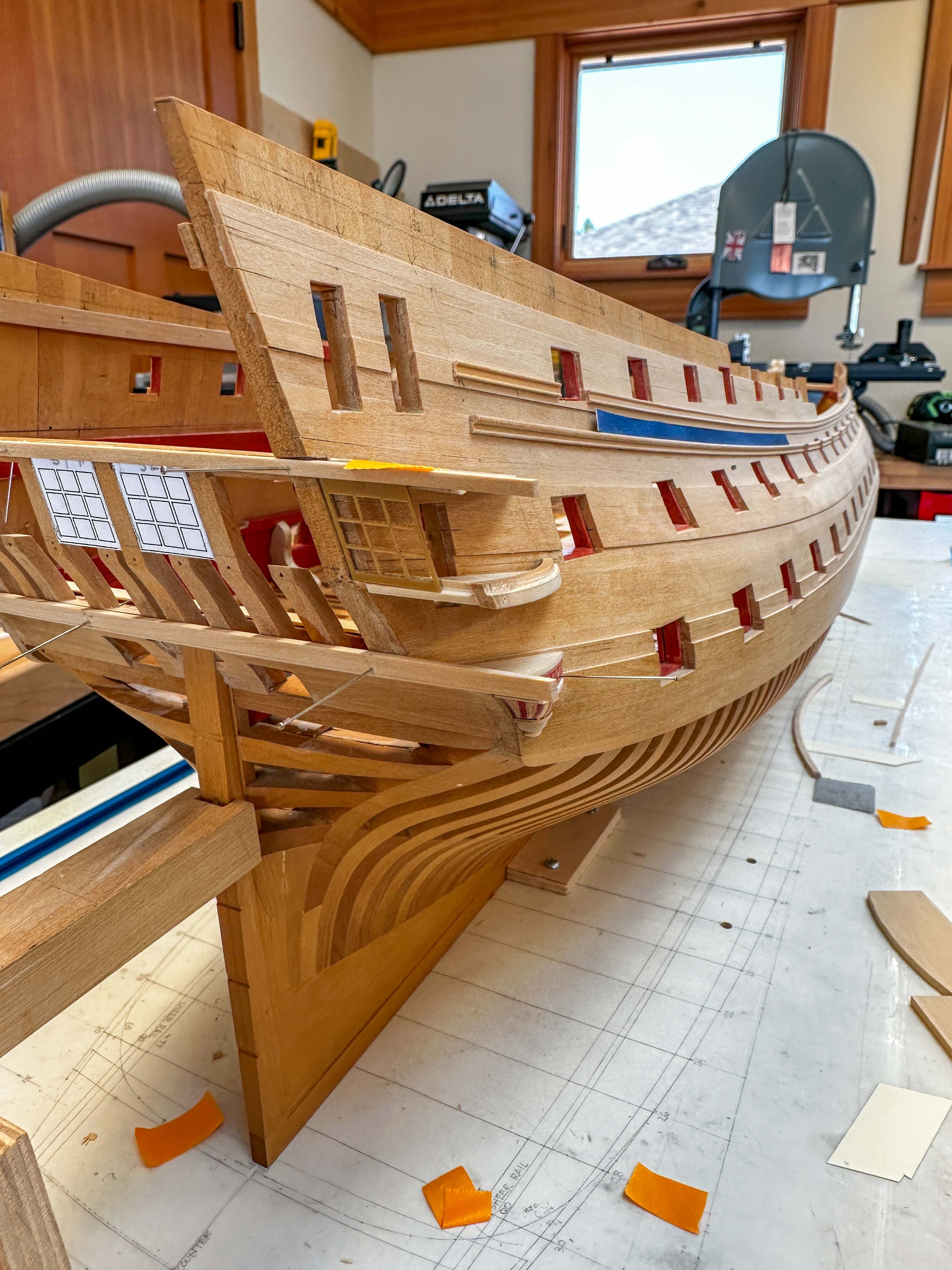
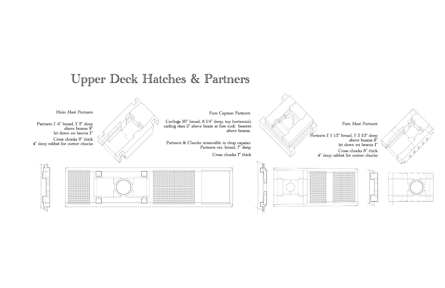
Pirate Adam, Dave, Druxey, JD and Amalio, thanks so much for your kind welcoming back comments. This really is a genuine community. JD, I did work for several months at my computer with it propped up on a stool on my desk. Unfortunately, my shop work surfaces are not moveable, and so I work for a bit, lie down a bit, then work again. More doctor visits coming up, hopefully we can get this finally resolved. Amalio, I have so far drawn the Bellona for my own modeling purposes, and also because I like to draw. I am not sure they are in a state where I could reliably say they are complete and consistent. I am also not sure what copyright issues would be involved in selling these, since they are derived from prints of the original Admiralty draughts I obtained from the National Maritime Museum many years ago. And I don't want to get into running a business now I am retired. But I do want to share, where appropriate, back to this community that has helped me so much over the years to develop many of the details I have now incorporated. Here are a few more examples, first, the stern framing I am now working on in the actual model. A note of interest is that I found it necessary to suggest a false floor in the quarter gallery of the upper deck (the lower of the two). If the floor of the gallery were down on top of the lower finishing, it would be a long step down from the door cut in the bulwarks, as measured on the original plans. I imagine it would be a continuation of the upper deck in height and roundup. This is an interesting case of where they needed to resolve the different sheers of the outer bulwarks and the inner decks at this point. Further below, I am showing some of the hatches and partners on the upper deck I will be building at some time in the future. Interesting construction issues in these! Best wishes, Mark

-
HI everyone, I have not posted in many months, and want to catch up now. In anticipation of carving the figurehead, I attended the excellent workshop on carving run by David Antscherl and Greg Herbert in Annapolis in early October. Fired up with my newly acquired skills, I flew back home to Montana ready to carve, only to discover that I had pinched the sciatica nerve in my leg on the flight. I was unable to sit at all for several months, taking me entirely out of the workshop. After several months of physical therapy, I am finally able to get into the shop again in small bursts of activity. During that down time, I put my computer on a stool at my desk so I could work on CAD drawings standing up. I was able to draw many more of the details still to come. I will show some of those in some following posts. Here is a taste: The unexpected and enforced downtime due to medical issues caused me to realize that I have to get my skates on and work more aggressively towards completion. I may not have the luxury of working for many more years at the same leisurely pace. At the Annapolis workshop, Chuck Passaro discussed with me a number of ideas for tackling the most challenging pieces that were putting me into a tizzy, like the frieze paintings and the fretwork stern decoration, and I am beginning to pursue some of these ideas with him further. Thanks, Chuck, huge help! I am starting with the stern, and here is a sample of what I will discuss in a later posting. The time off from cutting wood also gave me time to think more carefully about the decorative scheme I will want to follow as I get to this level of detail. I decided at the very beginning that I wanted to show the Bellona as originally designed and built, based on the original Admiralty drawings and on the first Bellona model of 1760 that shows her mainly in frame with little decorative detail other than the taffrail down to the floor of the stern balcony, with no quarter galleries. I did NOT want to portray her as she looked after a major refit 20 years later and shown in the second, fully detailed and colored Bellona model with the coppered bottom. Not only did the latter model show the later structural changes like the changed balcony geometry and the railings along the roundhouse that I do not like, but its overall decorative scheme felt like it was more extravagantly Rococo and showy than the real ship would have looked several decades earlier (like ivory details sprinkled around, and exuberant carvings). So I have been looking at other models contemporaneous with the first Bellona, like the Princess Royal and the first Victory, both designed by the Bellona's shipwright, Sir Thomas Slade. In some later postings, I will explore this further, as it might be of interest for others who are attempting to reconstruct a decorative scheme from indirect sources. So anyway, back into the land of the living! More posts to follow as I am able to put them together. Best wishes, Mark
-
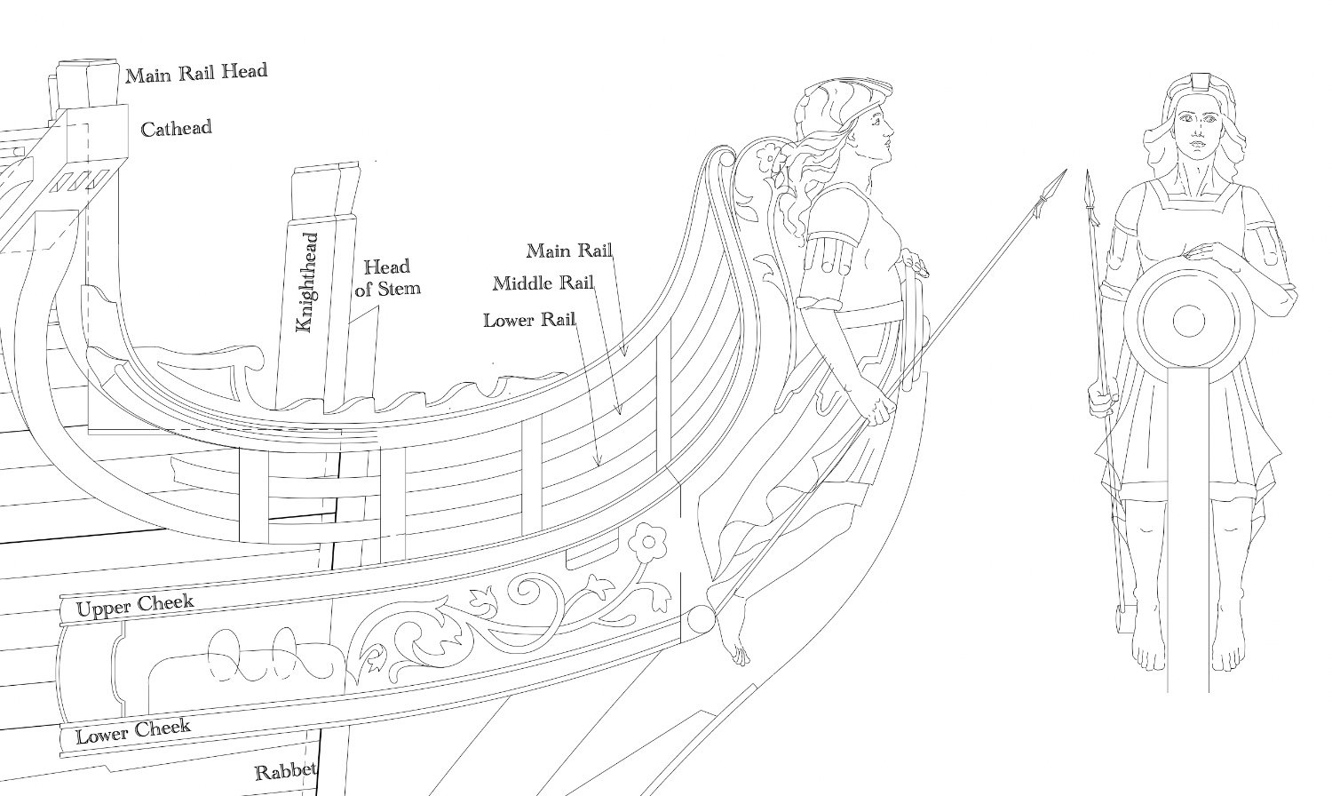
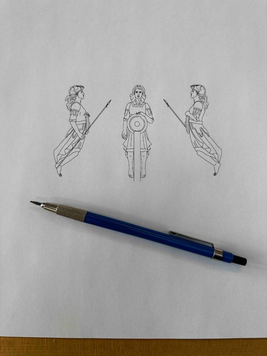
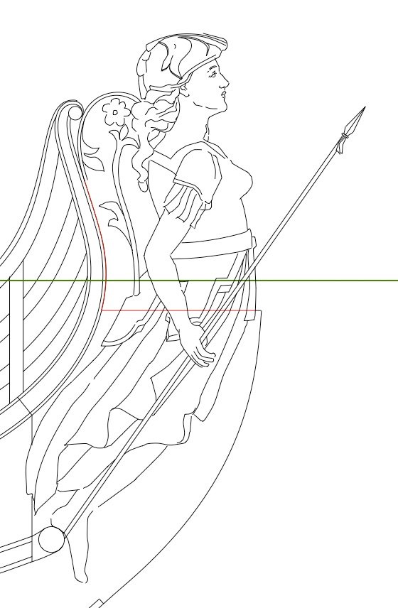
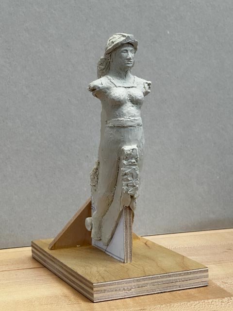
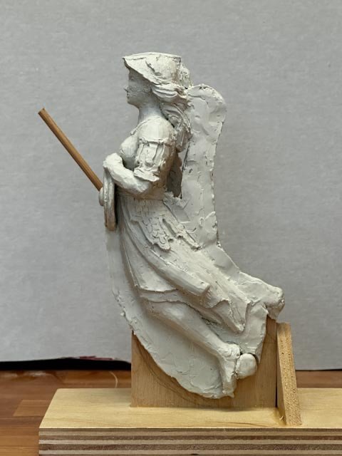
Thanks so much, Mark. I thought I would share my working process thoughts regarding the carving of the figurehead, for everyone including me who is daunted by the thought of this. After completing the double size maquette, I was ready to start carving. Then I realized that my original drawing of Bellona was a tracing over a photo of the Bellona figurehead on the first model. This is the one I discovered was much out of proportion, and with arms and hands that I kind of guessed at. This would not be a good drawing to work from on the actual wood. I knew I would have to redraw Bellona in light of what I learned in the maquette, to have a more accurate starting point for the carving. Here is the original drawing: Once I had a maquette, I took pictures of it, and then scanned these into my CAD drawing. This provided a better foundation for tracing a more accurate Bellona. Here is a photo of the maquette: And here is the revised drawing based on this. Comparing the two look in particular at the location of: the head (further back on neck; shoulder (further back on body), breast (lower and reshaped), width at waist and derriere (narrower, lower), arm location and proportion (hanging straighter, shorter lower arm), and the hand and feet. I struggled with drawing the hands and feet, until I hit on scanning images of hands and feet into CAD and tracing them. I took photos of my own hands, and found photos of feet online. Also notice in this drawing a new trailboard. This is many, many thanks to druxey, who drew this for me based on typical designs of the period. I know he has studied many models and drawings of this period, and he has provided me with an historically more accurate idea than I would have been able to do on my own. It was exceedingly kind of him to take the time to do this, and my model of the Bellona will benefit not only from his historical knowledge, but also his artistic eye. It is an honor to have this contribution from one of the key experts on this website. Thanks, druxey! Next step, starting to come to grips with laying out the wood blank. Here is the size of the figurehead I will be attempting: All for now, Mark


-
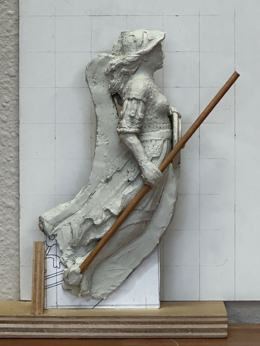
Thanks, Greg, I have been dreading it. Of course, I haven't yet tackled actually carving wood, which I am sure is a very different level of skill altogether in relation to shaping clay. I tried to keep track of the number of times I had to add clay to the form--lots of times--which of course I won't be able to do once I start cutting wood. It will be cut, cut, cut and it is still too short!
-
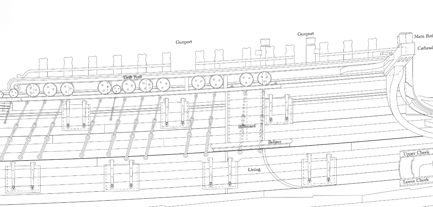
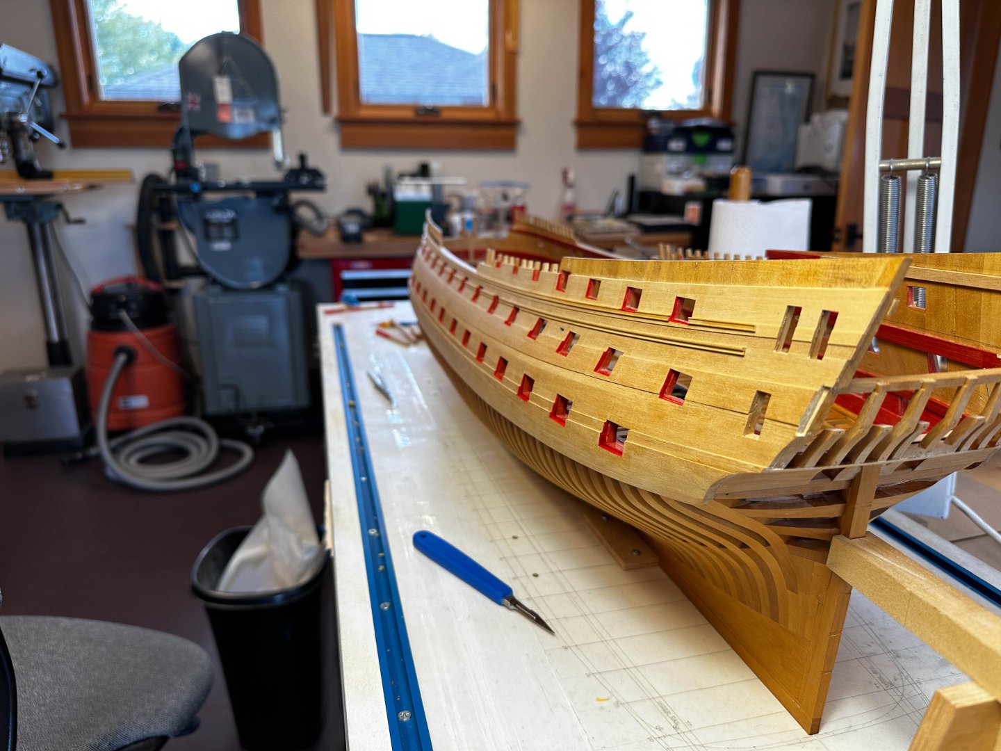
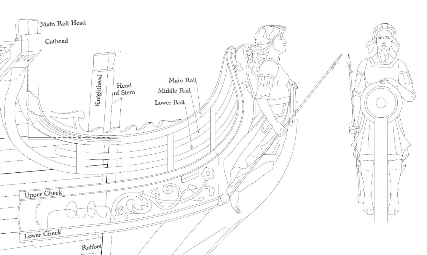
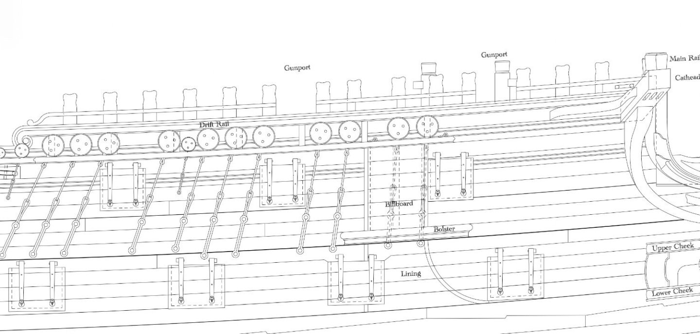
Thanks so much, Jason. This is my very first effort at sculpting the human form. The artist guides to human proportions helped enormously, then looking at examples of details like folds in clothing from other eighteenth century carvings. Yves, the Bellona has 28 guns on the gundeck, 28 on the upper deck, 14 on the quarterdeck, and 4 on the forecastle. At the time the Bellona was first launched in 1760, which is what I am trying to reproduce, there were no carronades. The four on the forecastle were long range nine pounders. They peek through short interruptions in the forecastle railing. I have labeled them below.
-
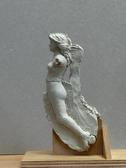
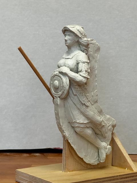
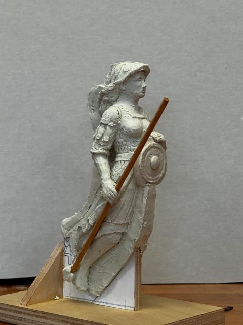
I just finished a clay maquette of the Bellona figurehead, at double scale, or 3/8" =1'-0". Here is a filler showing location and fit with the cheeks: Then taking the advice of David Antscherl's Fully Framed Models tutorial on carving, I used an artist's guide to dimensions of the female figure to get the right proportions of things, and initially modeled Bellona with no clothes yet: It is a good thing I did this, because I discovered that the original figurehead on the first Bellona model had lower legs way too short for the torso, minuscule feet, and a head pushed too far forward from the neck. To me, she also looks too cherubic to be the goddess of war: Since I had to add arms anyway, I looked at other artistic renderings of Bellona for a fiercer, more war-like look. I found a haunting image by Bertrand MacKennal of a sculpture in the Australian War Memorial https://es.m.wikipedia.org/wiki/Archivo:Mackennal_-_War.jpg. Mine is not as haunting, but as good as I can do, first go around: Next, reducing this by one half, and doing another maquette. I might try to do it in Sculpey so I can take measurements from it for the wood carving version after it is hardened. Does anyone know if Sculpey shrinks when baked in an oven? Mark
-
Thanks so much, Gaetan! Alan, would you be willing to tell my wife how important this is?🤪
-
Thank, JD, Grant and Gaetan, I have looked into microscopes (pun intended), after your suggestions to kit up. It is a world entirely unknown to me (somehow, I managed to get through all my school including college with never taking a life science class, only physics; so I have never even looked through a microscope). I need a little more information about what I am actually looking for. Reading some back issues of the Nautical Research Journal, I came across several articles by William Sproul who discussed his microscope, an old Bausch and Lomb Stereozoom 3 or 4 with a 10X eyepiece. If I have this right--and please correct me if I don't--you need a stereo microscope to enable your depth perception. Not all microscopes are stereo? And you need one with enough working depth under the microscope to allow the workpiece and the tools. He says he works at 7X to 10X most of the time. My Optivisor #5 is 2X, so that would make a big difference. Is the 7X to 10X range for the eyepiece what determines how much working depth there is under the microscope? Since my vise is sitting out in front of my bench, I imagine I need a boom stand. Or are you all using another way to fasten the work down underneath the microscope? I thank you all in advance for help on looking for a microscope! Gaetan, my dentist once showed me her dental loupe, which must have been a chirurgical magnifying glass. It sits in front of her glasses. Do you have suggestions about which ones would work for model making, and is the main requirement that it has a working distance of 10-20 inches? The ones I see online only seem to go up to 3.5X. Best wishes, Mark
-
Hi JD, I am using an Optivisor with a 5 lenses. It is definitely pushing my limits. As I get closer to what I think is finished, I take macro photos with my iPhone to see more detail than I can see with my eyes alone. then I clean up some more. I probably should start looking into a microscope as I start ramping up the carving part of this project. What do you use? Best wishes, Mark
-
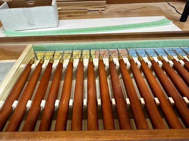
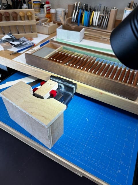
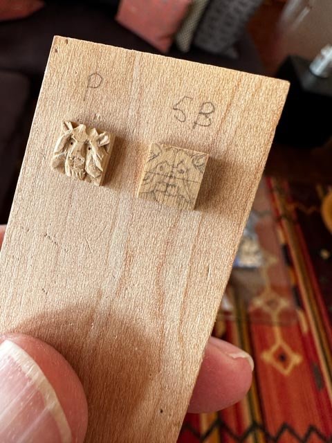
I finally made my first foray into miniature carving. I started with the lion heads on the outboard ends of the cat beams. 7.85 mm or 5/8 inch square, so tiny enough to keep me focused! I used my Russian chisels for the first time. They are as wonderful as everyone says. Super sharp, well balanced, controllable cuts. I glued 3000 grit paper to a hardwood block for sharpening. I have been able to sharpen freehand with success, using the fore and middle fingers to hold the chisel at the right angle to the block, and the fore finger to press slightly down on the cutting edge. It brings back the super sharp edge in only a few strokes. And it does have to be touched up regularly, like every 8-10 cuts. I haven't had to do the gouges yet. That looks more challenging, especially the .5 mm one. At first, I took chisels out and put them on my desk when switching to another chisel. I quickly found out that this does not work. First, they were all to easily starting to roll towards the front edge of my bench when I wasn't looking. Second, the cutting edges are so tiny that I would have to pick up each on on my bench to look very carefully to find the right one. I decided it was a better idea to keep them in their box whenever not in use. To facilitate finding them, I made a small chart and double sided taped it to the back of the box. Now it is very easy to find a chisel right away, and put it back safely between uses. I held these in my GRS vise. Its ability to pivot really helps get at the wood from the right direction. Since this vise mounts on the edge of the bench, I pulled out my sliding platform beneath the bench (that usually holds my cutting board), and built a small platform to sit on top the platform and around the wood block to be cut. This gives me something to rest my hands on as I try to control these very fine cuts. Gosh, a three dimensional figurehead doesn't look so scary after this!😏
-
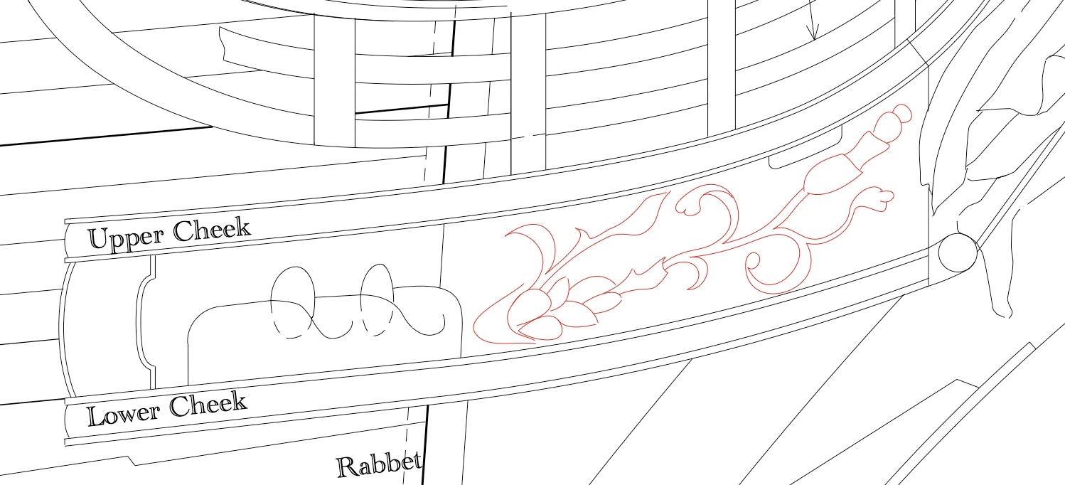
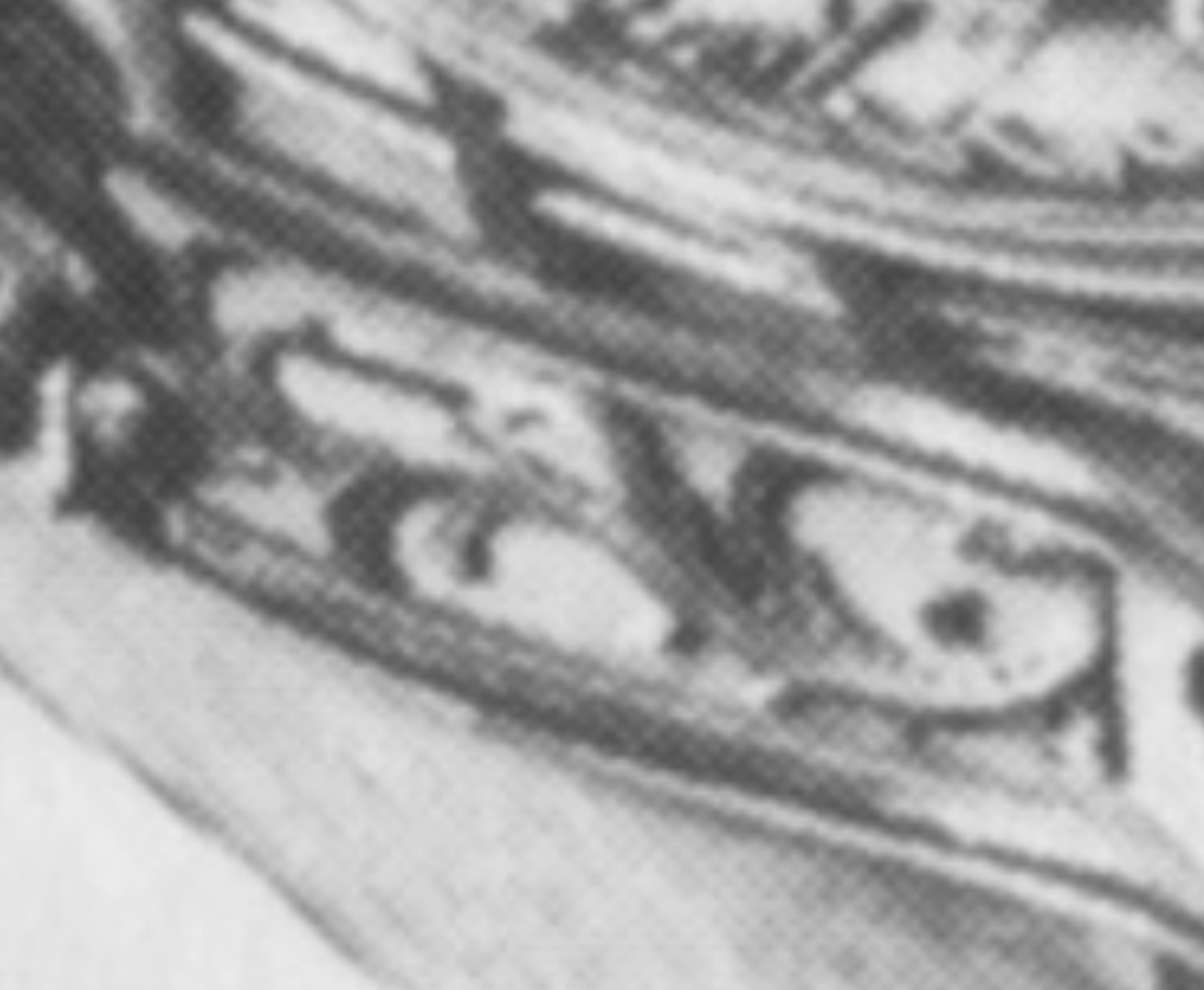
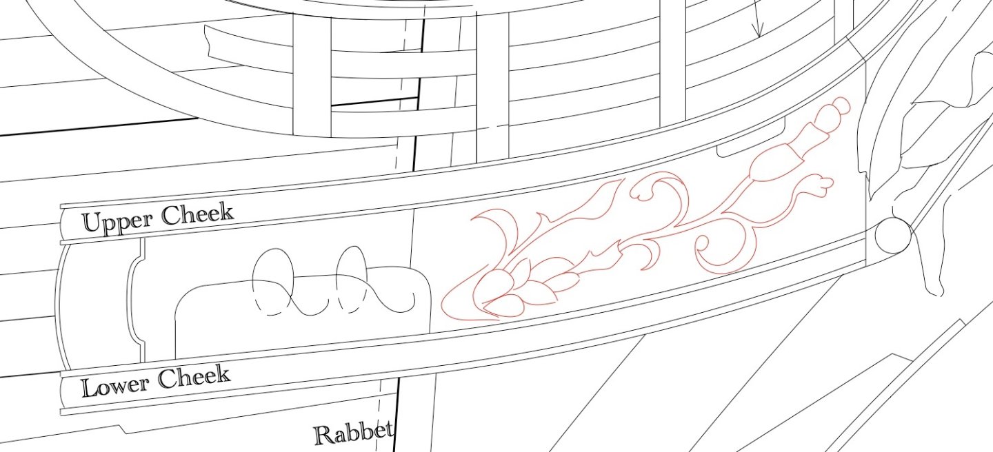
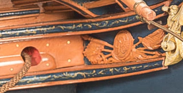
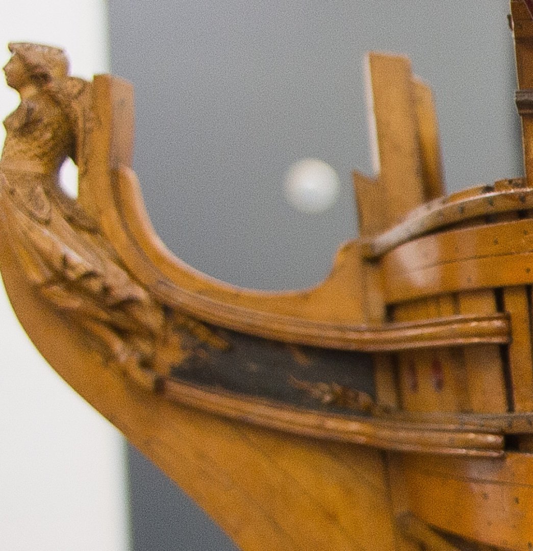
A small update on the traiboard question. In posting 2286 above, I showed the two different trailboards for the two different Bellona models. I wanted to follow the first model because it is closer to the original design (since it predates the second model by 20 years or so), but the only photo I have is frustratingly out of focus. I also looks like it lost parts in the center, and I could not imagine how to recreate the original design. Then I saw the trailboard for a contemporary ship, HMS Hercules or Thunderer, launched just one year before the Bellona, in 1759. This shows a floral scroll: So I traced what I could see of the remaining Bellona pieces, and speculated on how it might have been filled in in the spirit of the Hercules design. Too far down the road of speculation? At least it would be easier to make than the second Bellona model design, with its super thin spears, the George III cypher, etc.
-
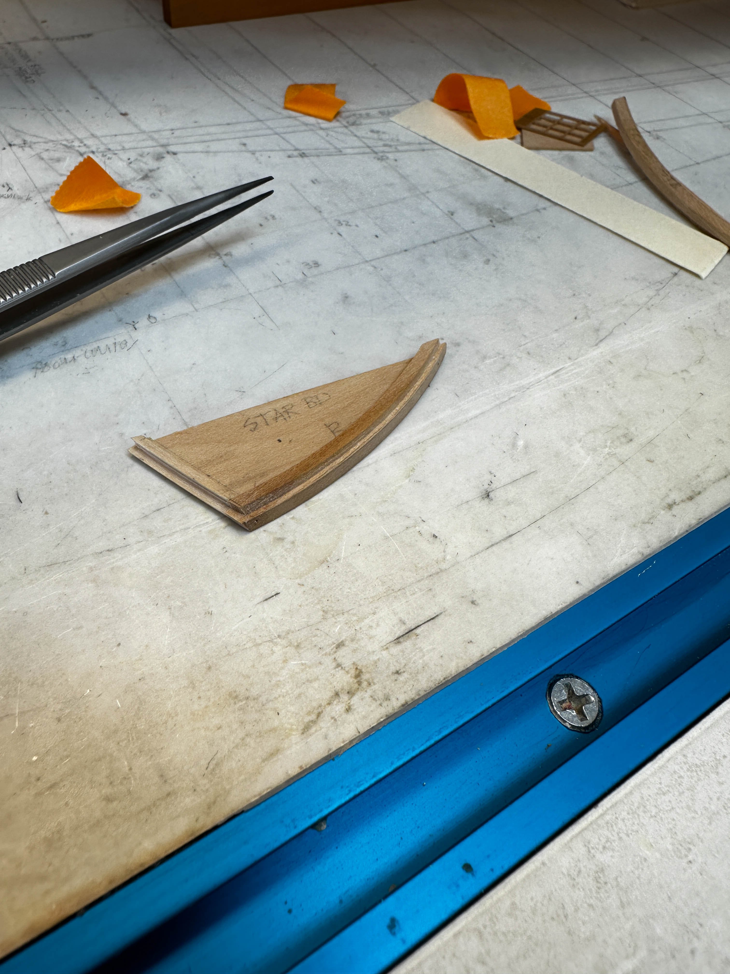
Hi Noel, Others more experience than I may have a better answer, but so far, I have used this trick for temporarily holding other parts together (for example, to shape a port and starboard piece at the same time for perfect symmetry), and I have had no problems with distorting or discoloring the wood. Using 99% isopropyl means it is mostly alcohol, and it dries quickly when the piece is removed from the bath. My biggest mistake was using too much glue. Only a tiny drop or two will temporarily hold parts together, and this is much faster to release than a full coating of glue. Indeed, I have given up trying to separate pieces that were glued too thoroughly together. Best wishes, Mark
-
Hi Alan, I like the idea of letting it release without having to pry two things apart. I'll try the PVA and alcohol idea. Mark
-
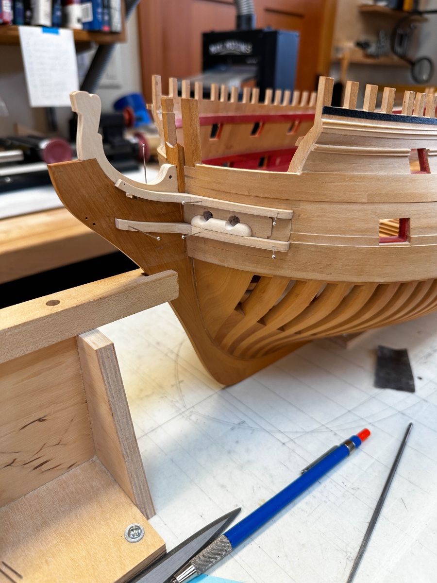
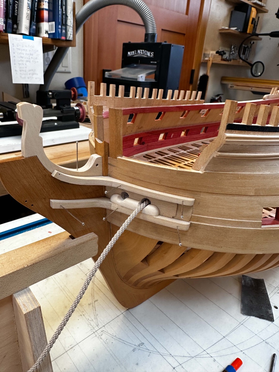
I have now drilled the hawse holes, and fitted a bolster waiting for final assembly for final trimming: I now have to turn my attention to the trailboard. I am getting closer to painting the blue around this area, and I want to know where the trailboards need gluing. I want to build the Bellona as first designed, and shown in the first model. But the trailboard detail is frustratingly difficult to see or to reconstruct, from the photo I took: Unless someone has a better photo, I may have to build the trailboard on the second Bellona model: If I do the latter, do you have any advice for how to glue this down to a backing board for piercing and carving, and then how to get it unglued from the backing board with those tiny, fragile pieces holding it together? Mark


-
Beautiful work, Siggi. Your craftsmanship is spectacular, and your carving and painting set the very highest standard for everyone else. I wish you could offer lessons in your techniques! Mark
-
Marc, I really appreciate how you are as interested in the history and rationale for various reconstruction decisions as you are in the exquisite model construction itself. The best of both worlds! Mark
- 2,695 replies
-
- 3
-

-
- heller
- soleil royal
- (and 9 more)
-
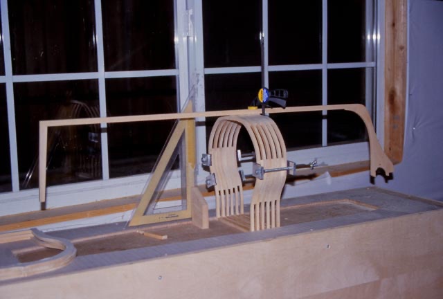
Hi Alan, You might have a look at some conversations about this problem at my Bellona website. In posting #173 (about page 6) and onward, is a discussion about the stern roundups. I found out years later in Steel's Naval Architecture that the roundups of the beams at the stern of the upper deck and quarterdeck are indeed intentionally higher than the standard beams further forward on each of these decks, for the aesthetic reason druxey described. These are faired in smoothly so the deck does not have a bump in it at any place; but it means that every beam from the stern to the point of fairing into the standard beams is a slightly different roundup. Sneaky! I kind of faked mine, making beams a little larger and then smoothing down the upper deck surface. I didn't understand why at the time, but got there in the end. I think.... In posting #198 and onward, I show a jig I made to manage all of the roundups and arrangements of the vertical stern timbers, to keep everything in place and symmetrical. A lot of work to make the jig, but then everything fell into place very quickly. Hope this helps! Mark
-
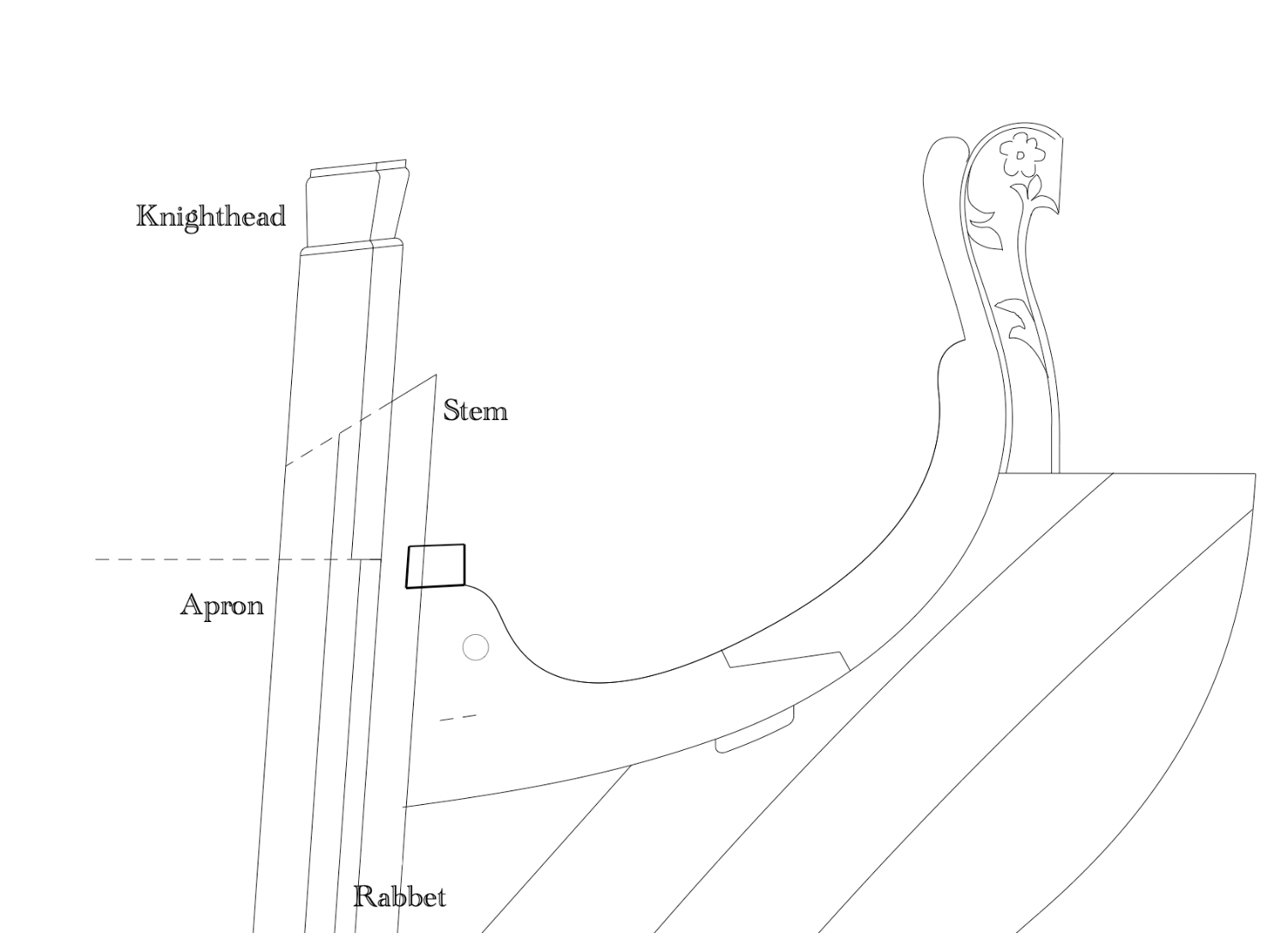
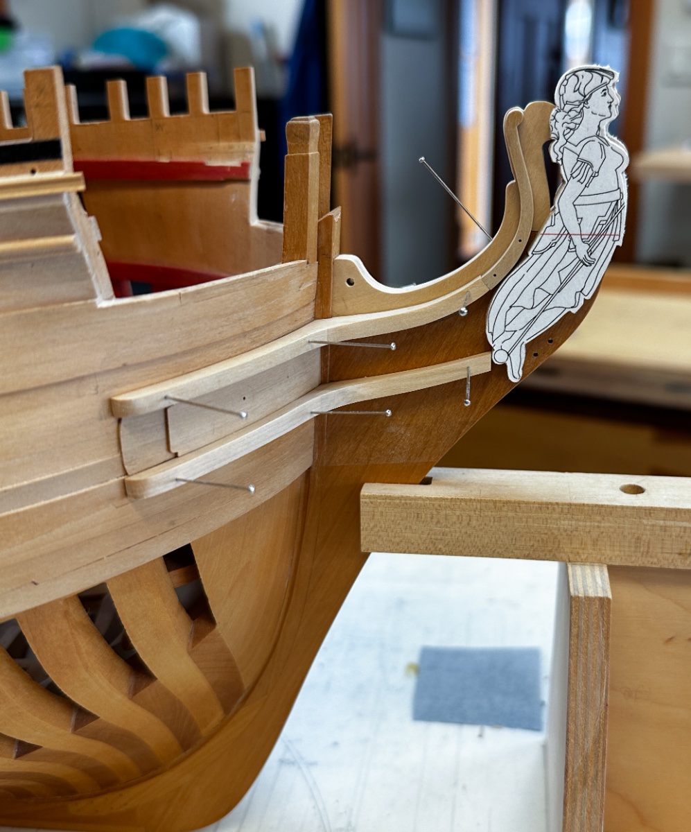
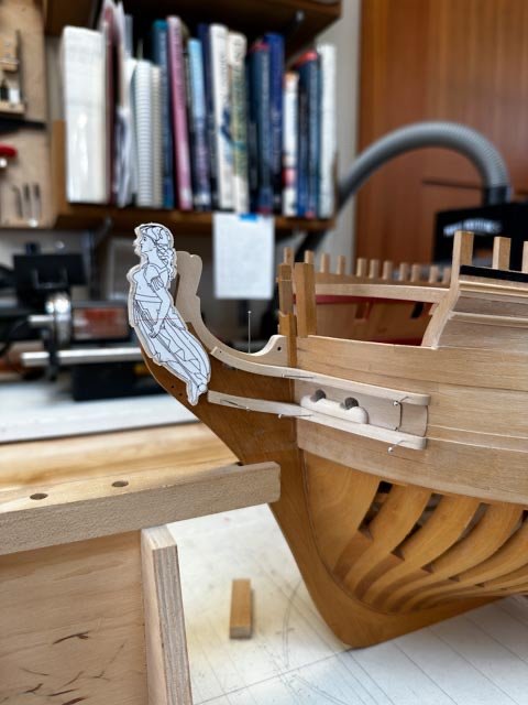
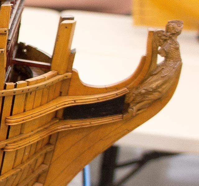
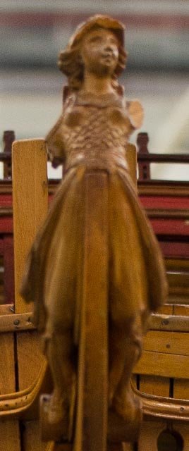
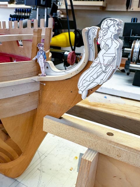
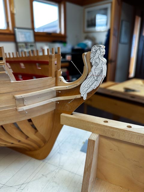
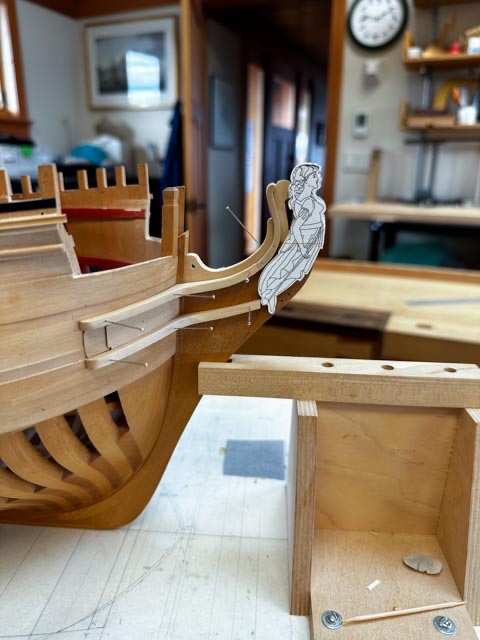
Thanks so much for the kind comments, Yancovitch and Steve. Slow but steady! In my last post, I express doubts about the way I had managed the hair bracket, sitting tenuously on top of the knee at the stem. After pondering it a while, I decided there was nothing for it but to cut down the top of the knee that I had shaped in 1998 when I started construction (see image below). It was too short for the hair bracket, the gammoning slot and the hole for the mainmast stay collar were in the wrong locations. To this day, I don't quite know how I got that so wrong. I might have copied something out of Lavery's book on the Bellona, which I have subsequently discovered is not accurate enough to build a model from. And I started construction years before I finally started drawing more accurate drawings--always a mistake! So, I made a complete new piece, combining the hair bracket and a carved ornamental piece that stands directly behind the figurehead. It seemed more solid the two together, and they are the same thickness relative to the figure head: And after a lot of faying and tapering, the new core for the hair brackets now holds everything firmly together. I made up a dummy of Bellona (don't tell her I said that, she is supposed to be a very scary warrior...), just to see how things are starting to fit together. The first image below shows the new core piece still covered in the paper pattern, showing the bas-relief carving to come on the piece behind the figurehead (she is pulled away from it a little in this photo). It also shows the captain standing on the cheeks. Gives a good idea of the size of the figurehead. And here are parts starting to fall into place: I have been reading David Antscherl's excellent explanation of how to carve a figure head in Volume II of the Fully Framed Model. I might start with the maquette, and see how it goes... I have pondered what wood to use, to carve the figures on the ship. My boxwood is not buxus semperivens, the stuff the old modeler's used, and that David recommended when he first wrote his book. But I can find no supplier anywhere in the world of buxus semperivens anymore. I know my boxwood is from South America, but I don't know its actual species. It seems to be stiffer in relation to what others have written about working true boxwood. I think it will have to do. And I can always blame a bad outcome on bad tools or bad wood, not lack of skill!🙂 Best wishes, Mark edited with higher resolution image here:


-
Marc, Thanks so much for finding that video. Astonishing. One of the most striking items for me is the frame construction system. It does not use sistered frames and a frame and space arrangement as in the 18th century English ships. The single frames abut each other, alternating floors with futtocks and eventually top timbers. It is framed just like the English Admiralty dockyard models of the 17th and early 18th century. Franklin's Navy Board Ship Models book discusses this full size practice as the likely source for this modeling technique, and now I see it firsthand. So the framing of my model of the Bellona replicates this actual practice; I hadn't quite realized that before. And you can only imagine what it was like to construct this before chain saws and cranes.... Mark
- 2,695 replies
-
- 4
-
-
- heller
- soleil royal
- (and 9 more)