SJSoane
-
Posts
1,648 -
Joined
-
Last visited
Content Type
Profiles
Forums
Gallery
Events
Everything posted by SJSoane
-
 Hi druxey and Mark, It is nice to be back. Not quite over the covid, but fast getting there. I didn't see any warnings on my power tools not to use while suffering from Covid, so onwards I go! It really does seem irrational that the rail on the face of the Sheer Strake is not called the sheer rail. But digging into this, I have now discovered three contemporary sources from about mid 18th century, all seemingly calling this the waist or waste rail. There is Falconer, sometime before 1769 calling the top rail a waist rail; the HMS Berwick Contract 1768 I quoted earlier, and the Marlborough Contract, 1763, which says: "To have a Sheer Strake Wro't fore & Aft, the upper Edge of which to be the Upper edge of the Waste Rail in Midships & 1 Ins higher from the Drift Fore & Aft, to be in Breadth 12 Ins and in thickness 4 Ins this, that the Channels be placed on the lower part thereof..." I liked Mark's interpretation that the Berwick contract was really talking about parallel rails, not necessarily the location, but the Marlborough Contract doesn't seem to allow for this. It has the top edges of the Sheer Strake and the Waist Rail aligned with each other. And yet, by the time we get to the Ship Builder's Repository, 1788, page 270, we have "Sheer Strakes, 2 in number, each in breadth 12", the upper edge of the lower sheer strake to be agreeable to the upper edge of the sheer rail." Now all is well, and this is later restated by Steel who also has the upper rail as the sheer rail. I wonder if there was a transition at mid century, swopping the names to be a little more rational. And I can't stand the irrationality of a waist rail over a sheer strake; whatever really happened here, I will call my upper moulding a sheer rail, to match the sheer strake under it! Best wishes, Mark
 -
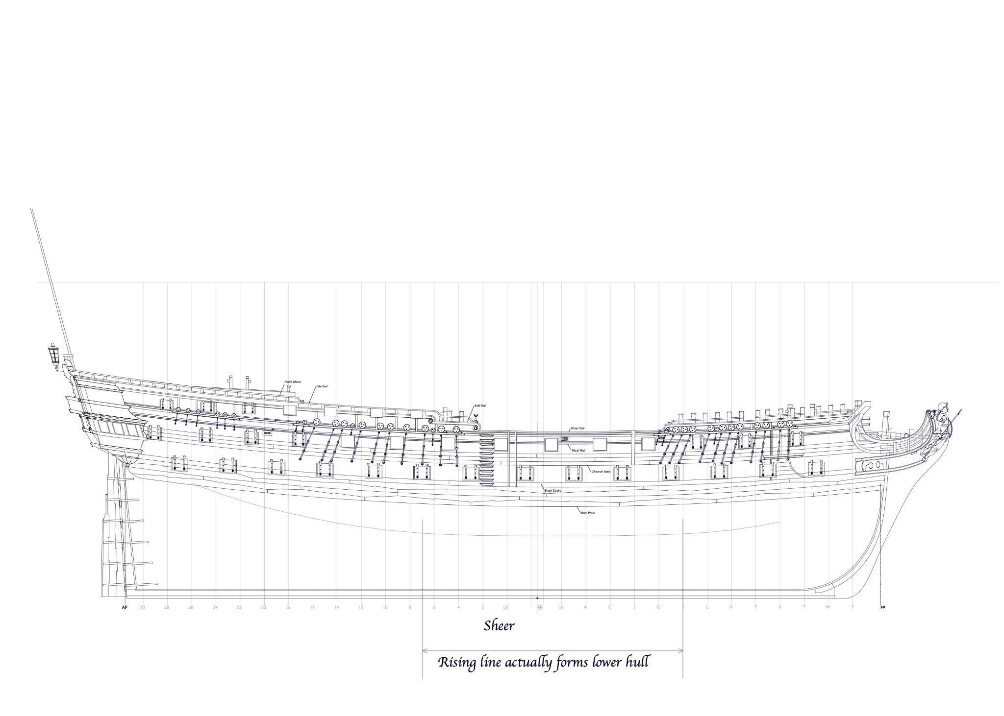
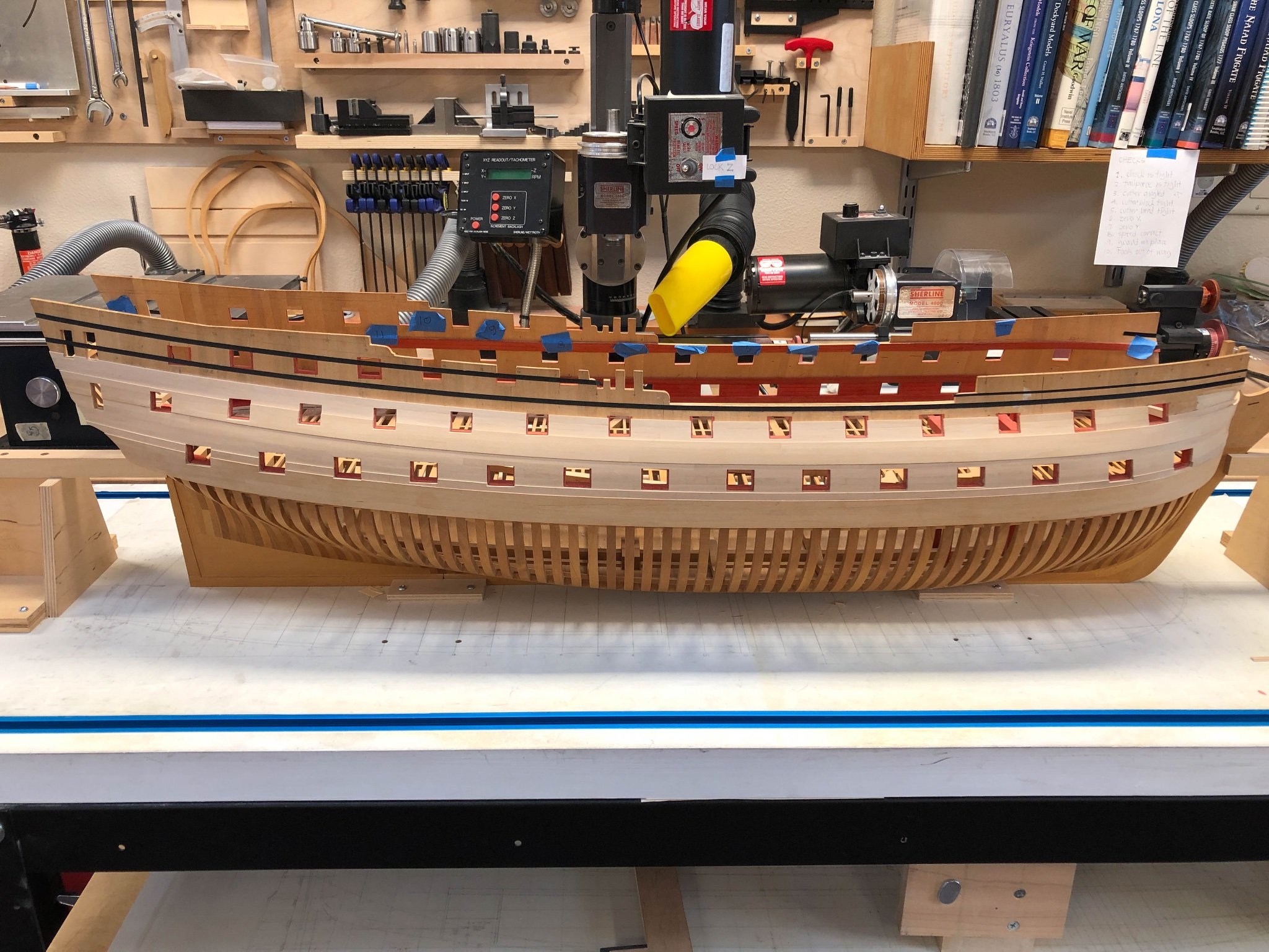
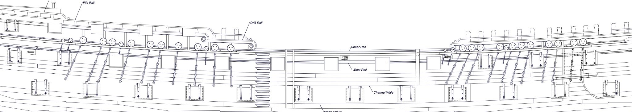
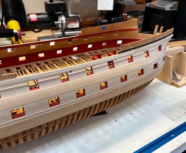
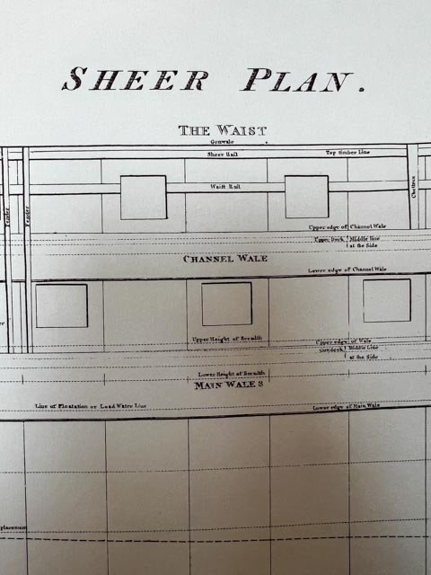
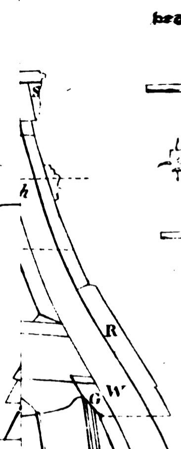
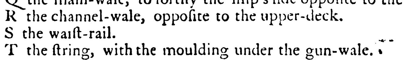
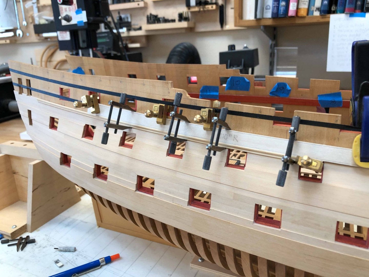
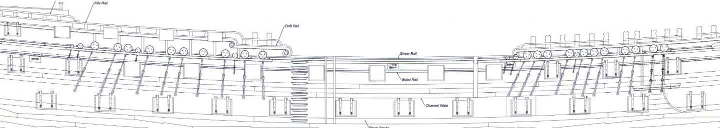
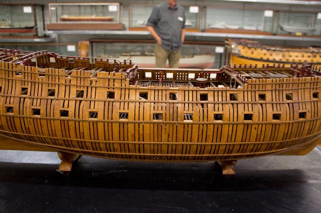
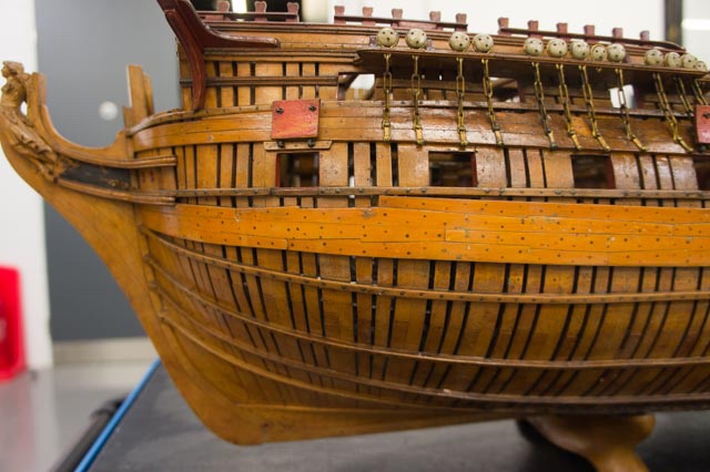
Hi everyone, A long, long time away from the Bellona! Other life things have interfered, including getting Covid even though I had both vaccinations and the booster. But hopefully things are getting going again. I am up to the top plank in the waist, the Sheer Strake: And I have come across an interesting question regarding the sheer and waist rails as I tackle this part of the ship. Siggi first alerted me to this, and then John directed me to the contract on the National Maritime Museum website for the Bombay Castle, which was based on the Berwick, which was a sister ship to the Bellona, and the contract Brian Lavery believes is closest to that for the Bellona. Here is the puzzle. I have long assumed that the uppermost plank in the waist is the thicker Sheer Strake, and nailed over it is the uppermost moulded rail named the Sheer Rail; and that the Waist Rail is the moulded rail below, cut through by the ports as seen in my model above. This is how they are names in Steel's plate: And Goodwin's book, The Construction and Fitting of an English Man of War, page 57, also labels them as Sheer above, Waist below. But, Siggi pointed me to Falconer's Dictionary of the Marine, which clearly labels the top rail as the Waist Rail: And then I looked at the Contract for the Bombay Castle, which cannot make any sense if one assumes that the top Rail nailed on top of Sheer Strake is named the Sheer Rail. It clearly refers to this top rail as the Waist Rail. "Sheer Strake: To have a Sheer Strake wrought in two breadths that the upper Edge of the upper Strake may be agreable to the upper Edge of the Waist Rail in the Waist and one Inch higher from thence forward and from the Waist aft to be in two Breadths 12 Ins and 4 Ins thick and of English Plank in Wake of the Channels". (both models of the Bellona, BTW, show just one strake for the Sheer Strake, not two.) Further in the contract, the Rails are defined as follows: "The Sheer Rail to be 8 inches broad and 3 1/2 thick the Waist Rail 7 inches broad and 2 3/4 thick the Rails in the Drift to be 6 inches broad and 2 1/2 in thick. Since the rails in the Bellona sheer drawing appear to be widest below and narrowing as they climb higher, this suggests the Sheer rail is the lowest, then the Waist Rail, then the Drift rails above. Interesting, when our primary sources of Steel and Falconer disagree, while the contract agrees with Falconer as best I can see here. Maybe they didn't mind naming the rail over the Sheer Strake the waist rail, and the sheer rail is the one down below! Perhaps they tripped up apprentices with this one.... Best wishes, Mark
-
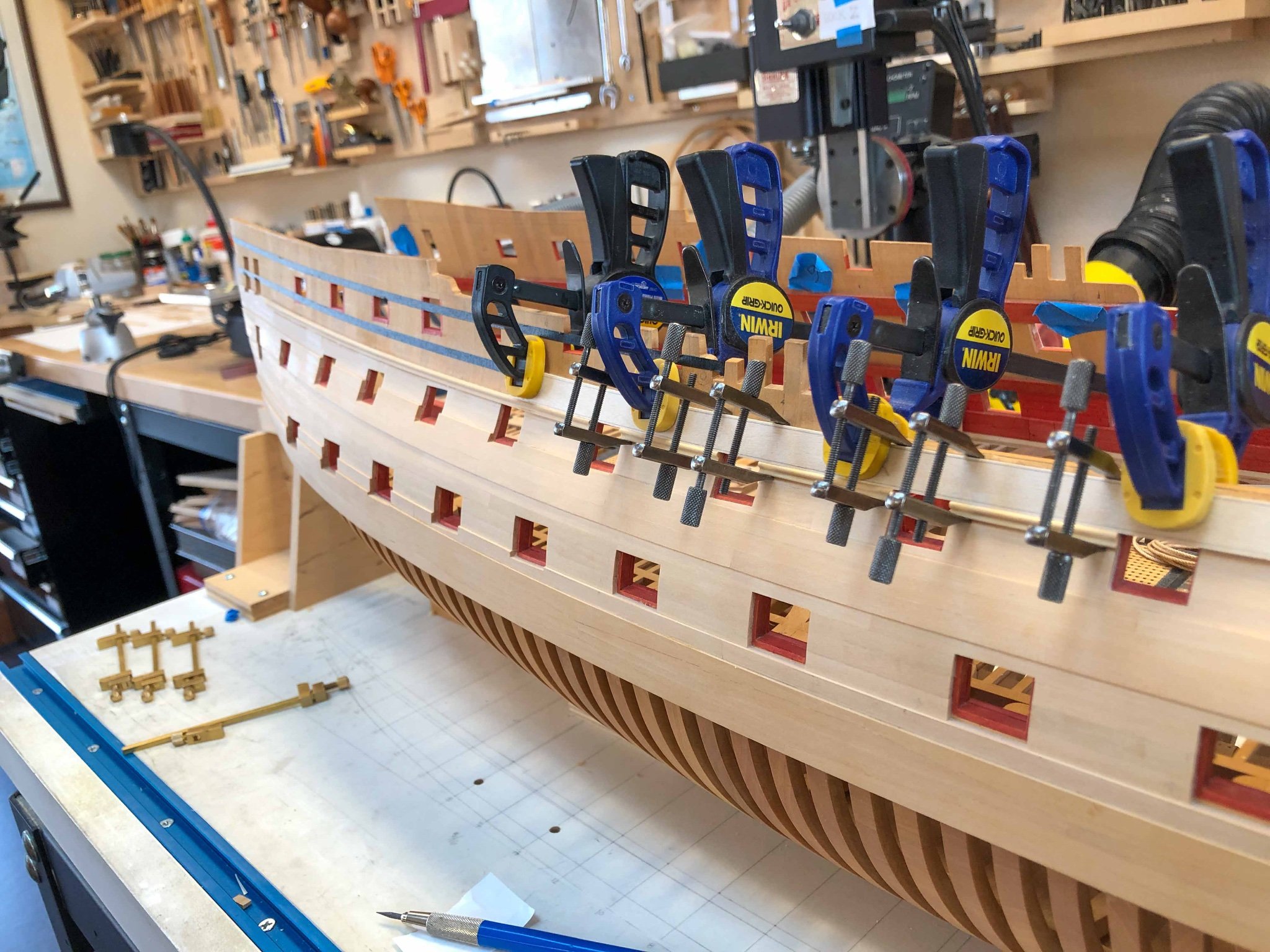
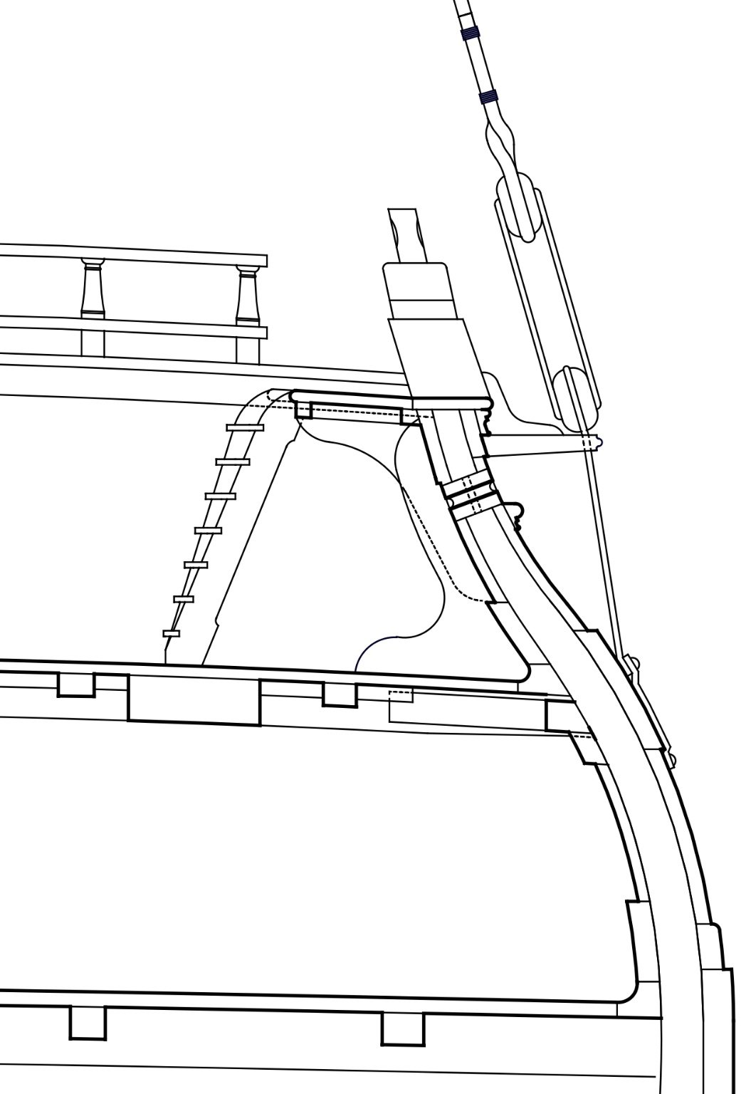
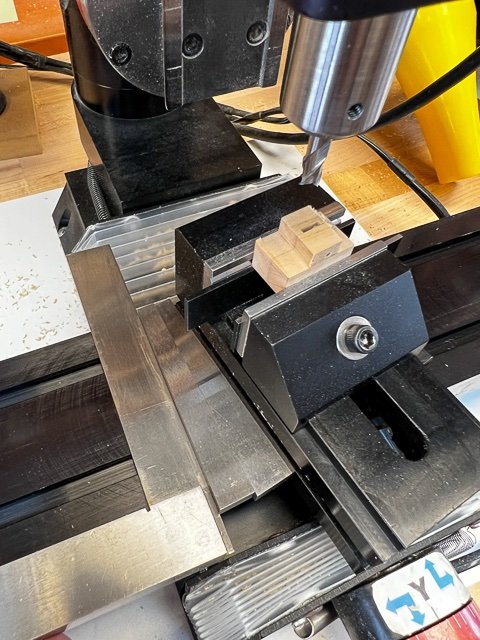
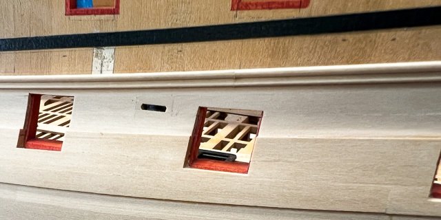
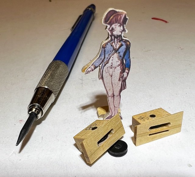
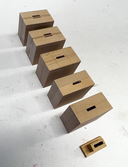
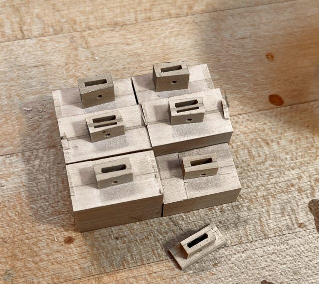
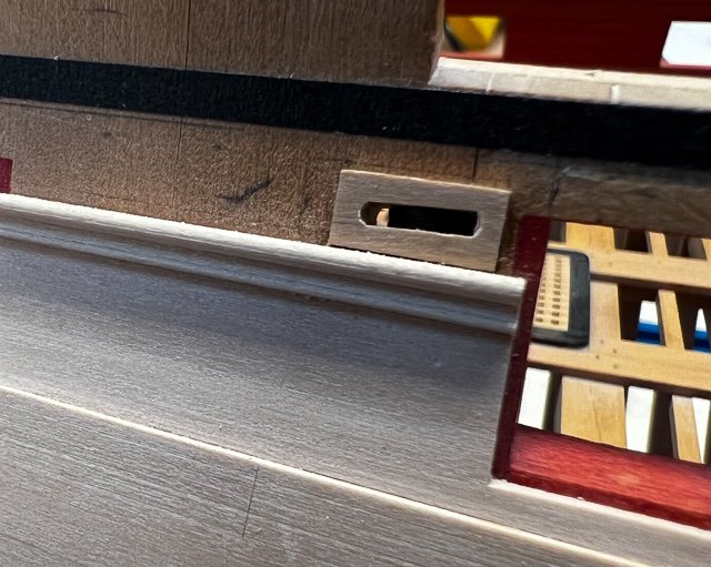
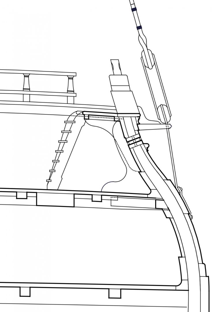
Hi everyone, Well, it has been a long, long time since I last posted. A number of life-outside-the-shop issues took over, but I am back to the Bellona at last! My plan of work now is to complete the planking and all outboard work, so I can paint the wales and friezes with the hull on its side. Then I can install the lower deck guns and proceed at last with the upper deck. With the lower deck guns installed, I would have no hope of turning the hull on its side for painting. As I got closer to the top with planking, I realized that I would have to install the sheaves (main sheet and tack, fore sheet, sprit topsail sheet) in the sides before the next strake could go on. I thought this would be a fun, short break from planking. It turned out to be over a month of work. They are way more complicated than I ever realized. And I made several mistakes in their fabrication that meant starting over. First the complication. The sheaves on the Bellona are neatly slotted between the sheer and waist rails outboard; and they slope at right angles to the side to arrive inboard just under the clamp. The inboard edge also swings up the fay to the underside of the clamp: And the block in sheer is a symphony of angled lines. The top and bottom of the blocks correspond the sheer line of the hull at their respective locations; the sides are vertical; the sheaves are angled within the blocks to provide a fair lead for the lines: How to construct these? Since I did not have any router bits that could cut a slot thin enough, I created the slots by laminating blocks, with a groove cut in the side of one with a mill bit. For the double sheaves I laminated a thin sheet in the middle of the block. While the blocks were still square and the slots were parallel to the top and bottom, I drilled the holes for the sheave pins. At first, I tried mounting the blocks on my Sherline rotary table on the mill; thinking I could just dial in the appropriate angles in one go. But I simply could not visualize which way angles went relative to each other, and I also stupidly misread the scale on the rotary table, cutting .3 degree rather than 3 degree angles. I ruined several blocks until I discovered this. The sheave hole in the block at the bottom of the previous photo was supposed to be sloped and you can see it is parallel .... To make life easier, I turned instead to using my angle blocks to set up the mill vise at the appropriate angle (see the angles against a square in the photo below). This helped me physically visualize which way things should be aligned. And then I used a mill cutter to cut first the ends and then the sides. the block at the bottom of the photo below is an example of the failed blocks relative to the correct ones with angles: And then trimming to get the blocks to their correct sizes. I turned the sheaves in ebony, and used a tiny round file to ease the ends of the slots. Note how the tops of the blocks in the photo below have angled tops to the inner surface; this is to fay to the bottom of the clamp, as seen in the first photo posted above. Also notice how large these puppies are next to my captain. They are tiny in my model, massive on the ship. I can see the laminations on the blocks more than I would have liked; but these are all under the frieze painting and so hopefully this will disappear. They are dressed proud where the next strake of planking will come up to them: But the main sheet sheaves had to be cut into finished planking (it did not occur to me to deal with this when I was planking lower down). These were very laboriously cut into finished wood, with much trimming and fitting, trimming and fitting, to do this cleanly. It would have been better to think ahead before the planking was installed here: All for now. On to the next strake of planking. Mark

-
thank you, JR, for those additional references. I will try to track some down, and see if they give any greater insight into how the designer shaped the hull forward and aft of where the frame geometry still relied on the floor sweep. I am guessing it was a process of trial and error, and gradual experimental deviation from previous ship forms. And thank you, Chuck and Glenn, for your kind comments about the project. I still sit and admire the form of the Bellona's hull, and wonder at the skill of the designers who melded all of those complex curves together into something both functional and exceptionally beautiful. Mark
-
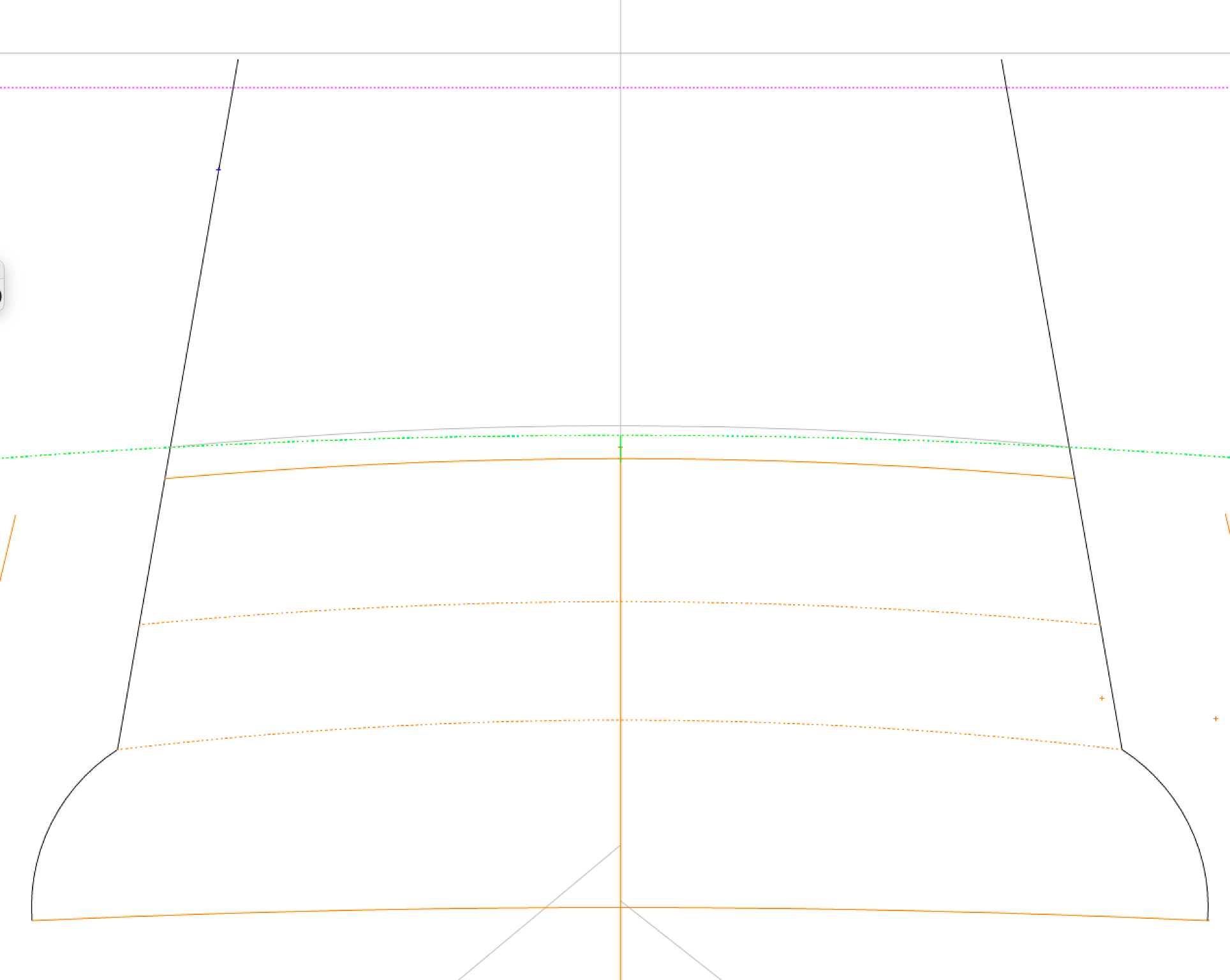
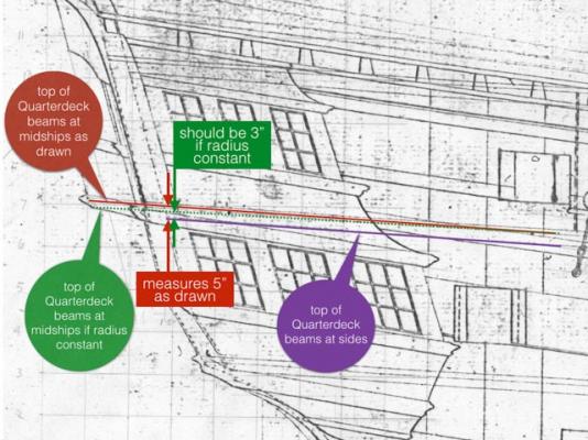
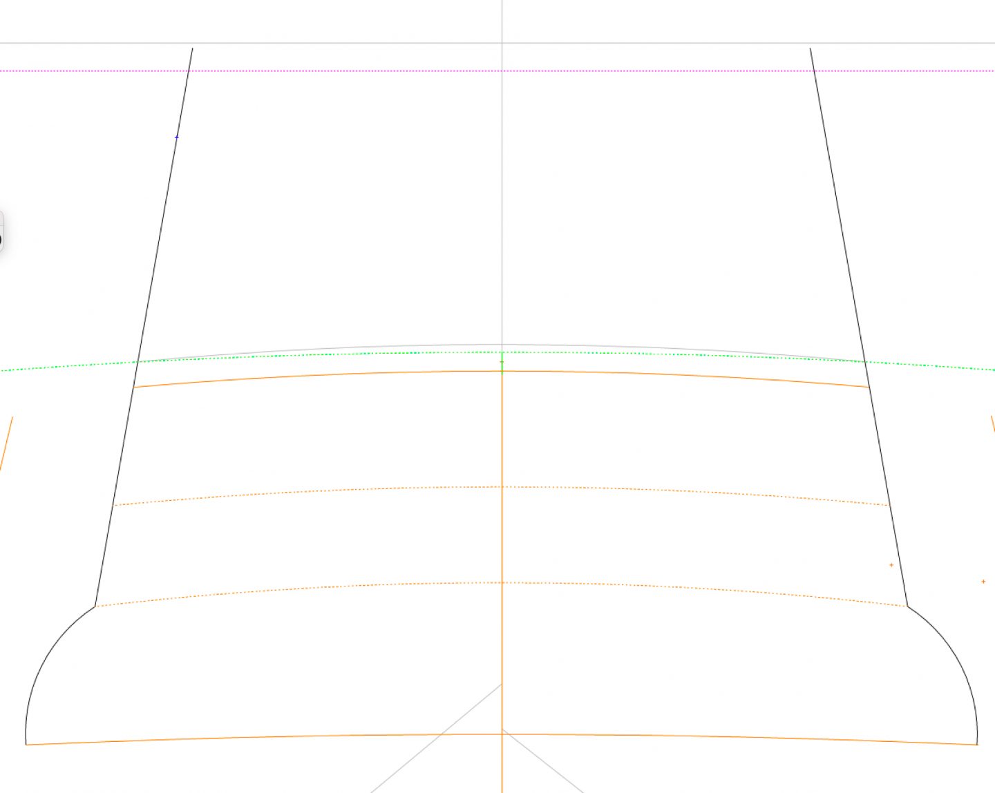
HI everyone, Drawing lessons from the Bellona, part II. I am quoting an entry I made in this log in 2014, when I and a number of people contributing to my questions were pondering why the roundup of the quarterdeck beams was actually higher in the captain's cabin than the roundup called for in the quarterdeck specifications. If the beams remained a constant roundup along the length of the quarterdeck, the crowns of the beams in the captain's cabin would have been almost 2 inches lower than they are actually drawn in the admiralty plans. Now almost 8 years later I can answer this definitively, after carefully following David Steel's instructions for draughting the drawings. And Ed Tosti, Greg Herbert and druxey figured this out 8 years ago, but I didn't understand it at the time. Now I do. Drawing the decks in sheer begins at the centerline of the ship and is an arc of a circle (only three points are specified to construct it; the heights at midships, and at the fore and aft perpendiculars. The height of the decks at the sides is NOT an arc of a circle, as I had previously assumed. One has to draw a cross section at midships, showing the maximum width of the deck and then raise a 5" line for the maximum roundup at this point. An arc of a circle is constructed on these three points. The width of every other beam is then drawn on top of this, giving a reduced height of roundup at every point. At the bow, when the width of the beam becomes zero, the roundup is also zero. This means that as the beams get rapidly narrower towards the bow, the roundup reduces and therefore the height of the beam at the side reduces just as rapidly. This causes the line of the tops of beams at the side--as seen in the inboard profile drawing-- to be a compound curve which rises more sharply at the bow than the stern and also more rapidly than the arc of the circle at the midpoint of the beams. This in itself is interesting, because the ports are a constant height above the beam tops AT THE SIDES, and therefore the ports' heads and sills are NOT on an arc of a circle, even though all of the rest of the sheer drawing (top timber, sheer line, etc.) are constructed as arcs of a circle. So there is a subtle mismatch between the ports and the rest of the sheer. But finally, as answering the question at the top of this posting, the instructions in Steel clearly direct the draughtsman to change the roundup on the quarterdeck to match the roundup at the stern windows, which is steeper. Druxey had alerted me to this, but again I did not understand this until now. Here are quotes from Elements and Practice of Naval Architecture p. 240 The heights of the decks must next be considered; for sometimes, in order to give depth for the lights, the decks are necessarily sprung abaft, and their round-up must be made conformably thereto. p. 245 Thus may the round-up be taken at as many timbers as may be found necessary, and set below the underside of the deck at its respective timber in the sheer plan; then, a curve line passing through those spots will represent the deck at the side : but observe, that the decks are to have a sufficient round abaft, to correspond with the round-up of the stern above the lights. And here we see it below. The green line represents the roundup of the quarterdeck according to its specified roundup for a beam at this point. The grey line above (and the orange line below, which is the bottom of the beam) is the roundup actually measured on the admiralty plans. In other words, the beams do rise higher than specified aft of midships, to align with the roundup of the stern windows. druxey explained this as keeping the stern design feeling light and springing, not drooping. Another example in the eighteenth century of art and form over-ruling function and constructional efficiency or consistency. No more drawing lessons now. Back to model construction! Best wishes, Mark

-
Thanks so much, druxey, for the spelling clarification. Steel was writing almost a half a century after the Bellona was designed, but I understand he lifted a great deal from earlier treatises (is this true?). And shipbuilding did not change radically over this period. So I assume much of this stayed similar, although I have to check things against the Bellona drawings themselves on a regular basis, even though they are crudely drawn by later standards. (more on that later).
-
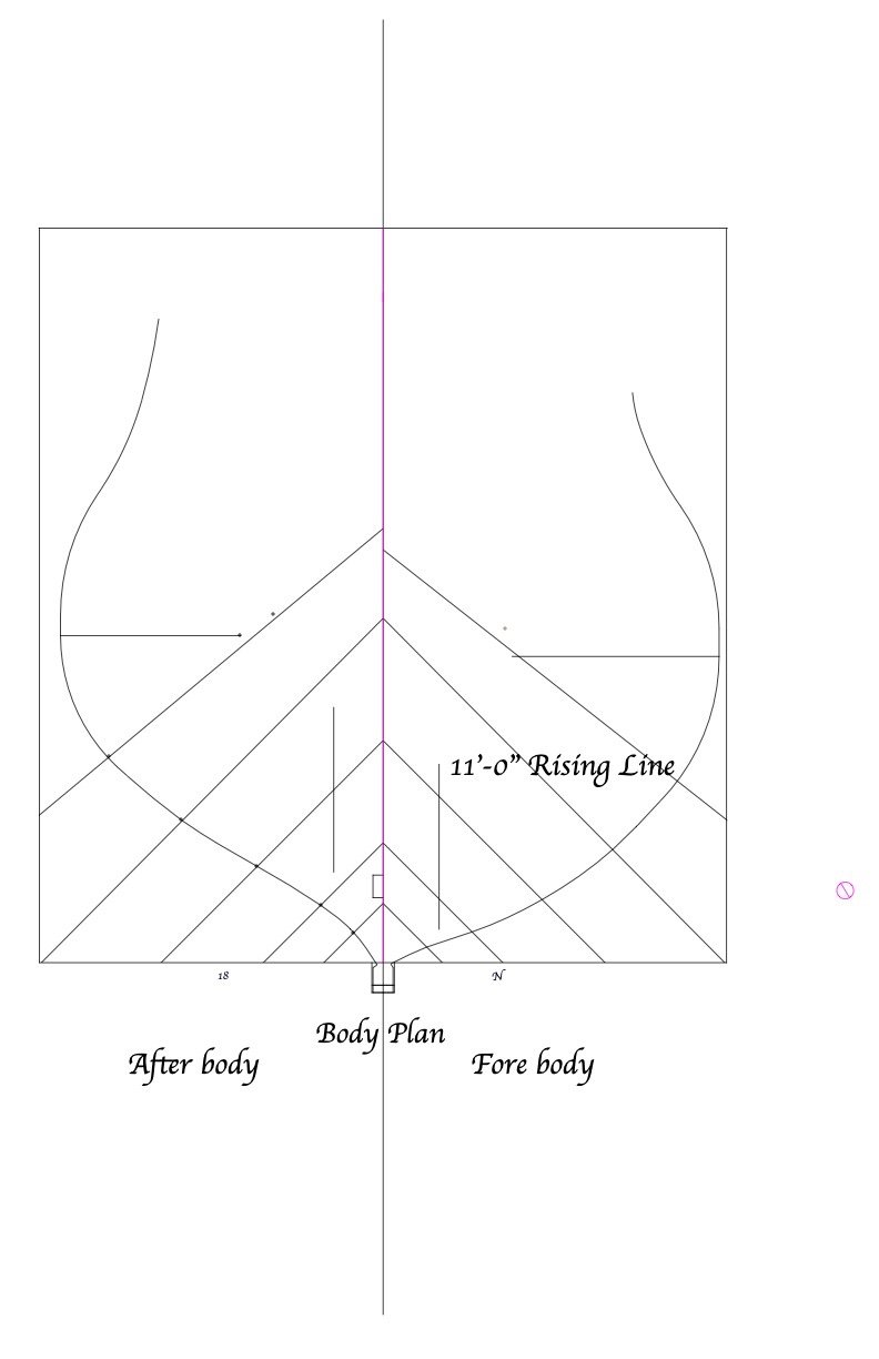
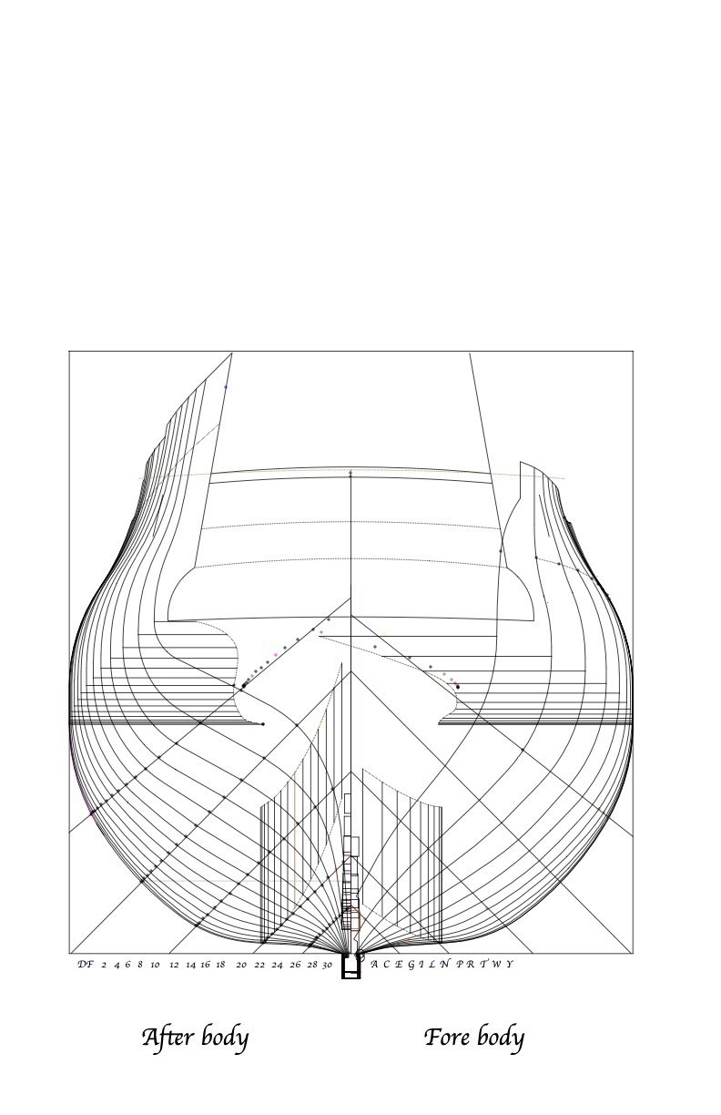
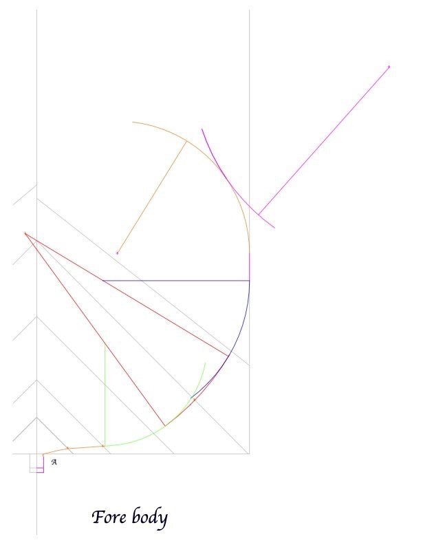
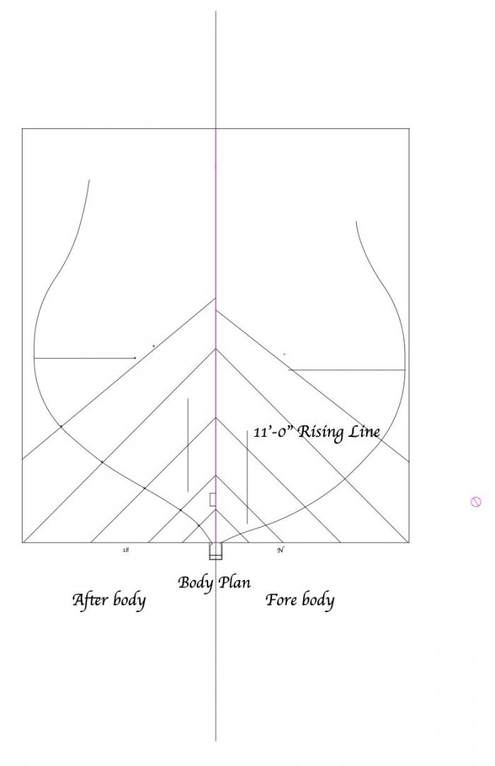
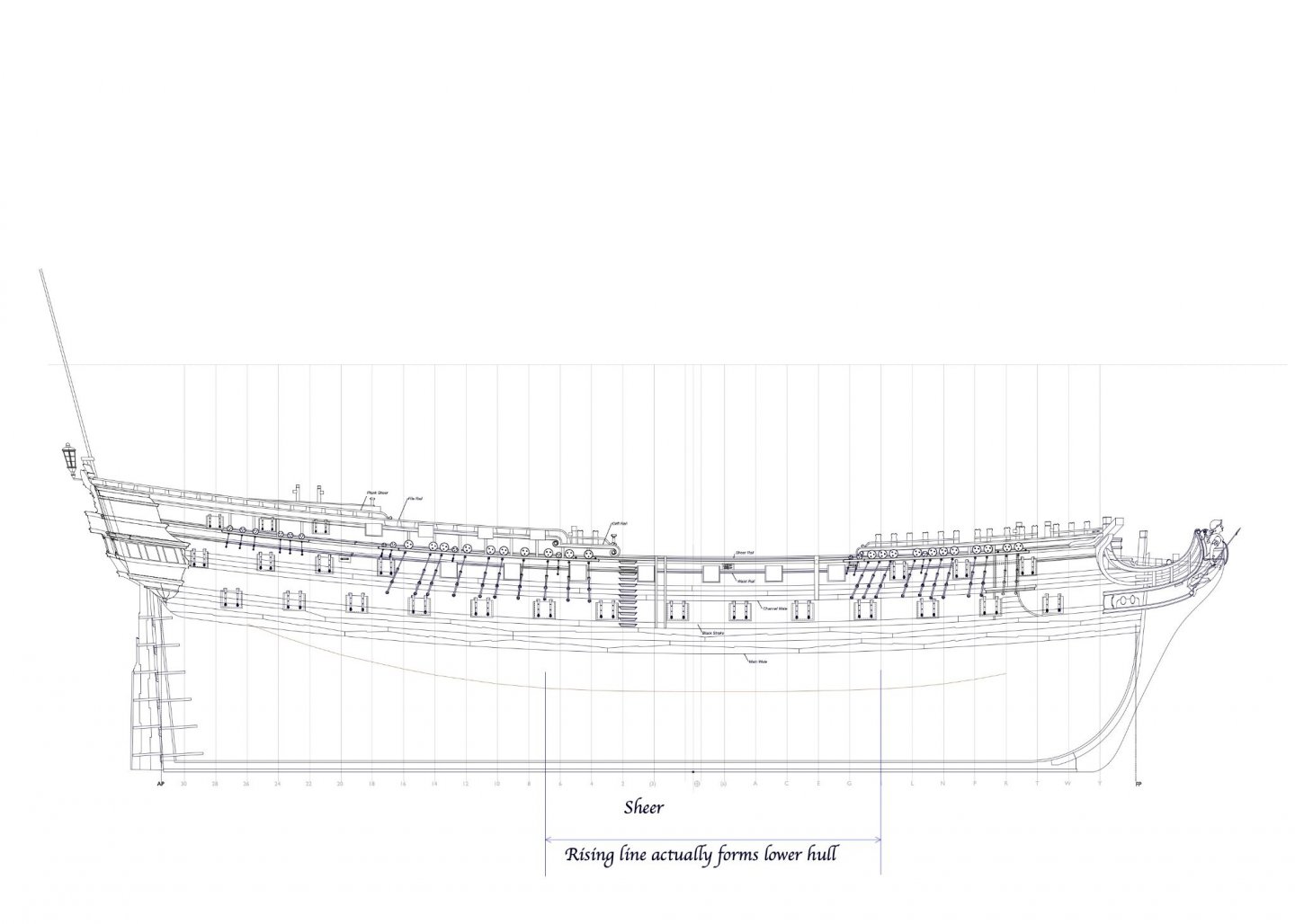
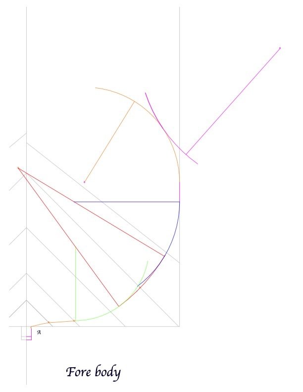
HI everyone, I stopped drawing long enough to share some of the things I have learned about the Bellona, and mid 18th century British ships generally, while following the 18th century drawing process. I will do this in a couple of posts, to keep to a topic at a time. And I will title these, Drawing Lessons from the Bellona, in the spirit of what lessons I have drawn while drawing! Drawing Lessons from the Bellona, Part 1. First of all, I want to acknowledge the essential help of David Antscherl's article in the Nautical Research Journal, Vol. 53, NO 2 Summer 2008, titled "Understanding Eighteenth-Century Admiralty Drafts: Making Contemporary Drawings Useful for the Modelmaker." This really helped me understand the principles and processes of these drawings. With this help, I turned to my facimile copy of David Steele's "The Elements and Practice of Naval Architecture" and followed the instructions given starting on page 234, Chapter III, Instructions for Delineating the Several Draughts and Plans of a Ship. The first thing I learned is that Steele does not explain how to design a ship, only how to draw one from "Given Dimensions" already set down by the ship's designer. How the designer determined a number of key design elements, like ratio of length to width, or heights of various elements from the baseline, or even the diameters of various geometrical elements making up a frame, remains a mysterious art. As an example, let's look at the cross section in the body plan. At first glance, this seems like a very straightforward geometrical process: A number of arcs are formed to create the frame shape. One of the most important, stressed in the instructions, is the "floor sweep" shown here in green. You can see here at midships that it forms the lower curve of the frame. The height of the centers of all of these arcs are shown in the sheer diagram as a line curving up from midships to fore and aft. The distance of these centers from the hull centerline are shown as a curving line in the half breadth plan, widest at midships and curving towards the center line fore and aft. The radius is a constant along the entire ship, 11'-0" in the case of the Bellona. So imagine a 22' diameter cylinder touching the lower surface of the hull, and then bending upward and inwards as it progresses fore and aft to help shape the hull form. Seems straightforward, plot the center on the body plan, and draw the frame. Until you start looking at frames moving away from midships. Then we discover that the radius of the floor sweep starts to leave the frame, as seen here at frames 18 and N. The floor sweep gives no guidance to the shape of the hull at this point, and suddenly we are at the mercy of "art", as the lower body shape now has no obvious geometry guiding its form. Indeed, if we look at the rising line (the curved line below the wales which gives the height of the center for the floor sweep) on the Bellona sheer, the rising line only shapes the hull in the middle third of the hull. everything fore and aft is presumably shaped by eye, using waterlines to ensure smooth fairing. This would have had a great influence on the sailing qualities of the hull, I imagine, but no obvious geometry to help. I read somewhere that the line fore and aft of the midships still had some "theoretical" value to the ship designer, but what value this is remains a mystery to me. I would love to learn how the ship designers were making these decisions, but alas, not to be found in Steele! All for now, Mark
-
Thanks, JR, for this really helpful look at this issue. Many years ago, when I was first researching the Bellona with only limited references, I convinced myself it would be rigged as the Medway you show, with no crosstrees on the mizen topmast, only an octagonal stop and then a pole. If I see your images correctly, it looks like a single backstay from the octagon to the stool. So there is only one line anchoring to the stool. I am convinced by the stool, by the way; there is no reason we can't have a stool with only one line! Best wishes, Mark
-
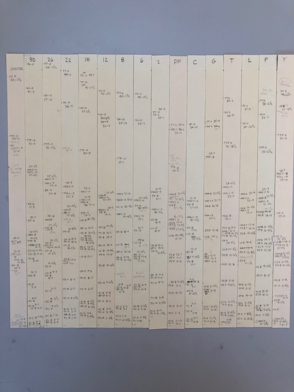
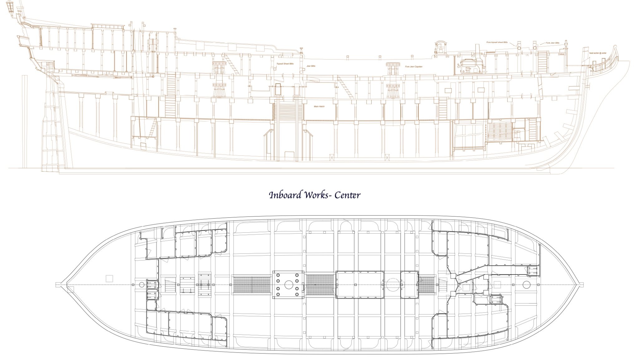
Christian, you really got me thinking as a result of your kind comment and suggestion in July regarding my drawings. Indeed, your comment caused me to spend the last several months redrawing and expanding the set. Why have I backtracked on the drawings, and not kept up with the planking on the actual model, which is now tantalizingly close to completion? I realized that I have invested decades of research into this particular ship. And yet, I have only a number of incomplete and inconsistent drawings to show for it. They were more like notes to myself done just in time for the next part of the build. They had grown incrementally over time, as I learned more and went back to adjust things in areas where I needed. They had become a real jumble of information, sometimes contradictory from deck plan to sheer to body plan. I also realized that I had drawn them decades before I became aware of Steele’s instructions in the 18th century on drawing a ship’s draughts. I realized that my original drawings were pretty rough and ready. Good enough for building the model, but not entirely accurate in their construction. For the sheer, for example, many years ago I had painstakingly measured height of things like wales from the Xerox prints I had obtained from the National Maritime Museum, then plotted these on each station line. I then linked them together with a long flexible ruler. I had no idea at the time that these lines were actually created as arcs of a circle with 3 defined points at the head, midpoint and stern. Mine were close, but not the real thing. In the spirit of creating an accurate record of my research, and enjoying the challenge of recreating the drawings as Thomas Slade would have done, I started a redraw. And then I came to realize just how distorted the original Admiralty prints had become over 250 years. The height of a toptimber in the body plan was as much as several inches off relative to the same height shown in the sheer, and the scale at one end of the sheer was several inches different from the scale at the other end of the same drawing. The scale itself was so fuzzy that measuring against it could be interpreted as much as an inch or two either way. The inboard works drawing was off by half a foot in some places. This didn’t matter for a 3/16” = 1’-0” model, but it mattered a lot when trying to draw the body plan according to the Steele instructions, when a few inches off meant that the geometries in each frame would not line up. So, I had to measure and fudge, until I could get the geometry to align with the measurements off the original prints. I made tick strips of relevant heights from the body plan, then adjusted a little where the sheer showed something different, then tried the geometrical construction; going back and forth until everything lined up. I learned more precisely how the geometries of a frame related to each other: and here is the complete body plan now accurately constructed: From this, I began redrawing the inboard works and sheer. I also decided to draw the orlop and holds including the magazines. I never drew those, because my dockyard framing system omitted the magazines; and everything below the gun deck was a mystery to me. Now I know much more about what was going on down there. These are still works in progress, shown here mainly to let you know that I have not fallen off the face of the earth, or stopped work on the Bellona. I may post some insights I gained while drawing these, about the design and construction of these ships. For example, I finally found an answer to a question I posted several years ago about the quarterdeck beams seeming to raise their roundup as they approached the stern. Now I know what is going on, and I will share in a subsequent post! Best wishes, Mark


-
JR, thank you so much for the information on the aft stool or not. It seems compelling that the stool was in use by the time of the Bellona in 1760. The only remaining question is that the rig at this time, as best I can understand it, had only a topmast with a pole on the mizen, no topgallant mast. So there would not be a backstay for the absent topgallant, only a backstay for the topmast. So there would be only one line rigged to the stool. Maybe that the way it was. Or, maybe there was a backstay on the topmast pole running to the stool? Any guidance here would be much appreciated. Best wishes, Mark
-
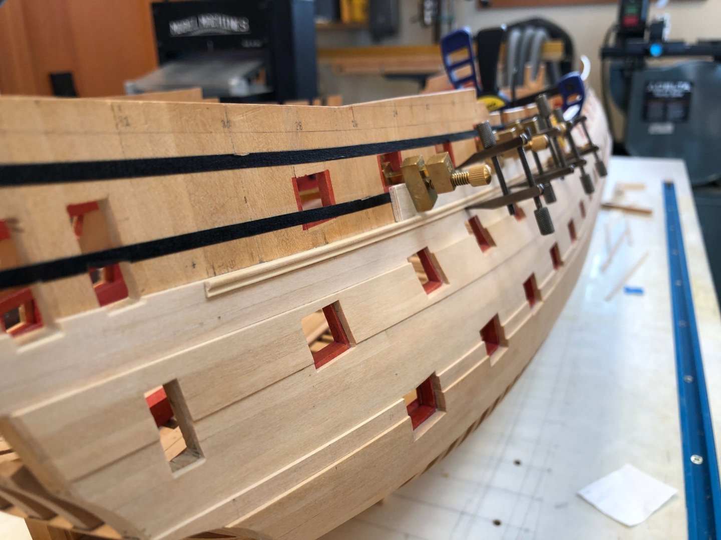
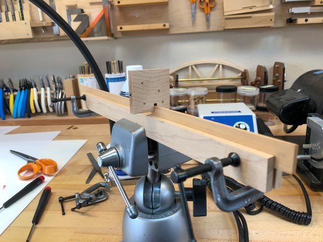
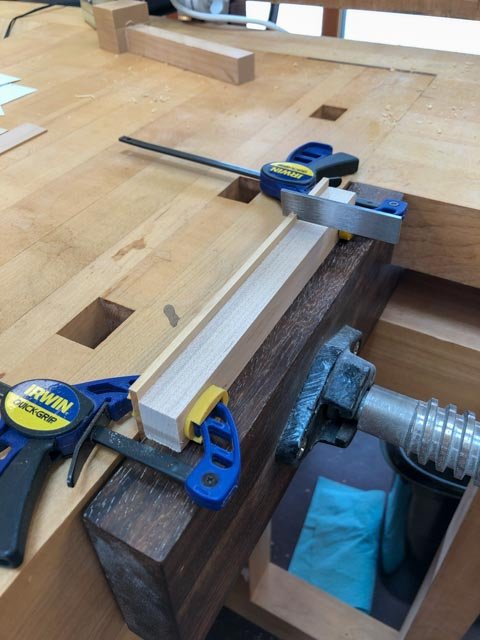
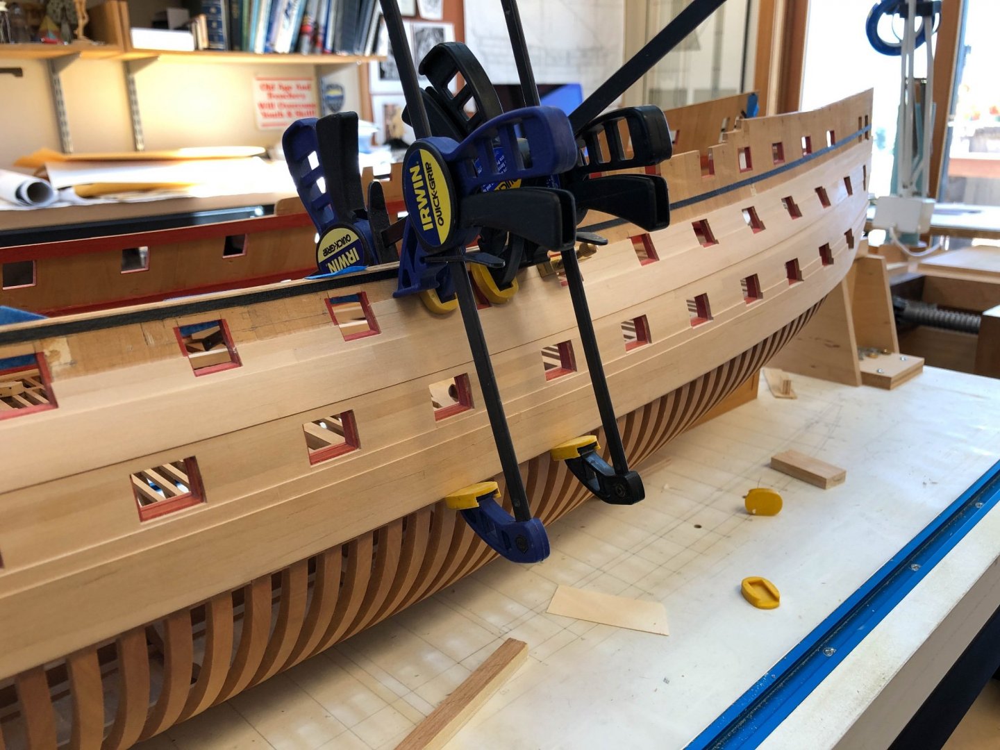
Hi druxey, for some reason, maybe having to do with the grain or the stiffness of the wood, or poor hand coordination, I could not keep the cutter at a consistent angle to the table top. So the top edge wavered too much. Mounting the cutter in a handle at least keeps the angle constant for me. Still much to learn! At last, I was able to start putting the waist moulding in place. I tried drilling holes for pins to keep things in place, but it was too sloppy to force the gradual curve and keep it there while the glue dried. So I made some battens that ride on the top of the planking edge underneath the moulding, clamping them to the ship side. Then it was a simple matter of clamping the moulding vertically to the batten. It is making a perfect, sweet, curve.

-
here is a link to the instructions: https://www.sherline.com/product/3200-indexing-attachment/#instructions Mark
-
Thanks so much, Marc, it is a good thing I am not doing this for a living! I wish I could think that everything I have learned will be applied to another model, but at the rate I am going, this is pretty much going to be it!
-
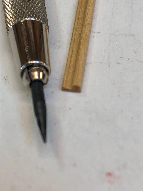
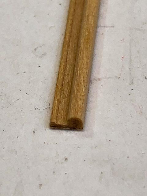
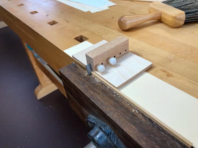
Much fun figuring out how to get decent mouldings! But I finally figured it out. First round: I used an old exacto knife blade, shaped with a grinding wheel in the lathe. At this point, I was still trying to cut the blank at the angle of the tumblehome. I mounted it in a holder: I expected the handle riding against a fence to stop at the right depth: But this failed miserably. For some reason, the depth was not controlled at all, and the top edge waved up and down. And the cutter did not define the outer edges, just the face; so the moulding top curves did not gracefully flow into the sides of the profile; there was always a little ridge or the curve got cut off. Next idea. I made a new cutter, now abandoning the idea of cutting the moulding at the angle of the tumblehome. It was too complicated, and at this scale did not show at all. So now I tried a simpler profile, straight up and down, and I provided sides to the profile that would run against the blank so the curves would flow evenly down into the edge of the blank. The edges of these sides were softened with a file so they would not cut, only guide. I cut the profile in a Lie-Nielsen A2 steel blank (for his moulding plane; https://www.lie-nielsen.com/products/beading-tool-blade-blanks, 5 for $10). This made a fantastic cutter. I was able to shape it partly with ball end mills in the milling machine, and partly with files. And its greater thickness greatly reduced chatter. Lie-Nielsen claims it does not have to be hardened, and I will see if it starts to dull or not before I am done with this shape. At first, I tried just running the cutter along the edge of the blank, counting on a fence to stop the cut at the right depth: This did not work well at all. The upper edge was amazingly wavy. Perhaps the more powerful cutter grabbed at grain more aggressively. So the final idea, which works perfectly, was to build a holder for the cutter, angling the cutter at 15 degrees, and with a fence riding against the side. The workbench top now acts as a stop. I put a number of slips of manila folder and typing paper between the cutter and the workbench top to lift the cutter up so it just takes a whisper of a cut. When it cuts no more, I take away a slip of paper from underneath, dropping the cutter down slightly, and cut again. I do this repeatedly until the full profile is cut. You can see below the sweet curl of a cut coming off the cutter. The exacto blade cutter only shaved off sawdust. I then cut the blank to the right thickness, keeping a piece of typing paper against the fence. In my earlier efforts, the metal of the fence was discoloring the moulding; the paper keeps it clean. And voila, perfect mouldings: This turned out to be much more difficult to control than I had originally expected, but a lot of experimentation and I got there.
-
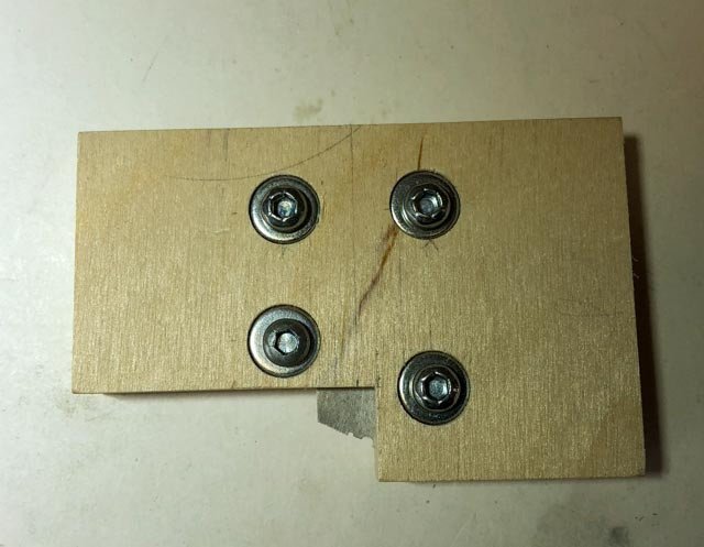
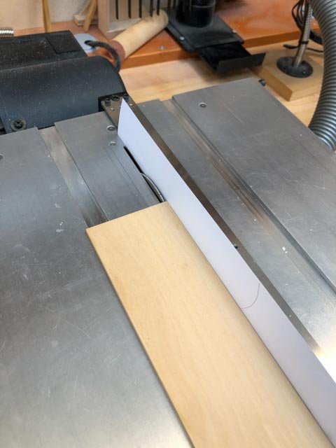
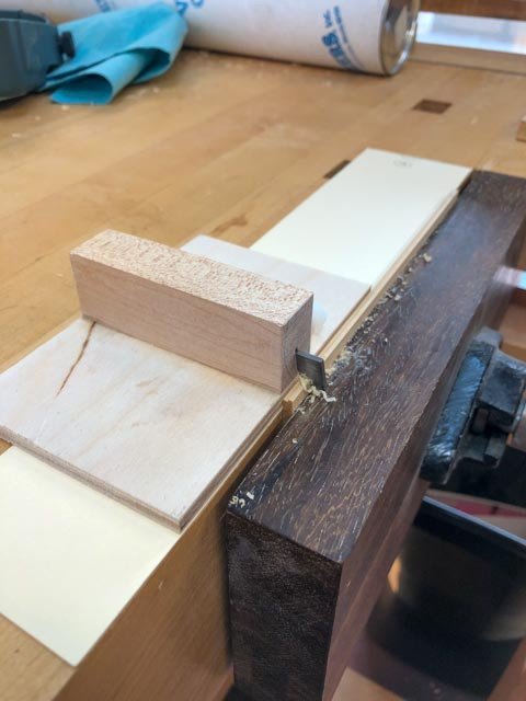
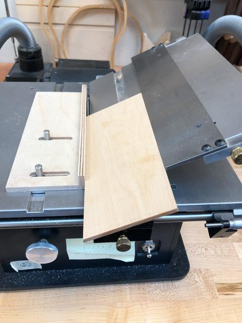
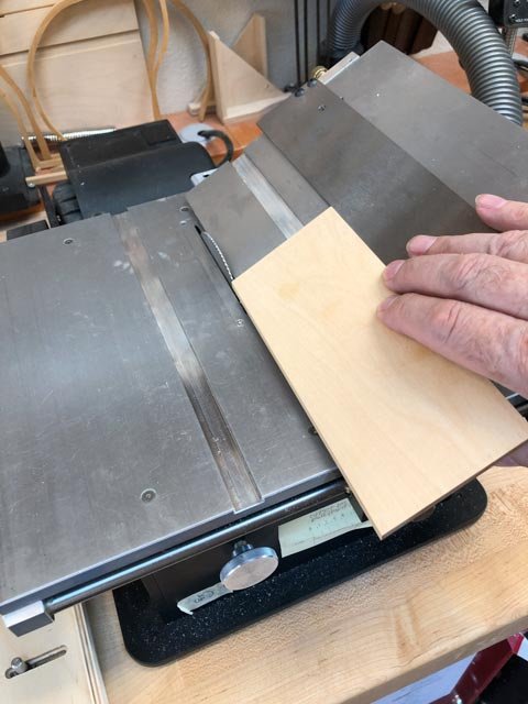
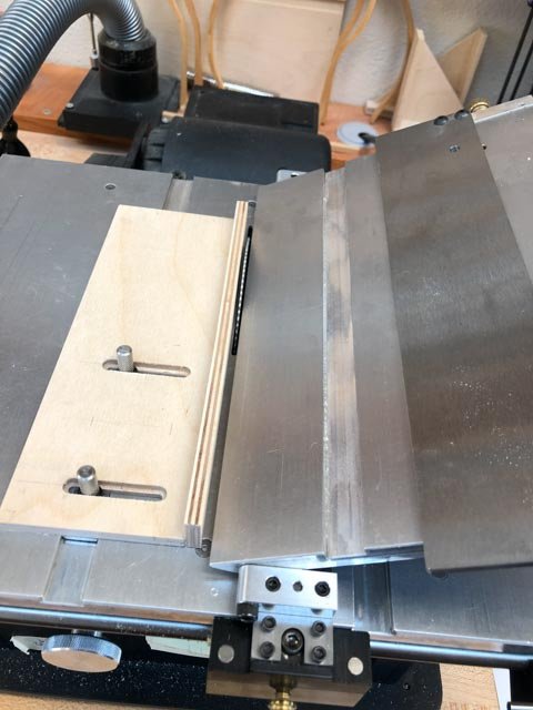
Thanks, Ed, it has been a pretty long apprenticeship! I started working on mass producing the waist mouldings. In my first experiments, I scraped the moulding on the edge of a wide blank, then cut off the moulding at its appropriate width. I have to use the angle table on the Byrnes saw, since my moulding is angled for the extreme tumblehome. This turned out to be exceedingly fussy, resetting the fence for each new cutoff, and aiming for a tight tolerance to keep them all the same thickness. I decided to try another idea, which is to cut the blanks to the right thickness, and then use the scraper with a depth stop to avoid cutting beyond the correct thickness of the final moulding. The first step is to produce a number of parallelogram blanks of exactly the same thickness, on the tilting table. So, I built a jig. It lets me slide an auxiliary fence up to the saw blade, with a spacer of the appropriate size to offset the auxiliary fence from the blade: I then slide the blank with its angled edge already cut up to the auxiliary fence. This allows me to slide the tilting table fence down to the blank, thus setting the fence for that particular blank at the exact distance needed beyond the saw blade: And then I remove the auxiliary fence, and cut holding the blank firmly against the tilting table fence: Only a day's worth of thinking and building. This is why this project is taking so long!🙃 Mark
-
Thanks so much for your comments, druxey and Ed. druxey, good idea about pre-drilling the mouldings. The trunnels will be noticeable when finished, and predrilling can keep them all in a constant position up and down. It is a small target for the drill in the concave part of the moulding, so using a fence on a small drill press can keep me in the safe zone. I have been concerned about how stiff the moulding is, and how it is not easily forming the sheer curve without something to pull it up to. But I discovered last night that my test piece was cut too thick. I am thinning it down today to the correct thickness, and hopefully it will become a little more pliant. Ed, I regularly look to your books on the Naiad for advice on construction methods; you provide a great road map for the these specific kinds of details. Along with David Antscherl's Fully Framed Model books, I have some great published guides in my shipbuilding apprenticeship! Best wishes, Mark
-
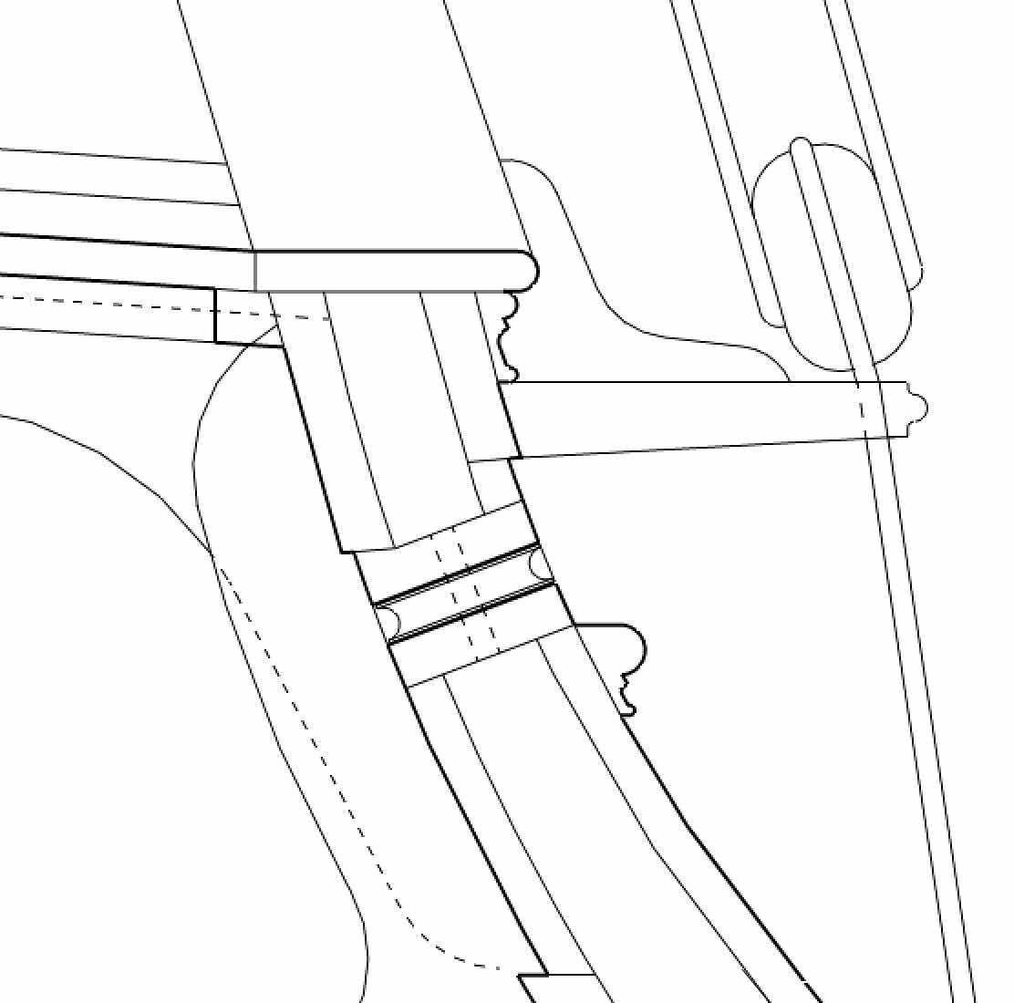
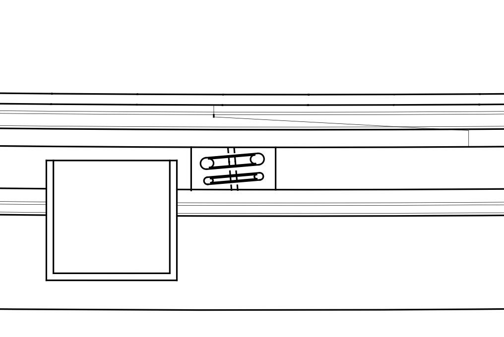
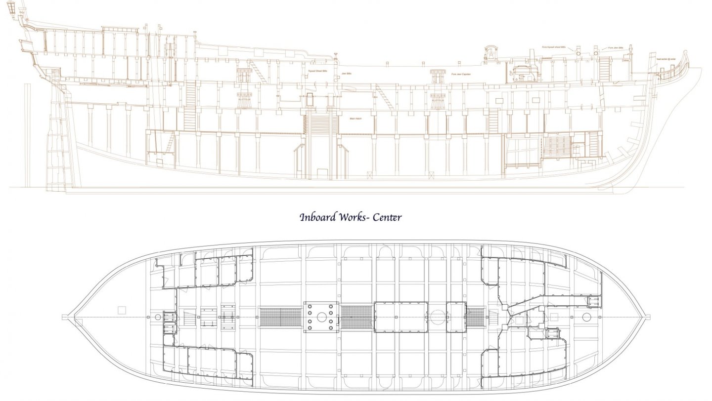
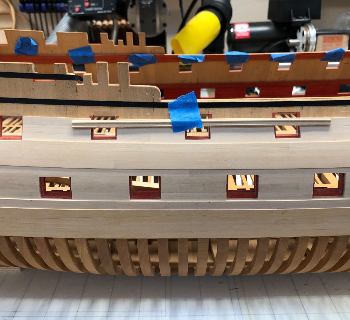
Thanks so much, Siggi, I have been away from the shop for a long while, and only today saw your posting. I seem to recall that you did put the stools on your model of the Dragon. It looks like it was a detail that changed back and forth, so either way would be correct. I will follow the image you included of the Dragon, showing a stool. It is more consistent with the rest of the ship! I have been taken away from the shop for a good period of time, only able on occasion to install more planking. I have just about finished up to the waist rail, needing only the strakes at the bow which bend outward to support the cathead. It was a fairly simple matter of spiling to the plank below, trimming for ports, and measuring the widths in the normal way using a planking fan. Slow but steady! This then brings me to the fun part, installing the waist moulding. I have taped a sample to the side to see how it will look, and how I will install it. I read in Ed Tosti's Naiad book that the moulding should be installed in long lengths, then cut away for ports later, to ensure a smooth curve along the sheer. This makes sense to me. I am thinking about clamping a former along the upper edge of the planking, then pushing the moulding up to the former and drilling for pins. The pins will later be used to align the moulding as it is glued. I still need to think how I can clamp this against the hull, without damaging the very delicate moulding. In preparation for this, I also had to look again at the sheaves in the sides for the fore sheet and spritsail sheet, the main tack and the main sheet. Brian Lavery's book on the Bellona showed the first three as separate blocks in the sides at the waist. But I was unable to find other examples of that in the period, and Lees' book on Rigging says the fore and spritsail sheets were combined in one block at the middle of the waist during this period. So, I followed this, as seen below. The main sheet is to the far left in the drawing, and the main tack is just under the fore channels to the right of center. I also puzzled over how these blocks fit the sides. Every image I could find of ships in the period show the forward most blocks above the waist moulding, not cutting into it. But when I drew this with the blocks horizontal to the waterline, they cut into the clamps inboard. I did not think this would have been done, given the structural importance of the clamp at the waist. Then I noticed in the John McKay book on the HMS Victory that the blocks were perpendicular to the sides, not horizontal. So I drew it this way, and the blocks clear the inboard clamp very nicely. This is how it looks: All for now! Best wishes, Mark

-
Marc, Beautiful work. I am super impressed by your piercing work. Much to learn from this for all of us! Mark
- 2,695 replies
-
- 3
-

-
- heller
- soleil royal
- (and 9 more)
-
HI Siggi, I have been away for a while, just saw your postings on the frieze. Beautiful painting! I am starting to look at the frieze for the Bellona, and they are quite complex paintings. I suppose on the actual hulls they used large house painting brushes! Mark
-
Marc, I have been out of touch lately, just catching up. Nice line of reasoning on the color question. I look forward to hearing if you find some other hints or leads on this! Mark
- 2,695 replies
-
- 4
-
-
- heller
- soleil royal
- (and 9 more)
-
Hi Don, Others may know better, but I believe the Bellona model with the canted frames on the starboard side probably was not copied much, or even followed on the Bellona itself, because the crooked wood was becoming increasingly scarce and expensive by the mid 18th century. I know how it is to decide which evidence to follow when trying to reconstruct an old ship. I decided that the port locations, if drawn, as are accurate a bit of information as you going to get, and so other things are going to have to adjust to make this possible. Having said that, my original admiralty drawing of the Bellona shows the upper ports towards the stern with three different locations dotted in; they were clearly trying to reconcile the conflicting needs of the internal arrangements, the desire to avoid cutting frames, and so on. No one perfect solution. One idea I have seen in contemporary models is that the frames get thinner fore and aft, or the upper futtocks or top timbers are offset a little on the lower part of the frame, to avoid ports. Since you already made the decision to keep the frames a constant width fore and aft all the way to the top, this option is not available to you any more. If your framing will be covered by planking, you might just let the cut frames disappear into their plank coverings, and no one will be the wiser! Mark
-
Hi Allan, Sorry for the delay; just got back from a trip to Denver for a wedding... So it sounds like printing on the permalite 20 pound bond was the best bet. I am guessing you did not stretch it like watercolor paper in the first place, since you were printing on an ink jet printer; did the paper wrinkle when you glued it onto the wood? What kind of glue did you use? I am also impressed with your TurboCad skills in drawing forms like this! Best wishes, Mark
-
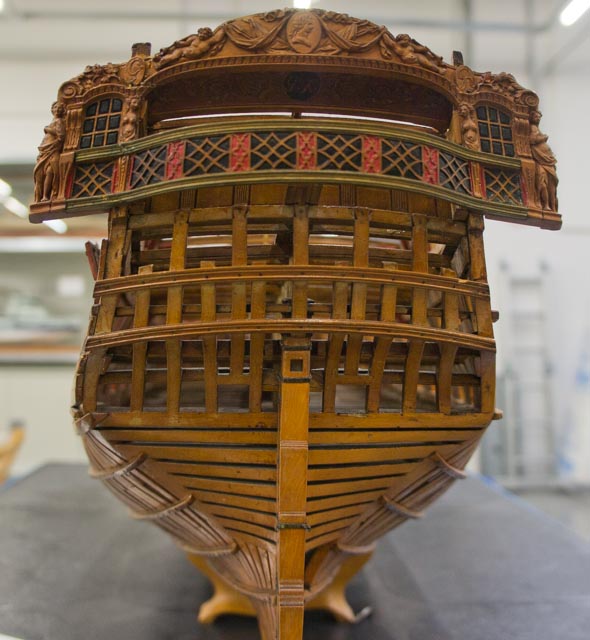
The first model of the Bellona (ca. 1760) shows a proposal on the starboard side to keep the upper frames as continuous as possible to the top. The port side shows the more conventional framing. Mark
-
Allan, Will you post the outcome of your experiment? I am very interested to see an archival way forward on this fascinating topic! Mark
-
To add to Allan's question, would it make sense to paste the paper frieze onto the hull BEFORE attaching the mouldings above and below, so there can be a slight overlap of the moulding over the paper, keeping a clean line between the two? Mark