SJSoane
-
Posts
1,648 -
Joined
-
Last visited
Content Type
Profiles
Forums
Gallery
Events
Everything posted by SJSoane
-
 Alex, I agree with Gary, it looks perfect! Mark
 -
I forgot to mention in the last post that this question about the mizen backstay is a good example of a challenge I have faced working on this project, where I look for examples in other models or drawings to answer a question. I have a great tendency to see only what I expect to see. And if an example is contrary to what I expect to see, I tend to think that there must be a mistake or an omission in the model or drawing. In this case, I really expected this to be a stool. And when I could not find one of the right period with a stool, I assumed that the model builder or draughtsman just "left that detail off". That is why it is so great to have many eyes in this website, each bringing a different way of looking at things! thanks again. Mark
-
Hi Alex, Mark and druxey, Thanks so much for you thoughts on this. Alex, I think you found the key to the puzzle. I am assuming the Medway at 1742 also had a mizen with only a topmast, not a topgallant. So it, too, would have only one backstay at the mizen. Unless someone knows of another piece of rigging at the mizen with deadeyes in this location, I will assume what we see in the Medway is the backstay to the mizen topmast. It appears to bolt directly to the side, perhaps this is what Lees was calling a deadeye plate as one of the possible rigging arrangements at the mizen topmast backstay. I think, problem solved. thanks! Mark

-
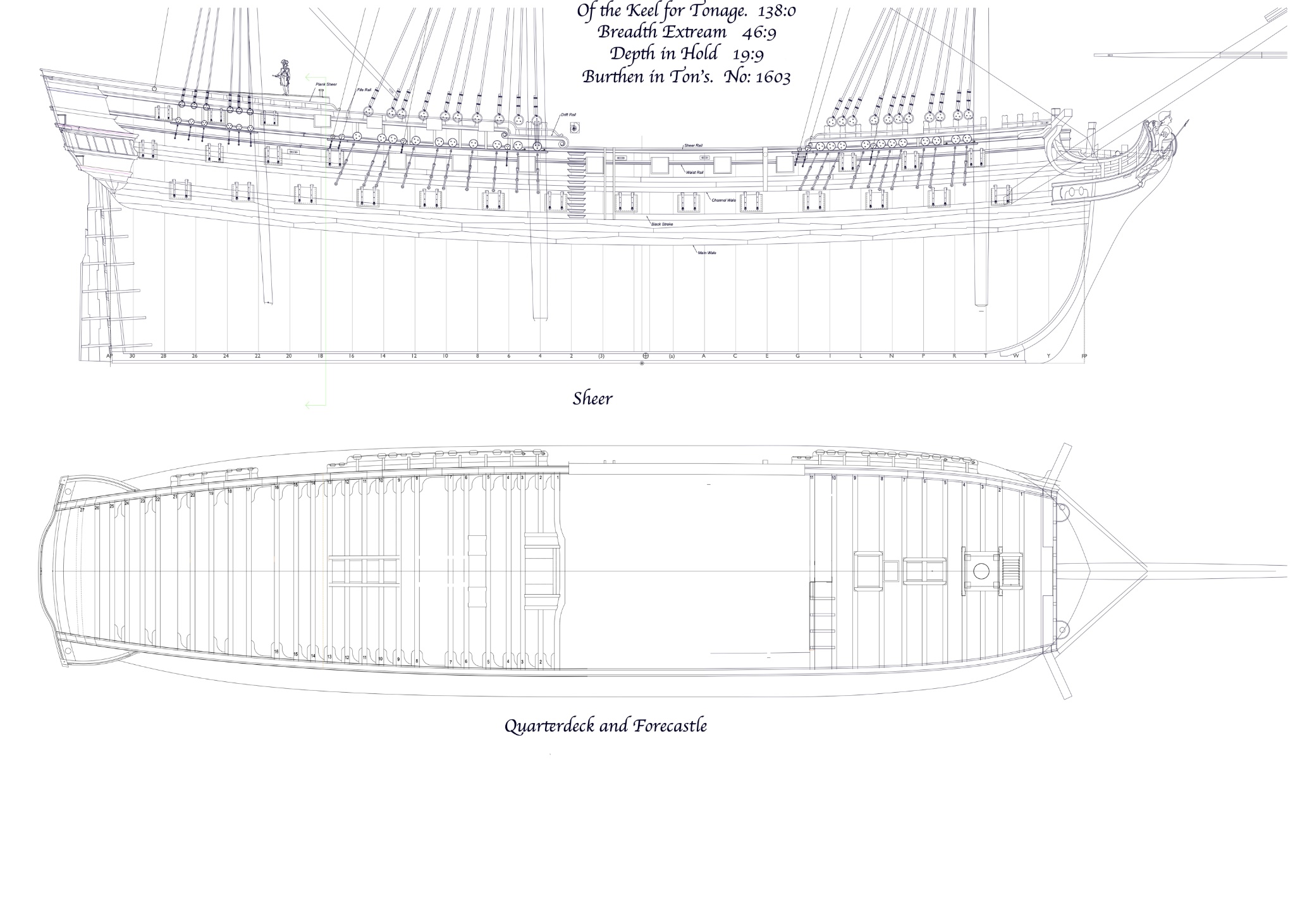
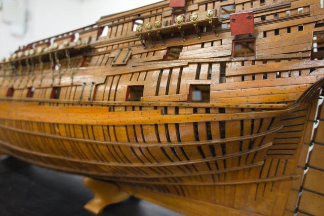
Hi druxey, My copies of the original 1759 Bellona draughts show the same thing as the model of about the same date; 3 and 3, no stool. I confirmed that the ports were moved at the stern in the later 1780ish model, leading to a different arrangement of 4 + 2 deadeyes to avoid a port. But no stool or other backstay support in either model. A mystery.... Mark
-
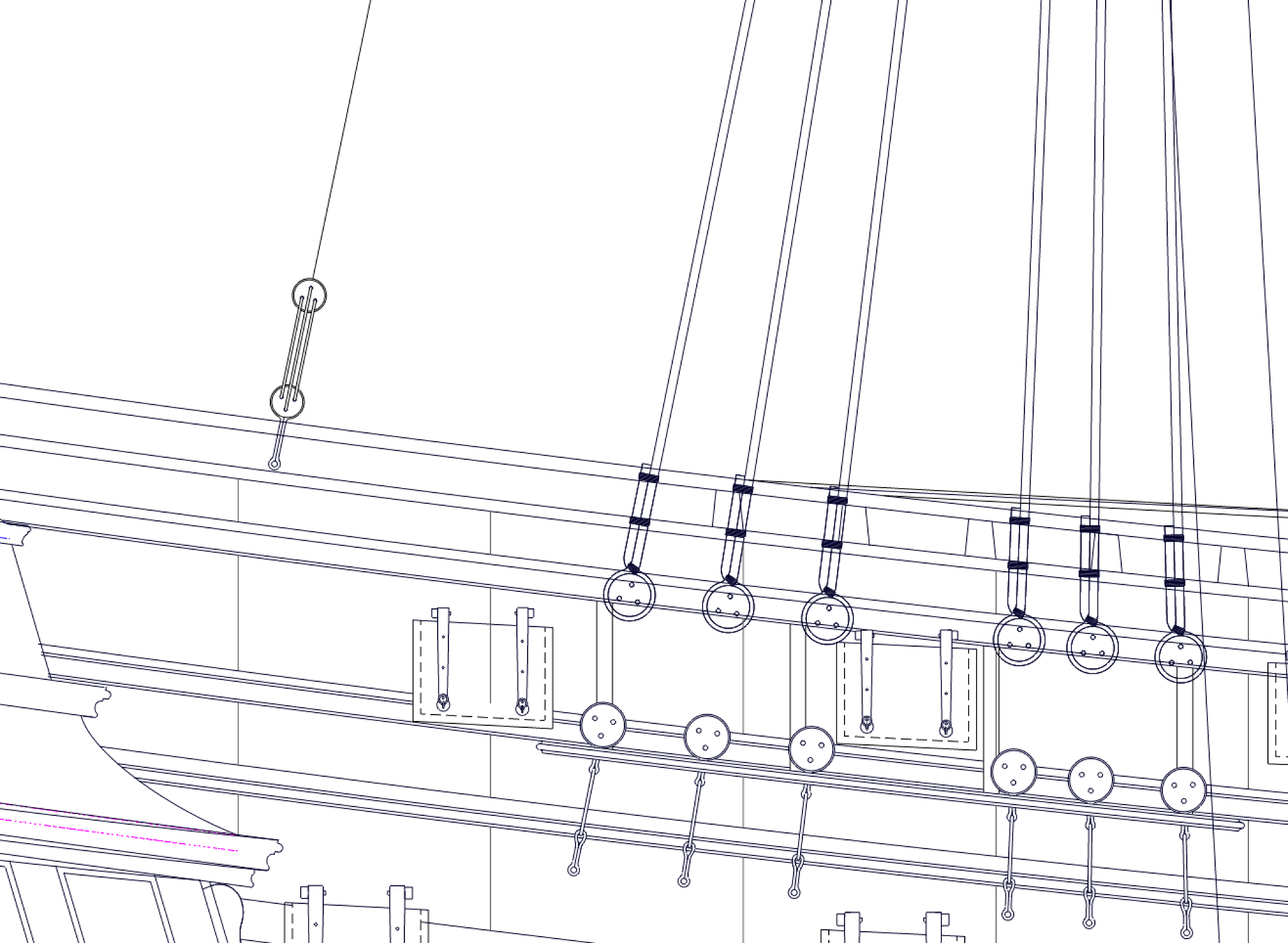
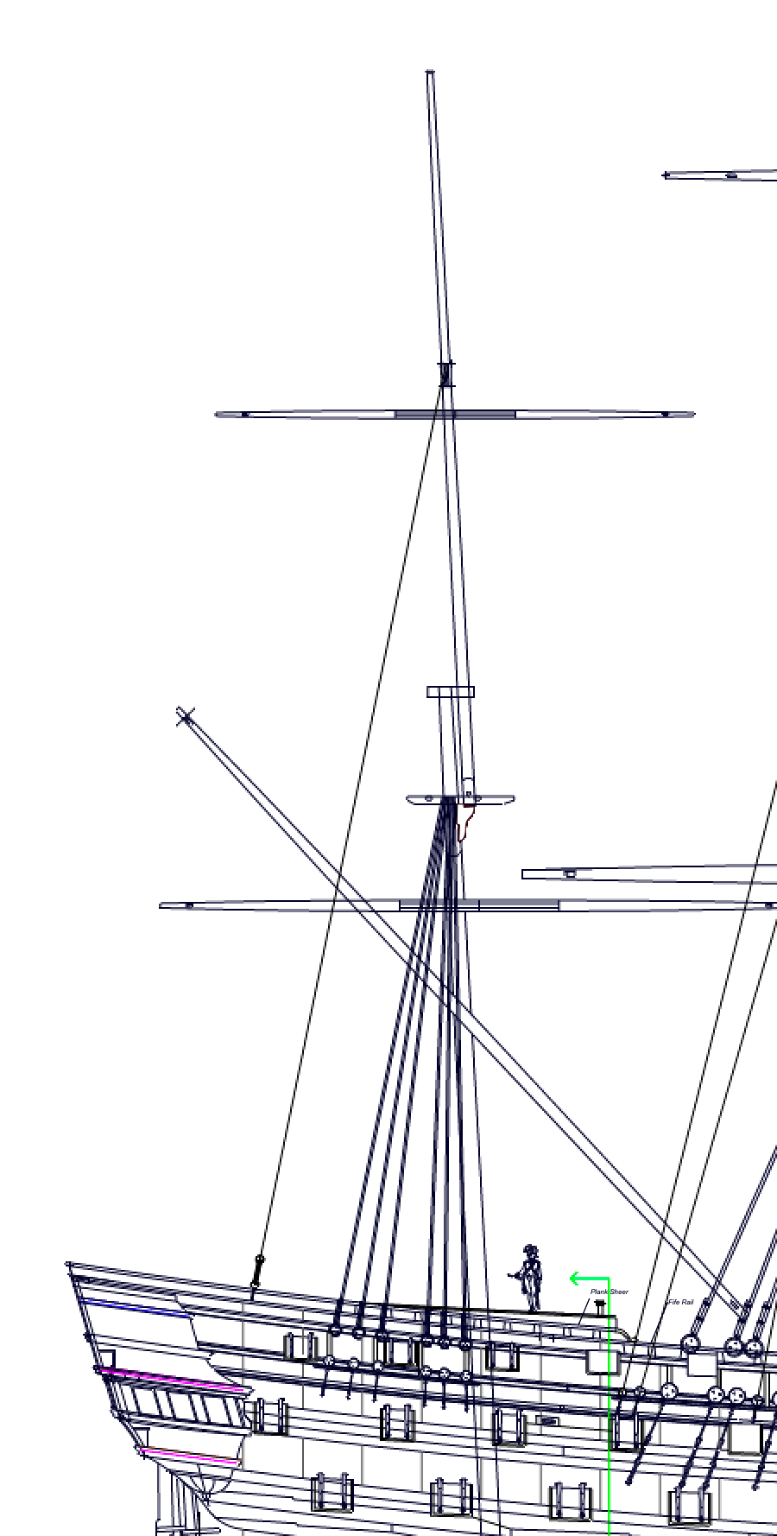
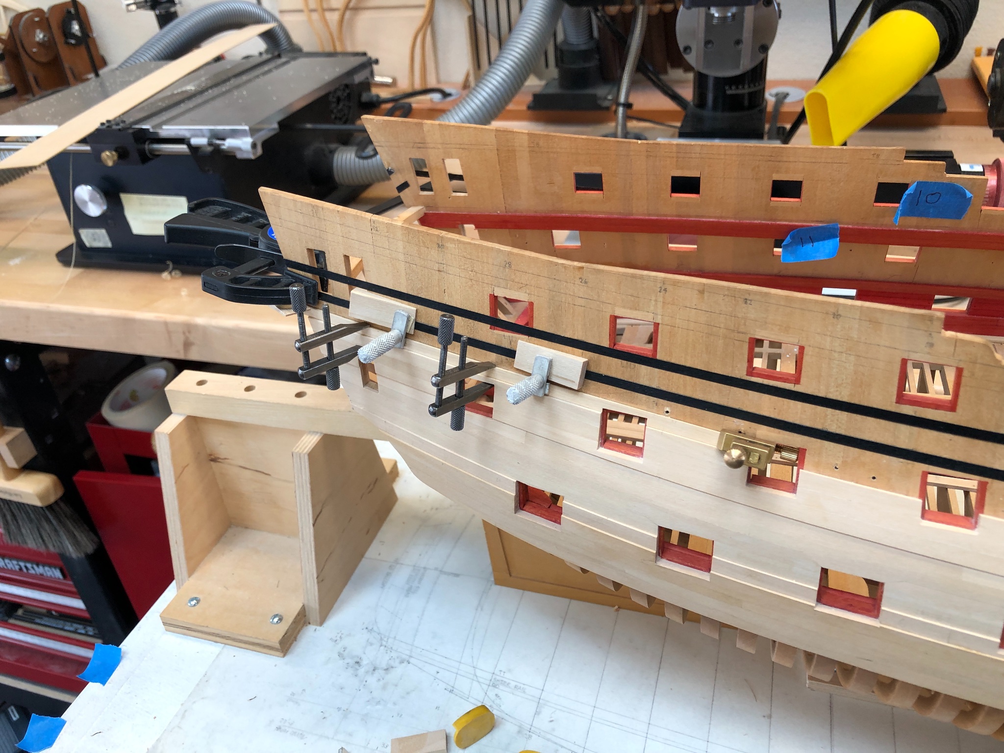
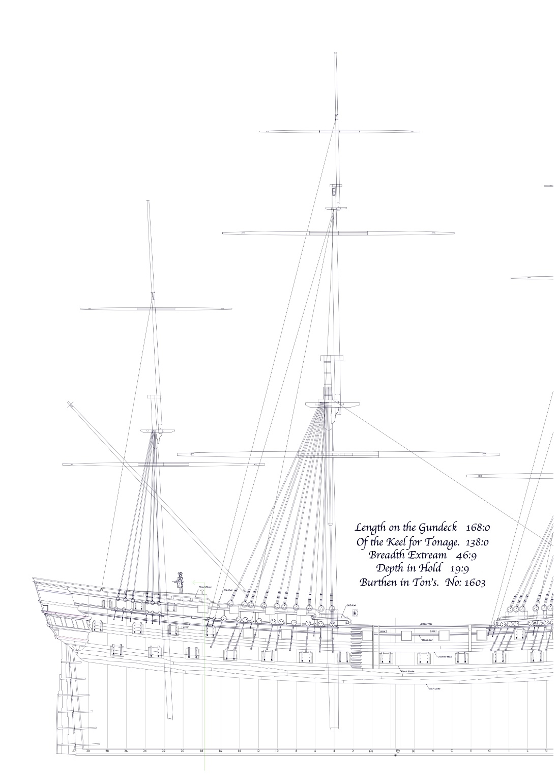
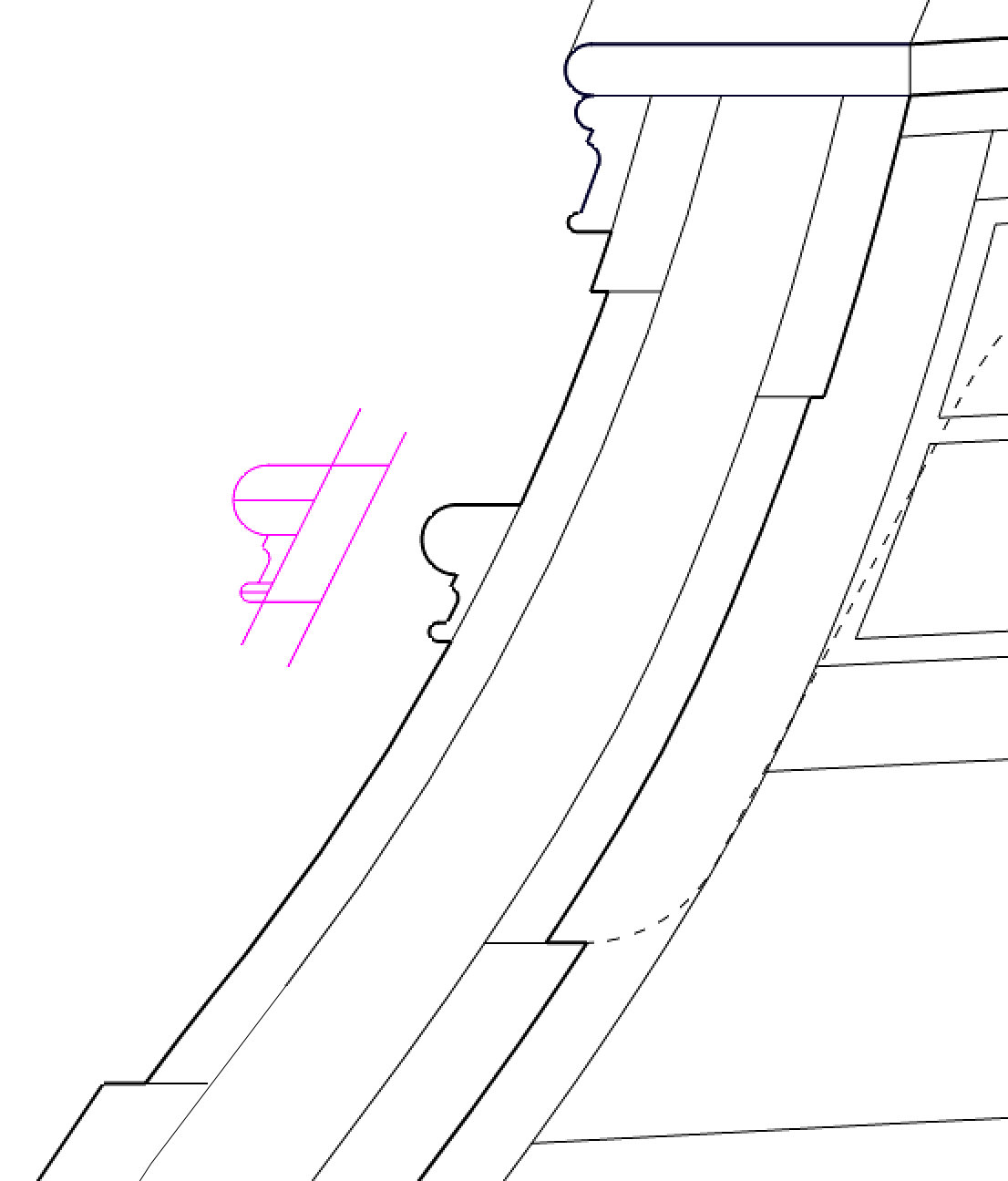
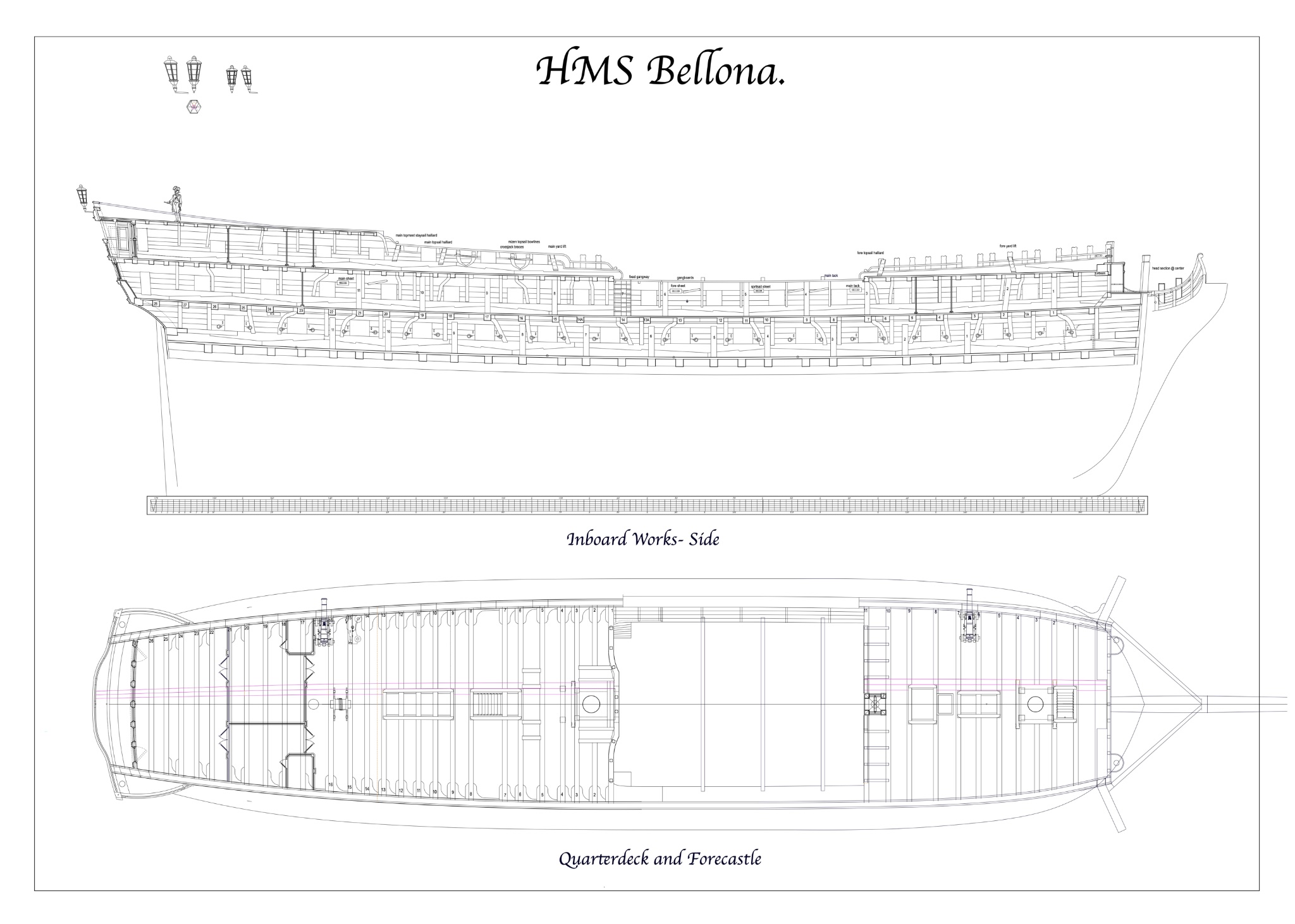
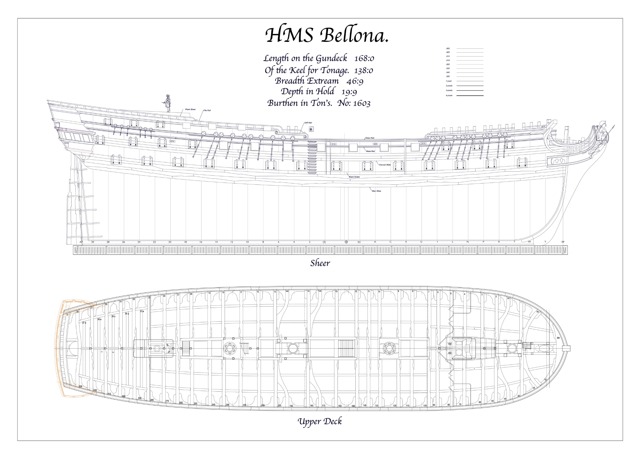
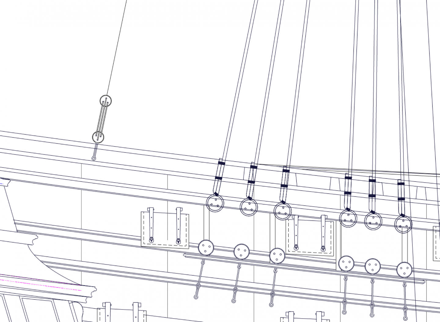
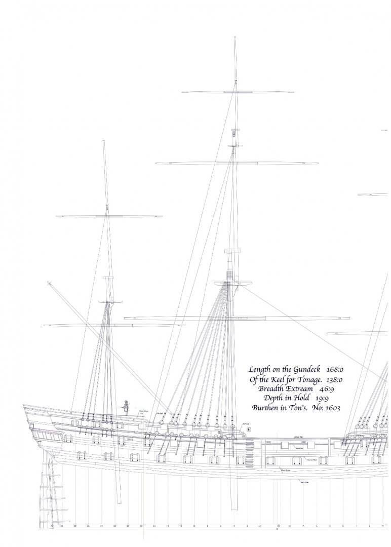
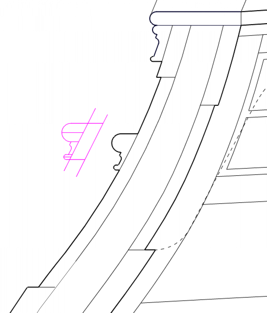
Thanks, druxey, doing the moulding afterwards sure simplifies the next steps of planking! Got the first plank on above the channel wale today. Gets me back into the groove. While waiting for the glue to dry, I started looking forward to outboard fixtures and fittings. I drew up the channels, and discovered a few questions. First, as best I can tell, the mizen in this period did not have a topgallant, only a topmast with a pole (see below). So this means that there would only be a backstay to the top of the topmast, correct? And no backstay to a non-existent topgallant. So am I correct in thinking that there is only one backstay coming down to the sides near the mizen channel? The Bellona drawings do not show a deadeye for a backstay on the mizen channels, nor a stool for backstays. I could invent a stool, but it would have only one deadeye, for the mizen topmast backstay. Lees' Masting and Rigging mentions mizen topmast backstays on page 58, and says they either come down to a stool or to a deadeye plate. Might it be a deadeye plate because the drawings do not show a stool? Second, I see in David Antscherl's Fully Framed model books that there are two rings in eyebolts on each of the fore and main channels. Brian Lavery's Bellona books shows a fore breast backstay on the fore channel, a line seized to the channel, through a block on the backstay, and back down to another seizing on the channel. Would the rings and eyebolts be the fastenings for the breast backstays? Mark

-
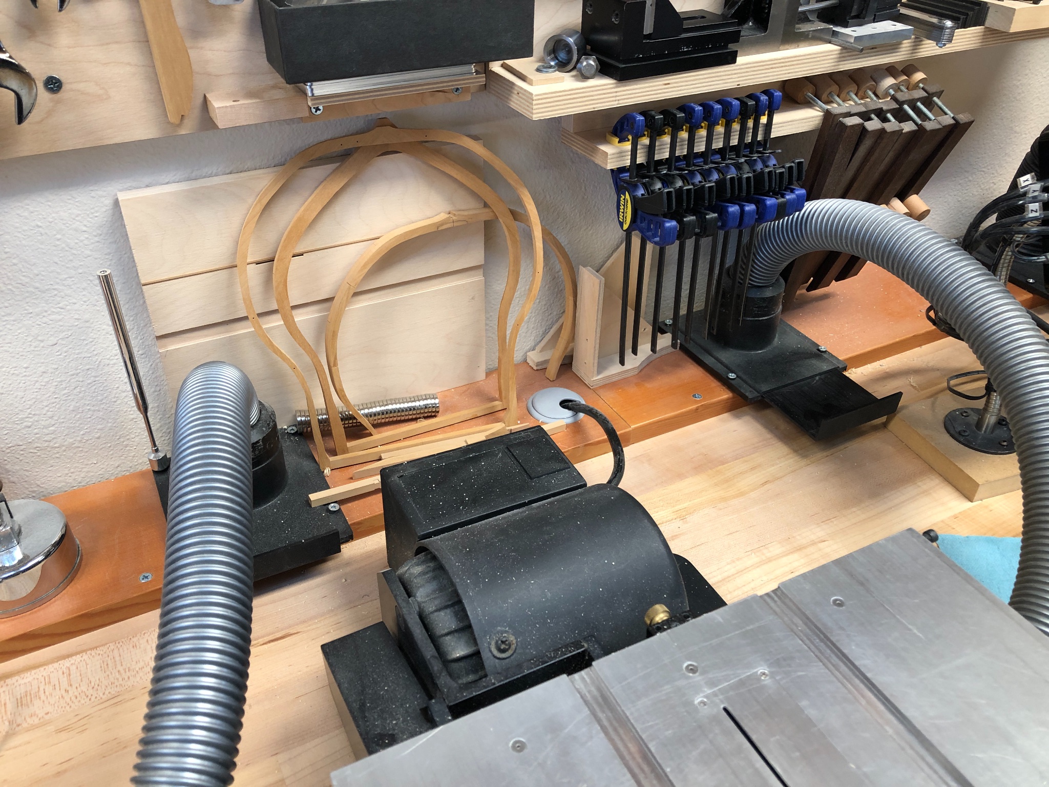
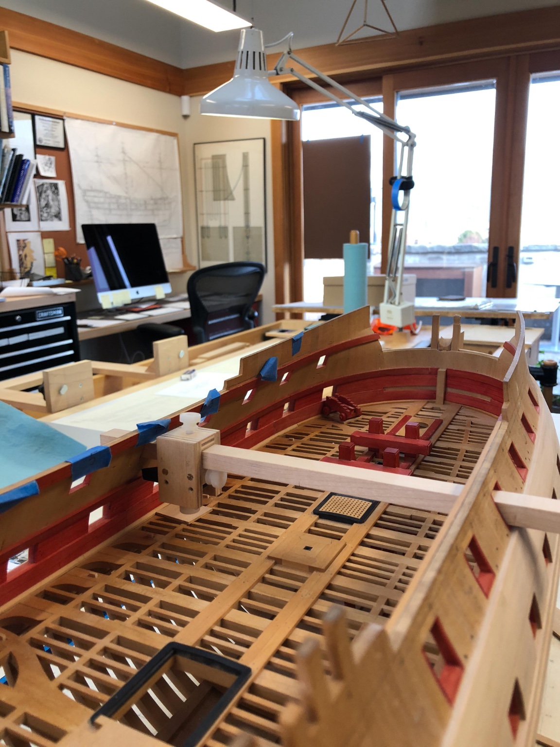
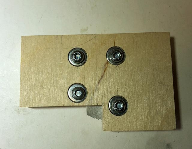
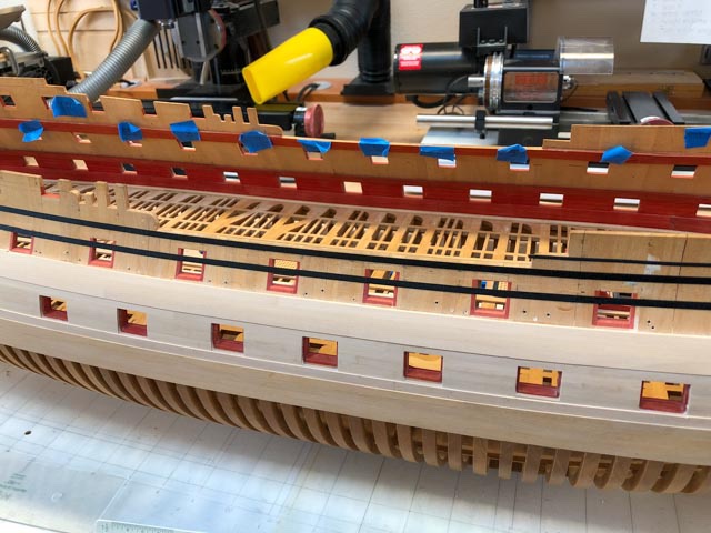
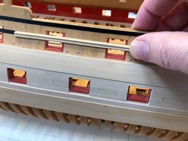
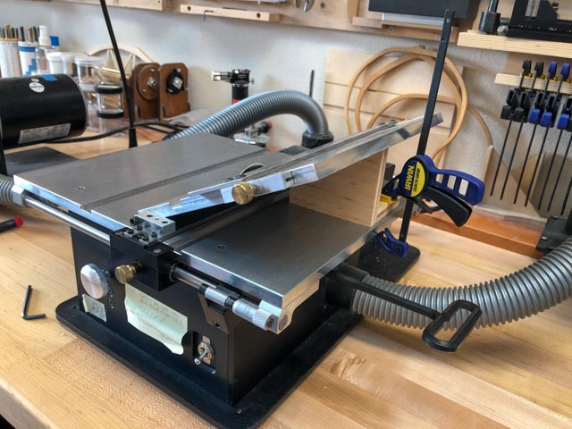
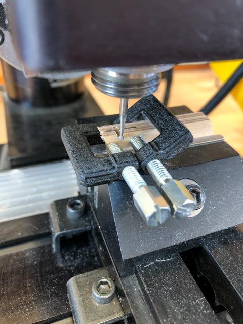
Hi everyone, I have been in and out of the shop for the last long while, attending to other life things, but also really pondering my next steps forward. After thinking at great length about the issue of when and how to mount the guns, I finally decided that it would be best first to finish all of the outboard work, allowing me to turn the hull on its side for painting, putting in the friezes, etc., then go back to working on internal work including the decks and mounting the guns. So I have turned my attention to planking again, now facing the fun prospect of making the various mouldings on the upper works. I started looking at how to make the waist rail, to start. It sits against a large tumblehome, so its profile had to be cut at an acute angle to keep the upper surface level. I used an old hacksaw blade softened with heat, and then tried cutting the profile a couple of different ways. I first tried hand filing, and then for fun I tried milling the profile, sandwiching the metal between two thin pieces of plywood to keep it from flexing as the cutter ball passed by: I ended up with a combination of hand filing and milling, putting the final shape into an "L" shaped wooden holder creating a fence. Early experiments with letting the cutter run freely without a fence did not work well. It wandered too much. Because the moulding sits on the angled tumblehome, I decided to pre-angle the moulding blanks by running them through the Byrnes saw using the angled table. I found this to be difficult to set and keep the desired angle, relying solely on tight Allen screws at the mounting. So I made a wooden angle block, clamped under the table. It allows precise setting, and I can return to the exact same angle later on. I first tried scraping in my small bench vice, trapping the moulding blank between two long vice faces. but this allowed too much vibration, leading to uneven cuts. I later tried clamping it in my large bench vice, which proved much more stable. I neglected to take a photo of this better arrangement; maybe next time. With more confidence in my ability to make good mouldings, I turned to thinking about the remaining planking. I ran 1/8" wide artist's tape (9" to scale, the exact size of the desired mouldings) at points measured from the sheer drawing. This allowed me to confirm the fairness of the runs, especially relative to each other. I did discover that the hollow at the flair out at the bow at the starboard side was a little too hollow, leading to a slight, undesirable reverse curve on the waist moulding. When I faired this area almost 20 years ago, I did not fully appreciate the direction of the run of the planking itself. So don't tell anyone, but I have had to glue a small filler piece into the hollow, to fair it out to match the port side and clean up the run of the waist moulding. It was only off by less than 1/16", but enough to cause a hollow. All will be covered by the planking! This all brings me to a big question for those of you who have experience with laying mouldings. I had originally planned to glue the mouldings directly to the frame, butting against it the planking above and below. This, I thought, would allow me to lay the mouldings on a nice curve because I could clamp it down to the faired edge of the planking below. But as I pondered how the mouldings would intersect things like channels, fenders, chesstrees, the various mouldings at the head, and how they would stop at the quarter galleries astern, I began to think it might be easier to apply the mouldings over the planking. But then, how do I keep the mouldings precisely faired and parallel to the planking underneath it? My wood is quite stiff, and does not nicely bend to a smooth curve by itself. Maybe, a wide batten that could rest on the upper edge of the channel wale, with a faired upper edge, and to which the moulding could be clamped in a vertical direction as well as against the hull? All for now, Mark
-
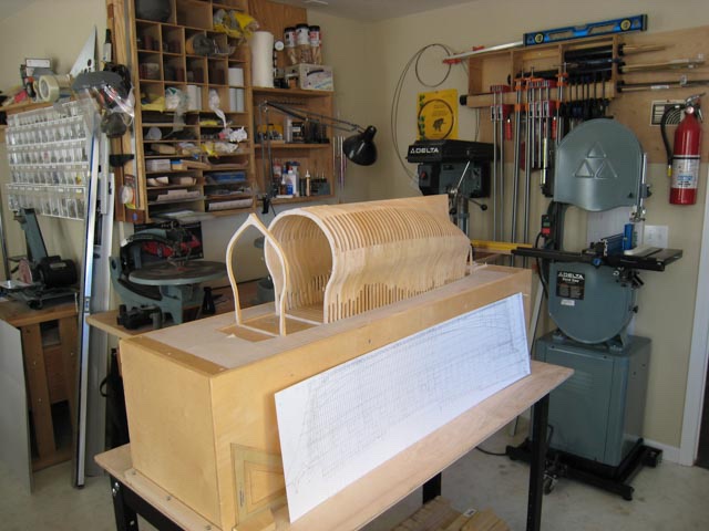
I agree with the cumulative measuring idea. One way is to measure from a set point out to every frame. Another way is to draw the frames on a jig at the base of the hull (see below). Either way, every time you place a frame, measure where its face ought to be. If the frame needs thinning down, sand the face on sandpaper glued to a sheet of plywood. That keeps it flat, and you can use calipers to check the thickness of each edge to ensure the two faces are parallel. In my project below, the frames turned out to be varying thicknesses to keep the whole thing the right length as I added to the hull, but the differences are so slight that you never see the discrepancies. Another subtle opportunity here. In my case, I set a square against the face of the frame. If it was slightly out of square to the base vertically, I used the sandpaper on plywood to gently adjust top or bottom to get everything back into square. Mark
-
Alan, I regret buying my plastic full size kayak. Building your's full size would have been much more satisfying! Mark
-
Gaetan, your shop should be on a Nautical Research Guild tour some day! Mark
-
Hi Alan, Doing more drawing is how I procrastinate on actually cutting wood! It is becoming a bad habit...🙃 Mark
-
Gary, Nice to be reminded of your outstanding framing. It is fun to start covering all of this up with planking, etc., but it sure is nice every once in a while to see a hull in full frame in the earlier stages of a build! Mark
-
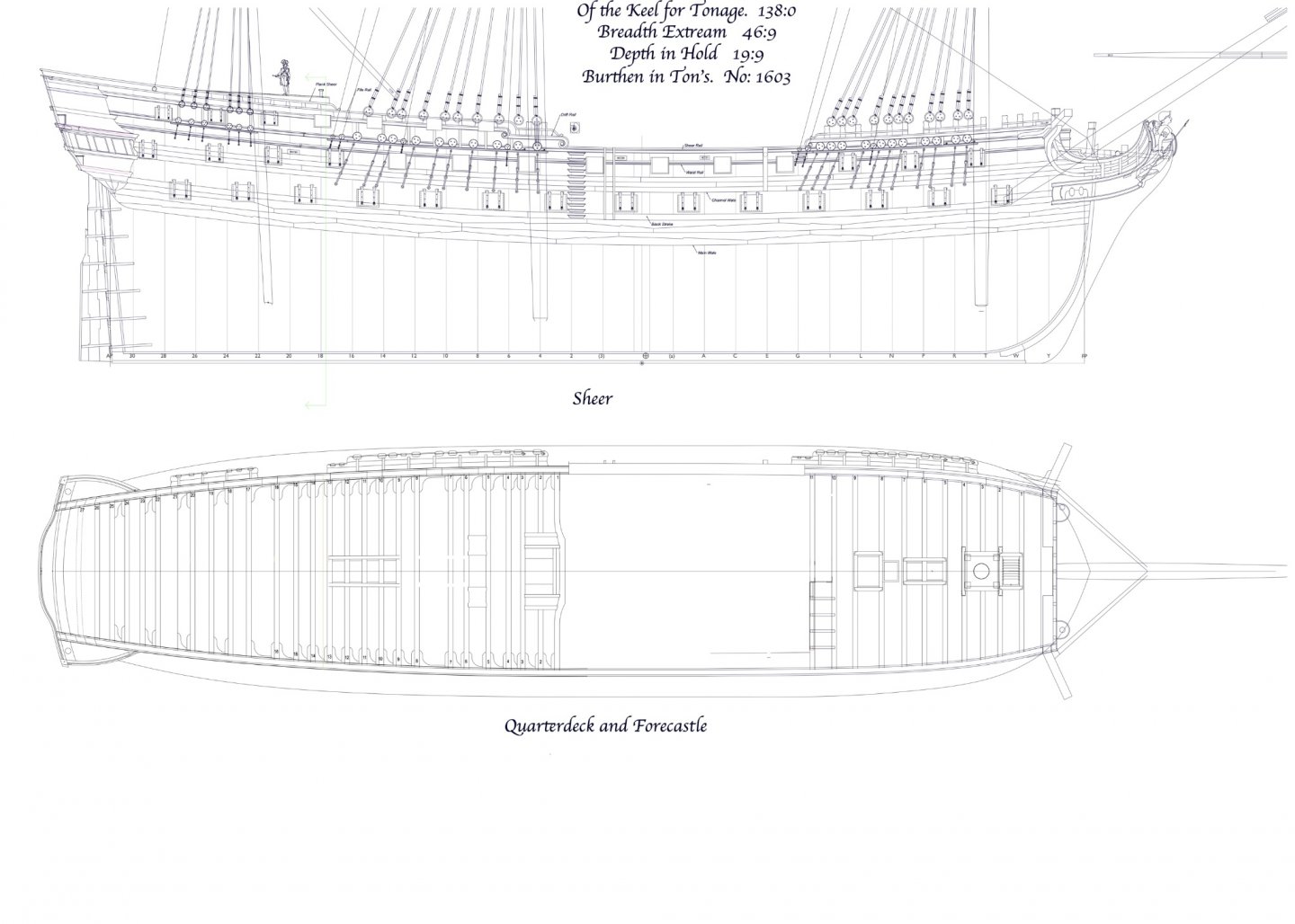
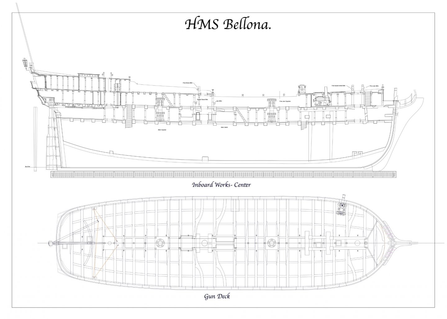
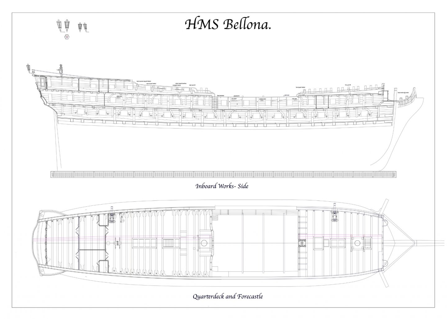
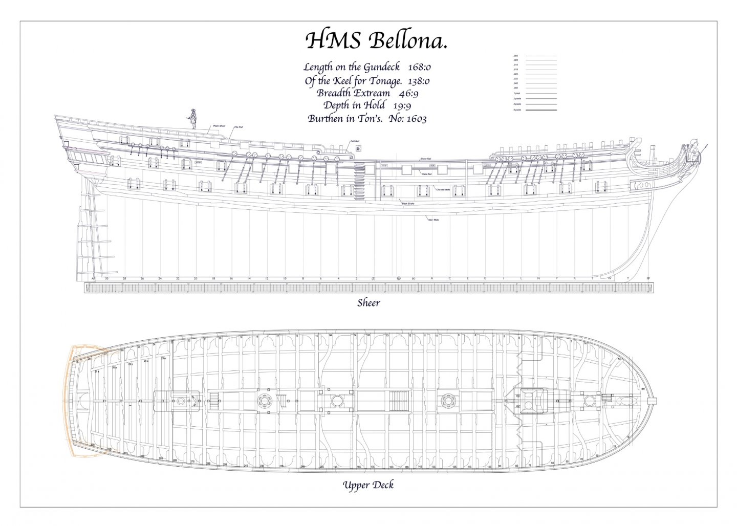
A couple more sheets. These are not yet really finished or laid out as final drawings, but they do help pull together a lot of work I have done on more detail. Just in case the electronic world fails, I will have hard copies of the basic information!
-
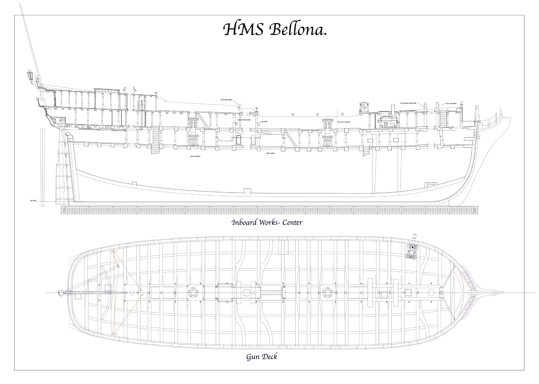
Hi druxey, I so wish I could take a jewelry class somewhere. I seen now how exceedingly helpful that would be. Silver soldering still eludes me... Other things in life have taken me away from the shop. But while distracted by other things, it helped clarify my next steps, resolving the numerous chicken and egg issues of what has to come before what. I have concluded that I cannot install the barrels of the guns on the gundeck afterwards. The stool bed and wedged quoin are way too delicate; several have broken off just picking up the carriages. I will need to epoxy the barrels both at the capsquares and at the quoin, possibly pinning somehow at the stool and quoin. So all of this has to happen before I start closing in the gundeck with the upper deck over it. And once the cannon are sticking out (druxey, is that the official naval description?), I need to avoid putting the hull on its side or perhaps even upside down. So everything requiring turning the hull upside down or sideways needs to be completed before the cannon go in and I can start on the upper decks. So, I first need to finish as much carpentry work as possible that will create shavings inboard, so I can tip the hull over and clean it out before proceeding. This means cutting all of the mortises for the beams on the upper deck, quarterdeck and forecastle, and roundhouse. Also, drilling the hawse holes. Then I need to finish up the outboard work including planking as much as possible, so I can turn the hull on its sides for painting the wales and the cutwater at the stem. I also need to consider finishing more of the stern works, which will also require turning the hull upside down--particularly for the frieze painting on the lower counter. Next step, then, cutting the beam mortises. Last time, I laboriously measured each beam location from the drawing, then measured from a station line on the hull. I had to square every beam up, to ensure they were parallel. This was complicated by the fact that many beams were asymmetrical due to the halved joint between the two parts. Each side was offset a little from the other side. Now many years later, with CAD drawings available, I am planning to print the upper deck, glue it to some stiff card, and lay it on the beam shelves. Then I can simply mark the location of each beam for the mortise. For the first time, I took electronic copies of my CAD drawings to the local UPS store, where they printed out very accurately dimensioned sheets on 30 X 42 inch paper. Doesn't look too bad, hate to cut up the sheet. But it was only $3 US per sheet, so I will go back for more. Mark
-
Michael, Lovely, lovely work. This truly is a work of art. And when did Angus start hanging around the shop? Mark
-
druxey, a workshop on jewelry making, or miniature metal smithing for ship models, would be a welcome break right now. If only.... Guy, happy to help out. I have learned so much from others on this website, I am glad I can contribute some myself. I am at a crossroads on the Bellona right now. I am trying to think ahead to the order in which things must be done so I don't tangle myself up. I was headed towards installing all of the standards, gun carriages and ironwork, but then thought that cutting the mortises for the decks above would be spraying wood shavings all over the delicate gun hardware, impossible to clean away without potentially breaking things. Also, I still have to turn the hull upside down to mask and paint the wales, which probably should be done before all of the delicate stuff is installed on the gun deck. And as long as I am painting the wales, I might as well do the paint on the stem, which first needs the cheeks and hawse holes pushed along. Long story short, I think I need to move onto more external work and painting, and then cut mortises and fit beams for upper decks. Only then should I finish up the work on the gundeck, when it is a little less vulnerable to this other work. It will be a bear to fix anything down there once the upper decks start to go in. At least this is my story today.....🙂 Mark
-
Gary, I linked all of my dust collection hoses to one dust collector by putting gates at the back of my workbench, all connected together by PVC pipe underneath the fir covering board. The PVC then hooks up the dust collector. It has an on-off switch powered by the tool turning on, so all of the tools are plugged into a power strip, which is then plugged into the dust collector. That means any tool turning on will turn on the dust collector. Sometimes I forget to open and close the right gates, but I find out soon enough when the dust starts swirling up. When I install your solution to the Mill and Lathe hose, I will make a junction box like yours and the hook it up to the gate at the back of the workbench, I am thinking.... Mark

-
L.H., yes, you guessed it! Marc, here are the cutter and the parallel jaw pliers. The pliers are: https://contenti.com/brass-jaw-flat-nose-parallel-pliers The cutters are Lindstrom 8141, found on this page: https://contenti.com/pliers-cutters-n-shears/jeweler-s-pliers/lindstrom-pliers/lindstrom-80-series-micro-bevel-flush-cutters
-
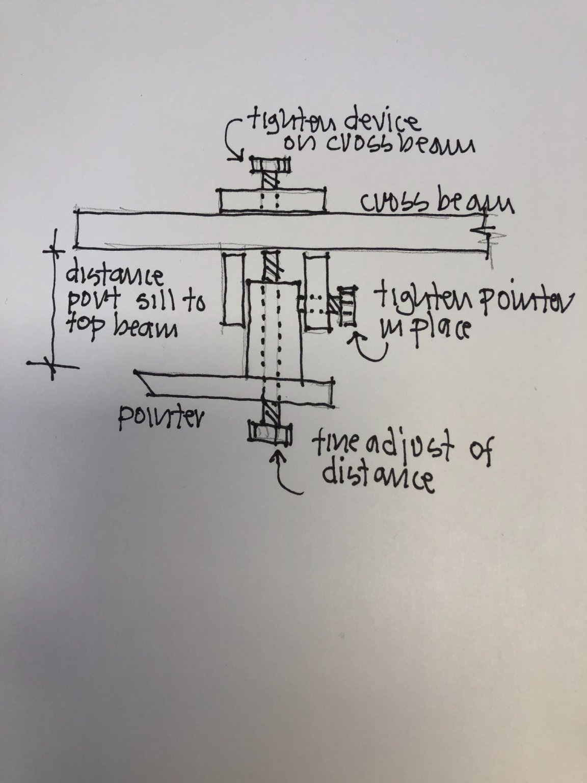
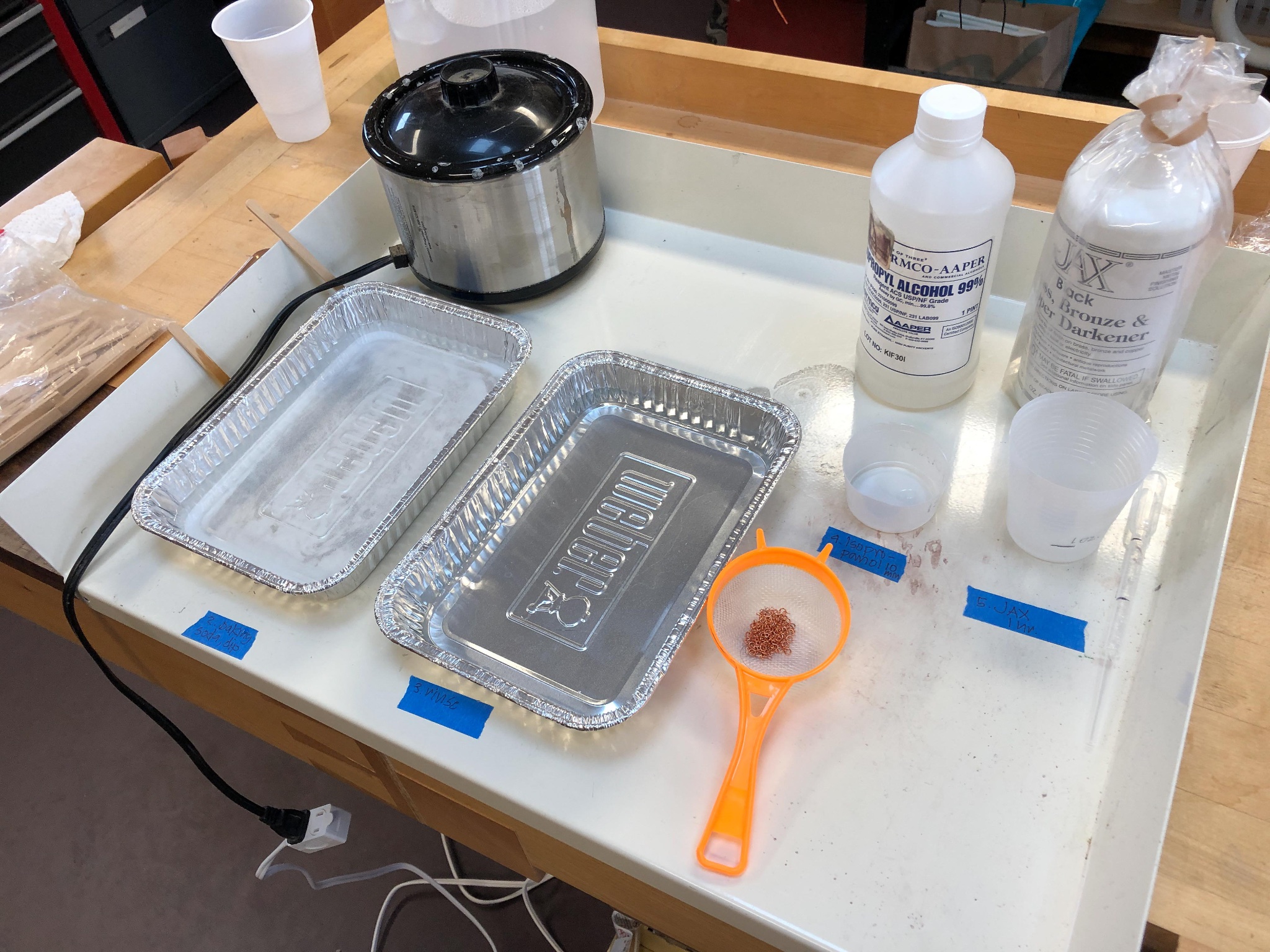
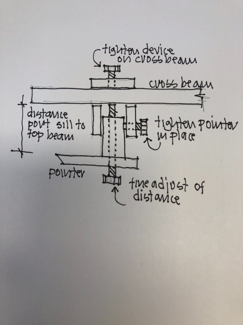
Thanks, everyone, for your comments. Marc, the parallel jaw pliers are terrific for flattening a construction without denting the soft metal. And they are not all that expensive, relative to other jeweler's pliers. I found mine at Contenti. Tony, my strainer is plastic, so I hoped that would be OK in the pickle. I did make the mistake at the very end of using the strainer in the baking soda and then putting it back into the pickle without first washing it. So I probably did kill the pickle with that mis-step. I will look into the bar-tender strainers in the future. It would be nice to keep the parts in a strainer all the way through to the JAX solution, instead of picking them out individually with tweezers. But I take your caution, and ideally would use separate strainers for each step of the process. The smallest pieces, the wedges for retaining the carriage trucks, were so small that many actually fell through the strainer mesh. Very bitty process.... Guy, here is a sketch of the measuring device. The horizontal screw locks the pointer in place, after using the fine adjustment screw at the bottom.
-
I vaguely recall an exhibit of the Sutton Hoo ship in the British museum many decades ago, like part of a cast of the dig? Do I remember this correctly, and if so, is it still in the British Museum public exhibits? Mark
-
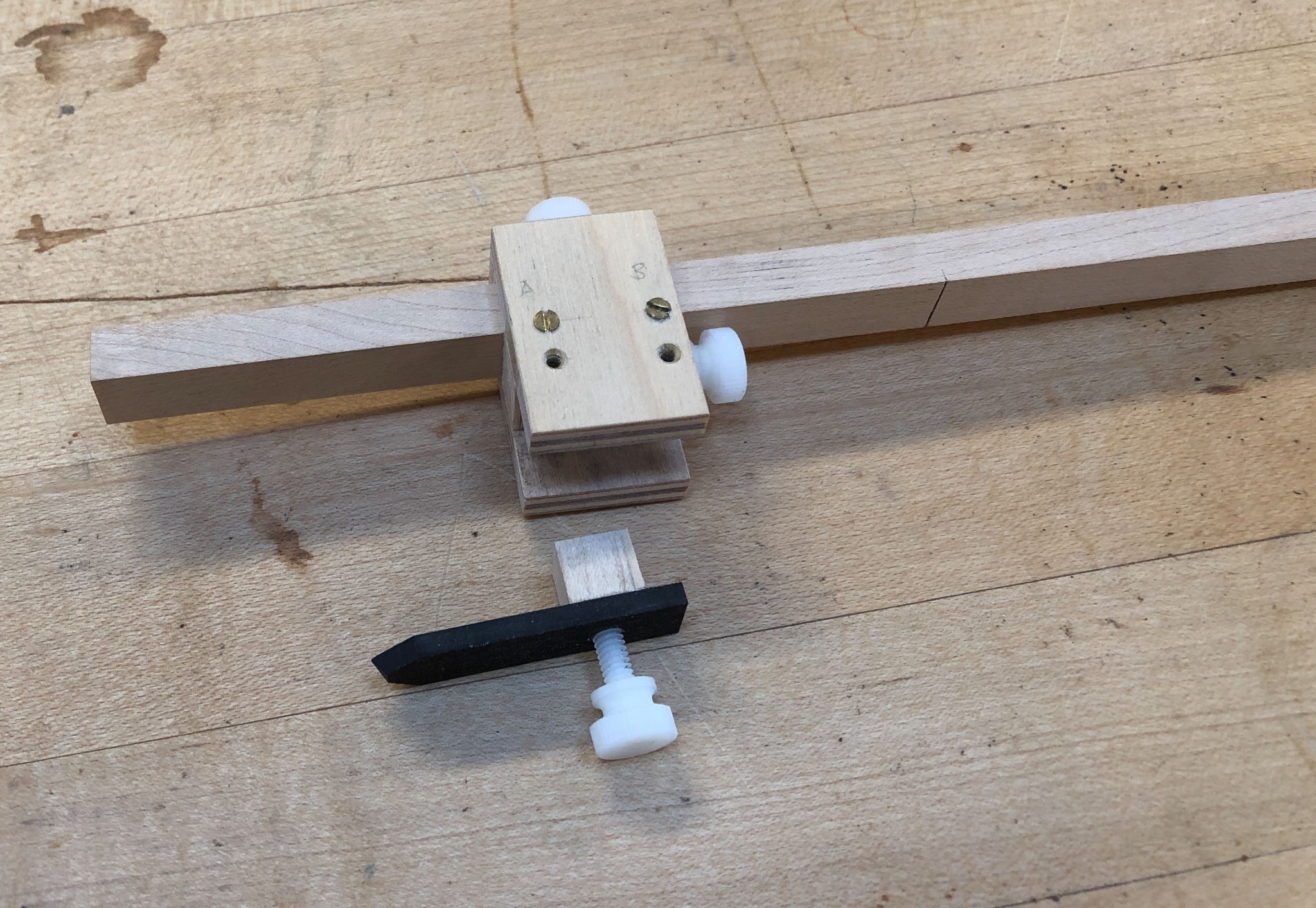
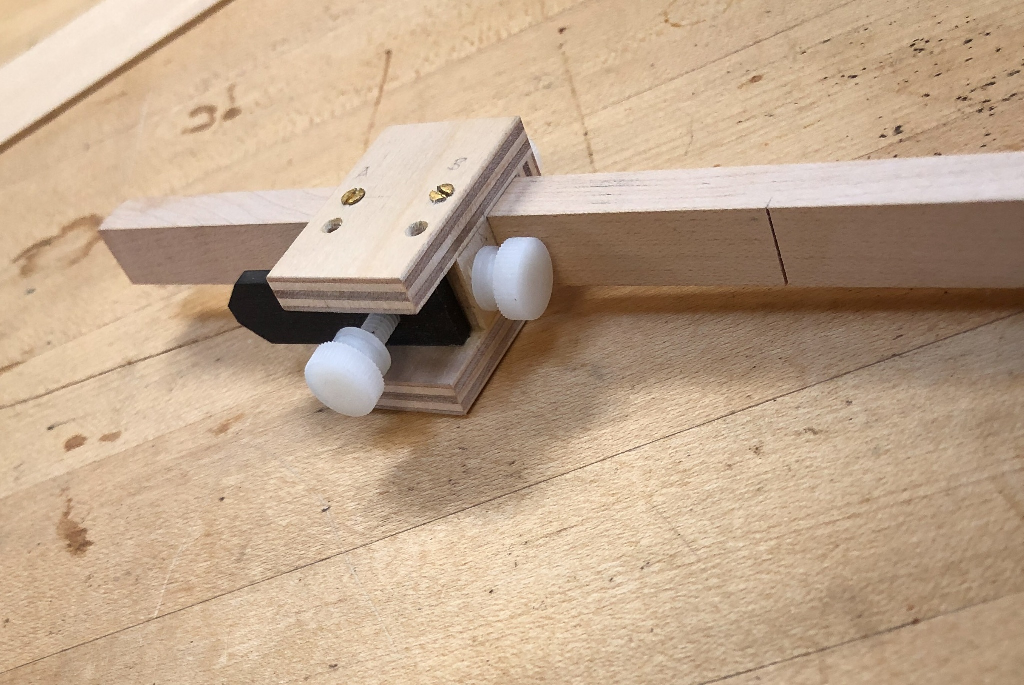
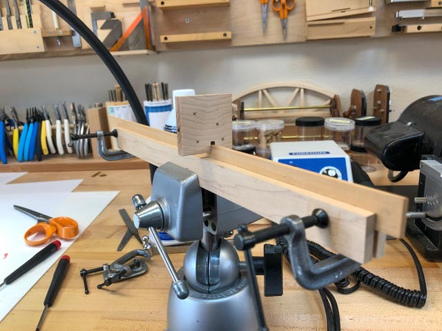
Thanks, druxey. Here is a closer look at the marking jig. The ebony pointer slides up between the two side pieces of the shell, and has a screw on the bottom for fine adjustment. And then a screw at the right tightens it down in place. The top screw tightens the entire sliding mechanism against the bar. The empty screw holes were drilled when I used this for the gun deck. They got in the way when I had to shorten the throw for the upper deck. Should have thought ahead way back then.... Mark


-
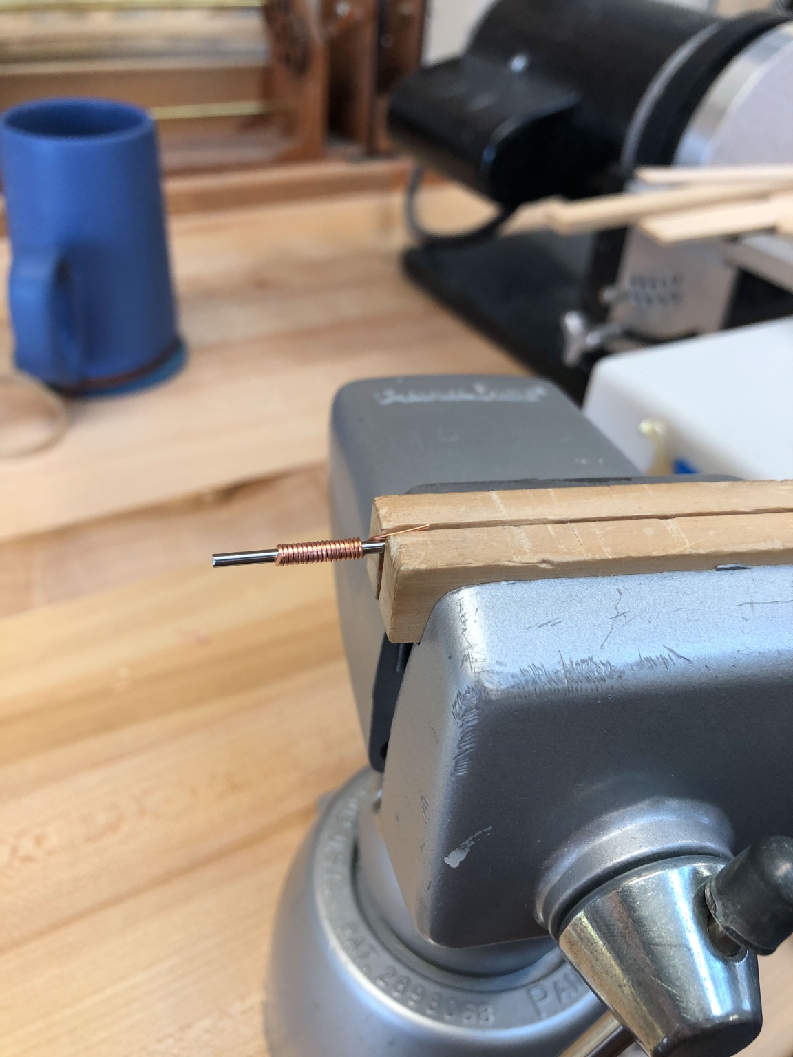
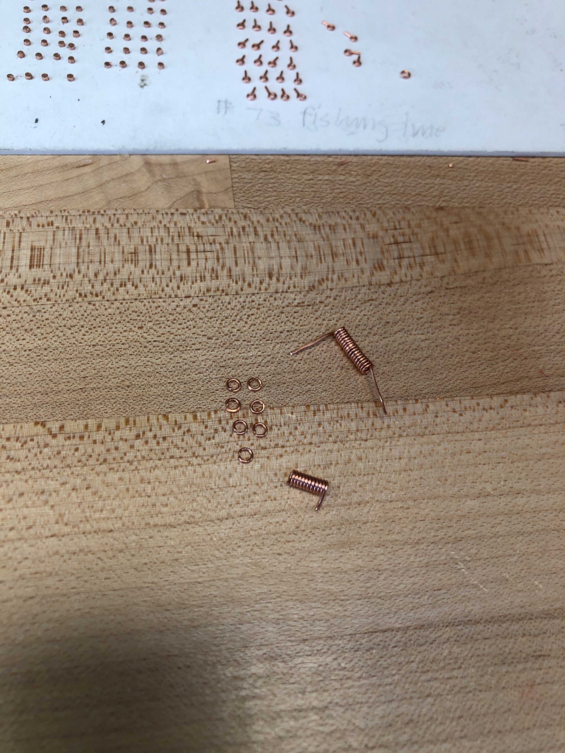
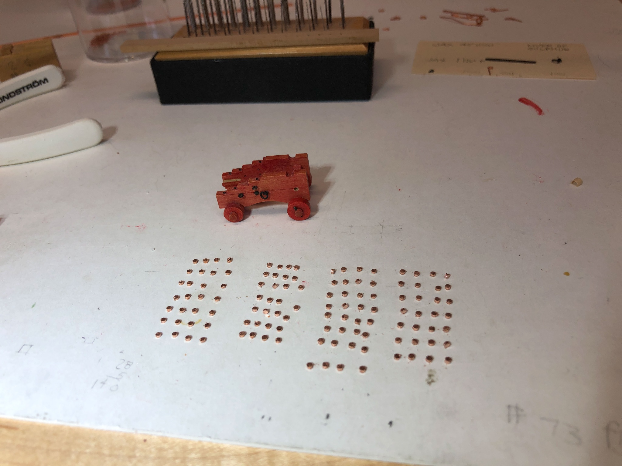
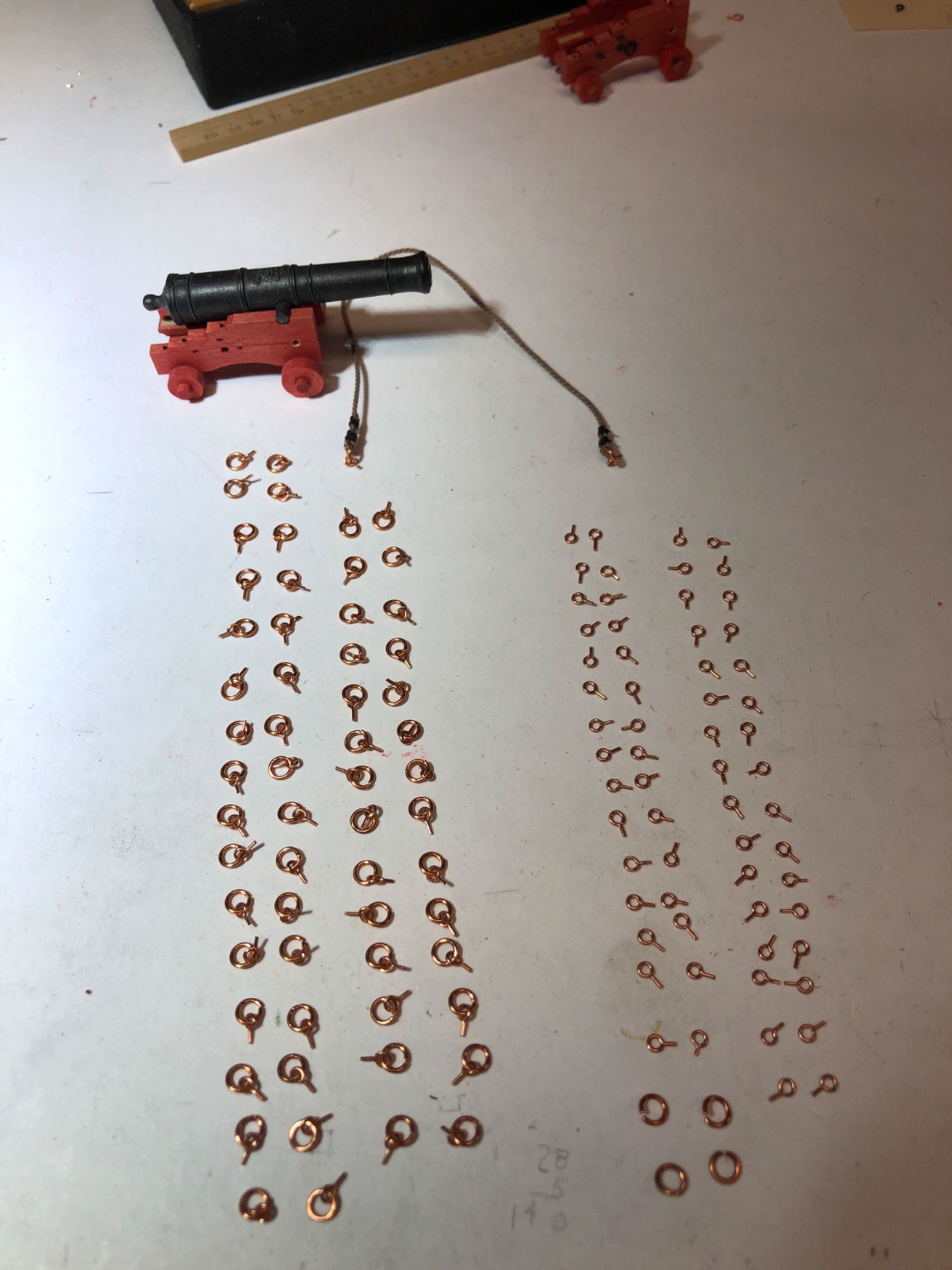
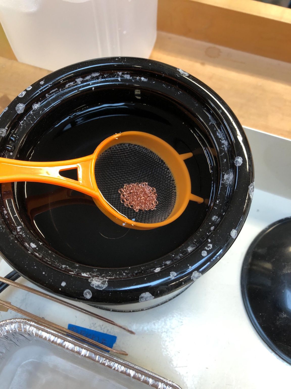
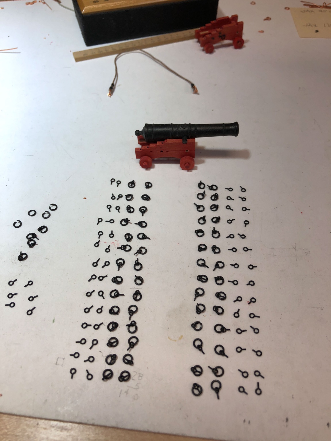
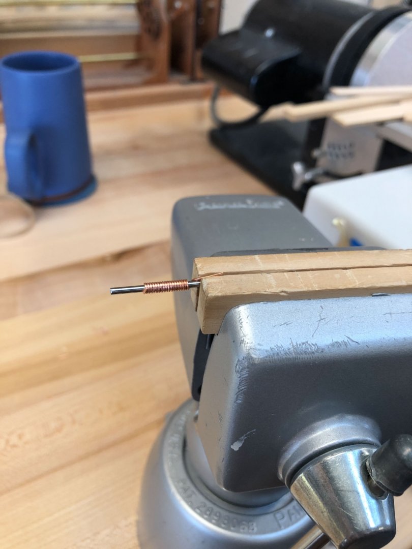
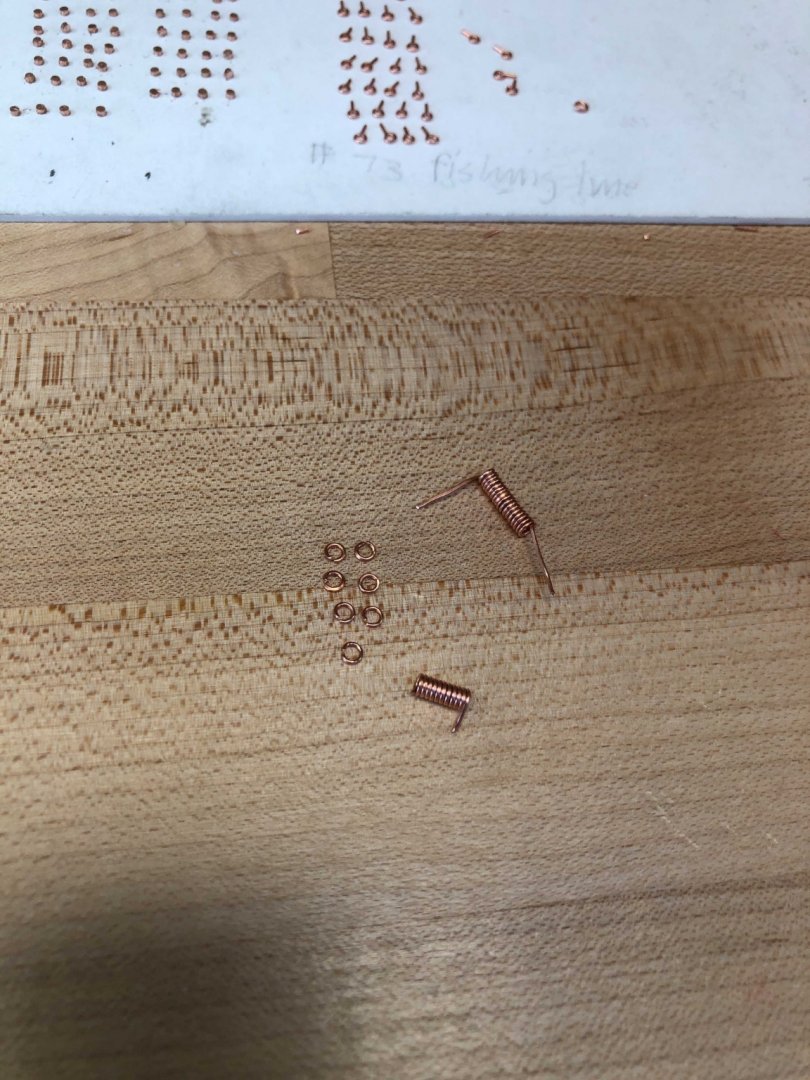
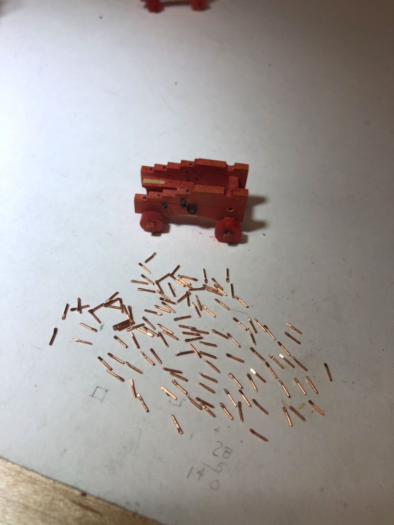
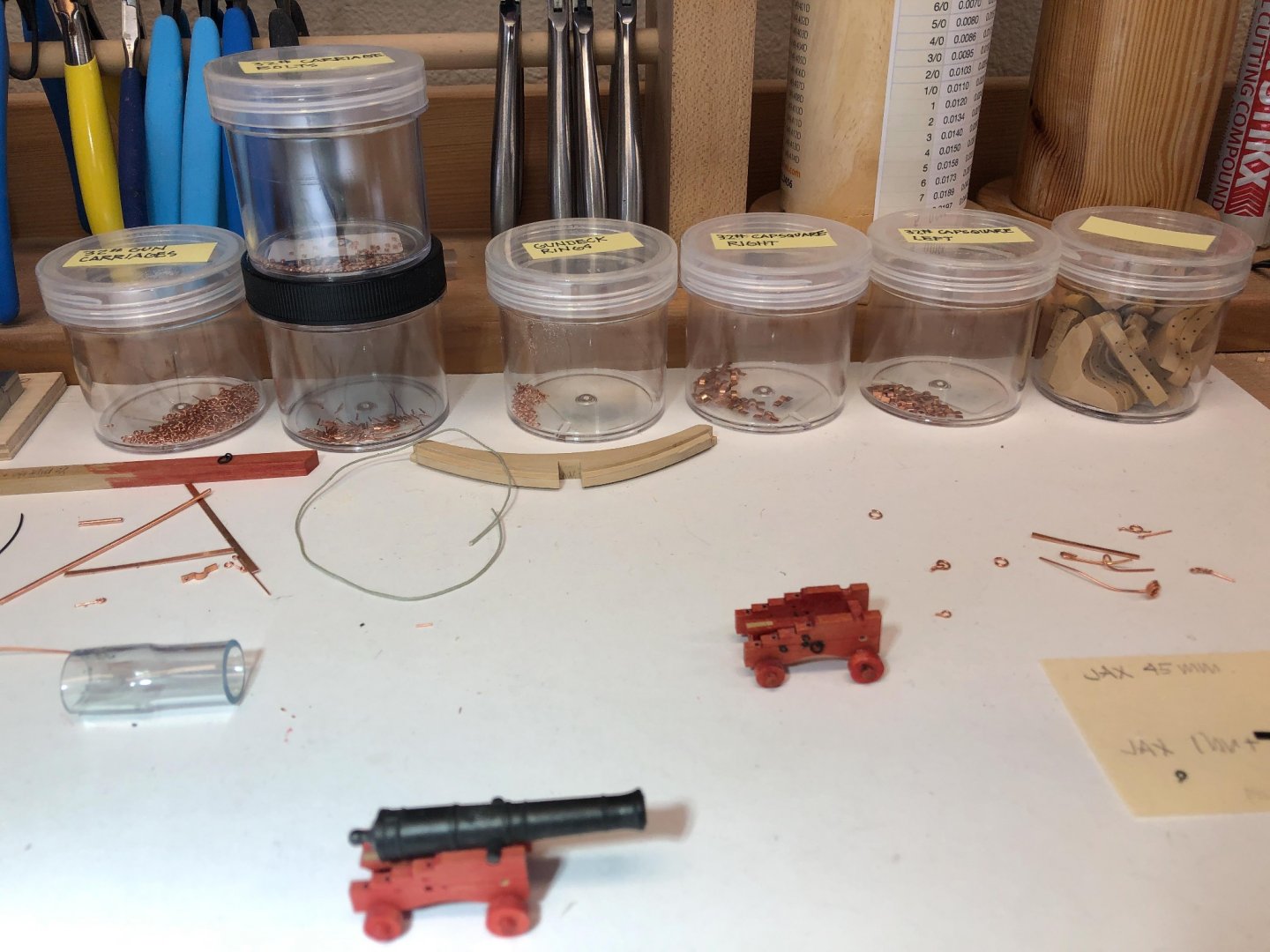
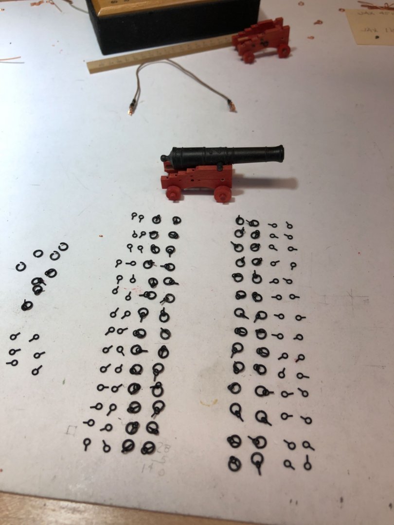
druxey, you are right, those parallel pliers are a god-send. Flattens things out without marring the soft copper. And nice capsquares. The giveaway of built up construction is that the join between the flat and the curve comes to a sharp 90 degree corner. Even the best bending still leaves a small radius at this intersection. I have been busy for the last week constructing all of the metal for the gun deck. Easy with jigs, but many, many pieces to make over and over. I learned from YouTube videos how to make the rings, which are called jump rings in the jewelry world. Clamp a drill bit of the right internal diameter for the ring into a vise. Then tightly wrap copper wire of the correct diameter around the drill bit. Remove from drill bit. Use sharp angle cutters to cut a square end at the beginning of the coil, then reverse the cutter to cut another square end facing the first. A perfect ring drops off the coil. Cut a new square end, reverse the cutters and cut the opposite end square. Repeat. I used two parallel jaw pliers opposing each other to open up the ring enough to drop in an eyebolt, then close up the ring. A trick I learned online was to twist the pliers back and forth a few times, listening for a clicking sound as the two ends of the ring pass by each other. This helps form a ring without a gap. And then there were all of the other metal pieces for the gun carriages, the ends of the bolts, and the wedges for retaining the trucks to the axles. And slowly but surely the metal parts accumulated: I blackened in batches, to keep different types separate (left and right cap squares, rings for carriages vs. rings for deck vs. rings for quickwork). Following Greg's good advise (above), I cleaned in pickle, then neutralized in baking soda and water, then I used 99% isopropyl alcohol). A final soak in diluted Jax blackening for copper. The pieces were so tiny I used the orange filter to put into the pickle and baking soda. But then I had to dump them individually into the alcohol and JAX. It was pretty tedious picking them all up individually with tweezers at this point. The resulting blackened pieces are really quite wonderful in color and luster: While waiting for some of these processes, I started marking out the upper deck height, in anticipation of finally moving on to the next deck in a few weeks. I dug out an old jig I used to mark the height of the gun deck. It has a bar between opposite gun ports, and a device that slides up to the side at the correct distance down from the port. I then run a pencil over the ebony pointer, to get the mark on the side at the correct height. Without this jig, it would be very difficult to measure down accurately with so much tumblehome. This ensures that the final beam height will be exactly parallel to the gun ports. The jig allows the black pointer to slide up and down and lock at the correct height within the larger shell of the device. Best wishes, Mark


-
Gary, nice! Is that little funnel at the end nearest the lathe also part of the Loc Line system? Mark